JP5037525B2 - Method for connecting a monitoring system and a monitoring device to a service server - Google Patents
Method for connecting a monitoring system and a monitoring device to a service server Download PDFInfo
- Publication number
- JP5037525B2 JP5037525B2 JP2008547174A JP2008547174A JP5037525B2 JP 5037525 B2 JP5037525 B2 JP 5037525B2 JP 2008547174 A JP2008547174 A JP 2008547174A JP 2008547174 A JP2008547174 A JP 2008547174A JP 5037525 B2 JP5037525 B2 JP 5037525B2
- Authority
- JP
- Japan
- Prior art keywords
- server
- monitoring device
- service
- control server
- monitor
- Prior art date
- Legal status (The legal status is an assumption and is not a legal conclusion. Google has not performed a legal analysis and makes no representation as to the accuracy of the status listed.)
- Active
Links
Images


Classifications
-
- H—ELECTRICITY
- H04—ELECTRIC COMMUNICATION TECHNIQUE
- H04L—TRANSMISSION OF DIGITAL INFORMATION, e.g. TELEGRAPHIC COMMUNICATION
- H04L41/00—Arrangements for maintenance, administration or management of data switching networks, e.g. of packet switching networks
- H04L41/08—Configuration management of networks or network elements
- H04L41/0803—Configuration setting
- H04L41/0806—Configuration setting for initial configuration or provisioning, e.g. plug-and-play
- H04L41/0809—Plug-and-play configuration
-
- H—ELECTRICITY
- H04—ELECTRIC COMMUNICATION TECHNIQUE
- H04L—TRANSMISSION OF DIGITAL INFORMATION, e.g. TELEGRAPHIC COMMUNICATION
- H04L41/00—Arrangements for maintenance, administration or management of data switching networks, e.g. of packet switching networks
- H04L41/34—Signalling channels for network management communication
-
- H—ELECTRICITY
- H04—ELECTRIC COMMUNICATION TECHNIQUE
- H04L—TRANSMISSION OF DIGITAL INFORMATION, e.g. TELEGRAPHIC COMMUNICATION
- H04L61/00—Network arrangements, protocols or services for addressing or naming
-
- H—ELECTRICITY
- H04—ELECTRIC COMMUNICATION TECHNIQUE
- H04L—TRANSMISSION OF DIGITAL INFORMATION, e.g. TELEGRAPHIC COMMUNICATION
- H04L61/00—Network arrangements, protocols or services for addressing or naming
- H04L61/50—Address allocation
- H04L61/5007—Internet protocol [IP] addresses
- H04L61/5014—Internet protocol [IP] addresses using dynamic host configuration protocol [DHCP] or bootstrap protocol [BOOTP]
-
- H—ELECTRICITY
- H04—ELECTRIC COMMUNICATION TECHNIQUE
- H04L—TRANSMISSION OF DIGITAL INFORMATION, e.g. TELEGRAPHIC COMMUNICATION
- H04L65/00—Network arrangements, protocols or services for supporting real-time applications in data packet communication
- H04L65/40—Support for services or applications
-
- H—ELECTRICITY
- H04—ELECTRIC COMMUNICATION TECHNIQUE
- H04L—TRANSMISSION OF DIGITAL INFORMATION, e.g. TELEGRAPHIC COMMUNICATION
- H04L67/00—Network arrangements or protocols for supporting network services or applications
- H04L67/01—Protocols
- H04L67/02—Protocols based on web technology, e.g. hypertext transfer protocol [HTTP]
- H04L67/025—Protocols based on web technology, e.g. hypertext transfer protocol [HTTP] for remote control or remote monitoring of applications
-
- H—ELECTRICITY
- H04—ELECTRIC COMMUNICATION TECHNIQUE
- H04L—TRANSMISSION OF DIGITAL INFORMATION, e.g. TELEGRAPHIC COMMUNICATION
- H04L67/00—Network arrangements or protocols for supporting network services or applications
- H04L67/01—Protocols
- H04L67/12—Protocols specially adapted for proprietary or special-purpose networking environments, e.g. medical networks, sensor networks, networks in vehicles or remote metering networks
- H04L67/125—Protocols specially adapted for proprietary or special-purpose networking environments, e.g. medical networks, sensor networks, networks in vehicles or remote metering networks involving control of end-device applications over a network
-
- H—ELECTRICITY
- H04—ELECTRIC COMMUNICATION TECHNIQUE
- H04L—TRANSMISSION OF DIGITAL INFORMATION, e.g. TELEGRAPHIC COMMUNICATION
- H04L67/00—Network arrangements or protocols for supporting network services or applications
- H04L67/50—Network services
- H04L67/51—Discovery or management thereof, e.g. service location protocol [SLP] or web services
-
- H—ELECTRICITY
- H04—ELECTRIC COMMUNICATION TECHNIQUE
- H04L—TRANSMISSION OF DIGITAL INFORMATION, e.g. TELEGRAPHIC COMMUNICATION
- H04L41/00—Arrangements for maintenance, administration or management of data switching networks, e.g. of packet switching networks
- H04L41/08—Configuration management of networks or network elements
- H04L41/085—Retrieval of network configuration; Tracking network configuration history
- H04L41/0853—Retrieval of network configuration; Tracking network configuration history by actively collecting configuration information or by backing up configuration information
- H04L41/0856—Retrieval of network configuration; Tracking network configuration history by actively collecting configuration information or by backing up configuration information by backing up or archiving configuration information
-
- H—ELECTRICITY
- H04—ELECTRIC COMMUNICATION TECHNIQUE
- H04L—TRANSMISSION OF DIGITAL INFORMATION, e.g. TELEGRAPHIC COMMUNICATION
- H04L63/00—Network architectures or network communication protocols for network security
- H04L63/08—Network architectures or network communication protocols for network security for authentication of entities
Landscapes
- Engineering & Computer Science (AREA)
- Computer Networks & Wireless Communication (AREA)
- Signal Processing (AREA)
- Computing Systems (AREA)
- General Health & Medical Sciences (AREA)
- Medical Informatics (AREA)
- Health & Medical Sciences (AREA)
- Multimedia (AREA)
- Computer Hardware Design (AREA)
- Computer Security & Cryptography (AREA)
- General Engineering & Computer Science (AREA)
- Computer And Data Communications (AREA)
- Data Exchanges In Wide-Area Networks (AREA)
- Hardware Redundancy (AREA)
- Small-Scale Networks (AREA)
Abstract
Description
(発明の技術分野)
本発明は、モニタシステムおよびかかるシステムのデバイスに関し、特に本発明は、モニタデバイスをサービスサーバーに接続するための方法およびかかる接続を可能にするモニタシステムに関する。
(Technical field of the invention)
The present invention relates to a monitoring system and devices of such a system, in particular, the present invention relates to a method for connecting a monitoring device to a service server and a monitoring system enabling such a connection.
(発明の背景)
コンピュータネットワークを介し、モニタサーバーまたは監視サーバーに接続された、注目する建物、エリアおよび/またはプロセスをモニタするためのモニタシステムは、次第に普及している。特にかかるモニタシステムは、デジタルモニタカメラを含む。かかるシステムが普及する1つの理由は、コンピュータネットワークが既に設置されている場合に、広い範囲のシステムが既存のネットワークを利用できることにある。
(Background of the Invention)
Monitor systems for monitoring buildings, areas and / or processes of interest connected to a monitor server or monitor server via a computer network are becoming increasingly popular. In particular, such a monitoring system includes a digital monitor camera. One reason for the widespread use of such systems is that a wide range of systems can use existing networks when computer networks are already installed.
一般的なコンピュータネットワークを監視ネットワークとして使用する別の理由は、モニタシステムのために構築しなければならないネットワークを使って、他のタイプの機器、例えばコンピュータ、サーバーおよび周辺機器を接続できることにある。これら理由から、この技術は単一の、または数個のモニタデバイスを必要とする組織/個人だけでなく、多数のモニタデバイスを必要とする組織/個人も満たすことができる。 Another reason for using a typical computer network as a monitoring network is that other types of equipment, such as computers, servers and peripherals, can be connected using the network that must be built for the monitoring system. For these reasons, this technique can meet not only organizations / individuals that require a single or several monitoring devices, but also organizations / individuals that require multiple monitoring devices.
かかるモニタシステムでは、モニタデバイスはモニタデータをサービスサーバーに送るようになっており、サービスサーバーはモニタデータまたは情報を処理し、ユーザーがモニタデータにアクセスするためのデータを作成し、モニタ情報をロギングしたり、モニタデータを記憶したり、またはモニタシステムの当業者に知られている他の目的を果たすことができる。 In such a monitor system, the monitor device sends monitor data to a service server, the service server processes the monitor data or information, creates data for the user to access the monitor data, and logs the monitor information. Or store monitor data, or serve other purposes known to those skilled in the art of monitor systems.
一般的には、かかるシステムのモニタデバイスはある会社によって製造され、サービスサーバーは別の会社であるモニタサービスプロバイダによって維持される。このモニタサービスプロバイダは、かかるサービスを提供することを専門にする会社または組織とし得る。しかしながら、モニタサービスプロバイダは、モニタされる建物、エリアおよび/またはプロセスに関連する会社、例えばその建物を所有したり、またはモニタされるサイトで営業する会社でもある。今日のシステムでは、ユーザーがモニタデバイスに直接アドレスをキー入力することにより、サービスサーバーに対するアドレスを各モニタデバイスに提供できる。モニタデバイスとサービスサーバーの間との接続を達成する別の方法は、コンピュータネットワークに接続されたコンピュータを介し、サービスサーバーに接続し、サービスサーバーにモニタデバイスを登録することである。 In general, the monitoring device of such a system is manufactured by one company and the service server is maintained by a monitoring service provider which is another company. The monitor service provider may be a company or organization that specializes in providing such services. However, the monitor service provider is also a company associated with the monitored building, area and / or process, for example, a company that owns the building or operates at the monitored site. In today's systems, each monitor device can be provided with an address for the service server by the user keying the address directly into the monitor device. Another way to achieve the connection between the monitoring device and the service server is to connect to the service server and register the monitoring device with the service server via a computer connected to the computer network.
今日、サービスサーバーのアドレスのかかるプログラミング、すなわちサービスサーバーへのモニタデバイスの登録は、モニタデバイスのインストールプロセス中にユーザーまたは個人がモニタデバイスをインストールすることによって実行されている。 Today, such programming of the address of the service server, i.e. registration of the monitor device with the service server, is performed by the user or individual installing the monitor device during the monitor device installation process.
上記モニタシステムに関連する一般的な問題は、インストールを実行する個人がモニタデバイスにプログラムを組み込んだ経験がないことがあり、プログラムに時間がかかり、インストールする個人がモニタデバイスにエラーデータを入力し得ることである。 Common problems associated with the above monitoring systems are that the individual performing the installation may not have experience installing the program on the monitor device, the program takes time, and the installing individual enters error data into the monitor device. Is to get.
本発明の目的は、改良されたモニタシステムを提供することにある。 It is an object of the present invention to provide an improved monitoring system.
この目的は、請求項1記載のモニタデバイスをサービスサーバーに接続する方法、および請求項11記載のモニタシステム、請求項18記載の制御サーバー、および請求項21記載のモニタデバイスによって達成される。本発明の実施例は従属項に開示されている。
This object is achieved by a method for connecting a monitoring device according to
特に本発明の1つの様相によれば、特に本発明の第1の様相によれば、モニタデバイスをサービスサーバーに接続するための方法は、制御サーバーに関するアドレスを前記モニタデバイスのメモリから検索するステップと、前記モニタデバイスで生じた接続事象に応答し、制御サーバーに関連するアドレスに前記モニタデバイスからの接続メッセージを送るステップと、前記制御サーバーにおいて、前記モニタデバイスと前記制御サーバーとの間の通信から識別子を抽出するステップと、前記制御サーバーにおいて、前記抽出した識別子に関連するサービスサーバーを識別するステップと、前記制御サーバーから前記モニタデバイスに前記識別されたサービスサーバーに関連するアドレスを送るステップと、前記識別されたサービスサーバーに関連するアドレスの受信に応答し、前記モニタデバイスから前記識別されたサービスサーバーへ、接続メッセージを送るステップと、前記モニタデバイスと前記識別されたサービスサーバーとの間にサービス接続を設定するステップとを備える。 In particular, according to one aspect of the present invention, and in particular according to the first aspect of the present invention, a method for connecting a monitoring device to a service server comprises the steps of retrieving an address for the control server from the memory of the monitoring device. Sending a connection message from the monitor device to an address associated with the control server in response to a connection event occurring at the monitor device; and in the control server, communication between the monitor device and the control server Extracting an identifier from the control server; identifying, in the control server, a service server associated with the extracted identifier; and sending an address associated with the identified service server from the control server to the monitoring device; The identified service server Responsive to receiving an associated address, sending a connection message from the monitoring device to the identified service server; and setting up a service connection between the monitoring device and the identified service server. Prepare.
本発明の第2の様相によれば、モニタシステムは、モニタデバイスと、制御サーバーと、複数のサービスサーバーと、前記サーバーと前記モニタデバイスとを接続するネットワークとを備える。 According to the second aspect of the present invention, the monitor system includes a monitor device, a control server, a plurality of service servers, and a network connecting the server and the monitor device.
前記モニタデバイスは、接続アドレスを含むメモリと、イニシエイション事象(initiation event:起動事象、スタート事象)に応答し、前記ネットワークを通して前記接続アドレスに接続メッセージを送るようになっているイニシエイション手段と、前記ネットワークを介し受信したメッセージ内のアドレスに、新しい接続メッセージを送るようになっている手段とを備える。 The monitor device includes a memory including a connection address, an initiation means adapted to send a connection message to the connection address through the network in response to an initiation event (start event), the network Means for sending a new connection message to the address in the message received via.
前記制御サーバーは、前記モニタデバイスと前記制御サーバーとの間の通信から識別子を抽出するようになっている識別抽出器と、前記抽出した識別子と制御サーバーまたはサービスサーバーとを照合し、一致したサービスサーバーに対するアドレスを検索するようになっている照合手段と、前記検索されたアドレスを含むメッセージを発生し、前記発生されたメッセージを前記モニタデバイスに送るようになっているメッセージ発生器とを備える。 The control server collates an identification extractor adapted to extract an identifier from communication between the monitor device and the control server, and the extracted identifier and the control server or service server, thereby matching services. Collating means adapted to retrieve an address for a server; and a message generator adapted to generate a message including the retrieved address and to send the generated message to the monitoring device.
各サービスサーバーは、モニタデバイスからのモニタデータを受信し、処理するための手段とを備える。 Each service server comprises means for receiving and processing monitor data from the monitor device.
上記方法およびシステムの利点として、デバイスのメンテナンスおよび設置を容易にできることが挙げられる。その理由は、モニタデバイスは人が好ましいサービスサーバーに対するアドレスをキー入力しなくても、制御サーバーにより好ましいサービスサーバーにガイドされるからである。更にこのようにシステムをより効率的に維持できる。その理由は、制御サーバーはユーザーまたは人がモニタデバイスを維持するよりも新しいか、または変化するサービスサーバーのアドレスによって更新を維持することがより容易または効率的にできるからである。 An advantage of the above methods and systems is that device maintenance and installation can be facilitated. The reason is that the monitoring device is guided by the control server to the preferred service server without the person having to key in the address for the preferred service server. Furthermore, the system can be maintained more efficiently in this way. The reason is that the control server can more easily or efficiently maintain updates with a new or changing service server address than the user or person maintains the monitoring device.
別の利点は、モニタデバイスが制御サーバー(1つまたは複数)と、サービスサーバー(1つまたは複数)とのすべての接続をイニシエイト(initiate:スタート、起動)させ、これによってアクセス制限デバイス、例えばファイアーウォール、NAT(ネットワークアドレス変換)、ISP(インターネットサービスプロバイダ)の後方からのモニタデバイスの統合を促進し、かかるアクセス制限デバイス外に達するシステムにダイナミックアドレスを提供できることである。 Another advantage is that the monitoring device initiates all connections between the control server (s) and the service server (s), thereby restricting access to a device such as a firewall. It facilitates the integration of monitoring devices from behind a wall, NAT (Network Address Translation), ISP (Internet Service Provider), and can provide dynamic addresses to systems that reach outside such access restricted devices.
本発明の別の実施例によれば、上記方法においてモニタデバイスのメモリから制御サーバーに関するアドレスを初期検索(initial retrieval)すると、制御サーバーに関するあらかじめコンフィギュアされたアドレスが戻され、モニタデバイスからあらかじめコンフィギュアされたアドレスへの接続メッセージの初期の送信は、モニタデバイスのイニシエイション事象に応答して実行される。 According to another embodiment of the present invention, upon initial retrieval of the address for the control server from the memory of the monitoring device in the above method, the preconfigured address for the control server is returned and preconfigured from the monitoring device. The initial transmission of the connect message to the addressed figure is performed in response to the initiation event of the monitor device.
このように初期制御サーバー(initial control server)を構成する利点は、システムのモニタデバイスの設置およびカスタム化が容易となることである。モニタデバイスのイニシエイション時に、モニタデバイスのイニシエイションの結果、自動的に所定の制御サーバーにコンタクトするので、設置中にモニタデバイスへアドレスを提供する必要はなくなるので、設置は容易である。モニタデバイスと制御サーバー、例えば初期制御サーバーとの間の初期通信(initial communication)時に、モニタデバイスに関する特定の属性(properties:プロパティ)を提供できるので、カスタム化が促進される。従って、モニタデバイスのメーカーはモニタデバイスの異なるロット(different batches)に対し、異なる製造プロセスを有する必要はない。 The advantage of configuring the initial control server in this way is that it is easy to install and customize the monitor device of the system. When the monitor device is initialized, the monitor device automatically contacts a predetermined control server as a result of the monitor device initialization. Therefore, it is not necessary to provide an address to the monitor device during the installation, so that the installation is easy. Customization is facilitated because certain properties regarding the monitoring device can be provided during initial communication between the monitoring device and the control server, eg, the initial control server. Thus, monitor device manufacturers need not have different manufacturing processes for different batches of monitor devices.
換言すれば、本発明のこの実施例に係わるシステムは、デバイスのカスタム化に関するメーカーの問題を解消できる。例えば製造中、今日のモニタシステムのモニタデバイスを、異なるサービスプロバイダと関連付ける必要があり、関連するサービスプロバイダに対してカスタム化されたプロセス内で、サービスプロバイダに関連する各デバイスにプログラムを組まなければならない。従って、メーカーは異なるサービスプロバイダ用のデバイスに対し、複数の異なる製造プロセスを設けなければならない。更に、特定のサービスプロバイダに対してプログラムされたデバイスを特定のサービスプロバイダまたは特定のサービスプロバイダの顧客に出荷し、販売しなければならない。 In other words, the system according to this embodiment of the present invention can eliminate the manufacturer's problem with device customization. For example, during manufacturing, monitor devices in today's monitoring systems need to be associated with different service providers, and each device associated with a service provider must be programmed within a process customized to the associated service provider. Don't be. Therefore, manufacturers must provide multiple different manufacturing processes for devices for different service providers. In addition, devices programmed for a particular service provider must be shipped and sold to a particular service provider or a customer of a particular service provider.
この実施例の別の利点は、モニタデバイスを中央で管理できるようになることである。 Another advantage of this embodiment is that the monitoring device can be managed centrally.
更に別の実施例によれば、接続メッセージのモニタデバイスから制御サーバーへの送信は、サービスサーバーのアドレスをモニタデバイスに提供する制御サーバーに接続メッセージをモニタデバイスから送る前に、少なくとも1回行われる。 According to yet another embodiment, the connection message is sent from the monitoring device to the control server at least once before the connection message is sent from the monitoring device to the control server that provides the address of the service server to the monitoring device. .
複数の制御サーバーを配置し、モニタデバイスを別の制御サーバーに向ける利点は、正しいサービスサーバーにモニタデバイスを向ける責任を、システムの一般的機能に責任のあるエンティティ、例えばモニタデバイスのメーカーから、必要なサービスを提供する責任があるエンティティ、例えばサービスプロバイダに変更できることである。 The advantage of deploying multiple control servers and directing the monitor device to another control server is that the responsibility for directing the monitor device to the correct service server is required from the entity responsible for the general functioning of the system, eg the manufacturer of the monitor device It is possible to change to an entity responsible for providing a secure service, for example a service provider.
別の実施例によれば、サービスサーバーを識別する動作は、モニタデバイスと制御サーバーとの間の通信から、モニタデバイスに関するネットワークアドレスを抽出し、ネットワークアドレスとサービスプロバイダとを照合し、一致したサービスプロバイダに関連するサービスサーバーを選択する動作を更に含む。 According to another embodiment, the act of identifying a service server includes extracting a network address for the monitor device from communication between the monitor device and the control server, matching the network address with the service provider, and matching services. The method further includes selecting a service server associated with the provider.
少なくともネットワーク接続を行うサービスプロバイダがモニタサービスのプロバイダに関連している場合、またはそれらサービスプロバイダが同じ場合、このようにモニタデバイスに関係するネットワークアドレスを使用することにより、サービスプロバイダを識別することが容易となる。 If at least the service provider making the network connection is associated with the provider of the monitor service, or if they are the same, the network address associated with the monitor device can be identified in this way. It becomes easy.
更に別の実施例によれば、サービスサーバーを識別する動作は、モニタデバイスと制御サーバーとの間の通信において、モニタデバイスが含む識別コードを抽出し、この識別コードとサービスプロバイダとを照合し、一致したサービスプロバイダに関連するサービスサーバーを選択する動作を含む。 According to yet another embodiment, the act of identifying the service server is to extract an identification code included in the monitoring device in communication between the monitoring device and the control server, and match the identification code with the service provider; The operation includes selecting a service server associated with the matched service provider.
このように識別コードを使用することにより、種々の基準に基づき、モニタデバイスをカスタム化し、特定のモニタサービスプロバイダに接続できる。例えばモニタデバイスがモニタサービスプロバイダのサービスサーバーに接続されるという条件で、モニタデバイスを買う際に、モニタデバイスの1つのロット(batch)を、ディスカウントを提供する特定のモニタサービスプロバイダ専用とすることができる。このようにサービスプロバイダはサービスプロバイダに属す識別コードとして制御サーバーに登録された識別コードを入手し、よってサービスプロバイダはモニタデバイスのサービスプロバイダのサービスへの接続を保証できる。更に、モニタデバイスのロットを自らの建物のモニタのために、自己のサービスサーバーを有する会社専用とすることができる。 By using the identification code in this way, the monitor device can be customized and connected to a specific monitor service provider based on various criteria. For example, when buying a monitor device, provided that the monitor device is connected to the service server of the monitor service provider, one batch of the monitor device may be dedicated to a particular monitor service provider providing the discount. it can. In this way, the service provider obtains the identification code registered in the control server as the identification code belonging to the service provider, so that the service provider can guarantee the connection of the monitor device to the service provider service. Furthermore, a lot of monitor devices can be dedicated to a company having its own service server for monitoring its own building.
すべての実施例において、接続メッセージを制御サーバーまたはサービスサーバーに送るのは、モニタデバイスである。この利点は、モニタデバイスからのメッセージに応答し、例えばhttpリクエストに応答し、サーバーは制御メッセージを送るように構成できることである。従って、制御サーバーはモニタデバイスとサーバーとの間に配置された、可能性のあるアクセス制限デバイス、例えばファイアーウォール、NATサーバーなどにもかかわらず、モニタデバイスに対する制御を行うことができる。スウェーデン、S223 69 ルンド、エムダラベーゲン14、アキシスAB社によって出願された国際特許出願第WO2006/073348号に、かかる通信方式が開示されている。 In all embodiments, it is the monitoring device that sends the connection message to the control server or service server. The advantage is that the server can be configured to send a control message in response to a message from the monitoring device, eg in response to an http request. Thus, the control server can control the monitor device despite possible access restriction devices, such as firewalls, NAT servers, etc., placed between the monitor device and the server. Such a communication method is disclosed in International Patent Application No. WO2006 / 073348 filed by Sweden, S223 69 Lund, Emdarbergen 14, and Axis AB.
一実施例によれば、このシステムは制御サーバーのヒエラルキー(階層)内で高レベルまたはトップレベルの制御サーバーである、少なくとも1つの初期制御サーバーを含む複数の制御サーバーを備える。かかる初期制御サーバーは、システム内の任意の制御サーバーおよびサービスサーバーへの少なくとも間接的な接続を可能にするアドレス情報にアクセスするようになっている。 According to one embodiment, the system comprises a plurality of control servers including at least one initial control server that is a high-level or top-level control server in the control server hierarchy. Such an initial control server is adapted to access address information that enables at least an indirect connection to any control server and service server in the system.
このようにシステムを構成することにより、サーバー間に責任を分散させることが可能となる。例えばモニタデバイスに制御サーバーまたはサービスサーバーの正しいサブシステムに命令させる全責任を初期制御サーバーに与え、一方、かかるサブシステムにおける制御サーバーに、モニタデバイスが最も適したサービスサーバーに命令する責任を与えることができる。 By configuring the system in this way, responsibilities can be distributed among the servers. For example, give the initial control server full responsibility to instruct the monitoring device to the correct subsystem of the control server or service server, while giving the control server in such subsystem the responsibility of the monitoring device to order the most suitable service server Can do.
次に示す詳細な説明から、本発明の実施可能性の別の範囲が明らかとなろう。しかしながら、本発明の好ましい実施例を示す詳細な説明および特定の例は、単に説明するために示したものに過ぎないと理解すべきである。その理由は、詳細な説明を当業者が読めば、当業者には本発明の範囲内で種々の変形および変更が明らかとなるからである。 From the following detailed description, another range of feasibility of the present invention will become apparent. It should be understood, however, that the detailed description and specific examples, while indicating the preferred embodiment of the invention, are provided for purposes of illustration only. This is because various modifications and changes will become apparent to those skilled in the art upon reading the detailed description within the scope of the invention.
添付図面を参照し、現時点で好ましい実施例の次の詳細な説明を読めば、本発明の別の特徴および利点が明らかとなろう。 Further features and advantages of the present invention will become apparent from the following detailed description of the presently preferred embodiment, taken in conjunction with the accompanying drawings.
(現時点で好ましい実施例の詳細な説明)
図1では、本発明の一実施例に係わるモニタシステム10の概観が示されている。このモニタシステム10は、モニタデバイス20と、制御サーバー30と、サービスサーバー40と、クライアントコンピュータ42またはモバイル電話44としてのユーザーターミナルとを含む。モニタデバイス20、制御サーバー30およびサービスサーバー40は、コンピュータネットワーク50、例えばインターネット、LAN(ローカルエリアネットワーク)、WAN(ワイドエリアネットワーク)を介して互いに接続されている。コンピュータネットワーク50は、無線および/または有線通信チャンネルを含むことができ、モニタデバイス20は、デジタルカメラ、動き検出器、オーディオ検出器、IR検出器、通過制御(passage control)デバイス、電子ドアロック、エレベータ制御システム、カードリーダーなどとすることができる。ユーザーターミナル42、44はネットワークに接続されており、サービスサーバー40と通信し、モニタデバイスへのアクセス、またはサービスサーバーで実行されるモニタサービスにアクセスするようになっている。
(Detailed description of presently preferred embodiment)
FIG. 1 shows an overview of a monitor system 10 according to one embodiment of the present invention. The monitor system 10 includes a
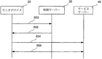
図2では、異なるデバイスの間の一般的なシグナリング方式が略図で示されている。デバイス間の通信の仕様は、使用される通信プロトコルおよび物理的ネットワークに応じて変わり得る。しかしながら、ネットワークを介し、一般的な通信をどのように実行するかに関する詳細については、コンピュータ通信の当業者には知られているので、この詳細については本明細書では説明しない。モニタデバイス20は、イニシエイション動作またはイニシエイション事象に応答し、モニタデバイス20内に記憶されているアドレスへ接続メッセージ600を送るようになっている。この接続メッセージは、前記アドレスに常駐する制御サーバー30で受信される。この制御サーバー30は、接続メッセージを受信し、モニタデバイス20と制御サーバー30とは、接続を設定する。制御サーバーは、モニタデバイス20から受信した通信信号から識別子も抽出する。この識別子は、モニタデバイスとサービスプロバイダおよびサービスサーバーとを照合するのに使用される。制御サーバー30が一致していると判断すると、この制御サーバー30はメッセージ602内のアドレスをモニタデバイスに送る。このメッセージは、モニタデバイス20でアドレスメッセージまたはリコンフィギュレーションメッセージの変更として識別される。このメッセージ602に応答し、モニタデバイス20は新しいアドレスを記憶し、接続メッセージ600または604を新しいアドレスに送る。接続サーバー30から受信されたアドレスは、システムの構造に応じ、別の制御サーバー30またはサービスサーバー40をアドレス指定できるが、これについては後述する。
In FIG. 2, a general signaling scheme between different devices is shown schematically. The specifications for communication between devices can vary depending on the communication protocol and physical network used. However, details regarding how to perform general communications over a network are known to those skilled in the art of computer communications and will not be described here. The
モニタデバイスで受信されたリコンフィギュレーションメッセージ602内のアドレスが、サービスサーバー40に関連しており、従って、モニタデバイス20から送られた次の接続メッセージ604がサービスサーバー40に送られると、サービスサーバー40とモニタデバイス20はサービス接続606を設定し、モニタデータのサービスサーバー40への伝送を可能にし、可能な場合にはモニタデバイスへのコンフィグレーションパラメータの伝送を可能にするが、このことは必ずしも必要ではない。こうして、モニタデバイス20はモニタサービスを提供することが可能にされたサーバーへ接続される。次に、モニタデバイス20が向けられたサービスサーバー40は、地理的なロケーション、ネットワーク内のロケーション、利用できるサービスおよび/または顧客固有の理由に関し、最も適当なサービスサーバー40となり得る。特定のモニタデバイス20に関して適用できるこれら基準のうちのいずれか1つを、制御サーバー30に提供されるデータにより制御してもよいし、または制御サーバー30がモニタデバイス20をサービスサーバー40に向けることによって制御してもよい。
The address in the
一実施例によれば、モニタデバイス20は図3Aおよび図3Bに示されるように入力手段202、処理手段204、不揮発性メモリ206、揮発性メモリ208、ネットワークインターフェース210、イニシエイション手段(initiating means)212、モニタデバイス手段216を含むことができる。図3aは、一般的なモニタデバイスの略図であり、図3bは、デジタルカメラであるモニタデバイス20の略図である。本発明の理解を容易にするために、図3aおよび3bは、正常な機能をデバイスが実行できるようにするのに必要なすべての手段を示しているわけではない。すなわちIR検出機能をIR検出器に実行させ、デジタルカメラ機能をデジタルカメラに実行させる手段のすべてを示しているわけではない。モニタデバイスをモニタデバイスとして作動させるのに必要なハードウェアおよびソフトウェアのようなすべての手段は、図3a内のモニタデバイス手段216により表示されており、図3bではカメラの対応する手段をビデオカメラ手段218と称す。通常のモニタデバイスネットワークをイネーブルするのに必要な手段および装置は、当業者に知られたものである。現在市販されている、かかるネットワークをイネーブルするモニタデバイスの一例として、スウェーデンS−223 69、ルンド、エンダラベーゲン14、アキシスコミュニケーションズAB社(Axis communications AB)から市販されている、ネットワーク接続されるデジタルカメラを挙げることができる。
According to one embodiment, the
上記のように、モニタデバイス20は複数のタイプのデバイスの任意のものでよく、モニタデバイス20の入力手段202は、異なるタイプのモニタデバイスである。例えば図3bのデジタルカメラ20aの入力手段202を、イメージセンサ、例えばCCDとすることができ、オーディオ検出器の入力手段をマイクなどとすることができる。入力手段202の主な機能は、モニタデバイス20がモニタする特性を検出し、サンプリングし、または測定し、よってかかるデータを別の処理のための処理手段204へ送ることである。
As described above, the
処理手段204は、モニタデバイスの機能を制御し、本発明の機能およびモニタデバイス20の一般的な機能に関連するプログラムコードを実行するようになっている。モニタデバイスの機能およびモニタシステムとの対話(interation)に関連するデータおよび情報を記憶するために、モニタデバイス20により不揮発性メモリ206を使用できる。特に本発明の一実施例によれば、この不揮発性メモリに、ネットワーク上のサーバーに対するアドレスのリスト214を記憶する。このアドレスのリスト214は優先マーカー(priority marker)によって各アドレスエントリーをマークすることにより優先度を決定できる。これらのマーカーは優先度を識別する番号とすることができる。メーカーから出荷されるモニタデバイス内のアドレスのリスト214は、制御サーバー30に対する少なくとも1つのあらかじめプログラムされたアドレスを含み、このサーバーは一般にこのアプリケーションにおける初期制御サーバー(initial control server)と称される。このリスト214は複数のアドレスを含むことができ、このリストでは、最高の優先度を有するとマークされたアドレスは、モニタデバイスが接続事象に応答し、接続メッセージを送る先の最初のアドレスである。この最初のアドレスが失敗した場合、優先リスト内の次のアドレスが試行され、接続メッセージが同じようにそのアドレスへ送られる。別の実施例によれば、最初のアドレスが失敗した場合、リスト214内で試行される次のアドレスがランダムに選択され、その結果、多くのデバイスに同じリストが設けられており、障害のあるアドレスに基本的に同時に接続しようとしている場合、ネットワーク内で負荷の分散が行われる。
The processing means 204 controls the functions of the monitor device and executes program codes related to the functions of the present invention and the general functions of the
この不揮発性メモリは、モニタデバイスをユニークに識別する識別コードおよび暗号化のためのユニークな鍵も含むことができる。制御サーバーまたはサービスサーバーにおいて、モニタデバイスを識別するのに使用でき、ユニークなキーは識別コードにより記述されるカメラとしてカメラを認証するのに使用できる。 This non-volatile memory may also include an identification code that uniquely identifies the monitoring device and a unique key for encryption. In the control server or service server, it can be used to identify the monitor device, and the unique key can be used to authenticate the camera as the camera described by the identification code.
処理手段204をサポートし、および/または制御サーバーから受信されたアドレスを一時的に記憶するのに、揮発性メモリ208を使用できる。従って、揮発性メモリ208は、処理手段204によりモニタデバイス204上で実行されるアプリケーションによって使用されるメモリでもよい。
ネットワークインターフェース210は、モニタデバイス20とネットワーク50との間のインターフェースであり、多数の異なるネットワークに対するネットワークインターフェース210を構成するのに使用できるハードウェアおよびソフトウェアは、コンピュータネットワークに精通する当業者には周知のものである。
The
イニシエイション手段212はイニシエイション事象を発生し、よって不揮発性メモリ206に記憶された優先アドレスへ初期接続メッセージを送ることをトリガーする手段である。一実施例によれば、イニシエイション手段212は、ネットワーク50へのモニタデバイス20の接続、すなわちネットワーク50への電源をオンしたモニタデバイス20の接続または既に物理的にネットワークに接続されているモニタデバイス20の電源の投入のいずれかを検出するようにイネーブルされた検出器である。かかるイニシエイション手段212を構成することにより、適当なサービスサーバー40のサーチおよびこれへの接続を完全に自動化できる。別の実施例によれば、イニシエイション手段212をモニタデバイス20の電源ボタンとしてもよいし、サービスサーバー40へのモニタデバイス20の接続をイニシエイトする専用のボタンとしてもよい。
Initiation means 212 is a means for triggering an initiation event and thus sending an initial connection message to the preferred address stored in
サービスサーバー40へのアドレスを含むメッセージまたはかかるサーバーへのアドレスを含むリコンフィギュレーションメッセージに応答し、制御サーバー30またはサービスサーバー40へ接続メッセージを送るようになっている手段218を、処理手段204によって実行されるプログラムコードによって実施してもよい。
不揮発性メモリ206に記憶されているユニークな鍵に関する説明に戻ると、この鍵は、送るべきメッセージの暗号化または受信したメッセージの解読のためにも使用できる。更にこの鍵を使って、スウェーデンS−223 69、ルンド、エンダラベーゲン14、アキシスコミュニケーションズAB社により出願された国際特許出願第WO2006/073348号に記載のようなオープンパスを生じさせる接続の設定中にカメラを認証することができる。この制御サーバーおよびサービスサーバーにはモニタデバイスからのメッセージを解読し、モニタデバイスに送られるメッセージを暗号化し、モニタデバイスを認証できるようにする鍵を設けることもできる。よって、モニタデバイスと制御サーバーおよび/またはサービスサーバーとの間のすべての通信を暗号化できる。製造される各モニタデバイスに対し、ユニークな鍵を設けることが好ましく、この鍵はデバイスの製造中にモニタデバイス内に記憶できる。これら鍵は、共有秘密システムの鍵、または公開鍵システムの鍵とすることができる。
Returning to the description of the unique key stored in
一実施例によれば、これら鍵を設けるべきカメラを製造する前に、異なる鍵の極めて大きいリストを作成する。このリストの大きさは、何年もの間、新しいリストを作成する必要のない大きさとすべきである。各制御サーバーには、鍵のリストを設け、モニタデバイスの製造中、デバイスにはこれら鍵のうちの1つが設けられることになる。このように鍵を設けることにより、安全上の危険を生じさせ得るような鍵を配布する必要がなくなる。従って、モニタデバイスの認証および鍵の配布を簡略化できる。 According to one embodiment, a very large list of different keys is created before manufacturing the camera to be provided with these keys. The size of this list should be such that there is no need to create a new list for many years. Each control server is provided with a list of keys, and during manufacture of the monitor device, the device will be provided with one of these keys. Providing keys in this way eliminates the need to distribute keys that can pose a safety risk. Therefore, authentication of the monitor device and key distribution can be simplified.
図4aには一実施例に係わる、サービスサーバー40を探すモニタデバイス20のプロセスが示されている。最初にオフラインまたはシャットオフされているモニタデバイス20をイニシエイトする。すなわちネットワークに接続し、電源をオンにするか、上記他の方法でイニシエイトする(ステップ620)。
FIG. 4a shows the process of the
次にモニタデバイス20は、不揮発性メモリ206内の優先リストから最初のアドレスを検索する(ステップ622)。このアドレスは、製造プロセス中にメーカーによって記憶されたアドレスとすることができる。しかしながら、本発明に係わるシステムにあらかじめモニタデバイス20が接続されている場合、このアドレスはデバイスの製造中にモニタデバイス20内に設けられたアドレスのサーバー以外の、より適当なサーバーに対するアドレスを含む、別のメッセージまたはリコンフィギュレーションメッセージに応答して記憶されたアドレスでもよい。
Next, the
次にモニタデバイスは検索されたアドレスに関連するサーバーへネットワークインターフェース210を介し、接続メッセージを送る(ステップ624)。
The monitoring device then sends a connection message via the
接続メッセージが送られた後にモニタデバイスは、接続メッセージを受信したサーバーからの応答を待つ。 After the connection message is sent, the monitoring device waits for a response from the server that received the connection message.
ステップ626において、応答が新しいサーバーへのアドレスを含むメッセージとなる場合、または応答が新しいサーバーへのアドレスを含むリコンフィギュレーションメッセージとなる場合、モニタデバイスは不揮発性メモリ206内にこのアドレスを記憶する(ステップ628)。このアドレスはリスト214内に、最も高い優先度のアドレスとして記憶できる。サーバーからの応答メッセージまたはリコンフィギュレーションメッセージは、特定の一実施例によれば、不揮発性メモリ206内の現在のリストの代わりとなるサーバーアドレスの完全に新しいリスト、または現在のリスト内のアドレスの一部に代わるアドレスのサブセットを含むことができる。
In
次に、モニタデバイスは新しいサーバーアドレスへ新しい接続メッセージを送る(ステップ630)か、または受信したメッセージに応答し、ステップ628でリストを変更した後に、優先リスト内の最初のアドレスを送る。次に、モニタデバイス20は、接続メッセージを送った先のサーバーからの応答をもう1回待つ。
The monitoring device then sends a new connection message to the new server address (step 630) or responds to the received message and sends the first address in the preference list after modifying the list in
ステップ626において応答メッセージ内に新しいサーバーアドレスが識別されない場合、応答が自らの内部のサービスサーバー40であるサーバーの表示を含むかどうかをモニタデバイス20がチェックする(ステップ632)。応答がかかる表示を含む場合、モニタデバイス20およびサービスサーバーはサービス接続を設定する(ステップ634)。
If no new server address is identified in the response message at
サーバーがサービスサーバーである表示を応答が含まない場合、モニタデバイスはサーバーからの別のメッセージを待つことができる。別の実施例では、応答メッセージがサーバーをサービスサーバーとして識別しないと判断したとき、または応答メッセージが新しいサーバーアドレスを識別しないと判断されたときに、モニタデバイスは接続メッセージを直接リスト内の別のアドレスに送る。別の実施例ではサーバーまたはアドレスがエラーである可能性が高い旨をカウンタまたはタイマーが表示した後に、リスト内の別のアドレスに、かかる接続メッセージが送られる。前記別のアドレスは、前に述べたように、優先リスト内の次のアドレスでもよいし、またはリスト内でランダム選択してもよい。 If the response does not include an indication that the server is a service server, the monitoring device can wait for another message from the server. In another embodiment, when the response message determines that the server does not identify the server as a service server, or when the response message determines that it does not identify a new server address, the monitoring device directly sends a connection message to another list in the list. Send to address. In another embodiment, such a connection message is sent to another address in the list after the counter or timer indicates that the server or address is likely to be in error. The other address may be the next address in the priority list, as described above, or may be randomly selected in the list.
図4Bに示される別の実施例では、モニタデバイスの不揮発性メモリからのサーバーアドレスを検索するステップ622は、更に識別コードおよび認証コードを検索することを含む。この識別コードは、モニタデバイスをユニークに識別する識別子、例えばシリアル番号、アイテム固有のコードと組み合わせた製品コードなどである。認証コードは不揮発性メモリ206内に記憶された鍵によって暗号化されたコードとすることができる。識別子および認証コードは、次に接続メッセージ(ステップ624)内、またはサーバー30との後の通信信号内のいずれかにおける検索されたアドレスのサーバー30へ送られる(ステップ625)。更に、新しいサーバーアドレスを含む制御サーバーからの応答は、第2認証コードも含むことができ、この第2認証コードはサービスサーバーに接続されたときにモニタデバイスを認証するのに使用できる。この認証コードは、制御サーバーが発生する暗号化/解読鍵とすることができる。この第2認証コードの目的は、メイン認証コードまたは鍵の分散を防止することである。その理由は、かかる分散によってコードの安全性が脅かされる可能性があるからである。
In another embodiment shown in FIG. 4B, retrieving 622 a server address from the non-volatile memory of the monitoring device further includes retrieving an identification code and an authentication code. This identification code is an identifier that uniquely identifies the monitor device, for example, a serial number, a product code combined with an item-specific code, or the like. The authentication code can be a code encrypted with a key stored in the
図5には、制御サーバー30の一実施例が略図で示されている。モニタデバイス20によって設定された自動接続は制御サーバーで分析され、制御サーバー30は、制御サーバーに利用できる他のサーバーの情報およびモニタデバイス20との通信で提供される情報に基づき、最も適切な新しいサーバーへのアドレスをモニタデバイス20に提供する。制御サーバー30は、ネットワーク通信を行うためのネットワークインターフェース310と、制御サーバー30を作動させるための処理手段312と、処理手段312が実行するアプリケーションプログラムをサポートし、記憶するためのメモリ314と、モニタデバイス20と制御サーバー30との間の通信からモニタデバイスの識別子を抽出するための識別抽出器316と、モニタデバイス20の識別コードを認証するための認証器317と、識別コードとサーバーとを照合するための照合手段318と、抽出された識別子に一致するサーバーに関連するアドレスを発生し、これを送るためのリコンフィギュレーションメッセージ発生器320とを含む。
In FIG. 5, one embodiment of the
識別抽出器316は、制御サーバー30に接続するモニタデバイスのアドレスを抽出することにより、制御サーバー30とモニタデバイスとの間の通信から識別子を抽出するようにでき、このアドレスは、例えばモニタデバイス20のIPアドレスとすることができる。このIPアドレスは、モニタデバイスが接続されているネットワークの運用者(operator)を識別するのに使用できる。各運用者は、割り当てられたシリーズのIPアドレスを有するので、このような識別が可能である。この抽出は、モニタデバイス20から発信されるメッセージに含まれる応答アドレスをピンポイントするようになっているIPアドレス322の抽出器によって実行される。別の実施例によれば、識別抽出器316は、制御サーバー30とモニタデバイス20との間の通信においてモニタデバイス20によって送られる識別コードおよび認証コードを抽出するようになっている識別コード抽出器324を含む。一実施例では、制御サーバー30はIPアドレス抽出器322および識別コード抽出器324の双方を含み、異なる方式に従ってこれらを使用できる。すなわち識別抽出器はデータベース330内のIPアドレスを抽出してそれがサーバーに関連しているかどうかのテストを開始でき、関連していない場合、識別コードチェックを続けるか、または識別抽出器は識別コードの、そして次にIPアドレスの抽出およびテストを開始するようになっている。
The
照合手段318は、識別抽出器316が抽出した識別子を活用し、モニタデバイスに最も適したサーバーを探す。この照合手段318は、識別子のリストまたはデータベース330および関連するサーバーにアクセスすることにより、モニタデバイスの識別子とサーバーとを照合するようになっている。リストまたはデータベースのアクセスは、データベースアクセス手段326によって行われる。照合に使用されるリストまたはデータベース330は、サーバーへの周辺機器としてサーバー内に配置してもよいし、またはネットワークを介してアクセスするようにもできる。後者の実施例は図5に示されている。リストまたはデータベース330は一実施例によれば、識別子のエントリーを含むことができ、各識別子は、少なくとも1つの制御サーバーまたはサービスサーバーに関連する。リストまたはデータベース330は、モニタデバイス20を認証するための各識別子に関連する鍵も含むことができる。当業者にはリストまたはデータベース330の別の構造も知られている。
The
リストまたはデータベース330にアクセスすることにより、モニタデバイス20の識別子と、鍵と、モニタデバイス20の識別子および鍵を制御サーバーまたはサービスサーバーに関連付ける情報のエントリーを含むデータベース330またはリストを編集できる。データベース330またはリストは、だれかが編集できるようにするためには認証を必要とし得る。リストまたはデータベース330のかかる編集は、多くの異なる方法で実行できる。例えばモニタデバイスの製造に関連してこの編集を実行でき、かかる場合、モニタデバイスの識別コードを入力し、所定のサービスプロバイダまたはサービスプロバイダのサーバーと関連付ける。編集は、サービスプロバイダのサーバーのうちの1つまたは一組に関連付けるべきモニタデバイスの識別コードをサービスプロバイダが入力することによって実行でき、この編集はサービスプロバイダがプロバイダのネットワークのIPアドレスを入力することによって実行でき、編集はこれらアドレスとプロバイダのサーバーのうちの1つまたは一組とを関連付けできる。
By accessing the list or
図6aには、モニタデバイスにサービスする制御サーバー30のプロセスの一実施例が示されている。制御サーバー30は、ネットワークおよびネットワークインターフェース310を介し、モニタデバイス20からの接続メッセージを受信する(ステップ710)。モニタデバイス20および制御サーバー30は、通信のための接続を設定する(ステップ712)。次に、制御サーバー30の識別抽出器316は、通信からモニタデバイスに関連する識別子および認証コードを抽出する(ステップ714)。次に、認証コードの手段により、識別子の認証をチェックする(ステップ715)。認証に失敗した場合、プロセスを終了する(ステップ717)。失敗しなかった場合、識別子と、この特定の実施例ではサービスプロバイダとを照合する照合手段318により、識別子を処理する(ステップ716)。
In FIG. 6a, one embodiment of the process of the
サービスプロバイダが識別子と一致しなかった場合(718)、制御サーバー30はエラーメッセージを発生でき(ステップ720)、接続メッセージに応答し、モニタデバイス20へこのメッセージを戻す。モニタデバイス20は、特定のエラーコードをディスプレイするか、または一部のLEDを附勢し、エラーのタイプを表示するようにできる。
If the service provider does not match the identifier (718), the
かかるエラーが発生した場合、ユーザーはどの当事者がサポートを提供するかに応じ、モニタデバイスまたはサービスプロバイダのサポートを通知でき、これら当事者はモニタデバイス20に関連した正しいアドレスまたはモニタデバイス20のIPアドレスを入力し、データベース内にモニタデバイスの識別子を入力し、これをサーバーなどに関連付けできる。
If such an error occurs, the user can notify the monitoring device or service provider's support, depending on which party provides support, and these parties can provide the correct address associated with the
ステップ718において、サービスプロバイダが識別子に一致している場合、照合手段317は、そのサービスプロバイダのサーバーへのアドレスを検索する(ステップ722)。
In
次に、リコンフィギュレーションメッセージ発生器320へ検索されたサーバーアドレスが送られ、メッセージ発生器は検索されたサーバーアドレスを含むリコンフィギュレーションメッセージまたは別のタイプのメッセージを発生する(ステップ724)。次にステップ726で、リコンフィギュレーションメッセージがモニタデバイス20へ送られ、モニタデバイスは図3〜4を参照してこれまで説明したように、リコンフィギュレーションメッセージに作用する。制御サーバー30は、モニタデバイス20へ送るための第2認証コードも発生でき、この認証コードはリコンフィギュレーションメッセージに関連し、ステップ726でモニタデバイス20へ送ることができる。第2認証コードは、サービスサーバーへの接続時にモニタデバイスを認証するのに使用できる。この認証コードは制御サーバーが発生する暗号化/解読鍵とすることができる。この第2認証コードの目的は、メイン認証コードまたは鍵の分散を防止することである。その理由は、かかる分散がコードの機密性を犯す恐れがあるからである。
Next, the retrieved server address is sent to the
図6aに表示されているプロセスは、初期制御サーバー内で実施することが好ましい。すなわちモニタデバイスの製造中に、モニタデバイスに入れられたアドレスによってアドレス指定される制御サーバーのタイプにより実施することが好ましい。かかる制御サーバーはモニタデバイスのメーカーによって制御でき、かかる制御サーバーは、デバイスをだれが買うか、モニタデバイスに関連するのはどのサービスプロバイダであるかとは無関係に、同じプロセス、プログラムおよびプロパティを使って、メーカーが大きなシリーズのモニタデバイスを構成することを可能にできるという利点を提供できる。最初に制御サーバー30に接続されるときに、モニタデバイスのプログラムおよびプロパティを自動的に変更し、サービスプロバイダまたはデバイスに関連する他の当事者からの特定のリクエストに従ってカスタム化することができる。かかる自動変更はリコンフィギュレーションメッセージ内でモニタデバイス20へ送られる。
The process displayed in FIG. 6a is preferably performed in the initial control server. That is, during the manufacture of the monitor device, it is preferably implemented according to the type of control server addressed by the address entered in the monitor device. Such a control server can be controlled by the manufacturer of the monitoring device, which uses the same processes, programs and properties, regardless of who buys the device or which service provider is associated with the monitoring device. , Providing the advantage of allowing manufacturers to configure large series of monitor devices. When initially connected to the
図6bに示されるように制御サーバーのプロセスの別の実施例を構成でき、このプロセスは図6aの実施例のプロセスに類似するので、図6aのプロセスと同じステップに対して同じ参照番号を使用する。異なるステップも同じ参照番号を使用するが、番号の後に’記号をつける。従って、図6bのプロセスは、最初にサービスプロバイダを照合することによるサーバーの照合をせずに、サーバーは識別子に直接照合されるという点が違う。従って、抽出された識別子とデータベース内のサーバーとが照合される(ステップ718’)。サーバーが見つかった場合(ステップ718’)一致したサーバーに関連するサーバーアドレスが検索される(ステップ722’)。このプロセスの他の部分は図6aのプロセスと同一である。 Another embodiment of the control server process can be configured as shown in FIG. 6b, which is similar to the process of the embodiment of FIG. 6a, and therefore uses the same reference numerals for the same steps as the process of FIG. 6a. To do. Different steps use the same reference number, but with a 'sign after the number. Thus, the process of FIG. 6b differs in that the server is matched directly against the identifier without first matching the server by matching the service provider. Accordingly, the extracted identifier is checked against the server in the database (step 718 '). If a server is found (step 718 '), the server address associated with the matched server is retrieved (step 722'). Other parts of this process are identical to the process of FIG. 6a.
図5、6aおよび6bを参照して説明したサーバーに類似した制御サーバー30は、初期制御サーバー30として使用できる。更にかかる制御サーバー30は、後のステージの制御サーバー30として有効である。すなわちすべてではないにしても、初期制御サーバー30によって利用されるデータベース330内にサービスプロバイダのサービスサーバーのアドレスを記憶した場合、初期制御サーバー30がアドレスを提供できるサブシステム内に配置された制御サーバー30、またはサービスプロバイダの制御サーバー30として有効である。このように、異なる当事者がそれらの目的に従って異なる組のサーバーを管理できる。例えばモニタデバイスのメーカーが一組の初期制御サーバーを管理し、サービスプロバイダがサービスサーバーおよび可能な場合には一部の制御サーバーを管理する場合、メーカーはサービスプロバイダおよびサービスプロバイダのサーバーのサブセットの追跡を維持するだけでよく、一方、サービスプロバイダはデータベースおよびメーカーの制御サーバーへの変更を検討することなく、サービスサーバーを設定することが認められる。
A
システム内のサービスサーバー40は、モニタデバイス230とユーザーターミナルとの間でユーザーインターフェースを提供するサーバーと見なすことができる。このサービスサーバー40は、モニタデータをサービスサーバーに転送するためにモニタデバイスへサービス接続するようになっている。更に、このサービスサーバーはモニタデバイス20から受信したデータを処理し、そのデータを提供するか、またはユーザーのクライアントが提供することを可能にするようになっている。サービスプロバイダ40は、モニタデバイスを制御するようにもできる。サービスサーバーは、例えばモニタデバイスと通信し、ユーザーターミナル、例えばクライアントコンピュータ、モバイル電話などと通信するための通信手段を含むサーバーとし得る。更に、サービスサーバーは認証されたユーザーだけをモニタデバイスに接続するための認証手段を含むことができる。この認証は、標準的なユーザーネームおよびパスワードのログインとして実行できる。発送時にモニタデバイスと共にまずユーザーネームおよびパスワードを提供できる。更に、サービスサーバーはモニタデバイスからのモニタ情報を記憶するデータベースを含むことができる。かかるモニタデバイスは、カメラからのビデオシーケンス、例えばドア内のIR検出器またはセンサからのアラームをトリガーすることに関連する事象とすることができる。このサービスサーバーはユーザーターミナルからのリクエストおよび認証時にカメラからユーザーターミナルへ実質的にライブのビデオストリームを送るようにもできる。
The
アクセス制限デバイス、例えばファイアーウォール、NAT(ネットワークアドレス変換)、ダイナミックアドレスを提供するISP(インターネットサービスプロバイダ)の背部に配置されたモニタデバイスへ制御パラメータ、データ、更新などの送信を達成するために、サービスサーバー40はモニタデバイスから送られたリクエストに応答し、かかる情報を送るようにできる。モニタデバイス20は通信を開始するようになっているので、このことを容易に達成できる。
To achieve the transmission of control parameters, data, updates, etc. to a monitoring device located at the back of an access restriction device such as a firewall, NAT (Network Address Translation), ISP (Internet Service Provider) that provides dynamic addresses, The
一実施例では、サービスサーバー(図7参照)は、ネットワーク50を通してモニタデバイスとの通信を可能にするネットワークインターフェース410と、サービスサーバーでアプリケーションを実行するための処理手段412と、アプリケーションデータを記憶するためのメモリ414と、モニタデータ提示手段416とを含む。サービスサーバーは、モニタデバイス20とサービスサーバー40との間の通信からモニタデバイスの識別子を抽出するための識別抽出器418と、モニタデバイス20の識別コードを認証するための認証器234も含むことができ、サービスサーバー内の認証のために使用される認証コードは前記第2認証コードとすることができる。識別抽出器は更に、IPアドレス抽出器420および/または制御サーバー30内と同じ機能性を有する識別コード抽出器422を含むことができる。モニタデータ提示手段416は、1つまたは複数のモニタデバイスからのモニタデータのプレゼンテーションをイネーブルするための、1つまたは複数のアプリケーションを備える。モニタデータを受信し、このデータを処理し、ユーザーのためのデータを提示する可能性を提供するサービスサーバーは、当業者に知られたものである。使用可能なサービスサーバー40の一例は、スウェーデン、S223 69 ルンド、エンダラベーゲン14、アキシスAB社により出願された国際特許出願第WO2006/073348号に記載されており、この出願は、アクセス制限デバイスを介した通信のための方法についても述べている。
In one embodiment, the service server (see FIG. 7) stores a
図8には、サービスサーバーの発明に関連するプロセスの一実施例が示されている。このサービスサーバー40は、モニタデバイス20から接続メッセージを受信し(ステップ810)、モニタデバイスを識別し、認証する(ステップ811)。次にサービスサーバーとモニタデバイスとがサービス接続を設定する(ステップ812)。サービス接続が設定されると、サービスサーバー40は、サービスサーバー40の条件または最終ユーザーの要求に従って、モニタデバイスからのモニタデータの受信(ステップ814)、および受信したモニタデータの処理(ステップ816)をスタートできる。次に、サービスサーバー40は、ユーザーのクライアントのために提示するための、またはクライアントもしくはユーザーのサーバーにダウンロードするためのモニタデータを記憶できる(ステップ818)。クライアントはワークステーションコンピュータ、デスクトップコンピュータ、ラップトップコンピュータ、ハンドヘルドコンピュータ、例えばPDA(パーソナルデジアルアシスタント)、モバイル電話などでよい。
FIG. 8 shows an embodiment of a process related to the invention of the service server. The
モニタデバイスをサービスサーバーに接続するためのシステムは、複数のモニタデバイス20と、複数の制御サーバーと、複数のサービスサーバーとを含むことができる。モニタデバイスはネットワーク50に直接、別のネットワークを介し、アクセス制限デバイスなどを介して接続できる。
A system for connecting a monitor device to a service server can include a plurality of
図9において、このシステムの一例は、3つのモニタデバイス20〜22、2つのサービスサーバー40〜41およびユーザーターミナル42および44を含む。この例では、視覚的に異なるように見たカメラの2つの図およびモニタデバイスを示す1つの一般的なボックスを使用することにより、モニタデバイスのうちの2つをモニタカメラとして示している。我々はこのシステムにおけるモニタデバイスは、ブランド、タイプまたはモニタ機能に関して必ずしも同一でないことを強調したい。すなわちモニタシステムはIR検出器、広角カメラ、低解像度カメラを同時に含むことができる。図9に示された例では、モニタデバイス20〜22の数だけでなく、サービスサーバー40〜41の数も容易に増加してもよい。更に、このシステム例は、メーカーによって制御される制御サーバーとすることができる制御サーバー30を含む。
In FIG. 9, an example of this system includes three monitor devices 20-22, two service servers 40-41, and
更に、モニタデバイス22のうちの1つはアクセス制限デバイス60、例えばファイアーウォール、NAT(ネットワークアドレス変換)サーバー、ダイナミックアドレスを提供するISP(インターネットサービスプロバイダ)、ファイアーウォールを介し、ネットワークに接続されている。かかるアクセス制限デバイスは、例えばモニタデバイスからのメッセージまたはリクエストに応答し、情報または命令を提供することにより、かかるデバイスを通過するようにモニタデバイスへ情報または命令を送るようになっているので、サーバーからのモニタデバイスのアクセスを制限しない。例えばモニタデバイスの各々とサーバーとの照合プロセス中に制御サーバー30がアクセスするデータベースは、モニタデバイス20のIPアドレスがサービスサーバー40に提供するインターネットアクセスプロバイダのIPアドレスであるという事実に基づき、モニタデバイス20のIPアドレスをサービスサーバー40に関連付ける情報を含むことができる。更に、またはこれとは異なり、データベースはモニタデバイス21および22の各々から送られた識別コードと、サービスサーバー41とを関連付ける情報を含むことができる。従って、制御サーバーのデータアドレスがモニタデバイス20〜22とそれらのサービスサーバーとを関連付ける情報を含む場合、制御サーバー30は、モニタデバイスの各々が送る接続メッセージに応答し、サービスサーバー40のアドレスをモニタデバイス20へ送り、サービスサーバー41のアドレスをモニタデバイス21および22へ送ることができる。前に説明したように、モニタデバイスで受信したアドレスを不揮発性メモリに記憶し、将来のイニシエイション時に使用することができる。例えばモニタデバイス20の接続が外されており、再接続された場合にサービスサーバー40のアドレスを不揮発性メモリに記憶し、モニタデバイスが接続メッセージを制御サーバー30に送る代わりに直接、サービスサーバー40へ送ることができる。ユーザーターミナル42および44は、ネットワークを介してサービスサーバーと通信し、カメラからのモニタ情報または画像シーケンスを入手するか、またはモニタデバイスを制御するようになっている。アクセス制限デバイス、例えばファイアーウォールを介してネットワークにモニタデバイスが接続されている場合、サービスサーバー40のようなサーバーを介し、モニタデバイスにアクセスしなければならない。
In addition, one of the
図10では、更に別の可能なコンフィギュレーションが示されている。この場合、すべてが保護された60の個人ネットワーク51に接続されているような、自らの建物をモニタするために多数のモニタデバイス20を必要とする会社はサービスサーバーを直接個人ネットワーク51にも接続すると仮定できる。ユーザーターミナル42および44は、提供されるモニタサービスにアクセスするため、および/またはユーザーのモニタデバイスにアクセスするために、サービスサーバーに接続されている。モニタデバイス20を購入したとき、これらデバイスは制御サーバーに登録されており、会社の内部サービスサーバーのアドレスに関連するカメラのシリアル番号を取り込むことができ、制御サーバーは初期制御サーバーとなり得る。このように、カメラの設置は大幅に簡略化される。その理由は、モニタデバイス20を取り付け、個人ネットワーク51に接続するだけでよく、モニタデバイス20は自動的に制御サーバー30により、使用を意図するサービスサーバー40を探し、これに接続するようにリコンフィギュアされるからである。
In FIG. 10, yet another possible configuration is shown. In this case, a company that requires a large number of
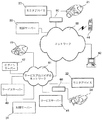
図11において、システムの更に別のコンフィギュレーションが示されている。モニタサービスプロバイダのサービス、例えばネットワークアクセス、すなわちインターネットアクセスのプロバイダであると仮定する。メーカーの制御サーバー30に関連するデータベースにIPアドレス、IPアドレスの一部または複数のIPアドレスが記憶される。すなわち制御サーバー30のデータベースにIPアドレスの多数の情報、またはサービスプロバイダのIPアドレスに接続されているとしてモニタデバイスを識別するのに必要な多数のIPアドレスがロードされる。サービスプロバイダは制御サーバー31にも関連しており、制御サーバー31はサービスプロバイダによって運用される制御サーバーである。サービスプロバイダは何らかの理由から、2つのサービスサーバー40および41をインストールしている。
In FIG. 11, yet another configuration of the system is shown. Suppose that you are a service of a monitor service provider, for example a provider of network access, ie internet access. An IP address, a part of the IP address, or a plurality of IP addresses are stored in a database associated with the manufacturer's
サービスプロバイダの制御サーバー31にはサービスサーバーによって維持されるデータベースが提供され、このデータベースには各モニタデバイス22〜25をサービスサーバー40〜41のどれに(即ち、どの1つに)接続しなければならないかに関する情報を含む。モニタデバイス22〜25を制御サーバー31内のサービスサーバー40〜41に関連付ける情報は、上記のようにIPアドレスに基づいていもよいし、または特定のモニタデバイスを識別するユニークなコードに基づいてもよい。従って、モニタデバイス24がサービスプロバイダ52のネットワークに接続されるとき、モニタデバイスはサービスプロバイダ52のネットワークおよび別のネットワーク50を介して制御サーバー30へ接続メッセージを送る。ネットワーク50は制御サーバーが接続される相手の先のインターネット、LAN、WANまたは他の任意のネットワークでよい。
The service provider's
制御サーバー30は、例えばIPアドレスと、サービスプロバイダおよび制御サーバー31とを照合し、制御サーバー31に関連するアドレスをモニタデバイス24へ送る。次にモニタデバイス24は接続メッセージを制御サーバー31へ送る。次に、制御サーバー31はIPアドレスまたは別の識別子とサービスサーバー41とを照合し、サービスサーバー41に関連するアドレスをモニタデバイス24へ送る。次に、モニタデバイス24は接続メッセージをサービスサーバー41へ送り、サービスサーバー41によりサービス接続を設定できる。
For example, the
モニタデバイス25および22は、サービスプロバイダおよびサービスプロバイダの制御サーバー31に同じように関連させることができる。しかしながら、制御サーバー31は制御サーバー31のデータベース内のエントリーに応じ、モニタデバイス25および22の各々とサービスサーバー40および41の任意のいずれか1つとを関連付けできる。モニタデバイスを特定のサービスサーバーに関連付ける理由は様々であってよい。1つの理由は、中小企業に対しては、あるサービスサーバーを提供し、より安価なホームソリューションに対しては、あるサービスサーバーを提供し、大企業に対しては、あるサービスサーバーを提供し、可能な場合にはカスタムアプリケーションを構成するからである。
The
2つのモニタデバイス20および21は、サービスプロバイダのネットワークを介し、共通ネットワーク、例えばインターネットに接続されることはない。図では、これらモニタデバイスを何らかの方法でサービスプロバイダに関連付けできる。例えば制御サーバー30は、制御サーバー30とモニタデバイスの各々との間の通信中に、制御サーバー30へ送られた識別子により使用するためのサービスプロバイダを識別できる。
The two
図11は、サービスプロバイダのネットワーク51に接続されたログインサーバー62も開示している。ユーザーがサービスプロバイダに識別コードおよびユーザー認証コードを提供し、サービスプロバイダが、サービスプロバイダに対する識別コードにより識別されたモニタデバイスに関連付けるための命令と共に、識別コードおよびユーザー認証コードを制御サーバー30へ送るようになっている実施例において、ログインサーバー62を使用する。認証コードの目的は、モニタデバイスに対するアクセスの不正な関連付けを禁止することである。ログインサーバー62はスタンドアローンデバイスとすることができる。しかしながら、サービスプロバイダのサービスサーバー40、41または制御サーバー31内で構成することも可能である。
FIG. 11 also discloses a
図12では、サービスサーバーにモニタデバイスを接続し、ユーザーがモニタデバイスにアクセスするためのシナリオの一例が示されている。このシナリオでは、モニタデバイスを製造し、製造プロセスにおいてモニタデバイス内にユニークな識別コードおよびユニークな鍵を記憶する(ステップ810)。この識別コードおよびユニークな鍵については、本明細書において前に記載したものである。メーカーは、制御サーバーのデータベース内に識別コードおよびユニークな鍵も記憶する(ステップ812)。次に、インターネットアクセスのオペレータまたは監視ソリューションを提供する会社に対し、制御サーバーのデータベース内で識別コードをユニークな鍵を関連付ける(ステップ814)。これら会社のうちのいずれかに対するモニタデバイスの関連付けは、会社がモニタデバイスを購入した結果、または契約の結果として行われる。次に、ユーザーはカメラを購入し、恐らく監視サービスの一部としてモニタデバイスに関連する会社を取り扱い、カメラをネットワークに接続する(ステップ816)。モニタデバイス、制御サーバーおよびサービスサーバーは、本明細書で前に説明した実施例のうちのいずれかのステップを実行し、最終的にサービスサーバーへのサービス接続を行う(ステップ818)。サービス接続が起動され、作動すると、ユーザーはサービスの口座またはモニタデバイスを識別することにより、ユーザーターミナルからサービスサーバーへログインできる(ステップ820)。ユーザーはユーザー認証コードなどと組み合わせたモニタデバイスの識別子を入力することにより、ユーザーネームおよびユーザー認証コードを入力することによりログインできる。ユーザーがログインすると、ユーザーはサービスサーバー内に記憶されたモニタデバイスからデータにアクセスし、モニタデバイスからライブのデータにアクセスするか、またはモニタデバイスに命令を送ることができる。 FIG. 12 shows an example of a scenario for connecting a monitor device to a service server and allowing a user to access the monitor device. In this scenario, a monitor device is manufactured and a unique identification code and a unique key are stored in the monitor device during the manufacturing process (step 810). This identification code and unique key have been previously described herein. The manufacturer also stores an identification code and a unique key in the control server database (step 812). Next, a unique key is associated with the identification code in the control server's database to the Internet access operator or company providing the monitoring solution (step 814). The association of the monitor device with any of these companies is performed as a result of the company purchasing the monitor device or as a result of a contract. Next, the user purchases the camera, handles the company associated with the monitor device, possibly as part of the monitoring service, and connects the camera to the network (step 816). The monitoring device, control server, and service server perform any of the steps of the embodiments previously described herein and ultimately make a service connection to the service server (step 818). Once the service connection is activated and activated, the user can log into the service server from the user terminal by identifying the service account or monitoring device (step 820). The user can log in by inputting the user name and the user authentication code by inputting the identifier of the monitor device combined with the user authentication code. When the user logs in, the user can access data from the monitor device stored in the service server, access live data from the monitor device, or send instructions to the monitor device.
図13において、サービスサーバーにモニタデバイスを接続し、ユーザーがモニタデバイスにアクセスできるようにするためのシナリオの別の例が示されている。このシナリオでは、モニタデバイスを製造し、製造プロセスにおいてユニークな識別コードおよびユニークな鍵をモニタデバイス内に記憶する(ステップ910)。識別コードおよびユニークな鍵については、本明細書で既に説明した通りである。メーカーも、制御サーバーのデータベース内に識別コードおよびユニークな鍵を記憶する(ステップ912)。ユーザーはカメラを購入し、これをネットワークに接続する(ステップ914)。ユーザーはカメラが提供する識別コードおよびユーザー認証コードを使ってサービスプロバイダのサイトにもログインする(ステップ916)。サービスプロバイダによって識別コードおよびユーザー認証コードが受信されると、サービスプロバイダはユーザーが入力した識別コードおよびユーザー認証コードを含む命令を制御サーバーに送り、識別コードに関連し、認証コードに対して有効な鍵を有するモニタデバイスを、命令を送信したサービスプロバイダに関連付ける(ステップ918)。ステップ916および918の後で、モニタデバイスをネットワークに接続するステップ914を実行できる。モニタデバイス、制御サーバーおよびサービスサーバーは、本明細書の前で説明した実施例のうちのいずれかのステップを実行し、最終的にサービスサーバーへのサービス接続を行う(ステップ818)。サービス接続が起動され、作動すると、ユーザーはサービスの口座またはモニタデバイスを識別することにより、ユーザーターミナルからサービスサーバーへログインできる(ステップ820)。ユーザーはユーザー認証コードなどと組み合わせたモニタデバイスの識別子を入力することにより、ユーザーネームおよびユーザー認証コードを入力することによりログインできる。ユーザーがログインすると、ユーザーはサービスサーバー内に記憶されたモニタデバイスからデータにアクセスし、モニタデバイスからライブのデータにアクセスするか、またはモニタデバイスに命令を送ることができる。
In FIG. 13, another example of a scenario for connecting a monitor device to a service server and allowing a user to access the monitor device is shown. In this scenario, a monitor device is manufactured and a unique identification code and a unique key in the manufacturing process are stored in the monitor device (step 910). The identification code and the unique key are as already described in this specification. The manufacturer also stores the identification code and unique key in the control server database (step 912). The user purchases a camera and connects it to the network (step 914). The user also logs into the service provider's site using the identification code and user authentication code provided by the camera (step 916). When an identification code and user authentication code are received by the service provider, the service provider sends an instruction including the identification code and user authentication code entered by the user to the control server and is associated with the identification code and valid for the authentication code. The monitor device having the key is associated with the service provider that sent the instruction (step 918). After
図14にはサーバーから別のサーバーにモニタデバイスをハンドオーバーする一例が示されている。本願に関連し、モニタデバイスのハンドオーバーとは、モニタデバイスと通信中のサーバーがモニタデバイスにアドレスを提供し、モニタデバイスが受信したアドレスのサーバーに接続メッセージを送り、よってモニタデバイスが前のサーバーによって与えられた新しいサーバーと通信し始めることである。この図では、各矢印は、矢印が生じているサーバーが矢印の先のサーバーのアドレスをモニタデバイスに送り、次にモニタデバイスが接続メッセージをこのサーバーに送ることを示している。 FIG. 14 shows an example in which the monitor device is handed over from one server to another. In the context of this application, monitoring device handover refers to a server communicating with a monitoring device providing an address to the monitoring device and sending a connection message to the server at the address received by the monitoring device, so that the monitoring device is the previous server. Is to start communicating with the new server given by. In this figure, each arrow indicates that the server in which the arrow originates sends the address of the server to which the arrow is directed to the monitoring device, and then the monitoring device sends a connection message to this server.
図12から、多数の異なる構造を構成するのに本発明のシステムを使用できることが、図12から明らかであり、これら構造は必要であれば容易に変更できる。理解を容易にするために、図には限られた数のサーバーが示されているが、サーバーのうちの少なくとも一部は、恐らく図に示されている数よりも多いサーバーへの言及を含むことができる。 From FIG. 12, it is clear from FIG. 12 that the system of the present invention can be used to construct a number of different structures, which structures can be easily modified if necessary. For ease of understanding, the figure shows a limited number of servers, but at least some of the servers probably contain references to more servers than shown in the figure be able to.
図12の構造例では、システムは2つの初期制御サーバーを含む。例えば制御サーバー30:1と、制御サーバー30:2を含む。これらサーバーの双方は、初期のメーカーのサーバーでよい。すなわち製造中にモニタデバイス内にあらかじめプログラムされたアドレスを有するサーバーでよい。制御サーバー30は、本発明による制御サーバー30以外のサーバーとしては働かないようになっているサーバー、例えば制御サーバー30:1でよいが、制御サーバーは他のタスクを同時に実行してもよい。すなわち制御サーバーは、別のタイプのサーバーとして同時に、かつ別の目的のために働くことができる。更に、前に説明したように、制御サーバーは同じサイト、同じ部屋または同じキャビネット内に配置されたサービスサーバー40を有する制御サーバー30として、例えば制御サーバー30:2、30:3および30:6として構成できる。更に、制御サーバー30は組み合わせた制御サーバー30およびサービスサーバー40として、例えば制御サーバー30:4、30:7として構成できる。更に、初期制御サーバー30は、図には示されていない組み合わされた制御サーバー30とサービスサーバー40として構成できる。
In the example structure of FIG. 12, the system includes two initial control servers. For example, it includes a control server 30: 1 and a control server 30: 2. Both of these servers may be servers from early manufacturers. That is, it may be a server having an address pre-programmed in the monitor device during manufacture. The
上記のように、制御サーバー30:1および30:2の双方は、モニタデバイスのメーカーまたはかかるモニタシステムのサービスおよび管理全体を提供することに関心を有する他の当事者によって管理される初期制御サーバー30でよい。図12およびシステムの機能および利点の理解を容易にするために、制御サーバーからのハンドオーバーのパスをフォローする。モニタデバイスはインストールされ、イニシエイトされる際に自動的に制御サーバー30:1に接続される。すなわち制御サーバー30:1のアドレスは、デバイスの製造に関連し、モニタデバイス内に記憶されたアドレスのリストの最優先度アドレスとなっている。この例では、制御サーバー30:1に関連するデータベースだけが、2つのエントリーを含む。一方のエントリーは、サービスプロバイダの制御サーバー30:3へのアドレスを含み、他方のエントリーは、サービスプロバイダの制御サーバー30:4へのアドレスを含む。モニタデバイスの識別子とサービスプロバイダの制御サーバー30:3とが一致していると仮定する。この場合、制御サーバー30:1は制御サーバー30:3のアドレスをモニタデバイスに送り、モニタデバイスは制御サーバー30:3に接続メッセージを送る。サービスプロバイダの制御サーバー30:3において、モニタデバイスの識別子と、データベース、このときはサービスプロバイダのデータベース内のエントリーとをもう1回照合する。モニタデバイスと最も適したサービスサーバー40:1〜40:3、または更に別の制御サーバー30:6〜30:7とを照合する。これらサーバーは、図のハンドオーバーの矢印に従って使用できるサーバーである。この例では、制御サーバーとモニタデバイスをサービスサーバー40:3とを照合し、このサービスサーバーのアドレスをモニタデバイスに送る。次にモニタデバイスおよびサービスサーバーは上記のようにサービス接続を設定する。
As mentioned above, both control servers 30: 1 and 30: 2 are managed by the
モニタシステムにはバックアップサーバー、例えばシステム内に冗長性を提供する制御サーバーを容易に、かつ好ましく設けることができる。かかるバックアップサーバーはすべてのレベルで構成できる。例えば初期制御サーバーおよびより低いレベルの制御サーバーの双方に対して構成できる。このバックアップサーバーは専用バックアップサーバーでもよいし、通常別の領域または他のユーザーにサービスする制御サーバーでもよい。 The monitor system can be easily and preferably provided with a backup server, for example, a control server providing redundancy in the system. Such backup servers can be configured at all levels. For example, it can be configured for both the initial control server and the lower level control server. This backup server may be a dedicated backup server or a control server that normally serves another area or other users.
Claims (18)
モニタデバイスが、制御サーバーに関するアドレスを前記モニタデバイスのメモリから検索するステップと、
前記モニタデバイスが、前記モニタデバイスで生じた接続事象に応答し、制御サーバーに関連するアドレスに前記モニタデバイスからの接続メッセージを送るステップと、
前記モニタデバイスと前記制御サーバーとが、前記モニタデバイスと前記制御サーバーとの間の接続を設定するステップと、
前記モニタデバイスが、前記モニタデバイスをユニークに識別するための識別子を前記モニタデバイスのメモリから検索するステップと、
前記モニタデバイスが、前記識別子を前記モニタデバイスから前記制御サーバーに送るステップと、
識別抽出器が、前記制御サーバーにおいて、前記モニタデバイスをユニークに識別する前記識別子を前記接続メッセージから抽出するステップと、
照合手段が、識別子のデータベースおよび関連するサーバーにアクセスすることにより、前記抽出した識別子とサービスサーバーとを照合することにより、前記制御サーバーにおいて、前記モニタデバイスをユニークに識別するための前記識別子に関連するサービスサーバーを識別し、前記モニタデバイスをユニークに識別するための前記識別子に関連するサービスサーバーへのアドレスを検索するステップと、
リコンフィギュレーションメッセージ発生器が、前記サービスサーバーへのアドレスと、サービスプロバイダーまたは前記デバイスに関連する他の当事者からの特定のリクエストに従ってカスタム化するための前記モニタデバイスのためのプログラムとを有するリコンフィギュレーションメッセージを発生させかつ送るステップと、
前記モニタデバイスが、前記サービスサーバーへのアドレスの受信に応答し、前記モニタデバイスから前記サービスサーバーへ、接続メッセージを送るステップと、
前記モニタデバイスと前記サービスサーバーとが、前記モニタデバイスと前記識別されたサービスサーバーとの間にサービス接続を設定するステップとを備える方法。A method for reconfiguring a monitoring device, comprising:
A monitor device retrieving an address for the control server from the memory of the monitor device;
The monitoring device responding to a connection event occurring at the monitoring device and sending a connection message from the monitoring device to an address associated with a control server;
The monitor device and the control server setting up a connection between the monitor device and the control server;
The monitor device retrieving an identifier for uniquely identifying the monitor device from a memory of the monitor device;
The monitoring device sending the identifier from the monitoring device to the control server;
An identifier extractor extracts from the connection message the identifier that uniquely identifies the monitoring device at the control server;
Verification means, by accessing the database and associated server identifier, by collating the identifier and service server and the extraction, in the control server, the identifier for identifying the monitoring device uniquely Retrieving a service server associated with the service server associated with the identifier for uniquely identifying the monitor device ; and
A reconfiguration message generator having an address to the service server and a program for the monitoring device to customize according to a specific request from a service provider or other party associated with the device Generating and sending an action message;
A step of said monitoring device, in response to receiving the address to the service over bis server, from the monitoring device to the service over bis server, sends a connection message,
And wherein the monitoring device and the service server establish a service connection between the monitoring device and the identified service server.
モニタデバイスが、制御サーバーに関するアドレスを前記モニタデバイスのメモリから検索するステップと、 A monitor device retrieving an address for the control server from the memory of the monitor device;
前記モニタデバイスが、前記モニタデバイスで生じた接続事象に応答し、制御サーバーに関連するアドレスに前記モニタデバイスからの接続メッセージを送るステップと、 The monitoring device responding to a connection event occurring at the monitoring device and sending a connection message from the monitoring device to an address associated with a control server;
前記モニタデバイスと前記制御サーバーとが、前記モニタデバイスと前記制御サーバーとの間の接続を設定するステップと、 The monitor device and the control server setting up a connection between the monitor device and the control server;
前記モニタデバイスが、前記モニタデバイスをユニークに識別するための識別子を前記モニタデバイスのメモリから検索するステップと、 The monitor device retrieving an identifier for uniquely identifying the monitor device from a memory of the monitor device;
前記モニタデバイスが、前記識別子を前記モニタデバイスから前記制御サーバーに送るステップと、 The monitoring device sending the identifier from the monitoring device to the control server;
識別抽出器が、前記制御サーバーにおいて、前記モニタデバイスをユニークに識別するための前記識別子を前記接続メッセージから抽出するステップと、 An identification extractor extracting from the connection message the identifier for uniquely identifying the monitoring device at the control server;
照合手段が、識別子のデータベースおよび関連するサーバーにアクセスすることにより、前記抽出した識別子とサービスサーバーとを照合することにより、前記制御サーバーにおいて、前記モニタデバイスをユニークに識別するための前記識別子に関連するサービスプロバイダーを識別するステップと、 A collating means accesses the database of identifiers and an associated server to collate the extracted identifier with a service server, thereby relating the identifier for uniquely identifying the monitoring device in the control server. Identifying a service provider to
リコンフィギュレーションメッセージ発生器が、前記サービスサーバーへのアドレスと、サービスプロバイダまたは前記デバイスに関連する他の当事者からの特定のリクエストに従ってカスタム化するための前記モニタデバイスのためのプログラムとを有するリコンフィギュレーションメッセージを発生させかつ送るステップと、 A reconfiguration message generator having an address to the service server and a program for the monitoring device to customize according to a specific request from a service provider or other party associated with the device Generating and sending an action message;
前記モニタデバイスが、前記サービスサーバーへのアドレスの受信に応答し、前記モニタデバイスから前記サービスサーバーへ、接続メッセージを送るステップと、 The monitoring device responding to receipt of an address to the service server and sending a connection message from the monitoring device to the service server;
前記モニタデバイスと前記サービスサーバーとが、前記モニタデバイスと前記識別されたサービスサーバーとの間にサービス接続を設定するステップとを備える方法。 And wherein the monitoring device and the service server establish a service connection between the monitoring device and the identified service server.
前記制御サーバーをネットワークに接続するインターフェースと、
モニタデバイスから受信した接続メッセージから識別子を抽出するようになっている識別抽出器であって、前記識別子は前記識別抽出器が前記モニタデバイスをユニークに識別するための識別子である、識別抽出器と、
前記抽出した識別子とサービスサーバーとを照合し、一致したサービスサーバーに対するアドレスを検索するようになっている照合手段であって、識別子のデータベースおよび関連するサービスサーバーにアクセスすることにより、前記モニタデバイスの前記識別子とサービスサーバーとを照合するようになっている照合手段と、
前記検索したアドレスとサービスプロバイダーまたは前記デバイスに関連する他の当事者からの特定のリクエストに従ってカスタム化するための前記モニタデバイスのためのプログラムとを含むメッセージを発生させかつ送るようになっているリコンフィギュレーションメッセージ発生器とを備えた、モニタシステムのための制御サーバー。 A control server for a monitoring system,
An interface for connecting the control server to a network;
Be identification extractor adapted to extract an identifier from the connection message received from the monitoring device, the identifier is an identifier for identifying the identification extractor uniquely the monitoring device, the identification extractor When,
A collating means for collating the extracted identifier with a service server and searching for an address for the matching service server, and accessing the database of the identifier and the related service server, thereby Collating means adapted to collate the identifier with the service server;
Li that is a so that transmission and generates a message including a program for the monitoring device to customize according to specific requests from other parties related to the address and the service provider or the device that the search A control server for a monitoring system, comprising a configuration message generator.
前記制御サーバーをネットワークに接続するインターフェースと、 An interface for connecting the control server to a network;
モニタデバイスから受信した接続メッセージから識別子を抽出するようになっている識別抽出器であって、前記識別子は前記識別抽出器が前記モニタデバイスをユニークに識別するための識別子である、識別抽出器と、An identification extractor adapted to extract an identifier from a connection message received from a monitor device, wherein the identifier is an identifier for the identification extractor to uniquely identify the monitor device; and ,
前記抽出した識別子とサービスプロバイダーとを照合するようになっている照合手段であって、前記照合手段は、識別子のデータベースおよび関連するサービスプロバイダにアクセスすることにより、前記モニタデバイスの識別子をサービスプロバイダーと照合するようになっている、照合手段と、 Collating means adapted to collate the extracted identifier with a service provider, the collating means accessing the identifier of the monitoring device with the service provider by accessing an identifier database and an associated service provider. A verification means adapted to verify, and
前記サービスサーバーアドレスと、サービスプロバイダーまたは前記デバイスに関連する他の当事者からの特定のリクエストに従ってカスタム化するための前記モニタデバイスのためのプログラムとを含むメッセージを発生させかつ送るようになっているリコンフィギュレーションメッセージ発生器とを備えた、モニタシステムのための制御サーバー。A message that generates and sends a message that includes the service server address and a program for the monitoring device to customize according to a specific request from a service provider or other party associated with the device. A control server for a monitoring system, comprising a configuration message generator.
前記モニタデバイスは、
制御サーバーに関連するアドレスを含むメモリと、
イニシエイション事象に応答し、前記ネットワークを通して前記アドレスに接続メッセージを送るようになっているイニシエイション手段と、
前記ネットワークを介して受信されたメッセージの受信に応答し、受信された該メッセージ内のアドレスに新しい接続メッセージを送るようになっている手段と、
メモリ内に記憶され、前記モニタデバイスをユニークに識別するための識別子とを備え、
前記接続メッセージを送る先のアドレスに、この識別子を送るようになっており、
前記制御サーバーは請求項10〜12のいずれか1つに記載の前記制御サーバーの機能を含み、
各サービスサーバーは、モニタデバイスからのモニタデータを受信し、処理するための手段を備える、
モニタシステム。 A monitor system comprising a monitor device, a control server, a plurality of service servers, and a network connecting the server and the monitor device,
The monitor device is
Memory containing the address associated with the control server;
An initiation means adapted to send a connection message to the address through the network in response to an initiation event;
Means adapted to send a new connection message to an address in the received message in response to receiving the message received over the network;
Stored in the memory, and a identifier for identifying the monitoring device uniquely,
This identifier is sent to the address to which the connection message is sent ,
The control server includes the function of the control server according to any one of claims 10 to 12,
Each service server comprises means for receiving and processing monitor data from the monitor device,
Monitor system.
Applications Claiming Priority (5)
| Application Number | Priority Date | Filing Date | Title |
|---|---|---|---|
| EP05112794.2 | 2005-12-22 | ||
| EP05112794A EP1802032B1 (en) | 2005-12-22 | 2005-12-22 | Monitoring system and method for connecting a monitoring device to a service server |
| US77697606P | 2006-02-25 | 2006-02-25 | |
| US60/776,976 | 2006-02-25 | ||
| PCT/SE2006/001497 WO2007073314A2 (en) | 2005-12-22 | 2006-12-22 | Monitoring system and method for connecting a monitoring device to a service server |
Publications (3)
| Publication Number | Publication Date |
|---|---|
| JP2009521744A JP2009521744A (en) | 2009-06-04 |
| JP2009521744A5 JP2009521744A5 (en) | 2010-01-28 |
| JP5037525B2 true JP5037525B2 (en) | 2012-09-26 |
Family
ID=36282684
Family Applications (1)
| Application Number | Title | Priority Date | Filing Date |
|---|---|---|---|
| JP2008547174A Active JP5037525B2 (en) | 2005-12-22 | 2006-12-22 | Method for connecting a monitoring system and a monitoring device to a service server |
Country Status (9)
| Country | Link |
|---|---|
| US (6) | US9882869B2 (en) |
| EP (3) | EP2045966B1 (en) |
| JP (1) | JP5037525B2 (en) |
| KR (1) | KR101308243B1 (en) |
| CN (1) | CN101346931B (en) |
| AT (1) | ATE458328T1 (en) |
| DE (1) | DE602005019440D1 (en) |
| ES (1) | ES2340860T3 (en) |
| WO (1) | WO2007073314A2 (en) |
Families Citing this family (47)
| Publication number | Priority date | Publication date | Assignee | Title |
|---|---|---|---|---|
| US7860968B2 (en) | 2005-11-21 | 2010-12-28 | Sap Ag | Hierarchical, multi-tiered mapping and monitoring architecture for smart items |
| US8156208B2 (en) | 2005-11-21 | 2012-04-10 | Sap Ag | Hierarchical, multi-tiered mapping and monitoring architecture for service-to-device re-mapping for smart items |
| US8005879B2 (en) | 2005-11-21 | 2011-08-23 | Sap Ag | Service-to-device re-mapping for smart items |
| US8522341B2 (en) | 2006-03-31 | 2013-08-27 | Sap Ag | Active intervention in service-to-device mapping for smart items |
| US8296413B2 (en) * | 2006-05-31 | 2012-10-23 | Sap Ag | Device registration in a hierarchical monitor service |
| US8131838B2 (en) | 2006-05-31 | 2012-03-06 | Sap Ag | Modular monitor service for smart item monitoring |
| US8396788B2 (en) | 2006-07-31 | 2013-03-12 | Sap Ag | Cost-based deployment of components in smart item environments |
| US20090083060A1 (en) * | 2007-09-26 | 2009-03-26 | Modu Ltd. | Automated computer electronics device reporting |
| US8527622B2 (en) | 2007-10-12 | 2013-09-03 | Sap Ag | Fault tolerance framework for networks of nodes |
| EP2112806B1 (en) * | 2008-04-14 | 2013-03-20 | Axis AB | Information collecting system |
| GB2461596A (en) * | 2008-07-07 | 2010-01-13 | View Network Solutions Ltd | IP network camera and server system |
| US20100079592A1 (en) * | 2008-09-26 | 2010-04-01 | John Traywick | Method for Monitoring a Predetermined Photographed Area Via A Website |
| CN101600098B (en) * | 2009-06-19 | 2011-10-26 | 中兴通讯股份有限公司 | Distributed node video monitoring system and management method thereof |
| FI124526B (en) * | 2009-10-27 | 2014-09-30 | Sandvik Mining & Constr Oy | Arrangement for access control of mining vehicles |
| CN102143353A (en) * | 2010-02-02 | 2011-08-03 | 捷达世软件(深圳)有限公司 | Method for real-time collecting video |
| US8863196B2 (en) * | 2010-11-30 | 2014-10-14 | Sony Corporation | Enhanced information on mobile device for viewed program and control of internet TV device using mobile device |
| JP2012119850A (en) * | 2010-11-30 | 2012-06-21 | Ricoh Co Ltd | Remote management system, remote management target device, remote management device, intermediary device and control program |
| FR2969442B1 (en) * | 2010-12-20 | 2014-10-10 | Parkeon | TELEASSISTANCE SYSTEM FOR THE PAYMENT OF A PARKING PLACE, COMPRISING A ROAD PARKING HORODATOR AND A TELEASSISTANCE DEVICE. |
| CN102651697B (en) * | 2011-02-28 | 2015-12-16 | 中兴通讯股份有限公司 | A kind of network equipment, the autonomous upgrade-system of the network equipment and upgrade method |
| CN102724165A (en) * | 2011-03-29 | 2012-10-10 | 海尔集团公司 | Control method and device for terminal communication, and management server |
| CN102196248B (en) * | 2011-05-04 | 2013-06-12 | 杭州海康威视系统技术有限公司 | Mobile video monitoring system and method |
| TWI427569B (en) * | 2011-07-12 | 2014-02-21 | Mercuries Data Systems Ltd | System and method of using mobile phone, ip camera associated with cloud server for monitoring a remote area |
| JP5620937B2 (en) * | 2012-03-29 | 2014-11-05 | 富士フイルム株式会社 | Control system, controlled device, and operation control method thereof |
| US9118599B2 (en) * | 2012-04-13 | 2015-08-25 | Verizon Patent And Licensing Inc. | Network testing using a control server |
| US9285981B1 (en) | 2012-07-16 | 2016-03-15 | Wickr Inc. | Discouraging screen capture |
| CN102790721A (en) * | 2012-08-09 | 2012-11-21 | 福建物联天下信息科技有限公司 | Internet of Things routing method and system as well as router |
| DE102012217144A1 (en) * | 2012-09-24 | 2014-03-27 | Robert Bosch Gmbh | Terminal, monitoring system with the terminal and method for initializing the terminal in the monitoring system |
| CN103974030A (en) * | 2013-01-31 | 2014-08-06 | 陈育庆 | Method for realizing remote automatic video monitoring by mobile phone |
| US10944713B1 (en) * | 2018-05-24 | 2021-03-09 | Wickr Inc. | Secure directory services |
| KR102161443B1 (en) * | 2013-12-20 | 2020-10-06 | 삼성전자 주식회사 | Discovering and controlling method and apparatus of controllee in a smart home system |
| CN104765749B (en) * | 2014-01-07 | 2019-04-16 | 阿里巴巴集团控股有限公司 | A kind of date storage method and device |
| US9406182B2 (en) * | 2014-03-12 | 2016-08-02 | Mg Tech Center Bv H.O.D.N. Lock Technology | Method of automatically activating a user code for an electronic lock |
| US9584530B1 (en) | 2014-06-27 | 2017-02-28 | Wickr Inc. | In-band identity verification and man-in-the-middle defense |
| US11055724B1 (en) * | 2014-07-09 | 2021-07-06 | Numerex Corp. | System and method for camera registration |
| CN104717601B (en) * | 2014-08-22 | 2018-10-23 | 深圳市智美达科技有限公司 | Wireless monitoring equipment logs in the method and system of wireless network |
| US10075422B2 (en) * | 2015-06-30 | 2018-09-11 | Amazon Technologies, Inc. | Device communication environment |
| US10523537B2 (en) | 2015-06-30 | 2019-12-31 | Amazon Technologies, Inc. | Device state management |
| US9590956B1 (en) | 2015-12-18 | 2017-03-07 | Wickr Inc. | Decentralized authoritative messaging |
| US9596079B1 (en) | 2016-04-14 | 2017-03-14 | Wickr Inc. | Secure telecommunications |
| US9602477B1 (en) | 2016-04-14 | 2017-03-21 | Wickr Inc. | Secure file transfer |
| CN105959650A (en) * | 2016-06-27 | 2016-09-21 | 安徽科成信息科技有限公司 | Network monitoring device |
| ES2871013T3 (en) * | 2016-10-05 | 2021-10-28 | Kone Corp | Connection establishment in elevator system, escalator or automatic walkway system |
| CN109906467B (en) * | 2016-10-26 | 2023-05-09 | 株式会社东芝 | Information management system |
| CN109273082B (en) * | 2018-10-30 | 2021-03-23 | 北京雪扬科技有限公司 | Body detection system for tumor detection |
| CN109273083B (en) * | 2018-10-30 | 2020-10-13 | 北京雪扬科技有限公司 | Body detection system for assisting pulse diagnosis |
| CN113727065B (en) * | 2021-07-21 | 2024-01-26 | 上海原圈网络科技有限公司 | Video processing method between robots and robot system |
| US20230046370A1 (en) * | 2021-08-10 | 2023-02-16 | Keross | Extensible platform for orchestration of data with enhanced security |
Family Cites Families (54)
| Publication number | Priority date | Publication date | Assignee | Title |
|---|---|---|---|---|
| US4214267A (en) * | 1977-11-23 | 1980-07-22 | Roese John A | Stereofluoroscopy system |
| US4526463A (en) * | 1982-07-30 | 1985-07-02 | CH2 M Hill, Inc. | Apparatus for exposing photosensitive media |
| DE68929063T2 (en) * | 1988-02-01 | 2000-02-24 | Matsushita Electric Ind Co Ltd | THREE-DIMENSIONAL IMAGING ARRANGEMENT |
| US5307354A (en) * | 1991-05-31 | 1994-04-26 | International Business Machines Corporation | Method and apparatus for remote maintenance and error recovery in distributed data processing networks |
| US6301242B1 (en) * | 1998-07-24 | 2001-10-09 | Xircom Wireless, Inc. | Communication system with fast control traffic |
| US6850497B1 (en) * | 1995-09-19 | 2005-02-01 | Mobile Satellite Ventures, Lp | Satellite trunked radio service system |
| US6754181B1 (en) * | 1996-11-18 | 2004-06-22 | Mci Communications Corporation | System and method for a directory service supporting a hybrid communication system architecture |
| US6784924B2 (en) | 1997-02-20 | 2004-08-31 | Eastman Kodak Company | Network configuration file for automatically transmitting images from an electronic still camera |
| JPH11224394A (en) * | 1997-10-02 | 1999-08-17 | Advantest Corp | System and method for controlling electronic measuring instrument |
| US6779030B1 (en) * | 1997-10-06 | 2004-08-17 | Worldcom, Inc. | Intelligent network |
| US6930709B1 (en) | 1997-12-04 | 2005-08-16 | Pentax Of America, Inc. | Integrated internet/intranet camera |
| US6185598B1 (en) * | 1998-02-10 | 2001-02-06 | Digital Island, Inc. | Optimized network resource location |
| US6567122B1 (en) | 1998-03-18 | 2003-05-20 | Ipac Acquisition Subsidiary I | Method and system for hosting an internet web site on a digital camera |
| US6353848B1 (en) | 1998-07-31 | 2002-03-05 | Flashpoint Technology, Inc. | Method and system allowing a client computer to access a portable digital image capture unit over a network |
| US7463648B1 (en) * | 1999-08-23 | 2008-12-09 | Sun Microsystems, Inc. | Approach for allocating resources to an apparatus based on optional resource requirements |
| US7120692B2 (en) * | 1999-12-02 | 2006-10-10 | Senvid, Inc. | Access and control system for network-enabled devices |
| US7181766B2 (en) * | 2000-04-12 | 2007-02-20 | Corente, Inc. | Methods and system for providing network services using at least one processor interfacing a base network |
| WO2001091003A2 (en) * | 2000-05-09 | 2001-11-29 | Ztango, Inc. | A method and system for biling over a wireless application protocol gateway |
| US6812962B1 (en) | 2000-05-11 | 2004-11-02 | Eastman Kodak Company | System and apparatus for automatically forwarding digital images to a service provider |
| US6636259B1 (en) | 2000-07-26 | 2003-10-21 | Ipac Acquisition Subsidiary I, Llc | Automatically configuring a web-enabled digital camera to access the internet |
| US7343408B2 (en) | 2000-12-05 | 2008-03-11 | Mformation Technologies, Inc. | System and method for wireless data terminal management using telecommunication signaling network |
| WO2002052798A2 (en) * | 2000-12-22 | 2002-07-04 | Research In Motion Limited | Wireless router system and method |
| US20020149677A1 (en) | 2001-04-09 | 2002-10-17 | Michael Wright | Digital camera with communications functionality |
| US6788946B2 (en) * | 2001-04-12 | 2004-09-07 | Qualcomm Inc | Systems and methods for delivering information within a group communications system |
| US6977743B2 (en) | 2001-04-24 | 2005-12-20 | Hewlett-Packard Development Company, L.P. | Device-initiated image processing transaction system and method |
| JP2002328856A (en) * | 2001-05-07 | 2002-11-15 | Matsushita Electric Ind Co Ltd | Information terminal, connection support server, connection support system and program |
| WO2003009539A1 (en) * | 2001-07-10 | 2003-01-30 | Fujitsu Limited | Mobile machine communication system and communication method |
| TW522685B (en) | 2001-07-31 | 2003-03-01 | Inventec Appliances Corp | Method for implementing automatic network configuration setup in portable electronics communication equipment |
| US20030040974A1 (en) | 2001-08-22 | 2003-02-27 | Lou Chauvin | System, method and software product for allowing a consumer to order image products over a communication network from a plurality of different providers |
| US20040201682A1 (en) | 2001-08-22 | 2004-10-14 | Lou Chauvin | System, method and software product for allowing a consumer to order image products over a communication network from a plurality of different providers |
| KR100930190B1 (en) | 2001-09-28 | 2009-12-07 | 레벨 3 시디엔 인터내셔널 | Configurable Adaptive Global Traffic Control and Management |
| KR20030047343A (en) | 2001-12-10 | 2003-06-18 | 삼우정보기술 주식회사 | System for watch and management using internet |
| HUP0200104A2 (en) | 2002-01-11 | 2003-08-28 | Ákos Hrabovszky | Arrangement and usage method for telemonitoring with cameras |
| US7526314B2 (en) | 2002-02-20 | 2009-04-28 | Hewlett-Packard Development Company, L.P. | Remote data storage and retrieval for portable electronics |
| US6704401B2 (en) | 2002-03-22 | 2004-03-09 | Hewlett-Packard Development Company, L.P. | System of and method for configuring an automatic appliance |
| WO2003088830A1 (en) * | 2002-04-16 | 2003-10-30 | Carematix, Inc. | Method and apparatus for remotely monitoring the condition of a patient |
| US7764308B2 (en) | 2002-05-27 | 2010-07-27 | Nikon Corporation | Image transmission system, image relay apparatus, and electronic image device |
| CA2390621C (en) * | 2002-06-13 | 2012-12-11 | Silent Witness Enterprises Ltd. | Internet video surveillance camera system and method |
| DE50310617D1 (en) * | 2002-07-10 | 2008-11-20 | Nokia Siemens Networks Gmbh | DETECTION OF SERVICE MINOR SERVICES IN A COMMUNICATION NETWORK |
| US6763226B1 (en) * | 2002-07-31 | 2004-07-13 | Computer Science Central, Inc. | Multifunctional world wide walkie talkie, a tri-frequency cellular-satellite wireless instant messenger computer and network for establishing global wireless volp quality of service (qos) communications, unified messaging, and video conferencing via the internet |
| CN1481088A (en) * | 2002-09-04 | 2004-03-10 | 北京中星微电子有限公司 | Warning typed multimedia automatic monitored control system based on ethernet |
| AU2003299071A1 (en) | 2002-09-26 | 2004-04-19 | L'oreal | Glossy non-transfer composition comprising a sequenced polymer |
| US20050275720A1 (en) * | 2002-10-28 | 2005-12-15 | Denaro Co., Ltd. | Monitoring system of specific area |
| GB2397202A (en) | 2003-01-09 | 2004-07-14 | Satchwell Control Systems | business management system (bms) which updates controller configuration by broadcasting update messages |
| WO2004073227A1 (en) * | 2003-02-12 | 2004-08-26 | Koninklijke Philips Electronics N.V. | Method and system for reacting to a change of a upnp device |
| JP2004297759A (en) | 2003-03-11 | 2004-10-21 | Seiko Epson Corp | Connection authentication in wireless communication network system |
| JP2004355562A (en) * | 2003-05-30 | 2004-12-16 | Kddi Corp | Apparatus authentication system |
| US20050060535A1 (en) * | 2003-09-17 | 2005-03-17 | Bartas John Alexander | Methods and apparatus for monitoring local network traffic on local network segments and resolving detected security and network management problems occurring on those segments |
| JP2005217974A (en) * | 2004-01-30 | 2005-08-11 | Canon Inc | Electronic device and control method thereof |
| US8015234B2 (en) * | 2004-10-08 | 2011-09-06 | Sharp Laboratories Of America, Inc. | Methods and systems for administering imaging device notification access control |
| JP4908819B2 (en) * | 2004-12-01 | 2012-04-04 | キヤノン株式会社 | Wireless control apparatus, system, control method, and program |
| SE530217C2 (en) | 2005-01-10 | 2008-04-01 | Axis Ab | Monitoring system and method for accessing a monitoring unit in a monitoring system |
| US20060173997A1 (en) | 2005-01-10 | 2006-08-03 | Axis Ab. | Method and apparatus for remote management of a monitoring system over the internet |
| US8880963B2 (en) * | 2005-09-06 | 2014-11-04 | Hewlett-Packard Development Company, L. P. | Message processing device and method thereof |
-
2005
- 2005-12-22 AT AT05112794T patent/ATE458328T1/en not_active IP Right Cessation
- 2005-12-22 DE DE602005019440T patent/DE602005019440D1/en active Active
- 2005-12-22 ES ES05112794T patent/ES2340860T3/en active Active
- 2005-12-22 EP EP09150846.5A patent/EP2045966B1/en active Active
- 2005-12-22 EP EP05112794A patent/EP1802032B1/en active Active
-
2006
- 2006-12-22 KR KR1020087013775A patent/KR101308243B1/en active IP Right Grant
- 2006-12-22 JP JP2008547174A patent/JP5037525B2/en active Active
- 2006-12-22 US US11/644,074 patent/US9882869B2/en active Active
- 2006-12-22 EP EP06835905A patent/EP1969765A2/en not_active Withdrawn
- 2006-12-22 WO PCT/SE2006/001497 patent/WO2007073314A2/en active Application Filing
- 2006-12-22 CN CN2006800485186A patent/CN101346931B/en active Active
-
2011
- 2011-09-23 US US13/243,739 patent/US20120016985A1/en not_active Abandoned
-
2018
- 2018-01-29 US US15/882,594 patent/US10476840B2/en active Active
-
2019
- 2019-10-21 US US16/658,919 patent/US11019024B2/en active Active
-
2021
- 2021-04-22 US US17/237,756 patent/US11595351B2/en active Active
-
2023
- 2023-02-24 US US18/173,961 patent/US11909718B2/en active Active
Also Published As
| Publication number | Publication date |
|---|---|
| EP2045966B1 (en) | 2016-03-30 |
| KR101308243B1 (en) | 2013-09-13 |
| JP2009521744A (en) | 2009-06-04 |
| US11019024B2 (en) | 2021-05-25 |
| WO2007073314A3 (en) | 2007-09-27 |
| US10476840B2 (en) | 2019-11-12 |
| US20180167356A1 (en) | 2018-06-14 |
| DE602005019440D1 (en) | 2010-04-01 |
| US20200053045A1 (en) | 2020-02-13 |
| EP1969765A2 (en) | 2008-09-17 |
| EP1802032B1 (en) | 2010-02-17 |
| EP2045966A1 (en) | 2009-04-08 |
| WO2007073314A2 (en) | 2007-06-28 |
| CN101346931A (en) | 2009-01-14 |
| US20210243154A1 (en) | 2021-08-05 |
| KR20080088589A (en) | 2008-10-02 |
| US20070192464A1 (en) | 2007-08-16 |
| US11909718B2 (en) | 2024-02-20 |
| US9882869B2 (en) | 2018-01-30 |
| ES2340860T3 (en) | 2010-06-10 |
| US11595351B2 (en) | 2023-02-28 |
| EP1802032A1 (en) | 2007-06-27 |
| CN101346931B (en) | 2012-01-11 |
| ATE458328T1 (en) | 2010-03-15 |
| US20120016985A1 (en) | 2012-01-19 |
| US20230198941A1 (en) | 2023-06-22 |
Similar Documents
| Publication | Publication Date | Title |
|---|---|---|
| US11909718B2 (en) | Monitoring system and method for connecting a monitoring device to a service server | |
| JP6760568B2 (en) | Survey of secure environment | |
| WO2004023727A1 (en) | Apparatus authentication device, apparatus authentication method, information processing device, information processing method, and computer program | |
| US20140281478A1 (en) | Configuring secure wireless networks | |
| CN110719203B (en) | Operation control method, device and equipment of intelligent household equipment and storage medium | |
| JP2005063439A (en) | Apparatus, system, and method for authorized remote access to a target system | |
| WO2005104493A1 (en) | Server apparatus, client apparatus and network system | |
| WO2006072994A1 (en) | Login-to-network-camera authentication system | |
| WO2018196686A1 (en) | Service response method and middleware thereof | |
| JPH10161880A (en) | Remote control system | |
| JPH11308272A (en) | Packet communication control system and packet communication controller | |
| JP2009031896A (en) | Remote access system, auxiliary memory device to be used therefor, and remote access method | |
| US9124946B1 (en) | Plug and play method and system of viewing live and recorded contents | |
| JP4167666B2 (en) | Remote access system, router and remote access control program | |
| CN105282132A (en) | Communication system and router | |
| JP2004355396A (en) | Method, system and program for assuring security for information device | |
| JP3298587B2 (en) | Equipment control system | |
| JP2006120151A (en) | Information processor, information processing method, and computer program | |
| CN115242857A (en) | Network camera access method, network video recorder, electronic equipment and storage medium | |
| JP2002288127A (en) | Information processing apparatus with telnet server mounted thereon, and telnet connection method and program | |
| KR20150094991A (en) | Apparatus and method for securing password | |
| JP2001034481A (en) | Device control system |
Legal Events
| Date | Code | Title | Description |
|---|---|---|---|
| A521 | Request for written amendment filed |
Free format text: JAPANESE INTERMEDIATE CODE: A523 Effective date: 20091203 |
|
| A621 | Written request for application examination |
Free format text: JAPANESE INTERMEDIATE CODE: A621 Effective date: 20091203 |
|
| RD03 | Notification of appointment of power of attorney |
Free format text: JAPANESE INTERMEDIATE CODE: A7423 Effective date: 20101029 |
|
| A521 | Request for written amendment filed |
Free format text: JAPANESE INTERMEDIATE CODE: A523 Effective date: 20110610 |
|
| A977 | Report on retrieval |
Free format text: JAPANESE INTERMEDIATE CODE: A971007 Effective date: 20111021 |
|
| A131 | Notification of reasons for refusal |
Free format text: JAPANESE INTERMEDIATE CODE: A131 Effective date: 20111115 |
|
| A601 | Written request for extension of time |
Free format text: JAPANESE INTERMEDIATE CODE: A601 Effective date: 20120207 |
|
| A602 | Written permission of extension of time |
Free format text: JAPANESE INTERMEDIATE CODE: A602 Effective date: 20120214 |
|
| A601 | Written request for extension of time |
Free format text: JAPANESE INTERMEDIATE CODE: A601 Effective date: 20120306 |
|
| A602 | Written permission of extension of time |
Free format text: JAPANESE INTERMEDIATE CODE: A602 Effective date: 20120313 |
|
| A521 | Request for written amendment filed |
Free format text: JAPANESE INTERMEDIATE CODE: A523 Effective date: 20120515 |
|
| TRDD | Decision of grant or rejection written | ||
| A01 | Written decision to grant a patent or to grant a registration (utility model) |
Free format text: JAPANESE INTERMEDIATE CODE: A01 Effective date: 20120612 |
|
| A01 | Written decision to grant a patent or to grant a registration (utility model) |
Free format text: JAPANESE INTERMEDIATE CODE: A01 |
|
| A61 | First payment of annual fees (during grant procedure) |
Free format text: JAPANESE INTERMEDIATE CODE: A61 Effective date: 20120704 |
|
| FPAY | Renewal fee payment (event date is renewal date of database) |
Free format text: PAYMENT UNTIL: 20150713 Year of fee payment: 3 |
|
| R150 | Certificate of patent or registration of utility model |
Free format text: JAPANESE INTERMEDIATE CODE: R150 Ref document number: 5037525 Country of ref document: JP Free format text: JAPANESE INTERMEDIATE CODE: R150 |
|
| R250 | Receipt of annual fees |
Free format text: JAPANESE INTERMEDIATE CODE: R250 |
|
| R250 | Receipt of annual fees |
Free format text: JAPANESE INTERMEDIATE CODE: R250 |
|
| R250 | Receipt of annual fees |
Free format text: JAPANESE INTERMEDIATE CODE: R250 |
|
| R250 | Receipt of annual fees |
Free format text: JAPANESE INTERMEDIATE CODE: R250 |
|
| R250 | Receipt of annual fees |
Free format text: JAPANESE INTERMEDIATE CODE: R250 |
|
| R250 | Receipt of annual fees |
Free format text: JAPANESE INTERMEDIATE CODE: R250 |
|
| R250 | Receipt of annual fees |
Free format text: JAPANESE INTERMEDIATE CODE: R250 |
|
| R250 | Receipt of annual fees |
Free format text: JAPANESE INTERMEDIATE CODE: R250 |
|
| R250 | Receipt of annual fees |
Free format text: JAPANESE INTERMEDIATE CODE: R250 |