JP5019930B2 - Radiation tomographic image acquisition device - Google Patents
Radiation tomographic image acquisition device Download PDFInfo
- Publication number
- JP5019930B2 JP5019930B2 JP2007099382A JP2007099382A JP5019930B2 JP 5019930 B2 JP5019930 B2 JP 5019930B2 JP 2007099382 A JP2007099382 A JP 2007099382A JP 2007099382 A JP2007099382 A JP 2007099382A JP 5019930 B2 JP5019930 B2 JP 5019930B2
- Authority
- JP
- Japan
- Prior art keywords
- radiation
- dose
- image
- irradiation
- breast
- Prior art date
- Legal status (The legal status is an assumption and is not a legal conclusion. Google has not performed a legal analysis and makes no representation as to the accuracy of the status listed.)
- Active
Links
- 230000005855 radiation Effects 0.000 title claims description 223
- 238000001514 detection method Methods 0.000 claims description 19
- 230000001678 irradiating effect Effects 0.000 claims description 7
- 238000003384 imaging method Methods 0.000 description 64
- 210000000481 breast Anatomy 0.000 description 57
- 230000006835 compression Effects 0.000 description 21
- 238000007906 compression Methods 0.000 description 21
- 239000007787 solid Substances 0.000 description 18
- 238000010586 diagram Methods 0.000 description 12
- 238000009607 mammography Methods 0.000 description 6
- 238000002601 radiography Methods 0.000 description 4
- 210000000779 thoracic wall Anatomy 0.000 description 4
- 230000005540 biological transmission Effects 0.000 description 3
- 239000011521 glass Substances 0.000 description 3
- 230000002238 attenuated effect Effects 0.000 description 2
- 230000000694 effects Effects 0.000 description 2
- 238000003780 insertion Methods 0.000 description 2
- 230000037431 insertion Effects 0.000 description 2
- 230000003287 optical effect Effects 0.000 description 2
- 238000003825 pressing Methods 0.000 description 2
- 239000000758 substrate Substances 0.000 description 2
- 206010028980 Neoplasm Diseases 0.000 description 1
- 210000004204 blood vessel Anatomy 0.000 description 1
- 238000006243 chemical reaction Methods 0.000 description 1
- 239000004020 conductor Substances 0.000 description 1
- 230000006378 damage Effects 0.000 description 1
- 230000007423 decrease Effects 0.000 description 1
- 201000010759 hypertrophy of breast Diseases 0.000 description 1
- 239000012212 insulator Substances 0.000 description 1
- 238000010030 laminating Methods 0.000 description 1
- 210000005075 mammary gland Anatomy 0.000 description 1
- 238000000034 method Methods 0.000 description 1
- 210000002976 pectoralis muscle Anatomy 0.000 description 1
- 238000001454 recorded image Methods 0.000 description 1
- 239000004065 semiconductor Substances 0.000 description 1
- 238000003325 tomography Methods 0.000 description 1
- 238000002834 transmittance Methods 0.000 description 1
Images


Classifications
-
- G—PHYSICS
- G01—MEASURING; TESTING
- G01B—MEASURING LENGTH, THICKNESS OR SIMILAR LINEAR DIMENSIONS; MEASURING ANGLES; MEASURING AREAS; MEASURING IRREGULARITIES OF SURFACES OR CONTOURS
- G01B21/00—Measuring arrangements or details thereof, where the measuring technique is not covered by the other groups of this subclass, unspecified or not relevant
- G01B21/02—Measuring arrangements or details thereof, where the measuring technique is not covered by the other groups of this subclass, unspecified or not relevant for measuring length, width, or thickness
- G01B21/08—Measuring arrangements or details thereof, where the measuring technique is not covered by the other groups of this subclass, unspecified or not relevant for measuring length, width, or thickness for measuring thickness
-
- A—HUMAN NECESSITIES
- A61—MEDICAL OR VETERINARY SCIENCE; HYGIENE
- A61B—DIAGNOSIS; SURGERY; IDENTIFICATION
- A61B6/00—Apparatus or devices for radiation diagnosis; Apparatus or devices for radiation diagnosis combined with radiation therapy equipment
- A61B6/50—Apparatus or devices for radiation diagnosis; Apparatus or devices for radiation diagnosis combined with radiation therapy equipment specially adapted for specific body parts; specially adapted for specific clinical applications
- A61B6/502—Apparatus or devices for radiation diagnosis; Apparatus or devices for radiation diagnosis combined with radiation therapy equipment specially adapted for specific body parts; specially adapted for specific clinical applications for diagnosis of breast, i.e. mammography
-
- A—HUMAN NECESSITIES
- A61—MEDICAL OR VETERINARY SCIENCE; HYGIENE
- A61B—DIAGNOSIS; SURGERY; IDENTIFICATION
- A61B6/00—Apparatus or devices for radiation diagnosis; Apparatus or devices for radiation diagnosis combined with radiation therapy equipment
- A61B6/54—Control of apparatus or devices for radiation diagnosis
- A61B6/542—Control of apparatus or devices for radiation diagnosis involving control of exposure
- A61B6/544—Control of apparatus or devices for radiation diagnosis involving control of exposure dependent on patient size
-
- G—PHYSICS
- G01—MEASURING; TESTING
- G01B—MEASURING LENGTH, THICKNESS OR SIMILAR LINEAR DIMENSIONS; MEASURING ANGLES; MEASURING AREAS; MEASURING IRREGULARITIES OF SURFACES OR CONTOURS
- G01B15/00—Measuring arrangements characterised by the use of electromagnetic waves or particle radiation, e.g. by the use of microwaves, X-rays, gamma rays or electrons
- G01B15/02—Measuring arrangements characterised by the use of electromagnetic waves or particle radiation, e.g. by the use of microwaves, X-rays, gamma rays or electrons for measuring thickness
- G01B15/025—Measuring arrangements characterised by the use of electromagnetic waves or particle radiation, e.g. by the use of microwaves, X-rays, gamma rays or electrons for measuring thickness by measuring absorption
Landscapes
- Health & Medical Sciences (AREA)
- Life Sciences & Earth Sciences (AREA)
- Medical Informatics (AREA)
- Engineering & Computer Science (AREA)
- Physics & Mathematics (AREA)
- Heart & Thoracic Surgery (AREA)
- Surgery (AREA)
- Nuclear Medicine, Radiotherapy & Molecular Imaging (AREA)
- Optics & Photonics (AREA)
- Pathology (AREA)
- Radiology & Medical Imaging (AREA)
- Biomedical Technology (AREA)
- Biophysics (AREA)
- Molecular Biology (AREA)
- High Energy & Nuclear Physics (AREA)
- Animal Behavior & Ethology (AREA)
- General Health & Medical Sciences (AREA)
- Public Health (AREA)
- Veterinary Medicine (AREA)
- General Physics & Mathematics (AREA)
- Dentistry (AREA)
- Oral & Maxillofacial Surgery (AREA)
- Electromagnetism (AREA)
- Apparatus For Radiation Diagnosis (AREA)
Description
本発明は、放射線撮影により断層画像を取得する放射線断層画像取得装置に関するものである。 The present invention relates to a radiation tomographic image acquisition apparatus that acquires a tomographic image by radiography.
近年、X線撮影装置(CR:computed radiography)においても、患部をより詳しく観察するために、X線管を移動させて異なる角度から被写体にX線を照射して撮影を行い、得た画像を加算して所望の断層面を強調した画像を得ることができるトモシンセシス撮影(Tomosynthesis)が提案されている。 In recent years, even in an X-ray imaging apparatus (CR: computed radiography), in order to observe the affected area in more detail, an X-ray tube is moved and an object is irradiated with X-rays from different angles. Tomosynthesis imaging (Tomosynthesis) has been proposed which can be added to obtain an image in which a desired tomographic plane is emphasized.
トモシンセシス撮影では、X線管をフラットパネルなどの検出器と平行に移動させたり、円や楕円の弧を描くように移動させて、異なる照射角から一定の被写体にX線量で照射して撮影した複数の放射線画像を取得して、これらの放射線画像を再構成して断層画像を作成する。断層画像は、複数の放射線画像を平行移動したり画像の大きさを調整して加算することにより取得することができる(例えば、特許文献1、特許文献2など)。
In tomosynthesis imaging, the X-ray tube was moved in parallel with a detector such as a flat panel or moved so as to draw an arc of a circle or ellipse. A plurality of radiographic images are acquired, and these radiographic images are reconstructed to create a tomographic image. A tomographic image can be obtained by translating a plurality of radiographic images or adjusting and adding the sizes of the images (for example,
また、トモシンセシスを行うために被写体に複数回を照射するときに、単純X線撮影と同じ線量を毎回照射すると被曝量が大きくなるため、1回当たりに照射する線量は照射回数が増えるほど低い線量の放射線を照射するようにしている。
しかしながら、異なる照射角から撮影を行うと放射線が被写体を透過する距離が違ってくるため、一定の線量で撮影を行なっても撮影される画像の濃度が変わってくる。また、トモシンセシス撮影では複数回撮影を行うため、1回当たりに照射する線量は少なくするため、各放射線画像上に距離による影響が大きく表れ、放射線画像を加算して得られる断層画像上にもその影響が現れることになる。 However, if the image is taken from different irradiation angles, the distance through which the radiation passes through the subject differs, so that the density of the image to be taken changes even if the image is taken with a constant dose. In addition, since tomosynthesis imaging is performed multiple times, the dose to be irradiated at one time is reduced, so the influence of distance appears greatly on each radiographic image, and the tomographic image obtained by adding the radiographic images also shows that effect. The effect will appear.
そこで、本願発明では、トモシンセシス撮影において、より品質のよい断層画像が得られるような放射線画像を取得する放射線断層画像取得装置を提供することを目的とするものである。 In view of this, an object of the present invention is to provide a radiation tomographic image acquisition apparatus that acquires a radiological image that can obtain a tomographic image with higher quality in tomosynthesis imaging.
本発明の放射線断層画像取得装置は、被写体の放射線画像を検出する放射線画像検出器と、
前記放射線画像検出器に対向して設けられ、移動しながら複数の照射方向から前記放射線画像検出器上の被写体に対して放射線を照射する放射線照射部と、
前記被写体の厚さを検出する厚さ検出手段と、
各前記各照射方向と前記厚さに応じて、前記放射線画像検出器に入射する放射線量が一定になるように前記各照射方向から照射する放射線量を制御する放射線照射量制御手段とを備えたことを特徴とするものである。
A radiological tomographic image acquisition apparatus of the present invention includes a radiological image detector that detects a radiographic image of a subject,
A radiation irradiating unit that is provided facing the radiation image detector and irradiates a subject on the radiation image detector from a plurality of irradiation directions while moving;
A thickness detecting means for detecting the thickness of the subject;
Radiation dose control means for controlling the radiation dose irradiated from each irradiation direction so that the radiation dose incident on the radiation image detector becomes constant according to each irradiation direction and the thickness. It is characterized by this.
また、上記放射線断層画像取得装置が、前記放射線照射部が照射した放射線が前記被写体を透過した放射線量を検出する線量検出手段をさらに備えるものであって、
前記放射線照射量制御手段が、前記放射線照射部が基準方向において照射した放射線量と、前記基準位置において前記放射線照射部が放射線を照射したときに前記線量検出手段により検出された放射線量と、前記基準方向と各照射方向とのなす角とに基づいて、前記各照射方向から照射する放射線量を制御するものであってもよい。
The radiation tomographic image acquisition apparatus further includes a dose detection unit that detects a radiation dose of the radiation irradiated by the radiation irradiation unit transmitted through the subject,
The radiation dose control means includes a radiation dose irradiated by the radiation irradiation unit in a reference direction, a radiation dose detected by the dose detection means when the radiation irradiation unit emits radiation at the reference position, and The radiation dose to be irradiated from each irradiation direction may be controlled based on the angle formed by the reference direction and each irradiation direction.
本発明によれば、トモシンセシス撮影を行う際に、被写体と放射線の照射方向に応じて、放射線画像検出器に入射する放射線量が一定になるように制御することにより、トモシンセシス撮影した放射線画像から生成した断層画像の品質を向上させることができる。 According to the present invention, when performing tomosynthesis imaging, it is generated from a radiographic image taken by tomosynthesis imaging by controlling the radiation dose incident on the radiographic image detector to be constant according to the subject and the irradiation direction of the radiation. The quality of the obtained tomographic image can be improved.
また、基準方向から放射線照射部が照射した放射量と被写体を透過した放射線量から、被写体によって減衰する放射線量に応じて放射線照射部から照射する放射線量を制御することにより、被写体によらず常に適切な線量でトモシンセシス撮影を行うことができる。 In addition, by controlling the amount of radiation emitted from the radiation irradiator according to the amount of radiation attenuated by the subject from the amount of radiation emitted by the radiation irradiator from the reference direction and the amount of radiation transmitted through the subject, Tomosynthesis imaging can be performed at an appropriate dose.
以下、図面を参照して本発明の第1の実施の形態について詳細に説明する。本実施の形態では、撮影台に乳房を載せて圧迫板で乳房を圧迫した状態で撮影する乳房画像撮影装置に、トモシンセシスの機能を設けて、圧迫した状態の乳房をトモシンセシス撮影する放射線断層画像取得装置について説明する。 Hereinafter, a first embodiment of the present invention will be described in detail with reference to the drawings. In this embodiment, a tomography function is provided for tomosynthesis imaging of a breast in a compressed state by providing a tomosynthesis function in a breast imaging apparatus that takes a breast on a radiography table and compresses the breast with a compression plate. The apparatus will be described.
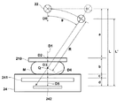
図1は、本発明による放射線断層画像取得装置の概略図、図2は放射線断層画像取得装置を構成する乳房画像撮影装置のアーム部分の正面図である。 FIG. 1 is a schematic view of a radiation tomographic image acquisition apparatus according to the present invention, and FIG. 2 is a front view of an arm portion of a breast imaging apparatus constituting the radiation tomographic image acquisition apparatus.
放射線断層画像取得装置1は、被写体の乳房Mを異なる方向から放射線を照射して撮影した複数の放射線画像を取得する乳房画像撮影装置2と、乳房画像撮影装置2で取得した複数の放射線画像を再構成して断層画像を生成する断層画像生成装置3と、乳房画像撮影装置2と断層画像生成装置3を接続するネットワーク4から構成される。
The radiation tomographic
乳房画像撮影装置2は、内部に放射線照射部(以下、放射線源という)22を収納する放射線収納部23と、内部にフラットパネルディテクター等の放射線画像検出器241をカセッテなど記録媒体保持部に収容した撮影台24と、放射線収納部23と撮影台24とが対向するように連結するアーム25と、アーム25を軸Cで取り付ける基台26と、放射線源22からの放射線の照射を制御する放射線源制御部27と、断層画像生成装置3にネットワーク4を介して撮影した放射線画像などのデータの送信を行う送信部261とから構成される。
The
基台26には、さらに、オペレータがアーム25の高さや回転量や方向を調整するための操作部28と、操作部28からの入力に従ってアーム25を上下移動および回転移動させるアーム移動手段29が設けられる。
The
アーム25には、放射線収納部23と撮影台24の間に、撮影台24上に上から被写体の乳房Mを押さえつけて圧迫する圧迫板210を取り付けるための取付部251と、取付部251をアーム25の縦方向に上下動する圧迫板移動手段252が設けられる。
The
圧迫板210にはアーム25の取付部251に差し込むための差込部211が設けられる。
The
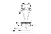
放射線収納部23には、内部に放射線源22が収納され、放射線源移動手段221でアーム移動手段29を制御して、図2に示すようにC軸を中心に放射線収納部23を回転させ、照射線源22を撮影台24の被写体の胸壁Hに向かう辺(通常は、矩形の撮影台24の長辺)に沿った方向に円弧状に放射線源22を移動させる(図3参照)。
In the
放射線源22は、円弧状に移動しながらS1、S2、・・・、SNの各照射位置から撮影台24上に載せられた乳房Mに対して異なる照射方向から放射線を照射する。また、乳房Mの撮影を行う際には、撮影台24上に乳房Mを置いて上から圧迫板210で圧迫した状態で撮影を行うため乳房Mの厚さは4cm〜5cm位になる。そこで、乳房Mを観察するのに適した画像を取得するためには、照射線源2が、撮影台24の撮影面の中心付近(具体的には、撮影台24の上面に乳房Mを置いたときに乳房Mの中心となる位置)より2cm程度上がった点Q(以下、照射ポイントという)に向けて各位置から放射線を照射するのか好ましい。
The
撮影台24の内部には、図2に示すように、放射線の照射を受けて乳房Mを透過した線量に応じた放射線画像を記録し、記録した放射線画像を出力するフラットパネルディテクター241と、フラットパネルディテクター241の下に放射線収納部23から照射された放射線が乳房Mを透過した線量を検出する線量検出器242とが配置されている。
As shown in FIG. 2, a
また、アーム25の回転中心がフラットパネルディテクター241の中心となるようにフラットパネルディテクター241の中心位置に回転の中心となる軸Cを取り付けて、アーム25を基台26に取り付ける(図2参照)。
Further, the axis C as the center of rotation is attached to the center position of the
以下、本実施の形態では、放射線画像検出器241がフラットパネルディテクターである場合の撮影台24の構成について、図4から図7を用いて説明する。
Hereinafter, in the present embodiment, the configuration of the imaging stand 24 when the
撮影台24の内部には、図4に示すように、放射線画像検出器241に記録された画像情報の読取時に使用される読取用露光光源部243と、読取用露光光源部243を副走査方向に移動させる読取用露光光源部移動手段244と、読取用露光光源部243による放射線画像検出器241への走査露光時に放射線画像検出器241から流れ出す電流を検出して画像信号を得る電流検出手段245と、放射線画像検出器241に所定の電圧を印加する高電圧電源部246と、撮影開始前に放射線画像検出器241に前露光光を照射する前露光光源部260と、放射線画像検出器241を撮影台24内部において被写体の胸壁Hに近接させる方向および胸壁Hから離間させる方向(上述の副走査方向)に移動させる放射線画像検出器移動手段247と、読取用露光光源部243、電流検出手段245、高電圧電源部246、前露光光源部260、移動手段247および244を制御する制御手段248とが配置される。
As shown in FIG. 4, a reading exposure
放射線画像検出器241は、直接変換方式かつ光読出方式の固体検出器であって、画像情報を担持する記録光が照射されることによりこの画像情報を静電潜像として記録し、読取光で走査されることにより静電潜像に応じた電流を発生するものであり、具体的には図6に示すように、ガラス基板416上に形成されており、乳房Mを透過した放射線(以下、記録光という)に対して透過性を有する第一導電層411、記録光の照射を受けることにより電荷を発生して導電性を呈する記録用光導電層412、第一導電層411に帯電される潜像極性電荷に対しては略絶縁体として作用し、かつ、該潜像極性電荷と逆極性の輸送極性電荷に対しては略導電体として作用する電荷輸送層413、読取光の照射を受けることにより電荷を発生して導電性を呈する読取用光導電層414、読取光に対して透過性を有する第二導電層415をこの順に積層してなるものである。記録用光導電層412と電荷輸送層413との界面に蓄電部417が形成される。
The
第一導電層411および第二導電層415はそれぞれ電極をなすものであり、第一導電層411の電極は2次元状に平坦な平板電極とされ、第二導電層415の電極は図中斜線で示すように、記録されている画像情報を画像信号として検出するための多数のエレメント(線状電極)415aが画素ピッチでストライプ状に配されたストライプ電極とされている(例えば特開2000−105297記載の静電記録体を参照)。エレメント415aの配列方向が主走査方向、エレメント415aの長手方向が副走査方向に対応する。
The first
この固体検出器241のサイズは大きいサイズの乳房Mに対応できるように長辺30cm×短辺24cmのものを用い、長辺方向が主走査方向、短辺方向が副走査方向となるように撮影台24内に収容される。
The solid-
読取用露光光源部243としては、LEDチップが一列に複数並べられて構成されたライン光源と、該光源から出力された光を固体検出器241上で線状に照射させる光学系とからなるものを用いる。なお、光源部243を固体検出器241と必要な距離を保ったままリニアモータからなる移動手段244により、固体検出器241のストライプ電極415a長手方向、即ち副走査方向に走査することにより固体検出器241の全面の露光を行う。なお、読取用露光光源部243および移動手段244により読取光走査手段が構成される。
The reading exposure
図7は固体検出器241および電流検出手段245の接続態様の詳細を示した図である。図示するように、被検者の胸壁Hに接する辺において、固体検出器241の各エレメント415aがTAB( Tape Automated Bonding )フィルム上に形成されたプリントパターン(不図示)を介してチャージアンプIC233と接続され、さらにチャージアンプIC233がTABフィルム232上に形成されたプリントパターン(不図示)を介してプリント基板231と接続されている。なお、本実施の形態では全てのエレメント215aを1つのチャージアンプIC233に接続するのではなく、全体として数個〜数10個のチャージアンプIC233を設け、順次隣接する数本〜百本程度のエレメント415a毎に各チャージアンプIC233に接続するようにしている。
FIG. 7 is a diagram showing details of the connection mode of the
なお、電流検出手段245は、上述の態様に限定されるものではなく、チャージアンプIC233をTABフィルム上に形成せずに、ガラス基板416上に形成する、いわゆるCOG( Chip On Glass )と呼ばれる態様としてもよい。
Note that the
図8は撮影台24内に設けられた電流検出手段245および高電圧電源部710の詳細、並びにこれらと固体検出器241との接続態様を示したブロック図である。
FIG. 8 is a block diagram showing the details of the current detection means 245 and the high voltage
高電圧電源部710は、高電圧電源711とバイアス切換手段712とが一体化された回路であり、高電圧電源711は、一旦、静電記録部241へのバイアス印加/短絡など切換えのためバイアス切換手段712を介して静電記録部241に接続されている。なお、この回路は、切換え時に流れる電流の尖頭値を制限して装置の電流が集中する箇所の破壊を防ぐために、充放電過大電流を防止するように設計されている。
The high voltage
TABフィルム上に設けられたチャージアンプIC233は、固体検出器241の各エレメント415a毎に接続された多数のチャージアンプ233aおよびサンプルホールド(S/H)233b、各サンプルホールド233bからの信号をマルチプレクスするマルチプレクサ233cを備えている。固体検出器241から流れ出す電流は各チャージアンプ233aにより電圧に変換され、該電圧がサンプルホールド233bにより所定のタイミングでサンプルホールドされ、サンプルホールドされた各エレメント415aに対応する電圧がエレメント415aの配列順に切り替わるようにマルチプレクサ233cから順次出力される(主走査の一部に相当する)。マルチプレクサ233cから順次出力された信号はプリント基板231上に設けられたマルチプレクサ231cに入力され、さらに各エレメント415aに対応する電圧がエレメント415aの配列順に切り替わるようにマルチプレクサ231cから順次出力され主走査が完了する。マルチプレクサ231cから順次出力された信号はA/D変換部231aによりデジタル信号に変換され、デジタル信号がメモリ231bに格納される。
The
前露光光源部260としては、短時間で発光/消光し、残光の非常に小さい光源が必要となるため、本実施の形態においては外部電極型希ガス蛍光ランプを利用する。詳細には前露光光源部260は、図5に示すように、図中紙面奥方向に延びる複数の外部電極型希ガス蛍光ランプ261と、該蛍光ランプ261と固体検出器241との間に挿入された波長選択フィルタ262と、蛍光ランプ261の後方に配され、蛍光ランプ261から出力された光を効率よく固体検出器241側へ反射するための反射板263とを備える。なお、前露光光は固体検出器241の第二導電層415全体に照射すればよく特に集光手段は必要ないが、照度分布は小さい方がよい。なお、光源としては蛍光ランプの代わりに、例えばLEDチップを面的に並べたものを利用するもことできる。
As the pre-exposure
移動手段247は、図示しないリニアモータなどにより構成され、固体検出器241を撮影位置と読取位置との間で平行往復移動させる。
The moving means 247 is configured by a linear motor or the like (not shown), and reciprocates the
フラットパネルディテクターは、上述で説明したような固体検出器以外にも、固体検出素子の蓄電部に蓄積された信号電荷を、該蓄電部と接続されたTFTを走査駆動して読み出すTFT読出方式を用いることができる(例えば、特開2004-80749公報、特開2004-73256公報などを参照)。 In addition to the solid state detector described above, the flat panel detector has a TFT readout system that reads out the signal charge accumulated in the power storage unit of the solid state detection element by scanning the TFT connected to the power storage unit. It can be used (for example, see JP 2004-80749 A, JP 2004-73256 A, etc.).
線量検出器(線量検出手段)242は、フラットパネルディテクター241の下部に設置され、放射線照射部が照射した放射線がフラットパネルディテクター241に入射する入射量を検出する。線量検出器242として、例えば放射線の線量を計測するセンサーとして半導体検出器が配列されたAECセンサーが用いられる。あるいは、フラットパネルディテクター241に照射された放射線の線量から検出するようにしてもよい。以下、本実施の形態では、線量検出器242をAECセンサーとして説明する。
The dose detector (dose detection means) 242 is installed in the lower part of the
放射線源制御手段27は、乳房の厚さを検出する厚さ検出手段271と、放射線源22の管電圧や管電流などを制御してする放射線照射量制御手段272とを備える。
The radiation
厚さ検出手段271は、圧迫板移動手段252で圧迫板210を移動させて乳房Mを圧迫したときの位置から乳房の厚さを求める。あるいは、操作パネルなどからオペレータが計測した乳房Mの厚さを入力したものを厚さ検出手段271で受取って用いてもよい。
The
放射線照射量制御手段272は、放射線源22の管電圧や管電流などを制御して照射される放射線量を制御するが、放射線源22の照射方向と被写体の厚さとに応じて、フラットパネルディテクター241に入射する放射線量が一定になるように放射線量を制御する。
The radiation dose control means 272 controls the radiation dose by controlling the tube voltage and tube current of the
そこで、まず、放射線源22を基準位置に移動させて基準方向から照射を行い、AECセンサー242で検出した放射線量から、放射線源22から照射された放射線が被写体を透過することにより減衰する基準減衰量を求める。
Therefore, first, the
放射線源22は、円弧状に移動しながらS1、S2、・・・、SNの各照射位置から撮影台24上に載せられた乳房Mに対して異なる照射方向から放射線を照射するが、放射線源22が被写体に放射線を照射する方向が撮影台24の上面(あるいは、フラットパネルディテクター241の検出面)の法線方向より大きく傾きほど、放射線が被写体を透過する距離が大きくなり放射線の減衰量は大きくなる。そこで、放射線源22が被写体に放射線を照射する方向が撮影台24の上面の法線方向より大きく傾きほど、照射する放射線量を大きくする。
The
ここで、放射線の減衰と放射線源からの照射方向の関係について検討する。 Here, the relationship between the attenuation of radiation and the irradiation direction from the radiation source is examined.
まず、放射線源22を撮影台24の上面と平行に移動させながら撮影する場合について検討する。図9に示すように、放射線源22から圧迫板210までの距離をa、乳房Mの厚さをb、撮影台24の上面からフラットパネルディテクター241までの距離をc、フラットパネルディテクター241からAECセンサー242までの距離をdとし、放射線源22が照射した放射線量をD0とする。
First, a case where imaging is performed while moving the
このとき、射線源22が放撮影台24の上面の法線方向よりθ傾いた方向から放射線を照射すると、圧迫板210の上面に到達する放射線D1は下式(1)のようになる。
At this time, when the
D1=α×D0/a(θ)2 (1)
ここで、a(θ)=a/cosθ
α : 距離減衰係数
さらに、放射線D1が圧迫板210を透過して乳房Mの表面に到達する放射線D2は下式(2)のようになる。
D1 = α × D0 / a (θ) 2 (1)
Where a (θ) = a / cos θ
α: Distance attenuation coefficient Further, the radiation D2 through which the radiation D1 passes through the
D2=β(θ)×D1 (2)
ここで、β(θ) : 圧迫板の透過率
放射線D2が乳房Mを透過して撮影台24の上面に到達する放射線D3は下式(3)のようになる。

Here, β (θ): transmittance of the compression plate The radiation D3 that the radiation D2 passes through the breast M and reaches the upper surface of the imaging table 24 is expressed by the following equation (3).
放射線D3が撮影台24を透過してフラットパネルディテクター241の上面に到達した放射線D4は下式(4)のようになる。
放射線D4がフラットパネルディテクター241を透過してAECセンサー242に到達した放射線D5は下式(5)のようになる。
図3に示すように、放射線源22を照射ポイントQを中心にした円弧上を移動させる場合に、AECセンサー242に到達する放射線D5’は、放射線源22とフラットパネルディテクター241との距離L’を用いて以下のように修正される。図9に示すように、照射ポイントQを中心にした円弧上を移動する放射線源22から照射ポイントQまでの距離をRとすると、放射線源22とAECセンサー242との距離L’は下式(6)のように表される。
As shown in FIG. 3, when the
L’=L(θ)+R(1−1/cosθ) (6)
したがって、放射線源22は照射ポイントQを中心にした円弧上を移動させる場合にAECセンサー242に到達する放射線D5’は下式(7)のようになる。
Therefore, when the
上述のα、β(θ)、γ(θ)、ω(θ)は、それぞれ装置によって決まる既知の値である。また、D0は放射線源22が照射した放射線量であり、D5’はAECセンサー242で検出された放射線量である。そこで、放射線源22が基準位置にあるときに基準方向から照射した放射線量D0と、AECセンサー242で検出された放射線量D5’と、α、β(θ)、γ(θ)、ω(θ)の値を式(7)に代入することにより係数λを求めることができる。例えば、撮影台24上の乳房Mの略中心を通り撮影台24の上面の法線方向に伸びた線上の放射線源22の位置を基準位置(つまり、θ=0を基準方向)とすると、式(7)は下式(8)のようになる。
式(8)に、θ=0のときに放射線源22から照射した放射線量と、AECセンサー242で検出された放射線量と、α、β(0)、γ(0)、ω(0)の値を代入して係数λを求める。
In equation (8), the radiation dose emitted from the
放射線照射量制御手段272は、フラットパネルディテクター241の上面に到達した放射線D4が一定になるように、放射線源22から照射する放射線量D0を各照射位置S1、S2、・・・、SNかで調整するのが好ましい。放射線源22は照射ポイントQを中心にした円弧上を移動させる場合には、フラットパネルディテクター241の上面に到達する放射線D4’は、下式(9)のようになる。
そこで、放射線照射量制御手段272で(9)式のD4’が一定となるように放射線源22から放射線を照射するように管電圧や管電流などを制御する。また、放射線源22を撮影台24の上面と平行に移動させる場合には、(4)式のD4が一定となるように放射線源22の管電圧や管電流などを制御する。
Therefore, the radiation voltage control means 272 controls the tube voltage, the tube current, etc. so as to irradiate the radiation from the
(9)式は、θが大きく傾いてb(θ)が大きくなるほど(つまり、放射線が前記被写体を透過する距離が大きくなるほど)、図10に示すように、フラットパネルディテクター241の上面に到達する放射線量は減衰する。従って、θが大きく傾いて放射線が乳房Mを透過する距離が大きくなるほど、放射線源22から照射する放射線量を大きくする。
Equation (9) reaches the upper surface of the
図11は本実施の形態の断層画像生成装置3の概略図である。
FIG. 11 is a schematic diagram of the tomographic
断層画像生成装置3は、乳房画像撮影装置2で撮影した放射線画像Iを受信する受信手段31と、放射線画像Iを記憶する放射線画像記憶手段32と、複数の放射線画像Iから断層画像Tを再構成する断層画像再構成手段34と、断層画像Tを表示する表示部35とを備える。
The tomographic
放射線画像記憶手段32は、ハードディスクなどの大容量記憶装置である。放射線画像記憶手段32には、乳房画像撮影装置2で放射線源22を各照射位置S1、S2、S3、・・・、Snに移動させながら撮影した放射線画像Iが複数記憶される。
The radiation image storage means 32 is a mass storage device such as a hard disk. The radiographic image storage means 32 stores a plurality of radiographic images I captured while moving the
断層画像再構成手段34は、S1、S2、S3、・・・、Snの照射位置で撮影された複数の放射線画像Iから断層画像を生成する。図12に示すように、放射線源をS1、S2、S3、・・・、Snの各位置に移動しながら異なる照射方向から乳房Mに放射線を照射すると、それぞれ放射線画像I1、I2、I3、・・・、Inが得られるものとする。そこで、例えば、放射線源の位置S1から、異なる深さに存在する対象物(O1、O 2)を投影すると、放射線画像I1上にはP11、P12の位置に投影され、放射線源の位置S2から、対象物(O1、O2)を投影すると、放射線画像I2上にはP21、P22の位置に投影される。このように、放射線源22を移動させながら異なる照射位置S1、S2、S3、・・・、Snから照射を行なうと、各放射線源22の位置に対応して対象物O1は、P11、P21、P31、・・・、Pn1の位置に投影され、対象物O2は、P12、P22、P31、・・・、Pn2の位置に投影される。
The tomographic image reconstruction means 34 generates a tomographic image from a plurality of radiation images I photographed at the irradiation positions S1, S2, S3,. As shown in FIG. 12, when the radiation is irradiated to the breast M from different irradiation directions while moving the radiation source to the respective positions S1, S2, S3,..., Sn, radiation images I1, I2, I3,.・ ・ In is assumed to be obtained. Therefore, for example, when an object (O1, O2) existing at different depths is projected from the radiation source position S1, it is projected onto the radiation image I1 at positions P11, P12, and from the radiation source position S2. When the object (O1, O2) is projected, it is projected onto the radiation image I2 at positions P21 and P22. Thus, if irradiation is performed from different irradiation positions S1, S2, S3,..., Sn while moving the
対象物O1の存在する断面を強調したい場合には、放射線画像I2を(P21−P11)分移動させ、放射線画像I3を(P31−P11)分移動させ、・・・、放射線画像Inを(Pn1−P11)分移動させた放射線画像を加算することにより、対象物O1の深さにある断面上の構造物を強調した断層画像が生成される。また、対象物O2の存在する断面を強調したい場合には、放射線画像I2は(P22−P12)分移動させ、放射線画像I3を(P32−P12)分移動させ、・・・、放射線画像Inを(Pn2−P12)分移動させて加算する。このようにして、スライス位置に応じて各放射線画像I1、I2、I3、・・・、Inを位置合わせして加算することにより、各深さの検出面に平行な断層画像を再構成する。 When it is desired to emphasize the cross section where the object O1 exists, the radiation image I2 is moved by (P21-P11), the radiation image I3 is moved by (P31-P11), and the radiation image In is (Pn1). -P11) A tomographic image in which the structure on the cross section at the depth of the target object O1 is emphasized is generated by adding the radiographic images moved by the amount. When it is desired to emphasize the cross section where the object O2 exists, the radiation image I2 is moved by (P22-P12), the radiation image I3 is moved by (P32-P12), and the radiation image In is moved. Move by (Pn2-P12) and add. In this way, the radiographic images I1, I2, I3,..., In are aligned and added in accordance with the slice position, thereby reconstructing a tomographic image parallel to the detection surface at each depth.
また、放射線源22が各位置S1、S2、S3、・・・、Snから放射線を照射する照射方向に応じて、各深さに存在する対象物が放射線画像I上に投影される位置が異なる。そこで、断層画像再構成手段34では、照射方向に応じた放射線画像I1、I2、・・・、Inの移動量を算出して、断層画像の再構成を行う。
Further, the position at which the object existing at each depth is projected on the radiation image I differs depending on the irradiation direction in which the
ここで、本実施の形態の断層画像取得装置を用いて、被写体の乳房を撮影して断層画像を生成する流れについて具体的に説明する。 Here, the flow of generating a tomographic image by photographing a breast of a subject using the tomographic image acquisition apparatus of the present embodiment will be specifically described.
まず、乳房Mの撮影を行うために、被写体が乳房画像撮像装置2の横に立つと、オペレータは、操作パネルなどの操作部28から被写体の身長に応じたアームの高さと、乳房Mの大きさや形状に応じたアームの回転角を入力し、入力された高さと回転角に応じてアーム移動手段29でアーム25の高さと角度を調整する。MLO撮影の場合は、撮影台24が被写体の胸筋に平行になるように、撮影台24を水平方向から45°〜80°の範囲で傾ける(図13参照)。通常は、60°程度傾けて撮影する。CC撮影の場合には、撮影台24を水平方向に保ち、高さを調整する。
First, in order to photograph the breast M, when the subject stands beside the breast
また、照射方向がθ=0°のときに放射線源22から照射した放射線が乳房Mの中心部分を通るように乳房Mを撮影台24の撮影面上に置く。つまり、図13に示すように、乳房Mの中心部分を通り、撮影台24内の放射線検出器241の検出面から法線方向に伸びたところに放射線源22が位置するように乳房Mが置かれる。
Further, the breast M is placed on the imaging surface of the imaging table 24 so that the radiation irradiated from the
乳房Mは立体的で厚みがあるため、そのまま撮影をすると乳腺や脂肪、血管などが障害になり腫瘍が写しだされないことがあるため、マンモグラフィの検査をする際には、圧迫板210で乳房Mをはさんで薄く均等に引き伸ばして、少ない放射線で小さなしこりの影まではっきり写しだすようにする。そこで、撮影台24が撮影に最適な高さと傾きに調整されると、乳房Mを圧迫板210で圧迫する。
Since the breast M is three-dimensional and thick, if the image is taken as it is, the mammary gland, fat, blood vessels, etc. may be obstructed and the tumor may not be copied. Therefore, when performing mammography examination, the breast M is used with the
オペレータは乳房Mの圧迫状態を確認しながら、操作パネルやフットスイッチなどの操作部28を用いて徐々に乳房Mを加圧するような指示を入力すると、入力に従って圧迫板移動手段252でアーム25の縦方向に徐々に圧迫板210を押し下げて行く。例えば、圧迫力はフットスイッチを1回押すごとに1kg単位で加圧されるようにして、乳房Mが撮影に適した厚さになるようにフットスイッチを押していく。あるいは、圧迫板が下がって乳房Mに触れると徐々に加圧されるようにしてもよい。
When the operator inputs an instruction to gradually pressurize the breast M using the
圧迫が完了すると、放射線収納部23の放射線源22から放射線を照射して乳房Mの撮影を開始する。
When the compression is completed, imaging of the breast M is started by irradiating radiation from the
標準的な乳房Mでは、例えば、図14に示すように、照射の範囲を乳房Mの中心から法線方向に伸びた線を挟んで±15°の範囲とし、3°間隔で放射線画像を11枚撮影する。各位置で照射する線量は、通常撮影のマンモグラフィを撮影するときの線量と、トモシンセシス撮影のトータルの線量が一致するように1回あたりのおおよその線量D0を決める。 In the standard breast M, for example, as shown in FIG. 14, the radiation range is set to a range of ± 15 ° across a line extending in the normal direction from the center of the breast M, and radiographic images are taken at intervals of 3 °. Take a picture. The dose to be irradiated at each position is determined to be an approximate dose D0 per time so that the dose when taking a normal mammography and the total dose of tomosynthesis imaging coincide.
まず、照射方向がθ=0°の位置で放射線源22から線量D0で照射を行い、AECセンサー241で検出された放射量D5と放射線源22から照射した線量D0とを用いて、式(8)から係数λを求める。
First, irradiation is performed with a dose D0 from the
放射線源移動手段221で放射線源22を各照射位置S1、S2、・・・、Snに順番に移動させるが、放射線照射量制御手段272は、フラットパネルディテクター241の上面に到達する放射線量(D4’)が一定となるように、各照射位置S1、S2、・・・、Snで放射線源22から照射する放射線を制御する。このようにして各照射位置から乳房Mの照射ポイントQに向けて放射線を照射して放射線画像I1、I2、I3、・・・、Inを取得する。
The
取得された放射線画像I1、I2、I3、・・・、Inを、送信部261からを断層画像生成装置3に送信する。さらに、各放射線画像I1、I2、I3、・・・、Inを撮影した照射位置S1、S2、・・・、SNなどの撮影条件も断層画像生成装置3に送信する。
The acquired radiation images I1, I2, I3,..., In are transmitted from the
断層画像生成装置3は、受信手段31で乳房画像撮像装置2から送信された放射線画像I1、I2、I3、・・・、Inを放射線画像記憶手段32に記憶する。
The tomographic
再構成手段34は、撮影条件記憶手段33に記憶されている各放射線画像I1、I2、I3、・・・、Inを撮影した照射位置S1、S2、・・・、Snに応じて、各深さにおける断層位置の断層画像を放射線画像記憶手段32に放射線画像I1、I2、I3、・・・、Inから再構成する。表示部35は、再構成された断層画像を表示する。
The reconstruction means 34 has each depth according to the irradiation positions S1, S2,..., Sn where the radiographic images I1, I2, I3,. Then, the tomographic image of the tomographic position is reconstructed from the radiation images I1, I2, I3,. The
以上詳細に説明したように、各照射位置でフラットパネルディテクターなどの画像検出器に到達する放射線量が一定になるようにして撮影された画像の濃度を一定にすることで、断層画像の精度を向上させることが可能になる。 As explained in detail above, the accuracy of tomographic images can be improved by making the density of the image taken so that the radiation amount reaching the image detector such as a flat panel detector is constant at each irradiation position. It becomes possible to improve.
上述の実施の形態では、放射線源が円弧状に移動させながらトモシンセシス撮影を行う場合について説明を行ったが、撮影台の上面と平行に放射線源を移動させるようにしてもよい。撮影台の上面と平行に放射線源を移動させるようにする場合には、フラットパネルディテクターに到達する放射線量は(4)式であらわされ、D4の値が一定となるように放射線源から照射する量を制御する。 In the above-described embodiment, the case where tomosynthesis imaging is performed while the radiation source is moved in an arc shape has been described. However, the radiation source may be moved in parallel with the upper surface of the imaging table. When the radiation source is moved in parallel with the upper surface of the imaging table, the radiation dose reaching the flat panel detector is expressed by equation (4), and irradiation is performed from the radiation source so that the value of D4 is constant. Control the amount.
上述の実施の形態では、乳房を撮影する場合について説明したが、被写体の他の部位を撮影するものであってもよい。 In the above-described embodiment, the case of photographing the breast has been described. However, another part of the subject may be photographed.
1 放射線断層画像取得装置
2 乳房画像撮影装置
3 断層画像生成装置
4 ネットワーク
22 放射線照射部
23 放射線収納部
24 撮影台
25 アーム
26 基台
27 放射線源制御部
28 操作部
29 アーム移動手段
31 受信手段
32 放射線画像記憶手段
33 撮影条件記憶手段
34 再構成手段
35 表示部
210 圧迫板
241 放射線画像検出器
251 取付部
252 圧迫板移動手段
210 圧迫板
211 差込部
221 放射線源移動手段
261 送信部
271 厚さ検出手段
272 放射線照射量制御手段
DESCRIPTION OF
Claims (1)
前記放射線画像検出器に対向して設けられ、移動しながら複数の照射方向から前記放射線画像検出器上の被写体に対して放射線を照射する放射線照射部と、
前記放射線照射部が照射した放射線が前記被写体を透過した放射線量を検出する線量検出手段と、
前記被写体の厚さを検出する厚さ検出手段と、
前記各照射方向と前記厚さに応じて、前記放射線画像検出器に入射する放射線量が一定になるように前記各照射方向から照射する放射線量を制御する放射線照射量制御手段とを備え、
前記放射線照射量制御手段が、前記放射線照射部が基準方向において照射した放射線量と、前記基準方向において前記放射線照射部が放射線を照射したときに前記線量検出手段により検出された放射線量と、前記基準方向と前記各照射方向とのなす角とに基づいて、前記各照射方向から照射する放射線量を制御するものであることを特徴とする放射線断層画像取得装置。 A radiological image detector for detecting a radiographic image of the subject;
A radiation irradiating unit that is provided facing the radiation image detector and irradiates a subject on the radiation image detector from a plurality of irradiation directions while moving;
Dose detection means for detecting the radiation dose transmitted by the radiation irradiator through the subject; and
A thickness detecting means for detecting the thickness of the subject;
Radiation dose control means for controlling the radiation dose irradiated from each irradiation direction so that the radiation dose incident on the radiation image detector is constant according to each irradiation direction and the thickness,
The radiation dose control means includes a radiation dose irradiated by the radiation irradiation section in a reference direction, a radiation dose detected by the dose detection means when the radiation irradiation section irradiates radiation in the reference direction, A radiation tomographic image acquisition apparatus for controlling a radiation dose irradiated from each irradiation direction based on a reference direction and an angle formed by each irradiation direction .
Priority Applications (2)
| Application Number | Priority Date | Filing Date | Title |
|---|---|---|---|
| JP2007099382A JP5019930B2 (en) | 2007-04-05 | 2007-04-05 | Radiation tomographic image acquisition device |
| US12/098,767 US20080247509A1 (en) | 2007-04-05 | 2008-04-07 | Radiation image obtaining system |
Applications Claiming Priority (1)
| Application Number | Priority Date | Filing Date | Title |
|---|---|---|---|
| JP2007099382A JP5019930B2 (en) | 2007-04-05 | 2007-04-05 | Radiation tomographic image acquisition device |
Related Child Applications (1)
| Application Number | Title | Priority Date | Filing Date |
|---|---|---|---|
| JP2012132579A Division JP5232320B2 (en) | 2012-06-12 | 2012-06-12 | Radiation tomographic image acquisition device |
Publications (3)
| Publication Number | Publication Date |
|---|---|
| JP2008253555A JP2008253555A (en) | 2008-10-23 |
| JP2008253555A5 JP2008253555A5 (en) | 2010-04-08 |
| JP5019930B2 true JP5019930B2 (en) | 2012-09-05 |
Family
ID=39826887
Family Applications (1)
| Application Number | Title | Priority Date | Filing Date |
|---|---|---|---|
| JP2007099382A Active JP5019930B2 (en) | 2007-04-05 | 2007-04-05 | Radiation tomographic image acquisition device |
Country Status (2)
| Country | Link |
|---|---|
| US (1) | US20080247509A1 (en) |
| JP (1) | JP5019930B2 (en) |
Families Citing this family (19)
| Publication number | Priority date | Publication date | Assignee | Title |
|---|---|---|---|---|
| JP5568232B2 (en) * | 2008-11-17 | 2014-08-06 | 富士フイルム株式会社 | Tomographic imaging system |
| JP2010233875A (en) * | 2009-03-31 | 2010-10-21 | Fujifilm Corp | Radiographic image capturing apparatus, biopsy apparatus, radiographic image capturing method, and biopsy method |
| JP5355271B2 (en) | 2009-07-24 | 2013-11-27 | 富士フイルム株式会社 | Radiation imaging equipment |
| JP5572040B2 (en) * | 2009-09-28 | 2014-08-13 | 富士フイルム株式会社 | Radiography equipment |
| JP5540865B2 (en) * | 2010-04-23 | 2014-07-02 | 株式会社島津製作所 | Radiography equipment |
| FR2967887B1 (en) * | 2010-11-26 | 2018-01-19 | General Electric Company | COMPACT MAMMOGRAPH, AND ASSOCIATED MAMMOGRAPHING METHOD |
| FR2969919B1 (en) * | 2011-01-03 | 2013-01-11 | Gen Electric | METHOD FOR ASSISTING THE POSITIONING OF AN ORGAN ON A MEDIUM OF A SYSTEM FOR ACQUIRING MEDICAL IMAGES |
| WO2012120886A1 (en) * | 2011-03-10 | 2012-09-13 | 富士フイルム株式会社 | Three-dimensional radiographic apparatus and method |
| JP5743731B2 (en) * | 2011-06-15 | 2015-07-01 | 富士フイルム株式会社 | Radiation imaging apparatus and method |
| EP2727534A4 (en) * | 2011-07-01 | 2015-04-29 | Rayence Co Ltd | Mammography detector having multiple sensors, and mammography device capable of 3d image acquisition |
| US9129389B2 (en) * | 2011-09-27 | 2015-09-08 | Hitachi Medical Corporation | X-ray CT apparatus and image correction method |
| JP5587926B2 (en) | 2012-02-10 | 2014-09-10 | 富士フイルム株式会社 | Radiation imaging system and control method thereof |
| KR102023511B1 (en) * | 2012-09-07 | 2019-09-30 | 삼성전자주식회사 | Method and apparatus for generating of X-ray mamogram |
| JP5519753B2 (en) | 2012-09-28 | 2014-06-11 | 富士フイルム株式会社 | Tomographic image generating apparatus and method |
| JP5528518B2 (en) * | 2012-09-28 | 2014-06-25 | 富士フイルム株式会社 | Radiation image generating apparatus and method |
| US9226720B2 (en) | 2012-11-16 | 2016-01-05 | Shimadzu Corporation | Radiographic apparatus |
| JP6141995B2 (en) * | 2013-09-27 | 2017-06-07 | 富士フイルム株式会社 | Mammography apparatus, radiographic imaging method and program |
| JP6050905B2 (en) * | 2015-02-25 | 2016-12-21 | 株式会社モリタ製作所 | Medical X-ray imaging apparatus and X-ray imaging method |
| US10278654B2 (en) | 2015-02-25 | 2019-05-07 | J. Morita Manufacturing Corporation | Medical X-ray photographing apparatus and X-ray photographing method |
Family Cites Families (3)
| Publication number | Priority date | Publication date | Assignee | Title |
|---|---|---|---|---|
| US5680430A (en) * | 1996-04-23 | 1997-10-21 | Continental X-Ray Corporation | Method and apparatus for controlling and optimizing output of an x-ray source |
| JP2005034436A (en) * | 2003-07-16 | 2005-02-10 | Canon Inc | Radiation image photographing apparatus |
| EP1951119A2 (en) * | 2005-11-09 | 2008-08-06 | Dexela Limited | Methods and apparatus for obtaining low-dose imaging |
-
2007
- 2007-04-05 JP JP2007099382A patent/JP5019930B2/en active Active
-
2008
- 2008-04-07 US US12/098,767 patent/US20080247509A1/en not_active Abandoned
Also Published As
| Publication number | Publication date |
|---|---|
| US20080247509A1 (en) | 2008-10-09 |
| JP2008253555A (en) | 2008-10-23 |
Similar Documents
| Publication | Publication Date | Title |
|---|---|---|
| JP5019930B2 (en) | Radiation tomographic image acquisition device | |
| JP4851296B2 (en) | Radiation tomographic image acquisition apparatus and radiation tomographic image acquisition method | |
| JP4851298B2 (en) | Radiation tomographic image generator | |
| JP4837507B2 (en) | Breast imaging device | |
| JP4597936B2 (en) | Breast imaging device | |
| US7639779B2 (en) | Apparatus for and method of capturing radiation image | |
| JP5587926B2 (en) | Radiation imaging system and control method thereof | |
| US7734013B2 (en) | Radiation image capturing apparatus and method of controlling radiation image capturing apparatus | |
| JP5670540B2 (en) | Breast radiation imaging equipment | |
| JP5032082B2 (en) | Radiation imaging apparatus and control method thereof, radiation dose detector adjustment apparatus and adjustment method thereof | |
| JP5174080B2 (en) | Breast imaging device | |
| JP5792569B2 (en) | Radiation imaging system and long imaging method of radiation imaging system | |
| JP2008264519A (en) | Radiation image capturing apparatus and method of controlling radiation image capturing apparatus | |
| JP5232320B2 (en) | Radiation tomographic image acquisition device | |
| JP2008086358A (en) | Radiographic image capturing apparatus, radiation source control device and method, and measurement position specifying device | |
| JP2008245991A (en) | Radiographic image correction device and radiographic image photographing apparatus equipped with the same | |
| JP4884271B2 (en) | Radiation imaging equipment | |
| JP2008006130A (en) | Mammography image information processing system |
Legal Events
| Date | Code | Title | Description |
|---|---|---|---|
| A521 | Request for written amendment filed |
Free format text: JAPANESE INTERMEDIATE CODE: A523 Effective date: 20100224 |
|
| A621 | Written request for application examination |
Free format text: JAPANESE INTERMEDIATE CODE: A621 Effective date: 20100224 |
|
| A131 | Notification of reasons for refusal |
Free format text: JAPANESE INTERMEDIATE CODE: A131 Effective date: 20111011 |
|
| A977 | Report on retrieval |
Free format text: JAPANESE INTERMEDIATE CODE: A971007 Effective date: 20111013 |
|
| A521 | Request for written amendment filed |
Free format text: JAPANESE INTERMEDIATE CODE: A523 Effective date: 20111115 |
|
| TRDD | Decision of grant or rejection written | ||
| A01 | Written decision to grant a patent or to grant a registration (utility model) |
Free format text: JAPANESE INTERMEDIATE CODE: A01 Effective date: 20120515 |
|
| A01 | Written decision to grant a patent or to grant a registration (utility model) |
Free format text: JAPANESE INTERMEDIATE CODE: A01 |
|
| A61 | First payment of annual fees (during grant procedure) |
Free format text: JAPANESE INTERMEDIATE CODE: A61 Effective date: 20120612 |
|
| R150 | Certificate of patent or registration of utility model |
Ref document number: 5019930 Country of ref document: JP Free format text: JAPANESE INTERMEDIATE CODE: R150 Free format text: JAPANESE INTERMEDIATE CODE: R150 |
|
| FPAY | Renewal fee payment (event date is renewal date of database) |
Free format text: PAYMENT UNTIL: 20150622 Year of fee payment: 3 |
|
| R250 | Receipt of annual fees |
Free format text: JAPANESE INTERMEDIATE CODE: R250 |
|
| R250 | Receipt of annual fees |
Free format text: JAPANESE INTERMEDIATE CODE: R250 |
|
| R250 | Receipt of annual fees |
Free format text: JAPANESE INTERMEDIATE CODE: R250 |
|
| R250 | Receipt of annual fees |
Free format text: JAPANESE INTERMEDIATE CODE: R250 |
|
| R250 | Receipt of annual fees |
Free format text: JAPANESE INTERMEDIATE CODE: R250 |
|
| R250 | Receipt of annual fees |
Free format text: JAPANESE INTERMEDIATE CODE: R250 |
|
| R250 | Receipt of annual fees |
Free format text: JAPANESE INTERMEDIATE CODE: R250 |
|
| R250 | Receipt of annual fees |
Free format text: JAPANESE INTERMEDIATE CODE: R250 |
|
| R250 | Receipt of annual fees |
Free format text: JAPANESE INTERMEDIATE CODE: R250 |
|
| R250 | Receipt of annual fees |
Free format text: JAPANESE INTERMEDIATE CODE: R250 |