JP5000656B2 - Flare deployable stent and apparatus and method for manufacturing and using the same - Google Patents
Flare deployable stent and apparatus and method for manufacturing and using the same Download PDFInfo
- Publication number
- JP5000656B2 JP5000656B2 JP2008528119A JP2008528119A JP5000656B2 JP 5000656 B2 JP5000656 B2 JP 5000656B2 JP 2008528119 A JP2008528119 A JP 2008528119A JP 2008528119 A JP2008528119 A JP 2008528119A JP 5000656 B2 JP5000656 B2 JP 5000656B2
- Authority
- JP
- Japan
- Prior art keywords
- stent
- balloon
- expanded
- band
- state
- Prior art date
- Legal status (The legal status is an assumption and is not a legal conclusion. Google has not performed a legal analysis and makes no representation as to the accuracy of the status listed.)
- Active
Links
Images


Classifications
-
- A—HUMAN NECESSITIES
- A61—MEDICAL OR VETERINARY SCIENCE; HYGIENE
- A61F—FILTERS IMPLANTABLE INTO BLOOD VESSELS; PROSTHESES; DEVICES PROVIDING PATENCY TO, OR PREVENTING COLLAPSING OF, TUBULAR STRUCTURES OF THE BODY, e.g. STENTS; ORTHOPAEDIC, NURSING OR CONTRACEPTIVE DEVICES; FOMENTATION; TREATMENT OR PROTECTION OF EYES OR EARS; BANDAGES, DRESSINGS OR ABSORBENT PADS; FIRST-AID KITS
- A61F2/00—Filters implantable into blood vessels; Prostheses, i.e. artificial substitutes or replacements for parts of the body; Appliances for connecting them with the body; Devices providing patency to, or preventing collapsing of, tubular structures of the body, e.g. stents
- A61F2/95—Instruments specially adapted for placement or removal of stents or stent-grafts
- A61F2/958—Inflatable balloons for placing stents or stent-grafts
-
- A—HUMAN NECESSITIES
- A61—MEDICAL OR VETERINARY SCIENCE; HYGIENE
- A61F—FILTERS IMPLANTABLE INTO BLOOD VESSELS; PROSTHESES; DEVICES PROVIDING PATENCY TO, OR PREVENTING COLLAPSING OF, TUBULAR STRUCTURES OF THE BODY, e.g. STENTS; ORTHOPAEDIC, NURSING OR CONTRACEPTIVE DEVICES; FOMENTATION; TREATMENT OR PROTECTION OF EYES OR EARS; BANDAGES, DRESSINGS OR ABSORBENT PADS; FIRST-AID KITS
- A61F2/00—Filters implantable into blood vessels; Prostheses, i.e. artificial substitutes or replacements for parts of the body; Appliances for connecting them with the body; Devices providing patency to, or preventing collapsing of, tubular structures of the body, e.g. stents
- A61F2/82—Devices providing patency to, or preventing collapsing of, tubular structures of the body, e.g. stents
- A61F2/86—Stents in a form characterised by the wire-like elements; Stents in the form characterised by a net-like or mesh-like structure
- A61F2/90—Stents in a form characterised by the wire-like elements; Stents in the form characterised by a net-like or mesh-like structure characterised by a net-like or mesh-like structure
- A61F2/91—Stents in a form characterised by the wire-like elements; Stents in the form characterised by a net-like or mesh-like structure characterised by a net-like or mesh-like structure made from perforated sheet material or tubes, e.g. perforated by laser cuts or etched holes
- A61F2/915—Stents in a form characterised by the wire-like elements; Stents in the form characterised by a net-like or mesh-like structure characterised by a net-like or mesh-like structure made from perforated sheet material or tubes, e.g. perforated by laser cuts or etched holes with bands having a meander structure, adjacent bands being connected to each other
-
- A—HUMAN NECESSITIES
- A61—MEDICAL OR VETERINARY SCIENCE; HYGIENE
- A61F—FILTERS IMPLANTABLE INTO BLOOD VESSELS; PROSTHESES; DEVICES PROVIDING PATENCY TO, OR PREVENTING COLLAPSING OF, TUBULAR STRUCTURES OF THE BODY, e.g. STENTS; ORTHOPAEDIC, NURSING OR CONTRACEPTIVE DEVICES; FOMENTATION; TREATMENT OR PROTECTION OF EYES OR EARS; BANDAGES, DRESSINGS OR ABSORBENT PADS; FIRST-AID KITS
- A61F2/00—Filters implantable into blood vessels; Prostheses, i.e. artificial substitutes or replacements for parts of the body; Appliances for connecting them with the body; Devices providing patency to, or preventing collapsing of, tubular structures of the body, e.g. stents
- A61F2/02—Prostheses implantable into the body
- A61F2/30—Joints
- A61F2002/30001—Additional features of subject-matter classified in A61F2/28, A61F2/30 and subgroups thereof
- A61F2002/30316—The prosthesis having different structural features at different locations within the same prosthesis; Connections between prosthetic parts; Special structural features of bone or joint prostheses not otherwise provided for
- A61F2002/30317—The prosthesis having different structural features at different locations within the same prosthesis
- A61F2002/30322—The prosthesis having different structural features at different locations within the same prosthesis differing in surface structures
-
- A—HUMAN NECESSITIES
- A61—MEDICAL OR VETERINARY SCIENCE; HYGIENE
- A61F—FILTERS IMPLANTABLE INTO BLOOD VESSELS; PROSTHESES; DEVICES PROVIDING PATENCY TO, OR PREVENTING COLLAPSING OF, TUBULAR STRUCTURES OF THE BODY, e.g. STENTS; ORTHOPAEDIC, NURSING OR CONTRACEPTIVE DEVICES; FOMENTATION; TREATMENT OR PROTECTION OF EYES OR EARS; BANDAGES, DRESSINGS OR ABSORBENT PADS; FIRST-AID KITS
- A61F2/00—Filters implantable into blood vessels; Prostheses, i.e. artificial substitutes or replacements for parts of the body; Appliances for connecting them with the body; Devices providing patency to, or preventing collapsing of, tubular structures of the body, e.g. stents
- A61F2/82—Devices providing patency to, or preventing collapsing of, tubular structures of the body, e.g. stents
- A61F2002/821—Ostial stents
-
- A—HUMAN NECESSITIES
- A61—MEDICAL OR VETERINARY SCIENCE; HYGIENE
- A61F—FILTERS IMPLANTABLE INTO BLOOD VESSELS; PROSTHESES; DEVICES PROVIDING PATENCY TO, OR PREVENTING COLLAPSING OF, TUBULAR STRUCTURES OF THE BODY, e.g. STENTS; ORTHOPAEDIC, NURSING OR CONTRACEPTIVE DEVICES; FOMENTATION; TREATMENT OR PROTECTION OF EYES OR EARS; BANDAGES, DRESSINGS OR ABSORBENT PADS; FIRST-AID KITS
- A61F2/00—Filters implantable into blood vessels; Prostheses, i.e. artificial substitutes or replacements for parts of the body; Appliances for connecting them with the body; Devices providing patency to, or preventing collapsing of, tubular structures of the body, e.g. stents
- A61F2/82—Devices providing patency to, or preventing collapsing of, tubular structures of the body, e.g. stents
- A61F2/86—Stents in a form characterised by the wire-like elements; Stents in the form characterised by a net-like or mesh-like structure
- A61F2/90—Stents in a form characterised by the wire-like elements; Stents in the form characterised by a net-like or mesh-like structure characterised by a net-like or mesh-like structure
- A61F2/91—Stents in a form characterised by the wire-like elements; Stents in the form characterised by a net-like or mesh-like structure characterised by a net-like or mesh-like structure made from perforated sheet material or tubes, e.g. perforated by laser cuts or etched holes
- A61F2/915—Stents in a form characterised by the wire-like elements; Stents in the form characterised by a net-like or mesh-like structure characterised by a net-like or mesh-like structure made from perforated sheet material or tubes, e.g. perforated by laser cuts or etched holes with bands having a meander structure, adjacent bands being connected to each other
- A61F2002/91525—Stents in a form characterised by the wire-like elements; Stents in the form characterised by a net-like or mesh-like structure characterised by a net-like or mesh-like structure made from perforated sheet material or tubes, e.g. perforated by laser cuts or etched holes with bands having a meander structure, adjacent bands being connected to each other within the whole structure different bands showing different meander characteristics, e.g. frequency or amplitude
-
- A—HUMAN NECESSITIES
- A61—MEDICAL OR VETERINARY SCIENCE; HYGIENE
- A61F—FILTERS IMPLANTABLE INTO BLOOD VESSELS; PROSTHESES; DEVICES PROVIDING PATENCY TO, OR PREVENTING COLLAPSING OF, TUBULAR STRUCTURES OF THE BODY, e.g. STENTS; ORTHOPAEDIC, NURSING OR CONTRACEPTIVE DEVICES; FOMENTATION; TREATMENT OR PROTECTION OF EYES OR EARS; BANDAGES, DRESSINGS OR ABSORBENT PADS; FIRST-AID KITS
- A61F2/00—Filters implantable into blood vessels; Prostheses, i.e. artificial substitutes or replacements for parts of the body; Appliances for connecting them with the body; Devices providing patency to, or preventing collapsing of, tubular structures of the body, e.g. stents
- A61F2/82—Devices providing patency to, or preventing collapsing of, tubular structures of the body, e.g. stents
- A61F2/86—Stents in a form characterised by the wire-like elements; Stents in the form characterised by a net-like or mesh-like structure
- A61F2/90—Stents in a form characterised by the wire-like elements; Stents in the form characterised by a net-like or mesh-like structure characterised by a net-like or mesh-like structure
- A61F2/91—Stents in a form characterised by the wire-like elements; Stents in the form characterised by a net-like or mesh-like structure characterised by a net-like or mesh-like structure made from perforated sheet material or tubes, e.g. perforated by laser cuts or etched holes
- A61F2/915—Stents in a form characterised by the wire-like elements; Stents in the form characterised by a net-like or mesh-like structure characterised by a net-like or mesh-like structure made from perforated sheet material or tubes, e.g. perforated by laser cuts or etched holes with bands having a meander structure, adjacent bands being connected to each other
- A61F2002/91533—Stents in a form characterised by the wire-like elements; Stents in the form characterised by a net-like or mesh-like structure characterised by a net-like or mesh-like structure made from perforated sheet material or tubes, e.g. perforated by laser cuts or etched holes with bands having a meander structure, adjacent bands being connected to each other characterised by the phase between adjacent bands
-
- A—HUMAN NECESSITIES
- A61—MEDICAL OR VETERINARY SCIENCE; HYGIENE
- A61F—FILTERS IMPLANTABLE INTO BLOOD VESSELS; PROSTHESES; DEVICES PROVIDING PATENCY TO, OR PREVENTING COLLAPSING OF, TUBULAR STRUCTURES OF THE BODY, e.g. STENTS; ORTHOPAEDIC, NURSING OR CONTRACEPTIVE DEVICES; FOMENTATION; TREATMENT OR PROTECTION OF EYES OR EARS; BANDAGES, DRESSINGS OR ABSORBENT PADS; FIRST-AID KITS
- A61F2/00—Filters implantable into blood vessels; Prostheses, i.e. artificial substitutes or replacements for parts of the body; Appliances for connecting them with the body; Devices providing patency to, or preventing collapsing of, tubular structures of the body, e.g. stents
- A61F2/82—Devices providing patency to, or preventing collapsing of, tubular structures of the body, e.g. stents
- A61F2/86—Stents in a form characterised by the wire-like elements; Stents in the form characterised by a net-like or mesh-like structure
- A61F2/90—Stents in a form characterised by the wire-like elements; Stents in the form characterised by a net-like or mesh-like structure characterised by a net-like or mesh-like structure
- A61F2/91—Stents in a form characterised by the wire-like elements; Stents in the form characterised by a net-like or mesh-like structure characterised by a net-like or mesh-like structure made from perforated sheet material or tubes, e.g. perforated by laser cuts or etched holes
- A61F2/915—Stents in a form characterised by the wire-like elements; Stents in the form characterised by a net-like or mesh-like structure characterised by a net-like or mesh-like structure made from perforated sheet material or tubes, e.g. perforated by laser cuts or etched holes with bands having a meander structure, adjacent bands being connected to each other
- A61F2002/9155—Adjacent bands being connected to each other
- A61F2002/91558—Adjacent bands being connected to each other connected peak to peak
-
- A—HUMAN NECESSITIES
- A61—MEDICAL OR VETERINARY SCIENCE; HYGIENE
- A61F—FILTERS IMPLANTABLE INTO BLOOD VESSELS; PROSTHESES; DEVICES PROVIDING PATENCY TO, OR PREVENTING COLLAPSING OF, TUBULAR STRUCTURES OF THE BODY, e.g. STENTS; ORTHOPAEDIC, NURSING OR CONTRACEPTIVE DEVICES; FOMENTATION; TREATMENT OR PROTECTION OF EYES OR EARS; BANDAGES, DRESSINGS OR ABSORBENT PADS; FIRST-AID KITS
- A61F2230/00—Geometry of prostheses classified in groups A61F2/00 - A61F2/26 or A61F2/82 or A61F9/00 or A61F11/00 or subgroups thereof
- A61F2230/0002—Two-dimensional shapes, e.g. cross-sections
- A61F2230/0028—Shapes in the form of latin or greek characters
- A61F2230/005—Rosette-shaped, e.g. star-shaped
-
- A—HUMAN NECESSITIES
- A61—MEDICAL OR VETERINARY SCIENCE; HYGIENE
- A61F—FILTERS IMPLANTABLE INTO BLOOD VESSELS; PROSTHESES; DEVICES PROVIDING PATENCY TO, OR PREVENTING COLLAPSING OF, TUBULAR STRUCTURES OF THE BODY, e.g. STENTS; ORTHOPAEDIC, NURSING OR CONTRACEPTIVE DEVICES; FOMENTATION; TREATMENT OR PROTECTION OF EYES OR EARS; BANDAGES, DRESSINGS OR ABSORBENT PADS; FIRST-AID KITS
- A61F2230/00—Geometry of prostheses classified in groups A61F2/00 - A61F2/26 or A61F2/82 or A61F9/00 or A61F11/00 or subgroups thereof
- A61F2230/0002—Two-dimensional shapes, e.g. cross-sections
- A61F2230/0028—Shapes in the form of latin or greek characters
- A61F2230/0054—V-shaped
-
- A—HUMAN NECESSITIES
- A61—MEDICAL OR VETERINARY SCIENCE; HYGIENE
- A61F—FILTERS IMPLANTABLE INTO BLOOD VESSELS; PROSTHESES; DEVICES PROVIDING PATENCY TO, OR PREVENTING COLLAPSING OF, TUBULAR STRUCTURES OF THE BODY, e.g. STENTS; ORTHOPAEDIC, NURSING OR CONTRACEPTIVE DEVICES; FOMENTATION; TREATMENT OR PROTECTION OF EYES OR EARS; BANDAGES, DRESSINGS OR ABSORBENT PADS; FIRST-AID KITS
- A61F2230/00—Geometry of prostheses classified in groups A61F2/00 - A61F2/26 or A61F2/82 or A61F9/00 or A61F11/00 or subgroups thereof
- A61F2230/0063—Three-dimensional shapes
- A61F2230/0067—Three-dimensional shapes conical
-
- A—HUMAN NECESSITIES
- A61—MEDICAL OR VETERINARY SCIENCE; HYGIENE
- A61F—FILTERS IMPLANTABLE INTO BLOOD VESSELS; PROSTHESES; DEVICES PROVIDING PATENCY TO, OR PREVENTING COLLAPSING OF, TUBULAR STRUCTURES OF THE BODY, e.g. STENTS; ORTHOPAEDIC, NURSING OR CONTRACEPTIVE DEVICES; FOMENTATION; TREATMENT OR PROTECTION OF EYES OR EARS; BANDAGES, DRESSINGS OR ABSORBENT PADS; FIRST-AID KITS
- A61F2250/00—Special features of prostheses classified in groups A61F2/00 - A61F2/26 or A61F2/82 or A61F9/00 or A61F11/00 or subgroups thereof
- A61F2250/0014—Special features of prostheses classified in groups A61F2/00 - A61F2/26 or A61F2/82 or A61F9/00 or A61F11/00 or subgroups thereof having different values of a given property or geometrical feature, e.g. mechanical property or material property, at different locations within the same prosthesis
- A61F2250/0018—Special features of prostheses classified in groups A61F2/00 - A61F2/26 or A61F2/82 or A61F9/00 or A61F11/00 or subgroups thereof having different values of a given property or geometrical feature, e.g. mechanical property or material property, at different locations within the same prosthesis differing in elasticity, stiffness or compressibility
-
- A—HUMAN NECESSITIES
- A61—MEDICAL OR VETERINARY SCIENCE; HYGIENE
- A61F—FILTERS IMPLANTABLE INTO BLOOD VESSELS; PROSTHESES; DEVICES PROVIDING PATENCY TO, OR PREVENTING COLLAPSING OF, TUBULAR STRUCTURES OF THE BODY, e.g. STENTS; ORTHOPAEDIC, NURSING OR CONTRACEPTIVE DEVICES; FOMENTATION; TREATMENT OR PROTECTION OF EYES OR EARS; BANDAGES, DRESSINGS OR ABSORBENT PADS; FIRST-AID KITS
- A61F2250/00—Special features of prostheses classified in groups A61F2/00 - A61F2/26 or A61F2/82 or A61F9/00 or A61F11/00 or subgroups thereof
- A61F2250/0014—Special features of prostheses classified in groups A61F2/00 - A61F2/26 or A61F2/82 or A61F9/00 or A61F11/00 or subgroups thereof having different values of a given property or geometrical feature, e.g. mechanical property or material property, at different locations within the same prosthesis
- A61F2250/0026—Special features of prostheses classified in groups A61F2/00 - A61F2/26 or A61F2/82 or A61F9/00 or A61F11/00 or subgroups thereof having different values of a given property or geometrical feature, e.g. mechanical property or material property, at different locations within the same prosthesis differing in surface structures
-
- A—HUMAN NECESSITIES
- A61—MEDICAL OR VETERINARY SCIENCE; HYGIENE
- A61F—FILTERS IMPLANTABLE INTO BLOOD VESSELS; PROSTHESES; DEVICES PROVIDING PATENCY TO, OR PREVENTING COLLAPSING OF, TUBULAR STRUCTURES OF THE BODY, e.g. STENTS; ORTHOPAEDIC, NURSING OR CONTRACEPTIVE DEVICES; FOMENTATION; TREATMENT OR PROTECTION OF EYES OR EARS; BANDAGES, DRESSINGS OR ABSORBENT PADS; FIRST-AID KITS
- A61F2250/00—Special features of prostheses classified in groups A61F2/00 - A61F2/26 or A61F2/82 or A61F9/00 or A61F11/00 or subgroups thereof
- A61F2250/0014—Special features of prostheses classified in groups A61F2/00 - A61F2/26 or A61F2/82 or A61F9/00 or A61F11/00 or subgroups thereof having different values of a given property or geometrical feature, e.g. mechanical property or material property, at different locations within the same prosthesis
- A61F2250/0039—Special features of prostheses classified in groups A61F2/00 - A61F2/26 or A61F2/82 or A61F9/00 or A61F11/00 or subgroups thereof having different values of a given property or geometrical feature, e.g. mechanical property or material property, at different locations within the same prosthesis differing in diameter
-
- A—HUMAN NECESSITIES
- A61—MEDICAL OR VETERINARY SCIENCE; HYGIENE
- A61M—DEVICES FOR INTRODUCING MEDIA INTO, OR ONTO, THE BODY; DEVICES FOR TRANSDUCING BODY MEDIA OR FOR TAKING MEDIA FROM THE BODY; DEVICES FOR PRODUCING OR ENDING SLEEP OR STUPOR
- A61M25/00—Catheters; Hollow probes
- A61M25/10—Balloon catheters
- A61M25/1002—Balloon catheters characterised by balloon shape
Landscapes
- Health & Medical Sciences (AREA)
- Engineering & Computer Science (AREA)
- Biomedical Technology (AREA)
- Heart & Thoracic Surgery (AREA)
- Cardiology (AREA)
- Oral & Maxillofacial Surgery (AREA)
- Transplantation (AREA)
- Vascular Medicine (AREA)
- Life Sciences & Earth Sciences (AREA)
- Animal Behavior & Ethology (AREA)
- General Health & Medical Sciences (AREA)
- Public Health (AREA)
- Veterinary Medicine (AREA)
- Optics & Photonics (AREA)
- Physics & Mathematics (AREA)
- Media Introduction/Drainage Providing Device (AREA)
Description
本発明は、一般に、管腔内プロテーゼまたは「ステント」に関し、とりわけ拡張ステントや、こうしたステントを血管または他の体腔の小孔に送達する装置および方法に関する。 The present invention relates generally to endoluminal prostheses or “stents”, and more particularly to expansion stents and devices and methods for delivering such stents to small holes in blood vessels or other body cavities.
狭窄部、閉塞部、および/または患者の血管または他の体腔内の他の病変部を押し広げ、または処置するための管状の管腔内プロテーゼまたは「ステント」が提案されてきた。例えば、自己拡張型ステントが、皮膜シースまたは他の拘束部品などにより収縮された状態でカテーテル内に維持され、血管または他の体腔内の狭窄部などの標的部位に送達される。一旦ステントが標的部位に配置されると、拘束部品は取り外され、ステントは自動的に拡張して、標的部位にある血管を押し広げることができる。択一的には、バルーン拡張型ステントを収縮状態でバルーンに取り付け、または固定するなどして、カテーテルに取り付けることができる。ステントを標的部位に配置した後、バルーンを膨張させて、ステントを拡張させ、血管を広げることができる。 Tubular endoluminal prostheses or “stents” have been proposed for expanding or treating stenosis, occlusions, and / or other lesions in a patient's blood vessels or other body cavities. For example, a self-expanding stent is maintained in a catheter in a contracted state, such as with a sheath sheath or other restraint, and delivered to a target site, such as a stenosis in a blood vessel or other body cavity. Once the stent is placed at the target site, the restraining component can be removed and the stent can automatically expand to expand the blood vessels at the target site. Alternatively, the balloon expandable stent can be attached to the catheter, such as attached or secured to the balloon in a deflated state. After placing the stent at the target site, the balloon can be inflated to expand the stent and dilate the blood vessel.
狭窄部または他の病変部は、小孔(小口)または分岐点、すなわち支流血管が主流血管または幹管から延びるところで形成される。例えば、こうした病変部は、大動脈起始部に直近の冠状動脈内で形成されることがある。シャクノヴィッチ(Shaknovich)に付与された米国特許第5,749,890号公報には、動脈口の病変にステントを配置するためのステント送達アセンブリが開示されている。マイラ(Myler)に付与された米国特許第5,632,762号公報には、小孔内にステントを配置するためのカテーテル上の傾斜バルーンが開示されている。ラム(Lam)に付与された米国特許第5,607,444号公報には、管状本体部と変形可能な展開部を有する拡張型小孔ステントが開示されている。ナッチギャル(Nachtigall)に付与された米国特許出願公開第2002/0077691号公報によれば、送達システムであって、送達の際には収縮状態のステントを保持するためのシースと、送達システムを所望の位置まで挿入する際には展開可能な係止部を非展開状態に保持する固定具とを有するものが開示されている。 A stenosis or other lesion is formed at a stoma (breast) or bifurcation, ie where a tributary blood vessel extends from a main blood vessel or trunk. For example, such a lesion may be formed in the coronary artery closest to the aortic root. US Pat. No. 5,749,890 issued to Shaknovich discloses a stent delivery assembly for placing a stent in an arterial lesion. U.S. Pat. No. 5,632,762 to Myler discloses a tilted balloon on a catheter for placing a stent within a stoma. U.S. Pat. No. 5,607,444 to Lam discloses an expandable stoma stent having a tubular body and a deformable deployment. According to U.S. Patent Application Publication No. 2002/0077691, granted to Nachtigall, a delivery system comprising a sheath for holding a contracted stent during delivery, a delivery system having a desired A device having a fixing member that holds a deployable locking portion in a non-deployed state when inserted to a position is disclosed.
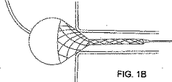
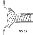
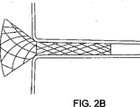
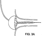
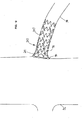
図1〜3には、異なる形状および/または大きさを有するさまざまな小孔内にフレア展開ステント(flared stent:朝顔の花が開くように展開するステント)を展開させる様子、および不適切に展開させたときのリスクについて図示されている。すなわち、フレア展開ステントならびに小孔内にフレア展開ステントを送達するための装置および方法が有用である。
本願発明は、内視鏡プロテーゼまたは「ステント」に関し、とりわけフレア展開ステント、およびこうしたステントを血管または他の体内管腔の小孔へ送達するための装置および方法に関する。 The present invention relates to endoscopic prostheses or “stents”, and more particularly to flare deployed stents and devices and methods for delivering such stents to small holes in blood vessels or other body lumens.
1つの実施形態によれば、管状部材からなるステントが提供され、この管状部材は、第1端および第2端を有し、これらの間に長手方向軸を形成し、第1端と第2端の間に配設された複数のセルを有する。一般に、ステントは、収縮状態から拡張状態に拡張したとき、外側にフレア展開するように構成された第1の端部部品と、ステントがフレア展開状態から完全拡張状態に拡張したときに拡張するように構成された、第1の部品に隣接する第2の部品とを有する。第2の部品は、複数の可撓性連結部を介して、第1の端部部品に連結してもよく、こうすることにより第1の端部部品が外側にフレア展開しやすくすることができる。 According to one embodiment, a stent comprising a tubular member is provided, the tubular member having a first end and a second end, forming a longitudinal axis therebetween, the first end and the second end. It has a plurality of cells arranged between the ends. In general, a stent is configured to expand when a stent is expanded from a flare expanded state to a fully expanded state with a first end piece configured to flare outward when expanded from a contracted state to an expanded state. And a second part adjacent to the first part. The second part may be connected to the first end part via a plurality of flexible connection parts, and this may facilitate the first end part to flare outward. it can.
別の実施形態によれば、管状部材からなるステントが提供され、この管状部材は、第1端および第2端を有し、これらの間に長手方向軸を形成し、第1端と第2端の間に配設された複数のセルを有する。管状部材は、収縮状態から中間フレア展開状態を経由して完全拡張状態またはフレア展開状態に拡張することができる。ステントが収縮状態からフレア展開状態に拡張したとき、外側にフレア展開するように構成された第1の端部部品と、第1の端部部品に隣接する第2の部品と、第2の部品を第1の端部部品に連結する複数の可撓性連結部とを有するものであってもよい。 According to another embodiment, a stent comprising a tubular member is provided, the tubular member having a first end and a second end, forming a longitudinal axis therebetween, the first end and the second end. It has a plurality of cells arranged between the ends. The tubular member can be expanded from a contracted state to a fully expanded state or a flare deployed state via an intermediate flare deployed state. A first end piece configured to flare outward when the stent is expanded from a contracted state to a flare deployed state; a second part adjacent to the first end part; and a second part And a plurality of flexible connecting parts that connect the first end part to the first end part.
例示的な実施形態では、第1の端部部品は、第1端において第1の組のセルと、第1の組のセルに隣接する第2の組のセルとを有し、第2の組のセルは、収縮した状態にあるとき実質的に軸方向に延びるストラットまたは部材を有する。連結部は、第2の組のセルを第2の部品に連結し、第2の組のセルのストラットがフレア展開状態においてほぼ半径方向外側に配向するように変形する。追加的または択一的に、第1の組のセルは、収縮した状態にあるとき実質的に軸方向に延びるストラットまたは部材を有する。第1の組のセルの軸方向部材は、完全にフレア展開した状態において、実質的に周方向に配向される。 In an exemplary embodiment, the first end piece has a first set of cells at a first end and a second set of cells adjacent to the first set of cells, The set of cells has struts or members that extend substantially axially when in the contracted state. The coupling portion couples the second set of cells to the second part and deforms so that the struts of the second set of cells are oriented substantially radially outward in the flare deployed state. Additionally or alternatively, the first set of cells has struts or members that extend substantially axially when in a contracted state. The axial members of the first set of cells are oriented substantially circumferentially in a fully flared state.
さらに別の実施形態によれば、管状部材からなるステントが提供され、この管状部材は、第1端および第2端を有し、これらの間に長手方向軸を形成し、第1端と第2端の間に配設された複数のセルを有する。一般に、ステントは、収縮状態から中間フレア展開状態に拡張したとき、外側にフレア展開するように構成された第1のフレア展開部と、ステントがフレア展開状態から完全拡張状態に拡張したときに拡張するように構成された、第1のフレア展開部に隣接する第2の本体部とを有する。第2の本体部は第1のフレア展開部に直近の近位本体部と、近位本体部と第2端の間に延びる遠位本体部とを有する。 According to yet another embodiment, a stent comprising a tubular member is provided, the tubular member having a first end and a second end, forming a longitudinal axis therebetween, the first end and the second end. It has a plurality of cells arranged between two ends. Generally, a stent expands when the stent expands from a flare deployed state to a fully expanded state, with a first flare deployed portion configured to flare outward when expanded from a contracted state to an intermediate flare deployed state. And a second main body portion adjacent to the first flare development portion. The second body portion has a proximal body portion proximate the first flare deployment portion and a distal body portion extending between the proximal body portion and the second end.
1つの実施形態において、近位本体部は、遠位本体部より大きい半径方向強度を有する。追加的または択一的には、遠位本体部は、フレア展開部より大きい半径方向強度を有する。すなわち例示的な実施形態では、フレア展開部は本体部より容易に拡張し、ステントを移植した後、小孔を押し広げた状態で維持しやすくするために、本体部の近位本体部がステントの中で最も大きい半径方向強度を有する。 In one embodiment, the proximal body portion has a greater radial strength than the distal body portion. Additionally or alternatively, the distal body portion has a greater radial strength than the flare deployment. That is, in an exemplary embodiment, the proximal body portion of the body portion expands more easily than the body portion, and the proximal body portion of the body portion is more prone to maintain the ostium in an expanded state after implantation of the stent. Has the largest radial strength.
さらに別の実施形態によれば、主流体内管腔および支流体内管腔の間で連通する小孔を処置するための装置が提供される。この装置は、概略、近位端と、主流体内管腔および支流体内管腔の内部に案内されるような大きさの遠位端とを有する延伸部材とを有する。また、この装置は、第1の収縮状態から第2のフレア展開状態および第3の拡張状態に拡張することができる遠位端に配置された拡張可能部品を有する。ステントが拡張可能部品の上方に配置され、第1の端部部品と、複数の可撓性連結部を介して第1の端部部品に連結される第2の部品とを有する。 In accordance with yet another embodiment, an apparatus is provided for treating a stoma communicating between a main fluid lumen and a branch fluid lumen. The device generally has an elongate member having a proximal end and a distal end sized to be guided within a main fluid lumen and a branch fluid lumen. The device also has an expandable component disposed at the distal end that can be expanded from a first contracted state to a second flared deployed state and a third expanded state. A stent is disposed above the expandable component and has a first end component and a second component coupled to the first end component via a plurality of flexible couplings.
ステントおよび/または拡張可能部品は、拡張可能部品が第2の状態に拡張するとき、ステントの第1の端部部品がフレア展開状態に拡張し、拡張可能部品が第3の状態に拡張するとき、第2の部品が半径方向外側に拡張し、第1の端部部品がさらに半径方向外側に拡張するように構成される。1つの実施形態では、拡張可能部品は、ステントの第1の端部部品の上方に配置された第1のバルーンと、ステントの第2の部品の少なくとも一部の上方に配置された第2のバルーンとを有する。第2のフレア展開状態が第1のバルーンの膨張により形成されるように、第1のバルーンは第2のバルーンとは独立して拡張させることができる The stent and / or expandable component is expanded when the expandable component expands to the second state, when the first end component of the stent expands to the flare deployed state and expandable component expands to the third state. The second part extends radially outwardly and the first end part further extends radially outwardly. In one embodiment, the expandable component includes a first balloon disposed over the first end component of the stent and a second balloon disposed over at least a portion of the second component of the stent. And a balloon. The first balloon can be expanded independently of the second balloon so that the second flare deployment state is formed by inflation of the first balloon.
さらに別の実施形態によれば、主流体内管腔および支流体内管腔の間で連通する小孔を処置するための装置が提供される。この装置は、概略、近位端と、主流体内管腔および支流体内管腔の少なくとも一方の内部に案内されるような大きさの遠位端とを有する伸張部材を有する。また、この装置は、遠位端において、近位バルーンおよび遠位バルーンを有する。これらのバルーンは、収縮状態から拡張状態に拡張可能であり、拡張状態においては、遠位バルーンが実質的な円筒形状を有し、近位バルーンが実質的な球形形状を有する In accordance with yet another embodiment, an apparatus is provided for treating a stoma communicating between a main fluid lumen and a branch fluid lumen. The device generally includes an extension member having a proximal end and a distal end sized to be guided within at least one of a main fluid lumen and a branch fluid lumen. The device also has a proximal balloon and a distal balloon at the distal end. These balloons are expandable from a deflated state to an expanded state, where the distal balloon has a substantially cylindrical shape and the proximal balloon has a substantially spherical shape.
これらのバルーンは、互いに独立して拡張および/または収縮させることができる。追加的または択一的に、近位バルーンは弾性または半弾性を有し、遠位バルーンは実質的に非弾性を有する。 These balloons can be expanded and / or deflated independently of each other. Additionally or alternatively, the proximal balloon has elasticity or semi-elasticity and the distal balloon has substantially inelasticity.
このステントは、遠位端にあって、少なくとも部分的には各バルーンを覆い、第1のフレア展開部と第2の本体部とを有する。随意的には、第2の本体部は、フレア展開部に隣接するより剛性の高い近位本体部と、より剛性の低い遠位本体部とを有する。1つの実施形態では、このステントは、伸張部材の遠位端にあって、第1のフレア展開部と近位本体部の少なくとも一部が近位バルーンを覆い、遠位本体部が遠位バルーンを覆う。 The stent is at the distal end and at least partially covers each balloon and has a first flared deployment and a second body. Optionally, the second body portion has a stiffer proximal body portion adjacent to the flare deployment and a less rigid distal body portion. In one embodiment, the stent is at the distal end of the extension member, wherein the first flare deployment and at least a portion of the proximal body cover the proximal balloon , and the distal body is the distal balloon. Cover .
さらに別の実施形態によれば、ステントを拡張させるための方法が提供される。ステントは拡張可能部品の上に配設され、第1端および第2端と、第1端における第1の組のセルおよびこれに隣接する第2の組のセルを含む第1の端部部品と、第1の端部部品に連結された第2の部分とを有する。拡張可能部品は、第1の収縮状態から第2のフレア展開状態にフレア展開させて、第1の端部部品をフレア展開させることにより、第1の組のセルの第1のストラットをほぼ軸方向から半径方向で部分的に周方向に配向させるとともに、第2の組のセルの第2のストラットをほぼ軸方向から半径方向に配向させることができる。そして拡張可能部品は、第2の状態から第3の拡張状態に拡張させることにより、第1および第2のストラットをより周方向に配向させることができる。随意的には、第2の組のセルは、可撓性連結部を介して複数のステントの第2の部分に連結され、連結部は、第2のストラットの半径方向および/または周方向の移動を可能とするものであってもよい。 According to yet another embodiment, a method for expanding a stent is provided. A stent is disposed on the expandable component, the first end component including a first end and a second end, a first set of cells at the first end and a second set of cells adjacent thereto. And a second portion coupled to the first end piece. The expandable part is flared from the first contracted state to the second flared deployed state, and the first end part is flared to substantially pivot the first strut of the first set of cells. The second struts of the second set of cells can be oriented generally from the axial direction to the radial direction while being partially orientated radially from the direction. The expandable component can be oriented in the circumferential direction by expanding the first and second struts by expanding from the second state to the third expanded state. Optionally, the second set of cells is connected to a second portion of the plurality of stents via a flexible connection, the connection being in the radial and / or circumferential direction of the second strut. It may be possible to move.
さらに別の実施形態においては、主流体内管腔および支流体内管腔の間で連通する小孔内にステントを送達するための方法が提供される。ステントは、第1端および第2端と、第1端における第1の組のセルおよびこれに隣接する第2の組のセルを含む第1の端部部品と、第1の端部部品に連結された第2の部分とを有する。 In yet another embodiment, a method is provided for delivering a stent into a stoma communicating between a main fluid lumen and a branch fluid lumen. The stent includes a first end part including a first end and a second end, a first set of cells at the first end and a second set of cells adjacent thereto, and a first end part. And a connected second portion.
まず、第1の端部部品が小孔に隣接して配置され、第2の部分が支流体内管腔内に配置されるように、ステントを収縮させた状態で、ステントが主流体内管腔内に案内される。第1の端部部品をフレア展開させることにより、第1の組のセルの第1のストラットをほぼ軸方向からほぼ半径方向で部分的に周方向に配向させ、第2の組のセルの第2のストラットをほぼ軸方向からほぼ半径方向に配向させる。随意的には、フレア展開した第1の端部部品により小孔に対して配置することを支援するように、ステントをさらに配置してもよい。第2の部分が支流体内管腔内で拡張し、第1および第2のストラットがより周方向に配向するように移動させてステントを小孔に固定するように、ステントを拡張させてもよい。 First, with the stent contracted such that the first end piece is positioned adjacent to the stoma and the second portion is positioned within the branch fluid lumen, the stent is positioned within the main fluid lumen. Be guided to. By flaring the first end piece, the first struts of the first set of cells are orientated approximately radially from the axial direction and partially in the circumferential direction, and the first set of cells of the second set of cells. The two struts are oriented approximately axially to approximately radially. Optionally, the stent may be further positioned to assist in positioning against the stoma with the flared first end piece. The stent may be expanded such that the second portion expands within the lumen of the tributary fluid and the first and second struts are moved in a more circumferential orientation to secure the stent in the stoma. .
別の実施形態によれば、ステントを拡張させるための方法が提供される。この方法は、ステントを1つまたはそれ以上の拡張可能部品の上に配設するステップを有する。
このステントは、第1端および第2端、第1の部分、ならびに第1の部分に連結された第2の部分を有する。拡張可能部品を拡張させて第1の部分をフレア展開させ、第1の部分がフレア展開するとき、第2の部分は十分な剛性を有し、拡張に対する抵抗力を与える。拡張可能部品を拡張させて、第2の部分を拡張状態に拡張させることにより、第1の部分をさらに拡張させる。1つの実施形態においては、第2の部分は、遠位本体部と、第1の部分を遠位本体部に連結する近位本体部とを有する。近位本体部は、第1のフレア展開部がフレア展開した際に、膨張に対抗する抵抗力を与えるような剛性、半径方向強度、および/または他の特性を有する。
According to another embodiment, a method for expanding a stent is provided. The method includes disposing a stent over one or more expandable parts.
The stent has a first end and a second end, a first portion, and a second portion coupled to the first portion. When the expandable part is expanded to flare the first part and the first part flare, the second part has sufficient rigidity and provides resistance to expansion. The first part is further expanded by expanding the expandable part to expand the second part to the expanded state. In one embodiment, the second portion has a distal body portion and a proximal body portion that couples the first portion to the distal body portion. The proximal body portion has rigidity, radial strength, and / or other characteristics that provide resistance to expansion when the first flare deployment is flared.
さらに別の実施形態によれば、主流体内管腔および支流体内管腔の間で連通する小孔内にステントを送達するための方法が提供される。このステントは、概略、第1のフレア展開部と、近位本体部および遠位本体部からなる第2の本体部とを有し、近位本体部は遠位本体部を第1のフレア展開部に連結するものである。収縮状態にあるステントを主流体内管腔内に案内する。例えば第1の拡張可能部品を拡張させることにより、フレア展開部をフレア展開状態まで拡張させる。第1の拡張可能部品の上方に部分的に配置された近位本体部は、第1のフレア展開部を第1の拡張可能部品によりフレア展開させたとき、拡張に対抗する抵抗力を与えるものである。例えば第2の拡張可能部品を拡張させることにより、ステントをさらに拡張させて、第2の拡張可能部品を支流体内管腔で拡張させ、第1のフレア展開部を小孔に隣接してさらに拡張させる。近位本体部は、遠位本体部より大きい半径方向強度を有するので、支流体内管腔内のより遠位方向における小孔の支持力を増大させることができる。 According to yet another embodiment, a method is provided for delivering a stent into a stoma communicating between a main fluid lumen and a branch fluid lumen. The stent generally has a first flare deployment portion and a second body portion comprising a proximal body portion and a distal body portion, the proximal body portion transforming the distal body portion into the first flare deployment. It is connected to the part. The stent in a contracted state is guided into the main fluid lumen. For example, the flare deployment part is expanded to the flare deployment state by expanding the first expandable component. The proximal body portion partially disposed above the first expandable component provides resistance against expansion when the first flared deployment is flared by the first expandable component. It is. For example, expanding the second expandable component further expands the stent, expands the second expandable component in the tributary lumen, and further expands the first flare deployment adjacent to the stoma. Let Since the proximal body portion has a greater radial strength than the distal body portion, it is possible to increase the support capacity of the stoma in the more distal direction within the branch fluid lumen.
さらに別の実施形態によれば、管状部材からなるステントが提供される。管状部材は、第1端および第2端を有し、これらの間に長手方向軸を形成し、第1端と第2端の間に配設された複数のセルを有し、収縮状態から拡張状態に拡張可能なものである。ステントは、概略、収縮状態から拡張状態に拡張したとき、外側にフレア展開するように構成された第1のフレア展開部と、第1のフレア展開部に隣接する第2の本体部とを有する。 According to yet another embodiment, a stent comprising a tubular member is provided. The tubular member has a first end and a second end, defines a longitudinal axis therebetween, and has a plurality of cells disposed between the first end and the second end, and from a contracted state It can be expanded to an expanded state. The stent generally has a first flare deploying portion configured to flare outward when expanded from a contracted state to an expanded state, and a second body portion adjacent to the first flare deploying portion. .
第2の本体部は、互いに軸方向に離間する複数のバンドセルを有し、隣接するバンドセルは互いに連結される。例示的な実施形態において、隣接するバンドセルは、リンクなどを用いて間欠的に連連結されるので、ステントが拡張したとき、本体部は軸方向に圧縮することができる。 The second main body has a plurality of band cells that are axially spaced from each other, and adjacent band cells are connected to each other. In the exemplary embodiment, adjacent band cells are intermittently connected using a link or the like, so that when the stent is expanded, the main body portion can be compressed in the axial direction.
さらに別の実施形態によれば、主流体内管腔および支流体内管腔の間で連通する小孔内にステントを送達するための方法が提供される。このステントは、概略、第1端および第2端と、第1のフレア展開部と、第1のフレア展開部に隣接する第2の本体部とを備える。収縮状態にあるステントを主流体内管腔内に案内するとともに、第1のフレア展開部を第1の拡張サイズまでフレア展開させる。ステントを少なくとも部分的に小孔内に挿入して、ステントをさらに拡張させる。 According to yet another embodiment, a method is provided for delivering a stent into a stoma communicating between a main fluid lumen and a branch fluid lumen. The stent generally comprises a first end and a second end, a first flare deployment, and a second body adjacent the first flare deployment. The stent in the contracted state is guided into the lumen in the main fluid, and the first flare deploying portion is flare deployed to the first expanded size. The stent is inserted at least partially within the stoma to further expand the stent.
例えば本体部は、支流体内管腔内で拡張し、小孔/支流内またはこれらに隣接する狭窄部または他の病変部を押し広げ、そして/または本体部を支流に対して固定するものであってもよい。その後、第1の拡張サイズより大きい第2の拡張サイズまでフレア展開部をさらに拡張させて、小孔に対するステントの載置を改善するようにしてもよい。本体部は、近位本体部が支流内で拡張するとき、そして/またはフレア展開部が第2の拡張サイズまで拡張するとき、本体部は収縮するものであってもよい。このように軸方向に収縮すると、ステントの支持力を増大させ、そして/または病変部および/または小孔内の支持力を増大させることができる。 For example, the body portion expands within the lumen of the tributary fluid, expands the stenosis or other lesion in or adjacent to the stoma / branch, and / or secures the body portion relative to the tributary. May be. Thereafter, the flare deployment may be further expanded to a second expansion size that is larger than the first expansion size to improve placement of the stent in the stoma. The body portion may be such that the body portion contracts when the proximal body portion expands in the tributary and / or when the flare deployment portion expands to a second expansion size. This axial contraction can increase the support force of the stent and / or increase the support force within the lesion and / or stoma.
さらに別の実施形態によれば、管状部材からなるステントが提供される。管状部材は、第1端および第2端を有し、これらの間に長手方向軸を形成し、第1端と第2端の間に配設された複数のセルを有する。管状部材は、収縮状態から拡張状態に拡張可能であり、拡張状態にあっては、第1端の断面は第2端の断面より大きい。1つの実施形態では、管状部材は、第1端において配置された第1の組のセルと、第1の組のセルに隣接して配置された第2の組のセルとを有し、第1および第2の組のセルはそれぞれ、収縮した状態において、第1および第2の軸方向長さを有し、第1の軸方向長さは第2の軸方向長さより実質的に短い。 According to yet another embodiment, a stent comprising a tubular member is provided. The tubular member has a first end and a second end, defines a longitudinal axis therebetween, and has a plurality of cells disposed between the first end and the second end. The tubular member is expandable from a contracted state to an expanded state, and in the expanded state, the cross section of the first end is larger than the cross section of the second end. In one embodiment, the tubular member has a first set of cells disposed at the first end and a second set of cells disposed adjacent to the first set of cells; Each of the first and second sets of cells have a first and second axial length in a contracted state, the first axial length being substantially shorter than the second axial length.
さらに別の実施形態によれば、収縮状態から拡張状態に拡張できるように構成されたステントが提供される。このステントは、収縮状態から拡張状態に拡張したときに、外側にフレア展開するように構成された第1の端部部品と、第1の端部部品に隣接する第2の中間部品と、第1の端部部品に対向して第2の端部部品に隣接する第3の端部部品とを有する。第1、第2、第3の部品の内の少なくとも2つは異なる機械的特性を有する。 According to yet another embodiment, a stent configured to be expandable from a contracted state to an expanded state is provided. The stent includes a first end piece configured to flare outward when expanded from a contracted state to an expanded state, a second intermediate piece adjacent to the first end piece, And a third end part adjacent to the second end part and facing the one end part. At least two of the first, second and third parts have different mechanical properties.
添付図面を参照して以下の明細書を考察すると、本発明のその他の態様および特徴が明らかなものとなる。 Other aspects and features of the present invention will become apparent from consideration of the following specification with reference to the accompanying drawings.
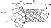
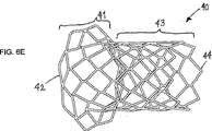
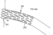
図面を参照すると、図4〜図6には例示的な実施形態によるステント40が図示され、このステントは円筒形状の管状部材からなり、管状部材は、近位端または第1端42および遠位端または第2端44を含み、これらの間に長手方向軸46を形成する。ステント40は、収縮状態あるいは送達状態(図示せず)から、(例えば図5A,図6A,図6Cで図示したように)フレア展開状態(flared condition:朝顔の花が開くように展開した状態)を経て、(例えば図5B,図6B〜図6Eで図示したように)拡大展開状態または完全展開状態に、ほぼ半径方向に拡張することができる。例えば、ステント40は、第1端42に第1の端部部分41と、第1の端部部分41に隣接する第2の部分43と、第2の部分43を第1の端部部分41に連結する複数の連結部10とを有する。
Referring to the drawings, FIGS. 4-6 illustrate a
例示的な実施形態では、ステント40は、近位端42と遠位端44の間に配設された複数の環状のバンド(帯状の)セル47〜49を有する。各バンドセル47〜49は、ステント40に沿って、そして/またはステント40の周囲方向に延びる(例えばジグザクパターンまたは曲がりくねったパターンで延びる)複数のストラット(strut、筋交い)または他の部材により形成して、開口セル構造体を形成することができる。直接的に、あるいは連結部あるいは他の部材を介して、互いに隣接するバンドセルを連結してもよい。
In the exemplary embodiment,
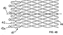
例えば、とりわけ図4Aを参照すると、ステント40の第1の端部部分41を構成する第1および第2のバンドセル47,48を有していてもよい。第1端42における第1のバンドセル47は、一般に、複数の軸方向部材2と交互に連結されたステント40の周囲方向に延びる湾曲部材3とにより構成されたジグザクパターンまたは曲がりくねったパターンを有する。軸方向部材2は、実質的に直線的であり、図4Aに示すように、収縮状態にあるとき、長手方向軸に実質的に平行に延びている。択一的には、軸方向部材2は、より複雑な幾何学的形状を有し、すなわち1つまたはそれ以上の湾曲部または折曲部を有し、軸方向部材と周方向部材(図示せず)の両方を有するものであってもよい。一般に、第1のバンドセル47は、長手方向軸46に実質的に平行な第1の軸方向長さ16を有し、この第1の軸方向長さは、軸方向部材2が長手方向軸に実質的に平行に延びるか、長手方向軸に対して所定の角度で延びるか(すなわち対角線方向または周方向)に依存して、少なくとも部分的には軸方向部材2の長さとして定義される。
For example, with particular reference to FIG. 4A, it may have first and
また、第1のバンドセル47に隣接する第2のバンドセル48は、概略、複数の軸方向部材5と交互に連結されたステント40の周囲に延びる湾曲部材6とにより構成されたジグザクパターンまたは曲がりくねったパターンを有する。図示されているように、第2のバンドセル48は、第1のバンドセル47と実質的に同様の第2の軸方向長さ17を有する。例えば、軸方向部材2,5は実質的に同一の長さを有し、湾曲部材3,6は実質的に同一の曲率半径を有していてもよい。
The
図示したように、軸方向部材2,5は湾曲部材3,6より大きい厚みおよび/または幅を有する。すなわち、以下に詳述するように、湾曲部材3,6の耐力(yield strength)を軸方向部材2,5の耐力よりも小さくして、第1の端部部品41の半径方向のフレア展開を支援することができる。
As shown, the
さらに第2のバンドセル48は、1つまたはそれ以上のストラットまたは他の連結部7を用いて第1のバンドセル47に連結される。一般に、連結部7は、第1および第2のバンドセル47,48のジグザクパターンの隣接するピークの間に延びている。連結部は、例えば、第1および第2のバンドセル47,48の隣接する各ピーク間、すなわち第1端42により近い湾曲部材3,6の間に延びる、比較的に短いストラットであってもよい。択一的には、隣接するピークを互いに対して直接的に、すなわち隣接する湾曲部材3,6同士を連結してもよい。さらなる択一例では、隣接するピークを間欠的(断続的に)に、すなわち連結部を介して間接的または直接的に連結してもよい。例えば、周方向において1つおき、2つおき、3つおき、または4つおきに隣接するピークを互いに連結してもよい。さらに、ステント40は、その第2の部分43を構成する複数の追加的なバンドセル49を有していてもよい。追加的なバンドセル49のそれぞれは、湾曲部材9が交互に連結された軸方向部材8を有していてもよく、ジグザクパターンまたは曲がりくねったパターンを形成し、第3の軸方向長さ19を有する。択一的には、ステント40の第2の部分43を構成する隣接するバンドセル49は、図示したようにリンク11を介して連結してもよいし、直接的に連結してもよい(図示せず)。
Furthermore, the
図示のように、軸方向部材8および湾曲部材9は、軸方向部材2,5および/または湾曲部材3,6より大きい厚みおよび/または幅を有する。例えば、隣接するバンドセル49は、比較的に硬く、そして/または第1および第2のバンドセル47,48より大きい耐力を有していてもよい。すなわち、1つの実施形態では、ステント40の第2の部分43は、実質的に均一な形態を有し、実質的に塑性変形して、拡張することができる。この形態は、小孔から延びる支流血管を拡張させる上で特に有用なものである。
As shown, the axial member 8 and the bending
ステント40の第2の部分43における各バンドセル49は、同様の形態および軸方向長さを有するものとして図示されているが、必要ならば、その寸法および形態において、ステント40の第2端44および第2のバンドセル48とは異なっていてもよいことが理解されよう。すなわち、第2のバンドセル48と第2端44の間のステント部分は、本明細書に記載されているように、実質的に均質のバンドセルであってもよいし、または不均一のセルおよび/またはバンドの形態を有していてもよい。さらに、このステント40を用いて拡張または処置すべき病変部の長さに対応する所定の長さ(3mm〜20mm)を第2の部分43が有するように、任意の数の環状バンド49を設けてもよい。
Each
択一的には、ステント40の(フレア展開前の)第2の部分43は他の形態を有していてもよい。例えば、第2の部分43は、第2の部分に沿って周方向、軸方向、および/または螺旋方向に延びるセルを有していてもよい。セルはスロット付きチューブおよび/または他の材料で形成してもよい。択一的には、第2の部分43は、第1の部分(すなわちフレア展開部分)41から第2端44まで延びる1つまたはそれ以上の螺旋ワイヤ、網目状の複数ワイヤなどの1つまたはそれ以上のワイヤ構造体で形成してもよい。すなわち、第1の部分41は本明細書で詳述するフレア構造を有するものの、第2の部分43は、いくつかの実施形態では、任意の既知の構造体として形成してもよい。
Alternatively, the second portion 43 (before flaring deployment) of the
図4Aに戻って、ステント40の第1の部分41は、複数の連結部10を介して第2の部分43に連結してもよい。例示的な実施形態においては、連結部10は、比較的に薄く、そして/または第1の部分41および/または第2の部分43より容易に変形するものであってもよい。連結部10は、例えば、シヌソイドまたは他の曲線の一部をなすような曲線的なストラットを含むものであってもよい。とりわけ連結部10は、バンドセル47〜49より高い可撓性を有し、そして/または容易に変形するので、以下に詳述するように、第1の部分41のフレア展開または拡張を支援することができる。
Returning to FIG. 4A, the
必要ならば、ステント40の1つの他はそれ以上の部分(または、ここに開示する他の任意の実施形態)は、以下に詳述するようなメンブレン、フィルム、コーティングを有していてもよい。択一的には、ステントは、これを体内に挿入し、配置し、そして/または拡張するときにモニタしやすくするための1つまたはそれ以上の放射線不透過性マーカまたはその他のマーカを有していてもよい。例えば、図4Bは、第1端42から延びる複数のリング42aを有するステント40’を図示している。リング42aは放射線不透過性の材料で形成するか、これをコーティングしてもよい。追加的または択一的には、放射線不透過性材料を内部空間に溶融し、圧着し、レーザ溶接し、または固定することにより、リング42aの内部空間に放射線不透過性材料を充填してもよい。追加的または択一的には、ステント40は、患者の体内の標的部位における治療を促進または改善する1つまたはそれ以上の治療薬または他の物質を担持するようにしてもよい。
If desired, one other portion of stent 40 (or any other embodiment disclosed herein) may have a membrane, film, or coating as detailed below. . Alternatively, the stent has one or more radiopaque markers or other markers to facilitate monitoring as it is inserted, placed and / or expanded into the body. It may be. For example, FIG. 4B illustrates a
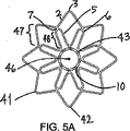
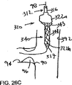
図6A〜図6Eを参照すると、当初ステント40は収縮した状態で提供され、このとき第1の端部部分41は縮減した形状(図示せず)を有し、その形状は図6Aおよび図6Cに示す第2の部品43の縮減した形状と類似するものであってもよい。例えば、収縮した状態において、ステント40は、例えば約0.5mm〜約2mmの間の実質的に均一な直径を有していてもよい。ステント40は、例えば図5A、図6A、および図6Cで示すように第1の端部部分41がフレア展開し、第2の部品43が縮減した状態で維持されるように、フレア展開状態となるように構成してもよい。
Referring to FIGS. 6A-6E, initially the
とりわけ図5Aで最も明らかであるように、第1端42が第2の部品よりはるかに大きい直径または周囲長さを形成するように、第1の端部部分41は拡張する。例えば、第1の端部部分41は、その外径が約3mm〜約12mmの間、例えば約7mmになるまでフレア展開させてもよい。すなわちフレア展開状態においては、第1の端部部分41は、第2の部品43の直径の2倍〜5倍の外径を有することがある。またフレア展開状態においては、第1および第2のバンドセル47,48のストラットの向きを実質的な軸方向から、少なくとも部分的には半径方向または周方向に配向させてもよい。例えば、図5Aで最も明らかであるように、2組目のセル48のストラット5を実質的な軸方向(図示せず、図4A)から半径方向外側に向かって配向させてもよい。
In particular, as best seen in FIG. 5A, the
追加的には、フレア展開状態において、第1のバンドセル47のストラット2の向きを実質的な軸方向から、少なくとも部分的には半径方向または周方向に配向させてもよい(図示せず、図4A参照)。図5Aに示すように、第1の端部部品41がフレア展開するように、ストラット2がコネクタ7により互いに対して引き離すように付勢されるものの、第1のバンドセル47のジグザグパターンは維持される。このとき、第1のバンドセル47の湾曲部分3が可塑的に拡張して、すなわち少なくとも部分的に直線的になり、ストラット2が少なくとも部分的にはステント40の第1端42の周りの周方向に拡張する。
Additionally, in the flare deployed state, the orientation of the
フレア展開状態を実現するための1つの構成要素は可撓性コネクタ10である。コネクタ10は、ステント40の他の構成部品より容易に折り曲げることができるので、第2のバンドセル48を円筒状から花弁状または円錐台状に変形させることができる。すなわちフレア展開状態において、軸46からより離れた湾曲部分6を実質的に変形させないで、軸46により近い湾曲部分6の変形を最小限に抑えることができる。すなわち、コネクタ10がステント40のフレア展開時の拡張により生じるストレスの大部分を吸収することができる。
One component for realizing the flare deployed state is a
さらに、コネクタ10の相対的な可撓性により、第1の端部部品41が90度近くまでフレア展開を支援することができる。第1の端部部品41がフレア展開状態に向かって外側に展開されるとき、第2のバンドセル48は軸方向から半径方向にコネクタの周りをピボット回転し、より急激に折り曲げることができる。例示的な実施形態では、長手方向軸と第2のバンドセル48の間の角度は、約45度〜約90度であってもよい。
Furthermore, the relative flexibility of the
さらに、ステント40の第2の部分43(随意的には第1の端部部品41も同様)を完全に拡張状態または展開状態に拡張させたとき、第1および第2のバンドセル47,48のストラット2,5は、より周方向に配向することができる。とりわけ図5Bを参照すると、第1のバンドセル47のストラット2が実質的に周方向に配向され、湾曲部分3がいっそう直線的になり、第1のバンドセル47がほぼ円形状となって、このときストレスがストラット2および湾曲部分3に実質的に均等に配分される。
In addition, the first and
第1のバンドセル47がほぼ円形状になると、第1のバンドセル47と拡張している第2の部分43との間で第2のバンドセル48が圧縮される。その結果、第2のバンドセル48のストラット5は、互いに対して引き離され、中心軸46の周りに少なくとも部分的に周方向に延びて、湾曲部分6が開く。すなわち、完全に展開した状態においては、第2の部分43の拡張半径に対する第1端42の外径の比は、約1.1〜1.8程度まで小さくなる。十分に展開した状態にあるとき、例えば、第2の部分43の直径は約2mm〜8mmで、第1端42の外径は約4mm〜15mmであってもよい。
When the
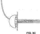
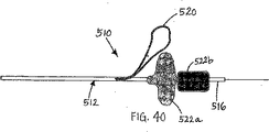
ステント40は、本明細書に開示されるような送達装置を用いて、内視鏡により送達されるものであってもよい。例えば、図6Aおよび図6Bにはバルーンカテーテル10が図示され、これは近位端(図示せず)、遠位端16、および近位端と遠位端の間に延びる1つまたはそれ以上のルーメン(図示せず)を有するカテーテルまたは伸張管状部材12を有する。遠位端16において、1つまたはそれ以上のバルーンあるいは他の拡張可能な部品22、すなわち図示された第1の近位バルーン22aおよび第2の遠位バルーンが配設されている。ステント40は、1つまたはそれ以上の拡張可能部品22を包囲するように、バルーンカテーテル12の遠位端16の周りに配置してもよい。
The
随意的には、この装置10は、ステント40を包囲または被覆することができるシースまたは他のカバー(図示せず)を有していてもよい。シースは、展開前において、ステント40の近位部分および遠位部分あるいはステント全体の上にあったものを移動させて、ステント40を露出させてもよい。追加的にまたは択一的には、ステント40の第1端42および第2端44に隣接して、1つまたはそれ以上の放射線不透過性のマーカ(例えばマーカ29)をカテーテル12上に設けてもよい。
Optionally, the
この装置を用いて、小孔または血管枝(図示せず)、すなわち第2の支流たる体内管腔に連通する第1の主流たる体内管腔の壁部にある開口部内にステント40を送達することができる。例示的な実施形態において、主流体内管腔は大動脈起始部であり、支流体内管腔は冠動脈または腎動脈であってもよい。別の実施形態では、主流体内管腔が大動脈であり、支流体内管腔が腎動脈または他の末梢血管であってもよい。本明細書に記載の装置および方法は、患者の血管系、消化管系または他の脈管系内における主たる体内管腔から横断的に、すなわち横方向または実質的に垂直方向に延びるさまざまな分岐点または支流体内管腔において適用することができる。
This device is used to deliver the
以下に詳述される手法と同様に、まずガイドワイヤまたは他のレールが主流体内管腔から小孔を介して支流に案内される。随意的には、ガイドカテーテルの遠位端が小孔に隣接または近接するまで、ガイドカテーテルをガイドワイヤに沿って挿入してもよい。ガイドカテーテルを用いて、1つまたはそれ以上の器具をガイドワイヤ上で移動させて、主流または支流体内管腔に挿入してもよい。 Similar to the approach described in detail below, a guide wire or other rail is first guided from the main fluid lumen through a small hole to a tributary. Optionally, the guide catheter may be inserted along the guidewire until the distal end of the guide catheter is adjacent or close to the stoma. Using a guide catheter, one or more instruments may be moved over the guidewire and inserted into the mainstream or tributary lumen.
ステント40を収縮させた状態で、装置10の遠位端16が挿入部位からガイドワイヤ上に、そして/またはガイドカテーテルを通って、主流体内管腔まで挿入される。この装置10を用いて、第1端42が小孔に隣接し、第2端44が支流内に配置されるように、ステント40を少なくとも部分的に小孔内に配置する。
With the
図6Aに示すように、第1のバルーン22aを膨張させて、ステント40の第1の端部部分41をフレア展開状態に拡張させる。第1の端部部分41が小孔に隣接して拡張したとき、フレア展開した第1の端部部分41を小孔に当接させるように装置10を挿入してもよい。随意的には、フレア展開した第1の端部部分41を部分的に変形させるのに十分な力で、すなわち第1の端部部分41の外形形状が小孔の形状に少なくとも部分的に整合するのに十分な力で装置10を挿入してもよい。択一的には、以下に説明するように、第1の端部部分41は部分的に小孔内に配置され、ステント40をフレア展開させると、ステント40が部分的に小孔から外へ出るようにしてもよい。
As shown in FIG. 6A, the first balloon 22a is inflated to expand the
図6Bを参照すると、第2のバルーン22bが膨張して第2の部分43が拡張し、そして/または第1の部分41がさらに拡張している。すなわち、第2の部分43が拡張して、支流体内管腔の内壁に係合し、そして/または第1の部分41がさらに拡張して小孔の壁に係合することにより、ステント40を所定位置に実質的に固定することができる。その後、バルーン22を収縮させて、装置10を取り出し、ステント40を小孔内に留置する。
Referring to FIG. 6B, the
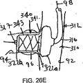
図6Dおよび図6Eに示すように、ステント40は、異なる形状を有する小孔に適合するようにさまざまな形状に拡張させることができる。例えば図6Dに示すように、第1の端部部分41が最小限の傾斜部を有する小孔に適合するように、より急激にフレア展開する一方、第2の部分43は比較的に大きい径に対応するより大きい支流に適合するように、ステント40を拡張させることができる。比較例として、図6Eに示すように、第1の端部部分41がより大きな傾斜形状を有する小孔に適合するように、より緩やかにフレア展開する一方、第2の部分43は比較的に小さい径に対応するより小さい支流に適合するように、ステント40を拡張させることができる。
As shown in FIGS. 6D and 6E, the
ステント40を拡張させている間、ステント40の第1端および第2端の直径または他の断面積の比は変化し得る。例えば上述のように、第1の端部部分41が、例えば中程度にフレア展開したとき、第2の部分43に対する第1の端部部分41の直径の比は比較的に大きく、例えば2〜5である。すなわち第1の端部部分41を比較的に大きくして、小孔に対してステント40を配置しやすくすることができる。ステント40を完全展開状態まで拡張させたとき、第2の部分43に対する第1の端部部分41の比は、例えば1.1〜1.8まで小さくなる。これは、展開後に小孔に対するステント40の均一な分布を実現する上で好ましい。追加的または択一的に、第1の端部部分41が主流たる管腔内に延びるリスクを低減し、そして/またはガイドワイヤや他のデバイスを用いて後に小孔を再び横断させることを支援することができる。
While the
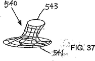
図7を参照すると、別の実施形態によるステント140が図示され、これは第1端142および第2端144を有し、その間に長手方向軸146が形成されている。一般に、ステント140は、先の実施形態と同様、第1の部分またはフレア展開部141と、第2の部分または本体部143とを有する。
Referring to FIG. 7, a
先の実施形態と同様、ステント140は、その第1の端部部品141を構成する第1および第2のバンドセル147,148を有する。第1端142にある第1のバンドセル147は、一般に、複数の軸方向部材102と交互に連結されたステント140の周囲に延びる湾曲部材103とにより構成されたジグザグパターンまたは曲がりくねったパターンを有する。軸方向部材102は、実質的に直線的であり、図7に示すように、収縮状態にあるとき、長手方向軸に実質的に平行に延びている。
Similar to the previous embodiment, the
第1のバンドセル147は、一般に、長手方向軸146に実質的に平行な第1の軸方向長さ118を有する。第1の軸方向長さ118は、軸方向部材102が図示のように長手方向軸に対して実質的に平行に延びるか、長手方向軸に対して所定の角度で延びるか(図示せず)に依存して、少なくとも部分的には軸方向部材102の長さとして定義される。
The
また第1のバンドセル147に隣接する第2のバンドセル148は、一般に、複数の軸方向部材105と交互に連結されたステント140の周囲に延びる湾曲部材106とにより構成されたジグザグパターンまたは曲がりくねったパターンを有する。図示のように、第2のバンドセル148は、第1のバンドセル147と実質的に同様に、軸方向長さ117を有する。軸方向部材102,105は実質的に同じ長さであってもよく、湾曲部材103,106は実質的に同じ曲率半径を有していてもよい。図示の実施形態では、第1および第2のバンドセル147,148は互いに対して実質的に鏡像関係にある。
Also, the
図示のように、軸方向部材102,105は湾曲部材103,106より大きい厚みおよび/または幅を有する。すなわち、本明細書で開示するように、湾曲部材103,106の耐力を軸方向部材102,105の耐力よりも小さくして、第1の端部部品141の半径方向のフレア展開を支援することができる。
As shown, the
さらに第2のバンドセル148は、1つまたはそれ以上のストラットまたは他の連結部107を用いて第1のバンドセル147に連結される。一般に、連結部107は、第1および第2のバンドセル147,148のジグザクパターンの隣接するピークの間に延びている。連結部107は、例えば、第1および第2のバンドセル147,148の隣接する各ピーク間、すなわち第1端142により近い湾曲部材103,106の間に延びる、比較的に短いストラットであってもよい。択一的には、隣接するピークを互いに対して直接的に、すなわち隣接する湾曲部材103,106同士を連結してもよいし、そして/または、他の実施形態と同様に、第1および第2のバンドセル147,148を間欠的にのみ連結してもよい。さらに別の択一例では、シヌソイド状のストラット(図示せず)を介して第1および第2のバンドセル147,148を連結してもよい。
Further, the
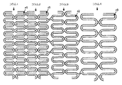
続けて図7を参照すると、ステント140の第2の本体部143は、その長さ方向に沿って互いに連結された複数のバンドセル149を有する。各バンドセル149は、湾曲部材109に交互に連結された軸方向部材108を有し、ジグザクパターンまたは曲がりくねったパターンを形成して、第3の軸方向長さ119を定義する。随意的には、ステント140の第2の本体部143を構成する隣接するバンドセル149はリンク111を介して連結してもよい。リンク111は、ほぼシヌソイド波状または他の曲線形状をなす少なくとも一部を構成するストラットであってもよい。択一的には、リンク111は軸方向ストラット(図示せず)であってもよいし、あるいは隣接するバンドセル149は、隣接する湾曲部材109(同様に図示せず)を用いて直接的に連結してもよい。リンク111は、湾曲部材109に比べて相対的に狭小で、そして/または薄く、ステント140の第2の本体部143の折曲性または従順性を助長するものであってもよい。例示的な実施形態では、第2の本体部143のバンドセル149は、第1のフレア展開部141のバンドセル147よりより大きな半径方向の力(強度)を有していてもよい。例えば、軸方向部材108および湾曲部材109は、それぞれ軸方向部材102,105および湾曲部材103,106よりも大きな厚みおよび/または幅を有していてもよい。このためバンドセル149は、第1および第2のバンドセル147,148に比して相対的に固く、そして/またはより大きな耐力(yield strength)を有することができる。例えば、バンドセル149は、より大きな半径方向の力を有し、バンドセル147,148に比して、管腔としてのより大きな支持力を実現することができる。追加的または択一的には、バンドセル149は、バンドセル147,148に比して、膨張に対するより大きな抵抗力を有し、以下に詳述するように、フレア展開部141がフレア展開したとき、フレア展開部141に最も近接するバンドセル149の拡張を最小限に抑えることができる。
With continued reference to FIG. 7, the
上述の実施形態とは異なり、第2の本体部143は、互いに異なる特性を有する近位側本体部143aと遠位側本体部143bとを有する。以下に詳述するように、例えば、小孔の拡張を支援するために、近位側本体部143aは遠位側本体部143bより大きな半径方向の力を有していてもよい。近位側本体部143aの半径方向の力を増大させるためには、軸方向部材108aおよび/または湾曲部材109aが軸方向部材108bおよび/または湾曲部材109bより大きな幅を有していてもよい。例示的な実施形態において、部材108a,109aは、部材108b,109bの約15%〜約50%に相当する約0.007インチ〜約0.009インチ(約0.18mm〜約0.23mm)の幅を有していてもよい。択一的には、近位側本体部143aおよび遠位側本体部143bに関して、例えば、厚みおよび長さなどの1つまたはそれ以上の他の寸法、ならびに/またはセル構造を変更して、近位側本体部143aの相対的な半径方向の力および/または剛性を遠位側本体部143bより増大させることができる。
Unlike the above-mentioned embodiment, the 2nd main-
ステント140を用いて拡張または処置される病変部の長さ(例えば、約3mm〜約20mm)に応じて、第2の本体部143が所定の長さを有するように、任意の数の環状バンド149を配置してもよいことが理解されよう。近位側本体部143aおよび遠位側本体部143bは、複数のバンドセル149a,149bを有していてもよい。例示的な実施形態では、遠位側本体部143bは、近位側本体部143aより数多くのバンドセル149bを有していてもよい。図示のように、例えば、近位側本体部143aは2つのバンドセル149aを有し、遠位側本体部143bは少なくとも3つ、4つ、5つ、6つ、あるいはそれ以上のバンドセル149bを有していてもよい。すなわち、以下に詳述するが、近位側本体部143aは小孔の直ぐ近くに配設されるのに対し、遠位側本体部143bは処置すべき病変部(図示せず)全体にわたって、かつそれ以上に延びるものであってもよい。
Depending on the length of the lesion to be expanded or treated using the stent 140 (eg, about 3 mm to about 20 mm), any number of annular bands so that the
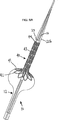
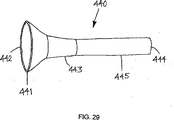
図8および図9を参照すると、例示的な実施形態に係る送達装置110が図示されており、送達装置はカテーテルまたは伸張管状部材112を有し、カテーテルは近位端(図示せず)、遠位端116、および近位端と遠位端の間に延びる1つまたはそれ以上のルーメン(図示せず)を有する。遠位端116において、1つまたはそれ以上のバルーンあるいは他の拡張可能な部品22、すなわち第1の近位バルーン122aおよび第2の遠位バルーン122bがカテーテル112の遠位先端部117に隣接して配設されている。送達装置110を作製する材料および方法は、2006年5月25日付けで出願された米国特許出願公開第11/136,266号に開示されている。加えて、送達装置110は、例えば、生理食塩水または他の流体で充填された、各バルーン122と流体連通する1つまたはそれ以上のシリンジなどの1つまたはそれ以上の膨張手段(図示せず)を有していてもよい。
With reference to FIGS. 8 and 9, a
一般に、バルーン122は、収縮状態(図9に示す)から拡張状態(図8に示す)に拡張させることができる。各バルーン122a,122bは、独立して膨張および収縮させることができるように、カテーテル112内のそれぞれの膨張ルーメン(図示せず)と連通している。例示的な実施形態では、近位バルーン122aは、ポリエチレン、ポリウレタン、低程度または中程度の硬さ(durometer)のPEBAXなどの実質的な弾性あるいは半弾性を有する材料を用いて作製され、第2の遠位バルーン122bは、半弾性または実質的な非弾性を有する材料を用いて作製され、中程度または高程度の硬さ(durometer)のPEBAX、ナイロン、PETなどを用いて作製される。
In general, the
追加的または択一的には、各バルーン122は、異なる内圧および/またはそれぞれを完全に拡張させるために十分な圧力を必要とするものであってもよい。例えば、遠位バルーン122aは、近位バルーン122bを完全に拡張させるために、より大きな膨張圧力を必要とするものであってもよい。このとき以下に詳述するように、近位バルーン122aをより小さい膨張圧力で拡張させ、ステントの本体部を実質的に膨張させることなく、ステントのフレア展開部をフレア展開または形成することができ、したがって、より高圧の膨張圧を用いて、遠位バルーン122bを拡張させ、ステントの本体部を膨張させて、閉塞部または小孔に隣接する他の病変部の拡張を支援することができる。
Additionally or alternatively, each
択一的には、以下に詳述するように、使用中、近位バルーン122aは、1つまたはそれ以上の所定量の流体の供給に基づいて、すなわち複数の段階で膨張させてもよい。近位バルーン122aは、例えば約0.25〜約2cm3の第1の所定量の流体が供給されると部分的に膨張し、装置110を配置する前にステントがフレア展開する。ステントを配置し、遠位バルーン122bを拡張させた後、以下説明するように、ステントをフレア展開させ、形成するために、例えば約0.5〜約4.2cm3のより容量の大きい第2の所定量の流体を供給することにより、近位バルーン122aを完全に膨張させてもよい。近位バルーン122aの相対的な弾性および/または低い圧力が要請されることから、所定量に基づく供給は、近位バルーン122aの機能を記述する上で有用である。
Alternatively, as described in detail below, in use, the
任意的には、近位バルーン122aと連通する膨張手段のソースは、近位バルーン122aを2段階で膨張させることを支援するために、第1の所定容量または第2の所定容量を順次供給するために、ソースを同定または規制するための標識または他の特徴部品を有していてもよい。例えば、シリンジは第1位置マーカおよび第2位置マーカ(図示せず)を有していてもよい。シリンジのプランジャを第1位置マーカまで押下すると、これに呼応して、第1の所定容量の流体が近位バルーン122a内に供給される。シリンジのプランジャを第2位置マーカまでさらに押下すると、これに呼応して、第2の所定容量の流体が近位バルーン122a内に供給される。
Optionally, a source of inflation means in communication with the
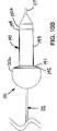
図8に示すように、近位バルーン122aは、拡張状態において実質的に球形形状に膨張するように形成されており、約1気圧〜約5気圧の膨張圧力を用いたとき、約10mm〜約20mmの直径を有する。例示的な実施形態では、近位バルーン122aは、約2気圧の膨張圧力で約13mmの直径を有する。対称的に、遠位バルーン122bは、拡張状態において実質的に円筒形状に膨張するように形成されており、約8気圧〜約20気圧の膨張圧力を用いたとき、約2mm〜約8mmの直径を有する。
As shown in FIG. 8, the
加えて、遠位バルーン122bは、約8mm〜約30mmの均一な直径を有する部分を含んでいてもよい。均一直径部分を超えると、遠位バルーン122bは、遠位先端部117に隣接した移行部分122cを含んでいてもよい。移行部分122cは、傾斜しており、図示のように実質的に尖っておらず、遠位先端部117に内側に延びている(図示せず)。随意的には、遠位バルーン122bは、近位バルーン122aの少なくとも一部の基礎をなすものであってもよい。例示的な実施形態では、遠位バルーン122bは、拡張状態で約6mmの直径を有し、近位バルーン122aから遠位方向にさらに約17mmの長さを有するものであってもよい。
In addition, the
とりわけ図9を参照すると、ステント140はカテーテル112の遠位端116の周りに取り付けられ、バルーン122の少なくとも一部を包囲するものであってもよい。一般に、ステント140の第1のフレア展開部141が近位バルーン122a(例えば近位バルーン122aの遠位端)上に重畳し、ステント140の遠位側の本体部143bが遠位バルーン122bの上(すなわち近位バルーン122aと移行部分122cの間)に重畳するようにしてもよい。ステント140の近位側の本体部143aは、近位バルーン122aおよび遠位バルーン122bの一方または両方の上を重畳するものであってもよい。例えば図示のように、1つのバンドセル149aの少なくとも一部が近位バルーン122aを重畳し、バンドセル149aの残りの部分が遠位バルーン122bに重畳するようにしてもよい。このようにステント140の近位側の本体部143aを重畳させることにより、上記説明したように、ステント140が急勾配でフレア展開することを可能にする。
With particular reference to FIG. 9, the
随意的には、本明細書で説明する他の実施形態と同様、送達装置110は、ステント140を包囲またはカバーするシースまたは他の被覆材(図示せず)を有していてもよい。このシースは、ステント40が展開する前に、ステント40の近位側および遠位側の本体部の上から、あるいはステント40の全体の上から取り外しできるものであってもよい。
Optionally, like other embodiments described herein, the
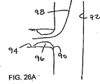
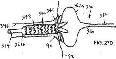
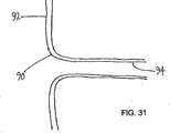
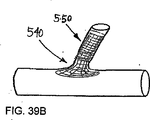
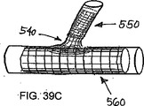
図11A〜図11Dを参照すると、本明細書で説明する他の実施形態と同様、装置110を用いて、小孔90の中に、すなわち第1の主流体内管腔92と第2の支流体内管腔94の間で連通する開口部の中に、ステント140を送達することができる。
Referring to FIGS. 11A-11D, similar to the other embodiments described herein, the
最初に、ガイドワイヤまたは他のレール90(例えば図11Dを参照)が主流体内管腔92から小孔90を介して支流に案内される。ガイドワイヤは、例えば経皮的穿刺部位または他の注入部位から、大腿動脈または頸動脈などの末梢血管内に、患者の脈管系を介して主流体内管腔92と支流体内管腔まで挿入することができる。随意的には、図11Aに示すように、ガイドカテーテル160の遠位端164が小孔90に隣接または近接するまで、ガイドカテーテル160をガイドワイヤの上に沿って主流体内管腔92内に挿入してもよい。
Initially, a guide wire or other rail 90 (see, eg, FIG. 11D) is guided from the
ステント140を収縮させた状態で、装置110の遠位端116は、ガイドワイヤの上に沿って、そして/またはガイドカテーテル内を通して、注入部位から主流体内管腔92内に挿入される。この装置110は、小孔90内に少なくとも部分的に収まるように配置される。例えば、図11Aに示すように、ステント140および/またはバルーン122が処置すべき病変部と少なくとも部分的に交差する(重なる)ように、装置110の遠位端116は小孔90から支流体内管腔94まで挿入される。装置110を引き出して、ステント140の少なくともフレア展開部141は主流体内管腔92内に留置される。
With the
図11Bを参照すると、近位バルーン122aを膨張させてステント140のフレア展開部141を拡張させ、すなわち上述のように、第1および第2のバンドセル147,148を軸方向形態から周辺および/または半径方向形態に変形させる。
Referring to FIG. 11B, the
例えば上記説明したように、近位バルーン122aを部分的に拡張させるために、第1の所定容量の流体を近位バルーン122aに供給してもよい。ステント140の近位側本体部143aの一部は近位バルーン122aを重畳するものであるが、近位側本体部143aの半径方向の力がより大きいこと、および/または近位バルーン122aを膨張させるために用いられる膨張圧が比較的に小さいことなどに起因して、近位側本体部143aは膨張を抑制するものであってもよい。すなわちフレア展開部141は、比較的に急勾配にフレア展開させることができる。
For example, as described above, a first predetermined volume of fluid may be supplied to the
装置110はフレア展開部141が小孔90に接触するように挿入してもよい。また随意的には装置110は、フレア展開部141が部分的に変形するのに十分な力で、例えば小孔90の外形形状と部分的に一致(整合)するために要する力で挿入してもよい。択一的には、フレア展開部141が小孔90内に少なくとも部分的に配置されている場合、近位バルーン122aを膨張させると、以下詳述するように、フレア展開させることにより、ステント140の一部が小孔90から外側に移動することがある。
The
随意的には、透視画像技術または他の画像技術を用いて、処置中の装置110および/またはステント140をモニタ(監視)して、ステント140が小孔90内の適正な位置に配置されていることを確認するようにしてもよい。このオプションにおいて、ステント140および/または装置110は、上記説明したように、放射線不透過性マーカなど(図示せず)を有していてもよい。
Optionally, fluoroscopic or other imaging techniques are used to monitor the
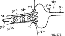
図11Cを参照すると、ステント140を適正に配置したとき、遠位バルーン122bを膨張させて、ステント140の本体部143を拡張させ、そして/またはフレア展開部141をさらに展開させる。例えば、小孔および/または支流体内管腔の内壁に係合するように近位側本体部143aを拡張させ、支流体内管腔の内壁に係合するように遠位側本体部143bを拡張させて、病変部を押し広げ、ステント140を所定位置に実質的に固定する。本体部143の半径方向の力がより大きいため、遠位バルーン122bは、近位バルーン122aより強い圧力で膨張し、病変部を押し広げるように本体部143を拡張させることができる。
Referring to FIG. 11C, when the
本体部143が拡張すると、拡張された本体部143と支流体内管腔の間の摩擦力またはその他の係合により、支流体内管腔に対してステント140を実質的に軸方向に固定することができる。必要ならば、第2の所定容量の流体をさらに供給して、近位バルーン122aをさらに拡張させることができる。すると、ステント140のフレア展開部141をさらにフレア展開させ、そして/またはフレア展開部141を小孔の壁部に圧接させることができる。近位バルーン122aをさらに拡張させることによりフレア展開部141に追加される流体圧力は、装置110を手動で小孔内に挿入することにより得られる圧力より大きくすることができる。
When the
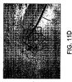
図11Dを参照すると、バルーン122を膨張させた後、装置110を取り出して、ステント140を小孔90および支流体内管腔94内に留置することができる。近位側本体部143aの半径方向の力がより強いので、ステント140のこの部分は、周辺組織による圧縮力に対する抵抗力を増強することができる。例えば、いくつかの応用例では、体内管腔を包囲する組織は、とりわけ小孔のネック部において萎縮(反発)する傾向があり、すなわち半径方向内側に収縮する傾向がある。すなわち、ステント140の本体部143、とりわけ小孔90内に配置された近位側本体部143aが、こうした萎縮に対して抵抗し、小孔を無期限に開口状態に維持することができる。
Referring to FIG. 11D, after the
図12を参照すると、さらに別の実施形態に係るステント240が図示されており、このステントは、第1端242および第2端244を有し、その間に長手方向軸246が形成されている。一般に、ステント240は、先の実施形態と同様、第1の部分またはフレア展開部241と、第2の部分または本体部243とを有する。
Referring to FIG. 12, a
また先の実施形態と同様、ステント240は、その第1の端部部品241を構成する第1および第2のバンドセル247,248を有する。第1端242にある第1のバンドセル247は、一般に、複数の軸方向部材202と交互に連結されたステント240の周囲に延びる湾曲部材203とにより構成されたジグザグパターンまたは曲がりくねったパターンを有する。軸方向部材202は、実質的に直線的であり、図12に示すように、収縮状態にあるときの長手方向軸に実質的に平行に延びている。第1のバンドセル247は、一般に、長手方向軸246に実質的に平行な第1の軸方向長さ216を有する。第1の軸方向長さ216は、軸方向部材202が図示のように長手方向軸246に対して実質的に平行に延びるか、長手方向軸に対して所定の角度で延びるか(図示せず)に依存して、少なくとも部分的には軸方向部材102の長さとして定義される。
Also, similar to the previous embodiment, the
また第1のバンドセル247に隣接する第2のバンドセル248は、一般に、複数の軸方向部材205と交互に連結されたステント240の周囲に延びる湾曲部材206とにより構成されたジグザグパターンまたは曲がりくねったパターンを有する。図示のように、第2のバンドセル248は、第1のバンドセル247と実質的に同様に、軸方向長さ217を有する。例えば、軸方向部材202,205は実質的に同じ長さであってもよく、湾曲部材203,206は実質的に同じ曲率半径を有していてもよい。図示の実施形態では、第1および第2のバンドセル247,248は互いに対して実質的に鏡像関係にある。
Also, the
図示のように、軸方向部材202,205は、湾曲部材203,206よりも大きな厚みおよび/または幅を有する。すなわち、湾曲部材203,206の耐力は、軸方向部材202,205より小さく、上述のように、第1の端部部分241の半径方向のフレア展開を支援することができる。
As shown, the axial members 202, 205 have a greater thickness and / or width than the curved members 203, 206. That is, the proof stress of the bending members 203 and 206 is smaller than that of the axial members 202 and 205, and can support the flare deployment in the radial direction of the
さらに、第2のバンドセル248は、1つまたはそれ以上のストラットまたは他の連結部207を用いて第1のバンドセル247に連結するようにしてもよい。一般に、連結部207は、第1および第2のバンドセル247,248のジグザクパターンの隣接するピークの間に延びている。連結部207は、例えば、第1および第2のバンドセル247,248の隣接する各ピーク間、すなわち第1端242により近い湾曲部材203,206の間に延びる、比較的に短いストラットであってもよい。択一的には、隣接するピークを互いに対して直接的に、すなわち隣接する湾曲部材203,206同士を連結してもよいし、そして/または、第1および第2のバンドセル247,248を間欠的にのみ連結してもよい。さらに別の択一例では、シヌソイド状のストラット(図示せず)を介して第1および第2のバンドセル247,248を連結してもよい。
Further, the
続けて図12を参照すると、ステント240の第2の本体部243は、その長さ方向に沿って互いに連結された複数のバンドセル249を有する。各バンドセル249は、湾曲部材209に交互に連結された軸方向部材208を有し、ジグザクパターンまたは曲がりくねったパターンを形成して、第3の軸方向長さ219を定義する。随意的には、ステント240の第2の本体部243を構成する隣接するバンドセル249はリンク211を介して連結してもよい。リンク211は、ほぼシヌソイド波状または他の曲線形状をなす少なくとも一部を構成するストラットであってもよい。択一的には、リンク211は軸方向ストラット(図示せず)であってもよいし、あるいは隣接するバンドセル249は、隣接する湾曲部材209(同様に図示せず)を用いて直接的に連結してもよい。リンク211は、湾曲部材209に比べて相対的に狭小で、そして/または薄く、ステント240の第2の本体部243の折曲性または従順性を助長するものであってもよい。
With continued reference to FIG. 12, the
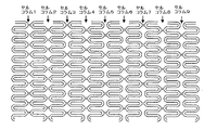
先の実施形態とは異なり、図12に示すように、隣接するバンドセル249は、互いに対して間欠的(非連続的)に連結されている。上述とは異なり、リンク211は、ステント240の周囲に設けた湾曲部材209の対向する組を1つおきにのみ配置される。間欠的に設けた連結部は他の構成を有していてもよく、ステント240の周囲に設けた湾曲部材209の対向する組を2つおき、3つおき、または4つおきに配置してもよい。
Unlike the previous embodiment, as shown in FIG. 12,
湾曲したリンク211および間欠的に設けたリンク211の組み合わせにより、ステント240の軸方向の圧縮性を増長することができる。例えばリンク211により、隣接するバンドセル249が互いに向かって、あるいは互いから遠ざかって移動し、そして/または局所的に移動することを可能にする。すなわち(ステント240を形成するセルの全体的な構成および構造により制限されるとき)特に、リンク211により互いに連結されていない対向湾曲部材209は、互いに向かって、あるいは互いから遠ざかるように自由に移動させることができる。以下詳述するように、この特徴により、少なくともいくつかのバンドセル249は、小孔および/または支流体内管腔内で展開するときに軸方向に圧縮することができ、その結果ステント240をシール(封止)することを支援し、小孔における支持力を増大させることができる。
The axial compressibility of the
いくつかの上記実施形態と同様、第2の本体部243のバンドセル249は、第1のフレア展開部241のバンドセル247,248より強い半径方向の力(強度)を有していてもよい。例えば、軸方向部材208および湾曲部材209は、それぞれ軸方向部材202,205および/または湾曲部材203,206よりも大きな厚みおよび/または幅を有していてもよい。このためバンドセル249は、第1および第2のバンドセル247,248に比して相対的に固く、そして/またはより大きな耐力を有することができる。例えば、バンドセル249は、より大きな半径方向の力を有し、バンドセル247,248に比して、管腔としてのより大きな支持力を実現することができる。追加的にまたは択一的には、バンドセル249は、バンドセル247,248に比して、膨張に対するより大きな抵抗力を有し、以下に詳述するように、フレア展開部241がフレア展開したとき、フレア展開部241に最も近接するバンドセル249の拡張を最小限に抑えることができる。
As in some of the above-described embodiments, the
随意的には、上記実施形態と同様、第2の本体部243は、互いに異なる特性を有する近位側本体部243aと遠位側本体部243bとを有する。例えば、小孔の拡張を支援するために、そして/または萎縮(反動)に対する抵抗力を増大させるために、近位側本体部は遠位側本体部より大きな半径方向の力を有していてもよい。例示的な実施形態では、近位側本体部を構成する部材は、遠位側本体部を構成する部材より大きく、約0.007インチ〜約0.009インチ(約0.18mm〜約0.23mm)の幅を有していてもよい。択一的には、近位側本体部および遠位側本体部において、例えば、厚みおよび長さなどの1つまたはそれ以上の他の寸法、ならびに/またはセル構造を変更して、近位側本体部の相対的な半径方向の力および/または剛性を遠位側本体部より増大させることができる。
Optionally, similar to the above embodiment, the
ステント240を用いて拡張または処置される病変部の長さ(例えば、約3mm〜約20mm)に応じて、第2の本体部243が所定の長さを有するように、任意の数の環状バンド249を配置してもよいことが理解されよう。
Depending on the length of the lesion to be expanded or treated using the stent 240 (eg, about 3 mm to about 20 mm), any number of annular bands so that the
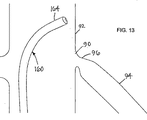
図13〜図19を参照すると、ステント240が小孔90に送達され、本明細書で説明する装置および手法を用いて、小孔90の中に、すなわち第1の主流体内管腔92と第2の支流体内管腔94の間で連通する開口部の中に、ステント240を送達することができる。例示的な実施形態では、主流体内管腔92は大動脈であってもよく、支流体内管腔94は閉塞部または他の病変部を有する冠動脈または腎動脈であってもよい。ステント240は、横断的に、すなわち横方向または実質的に垂直方向に延びるさまざまな分岐点または支流体内管腔内に移植できることが理解されよう。
Referring to FIGS. 13-19, a
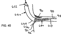
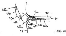
最初に、図13に示すように、ガイドカテーテル160の遠位端164が小孔90に隣接または近接するまで、ガイドカテーテル160は主流体内管腔92内に挿入される。随意的には、図14に示すように、ガイドワイヤまたは他のレール98は主流体内管腔92から小孔90を介して、すなわちガイドカテーテル160を通して支流内に案内される。例えば、遠位端164が小孔90に係合するまで、ガイドカテーテル160を挿入または操作するとともに、ガイドワイヤ98はガイドカテーテル160を通して病変部96まで挿入される。血管を介した施術の場合、既知の手法を用いて、ガイドワイヤ98は、経皮的穿刺部位または他の注入部位(図示せず)から患者の血管を通して主流および支流体内管腔92,94へ挿入される。択一的には、ガイドワイヤ98はガイドカテーテル160の前に、あるいはガイドカテーテルとは個別に案内するようにしてもよい。
First, as shown in FIG. 13, the
上述の装置および手法と同様、図14に示すように、ステント240は(上記の任意の実施形態に係る)送達装置110に装填することができる。例えば、収縮した状態のステント240を有する装置110の遠位端116において、ステント240は近位バルーン122aおよび遠位バルーン122bの上に配設してもよい。この装置110の遠位端116は、ガイドワイヤ98の上に沿って、そして/またはガイドカテーテル160を通って、注入部位から主流体内管腔92まで挿入される。
Similar to the devices and techniques described above, as shown in FIG. 14, the
例えば、図14に示すように、ステント240および/またはバルーン122が処置すべき病変部と少なくとも部分的に交差するように、装置110の遠位端116は小孔90から支流体内管腔94まで挿入される。その後、ガイドカテーテル160は少なくとも部分的に引き出され、装置110の近位バルーン122aを露出させる。必要ならば、装置110は少なくとも部分的に引き出され、ステント240の少なくともフレア展開部241が主流体内管腔92内に留置される。
For example, as shown in FIG. 14, the
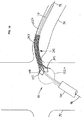
図15を参照すると、近位バルーン122aを膨張させてステント140のフレア展開部141を拡張させ、すなわち上述のように、第1および第2のバンドセル247,248を軸方向形態から周辺および/または半径方向形態に変形させる。例えば上記説明したように、近位バルーン122aを部分的に拡張させるために、第1の所定容量の流体を近位バルーン122aに供給してもよい。随意的には、ステント140の本体部の一部は近位バルーン122aを重畳するものであるが、近位側本体部の半径方向の力がより大きいこと、および/または近位バルーン122aを膨張させるために用いられる膨張圧が比較的に小さいことなどに起因して、近位側本体部は膨張を抑制するものであってもよい。すなわちフレア展開部241は、近位側本体部から比較的に急勾配に外側にフレア展開して、例えば装置110が再び小孔90内に挿入されるとき、機械的な係止部を構成することができる。
Referring to FIG. 15, the
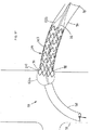
図16を参照すると、その後フレア展開部241を小孔90に当接させるように、装置110を小孔90内に挿入してもよい。これは、近位端(図示せず)から装置110を押し込み、病変部98を通って少なくとも部分的に支流体内管腔内に遠位端116を挿入することにより実現することができる。択一的には、ガイドカテーテル160を遠位方向に挿入して、拡張した近位バルーン122aに遠位端116を押圧してもよい。
ガイドカテーテル160をさらに挿入すると、近位バルーン122aを遠位方向に押圧して、装置110が小孔90内に自動的に挿入されるようにしてもよい。
Referring to FIG. 16, the
Upon further insertion of the
随意的には、フレア展開部241を部分的に変形させるのに十分な力で、すなわちフレア展開部241の外形形状が小孔の形状に少なくとも部分的に整合するのに十分な力で装置110を挿入してもよい。択一的には、以下に説明するように、フレア展開部241の一部が小孔内に配置されると、近位バルーン122aをフレア展開させたときに、フレア展開したステント240が部分的に小孔90から外へ出るようにしてもよい。
Optionally, the
随意的には、透視画像技術または他の画像技術を用いて、処置中の装置110および/またはステント240をモニタ(監視)して、ステント240が小孔90内の適正な位置に配置されていることを確認するようにしてもよい。このオプションにおいて、ステント240および/または装置110は、所定位置に設けた1つまたはそれ以上の放射線不透過性マーカなど(図示せず)を有していてもよい。
Optionally, fluoroscopic imaging techniques or other imaging techniques are used to monitor the
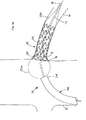
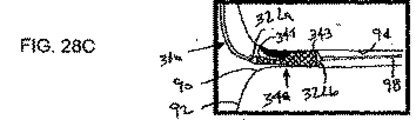
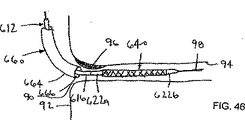
図17を参照すると、ステント240を適正に配置したとき、遠位バルーン122bを膨張させて、ステント240の本体部243を拡張させ、そして/またはフレア展開部241をさらに展開させる。例えば、小孔90および/または支流体内管腔94の内壁に係合するように近位側本体部143aを十分に拡張させて、ステント240および/または装置を小孔90および/または支流体内管腔94に実質的に固定するようにしてもよい。例えば、本体部243を支流体内管腔94および/または小孔90の内壁に係合するように十分に拡張させて、ステント240および/または装置を支流体内管腔94および/または小孔90に実質的に固定するようにしてもよい。随意的には、本体部243は、特性の異なる近位部分と遠位部分を有し、このため上述のように病変部98を押し広げ、かつ/あるいはステント140を所定位置に実質的に固定するように拡張することができる。
Referring to FIG. 17, when the
図18を参照すると、本体部243を拡張させ、ステント240を支流体内管腔94内に実質的に固定すると、第2の所定容量の流体を供給することにより、近位バルーン122aをさらに拡張させる。すると、ステント240のフレア展開部241をさらにフレア展開させ、そして/またはフレア展開部241を小孔90の内壁に圧接させることができる。このように拡張させるとき、以下説明するように、ステント240をさらに変形させて、本体部243を軸方向に圧縮させることができる。
Referring to FIG. 18, when the
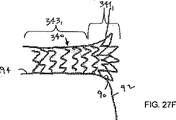
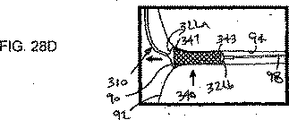
最後に、図19を参照すると、バルーン122を収縮させ、装置110を取り出して、ステント240を小孔90および/または支流体内管腔94に留置することができる。バルーン122の圧力を下げると(バルーン122を収縮させると)、ステント240のフレア展開部241は、バルーン122が膨張しているときより小さい角度をなすように、主流体内管腔92により定義される軸に対して回転する。これは、図18の「角度1」より小さい図19の「角度2」として図示されている。こうした変化は、ステント240および周辺組織が、ステント240および支流体内管腔の内壁が保持する弾性力の間において、新しい機械的平衡状態に達するためである。
Finally, referring to FIG. 19, the
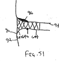
図20Aおよび図20Bを参照すると、近位バルーン122aが完全に膨張しているときのステント240の形態変化がより詳細に図示されている。図20Aに示すように、近位バルーン122aが完全に膨張する前に(ただし遠位バルーン122bが拡張した後)、ステント240は、フレア展開部241の長さおよび本体部243の長さ(Lフレア,L1〜L6の合計)の和として定義される第1の長さ(L合計)を有する。さらに図12を参照すると、長さL1〜L6は複数のバンドセル249の長さにより少なくとも部分的に定義される。長さL1〜L6は、図12で明らかなように、当初は実質的に同一であってもよいが、図20Aに示すように、部分的に拡張することにより変化してもよい。
Referring to FIGS. 20A and 20B, the change in shape of the
ステント240を小孔90に留置しやすくするために、少なくともいくつかの長さ、例えば長さL1,L2,L3は、膨張時には短くなってもよい。例えば、図20Bに示すように、近位バルーン122aを完全に膨張させる際に、ステント240を軸方向にさらに圧縮させてもよい。すなわちステント240は、L合計より短い新たな全体長さ(L合計)を有するものであってもよい。また、本体部243のバンドセル249を互いに対していっそう縮小させてもよい。例えば、小孔90に最も近いバンドセル249をさらに短くして、小孔90から離れたバンドセル249を支流体内管腔94に対して実質的に固定された状態で維持してもよい。すなわち、図20Bの少なくともいくつかの長さ、例えば長さL1’,L2’,L3’は、図20Aの長さL1,L2,L3と比較してより短くしたものであってもよい。
In order to facilitate placement of the
バンドセル249を間欠的に連結することにより、このように長さを短縮しやすくし、その結果、病変部96におけるストラットの密度を増大させることができる。すなわち、小孔90に対するステント240を適合しやすくすることに加え、ステント240を軸方向に圧縮して病変部96における支持力を増大させることができる。小孔90は、支流体内管腔よりも厚く、そして/またはより弾性的な壁部を有することがあるので、病変部96および/または小孔90の径がより小さくなって萎縮することを防止するために、ステント240はより大きな付勢力を有していてもよい。
By intermittently connecting the
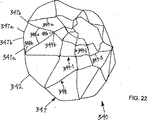
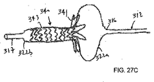
図21〜図23を参照すると、別の実施形態に係るステント340が図示され、このステントは、近位端または第1端342および遠位端または第2端344を含み、これらの間に長手方向軸346を形成するほぼ円筒形状の管状部材を有する。ステント340は、収縮状態あるいは送達状態(図21A)から、拡張状態または展開状態(図21B)にほぼ半径方向に拡張することができる。ステント340は、近位端および遠位端の間に配置された複数の環状バンドセル347〜349を有する。各バンドセル347〜349は、軸方向に沿って延び、そして/またはステント34の周方向に延びるジグザクパターンまたは曲がりくねったパターンを有するストラットまたはその他の部材で構成され、開口セル構造体を形成している。上記実施形態と同様、これらの隣接するバンドセルは直接的にまたは連結部や他の部材を介して連結されている。
Referring to FIGS. 21-23, a
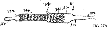
図23に示すように、ステント340は、第1端342において第1のバンドセル347を有し、第1のバンドセルは、複数の軸方向部材347aと交互に連結されたステント340の周囲に延びる湾曲部材347bとにより構成されたジグザクパターンまたは曲がりくねったパターンを有する。軸方向部材347aは、実質的に直線的であり、図21Aに示すように、収縮状態にあるときの長手方向軸に実質的に平行に延びている。択一的には、軸方向部材347aは、他の実施形態と同様、より複雑な幾何学的形状を有していてもよい。図23を参照して、第1のバンドセル347は、一般に、長手方向軸346に実質的に平行な第1の軸方向長さ347cを有するが、この第1の軸方向長さは、軸方向部材347aが長手方向軸46に実質的に平行に延びるか、長手方向軸46に対して所定の角度で延びるか(すなわち対角線方向または周方向)に依存して、少なくとも部分的には軸方向部材347aの長さとして定義されるものである。
As shown in FIG. 23, the
同様に、ステント340は、第1のバンドセル347に隣接して設けた第2のバンドセル348を有し、第2のバンドセルは、複数の軸方向部材348aと交互に連結されたステント340の周囲に延びる湾曲部材348bとにより構成されたジグザクパターンまたは曲がりくねったパターンを有する。図示のように、第2のバンドセル348は、隣接する湾曲部材347b,348bを介して、第1のバンドセル347に直接連結されている。図示のように、第2のバンドセル348は、第1の軸方向長さ347cより実質的に長い第2の軸方向長さ348cを有する。以下に説明するように、第1および第2のバンドセル347,348は、ステント340が拡張したとき、ステント340の第1の部分341を構成する。同様に以下に説明するように、第1端342における一連の湾曲部材347bは、第1の部分341が拡張および/またはフレア展開する上で実質的な支障を与えるものではない。
Similarly, the
さらにステント340は、その第2の部分343を構成する追加的な複数のバンドセルを有していてもよい。追加的なバンドセル349のそれぞれは、湾曲部材349bが交互に連結された軸方向部材349aを有していてもよく、ジグザクパターンまたは曲がりくねったパターンを形成し、第3の軸方向長さ349cを有する。図23に示すように、第3の軸方向長さ349cは、第2の軸方向長さ348cより実質的に短い。択一的には、第3の軸方向長さ349cは、第1の軸方向長さ347cおよび/または第2の軸方向長さ348cに比して実質的に短く、長く、あるいは同等であってもよい。図示のように、軸方向部材349aは、実質的に直線的であり、図24に示すような曲線形状を有するものであってもよい。
In addition, the
ステント340の第2の部分343を構成する隣接するバンドセル349は、直接的に連結するか、リンクを介して連結してもよい。例えば図23を参照すると、第2のバンドセル348に隣接するバンドセル349−1は、第2のバンドセル348に直接的に、すなわち隣接する湾曲部材348b,349bを介して連結されている。その次のバンドセル349−2は、リンク349dを介してバンドセル349−1に連結されている。リンク349dは、実質的に直線的に、すなわち長手方向軸346に実質的に平行に延びるものであるように図示されているが、以下に説明するように、シヌソイド波状または他のジグザク形状など(図示せず)の少なくとも一部を形成する湾曲部材を含む他の形態を有するものであってもよい。追加的または択一的に、リンク349dの長さおよび/または隣接するバンドセル349の間の距離は、必要に応じて変化させてもよい。
ステント340の第2の部分343における各バンドセル349は、同様の形態および軸方向長さ349cを有するものとして図示したが、必要ならば、第2のバンドセル348とステント340の第2端344との間において、寸法および形状を変えてもよい。すなわち以下に説明するように、第2のバンドセル348とステント340の第2端344との間にあるステント340の部分は、実質的に均一なセル構造体であってもよいし、あるいは不均一なセルおよび/またはバンドの形態を有するものであってもよい。さらに、ステント340を用いて拡張または処置される病変部の長さ(例えば、約3mm〜約20mm)に応じて、第2の部分343が所定の長さを有するように、任意の数の環状バンド149を配置してもよい。択一的には、上記他の実施形態と同様、ステント340の第2の部分343は、他の形態を有していてもよい。
Each
図21Aおよび図21Bに戻ると、ステント340は、図21Aに示すように当初収縮した状態では、例えば約0.5mm〜約2mmの間の直径を有するものであってもよい。例えば本願明細書にて開示されたような送達装置を用いて、ステント340は内視鏡により送達されるものであってもよい。ステント340は、内部バルーンまたは他の拡張可能部品(図示せず)を用いて、図21Bに示すように拡張状態に拡張させることができる。ステント340の第1の部分341および第2の部分343の両方は、拡張状態においては、収縮状態にあるときより大きな周囲寸法または断面寸法を有する。とりわけ、ステント340の第1の部分341は、フレア展開した形状を有するように拡張され、その外径は約4mm〜15mmであり、ステント340の第2の部分343は、ほぼ均一な円筒形状を有するように拡張され、その直径は約2mm〜7mmであってもよい。
Returning to FIGS. 21A and 21B, the
図22を参照すると、ステント340が拡張状態に拡張された後における、第1の部分341のフレア展開した形状がより詳細に図示されている。第1および第2のバンドセル347,348の間で長さが異なるため、ステント340の第1の部分341は、拡張したとき半径方向外側にフレア展開する。第1および第2の軸方向長さ347c,348cが異なるために、すなわち第1のバンドセル347が第2のバンドセル348より実質的に短いために、このようにフレア展開させることができる。ステント340が拡張すると、第1のバンドセル347の軸方向長さ347aは、(図21Aに示す)収縮状態での実質的な軸方向配置から実質的な周方向配置に偏向され、(図21Bおよび図22に示す)第1端341での湾曲部材347bの湾曲が小さくなる。すると、第2のバンドセル348の軸方向部材348aが拡張して、第1のバンドセル347に隣接した直径が第3のバンドセル349−1よりも大きくなり、第1の部分341が半径方向外側にフレア展開する。すなわち、第1端342は、第1および第2の部分341,343の間の移行部および/または第2端344より実質的に大きい直径または他の断面寸法を有する。
Referring to FIG. 22, the flared shape of the
ステント340(または本願明細書に記載された他の実施形態)は、ステント340を拡張できるように可塑変形可能な広範な材料を用いて形成することができる。例えば、ステント340は、ステンレス鋼、タンタル、MP35N、ニオブ、ニチノール、L605などの金属、プラスティック、または複合材料を用いて形成することができる。とりわけステント340が拡張したとき、すなわちステント340の第1および第2の部分341,343が弾性限界を超えて変形したときに加わる圧力の下で、ステント340の構成材料は可塑変形できるものである。すなわちステント340が展開したとき、ステント340は、(例えば図21Bに示すように)ほとんど萎縮することなく、拡張状態を維持できるものである。言い換えると、体内管腔の周囲の組織が閉塞形態に元に戻り、あるいは収縮しようとするときであっても、ステント340の構成材料は、展開した後においては、収縮形態に向かって崩壊することを抑制することができる。
The stent 340 (or other embodiments described herein) can be formed using a wide range of materials that are plastically deformable to allow the
択一的には、ステント340の少なくとも一部は、自ら拡張しようとするものであってもよい。例えば、第1および第2のバンドセル347,348のうちの一方または両方は、少なくとも部分的に外側に拡張するように付勢されているが、送達しやすいように、送達装置内では収縮状態に抑圧されている。この択一例では、ステント340はニチノール、または他の形状記憶部材または超弾性部材により形成してもよい。
Alternatively, at least a portion of
ステント340は、当初においては中実の壁部を有する部材のチューブ(管)を用いて形成してもよい。例えば、レーザ切断、エッチング、マシーン加工などにより、チューブの一部分を除去して、ハンドセルおよび/またはリンクの構成部品を形成してもよい。択一的には、平坦なシートを管状に捲回してステント340を形成加工してもよい。例えば、シートの一部分を除去した後に得られたセル状構造体を捲回し、溶接、接合、連結コネクタ(図示せず)などを用いて長さ方向に固定してもよい。別の択一例では、ステント340は、編み込んだものであってもよいし、1つまたはそれ以上のワイヤまたは他のフィラメントあるいは所望の手法により捲回して形成される他の構造体であってもよい。さらなる実現可能なステント構造体は螺旋状コイルまたはシートであってもよい。
随意的には、膨張に対するステント340の抵抗力は、長さ方向に沿って変化するものであってもよい。ステント340のこうした特性は、構成材料の機械的特性に基づくものであって、ステント340の1つまたはそれ以上の部分に対して、他の部分とは異なる熱処理を行うことによるものであってもよい。追加的または択一的には、例えば、以下に説明するように、さまざまな幅、厚み、幾何学的形状などを有する異なる部分にスラット、ファイバ、または他の構成要素を設けることにより、ステント340の構造体を変えてもよい。
Optionally, the resistance of
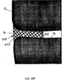
必要ならば、ステント340の1つまたはそれ以上の部分(あるいは本願明細書に記載の他の実施形態)は、例えばステント340のセルの間において非多孔性表面、部分的多孔性表面、または多孔性表面を形成するために、メンブレン、フィルム、またはコーティング(図示せず)を有するものであってもよい。例えば、択一的な実施形態に係るステント340”が図25に図示されており、これは上述の他の実施形態と同様に構成され、そして/または形成されている(同様の構成部品には同様の参照符号に”を付けて図示されている。)。ステント340”は、第1の部分342”とともに拡張するメンブレン350”を有する第1のフレア展開部342”を備えている。
If necessary, one or more portions of the stent 340 (or other embodiments described herein) can be non-porous, partially porous, or porous, eg, between cells of the
メンブレン350”は、例えばPTFE、ePTFE、シリコーン、ポリウレタン、またはポリエチレンなどの材料からなる比較的に薄い層で形成され、ステント340”に埋設され、被膜され、周囲に挟持され、あるいは担持されるものであってもよい。メンブレン350”は、第1の部分341”がフレア展開または拡張したとき、拡張できるように実質的な弾性を有するものであってもよい。択一的には、メンブレン350”は、畳み込まれるか、圧縮されて、ステント340”に対応するように開放または展開するものであってもよい。メンブレン350”は、第1の部分341”の外側表面および/または内側表面の上に配設されていてもよい。内側表面上のメンブレン350”は、移植後しばらく経ってステント340”を再操作(recross)しやすくするものであってもよい。例えば、ステント340”を患者の体内に移植した後、ガイドワイヤまたは他の器具(図示せず)を小孔から支流血管に送達し、例えば別の処置を施すことが好ましい場合がある。これは、同一の外科処置、あるいは例えば支流血管、病変部、または主流血管が後続的な処置を必要とする場合など、患者が回復した後しばらく経ったときに生じる。メンブレン350”は、ガイドワイヤまたは他の器具の先端部が、ステント340”のストラット、セル、または他の構成要素に捕らわれ、絡み合うことを防止することができる。むしろメンブレン350”は、ガイドワイヤをステント340”から支流血管内に案内できるように、実質的に平坦で、おそらくは滑らかな表面を形成するものであってもよい。
追加的または択一的に、ステント340”上のメンブレン350”は、薬剤、あるいは他の化合物または物質を担持するものであってもよい。例えば、ステント340”の外側表面上に設けたメンブレン350”は、プラーク、損傷組織、または病変部の他の患部に圧接させて、その化合物が作用して、病変部の治療または処置を促進するようにしてもよい。
Additionally or alternatively, the
随意的には、上述の任意のステントは、例えば、挿入し、配置し、そして/または拡張させるときにステントをモニタしやすくするために、1つまたはそれ以上の放射線不透過性マーカまたはその他のマーカ(図示せず)を有していてもよい。例えば、図21Aおよび図21Bを参照すると、プラチナ、イリジウム、タングステン、またはこれらの合金などの放射線不透過性材料は、ステント40の第1端342および第2端344のそれぞれに、および/または第1および第2の部分341,342の間の移行部に隣接して配設してもよい。追加的または択一的に、X線透視装置または他の外部写像装置を用いてステント340をモニタしやすくするために、放射線不透過性材料からなるワイヤ、ロッド、または他の構成要素(図示せず)をステント340上の所定位置に配置してもよい。
Optionally, any of the stents described above may include one or more radiopaque markers or other, for example, to facilitate monitoring of the stent as it is inserted, deployed, and / or expanded. You may have a marker (not shown). For example, referring to FIGS. 21A and 21B, a radiopaque material such as platinum, iridium, tungsten, or alloys thereof may be applied to each of
追加的または択一的に、ステント340(上述の実施形態に記載のステント)は、患者の体内の標的部位の治療を促進または支援する1つまたはそれ以上の治療薬または他の物質(図示せず)を担持するようにしてもよい。例えば、ステント340は、標的部位における再狭窄を阻害する化合物を担持していてもよい。
Additionally or alternatively, the stent 340 (the stent described in the above embodiments) may include one or more therapeutic agents or other substances (not shown) that facilitate or assist treatment of a target site within the patient's body. May be carried. For example, the
図26A〜図26Fを参照すると、別の例示的な実施形態に係る装置310(ただし上述の任意の実施形態に係る装置であってもよい)が図示されており、ステント340を小孔、または主流体内管腔92から支流体内管腔が延びる他の分岐点90に送達するためのものである。装置310は、概略、近位端(図示せず)、遠位端316、および近位端と遠位端316の間に延び、長手方向軸320を形成する1つまたはそれ以上のルーメン318を有するカテーテルまたは伸張管状部材312を有する。遠位端316において、1つまたはそれ以上のバルーンあるいは他の拡張可能な部品322、すなわち図示された第1の近位バルーン322aおよび第2の遠位バルーン322bが配設されている。
Referring to FIGS. 26A-26F, a
カテーテル312は、(図示しないハンドルなどの)近位端と遠位端316の間に延びる複数のルーメン318を有する。例えば、カテーテル312は、近位端から遠位先端部317に設けた開口部まで延びる器具ルーメンを有するものであってもよい。以下に説明するように、カテーテル312をレール上に沿って挿入しやすくするために、器具ルーメンはガイドワイヤまたは他のレールあるいは器具(図示せず)が内部を貫通できるような寸法を有していてもよい。随意的には、近位端(またはハンドル)は、血液などの流体が器具ルーメンから近位側に流れ出さないようにするとともに、1つまたはそれ以上の器具を器具ルーメン内に挿通できるようにするための止血シール材などの1つまたはそれ以上のシール部材(図示せず)を有していてもよい。
追加的には、カテーテル312は、近位端(またはハンドル)にある各ポートからカテーテル312内を貫通して、それぞれのバルーン322a,322bの内側と連通する開口部まで延びる膨張ルーメン(図示せず)を有していてもよい。生理食塩水を充填したシリンジなどの膨張媒体源および/または真空源をハンドルに接続して、バルーン322を拡張または収縮させることができる。
In addition, the
図26A〜図26Cに図示されているように、装置310は、当初、上記実施形態に係る任意のステント340を保持している。例えば、ステント340の第1の部分341が少なくとも部分的に近位バルーン322aを包囲し、ステント340の第2の部分343が遠位バルーン322bを包囲するように、ステント340は、カテーテル312の遠位端316の周囲に取り付けられている。随意的には、この装置310は、ステント340を包囲または被覆することができるシースまたは他のカバー(図示せず)を有していてもよい。以下に説明するように、シースは、展開前において、ステント340の近位部分341および遠位部分343あるいはステント340全体の上にあったものを移動させて、ステント340を露出させてもよい。
As shown in FIGS. 26A-26C, the
図26A〜図26Fを参照すると、上記実施形態に係る任意の装置310を用いて、ステント340を小孔90に送達するための例示的な方法が図示されている。上記説明した他の実施形態と同様、小孔90は、第2の支流体内管腔に連通する第1の主流体内管腔の壁部に設けられた開口部であってもよい。閉塞部または他の病変部96は、小孔90において、そして/または小孔に隣接して存在し、支流体内管腔94内に少なくとも部分的に延びるものであってもよい。病変部96は、動脈硬化性プラークや、血管または主流体内管腔92と支流体内管腔94の間にある他の流体通路を部分的または完全に閉塞させる物体を含み得る。
Referring to FIGS. 26A-26F, an exemplary method for delivering the
最初に、図26Aに示すように、ガイドワイヤ98または他のレールが主流体内管腔92から小孔90を通って支流体内管腔94に案内される。図示のように、小孔90における病変部96が小孔90を部分的に閉塞し、支流体内管腔の内部に延びている。ガイドワイヤ98は従来式の手法を用いて配置することができる。例えば、大腿動脈や頸動脈、他の注入部位などの末梢血管内に経皮的穿刺部位または切開部位を形成し、単独であるいはカテーテルまたはシース(図示せず)の支援を伴って、ガイドワイヤ98を注入部位から患者の脈管系を通して挿入することができる。
Initially, a
病変部96を超えて支流体内管腔94内に至るまでガイドワイヤ98を挿入した後、病変部96を少なくとも部分的に拡張させることが好ましい。例えば、バルーンまたは拡張カテーテル(図示せず)は、ガイドワイヤ98上に沿って病変部96内を通って挿入することができ、このときバルーンまたはカテーテル上の他の部材は、病変部96の少なくとも一部を押し広げるように拡張することができる。必要ならば、ステント340を移植する前に、病変部96を形成するプラークまたは他の物質を柔軟化し、除去し、あるいは処置するなどして、病変部96における他の施術を行うことができる。こうした施術を行った後に、ガイドワイヤ98上に沿って挿入された器具が引き抜かれる。
It is preferable that the
随意的には、例えばガイドカテーテルの遠位端が小孔90に隣接または近接して配置されるまで、ガイドカテーテル(図示せず)をガイドワイヤ98上に沿って主流体内管腔92内に挿入してもよい。ガイドカテーテルを用いて、1つまたはそれ以上の(上述のような)器具をガイドワイヤ98上に沿って主流体内管腔92および/または支流体内管腔94に挿入することができる。加えて、ガイドワイヤ98ととともに、ガイドワイヤ98に代わって、ガイドカテーテルが、装置310を主流体内管腔92および/または支流体内管腔94に挿入しやすくするものであってもよい。
Optionally, a guide catheter (not shown) is inserted over the
図26Bを参照すると、装置310の遠位端316が、収縮状態にあるバルーン322とともに、注入部位からガイドワイヤ98上に沿って(そして/または図示しないガイドカテーテルを貫通して)主流体内管腔92に挿入される。図26Cに示すように、遠位先端部317を小孔90に隣接させたとき、例えば生理食塩水、窒素、または他の膨張媒体を、装置310の近位端(同様に図示されない)に接続されたシリンジまたは他の流体源(図示せず)から、近位バルーン322の内部に送達することにより、近位バルーン322aを拡張させることができる。近位バルーン322aを拡張させると、ステント340の第1の部分341がフレア展開形状に拡張する。
Referring to FIG. 26B, the
択一的には、確実に、ステント340を小孔90内に十分に挿入するために、最初に、ステント340が病変部を完全に通過して支流血管94内に入るまで、ステント340およびバルーン322を収縮させた状態で装置310を挿入してもよい。その後、少なくとも近位バルーン322aが主流血管92内に配設されるまで装置310を引き抜いて、上述のように近位バルーン322aを拡張させてもよい。
Alternatively, to ensure that the
図26Dを参照すると、第1の部分341がフレア展開または拡張した状態にあり、第1の部分341が小孔90を包囲する主流体内管腔92の壁部に接触するまで、装置310を遠位方向ガイドワイヤ98上に沿って小孔90内に挿入してもよい。装置310を挿入すると、例えば、図示のように、ステント340の第2の部分343が病変部96内に配置されるまで、カテーテル312の遠位先端部317が小孔90に入り、病変部96を通過して支流体内管腔94に挿入されるようにしてもよい。随意的には、ステント340が1つまたはそれ以上の放射線不透過性マーカを有する場合、X線透視技術または他の外部写像技術を用いて、確実にステント340を小孔90および支流体内管腔94内の適正な位置に配置することができる。
Referring to FIG. 26D, the
図26Eを参照すると、第2の部分343が病変部96内に配置されており、遠位バルーン322bを拡張させることにより、病変部96における支流体内管腔94を押し広げ、あるいは裏打ちすることができる。例えば、ステント340の第2の部分343を拡張させたとき、プラークおよび/または病変部96を構成する他の物質が半径方向外側に押しやられ、病変部96の下流側にある支流体内管腔94の直径よりも大きい直径を有するように拡張させることができる。そして、ステント340および/または装置310は、1つまたはそれ以上の放射線不透過性マーカを有する場合、あるいは造影剤が主流体内管腔92および/または支流体内管腔94内に供給された場合、小孔90および/または病変部96の画像が得られ、ステント340の位置を確認し、そして/または所望の直径または断面が得られるまで、病変部96の拡張の度合いをモニタすることができる。
Referring to FIG. 26E, the
随意的には、例えばステント340の第1の部分341を小孔90に対して付勢するために、装置310に対して遠位方向にさらに力を加えてもよい。このように付勢することにより、例えば第1の部分341を小径90の形状および/または輪郭を少なくとも部分的に一致させるように、第1の部分341を可塑変形させることができる。なお、遠位バルーン322bを膨張させる前、膨張させている間、あるいは膨張させた後に、こうした追加的な付勢力を加えることができる。
Optionally, additional force may be applied distally to the
追加的または択一的に、近位バルーン322aが弾性的に拡張可能である場合、最初に、例えば近位バルーン322aを(図26Cおよび図26Dを参照して説明したように)第1の拡張状態に拡張させて、ステント340の第1の部分341を小孔90に接触または載置させてもよい。遠位バルーン322bを膨張させてステント340の第2の部分343を拡張させ、病変部を(図26Eを参照して説明したように)所望の程度に押し広げた後、近位バルーン322aをさらに拡張させて、あるいはステント340の第1の部分341を小孔90の外形形状にさらに合致させるようにしてもよい。このようにさらに拡張させることにより、ステント340をさらに確実に載置させ、そして/または固定し、そして/あるいは小孔90を押し広げることができる。
Additionally or alternatively, if the
択一的には、近位バルーン322aを拡張させる前に、遠位バルーン322bを少なくとも部分的に拡張させてもよい。さらなる択一例において、各バルーン322を拡張させる前に、ステント340を小孔90内に配置してもよい。例えばX線透視技術を用いて、ステント340上の放射線不透過性マーカ(図示せず)および/または送達装置310をモニタして、ステント340を配置しやすくしてもよい。ステント340が適正位置に配置されると、上述のように同時または順次、各バルーン322を拡張させてもよい。例えば、遠位バルーン322bは、本願明細書で説明したように、ステント340を支流体内管腔94内に固定するために拡張させてもよい。
Alternatively, the distal balloon 322b may be at least partially expanded before the
図26Fを参照すると、ステント340を所望の形態に拡張および/または配置すると、カテーテル312の近位端(図示せず)にあるシリンジまたは他のデバイス(図示せず)を用いて膨張媒体を排出することにより、各バルーン322を収縮させてもよい。バルーン322は、同時または順次に膨張させてもよく、例えば、先に遠位バルーン322bを膨張させた後、(随意的には、必要ならば、遠位方向にさらに付勢した後に)近位バルーン322aを膨張させてもよい。各バルーン322を収縮させた後、装置310を主流体内管腔92から患者の体内から抜き取る。ガイドカテーテルや他のシース(図示せず)を用いる場合、装置310を取り除く前に、ガイドカテーテルまたはシースを小孔90に対して、あるいは小孔内に挿入して、ステント340を取り出すことなく、バルーン322を抜き取り易くしてもよい。装置310よりも前に、後に、あるいは同時に、ガイドワイヤ98(および/またはガイドカテーテルまたはシース、使用した場合)を抜き取ってもよい。こうしてステント340は所定の位置に留置され、病変部96を押し広げる。
Referring to FIG. 26F, once the
本願明細書で記載したようなステント340を送達するための他の装置および方法が2006年5月23日付けで出願された米国特許出願第11/419,997号および第11/439,717号に開示されている。例えば、米国特許出願第11/419,997号には、装置310の上に、あるいは装置とともに設けられているロケータデバイスであって、送達時に、小孔の位置を特定し、そして/またはステントを配置することを支援するさまざまなロケータデバイスが開示されている。
Other devices and methods for delivering
図27A〜図27Fを参照すると、上記説明した手法と同様、ステント340を分岐点90内に送達するための別の手法が図示されている。図27Aには、カテーテル312の遠位部分316に取り付けられた収縮状態にあるステント340が図示されている。図27Bを参照すると、近位バルーン322aは、分岐点に隣接した位置に送達した後、所定寸法となるまで膨張させ、ステント340の第1の部分341を拡張および/またはフレア展開させてもよい。図示のように、第1の部分341は、過剰にフレア展開させてもよく、すなわちステント340が送達される小孔に対応する形状よりも大きな角度となるまで塑性変形またはフレア展開させてもよい。例えば、第1の部分341は、長手方向軸320に対して90度まで、あるいは90度を超える角度までフレア展開させてもよい。
Referring to FIGS. 27A-27F, another approach for delivering the
図27Cを参照すると、拡張および/またはフレア展開させた後、ステント340のフレア展開した第1の部分341が近位バルーン322aの表面から離脱するように、近位バルーン322aを部分的に収縮させてもよい。
Referring to FIG. 27C, after expansion and / or flaring, the
図27Dを参照すると、カテーテル312の遠位部分316は、本願明細書で説明したように、ガイドワイヤ(図示せず)上に沿って支流血管94内に挿入されている。過剰にフレア展開させたことにより、第1の部分41を若干小さくフレア展開させるような、すなわち小孔90の外形形状に少なくとも部分的に合致させるような十分な力で、ステント340の第1の部分341を小孔90内に挿入することができる。このように挿入する力により、第1の部分341に弾性付加を与え、小孔90に対するステント340の配置および/または固定を支援することができる。
Referring to FIG. 27D, the
図27Eを参照すると、ステント340を小孔90内に実質的に載置するように装置310が挿入されたとき、図27Fに示すように、遠位バルーン322bを膨張させて、ステント340の第2の部分343を拡張させてもよい。そしてバルーン322を収縮させて、小孔90および体内から装置310を抜き取り、ステント340を小孔90内に留置する。
Referring to FIG. 27E, when the
随意的には、図27Fを参照すると、例えば、小孔90内に挿入する際、第1の部分341がばね付勢力を保持する機能を改善するために、必要ならば、ステント340の第1および第2の部分341,343の硬度をさまざまに調整してもよい。例えば、第2の部分343をアニール(焼きなまし)処理する一方、第1の部分341を比較的に硬くして、すなわち塑性変形が生じる前に、より大きい程度で弾性変形することができるようにしてもよい。択一的には、ステント340全体をより高い硬度を有するように調整してもよい。
Optionally, referring to FIG. 27F, for example, when inserted into the
図28A〜図28Dを参照すると、主流血管92から支流血管94が延びる小孔90内に装置340を送達するためのさらに別の手法が開示されている。この実施形態では、ステント340の近位部分が拡張する前に、遠位バルーン322bの遠位部分が拡張すると、支流血管94内にステント340を実質的に繋ぎ止めるものであってもよい。最初に、図28Aに示すように、他の実施形態と同様、画像形成技術および装置上のロケータ(図示せず)などを用いて、患者の脈管系を通して、ステント340が小孔90内に延びるように装置310を挿入する。
Referring to FIGS. 28A-28D, yet another approach is disclosed for delivering the
図28Bを参照すると、遠位バルーン322bを膨張させて、ステント340の遠位部分343の拡張に対する抵抗がより小さいことに起因して、図示のように、まず遠位バルーン322bの遠位部分を膨張させることができる。ステント340の遠位部分343が拡張したとき、支流体内管腔の壁部に係合し、ステント340の移動を防止し、あるいは低減する静止摩擦力を得ることができる。図28Cに示すように、遠位バルーン322bが拡張するにつれ、ステント340の遠位部分343および遠位バルーン322bが主流体内管腔92の方に拡張して、ステント340の移動に対する静止摩擦力および抵抗力を増大させ、小孔90に対してステント340を実質的に安定させることができる。
Referring to FIG. 28B, the distal balloon 322b is inflated to cause the distal portion of the distal balloon 322b to first be inflated, as shown, due to less resistance to expansion of the
図28Dを参照すると、近位バルーン322aを膨張させて、ステント340の近位部分341を拡張およびフレア展開させることができる。矢印Aで示すように、ステント340の近位部分341の拡張は、ステント340に対して近位方向の力を与える場合がある。しかしながら拡張した遠位部分343が近位方向の移動に対抗し、ステント340が移動することなく、近位部分341を拡張させ、フレア展開させることができる。随意的には、上述の他の実施形態と同様、遠位バルーン322bおよび/または近位バルーン322aを同時または順次、さらに拡張させてもよい。
Referring to FIG. 28D, the
択一的な実施形態では、独立したバルーンまたは拡張可能部品(図示せず)を、遠位バルーン322bを遠位方向に超えた位置において装置310に取り付けてもよい。このバルーンは、上述の遠位バルーン322bと同様、装置310を固定するために、装置310およびステント340を小孔内に配置した後に膨張させてもよい。このバルーンは、ステント340を十分に拡張させるまで、膨張させた状態で維持し、装置310を引き抜く前に収縮させてもよい。
In alternative embodiments, a separate balloon or expandable component (not shown) may be attached to the
図29を参照すると、別の実施形態に係るステント440が開示され、これは、互いに対して異なる特性を有する複数の部分を有する。ステント440は、概略、上述の実施形態と同様、収縮状態から拡張状態に拡張することができる。図示の実施形態において、ステント440は、第1端442に隣接した第1の部分441と、第2の中間部分443と、第2端444に隣接した第3の部分445とを有する。第1の部分441は、上述の他の実施形態と同様、拡張またはフレア展開するように構成された1つまたはそれ以上のバンドセルを有するものであってもよい。すなわち第1の部分441は、主流体内管腔(図示せず)に直近の小孔(図示せず)内に送達されるように構成されたものであってもよい。例えば、以下に説明するように、ステント440を小孔内に送達した後に小孔の弾性的萎縮に対抗するために、第1の部分441は、第2および第3の部分443,445に比して相対的に硬いものであってもよい。
Referring to FIG. 29, a
例えば支流体内管腔(図示せず)が主流体内管腔から横方向に垂直方向ではなく、横方向に延びる場合、第2の中間部分443は、例えば可撓性移行部を提供するために、第1の部分441および第3の部分445に比して比較的にフレキシブルであってもよい。すなわち中間部分443は、第1の部分441および第3の部分445の間のステント440の折曲部を構成し、ステント440を貫通するルーメンがねじれたり、重大なダメージを受けるリスクを実質的に排除する。追加的には、第2の部分443は、これが支流管腔内に実質的には延びないように、第3の部分445に比して相当に短いものであってもよい。第2の部分443は、例えば、図4A〜図6Eを参照して図示および説明したものと同様に、複数のリンクまたは可撓性コネクタ(図示せず)を有するものであってもよい。択一的には、上述の例示的なセル構造体と同様に、第2の部分443は、比較的に薄いか、あるいは可撓性のある部材を有する1つまたはそれ以上のバンドセル(図示せず)を有していてもよい。
For example, if a branch fluid lumen (not shown) extends laterally from the main fluid lumen rather than laterally perpendicularly, the second intermediate portion 443 can be provided, for example, to provide a flexible transition. The
第3の部分445は、第1の部分441および第2の部分443より比較的長いものであってもよい。上述の他の実施形態と同様に、第3の部分445が支流体内管腔を補強するフープ(たが)として必要な強度を有するとともに、送達を支援するような十分な可撓性を兼ね備えるように、第3の部分の機械的な特性を調整してもよい。
The
図31および図32を参照すると、主流体内管腔92および支流体内管腔94の間で連通する小孔90を有する例示的な分岐点が図示されている。本願明細書で説明したように、小孔90および/または支流体内管腔94は、小孔90を少なくとも部分的に閉塞するプラークまたは他の狭窄物質(図示せず)を有する。このような小孔90内で展開するステントとしての必要な特性は、上述のように、長さ方向に沿って変化するものであってもよい。対称的に、分岐しない体内管腔に送達されるステントは、一般に、長さ方向に沿って実質的に均一な特性を有するものであってもよい。分岐点に送達されることが意図されたステントにおいては、こうした均一性は概して好ましいものではない。
Referring to FIGS. 31 and 32, an exemplary bifurcation having a
例えば、図31に示すように、分岐点における壁厚は、主流体内管腔92と支流体内管腔94の間で異なる場合がある。図示のように、主流体内管腔92の壁厚は支流体内管腔94より実質的に厚い場合がある。すなわち、小孔90が拡張した場合であっても、壁部の厚みが大きいほど、萎縮のリスクが大きくなり、すなわち膨張後、小孔90の壁部が付勢されて再び収縮することがある。図32は、この問題に対して望ましいステントの特性を図示したグラフを示すものである。例えば、ライン「R」は、分岐点において血管壁が有する弾性的萎縮を示すものである。図示のように萎縮は、少なくとも部分的には、壁厚のより大きい主流体内管腔92により近いところで生じる。弾性的な萎縮により、小孔90が縮減し、小孔90から離れた位置にある支流体内管腔94における萎縮は、小孔90における萎縮よりも実質的に小さく、実質的に均一なものとなる。
For example, as shown in FIG. 31, the wall thickness at the branch point may differ between the main fluid
こうした萎縮を解消するために、ライン「S」は、ステントに求められる長さ方向に沿った管腔支持力を示すものである。すなわち、主流体内管腔92に直近のステントの第1端において拡張したとき、より大きな管腔支持力または剛性を有し、小孔90から離れたところの支流体内管腔94内においてはより小さい実質的に均一の剛性を有することが好ましい。換言すると、ライン「F」は、ステントに対して要求される長さ方向に沿ったフレキシビリティ(可撓性)を示すものである。
In order to eliminate such atrophy, the line “S” indicates the lumen supporting force along the length direction required for the stent. That is, when expanded at the first end of the stent proximate to the
図30および図33〜図36は、さまざまな実施形態に係るセルパターンを図示し、それぞれのパターンを有するステントは長さ方向に沿ってさまざまな機械的特性を有する。例えば、図30は、4つの異なるバンドセルを含むステント構造体の実施形態を図示するものである。図示のように、コラム1およびコラム2は、コラム3およびコラム4より短い周期のジグザグパターンを有する。上記とは異なり、コラム1およびコラム2は、コラム3およびコラム4より数多くの軸方向部材および湾曲部材をステントの周りに配設されている。こうした差異により、コラム1およびコラム2のバンドセルは、コラム3およびコラム4より大きな管腔支持力、および/またはより少ない可撓性を有する。
30 and 33-36 illustrate cell patterns according to various embodiments, and a stent having each pattern has various mechanical properties along its length. For example, FIG. 30 illustrates an embodiment of a stent structure that includes four different band cells. As shown,
追加的に、コラム1とコラム2は、隣接する1つおきの湾曲部材の間に延びる比較的に短い軸方向リンクを用いて互いに連結されている。これらの連結部は、コラム1およびコラム2の支持力を増大し、そして/または可撓性を低減する。対称的に、コラム2とコラム3、およびコラム3とコラム4は、より長い対角線リンクを介して間欠的に連結されている。これらの連結部は、これらのコラムにおいて可撓性を増大させるものである。
Additionally,
図33を参照すると、別の実施形態に係るステント構造体が図示され、その長さ方向に沿って配置された複数のバンドセルを有するものである。この実施形態において、軸方向部材および湾曲部材は、各コラムにおいて同等の長さとスペースを有するセルを定義する。ただし、
軸方向部材および湾曲部材および/またはリンクの幅と厚みは、ステントの長さに沿って異なる。図示のように、軸方向部材および湾曲部材およびリンクの厚みは、コラム1からコラム9に至り小さくなっている。こうしてコラム1からコラム9まで、体内管腔の支持力を効率的に低減するとともに、可撓性を増大させている。
Referring to FIG. 33, a stent structure according to another embodiment is illustrated, having a plurality of band cells arranged along its length. In this embodiment, the axial member and the curved member define cells having equal length and space in each column. However,
The width and thickness of the axial and curved members and / or links vary along the length of the stent. As illustrated, the thickness of the axial member, the bending member, and the link is reduced from the
図34を参照すると、別の実施形態に係るステント構造体が図示され、その長さ方向に沿ってさまざまな特性を有するものである。この実施形態において、コラム9における軸方向部材は、コラム1における軸方向部材より長い。この構成により、コラム1からコラム9に向かって、管腔支持力が低減し、そして/または可撓性が増大することになる。追加的に、図33で示す実施形態と同様、軸方向部材および湾曲部材ならびにリンクの厚みを、コラム1からコラム9に向かって小さくなるようにしてもよい。
Referring to FIG. 34, a stent structure according to another embodiment is illustrated having various properties along its length. In this embodiment, the axial member in
図35を参照すると、さらに別の実施形態に係るステント構造体が図示され、その長さ方向に沿ってさまざまな部材を有するものである。図示のように、コラム1およびコラム2は、隣接する1つおきの湾曲部材を連結する複数のリンクを有する。コラム9に向かって連続するバンドセルは、コラム9に向かって可撓性を漸進的に増大させる間欠リンクを有する。例えば、コラム3およびコラム4に隣接するバンドセルにおいては4つおきに1つのリンクが欠落しており、コラム5に隣接するバンドセルにおいては5つおきに1つのリンクが欠落しており、コラム6〜9に隣接するバンドセルにおいては1つおきにリンクが欠落している。
Referring to FIG. 35, a stent structure according to yet another embodiment is illustrated having various members along its length. As illustrated, the
図36を参照すると、さらに別の実施形態に係るステント構造体が図示され、コラム1〜9における隣接するバンドセルの間に異なるリンクを有するものである。図示のように、コラム1とコラム2の間にはリンクが形成されず、代わりに隣接する湾曲部材同士が互いに直接連結されており、比較的に強い管腔支持力と低減された可撓性を提供するものである。コラム4〜コラム6は漸進的により長くした軸方向部材を有するのに対し、コラム7〜コラム9は可撓性を増大させる湾曲したリンクを有する。コラム7とコラム8の間のリンクは若干湾曲して、鈍角を形成するのに対し、コラム9のリンクはより大きく湾曲し、90度近い角度を形成している。例えばシヌソイド形状などのより複雑な幾何学的形状を有する択一的な実施形態に係る湾曲リンクが図36A〜図36Cに図示されている。これらの実施形態において、異なる形状が図示されているが、上述のような、例えば小孔内に送達されるステントの長さに沿った所望する多様性を実現するために、これらの特徴および形状をさまざまに組み合わせられることを理解されたい。
Referring to FIG. 36, a stent structure according to yet another embodiment is illustrated having different links between adjacent band cells in columns 1-9. As shown in the figure, no link is formed between the
図37を参照すると、別の実施形態に係るフレア展開ステント540が図示されており、これは、概略、別の実施形態と同様に構成されている。上記実施形態とは異なり、図38Aに示すように、ステント540は、長さが比較的に短く、支流管腔94内に実質的に延びることなく、小孔90内においてフレア展開するようなものであってもよい。例えば、ステント540は、近位部分またはフレア展開部541と、可撓性連結部および/または可撓性中間部分(図示せず)を介して連結された遠位部分または略直線部分543とを有する。遠位部分543は、近位部分541と同等またはより短い長さを有していてもよいし、近位部分541より長くてもよいが、近位部分541の長さの2倍または3倍より短くてもよい。
Referring to FIG. 37, a flare
図38Bに示すように、先の実施形態とは異なり、独立したステント550は、支流管腔94がその遠位部分543を超えるか、あるいは重畳するように支流管腔94内に送達される。この追加的なステントは、従来式の均一な特性を有するステント、あるいは上述のステントの遠位部分と同様に、特性の調整可能なステントであってもよい。図39A〜図39Cは別の変形例を示し、図37のステント540が支流管腔94内に送達されるとともに、第1の独立したステント550が支流管腔内に送達され、例えば図38Bに示すように、第2の独立したステント560が主流管腔92内に送達されるようにしてもよい。
As shown in FIG. 38B, unlike the previous embodiment, an
図40は、例示的な実施形態に係る送達装置510を示し、これは、図37のステント540または他の同様のステントを単体で、あるいは図38Bに示すステント550などの別個の支流管腔ステントとともに送達するために用いられるものである。装置510は、前掲の特許出願に記載されたようなロケータデバイス520を有する。追加的に、装置510は、互いに対して個別に膨張させて、上述の他の実施形態と同様にステント540を拡張させる1つまたはそれ以上のバルーンを有し、例えばより大きな近位バルーン522aと、より小さな遠位バルーン522bとを有する。例えば、ステント540の近位フレア展開部541は、近位バルーン522aの上を少なくとも部分的に重畳し、遠位部分543は遠位バルーン522bの上を重畳する。
FIG. 40 illustrates a
図41〜図43を参照すると、さらに別の実施形態に係る送達装置610が図示され、これは、小孔または主流管腔と支流管腔(図示せず)の間にある他の分岐点に、ステントまたは他のプロテーゼ640を送達するためのものである。装置610は、概略、送達カテーテルまたは他の伸張管状部材612を有し、送達カテーテルは、近位端614と、遠位端616と、近位端614および遠位端616の間に延びる1つまたはそれ以上のルーメン618とを有し、近位端614および遠位端616の間に延びる長手方向軸を形成するものである。
With reference to FIGS. 41-43, a
図示のように、本願明細書で記載された他の実施形態と同様、送達カテーテル612は、ステント640を拡張および/またはフレア展開させるための1つまたはそれ以上のバルーンまたは拡張可能部品622を遠位端16において有する。追加的には、遠位端616は、送達カテーテル612および/またはステント640の配置を支援するための、1つまたはそれ以上の(図41では2つの)放射線不透過性マーカ619などの1つまたはそれ以上のマーカを有していてもよい。追加的または択一的には、送達カテーテル612は、ステント640および/またはバルーン622の代わりに、あるいはこれに加えて、1つまたはそれ以上の治療要素および/または診断要素を有していてもよい。
As shown, similar to the other embodiments described herein, the
随意的には、2003年11月12日付けで出願された米国特許出願第10/712,888号、2005年9月29日付けで出願された米国特許出願第60/722,182号、および米国特許出願第11/419,997号で開示されたように、送達カテーテル612は、遠位端616において、すなわちステント640に近接して、あるいはステント640に隣接して設けた1つまたはそれ以上のロケータ要素(図示せず)を有していてもよい。
Optionally, U.S. Patent Application No. 10 / 712,888, filed November 12, 2003, U.S. Patent Application No. 60 / 722,182, filed Sep. 29, 2005, and U.S. Patent Application No. As disclosed in US Ser. No. 11 / 419,997, the
ステント640は、第1の部分またはフレア展開部642と、第2の管状部分644とを有する。図示のように、第1の部分642は、例えば順行送達のために、第2の部分644の近位側に配設されている。択一的には、上述の他の実施形態と同様、退行送達のために、第1および第2の部分642,644を逆にしてもよい。この択一例では、送達カテーテル612(または上述の他の送達デバイス)の遠位端616上のバルーン622の向きは、上記のものとは反対であってもよい。
ステント640は、例えば、上記の他の実施形態と同様、塑性変形して拡張可能なさまざまな材料で形成することができる。択一的には、ステント640の少なくとも一部が自己拡張し、そして/または拡張に対するステント640の抵抗力は、同様に上記の他の実施形態のように、長さ方向に沿って変化するものであってもよい。
The
ステント640は、通常、管状構造体であり、例えば、ステント640の拡張を支援し、そして/または組織の内部成長を可能にする開口部を含む管状壁部を有するものであってもよい。ステント640は、例えば、レーザ切断、機械切断、化学エッチング、マシーン加工などにより管状壁部に設けたスロットまたは他の開口部を有する伸張チューブであってもよい。択一的には、ステント640は、編み込んだものであってもよいし、1つまたはそれ以上のワイヤまたは他のフィラメントあるいは所望の手法により捲回して形成される他の構造体であってもよい。さらなる実現可能なステント構造体は螺旋状コイルワイヤまたはシート、溶接または固定ワイヤ、あるいは他の構造体などであってもよい。必要ならば、上述の他の実施形態と同様、ステント640の1つまたはそれ以上の部分は、例えばステント640のセルの間において非多孔性表面、部分的多孔性表面、または多孔性表面を形成するために、そして/あるいは1つまたはそれ以上の薬剤成分を担持するために、メンブレン、フィルム、またはコーティング(図示せず)を有するものであってもよい。
The
追加的には、図42および図43に示すように、装置610は、近位端662と、遠位端664と、これらの間に延びるルーメン666とを有するガイドカテーテル660を備える。以下に説明するように、遠位端664は患者の脈管系または他の体内管腔内に挿入しやすい寸法および形状を有する。ルーメン666は、挿通される送達カテーテル612の遠位端616、例えば収縮された状態にあるロケータ部材(図示せず)を受容できる程度に十分な寸法を有する。随意的には、ガイドカテーテル660の遠位端664は、J字形状などの予め設定された形状に付勢され、ガイドカテーテル660を小孔内にまたは小孔に隣接して配置しやすくことができる。ガイドカテーテル660のねじれや歪みを防ぐように十分に支持するとともに、ガイドカテーテル660が複雑な生体構造の中を容易に挿入することができるように、ガイドカテーテル660は、例えばブレイド(braid)または他の補強材(図示せず)を有するプラスティックなどの実質的に可撓性および/または柔軟性を有する材質で形成される。
Additionally, as shown in FIGS. 42 and 43, the
随意的には、装置610は、ステント640を送達するためのシステムまたはキットを構成する他の構成部品を有するものであってもよく、例えば、送達カテーテル612の遠位端616上に挿入し、そして/または引き抜くためのシースや、他にもシリンジまたは1つまたはそれ以上の膨張媒体ソースおよび/または真空ソース、チューブ、および/または1つまたはそれ以上のガイドワイヤ(すべて図示せず)などを備えていてもよい。
Optionally,
図41〜図43に戻ると、送達カテーテル612は、例えば長さ方向に沿って異なる可撓性を有する1つまたはそれ以上の管状本体部で構成してもよい。例えば、他の実施形態と同様、遠位端616は、複雑な生体構造内に挿入しやすくするために、実質的な可撓性を有し、丸く、傾斜し、そして/または他の実質的に生体を傷つけないような遠位端617であってもよい。遠位端616は、体内管腔内に案内できるような寸法および/または形状を有し、例えば約1mm〜7mmの直径、あるいは1.5mm未満の直径を有する。近位端614は、実質的な可撓性または半剛性を有し、近位端614を押すことにより、遠位端617を患者の脈管系内に挿通しやすくするのに十分なコラム強度を有する。随意的には、図41に示すように、シャフト支持ワイヤまたは他の補強材615を近位端614内に設けて、送達カテーテル612を近位端614から押し込みやすくしてもよい。送達カテーテル612は、プラスティック、金属、または複合材料であってもよく、例えば挿入時における送達カテーテル612のねじれや歪みを防ぐワイヤ、ブレイド、コイルコアなどを含むプラスティック材料であってもよい。
Returning to FIGS. 41-43, the
図示のように、送達カテーテル612は、上述の他の実施形態にも含まれるものであるが、近位端614において、例えば送達カテーテル612の操作を支援するためのハンドル630を有する。ハンドル630は、送達カテーテル612内のルーメン618のそれぞれと連通する1つまたはそれ以上のポート632を有する。ハンドル630は、プラスティック、金属、または複合材料を用いて、モールド成形、マシーン加工、または他の手法により形成され、操作しやすい形状に構成または加工された外側ケースを有するものであってもよい。送達カテーテル612の近位端614は、例えば接着剤、協同コネクタ、界面嵌合などによりハンドル630に固定される。随意的には、装置610が任意の作動可能部品(図示せず)を有する場合、ハンドル630は、例えば1つまたはそれ以上のスライド、ダイヤル、ボタンなどの1つまたはそれ以上のアクチュエータを有し、近位端614からこうした作動可能部品を作動させ、あるいは操作する。
As shown, the
図41に最も明確に図示されているように、カテーテル612は、近位端614および遠位端616の間に延びる少なくとも3つのルーメン618を有する。例えば、カテーテル612は、側部ポート632aから遠位先端部617にある開口部634まで延びる器具ルーメン618aを有する。以下に説明するように、器具ルーメン618aは、ガイドワイヤまたは他のレールあるいは器具(図示せず)を挿通して、カテーテル612をレール上に挿入することができるような十分な大きさを有する。択一的には、「迅速交換」器具ルーメン618aの代わりに、遠位端616からハンドル630まで延びる器具ルーメン(図示せず)を設けてもよい。この択一例では、ハンドル630は、ポート(図示せず)および/または1つまたはそれ以上のシール部材(図示せず)を有し、このシール材により、血液などの流体がポートから近位側に流出することを防止するとともに、器具ルーメン618a内に1つまたはそれ以上の器具を器具ルーメン618a内に挿通することができる。
As most clearly illustrated in FIG. 41, the
追加的には、カテーテル612は、ハンドル630の各側部ポート632b,632cからカテーテル612を介して遠位端616にある開口部634b,634cにそれぞれ延びる膨張ルーメン618b,618cを有する。各開口部634b,634cは、それぞれのバルーン622a,622bの内部と連通する。ハンドル630の各側部ポート632b,632cは、ルアロックコネクタ(図示せず)、1つまたはそれ以上のシール部材などの接続部(図示せず)を有する。バルーン622a,622bを膨張および/または収縮させるために、生理食塩水(図示せず)を充填したシリンジなどの膨張媒体ソースおよび/または真空ソースを、チューブ(図示せず)を介して側部ポート632b,632cに接続してもよい。
Additionally, the
図41に示すように、各ルーメン618は互いに隣接している。択一的には、各ルーメン618はカテーテル612の本体部内で同心配置または他の配置を有していてもよい。さらに装置610が遠位端616において追加的なバルーン(図示せず)を有する場合、図41を参照して図示および説明したものと同様、カテーテル612は1つまたはそれ以上の追加的な膨張ルーメン(図示せず)を有し、ハンドル630は1つまたはそれ以上のポート(図示せず)を有していてもよい。
As shown in FIG. 41, the
択一的には、他の形態を有するルーメンを用いて、一方または両方のバルーン622に流体を送達し、そして/または一方または両方のバルーン622から流体を吸引してもよい。例えば、両方のバルーン622の内部623と連通する単一のルーメン(図示せず)を用いてもよい。この実施形態によれば、単一のシリンジまたは他の流体/真空ソースを用いて、実質的に同時にバルーン622を拡張および/または収縮させることができる。別の択一例では、カテーテル612は、個別の膨張ルーメン618b,618cを有するが、ハンドル630は、シリンジまたは他の流体/真空ソースが接続され得る単一の側部ポート(図示せず)を有する。この択一例では、ハンドル630は、膨張ルーメン618b,618cの一方または両方を側部ポートに選択的に接続するためのスイッチ、止栓、バルブ、または他のデバイスを有していてもよい。
Alternatively, lumens having other configurations may be used to deliver fluid to one or both balloons 622 and / or to aspirate fluid from one or both balloons 622. For example, a single lumen (not shown) that communicates with the interior 623 of both balloons 622 may be used. According to this embodiment, a single syringe or other fluid / vacuum source can be used to expand and / or deflate the balloon 622 substantially simultaneously. In another alternative, the
例えば、三方弁(図示せず)を第1または第2の位置に配置して、バルーン622a,622bを独立して収縮/膨張させるために、側部ポートを膨張ルーメン618b,618cのいずれか一方に接続してもよい。第3の位置において、側部ポートを両方のルーメン618b,618cに接続して、両方のバルーン622を同時に膨張/収縮させてもよい。この形態は、ステント640を移植した後、装置610を引き抜く前に、両方のバルーン622を速やかに収縮させる上でとりわけ有用である。さらにこの形態は、例えば第1の部分642を拡張させ、固定した後、そして/または第2の部分644をフレア展開させた後に、ステント全体の拡張を支援することができる。
For example, a side port can be placed on one of the inflation lumens 618b, 618c to place a three-way valve (not shown) in the first or second position to independently deflate / inflate the
図41〜図43に戻ると、送達カテーテル612は、遠位先端部616において、外側バルーンまたは近位バルーン622aと、内側バルーンまたは遠位バルーン622bとを有する。図示のように、ステント640の第1の部分642は近位バルーン622aの一部分の上に配置され、ステント640の第2の部分644は遠位バルーン622bの少なくとも一部分の上に配置されている。択一的には、送達カテーテル612は、遠位端616において、単一または複数のバルーン(図示せず)を有し、その上方にステント640が配置されている。
Returning to FIGS. 41-43, the
バルーン622は、送達カテーテル612の遠位端16に接着または固定してもよい。例えば、接着剤、超音波溶接、または環状カラーまたはスリーブを用いるなどして、バルーン622の端部を遠位端16に取り付けてもよい。遠位バルーン622bは、開口部634cに隣接するカテーテル612の遠位端616に固定された近位端624aと、遠位先端部617に隣接して固定された遠位端626aとを有する。近位バルーン622aは、遠位バルーン622bの少なくとも一部分の上に延びている。例えば、近位バルーン622aの遠位端は、上述のように、接着剤または超音波溶接などを用いて、遠位バルーン622bの上方全体にわたって延び、遠位バルーン622bの遠位端上または遠位端に隣接して固定してもよい。
Balloon 622 may be glued or secured to the
遠位バルーン622bは、(図42で示す)収縮状態から(図41で示す)拡大状態に拡張させることができる。同様に、近位バルーン622aは、(図42で示す)収縮状態から(図41および図43で示す)拡大状態に拡張させることができる。図示のように、近位バルーン622aおよび遠位バルーン622bは、互いに独立して拡張させることができる。
The
特に図41を参照すると、拡張状態にあるとき、近位バルーン622aは、近位傾斜表面628aおよび遠位傾斜表面628bを有し、これらの傾斜表面は最外部にある中間領域628bで連続する。図示のように、中間領域628bは、例えば第1の部分642をフレア展開させるために、ステント640の第1の部分640の真下に延びるようにステント640に隣接して配置され、例えばステント640の配置を支援するために、第1の部分642より近位側に配置してもよい。
With particular reference to FIG. 41, when in the expanded state, the proximal balloon 622a has a proximal inclined surface 628a and a distal inclined surface 628b that are continuous with the outermost intermediate region 628b. As shown, the intermediate region 628b is disposed adjacent to the
各バルーン622は、十分な流体が内部に導入されると、所定の大きさを有する拡張状態に拡張するように、PET、ナイロン、またはPEBAXなどの非弾性材料を用いて形成してもよい。択一的には、各バルーン622は、内部に導入される流体の容量および圧力に依存して、さまざまな寸法に拡張できるように、シリコーン、ポリウレタン、またはポリエチレンなどの弾性材料を用いて形成してもよい。 Each balloon 622 may be formed using a non-elastic material such as PET, nylon, or PEBAX so that when sufficient fluid is introduced therein, it expands into an expanded state having a predetermined size. Alternatively, each balloon 622 is formed using an elastic material such as silicone, polyurethane, or polyethylene so that it can expand to various dimensions depending on the volume and pressure of the fluid introduced therein. May be.
随意的には、送達カテーテル612は、ステント640の第2の部分644に隣接して配置された係止部650を有していてもよい。係止部650は、図示のように各バルーン622の一部の上方に形成され、固定され、取り付けられた管状部材の一部分であってもよい。係止部650は、ステント640に隣接した実質的に先が尖っていない近位端652を有し、この近位端はステント640の第2の部分644に接触しており、以下に説明するように、ステント640の第1の部分を膨張させたとき、ステント640が遠位方向に移動することを防止するためのものである。追加的または択一的には、スリーブ(図示せず)は、例えばステント640の遠位端644を部分的にカバーし、遠位端644が係止部650の上から離脱/脱落することを防止するように、係止部650から延び流ようにしてもよい。択一的には、米国特許第136,266号に開示されたスリーブディスクなどのように、ステント40の遠位方向の移動を拘束し、固定し、制限するための他の構造体(図示せず)を配設してもよい。
Optionally, the
図44〜図48を参照すると、ステント640を小孔90内に送達するための(本願明細書で説明した任意の実施形態に係る)装置610を用いる例示的な手法が図示されている。本願明細書の他の段落で記載されているように、小孔90は第1または主流体内管腔または幹流の壁部に開口部を有するものであり、第1の体内管腔は第2の体内管腔または支流94に連通する。閉塞部または他の病変部は、小孔90において、あるいは小孔に隣接して形成され、少なくとも部分的に支流管腔94内に延びることがある。病変部96は、幹流92と支流94の間の血管または他の流体フロー部分的または完全に閉塞する動脈硬化性プラークあるいは他の物質である。
With reference to FIGS. 44-48, an exemplary approach using a device 610 (in accordance with any embodiment described herein) for delivering a
図44に示すように、まずガイドワイヤ98または他のレールが幹流92から小孔90を通って支流94内に案内される。図示のように、小孔90における病変部96は、小孔90を閉塞させるものであり、支流内に延びている。ガイドワイヤ98は、従来式の手法を用いて配置される。例えば、大腿動脈、頸動脈または他の侵入部位などの末梢領域(図示せず)において経皮穿刺傷または切開傷を形成して、ガイドワイヤ98は、単体またはガイドカテーテル660の支援を受けて、侵入部位から患者の脈管系を介して挿入してもよい。病変部96が支流94を完全に閉塞する場合、ガイドワイヤ98が閉塞部を貫通するように案内され、または他のデバイス(図示せず)がガイドワイヤ98上に沿って、あるいはガイドワイヤ98と協同して挿入され、病変部96を貫通するガイドワイヤ98のための通路を形成してもよい。
As shown in FIG. 44, a
ガイドワイヤ98が病変部96を超えて支流94内に案内された後、病変部96を少なくとも部分的に押し広げることが好ましい。例えば、血管形成用カテーテル(図示せず)をガイドカテーテル660により、そして/またはガイドワイヤ98の上方に沿って病変部96内およびこれを貫通するように挿入してもよい。このとき、カテーテル上のバルーンまたは他の構成部品は拡張して、少なくとも部分的に病変部96を押し広げることができる。必要ならば、ステント640を留置する前に、プラークまたは病変部96形成する他の物質を柔軟化し、除去し、あるいは処置するなどして、病変部96において他の施術を行ってもよい。こうした処置がすべて完了した後、ガイドワイヤ98の上方に沿って挿入された器具はすべて引き抜かれる。
After the
図44に示すように、ガイドカテーテル660の遠位端664は、例えば小孔90に隣接または近接するまで、ガイドワイヤ98の上方に沿って幹流92内に挿入される。ガイドカテーテル660を用いて(上述したような)1つまたはそれ以上の器具をガイドワイヤ98の上方に沿って幹流92および/または支流94内に挿入してもよい。
As shown in FIG. 44, the
図45を参照すると、ステント640を送達するためには、送達カテーテル612の遠位端616をガイドワイヤ98の上方に沿って、そしてガイドカテーテル660のルーメン666内を通って、侵入部位から幹流92内に挿入される。図示のように、ステント640およびバルーン622は、挿入時においては収縮状態にある。ガイドカテーテル660の遠位端664が小孔90に当接または隣接したとき、送達カテーテル612の遠位端616は、ガイドカテーテル660から小孔90を通って支流90内に挿入される。例えば図46に示すように、ステント640の各部分を拡張させる前に、ステント640が病変部96を超えて内側にまで延び、確実に、ステント640を病変部96内に完全に配置するまで、送達カテーテル612は挿入される。
45, to deliver the
図47を参照すると、ステント640が病変部96内に配置され、ステント640の第1の部分642が支流94内の小孔90に隣接配置されるように、送達カテーテル612は部分的に引き出される(あるいは配置される)。このような配置を支援するために、X線透視技術または他の外部写像技術を用いて、遠位端616上に設けたマーカ619(図示せず、図41参照)を観測およびモニタするなどして、送達カテーテル612をモニタしてもよい。追加的には、必要ならば、ガイドカテーテル660が送達カテーテル612の遠位端616の動作の障害にならないように、ガイドカテーテル660を幹流92内に部分的に引き出してもよい。
47, the
図48を参照すると、送達カテーテル612およびステント640が適正位置に配置され、このとき送達カテーテル612の近位端(図示せず)に接続されたシリンジまたは他の流体源(図示せず)から、例えば生理食塩水、窒素、または他の膨張媒体を近位バルーン622aの内部623(図示せず、図41参照)に供給することにより、近位バルーン322aを拡張させることができる。近位バルーン622aを拡張させると、ステント640の第1の部分642がフレア展開形状に拡張し、近位バルーン622aの遠位表面628cの形状と一致する。
48, from a syringe or other fluid source (not shown) connected to the proximal end (not shown) of
図49に示すように、近位バルーン622aを拡張させると、ステント640を超えた近位バルーン622aの遠位表面628cが小孔90に隣接する支流に接触する。遠位表面628cが傾斜または勾配を有する形状を有するので、近位バルーン622aの半径方向の拡張が近位方向の力に変換され、送達カテーテルの遠位端616ひいてはステント640を近位方向に移動させることがある。上記とは異なり、近位バルーン622aを拡張させたとき、第1の部分642が小孔90の内部に配置されるように、ステント640を支流94から部分的に移動させることがある。すなわち、(X線透視技術を用いてモニタしたにもかかわらず)ステント640が必要以上に支流94の内部に遠位側に配置された場合であっても、近位バルーン622aが小孔90内におけるステント640の位置を矯正することができる。随意的には、近位バルーン622aの少なくとも遠位表面628cは滑らかな材料で形成され、そして/または滑らかなコーティングを有し、遠位表面628cと支流94の壁部との間の摩擦を低減して、ステント640の移動および/または自動的な位置矯正を支援するようにしてもよい。
As shown in FIG. 49, when the proximal balloon 622a is expanded, the
図50を参照すると、近位バルーン622aを膨張させた後、遠位バルーン622bを膨張させて、ステントを完全に拡張させる。図41に示すように、配設された遠位バルーン622bを近位バルーン622aの内側に配置したとき、遠位バルーン622bが近位バルーン622a、ひいてはステント640の第1の部分642をさらに拡張させる。すなわち、遠位バルーン622bは、支流94内にあるステント640の第2の部分644を拡張させるとともに、近位バルーン622aがステント640の第1の部分642を拡張またはフレア展開させて、小孔90の壁部に接触させることを支援することができる。追加的または択一的に、第1の部分642が小孔90に接触して、そして/または押し広げるように、近位バルーン622aをさらに膨張させて、ステント640の第1の部分642をさらに拡張またはフレア展開させることができる。ステント640を拡張させると、病変部96は半径方向外側に付勢され、小孔90および/または支流94を押し広げることができる。随意的には、必要ならば、ステント640の第1の部分642を小孔90に付勢するために、すなわち、ステント640を固定すること、および/またはステント640の第1の部分642の形状を小孔90の形状に一致させることを支援するために、遠位方向の力を送達カテーテル612に加えてもよい。
Referring to FIG. 50, after inflating the proximal balloon 622a, the
図51を参照すると、ステント640を完全に展開させると、各バルーン622を収縮または萎ませて、送達カテーテル612はガイドカテーテル660を通して引き抜くことができる。随意的には、送達カテーテル612を引き抜く前に、ガイドカテーテル660を小孔90に向かって、あるいは小孔90に対して挿入し、そして/またはステント640の近位端に対して挿入してもよい。この操作は、ステント640が小孔90および/または支流94から脱落するリスクを実質的に排除しつつ、遠位端616(および各バルーン622)を、ステント640を通って引き戻しやすくすることができる。こうして、ステント640を所定位置に留置して、送達カテーテル612、ガイドカテーテル660、および/またはガイドワイヤ98を患者の体内から取り出すことができる。
Referring to FIG. 51, when the
本願明細書で開示されたすべての実施形態に係る構成部品または構成要素は、特定の実施形態に関して例示的なものであり、他の実施形態との組み合わせにおいて利用し得ることが理解されよう。 It will be understood that components or components according to all embodiments disclosed herein are exemplary with respect to a particular embodiment and may be utilized in combination with other embodiments.
本願発明は、さまざまな変形例および択一例に適用可能であるところ、特定の実施例について図面に示し、詳細に説明してきた。しかしながら、本願発明は、こうした特定の形態または手法に限定されるものではなく、添付クレームの範疇に入るすべての変形例、均等物、択一例をカバーするものであると理解すべきである。 While the invention is applicable to various modifications and alternatives, specific embodiments have been shown in the drawings and have been described in detail. However, it should be understood that the present invention is not limited to such specific forms or techniques but covers all modifications, equivalents, and alternatives falling within the scope of the appended claims.
Claims (19)
管状部材は、第1端および第2端を有し、これらの間に長手方向軸を形成し、第1端と第2端の間に配設された複数のセルを有し、収縮状態から中間状態を経て拡張状態に拡張可能であり、
このステントは、収縮状態から拡張状態に拡張するとき、外側にフレア展開する第1の端部部品と、第1の端部部品に隣接し、複数の連結部を介して第1の端部部品に連結された第2の端部部品とを有し、
第1の端部部品は、曲がりくねったパターンを有する軸方向部材および湾曲部材を含む第1および第2のバンドを有し、
第1および第2のバンドは、収縮状態から中間状態に拡張するとき、第1のバンドの第1の軸方向部材が長手方向軸とほぼ平行な方向からほぼ半径方向外側に向き、かつ、拡張状態にさらに拡張するとき、第1の軸方向部材がほぼ周囲方向に向き、第2のバンドの第2の軸方向部材がほぼ横方向に向くように連結され、
連結部は、第1の端部部品が外側にフレア展開できるように、第1の端部部品の軸方向部材および湾曲部材に比して比較的に高い可撓性を有することを特徴とするステント。A stent comprising a tubular member,
The tubular member has a first end and a second end, defines a longitudinal axis therebetween, and has a plurality of cells disposed between the first end and the second end, and from a contracted state It can be expanded to an expanded state via an intermediate state,
When the stent is expanded from the contracted state to the expanded state, the first end part is configured to flare outwardly, and the first end part is adjacent to the first end part via a plurality of connecting parts. A second end piece coupled to the
The first end piece has first and second bands including an axial member and a curved member having a tortuous pattern;
When the first and second bands expand from a contracted state to an intermediate state, the first axial member of the first band is oriented generally radially outward from a direction substantially parallel to the longitudinal axis and expanded When further expanded to the state, the first axial member is connected in a substantially circumferential direction and the second axial member of the second band is connected in a substantially lateral direction,
The connecting portion has a relatively high flexibility as compared with the axial member and the bending member of the first end part so that the first end part can flare outward. Stent.
管状部材は、第1端および第2端を有し、これらの間に長手方向軸を形成し、第1端と第2端の間に配設された複数の環状バンドを有し、収縮状態から中間状態を経て拡張状態に拡張可能であり、
このステントは、
収縮状態において、長手方向軸とほぼ平行に延び、湾曲部材を介して連結された軸方向部材をそれぞれ含む第1および第2のバンドを有し、収縮状態から中間状態に拡張するとき、外側にフレア展開する第1の端部部品と、
第1の端部部品に隣接する第2の端部部品と、
第2の端部部品から第1の端部部品の第2のバンドに延びる複数の連結部であって、中間状態において第2のバンドの軸方向部材がほぼ半径方向外側に向くように、第1および第2のバンドの軸方向部材および湾曲部材に比して比較的に高い可撓性を有する複数の連結部とを備え、
第1のバンドの湾曲部材が変形して、第1のバンドの軸方向部材がほぼ周囲方向に向いて、拡張状態におけるステントの第1端を形成することを特徴とするステント。A stent comprising a tubular member,
The tubular member has a first end and a second end, defines a longitudinal axis therebetween, has a plurality of annular bands disposed between the first end and the second end, and is in a contracted state Can be expanded from the intermediate state to the expanded state,
This stent
In the contracted state, it has first and second bands that each include an axial member that extends substantially parallel to the longitudinal axis and is connected via a curved member, and outward when expanded from the contracted state to the intermediate state A first end part for flare deployment;
A second end piece adjacent to the first end piece;
A plurality of connecting portions extending from the second end part to the second band of the first end part, wherein the axial member of the second band faces substantially radially outward in the intermediate state; A plurality of connecting portions having relatively high flexibility compared to the axial members and the bending members of the first and second bands,
A stent wherein the curved member of the first band is deformed and the axial member of the first band is oriented generally circumferentially to form the first end of the stent in the expanded state.
近位端と、主流体内管腔および支流体内管腔の内部に案内されるような大きさの遠位端とを有する伸張部材と、
第1の収縮態様から第2のフレア展開態様および第3の拡張態様に拡張可能な遠位端にある拡張可能部品と、
遠位端にあって拡張可能部品を覆うステントとを備え、
このステントは、第1の端部部品と、複数の可撓性連結部を介して第1の端部部品に連結された第2の端部部品とを有し、
第1の端部部品は第1および第2の環状バンドを有し、
各環状バンドは、収縮態様にあっては長手方向軸にほぼ平行に延びる、曲がりくねった軸方向部材と、曲がりくねったパターンを有する湾曲部材とを有し、中間状態に拡張するとき、第1のバンドの第1の軸方向部材がほぼ半径方向外側に向き、かつ、拡張状態にさらに拡張するとき、第1の軸方向部材がほぼ周囲方向に向き、第2のバンドの第2の軸方向部材がほぼ横方向に向くように連結され、
拡張可能部品が第2のフレア展開態様に拡張するとき、ステントの第2の端部部品は拡張せずに、第1の端部部品が中間状態に拡張し、
拡張可能部品が第3のフレア展開態様に拡張するとき、第2の端部部品が半径方向外側に拡張するとともに、第1のフレア展開部が半径方向外側にさらに拡張することを特徴とする装置。An apparatus for treating a stoma communicating between a main fluid lumen and a branch fluid lumen,
An extension member having a proximal end and a distal end sized to be guided within the main fluid lumen and the branch fluid lumen;
An expandable component at a distal end expandable from a first contraction configuration to a second flare deployment configuration and a third expansion configuration;
A stent at the distal end and covering the expandable component;
The stent has a first end piece and a second end piece coupled to the first end piece via a plurality of flexible couplings,
The first end piece has first and second annular bands;
Each annular band includes a torsional axial member that extends substantially parallel to the longitudinal axis in a contracted manner and a curved member having a tortuous pattern, and when expanded to an intermediate state, the first band When the first axial member of the second band is directed substantially radially outward and further expanded to an expanded state, the first axial member is directed generally circumferentially and the second axial member of the second band is It is connected so as to face almost horizontally,
When the expandable component expands to the second flare deployment mode, the first end component expands to an intermediate state without expanding the second end component of the stent;
When the expandable component expands to the third flare deployment mode, the second end component expands radially outward and the first flare deployment further expands radially outward. .
拡張可能部品は、ステントの第1の端部部品に覆われた第1のバルーンと、少なくともステントの第2の部品に覆われた第2のバルーンとを有し、
第1のバルーンは、第2のバルーンとは独立して膨張可能であり、
第2のフレア展開状態は第1のバルーンの拡張により実現されることを特徴とする装置。The apparatus of claim 3 , comprising:
The expandable component includes a first balloon covered with a first end part of the stent, and a second balloon covered with a second part of at least the stent,
The first balloon is inflatable independently of the second balloon;
2. The apparatus according to claim 1, wherein the second flare deployment state is realized by expansion of the first balloon.
複数の可撓性連結部は、第2のバンドをステントの第2の端部部品に連結することを特徴とする装置。The apparatus of claim 3 , comprising:
The plurality of flexible couplings couples the second band to the second end piece of the stent.
湾曲部材は第1の軸方向部材より小さい耐力を有することを特徴とすることを特徴とする装置。The apparatus of claim 5 , comprising:
The apparatus characterized in that the bending member has a lower yield strength than the first axial member.
第1および第2の軸方向部材は、互いにほぼ同等の長さを有することを特徴とする装置。The apparatus of claim 5 , comprising:
The apparatus characterized in that the first and second axial members have substantially equal lengths to each other.
可撓性連結部は所定の厚みおよび幅を有する曲線部材からなり、
曲線部材の厚みおよび幅の少なくとも一方は、第1の端部部品の軸方向部材および湾曲部材の厚みおよび幅より小さいことを特徴とする装置。The apparatus of claim 5 , comprising:
The flexible connecting portion is made of a curved member having a predetermined thickness and width,
The apparatus characterized in that at least one of the thickness and width of the curved member is less than the thickness and width of the axial member and the curved member of the first end part.
近位端と、主流体内管腔および支流体内管腔の内部に案内されるような大きさの遠位端とを有する伸張部材と、
第1の収縮態様から第2のフレア展開態様および第3の拡張態様に拡張可能な遠位端にある拡張可能部品と、
遠位端にあって拡張可能部品を覆うステントとを備え、
このステントは、第1の端部部品と、複数の可撓性連結部を介して第1の端部部品に連結された第2の端部部品とを有し、
第1の端部部品は第1および第2の環状バンドを有し、
第1の環状バンドは第1端を有し、第2の環状バンドは第1の環状バンドおよび可撓性連結部に連結され、
各環状バンドは、ステントの周囲に沿って延びる湾曲部材に連結された曲がりくねったパターンを有する軸方向部材を有し、
湾曲部材は軸方向部材より小さい耐力を有し、
第1および第2の環状バンドの隣接する湾曲部材が互いに連結され、
第1の環状バンドの軸方向部材は、拡張可能部品が第1の収縮態様から第2のフレア展開態様に拡張するとき、長手方向軸にほぼ平行に延びるほぼ軸方向からほぼ半径方向外側に配向され、拡張可能部品が第3の拡張態様に拡張するとき、ほぼ半径方向外側方向からほぼ周囲方向に配向され、
第2の環状バンドの軸方向部材は、拡張可能部品が第1の収縮態様から第2のフレア展開態様に拡張するとき、長手方向軸にほぼ平行に延びるほぼ軸方向からほぼ半径方向外側に配向され、拡張可能部品が第2のフレア展開態様から第3の拡張態様にさらに拡張するとき、ほぼ半径方向外側方向に拡張することを特徴とする装置。An apparatus for treating a stoma communicating between a main fluid lumen and a branch fluid lumen,
An extension member having a proximal end and a distal end sized to be guided within the main fluid lumen and the branch fluid lumen;
An expandable component at a distal end expandable from a first contraction configuration to a second flare deployment configuration and a third expansion configuration;
A stent at the distal end and covering the expandable component;
The stent has a first end piece and a second end piece coupled to the first end piece via a plurality of flexible couplings,
The first end piece has first and second annular bands;
The first annular band has a first end and the second annular band is coupled to the first annular band and the flexible coupling;
Each annular band has an axial member having a tortuous pattern coupled to a curved member extending along the circumference of the stent;
The bending member has a lower proof strength than the axial member;
Adjacent curved members of the first and second annular bands are connected to each other;
The axial member of the first annular band is oriented approximately radially outward from approximately axially extending substantially parallel to the longitudinal axis when the expandable part expands from the first contracted configuration to the second flared deployment configuration. And when the expandable part expands to the third expansion configuration, it is oriented from a substantially radially outward direction to a generally circumferential direction
The axial member of the second annular band is oriented generally radially outward from approximately axially extending substantially parallel to the longitudinal axis when the expandable part expands from the first contracted configuration to the second flared deployment configuration. And the expandable component expands in a generally radially outward direction when further expanding from the second flare deployment mode to the third expansion mode.
拡張可能部品は、ステントの第1の端部部品に覆われた第1のバルーンと、少なくともステントの第2の部品に覆われた第2のバルーンとを有し、
第1のバルーンは、第2のバルーンとは独立して膨張可能であり、
第1の収縮態様は、第1および第2のバルーンの収縮状態により実現され、
第2のフレア展開状態は、第1のバルーンの拡張により実現され、
第3の拡張態様は、第2のバルーンの少なくとも部分的な拡張により実現されることを特徴とする装置。The apparatus of claim 9 , comprising:
The expandable component includes a first balloon covered with a first end part of the stent, and a second balloon covered with a second part of at least the stent,
The first balloon is inflatable independently of the second balloon;
The first deflation mode is realized by the deflation state of the first and second balloons,
The second flare deployment state is realized by expanding the first balloon,
The third expansion mode is realized by at least partial expansion of the second balloon.
管状部材は、第1端および第2端を有し、これらの間に長手方向軸を形成し、第1端と第2端の間に配設された複数のセルを有し、収縮状態から中間状態を経て拡張状態に拡張可能であり、
このステントは、管状部材が収縮状態から中間状態に拡張したとき、外側にフレア展開する第1の端部部品を備え、
第1の端部部品は、第1端にある第1の環状バンドと、第1の環状バンドに連結された第2の環状バンドとを有し、
各環状バンドは、ステントの周囲に沿って延びる湾曲部材に連結された曲がりくねったパターンを有する軸方向部材を有し、
湾曲部材は軸方向部材より小さい耐力を有し、
第1および第2の環状バンドの隣接する湾曲部材が互いに連結され、
第1の環状バンドの軸方向部材は、収縮状態から中間状態に拡張するとき、長手方向軸にほぼ平行に延びるほぼ軸方向からほぼ半径方向外側に配向され、中間状態から拡張状態にさらに拡張するとき、ほぼ半径方向外側方向からほぼ周囲方向に配向され、
第2の環状バンドの軸方向部材は、収縮状態から中間状態に拡張するとき、長手方向軸にほぼ平行に延びるほぼ軸方向からほぼ半径方向外側に配向され、
このステントはさらに、
第1の端部部品に隣接し、半径方向外側に拡張可能な第2の端部部品と、
第2の端部部品を第1の端部部品の第2の環状バンドに連結する複数の連結部であって、第2の環状バンドの軸方向部材がほぼ半径方向外側に延びるように、第1および第2の環状バンドの軸方向部材および湾曲部材より比較的に高い可撓性を有する複数の連結部とを備えることを特徴とするステント。A stent comprising a tubular member,
The tubular member has a first end and a second end, defines a longitudinal axis therebetween, and has a plurality of cells disposed between the first end and the second end, and from a contracted state It can be expanded to an expanded state via an intermediate state,
The stent includes a first end piece that flares outward when the tubular member expands from a contracted state to an intermediate state;
The first end piece has a first annular band at the first end and a second annular band connected to the first annular band;
Each annular band has an axial member having a tortuous pattern coupled to a curved member extending along the circumference of the stent;
The bending member has a lower proof strength than the axial member;
Adjacent curved members of the first and second annular bands are connected to each other;
When the axial member of the first annular band is expanded from the contracted state to the intermediate state, it is oriented substantially radially outward from the substantially axial direction extending substantially parallel to the longitudinal axis and further expands from the intermediate state to the expanded state. When oriented from a substantially radially outward direction to a substantially circumferential direction,
The axial member of the second annular band is oriented generally radially outward from a substantially axial direction extending substantially parallel to the longitudinal axis when expanded from a contracted state to an intermediate state;
The stent further
A second end piece adjacent to the first end piece and expandable radially outward;
A plurality of connecting portions for connecting the second end piece to the second annular band of the first end piece, wherein the axial member of the second annular band extends substantially radially outward; A stent comprising: a plurality of connecting portions having higher flexibility than the axial members and the curved members of the first and second annular bands.
可撓性連結部は所定の厚みおよび幅を有し、その厚みおよび幅の少なくとも一方は、第1および第2の環状バンドの軸方向部材および湾曲部材の厚みおよび幅より小さいことを特徴とするステント。The stent according to claim 11 ,
The flexible connecting portion has a predetermined thickness and width, and at least one of the thickness and width is smaller than the thickness and width of the axial member and the bending member of the first and second annular bands. Stent.
第2の環状バンドの湾曲部材に隣接する第1の環状バンドの湾曲部材は、長手方向軸にほぼ平行に延びる連結部を介して一体に連結されることを特徴とするステント。The stent according to claim 11 ,
The stent, wherein the curved member of the first annular band adjacent to the curved member of the second annular band is integrally connected via a connecting portion extending substantially parallel to the longitudinal axis.
拡張可能部品は、ステントの第1の端部部品に覆われた第1のバルーンと、少なくともステントの第2の部品に覆われた第2のバルーンとを有し、
第1のバルーンは、第2のバルーンとは独立して膨張可能であり、
第2のフレア展開状態は第1のバルーンの拡張により実現されることを特徴とする装置。 The apparatus of claim 9, comprising:
The expandable part has a first balloon covered by the first end part of the stent and a second balloon covered by at least the second part of the stent;
The first balloon is inflatable independently of the second balloon;
2. The apparatus according to claim 1, wherein the second flare deployment state is realized by expansion of the first balloon.
第1のバルーンは、第2のフレア展開態様において、収縮状態からほぼ球形の拡張状態に拡張可能であり、The first balloon is expandable from a contracted state to a substantially spherical expanded state in the second flare deployment mode;
第2のバルーンは、第3の拡張態様において、収縮状態からほぼ円筒形の拡張状態に拡張可能であることを特徴とする装置。The second balloon is expandable from a contracted state to a substantially cylindrical expanded state in the third expanded configuration.
第1のバルーンは、半弾性または実質的な弾性を有するバルーンを含むことを特徴とする装置。The first balloon comprises a balloon having semi-elasticity or substantial elasticity.
第2のバルーンは、第1のバルーンより小さい弾性を有することを特徴とする装置。The second balloon has a smaller elasticity than the first balloon.
第2のバルーンは、実質的な非弾性バルーンを含むことを特徴とする装置。The apparatus wherein the second balloon comprises a substantially inelastic balloon.
連結部は、厚みおよび幅を有する曲線部材からなり、The connecting portion is composed of a curved member having a thickness and a width,
曲線部材の厚みおよび幅の少なくとも一方は、第1のフレア展開部を構成する部材の厚みおよび幅より小さいことを特徴とする装置。The apparatus is characterized in that at least one of the thickness and the width of the curved member is smaller than the thickness and the width of the member constituting the first flare developing portion.
Applications Claiming Priority (11)
| Application Number | Priority Date | Filing Date | Title |
|---|---|---|---|
| US71052105P | 2005-08-22 | 2005-08-22 | |
| US60/710,521 | 2005-08-22 | ||
| US72770305P | 2005-10-17 | 2005-10-17 | |
| US60/727,703 | 2005-10-17 | ||
| US75760006P | 2006-01-09 | 2006-01-09 | |
| US60/757,600 | 2006-01-09 | ||
| US74388006P | 2006-03-28 | 2006-03-28 | |
| US60/743,880 | 2006-03-28 | ||
| US74517706P | 2006-04-19 | 2006-04-19 | |
| US60/745,177 | 2006-04-19 | ||
| PCT/US2006/032938 WO2007024964A1 (en) | 2005-08-22 | 2006-08-22 | Flared stents and apparatus and methods for making and using them |
Publications (3)
| Publication Number | Publication Date |
|---|---|
| JP2009505742A JP2009505742A (en) | 2009-02-12 |
| JP2009505742A5 JP2009505742A5 (en) | 2009-10-08 |
| JP5000656B2 true JP5000656B2 (en) | 2012-08-15 |
Family
ID=37491977
Family Applications (1)
| Application Number | Title | Priority Date | Filing Date |
|---|---|---|---|
| JP2008528119A Active JP5000656B2 (en) | 2005-08-22 | 2006-08-22 | Flare deployable stent and apparatus and method for manufacturing and using the same |
Country Status (5)
| Country | Link |
|---|---|
| US (6) | US10092429B2 (en) |
| EP (1) | EP1933777B1 (en) |
| JP (1) | JP5000656B2 (en) |
| CA (1) | CA2619429A1 (en) |
| WO (1) | WO2007024964A1 (en) |
Families Citing this family (454)
| Publication number | Priority date | Publication date | Assignee | Title |
|---|---|---|---|---|
| US8728143B2 (en) * | 1996-06-06 | 2014-05-20 | Biosensors International Group, Ltd. | Endoprosthesis deployment system for treating vascular bifurcations |
| US7686846B2 (en) * | 1996-06-06 | 2010-03-30 | Devax, Inc. | Bifurcation stent and method of positioning in a body lumen |
| US7238197B2 (en) * | 2000-05-30 | 2007-07-03 | Devax, Inc. | Endoprosthesis deployment system for treating vascular bifurcations |
| US7341598B2 (en) * | 1999-01-13 | 2008-03-11 | Boston Scientific Scimed, Inc. | Stent with protruding branch portion for bifurcated vessels |
| US6325826B1 (en) * | 1998-01-14 | 2001-12-04 | Advanced Stent Technologies, Inc. | Extendible stent apparatus |
| AU4896797A (en) * | 1996-11-04 | 1998-05-29 | Davidson, Charles | Extendible stent apparatus and method for deploying the same |
| US6599316B2 (en) * | 1996-11-04 | 2003-07-29 | Advanced Stent Technologies, Inc. | Extendible stent apparatus |
| US8257425B2 (en) * | 1999-01-13 | 2012-09-04 | Boston Scientific Scimed, Inc. | Stent with protruding branch portion for bifurcated vessels |
| WO2000044307A1 (en) * | 1999-01-27 | 2000-08-03 | Scimed Life Systems, Inc. | Bifurcation stent delivery system |
| US20030139803A1 (en) * | 2000-05-30 | 2003-07-24 | Jacques Sequin | Method of stenting a vessel with stent lumenal diameter increasing distally |
| US20030097169A1 (en) | 2001-02-26 | 2003-05-22 | Brucker Gregory G. | Bifurcated stent and delivery system |
| US8403954B2 (en) | 2001-05-22 | 2013-03-26 | Sanostec Corp. | Nasal congestion, obstruction relief, and drug delivery |
| US7390331B2 (en) | 2001-05-22 | 2008-06-24 | Sanostec Corp | Nasal inserts |
| US8347891B2 (en) | 2002-04-08 | 2013-01-08 | Medtronic Ardian Luxembourg S.A.R.L. | Methods and apparatus for performing a non-continuous circumferential treatment of a body lumen |
| US7756583B2 (en) | 2002-04-08 | 2010-07-13 | Ardian, Inc. | Methods and apparatus for intravascularly-induced neuromodulation |
| US8425549B2 (en) | 2002-07-23 | 2013-04-23 | Reverse Medical Corporation | Systems and methods for removing obstructive matter from body lumens and treating vascular defects |
| EP1567087B1 (en) | 2002-11-08 | 2009-04-01 | Jacques Seguin | Endoprosthesis for vascular bifurcation |
| US8298280B2 (en) | 2003-08-21 | 2012-10-30 | Boston Scientific Scimed, Inc. | Stent with protruding branch portion for bifurcated vessels |
| CN1867299B (en) | 2003-09-12 | 2010-09-29 | 明诺医学有限公司 | Selectable eccentric remodeling and/or ablation of atherosclerotic material |
| US20070038283A1 (en) * | 2004-02-06 | 2007-02-15 | Mustapha Jihad A | Ostial stent and balloon |
| US8007528B2 (en) * | 2004-03-17 | 2011-08-30 | Boston Scientific Scimed, Inc. | Bifurcated stent |
| WO2005122959A2 (en) | 2004-06-08 | 2005-12-29 | Advanced Stent Technologies, Inc. | Stent with protruding branch portion for bifurcated vessels |
| US20140107761A1 (en) | 2004-07-26 | 2014-04-17 | Abbott Cardiovascular Systems Inc. | Biodegradable stent with enhanced fracture toughness |
| US8747879B2 (en) | 2006-04-28 | 2014-06-10 | Advanced Cardiovascular Systems, Inc. | Method of fabricating an implantable medical device to reduce chance of late inflammatory response |
| US7971333B2 (en) | 2006-05-30 | 2011-07-05 | Advanced Cardiovascular Systems, Inc. | Manufacturing process for polymetric stents |
| US7731890B2 (en) | 2006-06-15 | 2010-06-08 | Advanced Cardiovascular Systems, Inc. | Methods of fabricating stents with enhanced fracture toughness |
| US9125667B2 (en) | 2004-09-10 | 2015-09-08 | Vessix Vascular, Inc. | System for inducing desirable temperature effects on body tissue |
| US9713730B2 (en) | 2004-09-10 | 2017-07-25 | Boston Scientific Scimed, Inc. | Apparatus and method for treatment of in-stent restenosis |
| US8396548B2 (en) | 2008-11-14 | 2013-03-12 | Vessix Vascular, Inc. | Selective drug delivery in a lumen |
| US9101500B2 (en) * | 2005-01-10 | 2015-08-11 | Trireme Medical, Inc. | Stent with self-deployable portion having wings of different lengths |
| EP1835866B1 (en) * | 2005-01-10 | 2011-05-11 | Trireme Medical, Inc. | Stent with self-deployable portion |
| US7862601B2 (en) * | 2005-05-23 | 2011-01-04 | Incept Llc | Apparatus and methods for delivering a stent into an ostium |
| US10092429B2 (en) * | 2005-08-22 | 2018-10-09 | Incept, Llc | Flared stents and apparatus and methods for delivering them |
| CA2609427A1 (en) * | 2005-05-23 | 2006-11-30 | Incept, Llc | Apparatus and methods for locating an ostium of a vessel |
| US9034025B2 (en) | 2005-05-23 | 2015-05-19 | Ostial Corporation | Balloon catheters and methods for use |
| US8317855B2 (en) * | 2005-05-26 | 2012-11-27 | Boston Scientific Scimed, Inc. | Crimpable and expandable side branch cell |
| US20060271161A1 (en) * | 2005-05-26 | 2006-11-30 | Boston Scientific Scimed, Inc. | Selective treatment of stent side branch petals |
| US8480728B2 (en) * | 2005-05-26 | 2013-07-09 | Boston Scientific Scimed, Inc. | Stent side branch deployment initiation geometry |
| CN101212939B (en) * | 2005-06-29 | 2012-11-14 | 拜平·C·帕塔迪亚 | System and method for deploying a proximally-flaring bracket |
| US20070050016A1 (en) * | 2005-08-29 | 2007-03-01 | Boston Scientific Scimed, Inc. | Stent with expanding side branch geometry |
| US8038706B2 (en) * | 2005-09-08 | 2011-10-18 | Boston Scientific Scimed, Inc. | Crown stent assembly |
| US7731741B2 (en) * | 2005-09-08 | 2010-06-08 | Boston Scientific Scimed, Inc. | Inflatable bifurcation stent |
| US8043366B2 (en) * | 2005-09-08 | 2011-10-25 | Boston Scientific Scimed, Inc. | Overlapping stent |
| US20070112418A1 (en) * | 2005-11-14 | 2007-05-17 | Boston Scientific Scimed, Inc. | Stent with spiral side-branch support designs |
| US7766893B2 (en) * | 2005-12-07 | 2010-08-03 | Boston Scientific Scimed, Inc. | Tapered multi-chamber balloon |
| US8343211B2 (en) * | 2005-12-14 | 2013-01-01 | Boston Scientific Scimed, Inc. | Connectors for bifurcated stent |
| US8435284B2 (en) * | 2005-12-14 | 2013-05-07 | Boston Scientific Scimed, Inc. | Telescoping bifurcated stent |
| US20070142904A1 (en) * | 2005-12-20 | 2007-06-21 | Boston Scientific Scimed, Inc. | Bifurcated stent with multiple locations for side branch access |
| US7540881B2 (en) | 2005-12-22 | 2009-06-02 | Boston Scientific Scimed, Inc. | Bifurcation stent pattern |
| US20070208414A1 (en) * | 2006-03-06 | 2007-09-06 | Shawn Sorenson | Tapered strength rings on a bifurcated stent petal |
| US20070208419A1 (en) * | 2006-03-06 | 2007-09-06 | Boston Scientific Scimed, Inc. | Bifurcation stent with uniform side branch projection |
| US20070208411A1 (en) * | 2006-03-06 | 2007-09-06 | Boston Scientific Scimed, Inc. | Bifurcated stent with surface area gradient |
| US7833264B2 (en) * | 2006-03-06 | 2010-11-16 | Boston Scientific Scimed, Inc. | Bifurcated stent |
| US20070208415A1 (en) * | 2006-03-06 | 2007-09-06 | Kevin Grotheim | Bifurcated stent with controlled drug delivery |
| US8298278B2 (en) | 2006-03-07 | 2012-10-30 | Boston Scientific Scimed, Inc. | Bifurcated stent with improvement securement |
| US20070225798A1 (en) * | 2006-03-23 | 2007-09-27 | Daniel Gregorich | Side branch stent |
| US20070233233A1 (en) * | 2006-03-31 | 2007-10-04 | Boston Scientific Scimed, Inc | Tethered expansion columns for controlled stent expansion |
| US20070244394A1 (en) * | 2006-04-18 | 2007-10-18 | Trevor Greenan | System and Method of Branch Vessel Marking |
| US8019435B2 (en) | 2006-05-02 | 2011-09-13 | Boston Scientific Scimed, Inc. | Control of arterial smooth muscle tone |
| US20070260304A1 (en) * | 2006-05-02 | 2007-11-08 | Daniel Gregorich | Bifurcated stent with minimally circumferentially projected side branch |
| EP2591751B1 (en) | 2006-06-06 | 2018-11-28 | Cook Medical Technologies LLC | Stent with a crush-resistant zone |
| WO2008002441A2 (en) | 2006-06-23 | 2008-01-03 | Boston Scientific Limited | Bifurcated stent with twisted hinges |
| US8216267B2 (en) * | 2006-09-12 | 2012-07-10 | Boston Scientific Scimed, Inc. | Multilayer balloon for bifurcated stent delivery and methods of making and using the same |
| US7951191B2 (en) | 2006-10-10 | 2011-05-31 | Boston Scientific Scimed, Inc. | Bifurcated stent with entire circumferential petal |
| EP2992850A1 (en) | 2006-10-18 | 2016-03-09 | Vessix Vascular, Inc. | Inducing desirable temperature effects on body tissue |
| AU2007310988B2 (en) | 2006-10-18 | 2013-08-15 | Vessix Vascular, Inc. | Tuned RF energy and electrical tissue characterization for selective treatment of target tissues |
| WO2008053469A2 (en) * | 2006-10-29 | 2008-05-08 | Alon Shalev | An extra-vascular wrapping for treating aneurysmatic aorta and methods thereof |
| US8206429B2 (en) | 2006-11-02 | 2012-06-26 | Boston Scientific Scimed, Inc. | Adjustable bifurcation catheter incorporating electroactive polymer and methods of making and using the same |
| US8414611B2 (en) * | 2006-11-03 | 2013-04-09 | Boston Scientific Scimed, Inc. | Main vessel constraining side-branch access balloon |
| US8398695B2 (en) * | 2006-11-03 | 2013-03-19 | Boston Scientific Scimed, Inc. | Side branch stenting system using a main vessel constraining side branch access balloon and side branching stent |
| US7842082B2 (en) * | 2006-11-16 | 2010-11-30 | Boston Scientific Scimed, Inc. | Bifurcated stent |
| CA2679898C (en) | 2007-03-05 | 2014-11-18 | Alon Shalev | Multi-component expandable supportive bifurcated endoluminal grafts and methods for using same |
| US8118861B2 (en) * | 2007-03-28 | 2012-02-21 | Boston Scientific Scimed, Inc. | Bifurcation stent and balloon assemblies |
| US8647376B2 (en) * | 2007-03-30 | 2014-02-11 | Boston Scientific Scimed, Inc. | Balloon fold design for deployment of bifurcated stent petal architecture |
| EP2144580B1 (en) * | 2007-04-09 | 2015-08-12 | Covidien LP | Stent delivery system |
| BRPI0813773A2 (en) | 2007-06-26 | 2017-05-16 | St Jude Medical | apparatus for providing a protein heart valve in a patient. |
| US8728154B2 (en) | 2007-08-24 | 2014-05-20 | St. Jude Medical, Inc. | Prosthetic aortic heart valves |
| US7959669B2 (en) | 2007-09-12 | 2011-06-14 | Boston Scientific Scimed, Inc. | Bifurcated stent with open ended side branch support |
| DE202008018582U1 (en) | 2007-09-26 | 2016-02-11 | St. Jude Medical, Inc. | Foldable heart valve prostheses |
| US8784481B2 (en) | 2007-09-28 | 2014-07-22 | St. Jude Medical, Inc. | Collapsible/expandable prosthetic heart valves with native calcified leaflet retention features |
| US9532868B2 (en) | 2007-09-28 | 2017-01-03 | St. Jude Medical, Inc. | Collapsible-expandable prosthetic heart valves with structures for clamping native tissue |
| EP2234665B1 (en) | 2007-10-03 | 2015-11-18 | Sanostec Corp. | Nasal insert |
| US8926680B2 (en) | 2007-11-12 | 2015-01-06 | Covidien Lp | Aneurysm neck bridging processes with revascularization systems methods and products thereby |
| US9198687B2 (en) * | 2007-10-17 | 2015-12-01 | Covidien Lp | Acute stroke revascularization/recanalization systems processes and products thereby |
| US10123803B2 (en) | 2007-10-17 | 2018-11-13 | Covidien Lp | Methods of managing neurovascular obstructions |
| US11337714B2 (en) | 2007-10-17 | 2022-05-24 | Covidien Lp | Restoring blood flow and clot removal during acute ischemic stroke |
| US9220522B2 (en) | 2007-10-17 | 2015-12-29 | Covidien Lp | Embolus removal systems with baskets |
| US8088140B2 (en) | 2008-05-19 | 2012-01-03 | Mindframe, Inc. | Blood flow restorative and embolus removal methods |
| US8066757B2 (en) * | 2007-10-17 | 2011-11-29 | Mindframe, Inc. | Blood flow restoration and thrombus management methods |
| US8585713B2 (en) | 2007-10-17 | 2013-11-19 | Covidien Lp | Expandable tip assembly for thrombus management |
| US7833266B2 (en) | 2007-11-28 | 2010-11-16 | Boston Scientific Scimed, Inc. | Bifurcated stent with drug wells for specific ostial, carina, and side branch treatment |
| US20090143759A1 (en) | 2007-11-30 | 2009-06-04 | Jacques Van Dam | Methods, Devices, Kits and Systems for Defunctionalizing the Cystic Duct |
| CA2709278A1 (en) | 2007-12-15 | 2009-06-25 | Endospan Ltd. | Extra-vascular wrapping for treating aneurysmatic aorta in conjunction with endovascular stent-graft and methods thereof |
| US8277501B2 (en) | 2007-12-21 | 2012-10-02 | Boston Scientific Scimed, Inc. | Bi-stable bifurcated stent petal geometry |
| US9226813B2 (en) | 2007-12-26 | 2016-01-05 | Cook Medical Technologies Llc | Low profile non-symmetrical stent |
| GB2476451A (en) | 2009-11-19 | 2011-06-29 | Cook William Europ | Stent Graft |
| US8728145B2 (en) | 2008-12-11 | 2014-05-20 | Cook Medical Technologies Llc | Low profile non-symmetrical stents and stent-grafts |
| US8574284B2 (en) | 2007-12-26 | 2013-11-05 | Cook Medical Technologies Llc | Low profile non-symmetrical bare alignment stents with graft |
| US9180030B2 (en) * | 2007-12-26 | 2015-11-10 | Cook Medical Technologies Llc | Low profile non-symmetrical stent |
| EP2242456A2 (en) | 2007-12-31 | 2010-10-27 | Boston Scientific Scimed, Inc. | Bifurcation stent delivery system and methods |
| US9486345B2 (en) * | 2008-01-03 | 2016-11-08 | Covidien Lp | Methods and systems for placement of a stent adjacent an ostium |
| WO2009105710A1 (en) | 2008-02-22 | 2009-08-27 | Micro Therapeutics, Inc. | Methods and apparatus for flow restoration |
| US8221494B2 (en) | 2008-02-22 | 2012-07-17 | Endologix, Inc. | Apparatus and method of placement of a graft or graft system |
| AU2009234268A1 (en) | 2008-04-11 | 2009-10-15 | Covidien Lp | Monorail neuro-microcatheter for delivery of medical devices to treat stroke, processes and products thereby |
| US7915222B2 (en) * | 2008-05-05 | 2011-03-29 | Bristol-Myers Squibb Company | Method of preventing the development of rheumatoid arthritis in subjects with undifferentiated arthritis |
| US8932340B2 (en) | 2008-05-29 | 2015-01-13 | Boston Scientific Scimed, Inc. | Bifurcated stent and delivery system |
| GB0809978D0 (en) * | 2008-05-31 | 2008-07-09 | Gieowarsingh Shane | Improvements in stents and stent implantation |
| AT506842B1 (en) * | 2008-06-12 | 2010-03-15 | Michaela Dr Abrahamowicz | DEVICE FOR DIAGNOSIS OF AN INNER RECTANGULAR PROLAPSE AND SURFACE SOIL REDUCTION AND FOR DETERMINING DOUGLAS DEPTH |
| ES2616693T3 (en) | 2008-07-15 | 2017-06-14 | St. Jude Medical, Llc | Collapsible and re-expandable prosthetic heart valve sleeve designs and complementary technological applications |
| US9402707B2 (en) | 2008-07-22 | 2016-08-02 | Neuravi Limited | Clot capture systems and associated methods |
| WO2010048729A1 (en) * | 2008-10-29 | 2010-05-06 | Neovasc Inc. | Multiple-chambered balloon catheter for flaring installed stents |
| CA2743992A1 (en) | 2008-11-17 | 2010-05-20 | Minnow Medical, Inc. | Selective accumulation of energy with or without knowledge of tissue topography |
| EP2400924B1 (en) | 2009-02-27 | 2017-06-28 | St. Jude Medical, Inc. | Prosthetic heart valve |
| US8052741B2 (en) * | 2009-03-23 | 2011-11-08 | Medtronic Vascular, Inc. | Branch vessel prosthesis with a roll-up sealing assembly |
| WO2010127040A1 (en) | 2009-04-28 | 2010-11-04 | Endologix, Inc. | Apparatus and method of placement of a graft or graft system |
| US9901347B2 (en) * | 2009-05-29 | 2018-02-27 | Terus Medical, Inc. | Biliary shunts, delivery systems, and methods of using the same |
| CH701340A2 (en) * | 2009-06-22 | 2010-12-31 | Otto Hess | Stent and cardiac catheterization to replace a heart valve. |
| US8870938B2 (en) | 2009-06-23 | 2014-10-28 | Endospan Ltd. | Vascular prostheses for treating aneurysms |
| WO2011004374A1 (en) | 2009-07-09 | 2011-01-13 | Endospan Ltd. | Apparatus for closure of a lumen and methods of using the same |
| US9757263B2 (en) | 2009-11-18 | 2017-09-12 | Cook Medical Technologies Llc | Stent graft and introducer assembly |
| US8945203B2 (en) | 2009-11-30 | 2015-02-03 | Endospan Ltd. | Multi-component stent-graft system for implantation in a blood vessel with multiple branches |
| EP2509535B1 (en) | 2009-12-08 | 2016-12-07 | Endospan Ltd | Endovascular stent-graft system with fenestrated and crossing stent-grafts |
| US8870950B2 (en) | 2009-12-08 | 2014-10-28 | Mitral Tech Ltd. | Rotation-based anchoring of an implant |
| CA2785953C (en) | 2009-12-31 | 2016-02-16 | Endospan Ltd. | Endovascular flow direction indicator |
| WO2011095979A1 (en) | 2010-02-08 | 2011-08-11 | Endospan Ltd. | Thermal energy application for prevention and management of endoleaks in stent-grafts |
| DE102010008362A1 (en) * | 2010-02-17 | 2011-08-18 | Transcatheter Technologies GmbH, 93053 | Medical implant which is expandable from a non-expanded state |
| WO2011111047A2 (en) | 2010-03-10 | 2011-09-15 | Mitraltech Ltd. | Prosthetic mitral valve with tissue anchors |
| US9199066B2 (en) | 2010-03-12 | 2015-12-01 | Quattro Vascular Pte Ltd. | Device and method for compartmental vessel treatment |
| JP2013523318A (en) | 2010-04-09 | 2013-06-17 | べシックス・バスキュラー・インコーポレイテッド | Power generation and control equipment for tissue treatment |
| US9192790B2 (en) | 2010-04-14 | 2015-11-24 | Boston Scientific Scimed, Inc. | Focused ultrasonic renal denervation |
| US8473067B2 (en) | 2010-06-11 | 2013-06-25 | Boston Scientific Scimed, Inc. | Renal denervation and stimulation employing wireless vascular energy transfer arrangement |
| WO2011159342A1 (en) | 2010-06-17 | 2011-12-22 | St. Jude Medical, Inc. | Collapsible heart valve with angled frame |
| US8992604B2 (en) | 2010-07-21 | 2015-03-31 | Mitraltech Ltd. | Techniques for percutaneous mitral valve replacement and sealing |
| US9132009B2 (en) | 2010-07-21 | 2015-09-15 | Mitraltech Ltd. | Guide wires with commissural anchors to advance a prosthetic valve |
| US11653910B2 (en) | 2010-07-21 | 2023-05-23 | Cardiovalve Ltd. | Helical anchor implantation |
| US9763657B2 (en) | 2010-07-21 | 2017-09-19 | Mitraltech Ltd. | Techniques for percutaneous mitral valve replacement and sealing |
| US9084609B2 (en) | 2010-07-30 | 2015-07-21 | Boston Scientific Scime, Inc. | Spiral balloon catheter for renal nerve ablation |
| US9155589B2 (en) | 2010-07-30 | 2015-10-13 | Boston Scientific Scimed, Inc. | Sequential activation RF electrode set for renal nerve ablation |
| US9463062B2 (en) | 2010-07-30 | 2016-10-11 | Boston Scientific Scimed, Inc. | Cooled conductive balloon RF catheter for renal nerve ablation |
| US9408661B2 (en) | 2010-07-30 | 2016-08-09 | Patrick A. Haverkost | RF electrodes on multiple flexible wires for renal nerve ablation |
| US9358365B2 (en) | 2010-07-30 | 2016-06-07 | Boston Scientific Scimed, Inc. | Precision electrode movement control for renal nerve ablation |
| US8585748B2 (en) * | 2010-08-12 | 2013-11-19 | Cook Medical Technologies Llc | Vacuum assist delivery system |
| US9039759B2 (en) | 2010-08-24 | 2015-05-26 | St. Jude Medical, Cardiology Division, Inc. | Repositioning of prosthetic heart valve and deployment |
| BR112013004264A2 (en) | 2010-08-24 | 2016-08-02 | St Jude Medical | device, system and method of placement for a collapsible prosthetic heart valve |
| JP5883452B2 (en) | 2010-09-17 | 2016-03-15 | セント・ジュード・メディカル,カーディオロジー・ディヴィジョン,インコーポレイテッド | Assembly and method for mounting a self-expanding foldable heart valve |
| BR112013006288A2 (en) | 2010-09-17 | 2016-06-07 | St Jude Medical Cardiology Div | placement device for a collapsible prosthetic heart valve, and method for placing a collapsible prosthetic heart valve on a patient |
| USD660967S1 (en) | 2010-09-20 | 2012-05-29 | St. Jude Medical, Inc. | Surgical stent |
| USD684692S1 (en) | 2010-09-20 | 2013-06-18 | St. Jude Medical, Inc. | Forked ends |
| USD660432S1 (en) | 2010-09-20 | 2012-05-22 | St. Jude Medical, Inc. | Commissure point |
| USD653342S1 (en) | 2010-09-20 | 2012-01-31 | St. Jude Medical, Inc. | Stent connections |
| USD660433S1 (en) | 2010-09-20 | 2012-05-22 | St. Jude Medical, Inc. | Surgical stent assembly |
| USD648854S1 (en) | 2010-09-20 | 2011-11-15 | St. Jude Medical, Inc. | Commissure points |
| USD654170S1 (en) | 2010-09-20 | 2012-02-14 | St. Jude Medical, Inc. | Stent connections |
| USD653343S1 (en) | 2010-09-20 | 2012-01-31 | St. Jude Medical, Inc. | Surgical cuff |
| AU2011306028B2 (en) | 2010-09-20 | 2014-07-17 | St. Jude Medical, Cardiology Division, Inc. | Valve leaflet attachment in collapsible prosthetic valves |
| USD652926S1 (en) | 2010-09-20 | 2012-01-24 | St. Jude Medical, Inc. | Forked end |
| USD654169S1 (en) | 2010-09-20 | 2012-02-14 | St. Jude Medical Inc. | Forked ends |
| USD652927S1 (en) | 2010-09-20 | 2012-01-24 | St. Jude Medical, Inc. | Surgical stent |
| USD653341S1 (en) | 2010-09-20 | 2012-01-31 | St. Jude Medical, Inc. | Surgical stent |
| US20120078340A1 (en) * | 2010-09-29 | 2012-03-29 | Gupta Manish P | Stent positioning and deployment assembly and method for treating a side-branch vessel |
| US20120101413A1 (en) * | 2010-10-20 | 2012-04-26 | Medtronic Ardian Luxembourg S.a.r.I. | Catheter apparatuses having expandable mesh structures for renal neuromodulation and associated systems and methods |
| WO2012052982A1 (en) | 2010-10-22 | 2012-04-26 | Neuravi Limited | Clot engagement and removal system |
| US8974451B2 (en) | 2010-10-25 | 2015-03-10 | Boston Scientific Scimed, Inc. | Renal nerve ablation using conductive fluid jet and RF energy |
| US9220558B2 (en) | 2010-10-27 | 2015-12-29 | Boston Scientific Scimed, Inc. | RF renal denervation catheter with multiple independent electrodes |
| US20120109279A1 (en) | 2010-11-02 | 2012-05-03 | Endologix, Inc. | Apparatus and method of placement of a graft or graft system |
| US9028485B2 (en) | 2010-11-15 | 2015-05-12 | Boston Scientific Scimed, Inc. | Self-expanding cooling electrode for renal nerve ablation |
| US9089350B2 (en) | 2010-11-16 | 2015-07-28 | Boston Scientific Scimed, Inc. | Renal denervation catheter with RF electrode and integral contrast dye injection arrangement |
| US9668811B2 (en) | 2010-11-16 | 2017-06-06 | Boston Scientific Scimed, Inc. | Minimally invasive access for renal nerve ablation |
| US9326751B2 (en) | 2010-11-17 | 2016-05-03 | Boston Scientific Scimed, Inc. | Catheter guidance of external energy for renal denervation |
| US9060761B2 (en) | 2010-11-18 | 2015-06-23 | Boston Scientific Scime, Inc. | Catheter-focused magnetic field induced renal nerve ablation |
| US9192435B2 (en) | 2010-11-22 | 2015-11-24 | Boston Scientific Scimed, Inc. | Renal denervation catheter with cooled RF electrode |
| US9023034B2 (en) | 2010-11-22 | 2015-05-05 | Boston Scientific Scimed, Inc. | Renal ablation electrode with force-activatable conduction apparatus |
| US9351859B2 (en) | 2010-12-06 | 2016-05-31 | Covidien Lp | Vascular remodeling device |
| US20120157993A1 (en) | 2010-12-15 | 2012-06-21 | Jenson Mark L | Bipolar Off-Wall Electrode Device for Renal Nerve Ablation |
| US9220561B2 (en) | 2011-01-19 | 2015-12-29 | Boston Scientific Scimed, Inc. | Guide-compatible large-electrode catheter for renal nerve ablation with reduced arterial injury |
| US9717593B2 (en) | 2011-02-01 | 2017-08-01 | St. Jude Medical, Cardiology Division, Inc. | Leaflet suturing to commissure points for prosthetic heart valve |
| EP2670357B1 (en) | 2011-02-02 | 2019-03-20 | St. Jude Medical, LLC | System for loading a collapsible heart valve into a delivery device |
| EP2579810A4 (en) | 2011-02-03 | 2014-07-30 | Endospan Ltd | Implantable medical devices constructed of shape memory material |
| US9855046B2 (en) | 2011-02-17 | 2018-01-02 | Endospan Ltd. | Vascular bands and delivery systems therefor |
| US9486341B2 (en) | 2011-03-02 | 2016-11-08 | Endospan Ltd. | Reduced-strain extra-vascular ring for treating aortic aneurysm |
| US10864106B2 (en) | 2011-03-08 | 2020-12-15 | W. L. Gore & Associates, Inc. | Medical device for use with a stoma |
| US11259824B2 (en) | 2011-03-09 | 2022-03-01 | Neuravi Limited | Clot retrieval device for removing occlusive clot from a blood vessel |
| US9301769B2 (en) | 2011-03-09 | 2016-04-05 | Neuravi Limited | Clot retrieval device for removing clot from a blood vessel |
| WO2012161875A1 (en) | 2011-04-08 | 2012-11-29 | Tyco Healthcare Group Lp | Iontophoresis drug delivery system and method for denervation of the renal sympathetic nerve and iontophoretic drug delivery |
| CN103930061B (en) | 2011-04-25 | 2016-09-14 | 美敦力阿迪安卢森堡有限责任公司 | Relevant low temperature sacculus for restricted conduit wall cryogenic ablation limits the device and method disposed |
| CN103547222B (en) * | 2011-05-11 | 2016-02-10 | 柯惠有限合伙公司 | Vascular remodeling device |
| US8574287B2 (en) | 2011-06-14 | 2013-11-05 | Endospan Ltd. | Stents incorporating a plurality of strain-distribution locations |
| JP6257515B2 (en) | 2011-06-15 | 2018-01-10 | フラクシス インコーポレイテッド | Anastomotic connector and system for delivery |
| EP2720624B1 (en) * | 2011-06-15 | 2018-01-24 | Phraxis Inc. | Anastomotic connector |
| US8951298B2 (en) | 2011-06-21 | 2015-02-10 | Endospan Ltd. | Endovascular system with circumferentially-overlapping stent-grafts |
| US9254209B2 (en) | 2011-07-07 | 2016-02-09 | Endospan Ltd. | Stent fixation with reduced plastic deformation |
| WO2013013156A2 (en) | 2011-07-20 | 2013-01-24 | Boston Scientific Scimed, Inc. | Percutaneous devices and methods to visualize, target and ablate nerves |
| WO2013016203A1 (en) | 2011-07-22 | 2013-01-31 | Boston Scientific Scimed, Inc. | Nerve modulation system with a nerve modulation element positionable in a helical guide |
| US8893370B2 (en) | 2011-07-28 | 2014-11-25 | St. Jude Medical, Cardiology Division, Inc. | System for loading a collapsible heart valve |
| BR112014002002A2 (en) | 2011-07-28 | 2017-02-21 | St Jude Medical Cardiology Div Inc | unit and method for charging a self-expanding prosthetic device to a delivery device |
| US8852272B2 (en) * | 2011-08-05 | 2014-10-07 | Mitraltech Ltd. | Techniques for percutaneous mitral valve replacement and sealing |
| EP3417813B1 (en) | 2011-08-05 | 2020-05-13 | Cardiovalve Ltd | Percutaneous mitral valve replacement |
| WO2013021374A2 (en) | 2011-08-05 | 2013-02-14 | Mitraltech Ltd. | Techniques for percutaneous mitral valve replacement and sealing |
| US20140324164A1 (en) | 2011-08-05 | 2014-10-30 | Mitraltech Ltd. | Techniques for percutaneous mitral valve replacement and sealing |
| US10213329B2 (en) | 2011-08-12 | 2019-02-26 | W. L. Gore & Associates, Inc. | Evertable sheath devices, systems, and methods |
| US9060860B2 (en) | 2011-08-18 | 2015-06-23 | St. Jude Medical, Cardiology Division, Inc. | Devices and methods for transcatheter heart valve delivery |
| US9839510B2 (en) | 2011-08-28 | 2017-12-12 | Endospan Ltd. | Stent-grafts with post-deployment variable radial displacement |
| EP2765942B1 (en) | 2011-10-10 | 2016-02-24 | Boston Scientific Scimed, Inc. | Medical devices including ablation electrodes |
| US9420955B2 (en) | 2011-10-11 | 2016-08-23 | Boston Scientific Scimed, Inc. | Intravascular temperature monitoring system and method |
| US10085799B2 (en) | 2011-10-11 | 2018-10-02 | Boston Scientific Scimed, Inc. | Off-wall electrode device and methods for nerve modulation |
| US9364284B2 (en) | 2011-10-12 | 2016-06-14 | Boston Scientific Scimed, Inc. | Method of making an off-wall spacer cage |
| WO2013058962A1 (en) | 2011-10-18 | 2013-04-25 | Boston Scientific Scimed, Inc. | Deflectable medical devices |
| WO2013059202A1 (en) | 2011-10-18 | 2013-04-25 | Boston Scientific Scimed, Inc. | Integrated crossing balloon catheter |
| US20130103163A1 (en) * | 2011-10-21 | 2013-04-25 | Merit Medical Systems, Inc. | Devices and methods for stenting an airway |
| US9427339B2 (en) | 2011-10-30 | 2016-08-30 | Endospan Ltd. | Triple-collar stent-graft |
| EP2775948B1 (en) | 2011-11-08 | 2018-04-04 | Boston Scientific Scimed, Inc. | Ostial renal nerve ablation |
| US9119600B2 (en) | 2011-11-15 | 2015-09-01 | Boston Scientific Scimed, Inc. | Device and methods for renal nerve modulation monitoring |
| US9119632B2 (en) | 2011-11-21 | 2015-09-01 | Boston Scientific Scimed, Inc. | Deflectable renal nerve ablation catheter |
| US9597204B2 (en) | 2011-12-04 | 2017-03-21 | Endospan Ltd. | Branched stent-graft system |
| US9265969B2 (en) | 2011-12-21 | 2016-02-23 | Cardiac Pacemakers, Inc. | Methods for modulating cell function |
| WO2013096922A1 (en) | 2011-12-23 | 2013-06-27 | Vessix Vascular, Inc. | Methods and apparatuses for remodeling tissue of or adjacent to a body passage |
| CN104135958B (en) | 2011-12-28 | 2017-05-03 | 波士顿科学西美德公司 | By the apparatus and method that have the new ablation catheter modulation nerve of polymer ablation |
| US9050106B2 (en) | 2011-12-29 | 2015-06-09 | Boston Scientific Scimed, Inc. | Off-wall electrode device and methods for nerve modulation |
| WO2013101667A1 (en) * | 2011-12-29 | 2013-07-04 | Boston Scientific Scimed, Inc. | Stent with anti-migration features |
| WO2013109623A1 (en) * | 2012-01-17 | 2013-07-25 | Lumen Biomedical, Inc. | Aortic arch filtration system for carotid artery protection |
| KR20140114856A (en) | 2012-02-01 | 2014-09-29 | 콰트로 배스큘러 피티이 리미티드 | Device for compartmental dilatation of blood vessels |
| US9216033B2 (en) | 2012-02-08 | 2015-12-22 | Quattro Vascular Pte Ltd. | System and method for treating biological vessels |
| US9179936B2 (en) | 2012-02-08 | 2015-11-10 | Quattro Vascular Pte Ltd. | Constraining structure with non-linear axial struts |
| US9532871B2 (en) * | 2012-05-04 | 2017-01-03 | St. Jude Medical, Cardiology Division, Inc. | Delivery system deflection mechanism |
| US9277990B2 (en) | 2012-05-04 | 2016-03-08 | St. Jude Medical, Cardiology Division, Inc. | Hypotube shaft with articulation mechanism |
| WO2013169927A1 (en) | 2012-05-08 | 2013-11-14 | Boston Scientific Scimed, Inc. | Renal nerve modulation devices |
| US9770350B2 (en) | 2012-05-15 | 2017-09-26 | Endospan Ltd. | Stent-graft with fixation elements that are radially confined for delivery |
| WO2013187927A1 (en) * | 2012-06-15 | 2013-12-19 | Phraxis Inc. | Arterial and venous anchor devices forming an anastomotic connector and system for delivery |
| US9554902B2 (en) | 2012-06-28 | 2017-01-31 | St. Jude Medical, Cardiology Division, Inc. | Leaflet in configuration for function in various shapes and sizes |
| US9289292B2 (en) | 2012-06-28 | 2016-03-22 | St. Jude Medical, Cardiology Division, Inc. | Valve cuff support |
| US9615920B2 (en) | 2012-06-29 | 2017-04-11 | St. Jude Medical, Cardiology Divisions, Inc. | Commissure attachment feature for prosthetic heart valve |
| US9241791B2 (en) | 2012-06-29 | 2016-01-26 | St. Jude Medical, Cardiology Division, Inc. | Valve assembly for crimp profile |
| US20140005776A1 (en) | 2012-06-29 | 2014-01-02 | St. Jude Medical, Cardiology Division, Inc. | Leaflet attachment for function in various shapes and sizes |
| US9808342B2 (en) | 2012-07-03 | 2017-11-07 | St. Jude Medical, Cardiology Division, Inc. | Balloon sizing device and method of positioning a prosthetic heart valve |
| US10004597B2 (en) | 2012-07-03 | 2018-06-26 | St. Jude Medical, Cardiology Division, Inc. | Stent and implantable valve incorporating same |
| US9028541B2 (en) * | 2012-07-18 | 2015-05-12 | Abbott Cardiovascular Systems Inc. | Stent with actively varying ring density |
| CN104540465A (en) | 2012-08-24 | 2015-04-22 | 波士顿科学西美德公司 | Intravascular catheter with a balloon comprising separate microporous regions |
| US9173696B2 (en) | 2012-09-17 | 2015-11-03 | Boston Scientific Scimed, Inc. | Self-positioning electrode system and method for renal nerve modulation |
| WO2014047454A2 (en) | 2012-09-21 | 2014-03-27 | Boston Scientific Scimed, Inc. | Self-cooling ultrasound ablation catheter |
| WO2014047411A1 (en) | 2012-09-21 | 2014-03-27 | Boston Scientific Scimed, Inc. | System for nerve modulation and innocuous thermal gradient nerve block |
| JP6074051B2 (en) | 2012-10-10 | 2017-02-01 | ボストン サイエンティフィック サイムド,インコーポレイテッドBoston Scientific Scimed,Inc. | Intravascular neuromodulation system and medical device |
| US9295549B2 (en) | 2012-10-12 | 2016-03-29 | St. Jude Medical, Cardiology Division, Inc. | Valve holder and loading integration |
| US9801721B2 (en) | 2012-10-12 | 2017-10-31 | St. Jude Medical, Cardiology Division, Inc. | Sizing device and method of positioning a prosthetic heart valve |
| US10524909B2 (en) | 2012-10-12 | 2020-01-07 | St. Jude Medical, Cardiology Division, Inc. | Retaining cage to permit resheathing of a tavi aortic-first transapical system |
| US9186267B2 (en) | 2012-10-31 | 2015-11-17 | Covidien Lp | Wing bifurcation reconstruction device |
| CN107456297A (en) | 2013-01-08 | 2017-12-12 | 恩多斯潘有限公司 | The minimum of Stent Graft Migration during implantation |
| WO2014115149A2 (en) | 2013-01-24 | 2014-07-31 | Mitraltech Ltd. | Ventricularly-anchored prosthetic valves |
| US9186238B2 (en) | 2013-01-29 | 2015-11-17 | St. Jude Medical, Cardiology Division, Inc. | Aortic great vessel protection |
| US9387073B2 (en) | 2013-01-29 | 2016-07-12 | St. Jude Medical, Cardiology Division, Inc. | Delivery device distal sheath connector |
| US9314163B2 (en) | 2013-01-29 | 2016-04-19 | St. Jude Medical, Cardiology Division, Inc. | Tissue sensing device for sutureless valve selection |
| US9655719B2 (en) | 2013-01-29 | 2017-05-23 | St. Jude Medical, Cardiology Division, Inc. | Surgical heart valve flexible stent frame stiffener |
| WO2014130160A1 (en) | 2013-02-21 | 2014-08-28 | St. Jude Medical, Cardiology Division, Inc. | Transapical passive articulation delivery system design |
| US9844435B2 (en) | 2013-03-01 | 2017-12-19 | St. Jude Medical, Cardiology Division, Inc. | Transapical mitral valve replacement |
| US9901470B2 (en) | 2013-03-01 | 2018-02-27 | St. Jude Medical, Cardiology Division, Inc. | Methods of repositioning a transcatheter heart valve after full deployment |
| US9763819B1 (en) | 2013-03-05 | 2017-09-19 | W. L. Gore & Associates, Inc. | Tapered sleeve |
| WO2014143571A1 (en) | 2013-03-11 | 2014-09-18 | Boston Scientific Scimed, Inc. | Medical devices for modulating nerves |
| US9119713B2 (en) | 2013-03-11 | 2015-09-01 | St. Jude Medical, Cardiology Division, Inc. | Transcatheter valve replacement |
| US9956033B2 (en) | 2013-03-11 | 2018-05-01 | Boston Scientific Scimed, Inc. | Medical devices for modulating nerves |
| EP2967830B1 (en) | 2013-03-11 | 2017-11-01 | Endospan Ltd. | Multi-component stent-graft system for aortic dissections |
| US10271949B2 (en) | 2013-03-12 | 2019-04-30 | St. Jude Medical, Cardiology Division, Inc. | Paravalvular leak occlusion device for self-expanding heart valves |
| US9339274B2 (en) | 2013-03-12 | 2016-05-17 | St. Jude Medical, Cardiology Division, Inc. | Paravalvular leak occlusion device for self-expanding heart valves |
| EP2967849A4 (en) | 2013-03-12 | 2017-01-18 | St. Jude Medical, Cardiology Division, Inc. | Self-actuating sealing portions for paravalvular leak protection |
| US9636222B2 (en) | 2013-03-12 | 2017-05-02 | St. Jude Medical, Cardiology Division, Inc. | Paravalvular leak protection |
| US10314698B2 (en) | 2013-03-12 | 2019-06-11 | St. Jude Medical, Cardiology Division, Inc. | Thermally-activated biocompatible foam occlusion device for self-expanding heart valves |
| US9398951B2 (en) | 2013-03-12 | 2016-07-26 | St. Jude Medical, Cardiology Division, Inc. | Self-actuating sealing portions for paravalvular leak protection |
| US9808311B2 (en) | 2013-03-13 | 2017-11-07 | Boston Scientific Scimed, Inc. | Deflectable medical devices |
| US9642635B2 (en) | 2013-03-13 | 2017-05-09 | Neuravi Limited | Clot removal device |
| PL2967611T3 (en) | 2013-03-14 | 2019-08-30 | Neuravi Limited | Devices for removal of acute blockages from blood vessels |
| US9433429B2 (en) | 2013-03-14 | 2016-09-06 | Neuravi Limited | Clot retrieval devices |
| KR101496541B1 (en) | 2013-03-14 | 2015-02-25 | 주식회사 시브이바이오 | Connector formed by the bend a number of times with stent |
| US9326856B2 (en) | 2013-03-14 | 2016-05-03 | St. Jude Medical, Cardiology Division, Inc. | Cuff configurations for prosthetic heart valve |
| US9131982B2 (en) | 2013-03-14 | 2015-09-15 | St. Jude Medical, Cardiology Division, Inc. | Mediguide-enabled renal denervation system for ensuring wall contact and mapping lesion locations |
| JP2016513505A (en) | 2013-03-14 | 2016-05-16 | ニューラヴィ・リミテッド | Clot collection device for removing obstructed clots from blood vessels |
| US9839543B2 (en) | 2013-03-14 | 2017-12-12 | Cook Medical Technologies Llc | Multi-stage balloon catheter |
| WO2014150553A1 (en) | 2013-03-15 | 2014-09-25 | Boston Scientific Scimed, Inc. | Methods and apparatuses for remodeling tissue of or adjacent to a body passage |
| EP2967725B1 (en) | 2013-03-15 | 2019-12-11 | Boston Scientific Scimed, Inc. | Control unit for detecting electrical leakage between electrode pads and system comprising such a control unit |
| US10265122B2 (en) | 2013-03-15 | 2019-04-23 | Boston Scientific Scimed, Inc. | Nerve ablation devices and related methods of use |
| WO2014204840A1 (en) | 2013-06-18 | 2014-12-24 | St. Jude Medical, Cardiology Division, Inc. | Transapical introducer |
| US10321991B2 (en) | 2013-06-19 | 2019-06-18 | St. Jude Medical, Cardiology Division, Inc. | Collapsible valve having paravalvular leak protection |
| CN105473091B (en) | 2013-06-21 | 2020-01-21 | 波士顿科学国际有限公司 | Renal denervation balloon catheter with co-movable electrode supports |
| JP2016524949A (en) | 2013-06-21 | 2016-08-22 | ボストン サイエンティフィック サイムド,インコーポレイテッドBoston Scientific Scimed,Inc. | Medical device for renal nerve ablation having a rotatable shaft |
| US9707036B2 (en) | 2013-06-25 | 2017-07-18 | Boston Scientific Scimed, Inc. | Devices and methods for nerve modulation using localized indifferent electrodes |
| WO2015002787A1 (en) | 2013-07-01 | 2015-01-08 | Boston Scientific Scimed, Inc. | Medical devices for renal nerve ablation |
| DE102013107258B4 (en) * | 2013-07-09 | 2015-06-25 | Acandis Gmbh & Co. Kg | Medical device for import into a hollow body organ |
| US10413357B2 (en) | 2013-07-11 | 2019-09-17 | Boston Scientific Scimed, Inc. | Medical device with stretchable electrode assemblies |
| EP3019105B1 (en) | 2013-07-11 | 2017-09-13 | Boston Scientific Scimed, Inc. | Devices for nerve modulation |
| WO2015010074A1 (en) | 2013-07-19 | 2015-01-22 | Boston Scientific Scimed, Inc. | Spiral bipolar electrode renal denervation balloon |
| CN105555220B (en) | 2013-07-22 | 2019-05-17 | 波士顿科学国际有限公司 | Medical instrument for renal nerve ablation |
| US10695124B2 (en) | 2013-07-22 | 2020-06-30 | Boston Scientific Scimed, Inc. | Renal nerve ablation catheter having twist balloon |
| EP3035879A1 (en) | 2013-08-22 | 2016-06-29 | Boston Scientific Scimed, Inc. | Flexible circuit having improved adhesion to a renal nerve modulation balloon |
| USD730521S1 (en) | 2013-09-04 | 2015-05-26 | St. Jude Medical, Cardiology Division, Inc. | Stent with commissure attachments |
| WO2015035047A1 (en) | 2013-09-04 | 2015-03-12 | Boston Scientific Scimed, Inc. | Radio frequency (rf) balloon catheter having flushing and cooling capability |
| USD730520S1 (en) | 2013-09-04 | 2015-05-26 | St. Jude Medical, Cardiology Division, Inc. | Stent with commissure attachments |
| US9867611B2 (en) | 2013-09-05 | 2018-01-16 | St. Jude Medical, Cardiology Division, Inc. | Anchoring studs for transcatheter valve implantation |
| US10117742B2 (en) | 2013-09-12 | 2018-11-06 | St. Jude Medical, Cardiology Division, Inc. | Stent designs for prosthetic heart valves |
| EP3043755B1 (en) | 2013-09-12 | 2022-10-19 | St. Jude Medical, Cardiology Division, Inc. | Atraumatic interface in an implant delivery device |
| US10123870B2 (en) | 2013-09-12 | 2018-11-13 | St. Jude Medical, Cardiology Division, Inc. | Alignment of an implantable medical device |
| US10076399B2 (en) * | 2013-09-13 | 2018-09-18 | Covidien Lp | Endovascular device engagement |
| WO2015038947A1 (en) | 2013-09-13 | 2015-03-19 | Boston Scientific Scimed, Inc. | Ablation balloon with vapor deposited cover layer |
| US11246654B2 (en) | 2013-10-14 | 2022-02-15 | Boston Scientific Scimed, Inc. | Flexible renal nerve ablation devices and related methods of use and manufacture |
| WO2015057521A1 (en) | 2013-10-14 | 2015-04-23 | Boston Scientific Scimed, Inc. | High resolution cardiac mapping electrode array catheter |
| US9770606B2 (en) | 2013-10-15 | 2017-09-26 | Boston Scientific Scimed, Inc. | Ultrasound ablation catheter with cooling infusion and centering basket |
| AU2014334574B2 (en) | 2013-10-15 | 2017-07-06 | Boston Scientific Scimed, Inc. | Medical device balloon |
| WO2015057961A1 (en) | 2013-10-18 | 2015-04-23 | Boston Scientific Scimed, Inc. | Balloon catheters with flexible conducting wires and related methods of use and manufacture |
| CN105658163B (en) | 2013-10-25 | 2020-08-18 | 波士顿科学国际有限公司 | Embedded thermocouple in denervation flexible circuit |
| US10842969B2 (en) | 2013-10-25 | 2020-11-24 | Mercator Medsystems, Inc. | Systems and methods of treating malacia by local delivery of hydrogel to augment tissue |
| US9913715B2 (en) | 2013-11-06 | 2018-03-13 | St. Jude Medical, Cardiology Division, Inc. | Paravalvular leak sealing mechanism |
| EP2870946B1 (en) | 2013-11-06 | 2018-10-31 | St. Jude Medical, Cardiology Division, Inc. | Paravalvular leak sealing mechanism |
| EP4176844A1 (en) | 2013-11-06 | 2023-05-10 | St. Jude Medical, Cardiology Division, Inc. | Reduced profile prosthetic heart valve |
| WO2015073287A1 (en) | 2013-11-12 | 2015-05-21 | St. Jude Medical, Cardiology Division, Inc. | Pneumatically power-assisted tavi delivery system |
| US10603197B2 (en) | 2013-11-19 | 2020-03-31 | Endospan Ltd. | Stent system with radial-expansion locking |
| WO2015077274A1 (en) | 2013-11-19 | 2015-05-28 | St. Jude Medical, Cardiology Division, Inc. | Sealing structures for paravalvular leak protection |
| US10314693B2 (en) | 2013-11-27 | 2019-06-11 | St. Jude Medical, Cardiology Division, Inc. | Cuff stitching reinforcement |
| WO2015094936A1 (en) | 2013-12-19 | 2015-06-25 | St. Jude Medical, Cardiology Division, Inc. | Leaflet-cuff attachments for prosthetic heart valve |
| CN105899157B (en) | 2014-01-06 | 2019-08-09 | 波士顿科学国际有限公司 | Tear-proof flexible circuit assembly |
| US9943408B2 (en) | 2014-01-08 | 2018-04-17 | St. Jude Medical, Cardiology Division, Inc. | Basket delivery system |
| US9907641B2 (en) | 2014-01-10 | 2018-03-06 | W. L. Gore & Associates, Inc. | Implantable intraluminal device |
| US9820852B2 (en) | 2014-01-24 | 2017-11-21 | St. Jude Medical, Cardiology Division, Inc. | Stationary intra-annular halo designs for paravalvular leak (PVL) reduction—active channel filling cuff designs |
| US20150209141A1 (en) | 2014-01-24 | 2015-07-30 | St. Jude Medical, Cardiology Division, Inc. | Stationary intra-annular halo designs for paravalvular leak (pvl) reduction-passive channel filling cuff designs |
| JP6325121B2 (en) | 2014-02-04 | 2018-05-16 | ボストン サイエンティフィック サイムド,インコーポレイテッドBoston Scientific Scimed,Inc. | Alternative placement of temperature sensors on bipolar electrodes |
| US11000679B2 (en) | 2014-02-04 | 2021-05-11 | Boston Scientific Scimed, Inc. | Balloon protection and rewrapping devices and related methods of use |
| US9867556B2 (en) | 2014-02-07 | 2018-01-16 | St. Jude Medical, Cardiology Division, Inc. | System and method for assessing dimensions and eccentricity of valve annulus for trans-catheter valve implantation |
| US10292711B2 (en) | 2014-02-07 | 2019-05-21 | St. Jude Medical, Cardiology Division, Inc. | Mitral valve treatment device having left atrial appendage closure |
| US10966850B2 (en) | 2014-03-06 | 2021-04-06 | W. L. Gore & Associates, Inc. | Implantable medical device constraint and deployment apparatus |
| US10285720B2 (en) | 2014-03-11 | 2019-05-14 | Neuravi Limited | Clot retrieval system for removing occlusive clot from a blood vessel |
| EP2921140A1 (en) | 2014-03-18 | 2015-09-23 | St. Jude Medical, Cardiology Division, Inc. | Percutaneous valve anchoring for a prosthetic aortic valve |
| AU2015231788B2 (en) | 2014-03-18 | 2019-05-16 | St. Jude Medical, Cardiology Division, Inc. | Mitral valve replacement toggle cell securement |
| EP3119354B1 (en) | 2014-03-18 | 2018-06-06 | Boston Scientific Scimed, Inc. | Reduced granulation and inflammation stent design |
| WO2015143103A1 (en) | 2014-03-21 | 2015-09-24 | St. Jude Medical, Cardiology Division, Inc. | Leaflet abrasion mitigation |
| CR20160424A (en) | 2014-03-26 | 2016-12-08 | St Jude Medical Cardiology Div Inc | Transcather mitral valve stent frames |
| EP3125826B1 (en) | 2014-03-31 | 2020-10-07 | St. Jude Medical, Cardiology Division, Inc. | Paravalvular sealing via extended cuff mechanisms |
| US10226332B2 (en) | 2014-04-14 | 2019-03-12 | St. Jude Medical, Cardiology Division, Inc. | Leaflet abrasion mitigation in prosthetic heart valves |
| US11712230B2 (en) | 2014-05-02 | 2023-08-01 | W. L. Gore & Associates, Inc. | Occluder and anastomosis devices |
| US10363040B2 (en) | 2014-05-02 | 2019-07-30 | W. L. Gore & Associates, Inc. | Anastomosis devices |
| US11439396B2 (en) | 2014-05-02 | 2022-09-13 | W. L. Gore & Associates, Inc. | Occluder and anastomosis devices |
| US10709490B2 (en) | 2014-05-07 | 2020-07-14 | Medtronic Ardian Luxembourg S.A.R.L. | Catheter assemblies comprising a direct heating element for renal neuromodulation and associated systems and methods |
| EP3142604B1 (en) | 2014-05-16 | 2024-01-10 | St. Jude Medical, Cardiology Division, Inc. | Transcatheter valve with paravalvular leak sealing ring |
| EP3142606B1 (en) | 2014-05-16 | 2020-04-29 | St. Jude Medical, Cardiology Division, Inc. | Subannular sealing for paravalvular leak protection |
| EP3142605B1 (en) | 2014-05-16 | 2024-05-08 | St. Jude Medical, Cardiology Division, Inc. | Stent assembly for use in prosthetic heart valves |
| EP3145450B1 (en) | 2014-05-22 | 2019-07-17 | St. Jude Medical, Cardiology Division, Inc. | Stents with anchoring sections |
| US9855140B2 (en) | 2014-06-10 | 2018-01-02 | St. Jude Medical, Cardiology Division, Inc. | Stent cell bridge for cuff attachment |
| US10792056B2 (en) | 2014-06-13 | 2020-10-06 | Neuravi Limited | Devices and methods for removal of acute blockages from blood vessels |
| EP3154452A1 (en) | 2014-06-13 | 2017-04-19 | Neuravi Limited | Devices for removal of acute blockages from blood vessels |
| US10265086B2 (en) | 2014-06-30 | 2019-04-23 | Neuravi Limited | System for removing a clot from a blood vessel |
| US9877855B2 (en) * | 2014-07-25 | 2018-01-30 | Cook Medical Technologies Llc | Method of loading and delivering a self-expanding stent |
| US10524910B2 (en) | 2014-07-30 | 2020-01-07 | Mitraltech Ltd. 3 Ariel Sharon Avenue | Articulatable prosthetic valve |
| EP3009104B1 (en) | 2014-10-14 | 2019-11-20 | St. Jude Medical, Cardiology Division, Inc. | Flexible catheter and methods of forming same |
| WO2016079649A1 (en) | 2014-11-17 | 2016-05-26 | Quattro Vascular Pte Ltd. | Balloon catheter system |
| CN111743601A (en) | 2014-11-26 | 2020-10-09 | 尼尔拉维有限公司 | Thrombus retrieval device for removing obstructive thrombus from blood vessel |
| US11253278B2 (en) | 2014-11-26 | 2022-02-22 | Neuravi Limited | Clot retrieval system for removing occlusive clot from a blood vessel |
| US10617435B2 (en) | 2014-11-26 | 2020-04-14 | Neuravi Limited | Clot retrieval device for removing clot from a blood vessel |
| CA2967904C (en) | 2014-12-18 | 2023-01-10 | Endospan Ltd. | Endovascular stent-graft with fatigue-resistant lateral tube |
| US9974651B2 (en) | 2015-02-05 | 2018-05-22 | Mitral Tech Ltd. | Prosthetic valve with axially-sliding frames |
| WO2016125160A1 (en) | 2015-02-05 | 2016-08-11 | Mitraltech Ltd. | Prosthetic valve with axially-sliding frames |
| US10314699B2 (en) | 2015-03-13 | 2019-06-11 | St. Jude Medical, Cardiology Division, Inc. | Recapturable valve-graft combination and related methods |
| EP3273910A2 (en) | 2015-03-24 | 2018-01-31 | St. Jude Medical, Cardiology Division, Inc. | Mitral heart valve replacement |
| WO2016154166A1 (en) | 2015-03-24 | 2016-09-29 | St. Jude Medical, Cardiology Division, Inc. | Prosthetic mitral valve |
| WO2016164257A1 (en) | 2015-04-07 | 2016-10-13 | St. Jude Medical, Cardiology Division, Inc. | System and method for intraprocedural assessment of geometry and compliance of valve annulus for trans-catheter valve implantation |
| DE102015107038A1 (en) * | 2015-05-06 | 2016-11-10 | Bentley Innomed Gmbh | double balloon |
| BR102015011376B1 (en) | 2015-05-18 | 2023-04-04 | Murilo Pundek Rocha | IMPLANTABLE ARTIFICIAL BRONCHI |
| US10179042B2 (en) | 2015-06-12 | 2019-01-15 | St. Jude Medical, Cardiology Division, Inc. | Heart valve repair and replacement |
| EP3139860A4 (en) | 2015-06-30 | 2018-02-07 | Endologix, Inc. | Locking assembly for coupling guidewire to delivery system |
| EP3322381B1 (en) | 2015-07-16 | 2020-10-21 | St. Jude Medical, Cardiology Division, Inc. | Sutureless prosthetic heart valve |
| CA2996166A1 (en) * | 2015-08-26 | 2017-03-09 | Edwards Lifesciences Corporation | Controlled balloon deployment |
| EP3344189B1 (en) | 2015-09-03 | 2019-07-31 | St. Jude Medical, Cardiology Division, Inc. | Introducer sheath having expandable portions |
| US10531866B2 (en) | 2016-02-16 | 2020-01-14 | Cardiovalve Ltd. | Techniques for providing a replacement valve and transseptal communication |
| US10744008B2 (en) * | 2016-02-16 | 2020-08-18 | Pentas Inc. | Stent |
| JP6558843B2 (en) * | 2016-02-25 | 2019-08-14 | 株式会社Pentas | Stent |
| US10470905B2 (en) | 2016-03-25 | 2019-11-12 | Ostial Corporation | Balloon catheters and methods for use |
| US11471309B2 (en) * | 2016-04-27 | 2022-10-18 | Suzhou Venmed Technology Co., Ltd. | Intravascular stent, preparation method and use thereof |
| US10321994B2 (en) | 2016-05-13 | 2019-06-18 | St. Jude Medical, Cardiology Division, Inc. | Heart valve with stent having varying cell densities |
| US10856975B2 (en) | 2016-08-10 | 2020-12-08 | Cardiovalve Ltd. | Prosthetic valve with concentric frames |
| USD800908S1 (en) | 2016-08-10 | 2017-10-24 | Mitraltech Ltd. | Prosthetic valve element |
| CA3034121A1 (en) | 2016-08-17 | 2018-02-22 | Neuravi Limited | A clot retrieval system for removing occlusive clot from a blood vessel |
| US10548722B2 (en) | 2016-08-26 | 2020-02-04 | St. Jude Medical, Cardiology Division, Inc. | Prosthetic heart valve with paravalvular leak mitigation features |
| CN109906058B (en) | 2016-09-06 | 2022-06-07 | 尼尔拉维有限公司 | Clot retrieval device for removing an occluded clot from a blood vessel |
| WO2018052927A1 (en) | 2016-09-15 | 2018-03-22 | St. Jude Medical, Cardiology Division, Inc. | Prosthetic heart valve with paravalvular leak mitigation features |
| US10441421B2 (en) | 2016-10-28 | 2019-10-15 | St. Jude Medical, Cardiology Division, Inc. | Prosthetic mitral valve |
| CN106361478B (en) * | 2016-11-02 | 2018-08-21 | 江苏大学 | A kind of mixed type balloon-expandable intravascular stent |
| WO2018102520A1 (en) | 2016-12-02 | 2018-06-07 | St. Jude Medical, Cardiology Division, Inc. | Transcatheter delivery system with transverse wheel actuation |
| US10758352B2 (en) | 2016-12-02 | 2020-09-01 | St. Jude Medical, Cardiology Division, Inc. | Transcatheter delivery system with two modes of actuation |
| US11395644B2 (en) * | 2017-02-13 | 2022-07-26 | Gulf Medical Technologies | Sinus venosus atrial septal defect treatment device |
| US10531867B2 (en) * | 2017-02-13 | 2020-01-14 | Muath Alanbaei | Sinus venosus atrial septal defect treatment device |
| WO2018156848A1 (en) | 2017-02-24 | 2018-08-30 | Bolton Medical, Inc. | Vascular prosthesis with crimped adapter and methods of use |
| WO2018156847A1 (en) | 2017-02-24 | 2018-08-30 | Bolton Medical, Inc. | Delivery system and method to radially constrict a stent graft |
| WO2018160790A1 (en) | 2017-03-03 | 2018-09-07 | St. Jude Medical, Cardiology Division, Inc. | Transcatheter mitral valve design |
| WO2018165356A1 (en) | 2017-03-10 | 2018-09-13 | St. Jude Medical, Cardiology Division, Inc. | Transseptal mitral valve delivery system |
| WO2018170198A1 (en) | 2017-03-16 | 2018-09-20 | St. Jude Medical, Cardiology Division, Inc. | Retainers for transcatheter heart valve delivery systems |
| US11724075B2 (en) | 2017-04-18 | 2023-08-15 | W. L. Gore & Associates, Inc. | Deployment constraining sheath that enables staged deployment by device section |
| US10932905B2 (en) | 2017-05-05 | 2021-03-02 | St. Jude Medical, Cardiology Division, Inc. | Introducer sheath having expandable portions |
| EP3624739A1 (en) | 2017-05-15 | 2020-03-25 | St. Jude Medical, Cardiology Division, Inc. | Transcatheter delivery system with wheel actuation |
| USD875935S1 (en) | 2017-05-15 | 2020-02-18 | St. Jude Medical, Cardiology Division, Inc. | Stent having tapered struts |
| USD875250S1 (en) | 2017-05-15 | 2020-02-11 | St. Jude Medical, Cardiology Division, Inc. | Stent having tapered aortic struts |
| USD889653S1 (en) | 2017-05-15 | 2020-07-07 | St. Jude Medical, Cardiology Division, Inc. | Stent having tapered struts |
| US10722357B2 (en) | 2017-07-18 | 2020-07-28 | St. Jude Medical, Cardiology Division, Inc. | Flushable loading base |
| US10709543B2 (en) | 2017-07-19 | 2020-07-14 | Cook Medical Technologies Llc | Non-cylindrical mesh top stent with twisted sections |
| US10709544B2 (en) | 2017-07-19 | 2020-07-14 | Cook Medical Technologies Llc | Non-cylindrical variable pitch mesh top stent |
| US10575948B2 (en) | 2017-08-03 | 2020-03-03 | Cardiovalve Ltd. | Prosthetic heart valve |
| US11793633B2 (en) | 2017-08-03 | 2023-10-24 | Cardiovalve Ltd. | Prosthetic heart valve |
| US11246704B2 (en) | 2017-08-03 | 2022-02-15 | Cardiovalve Ltd. | Prosthetic heart valve |
| US10537426B2 (en) | 2017-08-03 | 2020-01-21 | Cardiovalve Ltd. | Prosthetic heart valve |
| US10888421B2 (en) | 2017-09-19 | 2021-01-12 | Cardiovalve Ltd. | Prosthetic heart valve with pouch |
| CN111148484B (en) | 2017-09-25 | 2022-12-30 | 波尔顿医疗公司 | Systems, devices, and methods for coupling a prosthetic implant to an open window |
| JP7007475B2 (en) | 2017-10-11 | 2022-01-24 | ダブリュ.エル.ゴア アンド アソシエイツ,インコーポレイティド | Implantable medical device restraint and deployment device |
| US11382751B2 (en) | 2017-10-24 | 2022-07-12 | St. Jude Medical, Cardiology Division, Inc. | Self-expandable filler for mitigating paravalvular leak |
| US11006939B2 (en) | 2017-12-08 | 2021-05-18 | Tendyne Holdings, Inc. | Introducer sheath with seal and methods of using the same |
| GB201720803D0 (en) | 2017-12-13 | 2018-01-24 | Mitraltech Ltd | Prosthetic Valve and delivery tool therefor |
| CN108095857A (en) * | 2017-12-18 | 2018-06-01 | 上海脉全医疗器械有限公司 | A kind of biodegradable stent system for crotch vascular lesion |
| GB201800399D0 (en) | 2018-01-10 | 2018-02-21 | Mitraltech Ltd | Temperature-control during crimping of an implant |
| US10898326B2 (en) | 2018-02-20 | 2021-01-26 | St. Jude Medical, Cardiology Division, Inc. | Crimping heart valve with nitinol braid |
| US11813413B2 (en) | 2018-03-27 | 2023-11-14 | St. Jude Medical, Cardiology Division, Inc. | Radiopaque outer cuff for transcatheter valve |
| AU2019321466A1 (en) * | 2018-08-14 | 2021-03-18 | Nxt Biomedical, Llc | System and method for treatment via bodily drainage or injection |
| US10842498B2 (en) | 2018-09-13 | 2020-11-24 | Neuravi Limited | Systems and methods of restoring perfusion to a vessel |
| EP3852679A1 (en) | 2018-09-20 | 2021-07-28 | St. Jude Medical, Cardiology Division, Inc. | Attachment of leaflets to prosthetic heart valve |
| US11406416B2 (en) | 2018-10-02 | 2022-08-09 | Neuravi Limited | Joint assembly for vasculature obstruction capture device |
| CN113301942A (en) | 2018-10-03 | 2021-08-24 | 奥斯蒂尔公司 | Inflation device and system for balloon catheter and method of use thereof |
| US11364117B2 (en) | 2018-10-15 | 2022-06-21 | St. Jude Medical, Cardiology Division, Inc. | Braid connections for prosthetic heart valves |
| EP3893804A1 (en) | 2018-12-10 | 2021-10-20 | St. Jude Medical, Cardiology Division, Inc. | Prosthetic tricuspid valve replacement design |
| EP3902503A1 (en) | 2018-12-26 | 2021-11-03 | St. Jude Medical, Cardiology Division, Inc. | Elevated outer cuff for reducing paravalvular leakage and increasing stent fatigue life |
| US11426200B2 (en) | 2018-12-28 | 2022-08-30 | St. Jude Medical, Cardiology Division, Inc. | Operating handle for selective deflection or rotation of a catheter |
| JP7483409B2 (en) | 2019-03-04 | 2024-05-15 | ニューラヴィ・リミテッド | Actuated Clot Retrieval Catheter |
| AU2020301135A1 (en) * | 2019-06-25 | 2022-02-10 | Atrium Medical Corporation | Stent device including a flarable crown |
| CN110420079B (en) * | 2019-06-28 | 2022-03-08 | 深圳市先健畅通医疗有限公司 | Lumen stent and lumen stent system |
| WO2021021482A1 (en) | 2019-07-31 | 2021-02-04 | St. Jude Medical, Cardiology Division, Inc. | Alternate stent caf design for tavr |
| EP3791815A1 (en) | 2019-09-11 | 2021-03-17 | Neuravi Limited | Expandable mouth catheter |
| US11712231B2 (en) | 2019-10-29 | 2023-08-01 | Neuravi Limited | Proximal locking assembly design for dual stent mechanical thrombectomy device |
| USD902407S1 (en) | 2019-11-19 | 2020-11-17 | Pulmair Medical, Inc. | Implantable artificial bronchus |
| US11839725B2 (en) | 2019-11-27 | 2023-12-12 | Neuravi Limited | Clot retrieval device with outer sheath and inner catheter |
| US11779364B2 (en) | 2019-11-27 | 2023-10-10 | Neuravi Limited | Actuated expandable mouth thrombectomy catheter |
| US11517340B2 (en) | 2019-12-03 | 2022-12-06 | Neuravi Limited | Stentriever devices for removing an occlusive clot from a vessel and methods thereof |
| US11944327B2 (en) | 2020-03-05 | 2024-04-02 | Neuravi Limited | Expandable mouth aspirating clot retrieval catheter |
| US11633198B2 (en) | 2020-03-05 | 2023-04-25 | Neuravi Limited | Catheter proximal joint |
| US11883043B2 (en) | 2020-03-31 | 2024-01-30 | DePuy Synthes Products, Inc. | Catheter funnel extension |
| US11759217B2 (en) | 2020-04-07 | 2023-09-19 | Neuravi Limited | Catheter tubular support |
| US11871946B2 (en) | 2020-04-17 | 2024-01-16 | Neuravi Limited | Clot retrieval device for removing clot from a blood vessel |
| US11730501B2 (en) | 2020-04-17 | 2023-08-22 | Neuravi Limited | Floating clot retrieval device for removing clots from a blood vessel |
| US11717308B2 (en) | 2020-04-17 | 2023-08-08 | Neuravi Limited | Clot retrieval device for removing heterogeneous clots from a blood vessel |
| US11737771B2 (en) | 2020-06-18 | 2023-08-29 | Neuravi Limited | Dual channel thrombectomy device |
| US11937836B2 (en) | 2020-06-22 | 2024-03-26 | Neuravi Limited | Clot retrieval system with expandable clot engaging framework |
| US11395669B2 (en) | 2020-06-23 | 2022-07-26 | Neuravi Limited | Clot retrieval device with flexible collapsible frame |
| US11439418B2 (en) | 2020-06-23 | 2022-09-13 | Neuravi Limited | Clot retrieval device for removing clot from a blood vessel |
| US11864781B2 (en) | 2020-09-23 | 2024-01-09 | Neuravi Limited | Rotating frame thrombectomy device |
| USD954953S1 (en) | 2020-11-03 | 2022-06-14 | Pulmair Medical, Inc. | Implantable artificial bronchus |
| US11937837B2 (en) | 2020-12-29 | 2024-03-26 | Neuravi Limited | Fibrin rich / soft clot mechanical thrombectomy device |
| US11872354B2 (en) | 2021-02-24 | 2024-01-16 | Neuravi Limited | Flexible catheter shaft frame with seam |
| KR102315566B1 (en) * | 2021-02-25 | 2021-10-25 | 주식회사 제노스 | Stent delivery assembly |
| US11951004B2 (en) | 2021-02-28 | 2024-04-09 | Medtronic, Inc. | Prosthetic valve device resistant to backfolding and buckling |
| WO2022197725A1 (en) * | 2021-03-17 | 2022-09-22 | 3R Life Sciences Corporation | Sutureless inflow cannula assembly for connecting ventricular assist devices to human circulation |
| US11974764B2 (en) | 2021-06-04 | 2024-05-07 | Neuravi Limited | Self-orienting rotating stentriever pinching cells |
| US11937839B2 (en) | 2021-09-28 | 2024-03-26 | Neuravi Limited | Catheter with electrically actuated expandable mouth |
| EP4257095B1 (en) * | 2022-04-04 | 2024-04-03 | Sanita Biosciences BV | Flexible stent and method for manufacturing the same |
| CN114948363B (en) * | 2022-04-11 | 2023-04-18 | 上海玮琅医疗科技有限公司 | Y-shaped bifurcated superior vena cava stent |
| PL442539A1 (en) * | 2022-10-17 | 2024-04-22 | Stentpoint P Spółka Z Ograniczoną Odpowiedzialnością | Self-expandable stent |
| USD1014758S1 (en) | 2023-04-19 | 2024-02-13 | Pulmair Medical, Inc. | Implantable artificial bronchus |
Family Cites Families (75)
| Publication number | Priority date | Publication date | Assignee | Title |
|---|---|---|---|---|
| US4921483A (en) * | 1985-12-19 | 1990-05-01 | Leocor, Inc. | Angioplasty catheter |
| US4763654A (en) * | 1986-09-10 | 1988-08-16 | Jang G David | Tandem independently inflatable/deflatable multiple diameter balloon angioplasty catheter systems and method of use |
| JPH01175865A (en) * | 1987-12-29 | 1989-07-12 | Terumo Corp | Balloon inflating syringe |
| US4950227A (en) * | 1988-11-07 | 1990-08-21 | Boston Scientific Corporation | Stent delivery system |
| FR2688401B1 (en) * | 1992-03-12 | 1998-02-27 | Thierry Richard | EXPANDABLE STENT FOR HUMAN OR ANIMAL TUBULAR MEMBER, AND IMPLEMENTATION TOOL. |
| US5540712A (en) * | 1992-05-01 | 1996-07-30 | Nitinol Medical Technologies, Inc. | Stent and method and apparatus for forming and delivering the same |
| SE505436C2 (en) * | 1993-04-27 | 1997-08-25 | Ams Medinvent Sa | prostatic stent |
| US5409495A (en) | 1993-08-24 | 1995-04-25 | Advanced Cardiovascular Systems, Inc. | Apparatus for uniformly implanting a stent |
| US5607444A (en) * | 1993-12-02 | 1997-03-04 | Advanced Cardiovascular Systems, Inc. | Ostial stent for bifurcations |
| DE4418336A1 (en) | 1994-05-26 | 1995-11-30 | Angiomed Ag | Stent for widening and holding open receptacles |
| US5609605A (en) * | 1994-08-25 | 1997-03-11 | Ethicon, Inc. | Combination arterial stent |
| NL9500284A (en) * | 1994-10-20 | 1996-06-03 | Cordis Europ | Catheter for stent implantation. |
| BE1009278A3 (en) * | 1995-04-12 | 1997-01-07 | Corvita Europ | Guardian self-expandable medical device introduced in cavite body, and medical device with a stake as. |
| US6348066B1 (en) * | 1995-11-07 | 2002-02-19 | Corvita Corporation | Modular endoluminal stent-grafts and methods for their use |
| US5632762A (en) * | 1995-11-09 | 1997-05-27 | Hemodynamics, Inc. | Ostial stent balloon |
| US6152957A (en) * | 1996-04-26 | 2000-11-28 | Jang; G. David | Intravascular stent |
| US5697971A (en) * | 1996-06-11 | 1997-12-16 | Fischell; Robert E. | Multi-cell stent with cells having differing characteristics |
| US5980530A (en) * | 1996-08-23 | 1999-11-09 | Scimed Life Systems Inc | Stent delivery system |
| US5725535A (en) * | 1996-09-20 | 1998-03-10 | Hegde; Anant V. | Multiple balloon stent delivery catheter and method |
| US5749890A (en) * | 1996-12-03 | 1998-05-12 | Shaknovich; Alexander | Method and system for stent placement in ostial lesions |
| US6096071A (en) * | 1998-03-26 | 2000-08-01 | Yadav; Jay S. | Ostial stent |
| ATE336958T1 (en) | 1997-05-07 | 2006-09-15 | Cordis Corp | INTRAVASCULAR STENT AND SYSTEM FOR INSERTING (OBSTRUCTION OF THE OSTIUM OF A VESSEL) |
| US6409755B1 (en) * | 1997-05-29 | 2002-06-25 | Scimed Life Systems, Inc. | Balloon expandable stent with a self-expanding portion |
| AU2225999A (en) | 1998-01-16 | 1999-08-02 | Emory University | Catheter and method of ostial stent placement |
| US5938697A (en) * | 1998-03-04 | 1999-08-17 | Scimed Life Systems, Inc. | Stent having variable properties |
| US6450989B2 (en) * | 1998-04-27 | 2002-09-17 | Artemis Medical, Inc. | Dilating and support apparatus with disease inhibitors and methods for use |
| US6136011A (en) * | 1998-07-14 | 2000-10-24 | Advanced Cardiovascular Systems, Inc. | Stent delivery system and method of use |
| WO2000044307A1 (en) | 1999-01-27 | 2000-08-03 | Scimed Life Systems, Inc. | Bifurcation stent delivery system |
| US6261316B1 (en) * | 1999-03-11 | 2001-07-17 | Endologix, Inc. | Single puncture bifurcation graft deployment system |
| US6234996B1 (en) * | 1999-06-23 | 2001-05-22 | Percusurge, Inc. | Integrated inflation/deflation device and method |
| US6428569B1 (en) * | 1999-11-09 | 2002-08-06 | Scimed Life Systems Inc. | Micro structure stent configurations |
| US6585758B1 (en) * | 1999-11-16 | 2003-07-01 | Scimed Life Systems, Inc. | Multi-section filamentary endoluminal stent |
| US6620127B2 (en) * | 1999-12-01 | 2003-09-16 | Advanced Cardiovascular Systems, Inc. | Medical device balloon |
| US6210431B1 (en) | 1999-12-10 | 2001-04-03 | John A. Power | Ostial bifurcation lesion stenting catheter |
| WO2001047593A1 (en) * | 1999-12-24 | 2001-07-05 | Toray Industries, Inc. | Catheter with balloon |
| US6264683B1 (en) * | 2000-03-17 | 2001-07-24 | Advanced Cardiovascular Systems, Inc. | Stent delivery catheter with bumpers for improved retention of balloon expandable stents |
| US6953476B1 (en) * | 2000-03-27 | 2005-10-11 | Neovasc Medical Ltd. | Device and method for treating ischemic heart disease |
| US6821295B1 (en) * | 2000-06-26 | 2004-11-23 | Thoratec Corporation | Flared coronary artery bypass grafts |
| US20020077691A1 (en) * | 2000-12-18 | 2002-06-20 | Advanced Cardiovascular Systems, Inc. | Ostial stent and method for deploying same |
| US8252034B2 (en) * | 2001-01-05 | 2012-08-28 | Chambers Jeffrey W | Method of positioning a stent using rods |
| US20020091434A1 (en) * | 2001-01-05 | 2002-07-11 | Chambers Jeffrey W. | Apparatus and method to position a stent |
| WO2002060521A1 (en) | 2001-02-01 | 2002-08-08 | Kaneka Corporation | Stent |
| AU2002233342B2 (en) * | 2001-02-16 | 2007-10-25 | Abbott Laboratories Vascular Enterprises Limited | Implants with FK506 for prophylaxis and treatment of restonoses |
| US6620191B1 (en) * | 2001-03-27 | 2003-09-16 | Advanced Cardiovascular Systems, Inc. | System for releasably securing a stent on a catheter assembly and method of use |
| AUPR748801A0 (en) * | 2001-09-04 | 2001-09-27 | Stentco Llc | A stent |
| US20030083734A1 (en) * | 2001-10-25 | 2003-05-01 | Curative Ag | Stent |
| KR20040090990A (en) * | 2002-01-28 | 2004-10-27 | 오르버스 메디칼 테크놀로지즈 인코포레이티드 | Flared ostial endoprosthesis and delivery system |
| US6989024B2 (en) * | 2002-02-28 | 2006-01-24 | Counter Clockwise, Inc. | Guidewire loaded stent for delivery through a catheter |
| EP1551309A2 (en) | 2002-06-13 | 2005-07-13 | Lee, Byung-don | Mechanical structures and implants using said structures |
| US20030236563A1 (en) * | 2002-06-20 | 2003-12-25 | Dan Fifer | Stent delivery catheter with retention bands |
| US6858038B2 (en) * | 2002-06-21 | 2005-02-22 | Richard R. Heuser | Stent system |
| US8080052B2 (en) | 2002-06-28 | 2011-12-20 | Cordis Corporation | Stent with diagonal flexible connecting links |
| US7192438B2 (en) * | 2002-11-08 | 2007-03-20 | Margolis James R | Device and method for electrical isolation of the pulmonary veins |
| US6984244B2 (en) * | 2003-03-27 | 2006-01-10 | Endovascular Technologies, Inc. | Delivery system for endoluminal implant |
| US20040254627A1 (en) * | 2003-04-04 | 2004-12-16 | Thompson Paul J. | Stent with end adapted for flaring |
| US7112216B2 (en) * | 2003-05-28 | 2006-09-26 | Boston Scientific Scimed, Inc. | Stent with tapered flexibility |
| US7105015B2 (en) | 2003-06-17 | 2006-09-12 | Medtronic Vascular, Inc. | Method and system for treating an ostium of a side-branch vessel |
| US20050049680A1 (en) | 2003-09-03 | 2005-03-03 | Fischell Tim A. | Side branch stent with split proximal end |
| US8734501B2 (en) * | 2003-10-10 | 2014-05-27 | Cook Medical Technologies Llc | Composite stent graft |
| US20080208307A1 (en) * | 2003-11-03 | 2008-08-28 | B-Balloon Ltd. | Treatment of Vascular Bifurcations |
| US20050149166A1 (en) * | 2003-11-08 | 2005-07-07 | Schaeffer Darin G. | Branch vessel prosthesis with anchoring device and method |
| US20050101968A1 (en) * | 2003-11-12 | 2005-05-12 | Dadourian Daniel G. | Ostial locator device and methods for transluminal interventions |
| US20050154447A1 (en) * | 2004-01-09 | 2005-07-14 | Medtronic Vascular, Inc. | Ostium stent system |
| US20050177221A1 (en) * | 2004-02-06 | 2005-08-11 | Mustapha Jihad A. | Ostial stent |
| US20070038283A1 (en) * | 2004-02-06 | 2007-02-15 | Mustapha Jihad A | Ostial stent and balloon |
| JP4713573B2 (en) * | 2004-03-31 | 2011-06-29 | クック・インコーポレイテッド | Stent deployment device |
| US7455688B2 (en) * | 2004-11-12 | 2008-11-25 | Con Interventional Systems, Inc. | Ostial stent |
| KR20070116813A (en) | 2005-02-08 | 2007-12-11 | 비-발론 엘티디. | Devices and methods for treatment of vascular bifurcations |
| AR054656A1 (en) * | 2005-04-03 | 2007-07-11 | Liliana Rosa Grinfeld | STENT FOR OSTIAL INJURIES AND VASCULAR FORKS |
| US7862601B2 (en) * | 2005-05-23 | 2011-01-04 | Incept Llc | Apparatus and methods for delivering a stent into an ostium |
| US10092429B2 (en) | 2005-08-22 | 2018-10-09 | Incept, Llc | Flared stents and apparatus and methods for delivering them |
| CA2609427A1 (en) * | 2005-05-23 | 2006-11-30 | Incept, Llc | Apparatus and methods for locating an ostium of a vessel |
| US20080221655A1 (en) * | 2005-09-21 | 2008-09-11 | B-Balloon Ltd. | Bifurcated Balloon and Stent |
| US7670369B2 (en) | 2005-10-13 | 2010-03-02 | Cook Incorporated | Endoluminal prosthesis |
| WO2007079153A2 (en) * | 2005-12-29 | 2007-07-12 | Wilson-Cook Medical Inc. | A hybrid intraluminal device with varying expansion force |
-
2006
- 2006-08-22 US US11/466,439 patent/US10092429B2/en active Active
- 2006-08-22 WO PCT/US2006/032938 patent/WO2007024964A1/en active Application Filing
- 2006-08-22 JP JP2008528119A patent/JP5000656B2/en active Active
- 2006-08-22 CA CA002619429A patent/CA2619429A1/en not_active Abandoned
- 2006-08-22 US US11/466,448 patent/US20070055358A1/en not_active Abandoned
- 2006-08-22 US US11/466,442 patent/US7582111B2/en active Active
- 2006-08-22 US US11/466,445 patent/US8702777B2/en active Active
- 2006-08-22 EP EP06802173.2A patent/EP1933777B1/en active Active
-
2018
- 2018-10-08 US US16/154,477 patent/US10973666B2/en active Active
-
2021
- 2021-04-12 US US17/228,450 patent/US11911304B2/en active Active
Also Published As
| Publication number | Publication date |
|---|---|
| US10973666B2 (en) | 2021-04-13 |
| CA2619429A1 (en) | 2007-03-01 |
| WO2007024964A1 (en) | 2007-03-01 |
| US20070073376A1 (en) | 2007-03-29 |
| JP2009505742A (en) | 2009-02-12 |
| US11911304B2 (en) | 2024-02-27 |
| US20070055358A1 (en) | 2007-03-08 |
| EP1933777B1 (en) | 2017-06-14 |
| US20210401600A1 (en) | 2021-12-30 |
| US10092429B2 (en) | 2018-10-09 |
| EP1933777A1 (en) | 2008-06-25 |
| US7582111B2 (en) | 2009-09-01 |
| US20190133800A1 (en) | 2019-05-09 |
| US20070073388A1 (en) | 2007-03-29 |
| US8702777B2 (en) | 2014-04-22 |
| US20070067011A1 (en) | 2007-03-22 |
Similar Documents
| Publication | Publication Date | Title |
|---|---|---|
| JP5000656B2 (en) | Flare deployable stent and apparatus and method for manufacturing and using the same | |
| EP1901797B1 (en) | Apparatus for delivering a stent into an ostium | |
| US20070173918A1 (en) | Apparatus and methods for locating an ostium of a vessel | |
| US10993824B2 (en) | Delivery device and method of delivery | |
| US20070021819A1 (en) | Apparatus and Methods for Locating an Ostium of a Vessel | |
| JP2002516704A (en) | Deformable multicellular support stent | |
| JP2020073002A (en) | Insertion device and insertion method | |
| EP1887994A2 (en) | Mechanically actuated stents and apparatus and methods for delivering them | |
| EP3600171A1 (en) | Balloon catheters and methods for use | |
| JP2021098047A (en) | Delivery device and method of delivery |
Legal Events
| Date | Code | Title | Description |
|---|---|---|---|
| A521 | Request for written amendment filed |
Free format text: JAPANESE INTERMEDIATE CODE: A523 Effective date: 20090821 |
|
| A621 | Written request for application examination |
Free format text: JAPANESE INTERMEDIATE CODE: A621 Effective date: 20090821 |
|
| A977 | Report on retrieval |
Free format text: JAPANESE INTERMEDIATE CODE: A971007 Effective date: 20110818 |
|
| A131 | Notification of reasons for refusal |
Free format text: JAPANESE INTERMEDIATE CODE: A131 Effective date: 20110830 |
|
| A601 | Written request for extension of time |
Free format text: JAPANESE INTERMEDIATE CODE: A601 Effective date: 20111125 |
|
| A602 | Written permission of extension of time |
Free format text: JAPANESE INTERMEDIATE CODE: A602 Effective date: 20111202 |
|
| A601 | Written request for extension of time |
Free format text: JAPANESE INTERMEDIATE CODE: A601 Effective date: 20111226 |
|
| A602 | Written permission of extension of time |
Free format text: JAPANESE INTERMEDIATE CODE: A602 Effective date: 20120106 |
|
| A601 | Written request for extension of time |
Free format text: JAPANESE INTERMEDIATE CODE: A601 Effective date: 20120126 |
|
| A602 | Written permission of extension of time |
Free format text: JAPANESE INTERMEDIATE CODE: A602 Effective date: 20120202 |
|
| A521 | Request for written amendment filed |
Free format text: JAPANESE INTERMEDIATE CODE: A523 Effective date: 20120228 |
|
| TRDD | Decision of grant or rejection written | ||
| A01 | Written decision to grant a patent or to grant a registration (utility model) |
Free format text: JAPANESE INTERMEDIATE CODE: A01 Effective date: 20120424 |
|
| A01 | Written decision to grant a patent or to grant a registration (utility model) |
Free format text: JAPANESE INTERMEDIATE CODE: A01 |
|
| A61 | First payment of annual fees (during grant procedure) |
Free format text: JAPANESE INTERMEDIATE CODE: A61 Effective date: 20120516 |
|
| R150 | Certificate of patent or registration of utility model |
Ref document number: 5000656 Country of ref document: JP Free format text: JAPANESE INTERMEDIATE CODE: R150 Free format text: JAPANESE INTERMEDIATE CODE: R150 |
|
| FPAY | Renewal fee payment (event date is renewal date of database) |
Free format text: PAYMENT UNTIL: 20150525 Year of fee payment: 3 |
|
| R250 | Receipt of annual fees |
Free format text: JAPANESE INTERMEDIATE CODE: R250 |
|
| R250 | Receipt of annual fees |
Free format text: JAPANESE INTERMEDIATE CODE: R250 |
|
| R250 | Receipt of annual fees |
Free format text: JAPANESE INTERMEDIATE CODE: R250 |
|
| R250 | Receipt of annual fees |
Free format text: JAPANESE INTERMEDIATE CODE: R250 |
|
| R250 | Receipt of annual fees |
Free format text: JAPANESE INTERMEDIATE CODE: R250 |
|
| R250 | Receipt of annual fees |
Free format text: JAPANESE INTERMEDIATE CODE: R250 |
|
| R250 | Receipt of annual fees |
Free format text: JAPANESE INTERMEDIATE CODE: R250 |
|
| R250 | Receipt of annual fees |
Free format text: JAPANESE INTERMEDIATE CODE: R250 |
|
| R250 | Receipt of annual fees |
Free format text: JAPANESE INTERMEDIATE CODE: R250 |