JP4991515B2 - Image processing system, image processing system control method, and computer program - Google Patents
Image processing system, image processing system control method, and computer program Download PDFInfo
- Publication number
- JP4991515B2 JP4991515B2 JP2007333190A JP2007333190A JP4991515B2 JP 4991515 B2 JP4991515 B2 JP 4991515B2 JP 2007333190 A JP2007333190 A JP 2007333190A JP 2007333190 A JP2007333190 A JP 2007333190A JP 4991515 B2 JP4991515 B2 JP 4991515B2
- Authority
- JP
- Japan
- Prior art keywords
- image processing
- index
- orientation information
- marker
- list
- Prior art date
- Legal status (The legal status is an assumption and is not a legal conclusion. Google has not performed a legal analysis and makes no representation as to the accuracy of the status listed.)
- Expired - Fee Related
Links
- 238000000034 method Methods 0.000 title claims description 38
- 238000004590 computer program Methods 0.000 title description 9
- 238000004891 communication Methods 0.000 claims description 51
- 238000003384 imaging method Methods 0.000 claims description 30
- 238000001514 detection method Methods 0.000 claims description 18
- 239000003550 marker Substances 0.000 description 176
- 230000006870 function Effects 0.000 description 30
- 238000010586 diagram Methods 0.000 description 9
- 238000009434 installation Methods 0.000 description 8
- 239000000203 mixture Substances 0.000 description 6
- 208000013057 hereditary mucoepithelial dysplasia Diseases 0.000 description 5
- 230000005540 biological transmission Effects 0.000 description 4
- 230000015572 biosynthetic process Effects 0.000 description 4
- 238000005516 engineering process Methods 0.000 description 4
- 239000000284 extract Substances 0.000 description 4
- 230000003287 optical effect Effects 0.000 description 4
- 238000003786 synthesis reaction Methods 0.000 description 4
- 210000000707 wrist Anatomy 0.000 description 3
- 230000001133 acceleration Effects 0.000 description 2
- 238000004364 calculation method Methods 0.000 description 2
- 239000004973 liquid crystal related substance Substances 0.000 description 2
- 238000009877 rendering Methods 0.000 description 2
- 210000001525 retina Anatomy 0.000 description 2
- 238000007796 conventional method Methods 0.000 description 1
- 230000007423 decrease Effects 0.000 description 1
- 230000000694 effects Effects 0.000 description 1
- 230000010365 information processing Effects 0.000 description 1
- 210000001747 pupil Anatomy 0.000 description 1
Images


Landscapes
- Processing Or Creating Images (AREA)
- Testing, Inspecting, Measuring Of Stereoscopic Televisions And Televisions (AREA)
- Studio Devices (AREA)
Description
本発明は、HMD(Head Mounted Display)を用いる複合現実感技術に適用可能な画像処理システム、画像処理システムの制御方法及びコンピュータプログラムに関する。 The present invention relates to an image processing system, an image processing system control method, and a computer program that can be applied to a mixed reality technology using HMD (Head Mounted Display).
近年、現実世界と仮想世界をリアルタイムかつシームレスに融合させる技術として複合現実感、いわゆるMR(Mixed Reality)技術が知られている。MR技術の一つとして、ビデオシースルー型HMDを利用するものがある。そこでは、HMD装着者の瞳位置から観察される被写体と略一致する被写体をビデオカメラなどで撮像し、その撮像画像にCG(Computer Graphics)を重畳表示した画像をHMD装着者が観察できる技術が知られている。 In recent years, a mixed reality, so-called MR (Mixed Reality) technology has been known as a technology for seamlessly combining the real world and the virtual world in real time. One of MR techniques uses a video see-through HMD. There, there is a technology that allows a HMD wearer to observe an image in which a subject that is substantially coincident with the subject observed from the pupil position of the HMD wearer is picked up by a video camera or the like, and an image in which CG (Computer Graphics) is superimposed and displayed on the picked-up image. Are known.
図9は、ビデオシースルー型HMDを利用したワイヤレス複合現実感システム(以降、ワイヤレスMRシステム)の機能ブロック図である。この図を使用して概要を説明する。 FIG. 9 is a functional block diagram of a wireless mixed reality system (hereinafter referred to as a wireless MR system) using a video see-through HMD. The outline will be described with reference to this figure.
ビデオシースルー型HMD901は、まず、外界を撮像する撮像ユニット903、CGが重畳されたMR画像を表示する表示ユニット904、CG描画位置を算出するための値を出力する三次元位置姿勢センサ905を有する。さらに、撮像画像およびセンサ情報に基づきCG描画位置を算出する位置姿勢情報生成部906、撮像画像とCG画像を合成し、MR画像を生成する画像合成部907、CGを描画するための画像処理装置との無線I/F908を備えて構成される。
The video see-through HMD 901 includes an
以下、各構成要素の機能について説明する。まず、撮像ユニット903は、HMD装着者の視線位置と略一致する外界の観察画像を撮像する撮像手段として機能する。撮像ユニット903は、一般には、ステレオ画像を生成するために右目用、左目用の二つの撮像素子と光学系および後段の画像処理を行うためのDSP(Digital Signal Processor)から構成される。
Hereinafter, the function of each component will be described. First, the
表示ユニット904は、合成されたMR画像を表示するための表示手段として機能する。表示ユニット904も右目用、左目用の二つの表示デバイスと光学系から構成される。表示デバイスは小型の液晶ディスプレイやMEMSによる網膜スキャンタイプのデバイスが使用される。
The
三次元位置姿勢センサ905は、HMD装着者の三次元の位置姿勢情報を得るためのセンサである。磁気センサやジャイロセンサ(加速度、角速度)を使用することができる。位置姿勢情報生成部906は、撮像ユニット903で撮像された画像や、三次元位置姿勢センサ905で取得した情報をもとに、HMD装着者の三次元位置姿勢情報を生成する。
The three-dimensional position and
画像合成部907は、撮像画像と後述するCG描画部910で生成されるCG画像を合成し、MR画像を生成する。画像合成部907で生成されたMR画像は、表示ユニット904に送られて、装着者に表示される。無線インタフェース(I/F)908は、位置姿勢情報生成部906で生成された三次元位置姿勢情報を画像処理装置902に伝送し、また描画されたCG画像をHMD901へ無線で伝送するためのインタフェースである。
The
次に、画像処理装置902は、HMD901から受け取った三次元位置姿勢情報に基づきCGを描画し、撮像画像との合成処理を行うための情報処理装置である。画像処理装置902として、一般にはパソコンやワークステーション等の高性能な演算処理機能やグラフィック表示機能を有する装置を用いることができる。
Next, the
画像処理装置902は、無線I/F909とCG描画部910を備える構成となっている。そして、無線I/F909は、画像処理装置側の無線I/Fであり、無線I/F908と同様の構成を有する。また、CG描画部910は、位置姿勢情報とコンテンツによりCGを描画する。
The
以上の構成および処理のプロセスにより、ユーザーは、ビデオシースルー型HMDを装着して、現実世界と仮想世界とがリアルタイムかつシームレスに融合したMR空間を体験することができる。 With the above configuration and processing process, the user can wear the video see-through HMD and experience an MR space in which the real world and the virtual world are seamlessly fused in real time.
図9では、HMD901から画像処理装置902への送信データを位置姿勢情報のみとし、システム全体の伝送データ量を少なくすべく、三次元位置姿勢センサ905、位置姿勢情報生成部906及び画像合成部907をHMD901側に配置した。しかし、これらの機能を画像処理装置902側で持つ構成としてもよい。その場合、HMD901から画像処理装置902へ撮像画像を送信するため、伝送データ量は増加するが、HMD側のハードウェア構成の簡易化や処理負荷の軽減などの効果が期待できる。
In FIG. 9, the transmission data from the
ビデオシースルー型HMDを用いる上記ワイヤレスMRシステムは、複数のマーカや、客観カメラ等の三次元位置姿勢センサ、および画像処理装置を適切な間隔をもって配置することにより、より広い領域でMR空間を体験することが可能となる。ワイヤレスMRシステムでは、HMDと画像処理装置は基本的に一対一の通信を行っているため、HMD901の装着者が移動することにより、画像処理装置902との距離が離れると、電波強度が低下し、安定した通信が行えなくなることがある。
The wireless MR system using a video see-through HMD experiences an MR space in a wider area by arranging a plurality of markers, a three-dimensional position and orientation sensor such as an objective camera, and an image processing device at appropriate intervals. It becomes possible. In the wireless MR system, the HMD and the image processing apparatus basically perform one-to-one communication. Therefore, when the wearer of the
したがって、通信中の画像処理装置902との距離が離れた場合は、HMD装着者の現在位置から距離が近い画像処理装置902に通信を切り換える処理を行うことで、通信状態を維持することができる。切替処理を行うには、マーカや三次元位置姿勢センサの三次元位置姿勢情報と、画像処理装置902の設置位置に関する情報、及び各画像処理装置が使用している無線周波数帯域(チャネル)や接続ID等の接続に関する情報をシステム内で管理する必要がある。しかし、これらの情報はすべて事前にユーザーが手動で登録するため、MR空間の構築にかかるユーザーの負荷は非常に大きい。
Therefore, when the distance from the
そこで、マーカに無線通信の接続要求に必要な固有情報を付加することにより、無線接続を行う際のユーザー負荷を軽減する手法が提案されている(特許文献1を参照。)。 In view of this, a technique has been proposed in which user information when performing wireless connection is reduced by adding unique information necessary for a wireless communication connection request to the marker (see Patent Document 1).
この提案技術では、通信を行おうとする無線端末の固有情報を含むマーカを撮影して、画像情報から無線通信に関わる固有情報を取得し、取得した固有情報を含む接続要求信号を送信する。これにより、周囲の通信可能な無線端末を探索する時間、および探索結果から通信を行う無線端末を選択する時間を省略し、所望の無線端末と迅速に通信を開始するものである。 In this proposed technique, a marker including unique information of a wireless terminal that is to perform communication is photographed, unique information related to wireless communication is acquired from image information, and a connection request signal including the acquired unique information is transmitted. This eliminates the time for searching for wireless terminals that can communicate with each other and the time for selecting a wireless terminal that performs communication from the search result, and quickly starts communication with a desired wireless terminal.
また、HMDを利用したMRシステムにおいて、現実空間と仮想空間との位置合わせに用いるマーカの追加登録を、HMDを装着したまま行うための手法が提案されている(特許文献2を参照)。この提案技術では、HMDの撮像部によって撮影された現実世界の撮像画像内において、ユーザーが操作入力部より新たに追加したマーカを指定すると、該当するマーカの世界座標を撮像画像内にある既知のマーカ群の世界座標情報を用いて算出する。そして、追加マーカと算出された世界座標を登録、管理する。
しかしながら上述した従来の技術には、以下のような問題があった。 However, the above-described conventional technique has the following problems.
特許文献1の提案手法では、接続相手を切り替える際に、必ず通信相手となる無線端末に添付されたマーカが見えている必要がある。従って、無線端末の位置およびマーカの設置位置をユーザーが把握しておく必要がある。また、ワイヤレスMRシステムのように、複数ユーザーが空間内を自由に移動可能なシステムでは、ユーザーによるマーカの遮蔽が発生し得るため、確実にマーカを捉えることは必ずしも簡単ではない。
In the proposed method of
また、特許文献2の提案手法では、追加マーカの位置姿勢の取得に関してはユーザー負荷を軽減することができる。その一方で、無線端末の接続に関する固有情報については、取得された位置姿勢情報と対応付けながらユーザーが手動で登録する必要が依然としてある。
Further, with the proposed method of
本発明はかかる問題に鑑みなされたもので、マーカに位置合わせに用いる情報と、無線接続に関する情報を与えることで、容易にMR空間を構成することができるとともに、ユーザー負荷を軽減することを目的とする。また、マーカに与えられた三次元位置姿勢情報と無線端末の持つ固有の接続情報を対応付けて登録することによって、位置姿勢情報を用いた通信相手の切り替え制御が可能となる。 The present invention has been made in view of such a problem, and an object of the present invention is to easily configure an MR space and to reduce a user load by providing information used for alignment and information related to wireless connection to a marker. And Further, by switching the three-dimensional position / orientation information given to the marker and the unique connection information of the wireless terminal and registering them, switching control of the communication partner using the position / orientation information becomes possible.
上記課題を解決するため本発明の一形態は、現実空間を撮像して撮像画像データを生成する撮像手段を備え、該撮像画像データをCG画像と合成して表示手段に表示する表示装置と、前記CG画像を生成し、前記表示装置に無線通信により提供する複数の画像処理装置とを備える画像処理システムであって、
前記現実空間に配置された第1の指標につき、該第1の指標の第1の位置姿勢情報を登録し、前記画像処理装置に添付された第2の指標につき、該第2の指標の第2の位置姿勢情報と前記表示装置が前記画像処理装置と無線通信するための接続情報とを関連づけて登録するリストを登録する登録手段と、
前記表示装置と通信する前記複数の画像処理装置のいずれかとの通信状況が悪化した場合に、前記撮像手段により生成された撮像画像データに含まれる前記第1の指標について前記リストに登録されている第1の位置姿勢情報と、前記リストに登録されている前記第2の位置姿勢情報とに基づいて、前記表示装置と最も距離の近い画像処理装置を選択する選択手段と
を備え、
前記表示装置は、通信する画像処理装置を、前記選択手段により選択された前記最も距離の近い画像処理装置に切り替えることを特徴とする。
In order to solve the above problems, an embodiment of the present invention includes an imaging unit that captures a real space and generates captured image data, and combines the captured image data with a CG image and displays the display unit on the display unit; An image processing system comprising a plurality of image processing devices that generate the CG image and provide the display device with wireless communication,
The first position and orientation information of the first index is registered for the first index arranged in the real space, and the second index of the second index is attached to the second index attached to the image processing apparatus. Registration means for registering a list for registering the position and orientation information of 2 and the connection information for the display device to wirelessly communicate with the image processing device;
When the communication status with any of the plurality of image processing devices communicating with the display device deteriorates, the first index included in the captured image data generated by the imaging unit is registered in the list. Selection means for selecting an image processing apparatus closest to the display device based on first position and orientation information and the second position and orientation information registered in the list;
The display device switches an image processing device to be communicated to the closest image processing device selected by the selection unit.
また、前記第2の指標には、前記接続情報が与えられ、前記表示装置は、
前記撮像画像データから、前記第1の指標又は第2の指標を検出する指標検出手段と、
前記指標検出手段により検出された指標の位置姿勢情報を、前記リストに登録された他の指標の位置姿勢情報を利用して生成する位置姿勢情報生成手段と、
前記検出された指標が前記リストに登録されているか否かを判定する判定手段と
を備え、
前記検出された指標が前記リストに登録されていないと判定され、かつ、該検出された指標が前記第2の指標の場合に、前記リストには該検出された第2の指標について、該第2の指標について生成された前記第2の位置姿勢情報と、前記第2の指標から抽出された前記接続情報とが追加されることを特徴とする。
Further, the connection information is given to the second indicator, and the display device
Index detecting means for detecting the first index or the second index from the captured image data;
Position and orientation information generating means for generating the position and orientation information of the index detected by the index detection means by using the position and orientation information of other indices registered in the list;
Determination means for determining whether or not the detected index is registered in the list,
When it is determined that the detected index is not registered in the list, and the detected index is the second index, the list includes the second index for the detected second index. The second position / orientation information generated for the second index and the connection information extracted from the second index are added.
本発明によれば、記載のシステム構成を用いることにより、マーカに位置合わせに用いる位置情報と無線接続に関する接続情報を対応付けることができ、容易にMR空間を構成することを可能とし、ユーザー負荷を軽減することができる。 According to the present invention, by using the described system configuration, it is possible to associate the position information used for alignment with the connection information related to the wireless connection with the marker, to easily configure the MR space, and to reduce the user load. Can be reduced.
また、マーカに与えられた三次元位置姿勢情報と無線端末の持つ固有の接続情報を対応付けて登録することによって、位置姿勢情報を用いた通信相手の切り替え制御が可能となる。 Further, by switching the three-dimensional position / orientation information given to the marker and the unique connection information of the wireless terminal and registering them, switching control of the communication partner using the position / orientation information becomes possible.
以下に本発明の実施形態について図面を参照して説明する。 Embodiments of the present invention will be described below with reference to the drawings.
(第1の実施形態)
本発明を実現する第1の実施形態を図に従って説明する。以下の説明では、MRシステムに無線通信を適用したワイヤレスMRシステムに、本発明の実施形態に係る画像処理システムを適用した場合について説明する。
(First embodiment)
A first embodiment for realizing the present invention will be described with reference to the drawings. In the following description, a case where the image processing system according to the embodiment of the present invention is applied to a wireless MR system in which wireless communication is applied to the MR system will be described.
図2は、第1の実施形態におけるワイヤレスMRシステムの構成を示した図である。 FIG. 2 is a diagram illustrating a configuration of the wireless MR system according to the first embodiment.
ビデオシースルー型のHMD201は、装着者の観察している左目、右目それぞれの画像を取得するための撮像手段と、MR画像を構成する左目、右目用のステレオ画像を装着者に提供するための画像表示手段を有する。HMD201は、有線接続された中継器202を介して、コントローラ203と無線通信を行う。本システムで使用する無線通信方式は、WLAN(Wireless Local Area Network)、WPAN(Wireless Personal Area Network)のような、小規模ネットワークを構成する方式を想定している。
The video see-through
中継器202は、HMD201と同様に使用者の身体の一部に装着して使用し、HMD201および中継器202はバッテリーによる駆動が可能である。コントローラ203と有線接続されたPC204は、CG画像の描画を行う画像処理手段を有する。PC204はコントローラ203を介し、中継器202と無線通信を行う。HMD201では、中継器202で受信したCG画像とHMD201で撮像した背景画像を合成し、合成されたMR画像を画像表示手段によりHMD装着者に表示する。本実施例では、HMD201と中継器202を個々のハードウェアとしているが、中継器202の持つ機能を全てHMD201内に実装し、一体型の装置とすることも可能である。
The
同様に、PC204とコントローラ203についても、コントローラ203の持つ機能をすべてPC204内に実装して一体化することや、PC204とコントローラ203がそれぞれ有する機能を集め、専用の画像処理装置を構成することもできる。また、画像合成機能は、必ずしもHMD201側で有している必要はなく、PC204、またはコントローラ203側に実装する構成も可能である。
Similarly, with respect to the
以下の説明では、機能的な観点から、HMD201と中継器202がそれぞれ有する機能を組み合わせたものをHMD、PC204とコントローラ203がそれぞれ有する機能を組み合わせたものを画像処理装置と分類して説明する。
In the following description, from a functional viewpoint, a combination of the functions of the
図1は、本発明の特徴を説明する第1の実施形態におけるワイヤレスMRシステム全体の機能ブロックの一例を示す図である。 FIG. 1 is a diagram showing an example of functional blocks of the entire wireless MR system according to the first embodiment for explaining the features of the present invention.
第1の実施形態のシステムにおいて、HMD10は、撮像ユニット101、マーカ検出部102、位置姿勢情報生成部103、三次元位置姿勢センサ104、無線I/F105、画像合成部108、表示ユニット109、接続管理部117を有する。また、画像処理装置11は、無線I/F106、CG画像描画部107、接続管理部110、有線I/F111を有する。さらにシステム管理サーバ12は、ハブ112と、有線I/F113、リスト管理部114、マーカリスト115、切り替え制御部116を有する。そして、すべての画像処理装置11とシステム管理サーバ12とは、ハブ112を介して有線接続されている。
In the system according to the first embodiment, the
以下、各構成要素の機能について説明する。まず、撮像ユニット101は、HMD装着者の視線位置と略一致する外界の観察画像を撮像する撮像手段として機能する。撮像ユニット101は、一般には、ステレオ画像を生成するために右目用、左目用の二つの撮像素子と光学系および後段の画像処理を行うためのDSPから構成される。
Hereinafter, the function of each component will be described. First, the
マーカ検出部102は、撮像画像から位置姿勢情報の算出に利用するマーカを検出する。マーカの検出処理については、図3、図5a乃至図5bを参照して後述する。位置姿勢情報生成部103は、撮像ユニット101で撮像された画像や、三次元位置姿勢センサ104で取得した情報をもとに、HMD装着者の三次元位置姿勢情報を生成したり、マーカの位置姿勢情報を生成したりする。
The
三次元位置姿勢センサ104は、HMD装着者の三次元の位置姿勢情報を得るためのセンサである。磁気センサやジャイロセンサ(加速度、角速度)を使用することができる。無線インタフェース(I/F)105は、位置姿勢情報生成部103で生成された三次元位置姿勢情報を画像処理装置11に伝送し、また描画されたCG画像をHMD10へ無線で伝送するための通信手段である。無線通信のプロトコルは、BluetoothやIEEE802.11等を利用することができる。
The three-dimensional position and
画像合成部108は、撮像画像と後述するCG画像描画部107で生成されるCG画像を合成し、MR画像を生成する。画像合成部108で生成されたMR画像は、表示ユニット109に送られて、装着者に表示される。表示ユニット109は、合成されたMR画像を表示するための表示手段として機能する。表示ユニット109も右目用、左目用の二つの表示デバイスと光学系から構成される。表示デバイスは小型の液晶ディスプレイやMEMSによる網膜スキャンタイプのデバイスが使用される。
The
接続管理部117は、画像処理装置11との無線通信を管理するための管理手段であって、システム管理サーバ12から切替指示を受信した場合に利用する無線周波数チャネルを変更する。
The
次に、画像処理装置11において、無線インタフェース(I/F)106は、位置姿勢情報生成部103で生成された三次元位置姿勢情報をHMD10から受信し、また描画されたCG画像をHMD10へ無線で伝送するための通信手段である。無線通信のプロトコルは、BluetoothやIEEE802.11等を利用することができる。
Next, in the
CG画像描画部107は、HMD10から受信した三次元位置姿勢情報と、コンテンツ画像とを利用してCGを描画する。接続管理部110は、無線I/F106における無線通信と、有線I/F111における通信を管理する管理手段である。有線インタフェース(I/F)111は、ハブ112を介してシステム管理サーバ12との通信を行うための通信手段である。
The CG image drawing unit 107 draws a CG using the 3D position and orientation information received from the
次に、システム管理サーバ12において、有線インタフェース(I/F)113は、ハブ112を介して画像処理装置11と通信を行うための通信手段である。リスト管理部114は、マーカリスト115の作成、更新を管理するリスト管理手段である。マーカリスト115は、現実空間上に配置された指標としてのマーカの情報を管理するリストである。詳細なデータ構造については、図5b等を参照して説明する。
Next, in the
図1のシステム構成では、1つのHMD10と3つの画像処理装置11a、b、cだけを示しているが、本実施形態では、撮像から表示までのリアルタイム性がある程度維持できる範囲であればこれらの数を増やすことが可能である。よって、図示されていない複数のHMD10、および画像処理装置11がシステム内に存在していてもよい。ただし、HMD10と画像処理装置11は一対一の通信を前提としているため、HMD10の数は、画像処理装置11の数以下とする。
In the system configuration of FIG. 1, only one
本実施形態のワイヤレスMRシステムでは、マーカ情報登録時と、ユーザーのMR体験時とに大きく二つの動作を行う。まず、エリアを構成する際に必要となる、マーカ情報登録時の動作を説明する。 In the wireless MR system of the present embodiment, two operations are largely performed when marker information is registered and when a user experiences MR. First, an operation at the time of registering marker information, which is necessary when configuring an area, will be described.
HMD10は、撮像ユニット101で現実空間画像の取得を行い、指標検出手段としてのマーカ検出部102で撮像画像からマーカを検出し、検出マーカからID情報を抽出する。位置姿勢情報生成部103では、HMD10の無線I/F105、画像処理装置の無線I/F106a、有線I/F111a、ハブ112、システム管理サーバ12の有線I/F113、リスト管理部114を介し、マーカリスト115を参照する。
The
マーカ検出部102で撮像画像から検出されたマーカのうち、位置姿勢情報がマーカリストに登録されていないマーカが存在する場合がある。係るマーカは新規のマーカとして、撮像画像内で検出された位置姿勢情報が登録済みの既知のマーカと、三次元位置姿勢センサ104で取得したセンシング情報とを利用して、その位置姿勢情報を算出し、マーカリスト115に登録を行う。以上が、マーカ情報登録時のワイヤレスMRシステムにおける動作の説明である。
Of the markers detected from the captured image by the
続いて、ユーザーのMR体験時の動作を説明する。HMD10は、撮像ユニット101で現実空間画像の取得を行い、マーカ検出部102で撮像画像から位置姿勢情報の算出に利用するマーカを検出する。位置姿勢情報生成部103では、HMD10の三次元位置姿勢情報を生成する。この三次元位置姿勢情報の生成は、システム管理サーバ12内のマーカリスト115、マーカ検出部102で撮像画像から検出されたマーカ情報、及び三次元位置姿勢センサ104で取得したセンシング情報を利用して行う。
Next, the user's MR experience will be described. The
位置姿勢情報生成部103で生成された三次元位置姿勢情報は、HMD10の無線I/F105を介して、画像処理装置11aに送信される。画像処理装置11aは、無線I/F106aを介してHMD10から三次元位置姿勢情報を受け取ると、三次元位置姿勢情報に基づき、仮想空間の仮想画像であるCG画像の描画を行う。また、それと同時に、有線I/F111aを介してシステム管理サーバ12へ、HMD10aから受け取った三次元位置姿勢情報を送信する。
The three-dimensional position / orientation information generated by the position / orientation
画像処理装置11aで生成された仮想画像データであるCG画像は、無線I/Fを介してHMD10に送信される。画像合成部108では、現実空間画像である撮像画像データと受信したCG画像を合成し、表示ユニット109で合成画像データとしてのMR画像を表示する。システム管理サーバ12の切り替え制御部116では、画像処理装置11aから送信されたHMD10の三次元位置姿勢情報と、マーカリスト115に登録されている画像処理装置11に添付された接続情報用マーカの位置姿勢情報を参照し、切り替え制御を行う。
The CG image, which is virtual image data generated by the
例えば、HMD10が移動し、画像処理装置11aとの距離が離れたことを検出した場合、切り替え制御部116は、マーカリスト115に登録された接続情報用マーカの中から、HMD10の現在位置に最も近い画像処理装置11を選択する。そして、切り替え指示をHMD10と通信中の画像処理装置11aの接続管理部110a、および次に通信を行わせる画像処理装置11の接続管理部110に送信する。画像処理装置11aの接続管理部110aでは、システム管理サーバ12からの切り替え指示を受信すると、該指示を無線I/Fを介してHMD10の接続管理部117に送信する。HMD10の接続管理部117では、受信した切り替え指示に基づき、利用する無線周波数チャネルを変更することで、他の画像処理装置11と接続を切り替えることができる。
For example, when it is detected that the
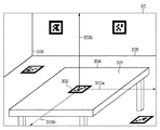
次に、図3を参照して、本実施形態における三次元位置姿勢情報の概念を説明する。図3は、第1の実施形態におけるHMDの撮像画像を用いた三次元位置姿勢情報を説明するための図である。 Next, the concept of the three-dimensional position / orientation information in the present embodiment will be described with reference to FIG. FIG. 3 is a diagram for describing three-dimensional position and orientation information using a captured image of the HMD in the first embodiment.
HMD10の撮像ユニット101によって取得した撮像画像30において、現実空間内に設置されたマーカ302には、予めMR空間内における絶対位置姿勢情報、又は任意の絶対位置姿勢に対する相対位置姿勢情報が与えられる。マーカ検出部102は、撮像画像データ中からマーカ302を検出する。位置姿勢情報生成部103は、検出されたマーカ302の大きさや形状、塗りつぶしのパターンなどの情報から、三次元位置姿勢情報を算出する。本実施形態において三次元位置姿勢情報は、マーカ302の持つ位置姿勢情報を基準としたHMD10本体の相対的位置関係、およびHMD装着者がマーカを観察している向きを示す情報である。
In the captured
図3では、一例として、マーカ302の中心部を原点とする三次元座標系(303a、303b、303c)をMR空間内における座標系として想定しているが、座標系の原点はマーカ302上に設定する必要はない。たとえば、座標系の原点とマーカ302との相対的位置関係を対応付けることにより、任意の位置に設定してもよい。また、本実施形態では、図3に示すように複数のマーカを同時に用いることが可能である。複数のマーカを用いることにより、位置姿勢情報を算出可能な領域を拡大できる。
In FIG. 3, as an example, a three-dimensional coordinate system (303a, 303b, 303c) having the origin at the center of the
また、複数のマーカを同時に用いる場合、マーカ同士の相対的な位置姿勢の関係を予め算出し、各マーカの位置姿勢情報を登録しておくことによって、より精度の高いHMD10の三次元位置姿勢情報の算出が可能となる。複数のマーカを同時に使用する場合でも、図3に示したような内部の塗りつぶしパターンによって方向まで識別が可能なマーカを使用しなくてもよい。例えば、特定色を用いたカラーマーカーや、LEDなどの発光素子のような方向性を持たないマーカを利用することもできる。また、事前に用意されたマーカではなく、テーブルの輪郭線304、壁や床の境界線305やコーナーの特徴点306のような、撮像画像中に含まれる自然特徴や、画像中の任意の色を抽出して指標として用いることもできる。
When a plurality of markers are used at the same time, the relationship between the relative positions and orientations of the markers is calculated in advance, and the position and orientation information of each marker is registered, so that the three-dimensional position and orientation information of the
上述してきたような、同一種類のマーカを複数用いたり、数種類のマーカを同時に用いたり、マーカ情報と画像中の自然特徴の情報を組み合わせて用いたりすることによって、より高い精度で三次元位置姿勢情報を生成することができる。また、複数のマーカや自然特徴は相対的な位置関係が算出され、システムに登録されるため、全てのマーカや特徴点が画像内に表示されていなくても、それぞれのマーカや自然特徴の位置姿勢を推定することが可能である。 By using multiple markers of the same type as described above, using several types of markers at the same time, or using a combination of marker information and natural feature information in the image, the 3D position and orientation can be improved with higher accuracy. Information can be generated. In addition, since the relative positional relationship between multiple markers and natural features is calculated and registered in the system, even if not all markers and feature points are displayed in the image, the position of each marker or natural feature It is possible to estimate the posture.
本実施形態のワイヤレスMRシステムの三次元位置姿勢情報の生成には、上述のHMD10に内蔵された主観カメラ(内部イメージセンサ)で撮像した画像情報を用いる方法の他に、各種センシングデバイスによるセンシング情報を用いる方法がある。センシングデバイスの例としては、磁気センサ、ジャイロセンサなどのように、HMD10に取り付けて使用するタイプのデバイスがある。また、客観カメラ(外部イメージセンサ)などのように、HMD10以外に取り付けて使用するタイプのデバイスもある。客観カメラを使用する場合は、HMD本体にもマーカを取り付けて検出対象とする。
In order to generate the three-dimensional position and orientation information of the wireless MR system of the present embodiment, in addition to the method using image information captured by the subjective camera (internal image sensor) built in the
これらのセンシングデバイスは一種類のみで使用することも、複数の種類のデバイスを組み合わせて使用することも可能である。また、HMD10に内蔵された主観カメラで撮像した画像情報と、センシングデバイスで取得したセンシング情報を組み合わせて三次元位置姿勢情報の生成を行うことによって、より精度の高い三次元位置姿勢情報を得ることができる。また、主観カメラでマーカが見えていないような状態でも三次元位置姿勢情報を取得することが可能となる。
These sensing devices can be used alone, or a plurality of types of devices can be used in combination. Further, by generating 3D position and orientation information by combining image information captured by a subjective camera built in the
次に図5a乃至図5eを参照して、本実施形態におけるワイヤレスMRシステムのエリア構成方法について説明する。図5aは、本発明の特徴を説明する第1の実施形態におけるワイヤレスMRシステムのエリア構成方法について説明する図である。 Next, an area configuration method of the wireless MR system in the present embodiment will be described with reference to FIGS. 5a to 5e. FIG. 5a is a diagram for explaining an area configuration method of the wireless MR system in the first embodiment for explaining the features of the present invention.
図5aのワイヤレスMRシステムは、HMD501、画像処理装置502a、b、c、d、e、ハブ503、システム管理サーバ504で構成される。また、空間内には、空間内における絶対位置姿勢情報を与えられた基準マーカ505と、位置姿勢情報算出のために用いるための位置情報マーカ(第1の指標)506a、b、c、d、eが配置されている。画像処理装置502には接続情報用マーカ(第2の指標)が添付され、該接続情報用マーカには、マーカIDと、MACアドレスや利用周波数チャネルといった無線接続に関する情報とが添付されている。よって、HMD501の撮像ユニット101により、マーカID、MACアドレス、利用周波数チャネルの情報を画像データより取得することができる。画像データに含まれるマーカID、MACアドレス、利用周波数チャネルは、文字認識によってもよいし、該情報が二次元バーコードにより表現されている場合には、該二次元バーコードから読み取ることができる。
The wireless MR system shown in FIG. 5A includes an
図5aでは、説明にあたり視覚的に理解しやすいように位置情報マーカ506および接続情報用マーカのパターンを、それぞれ数字、アルファベットの形状になるように設定している。マーカに関する情報は、図5bに示すマーカリスト115に格納される。マーカリスト115は、システム管理サーバ504で管理される。マーカリスト115は、ID511、種類512、位置姿勢情報513及び無線接続情報514が関連づけて登録されている。
In FIG. 5a, the patterns of the position information marker 506 and the connection information marker are set so as to have numbers and alphabets, respectively, so that the description can be easily understood visually. Information about the marker is stored in the
ID511は、登録されるマーカを一意に識別するための識別情報である。種類512は、マーカが、第1の指標としての位置情報マーカと第2の指標としての接続情報用マーカとのいずれであるか判別するための情報として、「接続情報」、「位置姿勢情報」のいずれかが登録される。位置姿勢情報513は、該マーカのMR空間における位置姿勢の情報である。第1の位置姿勢情報として、位置情報マーカの位置姿勢情報と、第2の位置姿勢情報として接続情報用マーカの位置姿勢情報とが登録される。無線接続情報514は、画像処理装置502のMACアドレスと利用周波数チャネルの情報が登録される。
ID511 is identification information for uniquely identifying a registered marker. The
本実施形態では、まず、マーカから取得したID511、種類512、無線接続情報514(接続情報用マーカのみ)がマーカリスト115に格納され、次いで、位置姿勢情報513に画像処理装置502により算出された値が登録される。
In this embodiment, first, the
エリア構成の際、まず、HMD501は、自身の周囲の画像処理装置502に接続要求をブロードキャストし、応答のあった画像処理装置502のうちの一つと無線通信を開始する。この時点では、HMD501は、画像処理装置502a、b、c、d、eの内、どの場所に設置された画像処理装置502と通信を行っているかは判断できていなくてもよい。
In the area configuration, first, the
続いて、HMD501といずれかの画像処理装置502が通信を行っている状態で、HMD501を用いて基準マーカ505を含む撮像画像を取得する。図中の囲い線507は、撮像画像に含まれるマーカを示している。撮像画像内に、システム管理サーバ504で管理しているマーカリスト115に位置姿勢情報が登録されていない未登録のマーカが含まれていた場合、基準マーカ505の位置姿勢情報から、未登録のマーカの位置姿勢情報を算出し、リストに登録する。
Subsequently, a captured image including the
ここでは、画像処理装置502aに添付された接続情報用マーカの位置姿勢情報を、基準マーカ505を用いて算出し、図5bのリストのID511の"A"に算出した位置姿勢情報を登録することとなる。このような処理の流れによって、画像処理装置502aに添付されたマーカについて、ID511、位置姿勢情報513及び無線接続情報514が対応付けられる。
Here, the position / orientation information of the connection information marker attached to the
次に、図5cで示すようにHMD501が移動することによって、未登録のマーカが撮像画像内に検出された場合を考える。この場合、マーカリスト115に位置姿勢情報513が登録されている既知のマーカの位置姿勢情報との相対的な関係から、未登録のマーカの位置姿勢情報を算出し、マーカリスト115に登録する。
Next, consider a case where an unregistered marker is detected in the captured image by moving the
図5cでは、画像処理装置502bに添付された接続情報用マーカと、位置情報マーカ506aが未登録のマーカに該当する。そこで、画像処理装置502aに添付された接続情報用マーカを基準として、各マーカの位置姿勢情報を算出する。その結果、図5dに示すように、マーカリスト115の位置姿勢情報513に算出された値が登録される。
In FIG. 5c, the connection information marker attached to the
以上の処理を繰り返し行い、すべてのマーカの位置姿勢情報513のリストへの登録が完了すると、図5eに示すようなマーカリスト115が完成する。マーカリスト115には、すべてのマーカIDが登録されているため、すべてのマーカの位置姿勢情報の登録が完了したかどうかを判断することが可能である。したがって、未登録のマーカがエリア内に存在する場合には、その内容をHMD501の表示ユニット109に表示してユーザーに通知することにより、マーカ登録の漏れをなくすことができる。
When the above process is repeated and registration of the position /
図5eのマーカリストをシステム内で管理することにより、画像処理装置502の接続情報と位置姿勢情報の対応関係が明らかとなる。そこで、図6に示すような画面を、HMD装着者に対して提供することができる。図6は、発明の第1の実施形態に対応する通信中の画像処理装置の表示機能について説明するための図である。 By managing the marker list in FIG. 5e in the system, the correspondence between the connection information and the position / orientation information of the image processing apparatus 502 becomes clear. Therefore, a screen as shown in FIG. 6 can be provided to the HMD wearer. FIG. 6 is a diagram for explaining a display function of the image processing apparatus in communication corresponding to the first embodiment of the invention.
図6において、HMD装着者601には、HMD201の表示ユニット109に画面602に示すような画面が表示されている。画面602に示すように、HMD装着者601が画像処理装置603に添付されたマーカ604を観察すると、マーカ検出部102によりマーカ604の情報が抽出され、マーカリスト115から対応する接続情報が抽出される。そして、画面602の領域605に示されるように、現在HMD201が接続している画像処理装置603を明示するとともに、画像処理装置603に関する情報をHMD装着者601に提示できる。
In FIG. 6, a screen as shown on a
同様に、登録済みのマーカをHMD201で観察した際に、識別子を付けて表示を行うこともできる。また、マーカリストに登録された位置姿勢情報は、システム動作中に適宜、更新することができる。
Similarly, when a registered marker is observed with the
例えば、画像処理装置502bの設置位置が、マーカリストに登録されている情報と異なることが検出された場合に、現在の位置姿勢情報を算出し、マーカリストを更新する。設置位置変化の検出は、周囲の複数マーカとの相対位置関係やセンサ情報を用いることで実現する。マーカリストの情報を更新可能にすることによって、一度エリアを構成した後に、HMDと画像処理装置との通信状態を確認しながら、画像処理装置の設置位置を調整することが可能となる。また、以上に説明してきたように、マーカリストはシステム管理サーバ504で一元管理を行っており、HMDは個々で取得したマーカの位置姿勢情報を送信しているだけであるため、複数のHMDを同時に用いてエリア構成を行うことが可能である。
For example, when it is detected that the installation position of the
次に、図7を参照して、本実施形態に対応する空間内に新規のマーカが追加された場合、或いは、マーカの設置位置が変更された場合の処理について説明する。図7は、発明の第1の実施形態に対応するマーカ情報登録時の処理の流れの一例を示すフローチャートである。図7に対応する処理は、各機能ブロックにおいて対応する処理プログラムを実行することにより実現される。 Next, a process when a new marker is added in the space corresponding to the present embodiment or when the marker installation position is changed will be described with reference to FIG. FIG. 7 is a flowchart showing an example of the flow of processing when registering marker information corresponding to the first embodiment of the invention. The processing corresponding to FIG. 7 is realized by executing a processing program corresponding to each functional block.
ステップS701では、HMD10は、周囲の画像処理装置11に対して接続要求を無線I/F105でブロードキャストし、無線接続を試みる。周囲の画像処理装置11のいずれかと接続が成功した場合は(ステップS702において「YES」)、ステップS703の処理へ移行する。一方、接続に失敗した場合は(ステップS702において「NO」)、ステップ701に戻り、接続が成功するまでブロードキャストを繰り返す。
In step S <b> 701, the
ステップS703の処理では、HMD10の撮像ユニット101によって撮像を行い、撮像画像を取得する。続いてマーカ検出部102が撮像画像内からマーカを検出を行い、マーカを検出できた場合は(ステップS704において「YES」)、ステップS705へ移行する。一方、マーカを検出できなかった場合は(ステップS704において「NO」)、ステップS703に戻り、撮像画像内からマーカを検出できるまで撮像を繰り返す。
In the process of step S703, imaging is performed by the
ステップS704でマーカを検出した場合、ステップS705では、位置姿勢情報生成部103が検出したマーカの画像からIDを判定する。また、ステップS706では、位置姿勢情報生成部103がマーカリスト115をシステム管理サーバ12から取得し、マーカリスト115内に既に位置姿勢情報が登録されている撮像画像内のマーカ情報を取得する。続くステップS707では、位置姿勢情報生成部103が、取得したマーカ情報やセンサで取得したセンシング情報を用いて、ステップS704で検出したマーカの位置姿勢情報を算出する。
When a marker is detected in step S704, in step S705, an ID is determined from the marker image detected by the position and orientation
撮像画像内のマーカの位置姿勢情報の算出に成功した場合は(ステップS708において「YES」)、ステップS709に移行する。一方、算出できなかった場合は(ステップS708において「NO」)、ステップS703に戻り、再び撮像画像の取得を行う。ステップS709では、位置姿勢情報生成部103が算出したマーカの位置姿勢情報が、すでにマーカリスト115に登録されているか否かを判定する。算出したマーカの位置姿勢情報がマーカリストに登録されていない場合は(ステップS709において「NO」)、ステップS710において、リスト管理部114がマーカリスト115に位置姿勢情報を登録し、本処理を終了する。
If the position / orientation information of the marker in the captured image has been successfully calculated (“YES” in step S708), the process proceeds to step S709. On the other hand, if it cannot be calculated (“NO” in step S708), the process returns to step S703, and the captured image is acquired again. In step S <b> 709, it is determined whether the marker position / orientation information calculated by the position / orientation
算出したマーカの位置姿勢情報が既にマーカリストに登録されていた場合は(ステップS709において「YES」)、ステップS711に移行する。ステップS711では、位置姿勢情報生成部103がマーカリスト115に登録されている位置姿勢情報と比較して変化があるか否かを判定する。もし、登録済みの位置姿勢情報から変化していると判定された場合は(ステップS711において「YES」)、ステップS710に移行して最新の位置姿勢情報を登録する。一方、登録済みの位置姿勢情報と変化していないと判定された場合は(ステップS711において「NO」)、ステップS703に戻り、再び撮像画像の取得を行う。
If the calculated marker position / orientation information has already been registered in the marker list (“YES” in step S709), the process proceeds to step S711. In step S <b> 711, the position / orientation
以上のようにして、位置姿勢情報が登録されていないマーカや、位置姿勢情報に変化のあったマーカについては、マーカリスト115の位置姿勢情報513の登録内容を更新することができる。
As described above, the registration contents of the position /
次に、図4を参照して本実施形態に対応するワイヤレスMRシステムにおけるエリア構成と通信切替処理について説明する。図4は、発明の第1の実施形態におけるワイヤレスMRシステムのエリア構成と通信切替処理を説明するための図である。 Next, an area configuration and communication switching processing in the wireless MR system corresponding to the present embodiment will be described with reference to FIG. FIG. 4 is a diagram for explaining the area configuration and the communication switching process of the wireless MR system in the first embodiment of the invention.
本実施形態におけるワイヤレスMRシステムは、HMD401が画像処理装置402a、b、c、d、eのいずれかと一対一で無線通信を行っている。また、画像処理装置402で生成されたCG画像とHMDで撮影された撮像画像とが合成されたMR画像を表示することにより、HMD装着者がMR空間を体験することができる。
In the wireless MR system in this embodiment, the
ここでは、画像処理装置402a、b、c、d、eはそれぞれ、405a、b、c、d、eで示した周波数チャネルを用いて通信を行うものとする。
Here, the
画像処理装置402a、b、c、d、eは、ハブ403を介してシステム管理サーバ404と有線接続されている。システム管理サーバ404は、三次元位置姿勢情報や接続情報の管理、通信切り替えの制御機能を有する。本実施形態では、システム管理サーバ404を別ハードウェアとしているが、システム管理サーバ404の機能を画像処理装置402に実装することも可能である。システム管理サーバ404の機能を画像処理装置402に実装することで、ハードウェアを一台削減することができ、システム全体のコストの低減が見込まれる。
The
HMD401が図中の位置に存在するとき、最も距離の近い画像処理装置402dと無線通信を行っている。このときHMDは、画像処理装置402dに設定されたCh5の周波数チャネルを利用して画像処理装置402dと通信を行っている。HMD装着者が移動し、図中のHMD401'の位置に移動すると、画像処理装置402dとの距離が遠くなり、電波強度が悪化するため、安定した通信状態を維持することが困難になる。
When the
このような場合、HMD401'は現在位置から最も距離の近い画像処理装置402aに設定されたCh1の周波数チャネルを利用して画像処理装置402aと接続するように切替制御を行う。この切替制御のために、まず、その時点で撮像ユニット101で撮像された画像データに含まれるマーカの位置姿勢情報と、マーカリスト115に含まれる位置姿勢情報のうち種類512が「接続情報」である位置姿勢情報とを比較する。比較の結果、距離が最も近い「接続情報」のマーカを選択する。図4の例では、当該マーカはHMD401'と最も距離の近い画像処理装置402aのマーカに該当することとなる。
In such a case, the
以上の切り替え制御を行うことで、一つの画像処理装置で通信できるエリアでは補えないような、広い領域でMR空間を体験することが可能となる。このような切り替え処理を実現するために、画像処理装置402に設定された周波数チャネル情報と設置位置情報、およびHMD401の位置情報をシステム管理サーバ404で管理することが必要となる。
By performing the above switching control, it is possible to experience the MR space in a wide area that cannot be compensated for in an area where communication can be performed with one image processing apparatus. In order to realize such switching processing, it is necessary to manage the frequency channel information and installation position information set in the image processing apparatus 402 and the position information of the
以上説明してきたように、記載のシステム構成を用いることにより、ユーザーは、HMDを装着して、マーカや画像処理装置の配置された空間内を歩き回るだけで、ワイヤレスMRシステムのエリア構成を行うことができる。よって、マーカの位置姿勢情報や画像処理装置の接続情報等の登録にかかるユーザー負荷を大幅に軽減することが可能となる。また、マーカや画像処理装置の設置位置姿勢の変化を検出し、マーカリストを更新できるため、通信状況を確認しながら、画像処理装置の配置を変えても、位置姿勢情報の変更が速やかに行うことが可能である。さらに、画像処理装置の位置姿勢情報、および接続情報をシステム管理サーバで同時に管理しているため、HMDの位置に応じて、接続する画像処理装置を切り換える制御を行うことができる。 As described above, by using the described system configuration, the user can perform the area configuration of the wireless MR system simply by wearing the HMD and walking around the space where the marker and the image processing apparatus are arranged. Can do. Therefore, it is possible to greatly reduce the user load related to registration of marker position and orientation information, connection information of the image processing apparatus, and the like. In addition, since the change of the installation position and orientation of the marker and the image processing apparatus can be detected and the marker list can be updated, even if the arrangement of the image processing apparatus is changed while checking the communication status, the position and orientation information is quickly changed. It is possible. Furthermore, since the position and orientation information of the image processing apparatus and the connection information are simultaneously managed by the system management server, it is possible to perform control for switching the image processing apparatus to be connected according to the position of the HMD.
(第2の実施形態)
次に、発明の第2の実施形態を図に従って説明する。上述の第1の実施形態では、システム管理サーバおよび画像処理装置側でマーカリストの管理、切り替え制御を行った。これに対し、本実施形態では、HMD側でマーカリストの管理、切り替え制御を行うことを特徴とする。この点を中心に内容を説明する。
(Second Embodiment)
Next, a second embodiment of the invention will be described with reference to the drawings. In the first embodiment described above, marker list management and switching control are performed on the system management server and the image processing apparatus side. In contrast, the present embodiment is characterized in that marker list management and switching control are performed on the HMD side. The contents will be described focusing on this point.
図8は、発明の第2の実施形態に対応するワイヤレスMRシステム全体の機能ブロックの一例を示す図である。本実施形態においても、第1の実施形態と同様に、まずは、エリア構成時の動作から説明する。 FIG. 8 is a diagram showing an example of functional blocks of the entire wireless MR system corresponding to the second embodiment of the invention. Also in the present embodiment, as in the first embodiment, first, the operation during area configuration will be described.
HMD10は、撮像ユニット101で現実空間画像の取得を行い、マーカ検出部102で撮像画像からマーカを検出し、ID情報を抽出する。位置姿勢情報生成部103では、リスト管理部801を介してマーカリスト802を参照する。リスト管理部801で、マーカ検出部102で撮像画像から検出されたマーカの中に、位置姿勢情報がマーカリスト802に登録されていないマーカが存在すると判定された場合、位置姿勢情報生成部103で位置姿勢情報を算出する。位置姿勢情報生成部103は、撮像画像内に検出された既に位置姿勢情報が登録されている既知のマーカ、および三次元位置姿勢センサ104で取得したセンシング情報を利用して、位置姿勢情報の生成を行う。また、生成された位置姿勢情報は、リスト管理部801により、マーカリスト802に登録される。
The
以上が本実施形態における、マーカ情報登録時のワイヤレスMRシステムの動作である。エリア構成を行う際の処理内容において、第1の実施形態と大きく異なるのは、マーカリスト802を参照するために画像処理装置と無線通信を行うか否かの点にある。
The above is the operation of the wireless MR system when registering marker information in the present embodiment. The processing contents when performing the area configuration differ greatly from the first embodiment in whether or not wireless communication is performed with the image processing apparatus in order to refer to the
本実施形態では、マーカリスト802をHMD10内で管理しているため、エリア構成時に無線通信を行う必要がなく、HMD10の省電力化が実現できる。ただし、複数のHMD10を利用してエリア構成を行う際には、それぞれのHMD10で取得した情報をやりとりするために無線通信を行う必要があるので、HMD10の処理負荷が増大した分、MR体験可能時間は短くなる。
In this embodiment, since the
続いて、本実施形態におけるユーザのMR体験時の動作について説明するが、MR画像を表示する処理の流れは第1の実施形態と同様である。MR体験時の処理内容において、第1の実施形態と大きく異なるのは、切り替え制御の主体がHMD10側にあるという点である。
Next, the operation of the user during the MR experience in this embodiment will be described. The flow of processing for displaying the MR image is the same as that in the first embodiment. The content of processing at the time of MR experience is greatly different from that of the first embodiment in that the main body of switching control is on the
本実施形態では、HMD10内の位置姿勢情報生成部103で生成される位置姿勢情報によって、HMD10の移動を検出してから、すぐにマーカリスト802内のマーカ情報を参照し、切り替え制御部803で切り替え制御を開始することができる。従って、第1の実施形態の切替制御時に発生していた画像処理装置11を介してシステム管理サーバ12にアクセスし、システム管理サーバ12からの切替指示を受信するまでの待機時間を省略することができる。
In the present embodiment, after detecting the movement of the
本実施形態では、切り替えのための待機時間が短縮されることで、切替時の伝送エラーやフレーム落ちの頻度を減少させることができる。 In this embodiment, the waiting time for switching is shortened, so that the frequency of transmission errors and frame dropping at the time of switching can be reduced.
以上説明してきたように、HMD10側でマーカリスト802を管理し、切替制御を行う本実施形態のシステム構成を用いることで、全体のシステム構成からシステム管理サーバを除くことができ、システム構成の簡略化を実現できる。但し、HMDの機能の複雑化に伴いサイズが増大し、HMD自身の処理負荷は増大するが、エリア構成時に、電力消費の大半を占める無線通信を行わなくて済むため、結果としてMR体験可能時間の長時間化が期待できる。
As described above, by using the system configuration of this embodiment that manages the
さらには、切替制御時のシステム管理サーバとの通信時間を省くことができるため、切り替えにかかる処理時間を短縮することができ、エラーやフレーム落ちの頻度を減少させることが可能となる。ただし、上述したように、機能の複雑化によりHMDにおける処理負荷が増大するため、システム実現のためには、HMDの処理能力が、第1の実施形態のシステム構成を実現するために必要なHMDの処理能力よりも、高性能であることが要求される。 Furthermore, since the communication time with the system management server at the time of switching control can be saved, the processing time required for switching can be shortened, and the frequency of errors and frame dropping can be reduced. However, as described above, the processing load in the HMD increases due to the complexity of the functions. Therefore, in order to realize the system, the processing capability of the HMD is required to realize the system configuration of the first embodiment. It is required to have a higher performance than the processing capability.
[その他の実施形態]
なお、本発明は、複数の機器(例えばホストコンピュータ、インタフェイス機器、リーダ、プリンタなど)から構成されるシステムに適用しても、一つの機器からなる装置(例えば、複写機、ファクシミリ装置など)に適用してもよい。
[Other Embodiments]
Note that the present invention can be applied to a system including a plurality of devices (for example, a host computer, an interface device, a reader, and a printer), and a device (for example, a copying machine and a facsimile device) including a single device. You may apply to.
また、本発明の目的は、前述した機能を実現するコンピュータプログラムのコードを記録した記憶媒体を、システムに供給し、そのシステムがコンピュータプログラムのコードを読み出し実行することによっても達成される。この場合、記憶媒体から読み出されたコンピュータプログラムのコード自体が前述した実施形態の機能を実現し、そのコンピュータプログラムのコードを記憶した記憶媒体は本発明を構成する。また、そのプログラムのコードの指示に基づき、コンピュータ上で稼働しているオペレーティングシステム(OS)などが実際の処理の一部または全部を行い、その処理によって前述した機能が実現される場合も含まれる。 The object of the present invention can also be achieved by supplying, to a system, a storage medium that records the code of a computer program that realizes the functions described above, and the system reads and executes the code of the computer program. In this case, the computer program code itself read from the storage medium realizes the functions of the above-described embodiments, and the storage medium storing the computer program code constitutes the present invention. In addition, the operating system (OS) running on the computer performs part or all of the actual processing based on the code instruction of the program, and the above-described functions are realized by the processing. .
さらに、以下の形態で実現しても構わない。すなわち、記憶媒体から読み出されたコンピュータプログラムコードを、コンピュータに挿入された機能拡張カードやコンピュータに接続された機能拡張ユニットに備わるメモリに書込む。そして、そのコンピュータプログラムのコードの指示に基づき、その機能拡張カードや機能拡張ユニットに備わるCPUなどが実際の処理の一部または全部を行って、前述した機能が実現される場合も含まれる。 Furthermore, you may implement | achieve with the following forms. That is, the computer program code read from the storage medium is written into a memory provided in a function expansion card inserted into the computer or a function expansion unit connected to the computer. Then, based on the instruction of the code of the computer program, the above-described functions are realized by the CPU or the like provided in the function expansion card or function expansion unit performing part or all of the actual processing.
本発明を上記記憶媒体に適用する場合、その記憶媒体には、先に説明したフローチャートに対応するコンピュータプログラムのコードが格納されることになる。 When the present invention is applied to the above storage medium, the computer program code corresponding to the flowchart described above is stored in the storage medium.
10・・・ HMD
11・・・ 画像処理装置
12・・・ システム管理サーバ
101・・・ 撮像ユニット
102・・・ マーカ検出部
103・・・ 位置姿勢情報生成部
104・・・ 三次元位置姿勢センサ
105・・・ 無線I/F(HMD)
106・・・ 無線I/F(画像処理装置)
107・・・ CG画像描画部
108・・・ 画像合成部
109・・・ 表示ユニット
110・・・ 接続管理部(画像処理装置)
111・・・ 有線I/F(画像処理装置)
112・・・ ハブ
113・・・ 有線I/F(システム管理サーバ)
114・・・ リスト管理部
115・・・ マーカリスト
116・・・ 切り替え制御部
117・・・ 接続管理部(HMD)
10 ... HMD
DESCRIPTION OF
106: Wireless I / F (image processing apparatus)
107 CG
111... Wired I / F (image processing device)
112 ...
114 ...
Claims (7)
前記現実空間に配置された第1の指標につき、該第1の指標の第1の位置姿勢情報を登録し、前記画像処理装置に添付された第2の指標につき、該第2の指標の第2の位置姿勢情報と前記表示装置が前記画像処理装置と無線通信するための接続情報とを関連づけて登録するリストを登録する登録手段と、
前記表示装置と通信する前記複数の画像処理装置のいずれかとの通信状況が悪化した場合に、前記撮像手段により生成された撮像画像データに含まれる前記第1の指標について前記リストに登録されている第1の位置姿勢情報と、前記リストに登録されている前記第2の位置姿勢情報とに基づいて、前記表示装置と最も距離の近い画像処理装置を選択する選択手段と
を備え、
前記表示装置は、通信する画像処理装置を、前記選択手段により選択された前記最も距離の近い画像処理装置に切り替えることを特徴とする画像処理システム。 An imaging unit that captures a real space and generates captured image data, a display device that synthesizes the captured image data with a CG image and displays it on the display unit, and generates the CG image and wirelessly communicates with the display device An image processing system comprising a plurality of image processing devices provided by
The first position and orientation information of the first index is registered for the first index arranged in the real space, and the second index of the second index is attached to the second index attached to the image processing apparatus. Registration means for registering a list for registering the position and orientation information of 2 and the connection information for the display device to wirelessly communicate with the image processing device;
When the communication status with any of the plurality of image processing devices communicating with the display device deteriorates, the first index included in the captured image data generated by the imaging unit is registered in the list. Selection means for selecting an image processing apparatus closest to the display device based on first position and orientation information and the second position and orientation information registered in the list;
The display apparatus switches an image processing apparatus to be communicated to the image processing apparatus having the shortest distance selected by the selection unit.
前記表示装置は、
前記撮像画像データから、前記第1の指標又は第2の指標を検出する指標検出手段と、
前記指標検出手段により検出された指標の位置姿勢情報を、前記リストに登録された他の指標の位置姿勢情報を利用して生成する位置姿勢情報生成手段と、
前記検出された指標が前記リストに登録されているか否かを判定する判定手段と
を備え、
前記検出された指標が前記リストに登録されていないと判定され、かつ、該検出された指標が前記第2の指標の場合に、前記リストには該検出された第2の指標について、該第2の指標について生成された前記第2の位置姿勢情報と、前記第2の指標から抽出された前記接続情報とが追加されることを特徴とする請求項1に記載の画像処理システム。 The connection information is given to the second indicator,
The display device
Index detecting means for detecting the first index or the second index from the captured image data;
Position and orientation information generating means for generating the position and orientation information of the index detected by the index detection means by using the position and orientation information of other indices registered in the list;
Determination means for determining whether or not the detected index is registered in the list,
When it is determined that the detected index is not registered in the list, and the detected index is the second index, the list includes the second index for the detected second index. The image processing system according to claim 1, wherein the second position and orientation information generated for the second index and the connection information extracted from the second index are added.
前記判定手段により一致しないと判定された場合に、該登録されている指標の前記位置姿勢情報が、前記位置姿勢情報生成手段で生成された位置姿勢情報により更新されることを特徴とする請求項2または3に記載の画像処理システム。 When the detected index is already registered in the list, the determining unit matches the position and orientation information of the registered index with the position and orientation information generated by the position and orientation information generating unit. Determine whether or not to
The position / orientation information of the registered index is updated with the position / orientation information generated by the position / orientation information generation unit when the determination unit determines that they do not match. The image processing system according to 2 or 3.
前記システム管理サーバは、前記登録手段と、前記選択手段とを備え、前記最も距離の近い画像処理装置への切替指示を、前記画像処理装置を介して前記表示装置へ通知することを特徴とする請求項1乃至4のいずれか1項に記載の画像処理システム。 The image processing system further includes a system management server that communicates with the image processing apparatus,
The system management server includes the registration unit and the selection unit, and notifies the display device of an instruction to switch to the closest image processing device via the image processing device. The image processing system according to claim 1.
前記表示装置の登録手段が、前記現実空間に配置された第1の指標につき、該第1の指標の第1の位置姿勢情報を登録し、前記画像処理装置に添付された第2の指標につき、該第2の指標の第2の位置姿勢情報と前記表示装置が前記画像処理装置と無線通信するための接続情報とを関連づけて登録するリストを登録する登録工程と、
前記表示装置の選択手段が、前記表示装置と通信する前記複数の画像処理装置のいずれかとの通信状況が悪化した場合に、前記撮像手段により生成された撮像画像データに含まれる前記第1の指標について前記リストに登録されている第1の位置姿勢情報と、前記リストに登録されている前記第2の位置姿勢情報とに基づいて、前記表示装置と最も距離の近い画像処理装置を選択する選択工程と、
を備え、
前記表示装置は、通信する画像処理装置を、前記選択工程において選択された前記最も距離の近い画像処理装置に切り替えることを特徴とする画像処理システムの制御方法。 An imaging unit that captures a real space and generates captured image data, a display device that synthesizes the captured image data with a CG image and displays it on the display unit, and generates the CG image and wirelessly communicates with the display device A method for controlling an image processing system comprising a plurality of image processing devices provided by
The registration means of the display device registers the first position / orientation information of the first index for the first index arranged in the real space, and for the second index attached to the image processing apparatus. A registration step of registering a list for associating and registering the second position and orientation information of the second index and connection information for the display device to wirelessly communicate with the image processing device;
The first indicator included in the captured image data generated by the imaging unit when the selection unit of the display device deteriorates the communication status with any of the plurality of image processing devices communicating with the display device Selection for selecting an image processing device closest to the display device based on the first position and orientation information registered in the list and the second position and orientation information registered in the list Process,
With
The display apparatus switches an image processing apparatus to be communicated to the image processing apparatus with the shortest distance selected in the selection step.
Priority Applications (1)
| Application Number | Priority Date | Filing Date | Title |
|---|---|---|---|
| JP2007333190A JP4991515B2 (en) | 2007-12-25 | 2007-12-25 | Image processing system, image processing system control method, and computer program |
Applications Claiming Priority (1)
| Application Number | Priority Date | Filing Date | Title |
|---|---|---|---|
| JP2007333190A JP4991515B2 (en) | 2007-12-25 | 2007-12-25 | Image processing system, image processing system control method, and computer program |
Publications (3)
| Publication Number | Publication Date |
|---|---|
| JP2009157526A JP2009157526A (en) | 2009-07-16 |
| JP2009157526A5 JP2009157526A5 (en) | 2011-02-17 |
| JP4991515B2 true JP4991515B2 (en) | 2012-08-01 |
Family
ID=40961509
Family Applications (1)
| Application Number | Title | Priority Date | Filing Date |
|---|---|---|---|
| JP2007333190A Expired - Fee Related JP4991515B2 (en) | 2007-12-25 | 2007-12-25 | Image processing system, image processing system control method, and computer program |
Country Status (1)
| Country | Link |
|---|---|
| JP (1) | JP4991515B2 (en) |
Families Citing this family (8)
| Publication number | Priority date | Publication date | Assignee | Title |
|---|---|---|---|---|
| US8878912B2 (en) | 2009-08-06 | 2014-11-04 | Qualcomm Incorporated | Encapsulating three-dimensional video data in accordance with transport protocols |
| JP5812628B2 (en) * | 2011-02-25 | 2015-11-17 | 任天堂株式会社 | Information processing program, information processing method, information processing apparatus, and information processing system |
| JP5697487B2 (en) | 2011-02-25 | 2015-04-08 | 任天堂株式会社 | Image processing system, image processing method, image processing apparatus, and image processing program |
| JP5729761B2 (en) * | 2011-04-04 | 2015-06-03 | Necカシオモバイルコミュニケーションズ株式会社 | Display system and load balancing method |
| JP5844880B2 (en) * | 2012-03-01 | 2016-01-20 | パイオニア株式会社 | Head mounted display, calibration method and calibration program, and recording medium |
| US10775878B2 (en) * | 2015-04-10 | 2020-09-15 | Sony Interactive Entertainment Inc. | Control of personal space content presented via head mounted display |
| WO2020013313A1 (en) * | 2018-07-12 | 2020-01-16 | 株式会社東芝 | Omnidirectional photographing system and omnidirectional photographing method |
| CN113274043A (en) * | 2020-01-31 | 2021-08-20 | 佳能医疗系统株式会社 | Radiation diagnosis apparatus and radiation diagnosis method |
Family Cites Families (4)
| Publication number | Priority date | Publication date | Assignee | Title |
|---|---|---|---|---|
| JP2005142807A (en) * | 2003-11-06 | 2005-06-02 | Hitachi Maxell Ltd | Wireless communication terminal, wireless communication system, and wireless communication connection method |
| JP4367926B2 (en) * | 2004-05-17 | 2009-11-18 | キヤノン株式会社 | Image composition system, image composition method, and image composition apparatus |
| JP2007067723A (en) * | 2005-08-30 | 2007-03-15 | Matsushita Electric Ind Co Ltd | Mobile terminal apparatus and peripheral device selecting method |
| JP4527155B2 (en) * | 2005-12-28 | 2010-08-18 | 富士通株式会社 | Navigation information display system, navigation information display method, and program therefor |
-
2007
- 2007-12-25 JP JP2007333190A patent/JP4991515B2/en not_active Expired - Fee Related
Also Published As
| Publication number | Publication date |
|---|---|
| JP2009157526A (en) | 2009-07-16 |
Similar Documents
| Publication | Publication Date | Title |
|---|---|---|
| JP4991515B2 (en) | Image processing system, image processing system control method, and computer program | |
| JP5067850B2 (en) | System, head-mounted display device, and control method thereof | |
| US20210112427A1 (en) | Cross reality system with wireless fingerprints | |
| JP4679661B1 (en) | Information presenting apparatus, information presenting method, and program | |
| JP4642538B2 (en) | Image processing method and image processing apparatus | |
| JP6348741B2 (en) | Information processing system, information processing apparatus, information processing program, and information processing method | |
| US20140368426A1 (en) | Image processing system, image processing apparatus, storage medium having stored therein image processing program, and image processing method | |
| US20210279953A1 (en) | Cross reality system with wifi/gps based map merge | |
| US20080024523A1 (en) | Generating images combining real and virtual images | |
| US20120092371A1 (en) | Information processing apparatus, information processing method, program, and information processing system | |
| US10386633B2 (en) | Virtual object display system, and display control method and display control program for the same | |
| EP3128413A1 (en) | Sharing mediated reality content | |
| JP6615732B2 (en) | Information processing apparatus and image generation method | |
| WO2022052620A1 (en) | Image generation method and electronic device | |
| JP2016122392A (en) | Information processing apparatus, information processing system, control method and program of the same | |
| JP6730577B2 (en) | Information processing apparatus, information processing system, control method thereof, and program | |
| WO2021093703A1 (en) | Interaction method and system based on optical communication apparatus | |
| CN108803861B (en) | Interaction method, equipment and system | |
| US11238658B2 (en) | AR space image projecting system, AR space image projecting method, and user terminal | |
| JP2016129316A (en) | Communication apparatus, control method of the same, program, and communication system | |
| JP6941715B2 (en) | Display device, display program, display method and display system | |
| KR101729923B1 (en) | Method for implementing 3d image using screen image and augmented reality image and server and system implementing the same | |
| JP4125085B2 (en) | Image processing apparatus and image processing method | |
| CN111344776A (en) | Information processing apparatus, information processing method, and program | |
| WO2022172335A1 (en) | Virtual guide display device, virtual guide display system, and virtual guide display method |
Legal Events
| Date | Code | Title | Description |
|---|---|---|---|
| A521 | Request for written amendment filed |
Free format text: JAPANESE INTERMEDIATE CODE: A523 Effective date: 20101224 |
|
| A621 | Written request for application examination |
Free format text: JAPANESE INTERMEDIATE CODE: A621 Effective date: 20101224 |
|
| A977 | Report on retrieval |
Free format text: JAPANESE INTERMEDIATE CODE: A971007 Effective date: 20120314 |
|
| TRDD | Decision of grant or rejection written | ||
| A01 | Written decision to grant a patent or to grant a registration (utility model) |
Free format text: JAPANESE INTERMEDIATE CODE: A01 Effective date: 20120406 |
|
| A01 | Written decision to grant a patent or to grant a registration (utility model) |
Free format text: JAPANESE INTERMEDIATE CODE: A01 |
|
| A61 | First payment of annual fees (during grant procedure) |
Free format text: JAPANESE INTERMEDIATE CODE: A61 Effective date: 20120507 |
|
| R151 | Written notification of patent or utility model registration |
Ref document number: 4991515 Country of ref document: JP Free format text: JAPANESE INTERMEDIATE CODE: R151 |
|
| FPAY | Renewal fee payment (event date is renewal date of database) |
Free format text: PAYMENT UNTIL: 20150511 Year of fee payment: 3 |
|
| LAPS | Cancellation because of no payment of annual fees |