JP4125085B2 - Image processing apparatus and image processing method - Google Patents
Image processing apparatus and image processing method Download PDFInfo
- Publication number
- JP4125085B2 JP4125085B2 JP2002301651A JP2002301651A JP4125085B2 JP 4125085 B2 JP4125085 B2 JP 4125085B2 JP 2002301651 A JP2002301651 A JP 2002301651A JP 2002301651 A JP2002301651 A JP 2002301651A JP 4125085 B2 JP4125085 B2 JP 4125085B2
- Authority
- JP
- Japan
- Prior art keywords
- image
- mixed reality
- reality space
- viewpoint
- image processing
- Prior art date
- Legal status (The legal status is an assumption and is not a legal conclusion. Google has not performed a legal analysis and makes no representation as to the accuracy of the status listed.)
- Expired - Fee Related
Links
Images


Landscapes
- Processing Or Creating Images (AREA)
Description
【0001】
【発明の属する技術分野】
本発明は、現実空間の画像と仮想空間の画像とを重畳した複合現実空間画像を生成する画像処理装置、画像処理方法に関するものである。
【0002】
【従来の技術】
静止画や動画が撮像可能なカメラなどの撮像装置を用いて撮像した現実空間の画像に、コンピュータ内で生成された仮想物体の画像を重畳することで、複合現実空間の画像を生成することができる。そしてこの画像を表示装置の表示画面上に表示させることで、ユーザに提示することができる。
【0003】
また、ユーザが上記複合現実空間の画像を何らかの形で取得したい場合、従来では上記表示画面を更にカメラなどの撮像装置を用いて撮影し、電子データやフィルムに焼き付けることで、この画面に表示されている画像を取得してていた。
【0004】
【発明が解決しようとする課題】
しかし、上記方法では、表示装置に表示されている画像を撮影するために、得られる画像の画質が悪い上に、画像内に表示装置自体が含まれてしまうこともあった。
【0005】
さらには撮影者の望む視点位置、視線方向の複合現実空間の画像を撮影することはほとんど出来ないばかりでなく、観察者と仮想物体とが相互交流している様子を理解可能な興味深い画像を得ることは至難であった。
【0006】
本発明は以上の問題に鑑みてなされたものであり、複合現実空間画像を取得可能な画像処理装置、画像処理方法を提供することを目的とする。
【0007】
【課題を解決するための手段】
本発明の目的を達成するために、例えば本発明の画像処理装置は以下の構成を備える。
【0008】
すなわち、現実空間の画像を撮像する撮像装置を仮想空間における視点とし、前記現実空間と前記仮想空間とで共有される座標系における前記視点の位置姿勢に応じた仮想空間の画像を生成する生成部と、前記現実空間の画像と前記仮想空間の画像とを合成して複合現実空間画像を生成する合成部と、を有する複数の外部装置とのデータ通信が可能であると共に、プリント手段に接続されている画像処理装置であって、
前記複数の外部装置から2以上を選択する選択手段と、
前記選択手段が選択したそれぞれの外部装置の合成部が生成した複合現実空間画像を取得する取得手段と、
前記取得手段が取得したそれぞれの複合現実空間画像を縮小して並べることで、当該それぞれの複合現実空間画像を含む1枚の画像を生成する生成手段と、
前記生成手段が生成した1枚の画像を表示する表示手段と、
プリント指示を受け付ける手段と、
前記プリント指示が入力された場合には、前記選択手段が選択したそれぞれの外部装置に対して複合現実空間画像を要求し、当該要求に応じて前記選択手段が選択したそれぞれの外部装置から送信された複合現実空間画像を取得し、取得したそれぞれの複合現実空間画像を縮小して並べることで、当該それぞれの複合現実空間画像を含む1枚の画像を生成し、生成した1枚の画像を前記プリント手段に出力する出力手段と
を備えることを特徴とする。
【0011】
本発明の目的を達成するために、例えば本発明の画像処理方法は以下の構成を備える。
【0012】
すなわち、現実空間の画像を撮像する撮像装置を仮想空間における視点とし、前記現実空間と前記仮想空間とで共有される座標系における前記視点の位置姿勢に応じた仮想空間の画像を生成する生成部と、前記現実空間の画像と前記仮想空間の画像とを合成して複合現実空間画像を生成する合成部と、を有する複数の外部装置とのデータ通信が可能であると共に、プリント手段に接続されている画像処理装置が行う画像処理方法であって、
前記複数の外部装置から2以上を選択する選択工程と、
前記選択工程で選択したそれぞれの外部装置の合成部が生成した複合現実空間画像を取得する取得工程と、
前記取得工程で取得したそれぞれの複合現実空間画像を縮小して並べることで、当該それぞれの複合現実空間画像を含む1枚の画像を生成する生成工程と、
前記生成工程で生成した1枚の画像を表示する表示工程と、
プリント指示を受け付ける工程と、
前記プリント指示が入力された場合には、前記選択工程で選択したそれぞれの外部装置に対して複合現実空間画像を要求し、当該要求に応じて前記選択工程で選択したそれぞれの外部装置から送信された複合現実空間画像を取得し、取得したそれぞれの複合現実空間画像を縮小して並べることで、当該それぞれの複合現実空間画像を含む1枚の画像を生成し、生成した1枚の画像を前記プリント手段に出力する出力工程と
を備えることを特徴とする。
【0015】
【発明の実施の形態】
以下添付図面を参照して、本発明を好適な実施形態に従って詳細に説明する。
【0016】
[第1の実施形態]
図1は観察者と、この観察者に対して複合現実空間の画像を取得可能にする本実施形態に係るシステムの構成を示す図である。100は複合現実空間画像を観察する観察者である。110は観察者一人分の複合現実空間画像を生成する画像処理装置110で、パーソナルコンピュータ(PC)120、現実空間の動画像を撮像するビデオカメラ140、モニタ150で構成される処理装置である。PC120では仮想空間管理プログラムと複合現実空間画像生成プログラムが動作している。
【0017】
仮想空間管理プログラムはPC120により実行されることで仮想空間の状態を更新し、更新結果を複合現実空間画像生成プログラムに通知する機能を有する。複合現実空間画像生成プログラムはPC120により実行されることで、仮想空間管理プログラムから通知された仮想空間の状態に基づいて仮想空間画像をメモリ上に描画すると共に、ビデオカメラ140から取得した現実空間画像をメモリ上に描画された仮想空間画像に合成する。即ちメモリ上には複合現実空間画像が描画される。そしてメモリ上に描画された複合現実空間画像はモニタ150に表示される。
【0018】
観察者100はモニタ150に表示された複合現実空間画像を見ることで、複合現実空間画像を観察することができる。なお、モニタ150は複合現実空間画像だけでなく、PC120を操作する際に必要な情報(システムメッセージやシステムの設定画面など)を表示することもある。
【0019】
観察者100が手にしているのはシャッター160である。シャッター160はプッシュボタンスイッチで構成されており、スイッチが観察者100により押下されると、シャッター160からは押下されたことを示す信号がPC120に出力される。PC120がこの信号を検知すると、検知した時点でPC120のメモリに記憶されている複合現実空間画像をプリンタ170に出力する。
【0020】
プリンタ170は、その記録方式は特に限定するものではなく、PC120から送られた複合現実空間画像を紙やOHP等の記録媒体上に画像として記録することができればよい。
【0021】
200は予め定義されており、仮想物体を現実空間のどの位置に設定するのかを決めるために使用される座標軸で、座標軸200は現実空間と仮想空間で共有される。座標軸の設定方法に関しては複合現実空間を生成するための技術として公知のものであるのでここでの詳細な説明は省略する。
【0022】
210は複合現実空間画像生成可能領域である。即ちこの領域に存在する現実物体についてはその位置、形状がPC120によって管理されており、現実物体と仮想物体との位置の重なりが発生したことが検出可能な領域である。この領域の位置、サイズを示すデータはPC120のメモリ上に記録されている。220、222は現実物体で、同図では石柱と岩を例として示しているが、現実物体がこれに限定されないことは明らかである。また、この仮想物体の画像は仮想空間画像に含まれるものであり、ビデオカメラ140を仮想空間における視点とし、この視点の位置姿勢に応じて見える仮想物体の形状の画像である。仮想空間の画像が動画像である場合には常に最新の画像(最新フレームの画像)がPC120のメモリ上に描画される。ビデオカメラ140の位置姿勢を示すデータは、メモリ122に記憶されているものとする。
【0023】
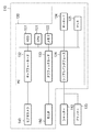
図2は上記画像処理装置110の基本構成と共に、シャッター160、プリンタ170との関係を示すブロック図である。画像処理装置110は大まかには上述の通り、PC120、ビデオカメラ140、モニタ150に大別される。
【0024】
PC120はキャプチャカード132,グラフィックカード130、シリアルI/F126,HDD123,CPU121、メモリ122、キーボード124、マウス125により構成されている。
【0025】
キャプチャカード132はPC120とビデオカメラ140とを接続するためのインターフェースとして機能し、ビデオカメラ140により撮像された各フレームの現実空間の画像がキャプチャカード132を介してメモリ122に転送される。
【0026】
グラフィックカード130は上記仮想物体の画像である3次元コンピュータグラフィックス(3DCG)を生成する機能を有する。
【0027】
シリアルI/F126は、PC120と後述のシャッター160、プリンタ170とを接続するためのインターフェースとして機能し、シリアルI/F126を介してPC120にシャッター160からボタンが押下されたことを示す信号が入力されたり、シリアルI/F126を介してPC120からプリンタ170に対してプリント対象の複合現実空間画像を送信したりすることができる。
【0028】
HDD123はPC120全体の制御を行うためのプログラムやデータ、プリンタ170を制御するためのプリンタドライバ、上記仮想空間管理プログラムや複合現実空間画像生成プログラム、各仮想物体の位置、形状など、仮想物体の画像を生成するために必要なデータ群、仮想空間の状態を示すデータ等を保存しており、これらのプログラムやデータは必要に応じてCPU121によりメモリ122にロードされる。
【0029】
CPU121はメモリ122にロードされたプログラムを実行したり、メモリ122にロードされたデータを参照することで、PC120の各部の制御を行い、複合現実空間画像を生成したり、PC120全体の制御を行うことができる。メモリ122は読み書き可能なメモリであって、CPU121の実行対象であるHDD123からロードされたプログラムやその際に使用するデータを一時的に記憶するエリアを備えると共に、CPU121が各処理を行う際に用いるワークエリアも備える。もちろん上述の通り、仮想空間の画像と現実空間画像とが重畳された画像である複合現実空間画像を描画するためのエリアも備える。
【0030】
キーボード124、マウス125はCPU121に対して各指示を入力するためのポインティングデバイスとして用いられ、例えば仮想物体の配置位置や仮想空間の状態設定などを入力するために用いられる。
【0031】
上述の通り、キャプチャカード132にはビデオカメラ140が接続されており、ビデオカメラ140は上述の通り、現実空間の動画像を撮像し、撮像した各フレームの画像はキャプチャカード132を介してメモリ122に出力する。
【0032】
また上述の通りグラフィックカード130にはモニタ150が接続されており、モニタ160はCRTや液晶画面などにより構成されており、グラフィックカード130により生成された3DCGを表示すると共に、それに重畳されたビデオカメラ140により撮像された現実空間の動画像も表示する。すなわち、複合現実空間画像を表示する。また上述の通り、モニタ150は複合現実空間画像だけでなく、PC120を操作する際に必要な情報(システムメッセージやシステムの設定画面など)を表示する。
【0033】
上記構成を備えるPC120が上記仮想空間管理プログラムを実行することで行う処理について、同処理のフローチャートを示す図3を用いて説明する。
【0034】
まず、キーボード124やマウス125等を用いて入力される仮想空間の状態情報(例えば、仮想物体の数や、種類、仮想空間内の光の強弱や色、天候など)に応じて、CPU121はメモリ122に記憶されている仮想空間の状態を示すデータを更新する(ステップS302)。なお、本ステップでは、経過する時間に従って仮想空間管理プログラムが仮想空間の状態を示すデータを逐次、もしくは所定時間毎に更新しても良い。
【0035】
次にCPU121は、更新した仮想空間の状態を示すデータを複合現実空間画像生成プログラムに通知する(ステップS304)。具体的には、このデータをメモリ122に記憶させると共に、複合現実空間画像生成プログラムを動作させる。そして、更新が終了したのであれば、本処理を終了する。
【0036】
次に、上記構成を備えるPC120が上記複合現実空間画像生成プログラムを実行することで行う処理について、同処理のフローチャートを示す図4を用いて説明する。
【0037】
CPU121は、メモリ122に記憶されている仮想空間の状態を示すデータを読み取り(ステップS702)、グラフィックカード130に仮想空間画像の描画指示を送ると、グラフィックカード130はこの状態を示すデータと、HDD123からメモリ122にロードされた3DCGのデータ、そしてビデオカメラ140の位置姿勢を示すデータとを用いて、ビデオカメラ140位置姿勢に従った仮想空間画像を生成する(ステップS704)。すなわち、メモリ122上に仮想空間画像を描画する。
【0038】
続いて、画像キャプチャスレッド(ステップS730)から継続的に送信されてきている、ビデオカメラ140によって撮像された現実空間画像を取得する(ステップS706)。ここで本プログラムは並列プログラミング技術の一つであるスレッドを応用して実装され、常に最新の現実空間画像を取得するようになっている。続いてグラフィックカード130は、取得された現実空間画像をメモリ122上に描画された仮想空間画像に重畳し、メモリ122上に複合現実空間画像を生成した後、モニタ150に出力する(ステップS708)。
【0039】
ここでCPU121がシャッター160から、ボタンが押下されたことを示す信号を検知した場合、処理をステップS712に進め、この時点でメモリ122上に描画された複合現実空間画像をメモリ122上の複合現実空間画像を、描画したエリアとは別のエリアにコピーし(ステップS712)、画像出力スレッドに、コピーした複合現実空間画像のデータが記憶されているメモリ122上の位置(アドレス)を指示する(ステップS714)。
【0040】
画像出力スレッドは指示されたアドレスに記憶されている上記複合現実空間画像のデータを取得し、取得したデータをプリンタ170に出力する(ステップS740)。その結果プリンタ170は、紙やOHPなどの記録媒体上に複合現実空間画像をプリントする。
【0041】
なおビデオカメラ140の設置位置および方向は座標軸220によって決まる座標値および姿勢値によって表現され、予め測定されており、上記複合現実空間画像生成プログラムの初期値として設定されている(上述の通り、メモリ122にデータとして記憶されている)。取得する複合現実空間画像の視点位置、姿勢(ビデオカメラ140の設置位置および設置姿勢)を変更したい場合は、その度に座標軸220におけるビデオカメラ140の位置および方向を実測し、初期設定を変更してやればよい。
【0042】
以上の説明により、本実施形態におけるシステムによって、任意の視点における複合現実空間画像を、紙やOHPなどの記録媒体によって取得することができる。
【0043】
[第2の実施形態]
第1の実施形態に係るシステムは、一人の観察者に対してのみ、複合現実空間画像を取得可能にしていた。本実施形態に係るシステムでは複数の観察者に対して、夫々の観察者で異なる視点に基づいた複合現実空間画像を取得可能にする。以下、本実施形態に係るシステムについて説明する。
【0044】
図5に本実施形態に係るシステムの構成を示す。同図において図1と同じ部分については同じ番号を付けており、その説明を省略する。観察者100と観察者500の夫々に対して複合現実空間画像を取得可能にする構成は第1の実施形態と同様である。すなわち観察者100に対して設けられたシステム(ビデオカメラ140とモニタ150とPC120とを含む画像処理装置110、プリンタ170、シャッター160からなるシステム)と同じシステム(ビデオカメラ540とモニタ550とPC520とを含む画像処理装置510、プリンタ570、シャッター560からなるシステム)が観察者500に対して設けられている。そして夫々の観察者に対して設けられたPC同士はLANやインターネットなどのネットワーク180を介して接続されている。
【0045】
また、本実施形態に係るシステムでは、仮想空間管理プログラムは夫々の観察者に対して設けられたPC上で動作するのではなく、上記ネットワーク180に接続された画像処理装置112上で動作する。よって画像処理装置112は第1の実施形態で説明したように仮想空間の状態を更新し、夫々のPC120,520は画像処理装置112上で動作する仮想空間管理プログラムによって更新された結果をネットワーク180を介して取得し、これを用いて夫々のPCに接続されたビデオカメラ140,540の位置姿勢に応じた仮想空間の画像を生成する。
【0046】
このようにすることで、夫々のPCで生成される複合現実感画像は、同じ複合現実空間を共有しながらも、夫々で異なる視点位置姿勢によるものとなる。
【0047】
図6は上記画像処理装置510の基本構成と共に、シャッター560、プリンタ570との関係を示すブロック図である。基本的には図2に示した構成と同じものであるが、PC520を上記ネットワーク180に接続するためのネットワークI/F127を更に設けた点が異なる。このネットワークI/F127を介して、画像処理装置112上で動作する仮想空間管理プログラムによって更新された結果を示すデータを受信することができる。
【0048】
なお、図6に示した構成は観察者100に対して設けられたシステムの構成として示したが、観察者500に対して設けられたシステムの構成も同様のものであることは上述の通りである。
【0049】
図7に上記画像処理装置112の構成を示す。画像処理装置112の構成は上記画像処理装置510から、ビデオカメラ、シャッター、プリンタを省いた構成である。図7において図1と同じ部分については同じ番号を付けており、その説明を省略する。
【0050】
また、画像処理装置112が行う処理は、図3に示したフローチャートに従った処理となる。また、PC120、150が行う処理は、図4に示したフローチャートに従った処理となる。
【0051】
また、夫々の観察者に対して設けたシステムの数を2のみでなく、それ以上に増やすことで、より多くの観察者に対して複合現実空間画像を取得可能にすることができる。
【0052】
以上の説明により、本実施形態に係るシステムによって、複数の観察者に対して、夫々異なる視点位置姿勢に応じた複合現実空間の画像を紙やOHPなどの記録媒体によって取得可能にすることができる。
【0053】
また複数の観察者が同時に同じ複合現実空間を観察することが可能になるばかりでなく、シャッター、プリンターを各観察者に対して設けたシステムに設けたことにより、各観察者が同時に複合現実空間画像を紙やOHPなどの記録媒体によって取得することが可能になった。
【0054】
[第3の実施形態]
本実施形態に係るシステムは、第2の実施形態で説明したシステムにおいて、任意の観察者に対して、モニタ160を介してではなく、撮像装置付の頭部搭載型表示装置(HMD)400を介して複合現実空間画像を提示する構成を備える。
【0055】
図8に本実施形態に係るシステムの構成を示す。同図において第2の実施形態に係るシステムの構成を示す図5と同じ部分については同じ番号を付けており、その説明を省略する。本実施形態では観察者100に対しては第2の実施形態と同様の構成及び方法を用いて複合現実空間画像を提示し、観察者500に対してHMD400を用いて複合現実空間画像を提示する例を示す。以下、観察者500に対して複合現実空間画像を提示するためのシステム(PC520とモニタ550と分配器600とHMD400を含む画像処理装置、シャッター560、プリンタ570、センサ系(300乃至320)からなるシステム)について説明する。
【0056】
観察者500の頭部にはHMD400が装着され、観察者500の視点位置近傍の上記座標軸200における位置、姿勢に応じた現実空間を上記撮像装置により撮像し、撮像した現実空間画像をPC520に送る。観察者500の視点の位置、姿勢は位置姿勢センサ系を構成する300乃至320によって常時計測されており、計測された結果は画像処理装置112に送られ、管理される。
【0057】
PC520は画像処理装置112で管理されている観察者500の視点の位置姿勢を取得し、同様に取得した仮想空間の状態情報と観察者500の視点の位置姿勢に応じた仮想空間画像を生成すると共に、HMD400から送られてきた現実空間画像と重畳して複合現実空間画像を生成する。
【0058】
生成された複合現実空間画像は分配器600を介してモニタ550に出力されると共に、HMD400に設けられた後述の表示部に出力され、夫々で表示される。これはHMD400ではPC520の操作用の表示装置としては不自由な点があるためと、HMD400を装着している観察者がどのような画像を見ているのかを観察者以外の者が知るためである。
【0059】
これにより、観察者500は自由に視点位置、姿勢を変えて、すなわち複合現実空間内を自由に動いて、その時々の視点位置姿勢に応じた複合現実空間画像を観察することができる。
【0060】
HMD400の構成について図9〜11を用いて説明する。なお各図において番号の後に「R」とつくものは観察者の右目用、「L」とつくものは左目用を表す。特に特定する必要のない場合、文中ではR、Lを省略して表記することにする。
【0061】
図9はHMDの基本構成を示す図、図10,11はHMD400の外観図である。320は位置方向センサ受信機で、観察者の視点位置近傍に設けられており、後述する位置姿勢センサ発信機310、本体300と共に動作し、観察者の視点位置および姿勢を常時計測している。
【0062】
410,414,415は夫々表示系を構成しており、カラー液晶ディスプレイ414が表示する画像が光学プリズム415によって導かれ、表示部410に表示される。412、416、417は撮像系を構成しており、入力部412を介してHMDの外部から入力された光が光学プリズム417によってHMD内部に導かれ、CCD416で受光される。光学プリズム415の出力光と光学プリズム417の入力光は観察者の瞳の光軸と一致しており、CCD416は観察者の視点位置、姿勢の現実空間画像を撮影し、カラー液晶ディスプレイ414はCCD416によって取得された現実空間画像と、位置姿勢センサ本体300で算出される観察者の視点位置、姿勢に応じてPC520で生成された仮想空間画像とをPC520により合成した複合現実空間画像を表示する。
【0063】
421〜425は頭部装着用の構成部材である。HMD400を頭部に装着するには、まず、アジャスタ422で長さ調整部423を緩めた状態で頭にかぶる。そして、額装着部425を額に密着させてから側頭装着部421と後頭装着部424を各々側頭部、後頭部に密着させるように、アジャスタ422で長さ調整部423を絞める。426はカラー液晶ディスプレイ414、CCD416、位置姿勢センサ受信機320のための電源および信号線をまとめたものである。
【0064】
次に観察者の視点位置、姿勢の計測方法について説明する。図8に示されているようにセンサ系(位置姿勢取得装置)は位置姿勢センサ本体300、位置姿勢センサ発信機310、位置姿勢センサ受信機320により構成されている。位置姿勢センサ受信機320、位置姿勢センサ発信機310は位置姿勢センサ本体300に接続されている。位置姿勢センサ発信機310からは磁気が発信されており、位置姿勢センサ受信機320がこの磁気を受信する。位置姿勢センサ本体300は位置姿勢センサ受信機320が受信した磁気の強度から位置姿勢センサ受信機320の上記座標軸200における位置、姿勢を公知の技術を用いて算出する。算出した結果は画像処理装置112に送られる。
【0065】
位置姿勢センサ受信機320はHMD400に固定されているため、位置姿勢センサ320とHMD400を装着した観察者100の入射瞳との相対的位置は定数となる。この定数と位置姿勢センサ受信機320の位置姿勢から観察者100の入射瞳の位置を計算することができる。本実施例では観察者100の入射瞳の位置を観察者100の視点位置として利用する。
【0066】
また、HMD400は観察者100が正面に自然に瞳を向けた時に正しく画像が観察可能であるよう観察者100に装着されている。よって、観察者がHMD400に表示される画像を観察するとき、位置姿勢センサ受信機320の方向と観察者100の視線方向は定数となる。この定数と位置姿勢センサ受信機320の位置姿勢から、HMD400の画像を観察している観察者100の視線方向を計算することができる。
【0067】
これら定数は予め測定されシステムに記憶されている。
【0068】
本実施形態では位置姿勢取得装置として米国Polhemus社製FASTRAKや米国Ascension Technology社製Flock of Birdsなどを利用することを仮定しているが、これに限定されるものではなく他の市販されている超音波式、光学式位置姿勢センサも利用可能である。
【0069】
以上説明したHMD400と位置姿勢計測装置を利用することで、観察者500は自由に視点位置、姿勢を任意に変更することができると共に、変更した視点位置、姿勢に応じた複合現実空間画像をHMD400を介して観察することができる。
【0070】
図12は上記画像処理装置1210、HMD400の基本構成と共に、シャッター560、プリンタ570との関係を示すブロック図である。図6、9と同じ部分については同じ番号を付けており、その説明を省略する。ただし、キャプチャカード132にはHMD400を構成するCCD416Rが接続されており、グラフィックカード130には分配器600が接続されている。また分配器600はカラー液晶ディスプレイ414L、414Rの夫々に接続されている。分配器600はPC520で生成された複合現実空間画像をHMD400とモニター550に分配する処理を行う。
【0071】
図13は画像処理装置112の基本構成を示すと共に、画像処理装置112と周辺機器との関係を示す図である。図7,8と同じ部分については同じ番号を付けており、その説明を省略する。画像処理装置112の基本構成については図7に示す画像処理装置と同じであるが、本実施形態に係る画像処理装置112のシリアルインターフェース126には上述の位置姿勢センサ本体300が接続されており、位置姿勢センサ本体300が位置姿勢センサ送信機310と位置姿勢センサ受信機320とにより得られる磁気の強度に基づいて求めた位置姿勢センサ受信機320の上記座標軸200における位置、姿勢を、シリアルインターフェース126を介して画像処理装置112に送る。
【0072】
画像処理装置112は送られた位置姿勢センサ受信機320の上記座標軸200における位置、姿勢のデータを、仮想空間の状態情報と共にメモリ122やHDD123に記憶し、管理する。
【0073】
また画像処理装置112では、仮想空間管理プログラムが動作していると共に、位置姿勢取得プログラムが動作している。画像処理装置112は位置姿勢取得プログラムを動作させることで、位置姿勢センサ本体300を制御し、接続されている位置姿勢センサ受信機320の搭載されているHMD400を装着している観察者の視点位置、視線方向を計測し、仮想空間管理プログラムに送信する処理を行う。
【0074】
次に、画像処理装置112が上記仮想空間管理プログラムを実行することで行う処理について、同処理のフローチャートを示す図14を用いて説明する。
【0075】
まず位置姿勢取得プログラムから、現実空間状態情報(観察者の視点の位置姿勢を示すデータ)を受信する(ステップS1402)。そして次に仮想空間の状態情報を更新する処理を行うが(ステップS1404)、これに関しては第1の実施形態におけるステップS302と同じ処理であるのでその説明を省略する。そして、現実空間状態情報、仮想空間状態情報をPC520で動作する複合現実空間画像生成プログラムに通知する(ステップS1406,1408)。具体的には、現実空間状態情報、仮想空間状態情報をネットワーク180を介してPC520で動作する複合現実空間画像生成プログラムに通知する。
【0076】
次に、PC520が上記複合現実空間画像生成プログラムを実行することで行う処理について、同処理のフローチャートを示す図15を用いて説明する。まず、上記仮想空間管理プログラムから通知された仮想空間状態情報、現実空間状態情報を受信する(ステップS1502,ステップS1503)。そしてステップS704と同様に仮想空間状態情報を用いて仮想空間画像を(ステップS1504)生成する。また、ステップS704と同様の画像キャプチャスレッド(ステップS1530)から継続的に送信されてきている、HMD400によって撮像された現実空間画像を取得する(ステップS1506)。そしてグラフィックカード130は、取得された現実空間画像をメモリ122上に描画された仮想空間画像に重畳し、メモリ122上に複合現実空間画像を生成した後、HMD400に出力する(ステップS1508)。以降処理については図7に示したステップS710以降の各ステップと同じであるのでその説明を省略する。
【0077】
以上の説明により、本実施形態に係るシステムによって、任意の視点位置、姿勢に応じた複合現実空間の画像を紙やOHPなどの記録媒体によって取得可能にすることができる。
【0078】
なお本実施形態では一人の観察者のみにHMDを用いたシステムを提供していたが、複数の観察者に対して設けても良い。この場合、夫々の観察者に対してPC、モニタ、プリンタ、分配器、HMD、センサ系を設け、画像処理装置112で動作する位置姿勢取得プログラムは、夫々のセンサ系から夫々の観察者の視点位置、姿勢を取得、管理し、必要に応じて夫々のPCに観察者の視点の位置、姿勢のデータを送信する。
【0079】
[第4の実施形態]
本実施形態に係るシステムは、現実空間を撮像する装置として、望遠鏡型撮像装置を用いる。図16に本実施形態に係るシステムの構成を示す。同図において第2の実施形態に係るシステムの構成を示す図5と同じ部分については同じ番号を付けており、その説明を省略する。本実施形態では観察者100に対しては第2の実施形態と同様の構成及び方法を用いて複合現実空間画像を提示し、観察者500に対して望遠鏡型撮像装置1600を用いて複合現実空間画像を提示する例を示す。以下、観察者1600に対して複合現実空間画像を提示するためのシステム(PC520とモニタ550と分配器600と望遠鏡型撮像装置1600を含む画像処理装置、シャッター560、プリンタ570からなるシステム)について説明する。
【0080】
望遠鏡型撮像装置1600は地面に固定された支柱1690に、同図矢印方向に回転可能なように取り付けられている。また、望遠鏡型撮像装置1600における取り付け部には、望遠鏡型撮像装置1600の向き(姿勢)を計測するための姿勢計測装置(ジャイロ)1620が備わっている。ジャイロ1620をこの部分に取り付ける理由としては、この部分を観察者の視点位置とするためである。他の部分を観察者の視点の位置とすると、望遠鏡型撮像装置1600の回転により、視点位置が変化してしまうからである。ジャイロ1620は視点の姿勢を計測するものであるから、上述の位置に取り付ける必要がある。ジャイロ1620により計測された視点の姿勢を示すデータはPC520に送られる。
【0081】
また視点位置(ジャイロ1620を取り付けた位置近傍の位置)には小型撮像装置(小型ビデオカメラ)1610が取り付けられ、現実空間の動画像を撮像する。撮像した現実空間の画像はPC1640に送られる。
【0082】
望遠鏡型撮像装置1600には小型表示装置1630が取り付けられており、小型表示装置1630には、小型撮像装置1610により撮像された現実空間画像とジャイロ1620により計測された視点の姿勢のデータをPC520に送ることでPC1640で生成され、分配器600を介して送られてくる複合現実空間画像が表示される。
【0083】
図17は上記PC520、望遠鏡型撮像装置1600の基本構成と共に、シャッター560、プリンタ570との関係を示すブロック図である。図6、12と同じ部分については同じ番号を付けており、その説明を省略する。ただし、キャプチャカード132には望遠鏡型撮像装置1600を構成する小型撮像装置1610が接続されており、グラフィックカード130には分配器600が接続されている。また分配器600は小型表示装置1630に接続されている。分配器600はPC520で生成された複合現実空間画像を小型表示装置1630とモニタ550に分配する処理を行う。
【0084】
一方、画像処理装置112の構成、及び画像処理装置112が行う処理については第2の実施形態と同じであるので、その説明を省略する。
【0085】
本実施形態における画像処理装置112では仮想空間管理プログラムが動作しており、PC520では位置姿勢取得プログラム、複合現実空間画像生成プログラムが動作している。
【0086】
画像処理装置112が仮想空間管理プログラムを動作させることで行う処理のフローチャートは図14に示したフローチャートにおいて、ステップS1402で後述の位置姿勢取得プログラムによって通知された視点の姿勢を受信する以外は同じフローチャートである。
【0087】
PC520は位置姿勢取得プログラムを動作させることで、ジャイロ1620を制御し、視線の姿勢を計測し、上記仮想空間管理プログラムに送信する。なお視点位置は、座標軸200における望遠鏡型撮像装置1600の回転軸の位置、小型表示装置の入射瞳の位置、望遠鏡型撮像装置1600の姿勢から計算で求めることが可能である。座標軸200における望遠鏡型撮像装置1600の回転軸の位置、小型表示装置の入射瞳の位置は予めシステム(メモリ122、HDD123など)に記憶されているものとする。
【0088】
また、PC520が上記複合現実空間画像生成プログラムを実行することで行う処理のフローチャートは図15において、ステップS1503で、上記仮想空間管理プログラムによって通知された視点の姿勢を示すデータを現実空間状態情報として受信する処理を行う点以外は同じである。
【0089】
以上の説明により、本実施形態に係るシステムにより、現実空間を撮像する装置と複合現実空間画像を表示する装置とを身につける手間がかからず、視点の任意の姿勢に応じた複合現実空間の画像を紙やOHPなどの記録媒体によって取得可能にすることができる。
【0090】
なお本実施形態では一人の観察者のみに望遠鏡型撮像装置を用いたシステムを提供していたが、複数の観察者に対して設けても良い。この場合、夫々の観察者に対してPC、モニタ、プリンタ、分配器、望遠鏡型撮像装置、ジャイロを設け、画像処理装置112で動作する仮想空間管理プログラムは、夫々のセンサ系から夫々の観察者の視点姿勢を取得、管理し、必要に応じて夫々のPCに観察者の視点の姿勢のデータを送信する。
【0091】
[第5の実施形態]
本実施形態に係るシステムの構成は基本的には第3の実施形態に係るシステムの構成と同じであるが、観察者500に対して提示するためのHMDの表示部に表示する複合現実画像を、立体画像として観察者500に対して提供する点が異なる。以下、本実施形態に係るシステムについて説明する。なおHMDとしては図9乃至11に示したものを用いるとする。
【0092】
HMD400の右目用表示部410Rに表示される複合現実空間画像と左目用表示部410Lに表示される複合現実空間画像を独立に生成することで、HMD400を装着している観察者は複合現実空間画像を立体画像として観察することができる。
【0093】
図18は観察者に対して複合現実空間画像を立体画像として提供するための画像処理装置1810の基本構成とシャッター560、プリンタ570との関係を示す図である。図12と同じ部分については同じ番号を付けており、その説明を省略する。本実施形態に係る画像処理装置1810を構成するPC1800にはキャプチャカード、グラフィックカードは夫々右目用、左目用に設けられている。すなわち右目用、左目用のキャプチャカード132R、132Lは夫々HMD400の右目用、左目用のCCD416R、416Lにと接続しており、右目用のCCD416Rにより撮像された現実空間の画像は右目用キャプチャカード132Rを介してメモリ122に、左目用のCCD416Lにより撮像された現実空間の画像は左目用キャプチャカード132Lを介してメモリ122に、夫々送られる。
【0094】
PC1800では第3の実施形態で説明した複合現実空間画像の生成処理を左目用、右目用に行い、右目用複合現実空間画像、左目用複合現実空間画像を生成する。生成された右目用複合現実空間画像は右目用グラフィックカード130R、分配器600を介して右目用のカラー液晶ディスプレイ414Rとモニタ550に、生成された左目用複合現実空間画像は左目用グラフィックカード130Lを介して左目用のカラー液晶ディスプレイ414Lに夫々出力される。これにより、HMD400を装着した観察者の左目と右目とに対して、夫々独立した複合現実空間画像を提示することができる。
【0095】
なお、モニタ550に表示する複合現実空間画像は右目用複合現実空間画像に限らず、左目用の複合現実空間画像でも良い。その場合、分配器600を左目用グラフィックカード130Lとカラー液晶ディスプレイ414Lとの間に設ければよい。
【0096】
次に、右目用、左目用の複合現実空間画像を生成する処理について以下、説明する。この処理はPC1800により複合現実空間画像生成プログラムを動作させることで行うが、複合現実空間映像生成プログラムは右目用と左目用の2つがメモリ122に記憶されており、PC1800は夫々を独立して並列に動作させる。また、本実施形態ではセンサ系により得られる視点の位置、姿勢は、同じ座標軸における右目の位置と視線方向とするので、左目の同座標軸における位置と視線方向を求める処理が必要となる。
【0097】
PC1800が上記複合現実空間画像生成プログラムを実行することで行う処理のフローチャートを図19に示す。同図のフローチャートは図15に示したフローチャートに更にステップS1530、S1532を加えたものであるが、これらのステップによる処理は上述の通り、左目の位置を求める処理である。なお、左目の視線方向は計測した右目の視線方向と同じものであると仮定する。
【0098】
ステップS1530で、処理が左目用のものである場合には処理をステップS1532に進め、右目の位置から観察者の両目の間隔だけずらした位置を左目の位置として求める。なお、観察者の両目の間隔は予め求めておき、メモリ122、もしくはHDD123に記憶させておく。
【0099】
また、ステップS1510以降処理については2つの複合現実空間画像生成プログラムのうち、何れかのプログラムを動作させればよい。
【0100】
以上の説明により、本実施形態に係るシステムによって、観察者に対して複合現実空間画像を立体画像として提示することができる。これにより、観察者はより的確に複合現実空間を観察することができるので、取得したい複合現実空間の領域をより的確に決めることができ、決めた領域の複合現実空間画像を紙やOHPなどの記録媒体によって取得可能にすることができる。
【0101】
なお本実施形態では一人の観察者のみにHMDを用いたシステムを提供していたが、複数の観察者に対して設けても良い。この場合、夫々の観察者に対してPC、モニタ、プリンタ、分配器、HMD、センサ系を設け、画像処理装置112で動作する位置姿勢取得プログラムは、夫々のセンサ系から夫々の観察者の視点位置、姿勢を取得、管理し、必要に応じて夫々のPCに観察者の視点の位置、姿勢のデータを送信する。
【0102】
[第6の実施形態]
本実施形態に係るシステムは上記各実施形態と同様に複数の観察者に対して複合現実空間画像を提示するが、特定の観察者のみが他の観察者が観察している複合現実空間画像のうち、特定の画像を選択し、プリンタに出力させることができる。以下、本実施形態に係るシステムについて説明する。
【0103】
図20は本実施形態に係るシステムの構成を示す図である。同図において第3の実施形態で用いた図8と同じ部分には同じ番号を付けており、その説明を省略する。図20では上記特定の観察者、すなわち複合現実空間画像を取得する観察者(複合現実空間画像取得者)は102で示されており、その他の観察者2001,2002は複合現実空間画像の取得操作、すなわちシャッターを押下する操作は行わずに、複合現実空間画像の観察のみを行う。
【0104】
観察者2001,2002に対して夫々複合現実空間画像を提示するためのシステムの構成は第3の実施形態で説明したものと同じものである。そこで以下では、観察者102が他の観察者(同図では観察者2001,2002)が観察している複合現実空間画像をプリンタ170を用いてプリントするためのシステムについて説明する。
【0105】
観察者102は第1の実施形態と同様に手にはシャッター160を持っており、このシャッター160を押下することで上記実施形態で説明したように、画像処理装置114のメモリに格納された複合現実空間画像データをプリンタ170に出力する。画像処理装置114のメモリに格納される複合現実空間画像データは、観察者102以外の観察者に対して複合現実空間画像を提示する夫々の画像処理装置のうち、切り替え器2000によって選択された画像処理装置により生成される複合現実空間画像のデータである。
【0106】
図21に画像処理装置114の基本構成と、切り替え器2000、そしてシャッター160、プリンタ170との関係を示す。なお、図2,6と同じ部分については同じ番号を付けており、その説明を省略する。
【0107】
複合現実空間画像取得者102がシャッター160のボタンを押下することにより、CPU121は切り替え器2000によって選択されている画像処理装置に対して、この画像処理装置のメモリに上記押下時(実際にはタイムディレイが生じるが)に格納されている複合現実空間画像データを画像処理装置114に送信するように指示する。指示された画像処理装置は、生成した複合現実空間画像データを切り替え器2000を介して画像処理装置114に送信し、送信された複合現実空間画像はグラフィックカード130を介してメモリ122に格納される。これにより画像処理装置114では切り替え器2000によって選択された画像処理装置により生成された複合現実空間画像データ(言い換えれば、複合現実空間画像取得者以外の観察者に対して提示されている複合現実空間画像のうち、選択された複合現実空間画像のデータ)を得ることができるので、上述の実施形態と同様に、メモリ122に格納されたこの画像のデータをプリンタ170に出力することができる。
【0108】
なお、切り替え器2000の制御、すなわち、どの画像処理装置から複合現実空間画像を送信してもらうかの制御は、キーボード124やマウス125を用いて、モニタ154の表示画面上に表示される不図示のGUIなどを用いて設定する。
【0109】
また、切り替え器2000にはモニタ154も接続されており、切り替え器2000によって選択された画像処理装置により生成された複合現実空間画像は切り替え器を介してモニタ154に出力されるので、モニタ154にはこの複合現実空間画像を表示することができる。モニタ154に表示することによって、複合現実空間画像取得者102はどの画像処理装置で生成された複合現実空間画像をプリンタ170に出力するかを選択する(切り替え器2000を制御する)ことができる。
【0110】
複合現実空間画像取得者102以外の観察者に対して複合現実空間画像を提示する画像処理装置では第3の実施形態の通り複合現実空間画像生成プログラムが動作しており、画像処理装置112では第3の実施形態の通り、位置姿勢取得プログラムと仮想空間管理プログラムが動作している。夫々のプログラムの動作については第3の実施形態の説明の通りである。
【0111】
以上の説明により、本実施形態におけるシステムによって、複数の観察者による任意の視点における夫々の複合現実空間画像のうち、1つを選択して、紙やOHPなどの記録媒体によって取得することができる。
【0112】
なお本実施形態に係るシステムでは複合現実空間画像取得者に対する画像処理装置、プリンタは夫々1つずつであったがが、複数であっても良い。また、プリンタはネットワーク180に接続されているどの画像処理装置に接続されていても構わない。
【0113】
[第7の実施形態]
第6の実施形態に係るシステムでは、複合現実空間画像取得者以外の観察者に対して提示されている複合現実空間画像のうち、1つを選択し、選択した画像のみをプリントの対象としていたが、本実施形態に係るシステムでは、1つ以上、すなわち複数の複合現実空間画像を選択することができ、選択した夫々の複合現実空間画像を縮小し、縮小した夫々の複合現実空間画像を含む画像を生成し、この画像をプリント対象とする。以下、本実施形態に係るシステムについて説明する。
【0114】
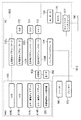
図22は本実施形態に係るシステムの構成を示す図である。基本的には第6の実施形態に係るシステムの構成(図20に示す構成)と同じであるが、本実施形態では切り替え器2000の代わりに、選択器2600、合成器2500が用いられている点以外は第6の実施形態に係るシステムと同じ構成である。よって以下ではこの選択器2600、合成器2500について説明する。
【0115】
選択器2600では複合現実空間画像取得者102以外の観察者に対して複合現実空間画像を提示する画像処理装置において任意の画像処理装置(1つ以上の画像処理装置)から複合現実空間画像を取得することができる。取得した複合現実空間画像は合成器2500に送られる。
【0116】
送られた複合現実空間画像が複数の場合、合成器2500では、夫々の画像を縮小し、縮小した夫々の画像を含む1つの画像(合成画像)を生成する。例えば合成器2500が4つの複合現実空間画像を得た場合、生成する合成画像は例えば図23に示すとおりとなる。図23は縮小した4つの複合現実空間画像の夫々を含む合成画像の例を示す図である。同図では画像処理装置1,2,3,4の夫々から得られた複合現実空間画像を縮小している。なお、各画像の配置順やレイアウトに関してはこれに限定されるものではない。なお、送られた複合現実空間画像が1つの場合にはこの処理を省略し、送られた画像を合成画像として以下扱う。合成器2500によって生成された合成画像はモニタ154に表示される共に、プリントの対象となる。
【0117】
図24に画像処理装置114の基本構成と、選択器2600、合成器2500、そしてシャッター160、プリンタ170との関係を示す。なお、図21と同じ部分については同じ番号を付けており、その説明を省略する。
【0118】
複合現実空間画像取得者102がシャッター160のボタンを押下することにより、CPU121は選択器2600によって選択されている画像処理装置に対して、この画像処理装置のメモリに上記押下時(実際にはタイムディレイが生じるが)に格納されている複合現実空間画像データを画像処理装置114に送信するように指示する。指示された画像処理装置は、生成した複合現実空間画像データを選択器2600を介して合成器2500に送信する。合成器2500では上述の通り、送信された複合現実空間画像を用いて1つの合成画像を生成し、生成した合成画像をメモリ122に送り、メモリ122はこの合成画像を記憶する。これにより画像処理装置114では選択器2600によって選択された画像処理装置により生成された複合現実空間画像データ(言い換えれば、複合現実空間画像取得者以外の観察者に対して提示されている複合現実空間画像のうち、選択された複合現実空間画像のデータ)を含む合成画像を得ることができるので、上述の実施形態と同様に、メモリ122に格納されたこの画像のデータをプリンタ170に出力することができる。
【0119】
なお、選択器2600の制御、すなわち、どの画像処理装置から複合現実空間画像を送信してもらうかの制御は、キーボード124やマウス125を用いて、モニタ154の表示画面上に表示される不図示のGUIなどを用いて設定する。
【0120】
また、合成画像合成器2500にはモニタ154も接続されており、選択器2600によって選択された画像処理装置により生成された複合現実空間画像を含む合成画像はモニタ154に出力されるので、モニタ154にはこの合成画像を表示することができる。モニタ154に表示することによって、複合現実空間画像取得者102はどの画像処理装置で生成された複合現実空間画像を合成画像に含めるかを選択する(選択器2600を制御する)ことができる。
【0121】
複合現実空間画像取得者102以外の観察者に対して複合現実空間画像を提示する画像処理装置では第3の実施形態の通り複合現実空間画像生成プログラムが動作しており、画像処理装置112では第3の実施形態の通り、位置姿勢取得プログラムと仮想空間管理プログラムが動作している。夫々のプログラムの動作については第3の実施形態の説明の通りである。
【0122】
以上の説明により、本実施形態におけるシステムによって、複数の観察者による任意の視点における夫々の複合現実空間画像のうち、複数を選択することができ、選択した複数の複合現実空間画像を、紙やOHPなどの記録媒体によって取得することができる。
【0123】
なお本実施形態に係るシステムでは複合現実空間画像取得者に対する画像処理装置、プリンタは夫々1つずつであったがが、複数であっても良い。また、プリンタはネットワーク180に接続されているどの画像処理装置に接続されていても構わない。
【0124】
[その他の実施の形態]
さらに、本発明は上記実施形態を実現するための装置及び方法のみに限定されるものではなく、上記システム又は装置内のコンピュータ(CPUあるいはMPU)に、上記実施形態を実現するためのソフトウエアのプログラムコードを供給し、このプログラムコードに従って上記システムあるいは装置のコンピュータが上記各種デバイスを動作させることにより上記実施形態を実現する場合も本発明の範疇に含まれる。
【0125】
またこの場合、前記ソフトウエアのプログラムコード自体が上記実施形態の機能を実現することになり、そのプログラムコード自体、及びそのプログラムコードをコンピュータに供給するための手段、具体的には上記プログラムコードを格納した記憶媒体は本発明の範疇に含まれる。
【0126】
この様なプログラムコードを格納する記憶媒体としては、例えばフロッピー(登録商標)ディスク、ハードディスク、光ディスク、光磁気ディスク、CD-ROM、磁気テープ、不揮発性のメモリカード、ROM等を用いることができる。
【0127】
また、上記コンピュータが、供給されたプログラムコードのみに従って各種デバイスを制御することにより、上記実施形態の機能が実現される場合だけではなく、上記プログラムコードがコンピュータ上で稼働しているOS(オペレーティングシステム)、あるいは他のアプリケーションソフト等と共同して上記実施形態が実現される場合にもかかるプログラムコードは本発明の範疇に含まれる。
【0128】
更に、この供給されたプログラムコードが、コンピュータの機能拡張ボードやコンピュータに接続された機能拡張ユニットに備わるメモリに格納された後、そのプログラムコードの指示に基づいてその機能拡張ボードや機能格納ユニットに備わるCPU等が実際の処理の一部または全部を行い、その処理によって上記実施形態が実現される場合も本発明の範疇に含まれる。
【0129】
【発明の効果】
以上の説明により、本発明によって、複合現実空間画像を取得することができる。
【図面の簡単な説明】
【図1】観察者と、この観察者に対して複合現実空間の画像を取得可能にする本発明の第1の実施形態に係るシステムの構成を示す図である。
【図2】上記画像処理装置110の基本構成と共に、シャッター160、プリンタ170との関係を示すブロック図である。
【図3】PC120が上記仮想空間管理プログラムを実行することで行う処理のフローチャートである。
【図4】PC120が上記複合現実空間画像生成プログラムを実行することで行う処理のフローチャートである。
【図5】本発明の第2の実施形態に係るシステムの構成を示す。
【図6】画像処理装置510の基本構成と共に、シャッター560、プリンタ570との関係を示すブロック図である。
【図7】画像処理装置112の構成を示す図である。
【図8】本発明の第3の実施形態に係るシステムの構成を示す図である。
【図9】HMDの基本構成を示す図である。
【図10】HMD400の外観図である。
【図11】HMD400の外観図である。
【図12】画像処理装置1210、HMD400の基本構成と共に、シャッター560、プリンタ570との関係を示すブロック図である。
【図13】画像処理装置112の基本構成を示すと共に、画像処理装置112と周辺機器との関係を示す図である。
【図14】画像処理装置112が仮想空間管理プログラムを実行することで行う処理のフローチャートである。
【図15】PC520が複合現実空間画像生成プログラムを実行することで行う処理のフローチャートである。
【図16】本発明の第4の実施形態に係るシステムの構成を示す図である。
【図17】PC520、望遠鏡型撮像装置1600の基本構成と共に、シャッター560、プリンタ570との関係を示すブロック図である。
【図18】観察者に対して複合現実空間画像を立体画像として提供するための画像処理装置1810の基本構成とシャッター560、プリンタ570との関係を示す図である。
【図19】PC1800が複合現実空間画像生成プログラムを実行することで行う処理のフローチャートである。
【図20】本発明の第6の実施形態に係るシステムの構成を示す図である。
【図21】画像処理装置114の基本構成と、切り替え器2000、そしてシャッター160、プリンタ170との関係を示す。
【図22】本発明の第7の実施形態に係るシステムの構成を示す図である。
【図23】縮小した4つの複合現実空間画像の夫々を含む合成画像の例を示す図である。
【図24】画像処理装置114の基本構成と、選択器2600、合成器2500、そしてシャッター160、プリンタ170との関係を示す。[0001]
BACKGROUND OF THE INVENTION
The present invention relates to an image processing apparatus and an image processing method for generating a mixed reality space image obtained by superimposing a real space image and a virtual space image.
[0002]
[Prior art]
It is possible to generate a mixed reality space image by superimposing a virtual object image generated in a computer on a real space image captured using an imaging device such as a camera capable of capturing still images and moving images. it can. Then, by displaying this image on the display screen of the display device, it can be presented to the user.
[0003]
In addition, when the user wants to acquire the mixed reality space image in some form, it is conventionally displayed on this screen by photographing the display screen using an imaging device such as a camera and printing it on electronic data or film. Had acquired images.
[0004]
[Problems to be solved by the invention]
However, in the above method, since the image displayed on the display device is captured, the image quality of the obtained image is poor, and the display device itself may be included in the image.
[0005]
In addition, it is almost impossible to shoot images of the mixed reality space in the viewpoint position and line-of-sight direction desired by the photographer, and obtain an interesting image that can understand how the observer and the virtual object interact with each other It was very difficult.
[0006]
The present invention has been made in view of the above problems, and an object thereof is to provide an image processing apparatus and an image processing method capable of acquiring a mixed reality space image.
[0007]
[Means for Solving the Problems]
In order to achieve the object of the present invention, for example, an image processing apparatus of the present invention comprises the following arrangement.
[0008]
That is, a generation unit that generates an image of a virtual space according to the position and orientation of the viewpoint in a coordinate system shared by the real space and the virtual space, with an imaging device that captures an image of the real space as a viewpoint in the virtual space And a compositing unit that synthesizes the image of the real space and the image of the virtual space to generate a mixed reality space image, and is capable of data communication with a plurality of external devices and connected to a printing unit An image processing apparatus comprising:
Selecting means for selecting two or more from the plurality of external devices;
An acquisition means for acquiring a mixed reality space image generated by the synthesis unit of each external device selected by the selection means;
Generating means for generating one image including each of the mixed reality space images by reducing and arranging the mixed reality space images acquired by the acquisition means;
Display means for displaying one image generated by the generating means;
Means for accepting print instructions;
When the print instruction is input, the mixed reality space image is requested to each external device selected by the selection unit, and transmitted from each external device selected by the selection unit in response to the request. The mixed reality space images are acquired, and the acquired mixed reality space images are reduced and arranged to generate one image including the mixed reality space images, and the generated one image is Output means for outputting to the printing means;
It is characterized by providing.
[0011]
In order to achieve the object of the present invention, for example, an image processing method of the present invention comprises the following arrangement.
[0012]
That is, a generation unit that generates an image of a virtual space according to the position and orientation of the viewpoint in a coordinate system shared by the real space and the virtual space, with an imaging device that captures an image of the real space as a viewpoint in the virtual space And a compositing unit that synthesizes the image of the real space and the image of the virtual space to generate a mixed reality space image, and is capable of data communication with a plurality of external devices and connected to a printing unit An image processing method performed by an image processing apparatus,
A selection step of selecting two or more from the plurality of external devices;
An acquisition step of acquiring a mixed reality space image generated by the synthesis unit of each external device selected in the selection step;
Generating a single image including each mixed reality space image by reducing and arranging the mixed reality space images acquired in the acquiring step;
A display step for displaying one image generated in the generation step;
Receiving a print instruction;
When the print instruction is input, a mixed reality space image is requested from each external device selected in the selection step, and transmitted from each external device selected in the selection step in response to the request. The mixed reality space images are acquired, and the acquired mixed reality space images are reduced and arranged to generate one image including the mixed reality space images, and the generated one image is An output process for outputting to the printing means;
It is characterized by providing.
[0015]
DETAILED DESCRIPTION OF THE INVENTION
Hereinafter, the present invention will be described in detail according to preferred embodiments with reference to the accompanying drawings.
[0016]
[First Embodiment]
FIG. 1 is a diagram illustrating the configuration of an observer and a system according to the present embodiment that enables the observer to acquire an image of the mixed reality space.
[0017]
The virtual space management program has a function of updating the state of the virtual space by being executed by the PC 120 and notifying the update result to the mixed reality space image generation program. The mixed reality space image generation program is executed by the PC 120, thereby rendering the virtual space image on the memory based on the state of the virtual space notified from the virtual space management program, and the real space image acquired from the
[0018]
The
[0019]
The
[0020]
The recording method of the
[0021]
[0022]
[0023]
FIG. 2 is a block diagram showing the basic configuration of the
[0024]
The
[0025]
The
[0026]
The
[0027]
The serial I /
[0028]
The
[0029]
The
[0030]
The
[0031]
As described above, the
[0032]
Further, as described above, the
[0033]
A process performed by the
[0034]
First, the
[0035]
Next, the
[0036]
Next, processing performed by the
[0037]
When the
[0038]
Subsequently, a real space image captured by the
[0039]
If the
[0040]
The image output thread acquires the mixed reality space image data stored at the instructed address, and outputs the acquired data to the printer 170 (step S740). As a result, the
[0041]
The installation position and direction of the
[0042]
As described above, the mixed reality space image at an arbitrary viewpoint can be acquired by a recording medium such as paper or OHP by the system in the present embodiment.
[0043]
[Second Embodiment]
The system according to the first embodiment makes it possible to acquire a mixed reality space image only for one observer. The system according to the present embodiment makes it possible to acquire a mixed reality space image based on different viewpoints for each observer for a plurality of observers. Hereinafter, the system according to the present embodiment will be described.
[0044]
FIG. 5 shows a configuration of a system according to the present embodiment. In the figure, the same parts as those in FIG. The configuration that makes it possible to acquire a mixed reality space image for each of the
[0045]
Further, in the system according to the present embodiment, the virtual space management program does not operate on the PC provided for each observer, but operates on the
[0046]
By doing so, the mixed reality images generated by the respective PCs are based on different viewpoint positions and postures while sharing the same mixed reality space.
[0047]
FIG. 6 is a block diagram showing the basic configuration of the
[0048]
The configuration shown in FIG. 6 is shown as the configuration of the system provided for the
[0049]
FIG. 7 shows the configuration of the
[0050]
The processing performed by the
[0051]
Further, by increasing the number of systems provided for each observer to not only two but more, it is possible to obtain a mixed reality space image for more observers.
[0052]
As described above, the system according to the present embodiment enables a plurality of observers to acquire mixed reality space images corresponding to different viewpoint positions and orientations using a recording medium such as paper or OHP. .
[0053]
In addition to allowing multiple observers to observe the same mixed reality space at the same time, by providing a system with a shutter and printer for each observer, each observer can simultaneously observe the mixed reality space. Images can be acquired by recording media such as paper and OHP.
[0054]
[Third Embodiment]
The system according to this embodiment is the same as the system described in the second embodiment except that a head mounted display device (HMD) 400 with an imaging device is used for an arbitrary observer, not via the
[0055]
FIG. 8 shows a system configuration according to the present embodiment. In this figure, the same parts as those in FIG. 5 showing the configuration of the system according to the second embodiment are given the same numbers, and the description thereof is omitted. In this embodiment, a mixed reality space image is presented to the
[0056]
An
[0057]
The
[0058]
The generated mixed reality space image is output to the
[0059]
Thus, the
[0060]
The configuration of the
[0061]
9 is a diagram showing the basic configuration of the HMD, and FIGS. 10 and 11 are external views of the
[0062]
Reference numerals 410, 414, and 415 each constitute a display system, and an image displayed on the color liquid crystal display 414 is guided by the optical prism 415 and displayed on the display unit 410. Reference numerals 412, 416, and 417 constitute an imaging system. Light input from the outside of the HMD via the input unit 412 is guided into the HMD by the optical prism 417 and received by the CCD 416. The output light of the optical prism 415 and the input light of the optical prism 417 coincide with the optical axis of the observer's pupil, the CCD 416 takes a real space image of the observer's viewpoint position and orientation, and the color liquid crystal display 414 is the CCD 416. The mixed real space image obtained by combining the virtual space image generated by the
[0063]
[0064]
Next, a method for measuring the observer's viewpoint position and orientation will be described. As shown in FIG. 8, the sensor system (position and orientation acquisition apparatus) includes a position and orientation sensor
[0065]
Since the position /
[0066]
The
[0067]
These constants are measured in advance and stored in the system.
[0068]
In this embodiment, it is assumed that FASTRAK manufactured by US Polhemus or Flock of Birds manufactured by US Ascension Technology is used as a position and orientation acquisition device, but the present invention is not limited to this, and other commercially available super Sonic and optical position and orientation sensors can also be used.
[0069]
By using the
[0070]
FIG. 12 is a block diagram showing the basic configuration of the
[0071]
FIG. 13 is a diagram illustrating a basic configuration of the
[0072]
The
[0073]
In the
[0074]
Next, processing performed by the
[0075]
First, real space state information (data indicating the position and orientation of the observer's viewpoint) is received from the position and orientation acquisition program (step S1402). Next, a process of updating the virtual space state information is performed (step S1404). Since this is the same process as step S302 in the first embodiment, the description thereof is omitted. Then, the real space state information and the virtual space state information are notified to the mixed reality space image generation program operating on the PC 520 (steps S1406 and 1408). Specifically, the real space state information and the virtual space state information are notified to the mixed reality space image generation program operating on the
[0076]
Next, processing performed by the
[0077]
As described above, the system according to the present embodiment makes it possible to acquire an image of the mixed reality space according to an arbitrary viewpoint position and orientation using a recording medium such as paper or OHP.
[0078]
In this embodiment, the system using the HMD is provided to only one observer, but it may be provided for a plurality of observers. In this case, each observer is provided with a PC, a monitor, a printer, a distributor, an HMD, and a sensor system, and the position / orientation acquisition program that operates on the
[0079]
[Fourth Embodiment]
The system according to the present embodiment uses a telescope-type imaging device as a device for imaging a real space. FIG. 16 shows the configuration of a system according to this embodiment. In this figure, the same parts as those in FIG. 5 showing the configuration of the system according to the second embodiment are given the same numbers, and the description thereof is omitted. In this embodiment, a mixed reality space image is presented to the
[0080]
The
[0081]
A small imaging device (small video camera) 1610 is attached to the viewpoint position (position in the vicinity of the position where the
[0082]
A
[0083]
FIG. 17 is a block diagram showing the relationship between the
[0084]
On the other hand, since the configuration of the
[0085]
In the
[0086]
The flowchart of the processing performed by the
[0087]
The
[0088]
In addition, in FIG. 15, the flowchart of the processing performed by the
[0089]
As described above, the system according to the present embodiment does not require the trouble of wearing the device that captures the real space and the device that displays the mixed reality space image, and the mixed reality space according to any viewpoint posture. These images can be acquired by a recording medium such as paper or OHP.
[0090]
In the present embodiment, the system using the telescopic imaging device is provided to only one observer, but it may be provided for a plurality of observers. In this case, each observer is provided with a PC, a monitor, a printer, a distributor, a telescope type imaging device, and a gyro, and the virtual space management program operating on the
[0091]
[Fifth Embodiment]
The configuration of the system according to the present embodiment is basically the same as the configuration of the system according to the third embodiment, but the mixed reality image displayed on the display unit of the HMD for presentation to the
[0092]
By independently generating the mixed reality space image displayed on the right-
[0093]
FIG. 18 is a diagram illustrating a relationship between a basic configuration of an
[0094]
The
[0095]
The mixed reality space image displayed on the
[0096]
Next, a process for generating mixed reality space images for the right eye and the left eye will be described below. This process is performed by operating the mixed reality space image generation program by the
[0097]
FIG. 19 shows a flowchart of processing performed by the
[0098]
If it is determined in step S1530 that the process is for the left eye, the process proceeds to step S1532, and a position shifted by the interval between the eyes of the observer from the position of the right eye is obtained as the position of the left eye. Note that the distance between the eyes of the observer is obtained in advance and stored in the
[0099]
In addition, for the processing after step S1510, one of the two mixed reality space image generation programs may be operated.
[0100]
As described above, the mixed reality space image can be presented as a stereoscopic image to the observer by the system according to the present embodiment. Thereby, since the observer can observe the mixed reality space more accurately, the region of the mixed reality space to be acquired can be determined more accurately, and the mixed reality space image of the determined region can be obtained by using paper or OHP. It can be made acquirable by a recording medium.
[0101]
In this embodiment, the system using the HMD is provided to only one observer, but it may be provided for a plurality of observers. In this case, each observer is provided with a PC, a monitor, a printer, a distributor, an HMD, and a sensor system, and the position / orientation acquisition program that operates on the
[0102]
[Sixth Embodiment]
The system according to the present embodiment presents a mixed reality space image to a plurality of observers as in the above embodiments, but only a specific observer observes a mixed reality space image that is observed by other observers. Of these, a specific image can be selected and output to a printer. Hereinafter, the system according to the present embodiment will be described.
[0103]
FIG. 20 is a diagram showing a configuration of a system according to the present embodiment. In this figure, the same parts as those in FIG. 8 used in the third embodiment are denoted by the same reference numerals, and the description thereof is omitted. In FIG. 20, the specific observer, that is, the observer who acquires the mixed reality space image (mixed reality space image acquirer) is indicated by 102, and the
[0104]
The system configuration for presenting the mixed reality space images to the
[0105]
As in the first embodiment, the
[0106]
FIG. 21 shows the relationship between the basic configuration of the
[0107]
When the mixed reality
[0108]
Note that the control of the
[0109]
A
[0110]
In the image processing apparatus that presents a mixed reality space image to an observer other than the mixed reality
[0111]
As described above, the system according to the present embodiment can select one of the mixed reality space images at arbitrary viewpoints by a plurality of observers and acquire the selected one by using a recording medium such as paper or OHP. .
[0112]
In the system according to the present embodiment, one image processing apparatus and one printer are provided for the mixed reality space image acquirer. However, a plurality of image processing apparatuses and printers may be provided. In addition, the printer may be connected to any image processing apparatus connected to the
[0113]
[Seventh Embodiment]
In the system according to the sixth embodiment, one of the mixed reality space images presented to the observer other than the mixed reality space image acquirer is selected, and only the selected image is the target of printing. However, in the system according to the present embodiment, one or more, that is, a plurality of mixed reality space images can be selected, each selected mixed reality space image is reduced, and each reduced mixed reality space image is included. An image is generated, and this image is to be printed. Hereinafter, the system according to the present embodiment will be described.
[0114]
FIG. 22 is a diagram showing a configuration of a system according to the present embodiment. The configuration is basically the same as that of the system according to the sixth embodiment (configuration shown in FIG. 20), but in this embodiment, a
[0115]
The
[0116]
When there are a plurality of mixed reality space images sent, the
[0117]
FIG. 24 shows the basic configuration of the
[0118]
When the mixed reality
[0119]
Note that control of the
[0120]
A
[0121]
In the image processing apparatus that presents a mixed reality space image to an observer other than the mixed reality
[0122]
As described above, the system according to the present embodiment can select a plurality of mixed reality space images at arbitrary viewpoints by a plurality of observers. It can be obtained by a recording medium such as OHP.
[0123]
In the system according to the present embodiment, one image processing apparatus and one printer are provided for the mixed reality space image acquirer. However, a plurality of image processing apparatuses and printers may be provided. In addition, the printer may be connected to any image processing apparatus connected to the
[0124]
[Other embodiments]
Furthermore, the present invention is not limited to only the apparatus and method for realizing the above-described embodiment, and the software for realizing the above-described embodiment is stored in a computer (CPU or MPU) in the system or apparatus. The case where the above embodiment is realized by supplying a program code and causing the computer of the system or apparatus to operate the various devices according to the program code is also included in the scope of the present invention.
[0125]
In this case, the program code of the software itself realizes the function of the above embodiment, and the program code itself and means for supplying the program code to the computer, specifically, the program code The stored storage medium is included in the category of the present invention.
[0126]
As a storage medium for storing such a program code, for example, a floppy (registered trademark) disk, a hard disk, an optical disk, a magneto-optical disk, a CD-ROM, a magnetic tape, a nonvolatile memory card, a ROM, or the like can be used.
[0127]
The computer controls various devices according to only the supplied program code so that the functions of the above-described embodiments are realized, and the OS (operating system) on which the program code is running on the computer is also provided. ), Or when the above embodiment is realized in cooperation with other application software or the like, the program code is also included in the scope of the present invention.
[0128]
Further, after the supplied program code is stored in the memory of the function expansion board of the computer or the function expansion unit connected to the computer, the program code is stored in the function expansion board or function storage unit based on the instruction of the program code. A case in which the CPU or the like provided performs part or all of the actual processing and the above-described embodiment is realized by the processing is also included in the scope of the present invention.
[0129]
【The invention's effect】
As described above, the mixed reality space image can be acquired by the present invention.
[Brief description of the drawings]
FIG. 1 is a diagram showing a configuration of a system according to a first embodiment of the present invention that enables an observer and an image of a mixed reality space to be acquired by the observer.
FIG. 2 is a block diagram showing the basic configuration of the
FIG. 3 is a flowchart of processing performed when the
FIG. 4 is a flowchart of processing performed when the
FIG. 5 shows a configuration of a system according to a second embodiment of the present invention.
FIG. 6 is a block diagram illustrating a relationship between a
7 is a diagram illustrating a configuration of an
FIG. 8 is a diagram showing a configuration of a system according to a third embodiment of the present invention.
FIG. 9 is a diagram illustrating a basic configuration of an HMD.
10 is an external view of an
11 is an external view of the
FIG. 12 is a block diagram showing the basic configuration of the
FIG. 13 is a diagram illustrating a basic configuration of the
FIG. 14 is a flowchart of processing performed by the
FIG. 15 is a flowchart of processing performed when the
FIG. 16 is a diagram showing a configuration of a system according to a fourth embodiment of the present invention.
17 is a block diagram showing a basic configuration of a
18 is a diagram illustrating a relationship between a basic configuration of an
FIG. 19 is a flowchart of processing performed when the
FIG. 20 is a diagram showing a configuration of a system according to a sixth embodiment of the present invention.
FIG. 21 shows the relationship between the basic configuration of the
FIG. 22 is a diagram showing a configuration of a system according to a seventh embodiment of the present invention.
FIG. 23 is a diagram illustrating an example of a composite image including each of four reduced mixed reality space images.
24 shows the basic configuration of the
Claims (10)
前記複数の外部装置から2以上を選択する選択手段と、
前記選択手段が選択したそれぞれの外部装置の合成部が生成した複合現実空間画像を取得する取得手段と、
前記取得手段が取得したそれぞれの複合現実空間画像を縮小して並べることで、当該それぞれの複合現実空間画像を含む1枚の画像を生成する生成手段と、
前記生成手段が生成した1枚の画像を表示する表示手段と、
プリント指示を受け付ける手段と、
前記プリント指示が入力された場合には、前記選択手段が選択したそれぞれの外部装置に対して複合現実空間画像を要求し、当該要求に応じて前記選択手段が選択したそれぞれの外部装置から送信された複合現実空間画像を取得し、取得したそれぞれの複合現実空間画像を縮小して並べることで、当該それぞれの複合現実空間画像を含む1枚の画像を生成し、生成した1枚の画像を前記プリント手段に出力する出力手段と
を備えることを特徴とする画像処理装置。 An imaging device that captures an image of a real space as a viewpoint in a virtual space, and a generation unit that generates an image of the virtual space according to the position and orientation of the viewpoint in a coordinate system shared by the real space and the virtual space; a synthesizing unit which generates a mixed reality space image by synthesizing the images of the image and the virtual space of the real space, as well as a possible data communication with a plurality of external devices having, is connected to the printing means An image processing apparatus comprising:
Selecting means for selecting two or more from the plurality of external devices;
An acquisition means for acquiring a mixed reality space image generated by the synthesis unit of each external device selected by the selection means;
Generating means for generating one image including each of the mixed reality space images by reducing and arranging the mixed reality space images acquired by the acquisition means;
Display means for displaying one image generated by the generating means;
Means for accepting print instructions;
When the print instruction is input, the mixed reality space image is requested to each external device selected by the selection unit, and transmitted from each external device selected by the selection unit in response to the request. The mixed reality space images are acquired, and the acquired mixed reality space images are reduced and arranged to generate one image including the mixed reality space images, and the generated one image is An image processing apparatus comprising: output means for outputting to the printing means.
前記管理手段は、入力された情報、もしくは所定のタイミング毎に前記状態情報を更新し、前記生成部は、更新された仮想空間の状態情報に応じた仮想空間の画像を生成することを特徴とする請求項1に記載の画像処理装置。 Furthermore, a management means for managing state information of the virtual space is provided,
It said management means, the state information updating information entered or at every predetermined timing, the generating unit includes: a generating means generates an image of the virtual space in accordance with the state information of the updated virtual space The image processing apparatus according to claim 1.
前記HMDを装着する観察者の視点位置近傍の前記座標系における位置姿勢を計測するセンサを更に備え、
前記生成部は、前記センサによる計測の結果である前記視点位置近傍の前記座標系における位置姿勢と、予め測定された定数から、前記視点の位置姿勢を計算することを特徴とする請求項1に記載の画像処理装置。The imaging apparatus is an HMD including a display unit that displays a mixed reality space image generated by the synthesis unit ,
Further comprising a sensor for measuring the position and orientation in the coordinate system in the vicinity of the viewpoint position observer mounting the HMD,
The said generation part calculates the position and orientation of the said viewpoint from the position and orientation in the said coordinate system of the said viewpoint position vicinity which are the result of the measurement by the said sensor, and the constant measured beforehand. The image processing apparatus described.
前記生成部は、前記視点位置近傍の前記座標系における位置姿勢を前記第1の視点の位置姿勢として、前記座標系における前記第1の視点の位置姿勢に応じた仮想空間の画像を生成し、更に前記第1の視点の位置から所定の距離だけずれた位置と前記第1の視点の姿勢を前記第2の視点の位置姿勢として、前記座標系における前記第2の視点の位置姿勢に応じた仮想空間の画像を生成することを特徴とする請求項4に記載の画像処理装置。The viewpoint includes a first viewpoint and a second viewpoint different from the first viewpoint,
The generating unit, the position and orientation in the coordinate system of the viewpoint position near the position and orientation of the first viewpoint, to generate an image of the virtual space according to the position and orientation of the first viewpoint in said coordinate system, further as the position and orientation of the first from the position of the viewing point of the predetermined distance position shifted by said first viewpoint orientation of the second aspect, according to the position and orientation of the second viewpoint in the coordinate system The image processing apparatus according to claim 4 , wherein an image in a virtual space is generated.
前記撮像装置の前記取り付け部分の前記座標系における姿勢を計測するセンサを更に備え、
前記生成部は、前記センサによる計測の結果を前記視点の姿勢として用いることを特徴とする請求項1に記載の画像処理装置。The imaging apparatus is an imaging apparatus that includes a display unit that displays a mixed reality space image generated by the synthesis unit, and is attached to a fixed column so as to be rotatable.
Further comprising a sensor for measuring the orientation in the coordinate system of the mounting portion of the imaging device,
The generating unit, an image processing apparatus according to claim 1 which comprises using the result of measurement by the sensor as the posture of the viewpoint.
前記複数の外部装置から2以上を選択する選択工程と、
前記選択工程で選択したそれぞれの外部装置の合成部が生成した複合現実空間画像を取得する取得工程と、
前記取得工程で取得したそれぞれの複合現実空間画像を縮小して並べることで、当該それぞれの複合現実空間画像を含む1枚の画像を生成する生成工程と、
前記生成工程で生成した1枚の画像を表示する表示工程と、
プリント指示を受け付ける工程と、
前記プリント指示が入力された場合には、前記選択工程で選択したそれぞれの外部装置に対して複合現実空間画像を要求し、当該要求に応じて前記選択工程で選択したそれぞれの外部装置から送信された複合現実空間画像を取得し、取得したそれぞれの複合現実空間画像を縮小して並べることで、当該それぞれの複合現実空間画像を含む1枚の画像を生成し、生成した1枚の画像を前記プリント手段に出力する出力工程と
を備えることを特徴とする画像処理方法。 An imaging device that captures an image of a real space as a viewpoint in a virtual space, and a generation unit that generates an image of the virtual space according to the position and orientation of the viewpoint in a coordinate system shared by the real space and the virtual space; a synthesizing unit which generates a mixed reality space image by synthesizing the images of the image and the virtual space of the real space, as well as a possible data communication with a plurality of external devices having, is connected to the printing means An image processing method performed by the image processing apparatus,
A selection step of selecting two or more from the plurality of external devices;
An acquisition step of acquiring a mixed reality space image generated by the synthesis unit of each external device selected in the selection step;
Generating a single image including each mixed reality space image by reducing and arranging the mixed reality space images acquired in the acquiring step;
A display step for displaying one image generated in the generation step;
Receiving a print instruction;
When the print instruction is input, a mixed reality space image is requested from each external device selected in the selection step, and transmitted from each external device selected in the selection step in response to the request. The mixed reality space images are acquired, and the acquired mixed reality space images are reduced and arranged to generate one image including the mixed reality space images, and the generated one image is An image processing method comprising: an output step of outputting to a printing means.
Priority Applications (2)
| Application Number | Priority Date | Filing Date | Title |
|---|---|---|---|
| JP2002301651A JP4125085B2 (en) | 2002-10-16 | 2002-10-16 | Image processing apparatus and image processing method |
| US10/684,401 US7427996B2 (en) | 2002-10-16 | 2003-10-15 | Image processing apparatus and image processing method |
Applications Claiming Priority (1)
| Application Number | Priority Date | Filing Date | Title |
|---|---|---|---|
| JP2002301651A JP4125085B2 (en) | 2002-10-16 | 2002-10-16 | Image processing apparatus and image processing method |
Publications (3)
| Publication Number | Publication Date |
|---|---|
| JP2004139231A JP2004139231A (en) | 2004-05-13 |
| JP2004139231A5 JP2004139231A5 (en) | 2008-02-28 |
| JP4125085B2 true JP4125085B2 (en) | 2008-07-23 |
Family
ID=32449942
Family Applications (1)
| Application Number | Title | Priority Date | Filing Date |
|---|---|---|---|
| JP2002301651A Expired - Fee Related JP4125085B2 (en) | 2002-10-16 | 2002-10-16 | Image processing apparatus and image processing method |
Country Status (1)
| Country | Link |
|---|---|
| JP (1) | JP4125085B2 (en) |
Families Citing this family (4)
| Publication number | Priority date | Publication date | Assignee | Title |
|---|---|---|---|---|
| EP1686554A3 (en) * | 2005-01-31 | 2008-06-18 | Canon Kabushiki Kaisha | Virtual space generating system, image processing apparatus and information processing method |
| JP4677269B2 (en) * | 2005-04-08 | 2011-04-27 | キヤノン株式会社 | Information processing method and system |
| JP4738870B2 (en) * | 2005-04-08 | 2011-08-03 | キヤノン株式会社 | Information processing method, information processing apparatus, and remote mixed reality sharing apparatus |
| JP6470374B1 (en) * | 2017-10-03 | 2019-02-13 | 株式会社コロプラ | Program and information processing apparatus executed by computer to provide virtual reality |
Family Cites Families (5)
| Publication number | Priority date | Publication date | Assignee | Title |
|---|---|---|---|---|
| JP3431535B2 (en) * | 1999-05-26 | 2003-07-28 | 株式会社ナムコ | GAME SYSTEM AND INFORMATION STORAGE MEDIUM |
| JP2001096063A (en) * | 1999-07-23 | 2001-04-10 | Fuji Photo Film Co Ltd | Apparatus and system for replay game scenes |
| JP2001101252A (en) * | 1999-09-30 | 2001-04-13 | Kumagai Gumi Co Ltd | Method and device for vicariously experiencing landscape of state that building is constructed at planned construction site |
| JP3363861B2 (en) * | 2000-01-13 | 2003-01-08 | キヤノン株式会社 | Mixed reality presentation device, mixed reality presentation method, and storage medium |
| JP2002157607A (en) * | 2000-11-17 | 2002-05-31 | Canon Inc | System and method for image generation, and storage medium |
-
2002
- 2002-10-16 JP JP2002301651A patent/JP4125085B2/en not_active Expired - Fee Related
Also Published As
| Publication number | Publication date |
|---|---|
| JP2004139231A (en) | 2004-05-13 |
Similar Documents
| Publication | Publication Date | Title |
|---|---|---|
| CN105103034B (en) | Display | |
| US7427996B2 (en) | Image processing apparatus and image processing method | |
| US8933965B2 (en) | Method for calculating light source information and generating images combining real and virtual images | |
| JP4933406B2 (en) | Image processing apparatus and image processing method | |
| JP4757115B2 (en) | Image processing apparatus and image processing method | |
| US10386633B2 (en) | Virtual object display system, and display control method and display control program for the same | |
| JP2006285609A (en) | Image processing method, image processor | |
| JP6807455B2 (en) | Information processing device and image generation method | |
| JP2008146109A (en) | Image processing method and image processor | |
| JP2018050179A (en) | Information processing apparatus, image generation method and head mount display | |
| US11762623B2 (en) | Registration of local content between first and second augmented reality viewers | |
| JP2007034628A (en) | Method and system for image processing | |
| JP2011010126A (en) | Image processing apparatus, and image processing method | |
| JP2006012042A (en) | Image generating method and device | |
| JP4708590B2 (en) | Mixed reality system, head mounted display device, mixed reality realization method and program | |
| JP6641122B2 (en) | Display device, information processing device, and control method therefor | |
| JP2003346190A (en) | Image processor | |
| JP4125085B2 (en) | Image processing apparatus and image processing method | |
| JP4235522B2 (en) | Image processing apparatus, image processing method, and program | |
| JP2004355131A (en) | Method and device for generating composite reality feeling image | |
| JP2005251118A (en) | Method and device for image processing | |
| JP2005128877A (en) | Complex sense of reality providing system and method, information processing device and method, and computer program | |
| JP2005346469A (en) | Image processing method and image processor | |
| JP7357554B2 (en) | Synchronous control device, control method of synchronous control device, system | |
| JP2005050043A (en) | Image processing method and device |
Legal Events
| Date | Code | Title | Description |
|---|---|---|---|
| A521 | Written amendment |
Free format text: JAPANESE INTERMEDIATE CODE: A523 Effective date: 20050607 |
|
| A621 | Written request for application examination |
Free format text: JAPANESE INTERMEDIATE CODE: A621 Effective date: 20050607 |
|
| A521 | Written amendment |
Free format text: JAPANESE INTERMEDIATE CODE: A523 Effective date: 20080111 |
|
| A977 | Report on retrieval |
Free format text: JAPANESE INTERMEDIATE CODE: A971007 Effective date: 20080116 |
|
| A131 | Notification of reasons for refusal |
Free format text: JAPANESE INTERMEDIATE CODE: A131 Effective date: 20080128 |
|
| A521 | Written amendment |
Free format text: JAPANESE INTERMEDIATE CODE: A523 Effective date: 20080328 |
|
| TRDD | Decision of grant or rejection written | ||
| A01 | Written decision to grant a patent or to grant a registration (utility model) |
Free format text: JAPANESE INTERMEDIATE CODE: A01 Effective date: 20080418 |
|
| A01 | Written decision to grant a patent or to grant a registration (utility model) |
Free format text: JAPANESE INTERMEDIATE CODE: A01 |
|
| A61 | First payment of annual fees (during grant procedure) |
Free format text: JAPANESE INTERMEDIATE CODE: A61 Effective date: 20080507 |
|
| R150 | Certificate of patent or registration of utility model |
Free format text: JAPANESE INTERMEDIATE CODE: R150 |
|
| FPAY | Renewal fee payment (event date is renewal date of database) |
Free format text: PAYMENT UNTIL: 20110516 Year of fee payment: 3 |
|
| FPAY | Renewal fee payment (event date is renewal date of database) |
Free format text: PAYMENT UNTIL: 20120516 Year of fee payment: 4 |
|
| FPAY | Renewal fee payment (event date is renewal date of database) |
Free format text: PAYMENT UNTIL: 20120516 Year of fee payment: 4 |
|
| FPAY | Renewal fee payment (event date is renewal date of database) |
Free format text: PAYMENT UNTIL: 20130516 Year of fee payment: 5 |
|
| FPAY | Renewal fee payment (event date is renewal date of database) |
Free format text: PAYMENT UNTIL: 20140516 Year of fee payment: 6 |
|
| LAPS | Cancellation because of no payment of annual fees |