JP4983694B2 - Audio playback device - Google Patents
Audio playback device Download PDFInfo
- Publication number
- JP4983694B2 JP4983694B2 JP2008091932A JP2008091932A JP4983694B2 JP 4983694 B2 JP4983694 B2 JP 4983694B2 JP 2008091932 A JP2008091932 A JP 2008091932A JP 2008091932 A JP2008091932 A JP 2008091932A JP 4983694 B2 JP4983694 B2 JP 4983694B2
- Authority
- JP
- Japan
- Prior art keywords
- harmonic
- level
- ratio
- harmonics
- frequency level
- Prior art date
- Legal status (The legal status is an assumption and is not a legal conclusion. Google has not performed a legal analysis and makes no representation as to the accuracy of the status listed.)
- Active
Links
Images


Abstract
Description
本発明は、入力音声信号に当該入力音声信号に基づく高調波を加算してスピーカへ出力するデジタルオーディオプレーヤや、クレードル、ポータブルプレーヤ等の音声再生装置に関する。 The present invention relates to an audio playback device such as a digital audio player, a cradle, or a portable player that adds a harmonic based on the input audio signal to an input audio signal and outputs the result to a speaker.
小型スピーカを用いて音楽を聞くときには、低音成分の不足が常に問題となる。これは、小型スピーカの低域の再生限界周波数が高いためである。 When listening to music using a small speaker, the lack of bass components is always a problem. This is because the low-frequency reproduction limit frequency of a small speaker is high.
そこで、低音感を増強する方法として、スピーカの前段におけるアンプにて低音をブースト処理するのが簡単である。しかし、スピーカの再生周波数帯域よりも低い帯域を増強するとスピーカに過度の負荷がかかり、再生音の非線形歪みの発生、最悪はスピーカの破損、といった問題が発生する。 Therefore, as a method of enhancing the bass feeling, it is easy to boost the bass with an amplifier in the front stage of the speaker. However, if a band lower than the reproduction frequency band of the speaker is increased, an excessive load is applied to the speaker, causing problems such as the occurrence of nonlinear distortion of the reproduced sound and, in the worst case, damage to the speaker.
そこで、低音をそのまま増強するのではなく、所望の低音域よりも高い帯域の信号を発生させて低音の聴感レベルを向上させる方法が提案されている。具体的には、スピーカの再生周波数帯域以下の周波数帯域を基本波帯域として、基本波帯域の信号の高調波を発生させ、その高調波を付加するバーチャルピッチ効果がある。 In view of this, a method has been proposed in which the bass audibility level is improved by generating a signal in a higher band than the desired bass range, instead of enhancing the bass as it is. Specifically, there is a virtual pitch effect in which a harmonic of a signal in the fundamental band is generated using a frequency band equal to or lower than the reproduction frequency band of the speaker, and the harmonic is added.
ここで、バーチャルピッチ効果を得る従来技術として、例えば、Lチャンネル信号とRチャンネル信号を加算した信号の低音成分を全波整流することにより、高調波を発生させる全波整流法(例えば、特許文献1参照)と、低音成分が零クロスする位置を基本周期として、整数倍の周期で基本波形を繰り返すことにより高調波を発生させる零クロス法(例えば、特許文献2参照)等がある。
しかし、上述の従来技術では、いずれも高調波を発生させるために非線形処理な過程を用いているため、入力音声信号には全く含まれていない周波数成分を付加することによる歪みが不自然に感じられることが多い、という問題がある。 However, since the above-mentioned conventional techniques all use a nonlinear process to generate harmonics, the distortion caused by adding a frequency component that is not included in the input audio signal feels unnatural. There is a problem that it is often done.
特に、入力音声信号が低音成分を多く含む場合、非線形処理による高調波は元々存在しない成分であるため、非線形処理による高調波成分が入力音声信号に含まれる高域成分にマスクされることなく聞こえてしまう。極端な例では、単一正弦波の低音を入力した場合、上記従来技術による高調波付加方法では、二次高調波や三次高調波が発生するため、非常に濁った音として知覚される、場合もあり得る。 In particular, when the input audio signal contains a lot of low frequency components, the harmonics due to nonlinear processing are components that do not exist originally, so the harmonic components due to nonlinear processing can be heard without being masked by the high frequency components contained in the input audio signal. End up. In an extreme example, when a single sine wave bass is input, the harmonic addition method according to the above-mentioned prior art generates a second harmonic or a third harmonic, so that it is perceived as a very cloudy sound. There is also a possibility.
そこで、本発明は、入力音声信号に基づく高調波成分を入力音声信号に付加する場合でも、歪みの少ない音を得ることができる音声再生装置を提供することを目的とする。 Therefore, an object of the present invention is to provide an audio reproduction device that can obtain a sound with less distortion even when a harmonic component based on an input audio signal is added to the input audio signal.
上記した課題を解決するために、本発明では、入力音声信号に当該入力音声信号に基づく高調波を加算してスピーカへ出力する音声再生装置であって、前記入力音声信号から前記スピーカの再生周波数帯域以下の周波数帯域である基本波帯域成分を抽出する基本波抽出手段と、前記基本波帯域成分の高調波を発生する高調波発生手段と、前記基本波帯域成分のレベルを低域レベルとして検出する低域レベル検出手段と、前記入力音声信号から前記基本波帯域成分より上の高調波帯域成分を抽出する高域成分抽出手段と、前記高調波帯域成分のレベルを高域レベルとして検出する高域レベル検出手段と、前記高域レベルに対する前記低域レベルの比率と、前記高調波発生手段が発生した前記高調波が歪みとなるか否かの前記比率の閾値とに基づいて、前記高調波が歪みとならないように前記高調波発生手段における前記高調波の発生量を制御する制御手段と、を有する。
ここで、前記制御手段は、前記高域レベルに対する前記低域レベルの比率と、前記高調波発生手段が発生した前記高調波が歪みとなるか否かの前記比率の下限閾値と上限閾値とに基づいて、前記高調波が歪みとならないよう、前記比率が前記下限閾値より小さい場合は、前記高調波発生手段における前記高調波の発生量を最大に制御する一方、前記比率が前記上限閾値より大きい場合は、前記高調波発生手段における前記高調波の発生量をゼロに制御しても良いし、前記高域レベルに対する前記低域レベルの比率と、前記高調波発生手段が発生した前記高調波が歪みとなるか否かの前記比率の下限閾値と上限閾値とに基づいて、前記比率が前記下限閾値と前記上限閾値との間の場合、前記高調波が歪みとならないよう、前記高調波発生手段における前記高調波の発生量を前記比率に応じ制御しても良い。
In order to solve the above-described problem, in the present invention, an audio reproduction device that adds a harmonic based on the input audio signal to an input audio signal and outputs the resultant signal to a speaker, the reproduction frequency of the speaker from the input audio signal. A fundamental wave extracting means for extracting a fundamental wave band component having a frequency band equal to or lower than a bandwidth; a harmonic generating means for generating a harmonic of the fundamental wave band component; and detecting a level of the fundamental wave band component as a low band level Low-frequency level detecting means, high-frequency component extracting means for extracting a higher harmonic band component above the fundamental wave band component from the input audio signal, and a high frequency level for detecting the level of the higher harmonic band component as a high-frequency level. Based on a range level detection means, a ratio of the low frequency level to the high frequency level, and a threshold of the ratio as to whether or not the harmonic generated by the harmonic generation means is distorted. Te, and a control means for controlling the generation of the harmonics in the harmonic generation means so that the higher harmonics is not a distortion.
Here, the control means includes a ratio of the low frequency level to the high frequency level, and a lower threshold and an upper threshold of the ratio as to whether or not the harmonic generated by the harmonic generator is distorted. Based on this, when the ratio is smaller than the lower limit threshold so that the harmonic does not become a distortion, the harmonic generation amount in the harmonic generation means is controlled to the maximum, while the ratio is larger than the upper limit threshold. In this case, the harmonic generation amount in the harmonic generation means may be controlled to zero, the ratio of the low frequency level to the high frequency level, and the harmonic generated by the harmonic generation means are Based on the lower limit threshold and the upper limit threshold of the ratio as to whether or not to become distortion, when the ratio is between the lower limit threshold and the upper limit threshold, the harmonic generation means so that the harmonic does not become distortion. In It delivers the generated amount of the harmonic may be controlled according to the ratio.
本発明によれば、高域レベルに対する低域レベルの比率と、入力音声信号に加算する高調波が歪みとなるか否かの前記比率の閾値とに基づいて、入力音声信号に加算する高調波が歪みとならないように高調波の発生量を制御するので、高調波成分を原音である入力音声信号に付加する場合でも、歪みの少ない音を得ることができる。 According to the present invention, the harmonics to be added to the input audio signal based on the ratio of the low frequency level to the high frequency level and the threshold of the ratio indicating whether or not the harmonic to be added to the input audio signal is distorted. Since the amount of harmonics generated is controlled so as not to be distorted, a sound with little distortion can be obtained even when a harmonic component is added to the input sound signal that is the original sound.
以下、本発明の実施の形態について図面を用いて説明する。 Hereinafter, embodiments of the present invention will be described with reference to the drawings.
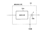
図1は、本発明に係る音声再生装置の実施の形態の構成例を示すブロック図である。図1において、1は入力端子、2は出力端子、3は遅延回路、4は基本波抽出回路、5は高調波発生回路、6はバンドパスフィルタ、7、8はアンプ、9は加算回路、10は高域成分抽出回路、11は高域レベル検出回路、12は低域レベル検出回路、13は制御量演算回路である。 FIG. 1 is a block diagram showing a configuration example of an embodiment of an audio reproduction device according to the present invention. In FIG. 1, 1 is an input terminal, 2 is an output terminal, 3 is a delay circuit, 4 is a fundamental wave extraction circuit, 5 is a harmonic generation circuit, 6 is a band pass filter, 7 and 8 are amplifiers, 9 is an adder circuit, 10 is a high frequency component extraction circuit, 11 is a high frequency level detection circuit, 12 is a low frequency level detection circuit, and 13 is a control amount calculation circuit.
次に動作を説明する。入力端子1からの音声信号が入力すると、遅延回路3と、基本波抽出回路4と、高域成分抽出回路7とに入力する。
Next, the operation will be described. When an audio signal from the input terminal 1 is input, it is input to the
遅延回路3は、入力音声信号を遅延し、主信号としてアンプ7へ出力する。
The
基本波抽出回路4は、入力音声信号から所望とするスピーカ(図示せず)の再生周波数帯域以下の周波数帯域である基本波帯域成分を抽出する。ここでは、基本波帯域成分として、スピーカ(図示せず)の最低共振周波数f_0付近のカットオフ周波数f_c未満の周波数帯域成分を抽出する。そして、抽出した基本波帯域成分を、高調波発生回路5と、低域レベル検出回路8とへ出力する。
The fundamental
図2は、図1の基本波抽出回路4の機能を説明する図である。基本波抽出回路4は、バンドパスフィルタ等で構成することができる。つまり、本装置から音声信号を出力するスピーカが、例えば、図2のようなスピーカ再生特性であった場合に、そのスピーカの最低共振周波数f_0付近に、カットオフ周波数f_cを選び、カットオフ周波数f_cの1/2である(f_c/2)と、カットオフ周波数f_cとの間を基本波帯域として通過させるバンドパスフィルタを用いる。これにより、スピーカで再生することが困難な低域の成分を抽出することができる。ここで、バンドパスフィルタの低域側のカットオフ周波数を(f_c/2)とするのは、(f_c/2)以下の成分を歪ませることによる高調波が(f_c/2)〜f_cの帯域に入ることを防ぐためである。
FIG. 2 is a diagram for explaining the function of the fundamental
ただし、簡易的にスピーカの最低共振周波数f0以下の周波数成分すべてを基本波帯域成分と考え、最低共振周波数f_0以下の周波数成分すべてを基本波帯域成分として通過させる図3のようにローパスフィルタを用いることも可能である。これは、低域における狭帯域のバンドパスフィルタを設計するのが困難な場合に有効である。 However, a low-pass filter is used as shown in FIG. 3 in which all frequency components below the lowest resonance frequency f0 of the speaker are simply considered as fundamental band components and all frequency components below the lowest resonance frequency f_0 are passed as fundamental band components. It is also possible. This is effective when it is difficult to design a narrow-band bandpass filter in the low frequency range.
高域成分抽出回路10は、スピーカ(図示せず)のカットオフ周波数f_c以上の周波数帯域、すなわち高調波帯域成分を抽出して、高域レベル検出回路11へ出力する。
The high frequency
一方、基本波抽出回路4の出力は低域レベル検出回路12にも送られており、低域レベル検出回路12は、抽出された基本波の所定短時間におけるレベルである低域レベルを計算する。
On the other hand, the output of the fundamental
同様に、高域成分抽出回路10の出力は高域レベル検出回路9に送られおり、カットオフ周波数f_c以上の高域周波数成分の所定短時間におけるレベルである高域レベルを計算する。
Similarly, the output of the high frequency
制御量演算回路13では、基本波抽出回路4からの低域のレベルと、高域成分抽出回路10からの高域のレベルとを比較し、高調波発生回路5における高調波の発生量を制御して、聴感上、入力音声信号に高調波歪が目立つ場合は、無理に高調波を付加しないように高調波の発生量を制御する。
In the control
高調波発生回路5では、制御量演算回路13からの高調波の発生量の制御信号に基づいて、基本波抽出回路4から得られた低音成分である基本波帯域成分を非線形処理して、低音成分の高調波を発生して、バンドパスフィルタ6へ出力する。高調波を発生させる非線形処理としては、既存の方法、例えば全波整流法、冪乗法などを利用することができる。なお、制御量演算回路13からの高調波の発生量の制御信号に基づく高調波発生回路5の高調波の発生処理については後述する。
The
バンドパスフィルタ6では、高調波発生回路5にて得られた高調波成分の内、不要な周波数成分を除去した後、アンプ8へ出力する。これは、所望とする高調波より高次の高調波、例えば約1kHz以上の成分は、バーチャルピッチ効果に寄与しないうえ、聴感的に敏感な帯域に悪影響を与えるからである。また、高調波発生回路5の処理では、高調波以外にも副次的に基本波帯域成分も発生する。このためこれらの高域成分や低域成分を除去することがバンドパスフィルタ6の目的である。
The band-pass filter 6 removes unnecessary frequency components from the harmonic components obtained by the
加算回路9は、アンプ7を介した遅延回路3によって遅延した主信号と、アンプ8を介したバンドパスフィルタ6からの出力信号とをユーザの設定や適当な比率をもって加算して出力端子2から出力する。
The adder circuit 9 adds the main signal delayed by the
低域レベル検出回路11は、基本波抽出回路4にて抽出された基本波帯域成分の信号レベルを検出する。検出方法は、数msecの間隔でデータを蓄積し、その区間における平均パワーを計算しても良い。また、処理を簡単に済ませる場合は該区間における最大値を検出して入力信号レベルの代替としても良い。
The low band
高域成分抽出回路10は、基本波帯域成分の帯域よりも高域の成分を抽出するハイパスフィルタ等で構成される。例えば、高域成分抽出回路10は、図5に示すように、基本波抽出回路4の高域側のカットオフ周波数f_c以上の周波数帯域を通過させるハイパスフィルタを使うことで実現できる。
The high-frequency
高域レベル検出回路11は、高域成分抽出回路10にて抽出された高域成分の信号レベルを検出して制御量演算回路13へ出力する。高域成分の信号レベルの検出方法は、低域レベル検出回路12と同様な方法が利用できる。ただし、データを蓄積する時間は低域レベル検出回路12よりも短くする必要がある。
The high frequency
制御量演算回路13は、高域レベル検出回路11にて検出された高域レベルに対する、低域レベル検出回路11にて検出された低域レベルの比率を計算し、計算した比率に応じて、例えば、図5に示すように高調波発生回路5における高調波発生の制御量を決定する。
The control
図5は、制御量演算回路13による高調波発生回路5における高調波発生制御の一例を示す図である。
FIG. 5 is a diagram illustrating an example of harmonic generation control in the
図5において、横軸は、高域レベル検出回路11にて検出された高域レベルに対する低域レベル検出回路11にて検出された低域レベルの比率(LHR)、すなわち(低域レベル/高域レベル)[dB]を示している。縦軸は高調波発生量を示しており、縦軸のmaxは、高調波発生量の最大値を示している。
In FIG. 5, the horizontal axis represents the ratio (LHR) of the low frequency level detected by the low frequency
そして、この例では、(低域レベル/高域レベル)[dB]の閾値として、2つの閾値R_th1、R_th2とを設けている。ここで、閾値R_th1としては、例えば、−4[dB]、閾値R_th2としては、例えば、+2[dB]である。ここで、2つの閾値R_th1、R_th2とを設けているのは、閾値R_th1以内であれば、高域成分が優勢で高調波を発生させて入力音声信号に加算しても聴感上歪として知覚されないので、高調波を最大限発生すように制御する一方、閾値R_th2を超えると、低域成分が優勢であるので高調波を発生させて入力音声信号に加算すると、その高調波が聴感上歪として知覚できるので、高調波の発生を0にするように制御する。 In this example, two threshold values R_th1 and R_th2 are provided as threshold values of (low frequency level / high frequency level) [dB]. Here, the threshold value R_th1 is, for example, −4 [dB], and the threshold value R_th2 is, for example, +2 [dB]. Here, the two threshold values R_th1 and R_th2 are provided as long as they are within the threshold value R_th1, and even if high frequency components are dominant and harmonics are generated and added to the input audio signal, they are not perceived as distortion in the sense of hearing. Therefore, while controlling to generate the maximum harmonics, if the threshold R_th2 is exceeded, the low-frequency component is dominant, so if harmonics are generated and added to the input audio signal, the harmonics will be distorted in terms of hearing. Since it can be perceived, the generation of harmonics is controlled to be zero.
つまり、制御量演算回路13は、(低域レベル/高域レベル)[dB]が閾値R_th1よりも小さいと判断した場合、高域成分が優勢であると判断して、高調波発生回路5における高調波発生量が最大MAXになるように制御する。
That is, if the control
これに対し、制御量演算回路13は、(低域レベル/高域レベル)[dB]が閾値R_th2よりも大きくなると判断した場合、低域成分が優勢であると判断して、制御量演算回路13は高調波の発生量を0、すなわち高調波を発生させないよう制御する。
In contrast, when the control
また、制御量演算回路13は、(低域レベル/高域レベル)[dB]が閾値R_th1と、閾値R_th2との中間である場合は、高調波発生量が(低域レベル/高域レベル)[dB]に応じた値になるように高調波発生回路5における高調波発生量を制御する。これは、高調波発生量が急激に変化すると、変化点において不連続点が発生するため、これを避けるのが目的である。
Further, when the (low frequency level / high frequency level) [dB] is intermediate between the threshold value R_th1 and the threshold value R_th2, the control
なお、高調波発生回路5の制御法は、高調波発生回路5の構成に依存する。
The method for controlling the
図6は、高調波発生回路5の構成の一例を示している。高調波発生回路5は、図6に示すように、高調波発生回路5の実体部分である非線形処理回路5aと、非線形処理回路5aの出力を調整するアンプ5b等により構成される。高調波発生回路5におけるアンプ5bの出力ゲインを制御することとすれば、高調波発生回路5の実体部分である非線形処理回路5aに依存しない簡便な制御法となる。
FIG. 6 shows an example of the configuration of the
また、図6に示すように高調波発生回路5におけるアンプ5bの出力ゲインを制御するのではなく、高調波発生回路5の実体部分である非線形処理回路5aの非線形処理自体を(低域レベル/高域レベル)[dB]に応じて制御するようにしても勿論よい。
In addition, as shown in FIG. 6, the output gain of the amplifier 5b in the
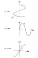
図7は、高調波発生回路5の実体部分である非線形処理回路5aにおける非線形処理の制御の一例を示している。
FIG. 7 shows an example of non-linear processing control in the non-linear processing circuit 5 a which is the substantial part of the
つまり、図7(c)は、非線形処理の入出力特性を示していて、非線形処理回路5aの非線形処理のパラメータを制御することによって、その特性を自由に変更できるものとする。ここで、特性αは入力が小さいときほど出力が大きくなるような非線形特性、特性Lは線形特性であり、非線形処理回路5aの非線形処理のパラメータを制御することによってこれらの特性α,Lを設定することができる。 That is, FIG. 7C shows the input / output characteristics of the nonlinear processing, and the characteristics can be freely changed by controlling the parameters of the nonlinear processing of the nonlinear processing circuit 5a. Here, the characteristic α is a non-linear characteristic such that the output becomes larger as the input is smaller, and the characteristic L is a linear characteristic, and these characteristics α and L are set by controlling the parameters of the non-linear processing of the non-linear processing circuit 5a. can do.
すると、図7(a)のように正弦波の入力信号が入力すると、特性αの入出力特性を用いれば、図7図(b)の実線、特性Lの入出力特性を用いれば破線のような出力信号が得られる。 Then, when a sine wave input signal is input as shown in FIG. 7 (a), if the input / output characteristic of the characteristic α is used, the solid line in FIG. An output signal can be obtained.
そのため、高調波発生回路5におけるアンプ5bの出力ゲインを制御する場合と同様に、(低域レベル/高域レベル)[dB]に応じて図7(c)の特性α,Lに適宜変更されるように、非線形処理回路5aの非線形処理のパラメータを制御すれば、出力波形の歪み量を制御できる。
Therefore, as in the case of controlling the output gain of the amplifier 5b in the
従って、本実施の形態によれば、高域レベルに対する低域レベルの比率と、入力音声信号に加算する高調波が歪みとなるか否かの前記比率の閾値とに基づいて、入力音声信号に加算する高調波が歪みとならないように高調波の発生量を制御するので、高調波成分を原音である入力音声信号に付加する場合でも、歪みの少ない音を得ることができる。 Therefore, according to the present embodiment, based on the ratio of the low frequency level to the high frequency level and the threshold value of the ratio indicating whether or not the harmonic added to the input audio signal is distorted, the input audio signal is Since the amount of harmonics generated is controlled so that the harmonics to be added are not distorted, a sound with little distortion can be obtained even when a harmonic component is added to the input audio signal that is the original sound.
特に、本実施の形態では、高域レベルに対する低域レベルの比率と、高調波が歪みとなるか否かの前記比率の下限閾値R_th1と上限閾値R_th2とに基づいて、入力音声信号に加算する高調波が歪みとならないよう、前記比率が下限閾値R_th1より小さい場合は、入力音声信号に加算する高調波の発生量を最大に制御する一方、前記比率が上限閾値R_th2より大きい場合は、入力音声信号に加算する高調波の発生量をゼロにするようにしたので、さらに歪みの少ない音を得ることができる。 In particular, in the present embodiment, the low frequency level is added to the input audio signal based on the ratio of the low frequency level to the high frequency level and the lower limit threshold value R_th1 and the upper limit threshold value R_th2 of the ratio indicating whether the harmonics are distorted or not. To prevent harmonics from becoming distorted, when the ratio is smaller than the lower threshold R_th1, the amount of harmonics added to the input voice signal is controlled to the maximum, while when the ratio is larger than the upper threshold R_th2, the input voice Since the amount of harmonics added to the signal is set to zero, a sound with even less distortion can be obtained.
また、本実施の形態では、高域レベルに対する低域レベルの比率と、高調波が歪みとなるか否かの前記比率の下限閾値R_th1と上限閾値R_th2とに基づいて、前記比率が下限閾値R_th1と上限閾値R_th2との間の場合、入力音声信号に加算する高調波が歪みとならないように、高調波の発生量を前記比率に応じ制御するようにしたので、入力音声信号に加算する高調波発生量を滑らかに制御して、より歪みの少ない音を得ることができる。 Further, in the present embodiment, based on the ratio of the low frequency level to the high frequency level and the lower limit threshold R_th1 and the upper limit threshold R_th2 of the ratio as to whether or not the harmonics are distorted, the ratio is the lower limit threshold R_th1. And the upper threshold R_th2, the harmonics added to the input audio signal are controlled according to the ratio so that the harmonics added to the input audio signal will not be distorted. A sound with less distortion can be obtained by smoothly controlling the amount of generation.
4 基本波抽出回路(基本波抽出手段)
5 高調波発生回路(高調波発生手段)
10 高域成分抽出回路(高域成分抽出手段)
11 高域レベル検出回路(高域レベル検出手段)
12 低域レベル検出回路(低域レベル検出手段)
13 制御量演算回路(制御手段)
4 fundamental wave extraction circuit (fundamental wave extraction means)
5 Harmonic generation circuit (harmonic generation means)
10 High-frequency component extraction circuit (High-frequency component extraction means)
11 High frequency level detection circuit (High frequency level detection means)
12 Low frequency level detection circuit (Low frequency level detection means)
13 Control amount calculation circuit (control means)
Claims (3)
前記入力音声信号から前記スピーカの再生周波数帯域以下の周波数帯域である基本波帯域成分を抽出する基本波抽出手段と、
前記基本波帯域成分の高調波を発生する高調波発生手段と、
前記基本波帯域成分のレベルを低域レベルとして検出する低域レベル検出手段と、
前記入力音声信号から前記基本波帯域成分より上の高調波帯域成分を抽出する高域成分抽出手段と、
前記高調波帯域成分のレベルを高域レベルとして検出する高域レベル検出手段と、
前記高域レベルに対する前記低域レベルの比率と、前記高調波発生手段が発生した前記高調波が歪みとなるか否かの前記比率の閾値とに基づいて、前記高調波が歪みとならないように前記高調波発生手段における前記高調波の発生量を制御する制御手段と、
を有する音声再生装置。 An audio reproduction device that adds harmonics based on the input audio signal to an input audio signal and outputs the resultant to a speaker,
Fundamental wave extraction means for extracting a fundamental wave band component that is a frequency band below the reproduction frequency band of the speaker from the input audio signal;
Harmonic generation means for generating harmonics of the fundamental band component;
Low frequency level detection means for detecting the level of the fundamental wave band component as a low frequency level;
High-frequency component extracting means for extracting higher harmonic band components above the fundamental wave band components from the input audio signal;
High frequency level detection means for detecting the level of the harmonic band component as a high frequency level;
Based on the ratio of the low frequency level to the high frequency level and the threshold value of the ratio indicating whether the harmonic generated by the harmonic generation means is distorted or not, the harmonics are not distorted. Control means for controlling the amount of generation of the harmonics in the harmonic generation means;
An audio reproducing apparatus having
前記制御手段は、
前記高域レベルに対する前記低域レベルの比率と、前記高調波発生手段が発生した前記高調波が歪みとなるか否かの前記比率の下限閾値と上限閾値とに基づいて、前記高調波が歪みとならないよう、前記比率が前記下限閾値より小さい場合は、前記高調波発生手段における前記高調波の発生量を最大に制御する一方、前記比率が前記上限閾値より大きい場合は、前記高調波発生手段における前記高調波の発生量をゼロに制御する、音声再生装置。 In the audio playback device according to claim 1,
The control means includes
The harmonics are distorted based on a ratio of the low level to the high level and a lower limit threshold and an upper limit threshold of the ratio as to whether or not the harmonic generated by the harmonic generation unit is distorted. When the ratio is smaller than the lower limit threshold, the harmonic generation amount in the harmonic generation means is controlled to the maximum, while when the ratio is larger than the upper limit threshold, the harmonic generation means A sound reproducing device for controlling the generation amount of the harmonics in to zero.
前記制御手段は、
前記高域レベルに対する前記低域レベルの比率と、前記高調波発生手段が発生した前記高調波が歪みとなるか否かの前記比率の下限閾値と上限閾値とに基づいて、前記比率が前記下限閾値と前記上限閾値との間の場合、前記高調波が歪みとならないよう、前記高調波発生手段における前記高調波の発生量を前記比率に応じ制御する、音声再生装置。 The sound reproducing device according to claim 1 or 2,
The control means includes
Based on the ratio of the low frequency level to the high frequency level and the lower and upper thresholds of the ratio as to whether the harmonic generated by the harmonic generation means is distorted, the ratio is the lower limit. An audio reproduction device that controls the amount of harmonics generated by the harmonic generation means according to the ratio so that the harmonics do not become distorted between the threshold and the upper threshold.
Priority Applications (1)
| Application Number | Priority Date | Filing Date | Title |
|---|---|---|---|
| JP2008091932A JP4983694B2 (en) | 2008-03-31 | 2008-03-31 | Audio playback device |
Applications Claiming Priority (1)
| Application Number | Priority Date | Filing Date | Title |
|---|---|---|---|
| JP2008091932A JP4983694B2 (en) | 2008-03-31 | 2008-03-31 | Audio playback device |
Publications (2)
| Publication Number | Publication Date |
|---|---|
| JP2009244650A JP2009244650A (en) | 2009-10-22 |
| JP4983694B2 true JP4983694B2 (en) | 2012-07-25 |
Family
ID=41306592
Family Applications (1)
| Application Number | Title | Priority Date | Filing Date |
|---|---|---|---|
| JP2008091932A Active JP4983694B2 (en) | 2008-03-31 | 2008-03-31 | Audio playback device |
Country Status (1)
| Country | Link |
|---|---|
| JP (1) | JP4983694B2 (en) |
Families Citing this family (8)
| Publication number | Priority date | Publication date | Assignee | Title |
|---|---|---|---|---|
| US8971551B2 (en) | 2009-09-18 | 2015-03-03 | Dolby International Ab | Virtual bass synthesis using harmonic transposition |
| WO2014060204A1 (en) * | 2012-10-15 | 2014-04-24 | Dolby International Ab | System and method for reducing latency in transposer-based virtual bass systems |
| EP2362375A1 (en) * | 2010-02-26 | 2011-08-31 | Fraunhofer-Gesellschaft zur Förderung der Angewandten Forschung e.V. | Apparatus and method for modifying an audio signal using harmonic locking |
| JP5598536B2 (en) * | 2010-03-31 | 2014-10-01 | 富士通株式会社 | Bandwidth expansion device and bandwidth expansion method |
| CN104012001B (en) * | 2011-12-27 | 2017-10-27 | Dts有限责任公司 | Bass boost system |
| CN108989950B (en) * | 2012-05-29 | 2023-07-25 | 创新科技有限公司 | Adaptive bass processing system |
| WO2020222242A1 (en) * | 2019-04-30 | 2020-11-05 | Waves Audio Ltd. | Dynamic reduction of loudspeaker distortion based on psychoacoustic masking |
| JP7475988B2 (en) * | 2020-06-26 | 2024-04-30 | ローランド株式会社 | Effects device and effects processing program |
Family Cites Families (3)
| Publication number | Priority date | Publication date | Assignee | Title |
|---|---|---|---|---|
| US5930373A (en) * | 1997-04-04 | 1999-07-27 | K.S. Waves Ltd. | Method and system for enhancing quality of sound signal |
| JP3810257B2 (en) * | 2000-06-30 | 2006-08-16 | 松下電器産業株式会社 | Voice band extending apparatus and voice band extending method |
| JP2005269543A (en) * | 2004-03-22 | 2005-09-29 | Sanyo Electric Co Ltd | Bass enhancing circuit |
-
2008
- 2008-03-31 JP JP2008091932A patent/JP4983694B2/en active Active
Also Published As
| Publication number | Publication date |
|---|---|
| JP2009244650A (en) | 2009-10-22 |
Similar Documents
| Publication | Publication Date | Title |
|---|---|---|
| JP4983694B2 (en) | Audio playback device | |
| JP5917518B2 (en) | Speech signal dynamic correction for perceptual spectral imbalance improvement | |
| JP4666229B2 (en) | Audio playback device | |
| JP4869352B2 (en) | Apparatus and method for processing an audio data stream | |
| JP2005318598A (en) | Improvement on or concerning signal processing | |
| EP2928076B1 (en) | Level adjustment device and method | |
| JP2010244602A (en) | Signal processing device, method, and program | |
| US10128809B2 (en) | Intelligent method and apparatus for spectral expansion of an input signal | |
| KR101329308B1 (en) | Method for enhancing Bass of Audio signal and apparatus therefore, Method for calculating fundamental frequency of audio signal and apparatus therefor | |
| JP5340121B2 (en) | Audio signal playback device | |
| JP5046786B2 (en) | Pseudo deep bass generator | |
| JP4787316B2 (en) | Digital signal processing apparatus and overtone generation method | |
| JP2006324786A (en) | Acoustic signal processing apparatus and method | |
| JP6155132B2 (en) | Low frequency complement device and low frequency complement method | |
| JP5958378B2 (en) | Audio signal processing apparatus, control method and program for audio signal processing apparatus | |
| JP5145733B2 (en) | Audio signal processing apparatus, audio signal processing method, and program | |
| JP5268581B2 (en) | Low frequency complementer | |
| JP4803193B2 (en) | Audio signal gain control apparatus and gain control method | |
| JP2008227681A (en) | Acoustic characteristic correction system | |
| JP2012129839A (en) | Acoustic signal processing apparatus and method, and program | |
| JP6603725B2 (en) | Audio signal generation apparatus, audio signal generation method, and program | |
| JP6314803B2 (en) | Signal processing apparatus, signal processing method, and program | |
| JP6226166B2 (en) | Sound playback device | |
| JP6313629B2 (en) | Audio signal processing apparatus, control method and program for audio signal processing apparatus | |
| US9653065B2 (en) | Audio processing device, method, and program |
Legal Events
| Date | Code | Title | Description |
|---|---|---|---|
| A621 | Written request for application examination |
Free format text: JAPANESE INTERMEDIATE CODE: A621 Effective date: 20101203 |
|
| A711 | Notification of change in applicant |
Free format text: JAPANESE INTERMEDIATE CODE: A712 Effective date: 20111012 |
|
| A977 | Report on retrieval |
Free format text: JAPANESE INTERMEDIATE CODE: A971007 Effective date: 20120319 |
|
| TRDD | Decision of grant or rejection written | ||
| A01 | Written decision to grant a patent or to grant a registration (utility model) |
Free format text: JAPANESE INTERMEDIATE CODE: A01 Effective date: 20120327 |
|
| A01 | Written decision to grant a patent or to grant a registration (utility model) |
Free format text: JAPANESE INTERMEDIATE CODE: A01 |
|
| A61 | First payment of annual fees (during grant procedure) |
Free format text: JAPANESE INTERMEDIATE CODE: A61 Effective date: 20120409 |
|
| R150 | Certificate of patent or registration of utility model |
Free format text: JAPANESE INTERMEDIATE CODE: R150 Ref document number: 4983694 Country of ref document: JP Free format text: JAPANESE INTERMEDIATE CODE: R150 |
|
| FPAY | Renewal fee payment (event date is renewal date of database) |
Free format text: PAYMENT UNTIL: 20150511 Year of fee payment: 3 |