JP2005318598A - Improvement on or concerning signal processing - Google Patents
Improvement on or concerning signal processing Download PDFInfo
- Publication number
- JP2005318598A JP2005318598A JP2005128302A JP2005128302A JP2005318598A JP 2005318598 A JP2005318598 A JP 2005318598A JP 2005128302 A JP2005128302 A JP 2005128302A JP 2005128302 A JP2005128302 A JP 2005128302A JP 2005318598 A JP2005318598 A JP 2005318598A
- Authority
- JP
- Japan
- Prior art keywords
- signal
- low
- low frequency
- frequency
- peak hold
- Prior art date
- Legal status (The legal status is an assumption and is not a legal conclusion. Google has not performed a legal analysis and makes no representation as to the accuracy of the status listed.)
- Pending
Links
Images


Classifications
-
- H—ELECTRICITY
- H04—ELECTRIC COMMUNICATION TECHNIQUE
- H04S—STEREOPHONIC SYSTEMS
- H04S1/00—Two-channel systems
- H04S1/002—Non-adaptive circuits, e.g. manually adjustable or static, for enhancing the sound image or the spatial distribution
-
- H—ELECTRICITY
- H04—ELECTRIC COMMUNICATION TECHNIQUE
- H04S—STEREOPHONIC SYSTEMS
- H04S5/00—Pseudo-stereo systems, e.g. in which additional channel signals are derived from monophonic signals by means of phase shifting, time delay or reverberation
Landscapes
- Physics & Mathematics (AREA)
- Engineering & Computer Science (AREA)
- Acoustics & Sound (AREA)
- Signal Processing (AREA)
- Circuit For Audible Band Transducer (AREA)
- Stereophonic System (AREA)
Abstract
Description
本発明は、オーディオ信号処理の方法および装置に関し、特に低域周波数の音響心理学的な知覚を介してより明瞭な低音を伝えるのに適用される。 The present invention relates to a method and apparatus for audio signal processing, and is particularly adapted to convey clearer bass through low-frequency psychoacoustic perception.
スピーカなどの音響変換器では、一般的に低音(すなわち、低域周波数)周波数帯域を再生するのが困難である。 In an acoustic transducer such as a speaker, it is generally difficult to reproduce a bass (that is, a low frequency) frequency band.
明瞭な低音周波数帯域を発生させるために、倍音を利用することが知られている。このことは、基本音が存在しない場合であっても、低周波音の倍音があると聴取者には低い基本周波数が「聴こえる」という音響心理学的な現象からもたらされる。 In order to generate a clear bass frequency band, it is known to use overtones. This comes from the psychoacoustic phenomenon that even if there is no fundamental sound, the listener can “listen” to a low fundamental frequency when there is a harmonic of a low frequency sound.
公知の装置または方法では、コンプレッサやリミッタなどの装置を用いてダイナミックレンジ(すなわち、音量または信号レベル)全域にわたって信号を変化させる。 Known devices or methods use a device such as a compressor or limiter to change the signal over the entire dynamic range (ie volume or signal level).
本発明の目的は、少なくとも既存の方法および装置にとって代わる有用な方法および装置となりうる改良されたオーディオ信号処理方法またはオーディオ信号処理装置を提供することにある。 It is an object of the present invention to provide an improved audio signal processing method or audio signal processing apparatus that can be a useful method and apparatus replacing at least the existing method and apparatus.
本発明のさらなる目的は、以下の説明から明らかになり得る。 Further objects of the present invention can become clear from the following description.
本発明は、一局面によれば、低周波オーディオ信号を音響心理学的に聴取者に知覚させるのに適したオーディオ信号を生成する信号処理装置に関するものであり、この装置は、低周波信号の波形を時間について整形することにより低周波信号の倍音を生成するピークホールド信号発生手段を含む。 According to one aspect, the present invention relates to a signal processing apparatus that generates an audio signal suitable for causing a listener to perceive a low-frequency audio signal psychoacoustically. Peak hold signal generating means for generating harmonics of the low frequency signal by shaping the waveform with respect to time is included.
好ましくは、上記ピークホールド信号発生器は、低周波信号の波形をレベルについて整形する信号減衰手段を含む。 Preferably, the peak hold signal generator includes signal attenuation means for shaping the waveform of the low frequency signal with respect to the level.
好ましくは、上記倍音生成手段は、奇数および偶数倍音を生成する。 Preferably, the harmonic overtone generating means generates odd and even overtones.
好ましくは、上記装置は、偶数倍音を生成する整流器を含む。 Preferably, the device includes a rectifier that generates even harmonics.
好ましくは、上記ピークホールド信号発生器は、ピークホールド減衰信号発生器を備える。 Preferably, the peak hold signal generator comprises a peak hold attenuation signal generator.
好ましくは、上記低周波信号の波形は、時間およびレベルについて非対称に整形される。 Preferably, the waveform of the low frequency signal is shaped asymmetrically with respect to time and level.
別の局面では、本発明は、低周波オーディオ信号を音響心理学的に聴取者に知覚させるのに適したオーディオ出力信号を生成するために低周波オーディオ信号を処理する方法に関するものであり、この方法は、実質的にピークマグニチュードまで低周波信号に追随し、零交叉に達した後は再び逆の極性において前記信号に追随することによって、低周波信号の波形を時間について整形するステップを含む。 In another aspect, the invention relates to a method of processing a low frequency audio signal to produce an audio output signal suitable for psychoacoustically perceiving the low frequency audio signal. The method includes shaping the waveform of the low frequency signal with respect to time by following the low frequency signal substantially to peak magnitude, and following the signal again in the opposite polarity after reaching zero crossing.
好ましくは、上記方法は、実質的にピークマグニチュードまで前記低周波信号に追随し、その後前記ピークマグニチュードを所定のレートで減衰させることによって、前記低周波信号の波形を時間およびレベルについて整形するステップを含む。 Preferably, the method comprises following the low frequency signal substantially to peak magnitude and then shaping the waveform of the low frequency signal with respect to time and level by attenuating the peak magnitude at a predetermined rate. Including.
本発明はまた、広義には、本明細書で開示する新規な任意の特徴部分からなるか、または複数の特徴部分を組合せたものと言うことができる。 The invention can also be broadly defined as any novel feature disclosed herein or a combination of features.
本発明のさらなる新規な態様は、以下の説明から明らかとされる。 Further novel aspects of the present invention will become apparent from the following description.
以下に、添付図面を参照して本発明の実施形態を例を挙げて説明する。
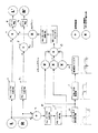
図1は、本発明の信号処理回路の第1の実施形態の概略ブロック図である。
図2は、本発明の信号処理回路の第2の実施形態の概略ブロック図である。
図3は、本発明の信号処理回路の第3の実施形態の概略ブロック図である。
図4は、本発明の信号処理回路の第4の実施形態の概略ブロック図である。
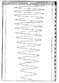
図5は、図4の実施形態において使用されるピークホールド減衰生成器によって生成された倍音波形の例を示すグラフである。測定音の44.1kHzのサンプリング・レートで示される時間を横軸に、信号レベルを縦軸に示す。
図6は、倍音成分の第1の例の周波数(Hz)−信号強度(dB)のグラフである。
図7は、倍音成分の第2の例の周波数(Hz)−信号強度(dB)のグラフである。
図8は、倍音成分の第3の例の周波数(Hz)−信号強度(dB)のグラフである。
Embodiments of the present invention will be described below by way of example with reference to the accompanying drawings.
FIG. 1 is a schematic block diagram of a first embodiment of a signal processing circuit of the present invention.
FIG. 2 is a schematic block diagram of a second embodiment of the signal processing circuit of the present invention.
FIG. 3 is a schematic block diagram of a third embodiment of the signal processing circuit of the present invention.
FIG. 4 is a schematic block diagram of a fourth embodiment of the signal processing circuit of the present invention.
FIG. 5 is a graph illustrating an example of a harmonic shape generated by a peak hold attenuation generator used in the embodiment of FIG. The time indicated by the 44.1 kHz sampling rate of the measurement sound is shown on the horizontal axis, and the signal level is shown on the vertical axis.
FIG. 6 is a graph of frequency (Hz) -signal intensity (dB) of the first example of overtone components.
FIG. 7 is a graph of frequency (Hz) -signal intensity (dB) of the second example of the overtone component.
FIG. 8 is a graph of frequency (Hz) -signal intensity (dB) of the third example of the harmonic component.
図1に、信号処理システムの第1の実施形態のブロック図を示す。 FIG. 1 shows a block diagram of a first embodiment of a signal processing system.
図1に示す回路は、ソフトウェアにて実施してもよく、、物理的ハードウェアを用いて実施してもよい。さらに、この回路は、デジタル形式またはアナログ形式で構成することもできる。どちらの形式でも、所望の結果が得られる多数の理論および技術がある。 The circuit shown in FIG. 1 may be implemented by software or may be implemented using physical hardware. Furthermore, the circuit can be configured in digital or analog form. In either form, there are a number of theories and techniques that can achieve the desired results.
このシステムの目的は、任意のオーディオ出力機構によって任意のオーディオソースから聴取者により明瞭な低音を伝えることにある。 The purpose of this system is to convey a clear bass to the listener from any audio source by any audio output mechanism.
チャンネルごとに(L、Rなど。本発明は単一チャンネルまたは複数チャンネルのオーディオ・システムに適用可能である。)オーディオソース入力信号をハイパスフィルタ(1、2)にかけて低音成分を除去し、後に使用するため、チャンネルごとにろ波された入力信号を生成することが望ましい(ろ波後の入力信号)。次に、これらのチャンネルのオーディオソース入力信号を加算して(3)、原音中に低音周波数成分の全量を含んだ単一ソース信号を生成することが好ましい。その後、得られた信号をハイパスフィルタ(4)およびローパスフィルタ(5)にかけて、極超低音周波数帯域および非低音周波数帯域を除去し、低音ソース信号を生成する。 For each channel (L, R, etc. The present invention is applicable to single channel or multi-channel audio systems.) The audio source input signal is passed through a high-pass filter (1, 2) to remove bass components for later use. Therefore, it is desirable to generate an input signal filtered for each channel (input signal after filtering). Next, it is preferable to add the audio source input signals of these channels (3) to generate a single source signal that includes the entire amount of bass frequency components in the original sound. Thereafter, the obtained signal is passed through a high-pass filter (4) and a low-pass filter (5) to remove the extremely low frequency band and the non-low frequency band, thereby generating a low frequency source signal.
通常(6)で示される倍音生成部を用いて、倍音を上記の低音ソース信号に付加する。このプロセスによって、低音出力信号が生成され、次いでこの信号がろ波後の入力信号と合成される。このプロセスの詳細については後述する。 A harmonic is added to the above-mentioned bass source signal using a harmonic generation unit normally indicated by (6). This process produces a bass output signal that is then combined with the filtered input signal. Details of this process will be described later.
最終的に出力される音響は、ろ波後の入力信号(7、8)の各々に低音出力信号を加算し、その結果をオーディオ出力信号(スピーカ、ヘッドフォン等)に与えることで生成される。ピーキング・イコライザ(一般にステレオ・システムに搭載されている標準的な「低音ブースト」に類似のもの)(9)を適宜付加するかまたはその後に別途設け、さらにオーディオ出力信号に低音出力レベル調整を行い、それによってすでに付加された倍音成分を全量含んだ状態であってもさらに低周波数応答を向上させることができる。 The sound that is finally output is generated by adding a bass output signal to each of the filtered input signals (7, 8) and giving the result to an audio output signal (speaker, headphones, etc.). Add a peaking equalizer (similar to the standard “bass boost” commonly found in stereo systems) (9) as appropriate, or provide it separately, and adjust the bass output level to the audio output signal. As a result, the low frequency response can be further improved even in a state where all the added harmonic components are included.
倍音生成部(6)は、次のように機能させることが好ましい。低音ソース信号をピークホールド信号発生器(10)に与える。ピークホールド信号発生器は、入力信号に追従して、その増加(または減少)に伴い、連続的に増加(または減少)し、入力信号が正負いずれの範囲でもその最大の値に保持される出力信号を生成する。入力信号が正から負または負から正の信号レベルに遷移するとき、ピークホールド信号発生器の出力は0(ゼロ)に設定される。この発生器は、オーディオ信号を時間について対称的に整形することにより、基本周波数の奇数倍音を生成する。人間の耳が「位相音痴(phase deaf)」である、すなわちオーディオ信号の位相が聴取者には判別できないので、このプロセスは容易に機能しうる。このようにオーディオ信号を整形することにより、倍音生成器は、特定の一連の倍音を付加することで、倍音出力の位相に関係なく、所望の音響心理学的な低周波数応答が得られる。 The harmonic overtone generator (6) preferably functions as follows. Apply the bass source signal to the peak hold signal generator (10). The peak hold signal generator follows the input signal and continuously increases (or decreases) as the input signal increases (or decreases). Generate a signal. When the input signal transitions from positive to negative or from negative to positive signal level, the output of the peak hold signal generator is set to 0 (zero). This generator generates odd harmonics of the fundamental frequency by shaping the audio signal symmetrically with respect to time. This process can easily work because the human ear is "phase deaf", i.e. the phase of the audio signal cannot be discerned by the listener. By shaping the audio signal in this way, the harmonic generator can add a specific series of harmonics to obtain the desired psychoacoustic low frequency response regardless of the phase of the harmonic output.
上記低音入力には、ヒステリシス関数を適用することが好ましく、これにより、入力信号レベルが所定のスレショルド値より低い場合、ピークホールド信号発生器から出力させないようにする。これは、信号遷移範囲を0(ゼロ)のみから±信号の範囲に拡張することによって実現される。 A hysteresis function is preferably applied to the bass input so that when the input signal level is lower than a predetermined threshold value, it is not output from the peak hold signal generator. This is achieved by extending the signal transition range from 0 (zero) only to the ± signal range.
その後、ピークホールド信号発生器出力(ピークホールド出力信号)を半波整流し(11)(これにより、原信号の正部分のみが保持される。)、偶数倍音を生成することが好ましい。それに続いて、直流阻止フィルタ(12)を通過させ、上記出力信号の直流バイアスを除去する。これが整流器出力信号である。 Thereafter, the peak hold signal generator output (peak hold output signal) is preferably half-wave rectified (11) (only the positive part of the original signal is thereby held) to generate even overtones. Subsequently, a DC blocking filter (12) is passed to remove the DC bias of the output signal. This is the rectifier output signal.
次いで、算術加算器13において(加算および/または減算を適宜組合せることによって)、ピークホールド出力信号、低音ソース信号、および整流器出力信号を最終出力レベルゲインと加算して、倍音成分を多く含む低音信号を生成する。次いで、この倍音を含む低音信号をハイパスおよびローパスフィルタにかけて、望ましくないか、またはオーディオ出力手法によって再生できない倍音成分を除去し、低減する。 Then, in the arithmetic adder 13 (by appropriately combining addition and / or subtraction), the peak hold output signal, the bass source signal, and the rectifier output signal are added to the final output level gain to obtain a bass that contains a lot of harmonic components. Generate a signal. The bass signal containing the harmonics is then subjected to a high pass and low pass filter to remove and reduce harmonic components that are undesirable or cannot be reproduced by the audio output technique.
このアルゴリズムは、デジタル形式でもアナログ形式でも容易に実現することができる。デジタル形式では、アルゴリズムは、所定のフィルタとして例えばオーディオ双2次フィルタを用い、および倍音生成器のピークホールド信号および整流信号を生成させる基本的な数学的関数を利用することによって実現できる。 This algorithm can be easily implemented in either digital or analog form. In digital form, the algorithm can be implemented by using, for example, an audio biquadratic filter as the predetermined filter and utilizing basic mathematical functions that generate the harmonic hold peak hold and rectified signals.
アナログ形式では、ピークホールド信号発生器は、調整可能なピーク検出回路もしくはコンデンサ充電回路により、または出力信号を発生させるその他の手段により実現され、零交叉(信号遷移によりスレショルド値に達する)まで上記ソース入力低音信号のピーク値に保持できる。半波整流および直流阻止フィルタは、単純な整流ダイオードからオペアンプまでの様々な方法で実現することができる。 In analog form, the peak hold signal generator is realized by an adjustable peak detection circuit or capacitor charging circuit, or by other means for generating an output signal, and the above sources up to zero crossing (threshold value is reached by signal transition) It can be held at the peak value of the input bass signal. Half-wave rectification and DC blocking filters can be realized in a variety of ways, from simple rectifier diodes to operational amplifiers.
ピークホールド信号発生器によって行われる波形整形は、次のように記述することができる。
a)入力の増減中は入力信号に追随する。
b)+ve値および−ve値では、そのレベルで信号を保持する。
c)零交叉時に保持された値をゼロにリセットする。
The waveform shaping performed by the peak hold signal generator can be described as follows.
a) Follows the input signal while the input is increasing or decreasing.
b) For + ve and -ve values, hold the signal at that level.
c) Reset the value held at zero crossing to zero.
ヒステリシス関数を入力レベルに適用して、入力信号が特定の信号レベル(−30dBと規定)を超えたときのみ、出力を制限することが好ましい。このことは、「ゼロにリセットする」入力の範囲をゼロ入力に対して±30dBレベルの範囲に拡張することによって実現できる。これによって、過渡的な交差をなくすとともに、さらにより高い周波数の低音成分を不必要に生成することなく、存在する最も低い低音周波数を確実に検出しかつ生成する。 It is preferred to apply a hysteresis function to the input level to limit the output only when the input signal exceeds a certain signal level (defined as -30 dB). This can be achieved by extending the range of the “reset to zero” input to a range of ± 30 dB level relative to the zero input. This ensures that the lowest bass frequency present is detected and generated without the need for transient crossings and without unnecessarily generating even higher frequency bass components.
ヒステリシスを備えたピークホールドプロセスは、以下のように簡潔に記述することができる。
S(t)−時間(t)でのソース信号
O(t)−時間(t)での出力信号
レベル−ヒステリシス・レベル(±最小レベル/必要な音量)
とすると、
(S(t)≧−レベル)かつ(S(t)≦+レベル)の場合、
O(t)=0.0
上記条件を満たさず、(S(t)>O(t−1))かつ(S(t)>0.0)の場合、
O(t)=S(t)
上記2つの条件を満たさず、(S(t)<O(t−1))かつ(S(t)<0.0)の場合、
O(t)=S(t)
上記いずれの条件をも満たさない場合、
O(t)=O(t−1)
終わり
The peak hold process with hysteresis can be described briefly as follows.
S (t)-Source signal at time (t) O (t)-Output signal at time (t) Level-Hysteresis level (± minimum level / required volume)
Then,
In the case of (S (t) ≧ −level) and (S (t) ≦ + level),
O (t) = 0.0
If the above condition is not satisfied and (S (t)> O (t−1)) and (S (t)> 0.0),
O (t) = S (t)
When the above two conditions are not satisfied and (S (t) <O (t−1)) and (S (t) <0.0),
O (t) = S (t)
If none of the above conditions are met,
O (t) = O (t-1)
the end
処理経路において、+3dBのスケーリングゲインを加えて、種々の倍音と合成された信号レベルとのバランスを適切にとった。最終出力ゲインを補償するために相応して大きくすることで、初期ソース信号の3dB低下を同様に使用できた。このゲイン調整は、開発中に各信号のゲインが個別に調整可能となったソフトウェア・インターフェースによるものである。このゲインを加えた結果、倍音および低音の加算部への各入力について、ゲインファクタを公称、「0dB」とすることができた。 In the processing path, a scaling gain of +3 dB was added to properly balance the various harmonics with the synthesized signal level. By correspondingly increasing the final output gain to compensate, a 3 dB reduction in the initial source signal could be used as well. This gain adjustment is based on a software interface in which the gain of each signal can be individually adjusted during development. As a result of adding this gain, the gain factor was nominally “0 dB” for each input to the overtone and bass adders.
図1に掲げた周波数カットオフ値は、100Hz対応のスピーカ用にソフトウェアを実行させる際に、(入力に対して)0dBの総合ゲインが得られるように特に選択されたものである。ソフトウェアによる好ましい実施態様では、適切にカスケード接続されたデジタルオーディオ双2次フィルタ(2次)を用いて、所望のフィルタ次数を生成する。より低周波数帯域を扱うヘッドフォンまたはスピーカでは、異なるフィルタ・カットオフ設定値を用いる必要がありうる。簡単な1回の調整で出力周波数のカットオフ限界を変えることによって基本周波数をより多く出力に付加することができ、その結果、さらに豊かな低音が得られる。ただし、これにより、出力信号にそれに応じた電力が付加されることになる。 The frequency cut-off values listed in FIG. 1 are specifically selected so that an overall gain of 0 dB is obtained (relative to the input) when executing software for a 100 Hz speaker. In a preferred implementation by software, a suitably cascaded digital audio biquad filter (second order) is used to generate the desired filter order. Headphones or speakers that handle lower frequency bands may need to use different filter cutoff settings. More fundamental frequencies can be added to the output by changing the output frequency cut-off limit with a simple adjustment, resulting in a richer bass. However, as a result, power corresponding to the output signal is added.
ソフトウェアを実行することで−15dB、20Hzから1kHzの間で正弦波スイープ試験を行い、適切に付加された倍音を有する比較的平坦な−15dBの出力信号を生成するようにフィルタ・カットオフを調整することで、0dBゲイン経路であることが検証された。出力は、70Hz〜100Hzの周波数帯域に対して1.5dBの適度なゲインを有し、また180Hzの入力フィルタ・カットオフ周波数付近で1.5dB低下することが分かった。 Run the software to perform a sine wave sweep test between -15 dB and 20 Hz to 1 kHz, and adjust the filter cutoff to produce a relatively flat -15 dB output signal with appropriately added harmonics By doing so, it was verified that it is a 0 dB gain path. It has been found that the output has a moderate gain of 1.5 dB for the frequency band of 70 Hz to 100 Hz and decreases by 1.5 dB near the input filter cutoff frequency of 180 Hz.
生成信号のスペクトル成分では、(130Hz未満の)低周波数帯域で倍音が著しく増加し、その結果、冒頭述べた基本波が無い場合の原理により、30Hz程度の低域周波数帯域が、100Hzの公称周波数レスポンスをもつスピーカで「聞くことが可能」となる。入力周波数が高くなると、最終の倍音カットオフ・フィルタがこれらのより高次の倍音を非常に大きく減衰させるので、1つまたは2つの倍音のみが付加されることになる。 In the spectral components of the generated signal, overtones are significantly increased in the low frequency band (less than 130 Hz). It becomes “listening possible” with a speaker with a response. As the input frequency increases, the final harmonic cut-off filter attenuates these higher harmonics so much that only one or two harmonics are added.
上記の生成された倍音は、滑らかに減衰するスペクトル中に基音ならびにすべての奇数倍音および偶数倍音を含んでいる。楽音とはならない5次以上の奇数倍音も生成されるが、カットオフ周波数を選択することによって、ほとんどの入力信号にこのような高次の奇数倍音を含めるのを厳しく規制する。50Hz未満の信号には、これらの倍音が含まれるが、このような倍音は、この超低周波数帯域の音が知覚されるのに大いに役立つと考えられ、場合によっては最初に存在した周波数よりも知覚可能なより低域周波数を生成することがある。 The generated harmonics include the fundamental and all odd and even harmonics in a smoothly decaying spectrum. Odd harmonics of the fifth or higher order that are not musical tones are also generated, but the selection of the cut-off frequency strictly restricts the inclusion of such higher order odd harmonics in most input signals. Signals below 50 Hz contain these overtones, but such overtones are considered to be of great help in perceiving this very low frequency band sound, and in some cases over the frequency originally present May produce lower frequency perceivable.
最初の低音入力加算器については、次の2つの異なる方法で調べた。
a)図示した直接加算(Lチャンネル信号+Rチャンネル信号)
b)ろ波後に加算(Lチャンネル信号−ろ波後のRチャンネル信号)+(Rチャンネル信号−ろ波後のLチャンネル信号)
The first bass input adder was examined in two different ways:
a) Direct addition shown (L channel signal + R channel signal)
b) Add after filtering (L channel signal-R channel signal after filtering) + (R channel signal-L channel signal after filtering)
2番目の方法は、ほとんどの入力媒体に、著しく大きなオーディオ遮断能力を与えることが分かった。それによって、非常に低い周波数の男性の声に付加される倍音効果が低減した。しかし、このことは、非常に高次のフィルタをフィルタ間の重なり部分に利用しない限り、カットオフ時に特定周波数帯域に鋭いノッチを生じるという副作用をもたらした。 The second method has been found to provide significantly greater audio blocking capability for most input media. This reduced the overtone effect added to very low frequency male voices. However, this has the side effect of creating a sharp notch in a particular frequency band at the cut-off unless a very high order filter is used for the overlap between the filters.
図2に本発明の第2の実施形態を示す。図2、3および4に示す各部が、図1のそれと同一または類似の場合、同じ参照番号を付している。図2から明らかなように、本実施形態におけるフィルタは、図1のいくつかのフィルタと比べわずかに異なるカットオフ周波数を有しており、生成される倍音は、加算接続部13で基音から減算される。また、加算接続部13で加算/減算される各成分のゲインを調整することができる。
FIG. 2 shows a second embodiment of the present invention. 2, 3 and 4 are given the same reference numerals when they are the same as or similar to those in FIG. As is clear from FIG. 2, the filter in this embodiment has a slightly different cut-off frequency compared to some of the filters in FIG. 1, and the generated overtone is subtracted from the fundamental tone at the
図3の実施形態では、基音を加算または減算せずに、奇数倍音成分および偶数倍音成分を加算することによって、図1および図2に示す実施態様を簡略化している。 In the embodiment of FIG. 3, the embodiment shown in FIGS. 1 and 2 is simplified by adding the odd harmonic component and the even harmonic component without adding or subtracting the fundamental tone.
図4の実施形態では、ピークホールド信号発生器の保持時間を変更し、所望の倍音をさらに付加しかつ生成するようにしている。そのため、個別に設けられたピークホールド信号発生器、整流器、および直流阻止フィルタの代わりに、ピークホールド減衰信号発生器20を使用している。本実施形態ではさらに、人間の耳が「位相音痴」であるという特性を利用し、1つのプロセスで奇数倍音および偶数倍音を生成するようにピークホールド信号発生器を変更可能としている。好ましい実施形態では、この信号発生器の変更は、保持された信号の減衰を調整することによって行われる。また、保持された信号をリセットするために異なる遷移点を用いることが好ましい。 In the embodiment of FIG. 4, the hold time of the peak hold signal generator is changed to add and generate a desired harmonic overtone. Therefore, the peak hold attenuation signal generator 20 is used instead of the individually provided peak hold signal generator, rectifier, and DC blocking filter. In the present embodiment, the peak hold signal generator can be changed so as to generate odd and even harmonics in one process by utilizing the characteristic that the human ear is “phased”. In the preferred embodiment, this signal generator change is made by adjusting the attenuation of the retained signal. It is also preferable to use a different transition point to reset the held signal.
このプロセスは、以下のように簡潔に記述することができる。
S(t)−時間(t)でのソース信号
O(t)−時間(t)での出力信号
減衰−特定の信号減衰係数
abs()−信号の絶対レベル/音量
とすると、
(abs(S(t))>O(t−1))の場合
O(t)=S(t)
上記条件を満たさない場合、
O(t)=減衰*O(t−1)
終わり
This process can be briefly described as follows.
S (t)-source signal at time (t) O (t)-output signal at time (t) Attenuation-specific signal attenuation coefficient abs ()-absolute level / volume of signal
When (abs (S (t))> O (t−1)) O (t) = S (t)
If the above conditions are not met,
O (t) = attenuation * O (t−1)
the end
これにより、時間についてだけでなくレベルについても、非対称形の波形が生成される。その結果、偶数倍音および奇数倍音の双方が生成される。倍音生成の程度は、減衰率または減衰特性を調整することによって、容易に調整できる。好ましい実施形態では、この調整は、本実施例においてコンデンサの放電曲線と同様の挙動を示す減衰係数を調整することによって行われる。出力信号を適切に減衰させるために、実際の減衰係数は、1.0より小さく(すなわち、ユニティー・ゲイン以下に)しなければならない。 This produces an asymmetric waveform not only for time but also for level. As a result, both even and odd harmonics are generated. The degree of overtone generation can be easily adjusted by adjusting the attenuation rate or attenuation characteristics. In a preferred embodiment, this adjustment is made by adjusting an attenuation factor that behaves similar to the capacitor discharge curve in this example. In order to properly attenuate the output signal, the actual attenuation factor must be less than 1.0 (ie, below unity gain).
上記の減衰係数は、次に例示する式によって計算することができる。
減衰係数=2.0−exp(設定値/サンプリング・レート)
The above attenuation coefficient can be calculated by the following equation.
Attenuation coefficient = 2.0-exp (setting value / sampling rate)
ここで、「設定値」は、ユーザが任意に設定可能な減衰定数であり、付加される倍音量を調整するために用いられる。本実施例では、サンプリング・レートを44.1kHzに仮定した場合、上記設定値は100〜1000の範囲で任意に設定される。これらの定数を用いることにより得られるオーディオ信号およびそれらのスペクトルを図5〜8に示す。設定値は、図6では200、図7では500、図8では1000である。 Here, the “set value” is an attenuation constant that can be arbitrarily set by the user, and is used to adjust the added volume. In this embodiment, when the sampling rate is assumed to be 44.1 kHz, the set value is arbitrarily set in the range of 100 to 1000. Audio signals obtained by using these constants and their spectra are shown in FIGS. The setting value is 200 in FIG. 6, 500 in FIG. 7, and 1000 in FIG.
先に概説した様々なプロセスにより入力としてチャープ(Chirp)正弦波スイープ信号を利用することによって、倍音のスペクトル成分を確認してきた。所望の倍音量を適切なレベルで加えながらでも、それぞれの場合のゲインおよびフィルタ設定を適切に調整することで、全スイーププロセスに安定した出力レベルをもたらすようにした。 Overtone spectral components have been ascertained by utilizing a Chirp sinusoidal sweep signal as input by the various processes outlined above. While adding the desired volume at the appropriate level, the gain and filter settings in each case were adjusted appropriately to provide a stable output level for the entire sweep process.
本明細書に記載したように、本発明の範囲内で本発明の多くの様々な実施形態を採りうる。例えば、信号の低音成分抽出や再結合の多くの異なる理論および技術(マルチバンド・フィルタリング、入力差分加算、マルチチャンネルオーディオソース専用のLFEチャンネルの使用など)があり、それらのいずれも本発明に適用できる。 As described herein, many different embodiments of the present invention may be employed within the scope of the present invention. For example, there are many different theories and techniques of signal bass component extraction and recombination (multiband filtering, input difference addition, use of LFE channels dedicated to multichannel audio sources, etc.), all of which apply to the present invention. it can.
1、2、4 ハイパスフィルタ
3 加算器
5 ローパスフィルタ
6 倍音生成部、倍音生成器セクション
7、8 加算器
9 ピーキング・イコライザ
10 ピークホールド信号発生器
11 半波(全波)整流器
12 直流阻止フィルタ
13 加算器
20 ピークホールド減衰信号発生器
1, 2, 4 High-
Claims (8)
10. The method of claim 9, comprising shaping the waveform of the low frequency signal with respect to time and level by following the low frequency signal substantially to peak magnitude and then attenuating the peak magnitude at a predetermined rate. Method.
Applications Claiming Priority (1)
| Application Number | Priority Date | Filing Date | Title |
|---|---|---|---|
| NZ532572A NZ532572A (en) | 2004-04-26 | 2004-04-26 | Audio signal processing for generating apparent bass through harmonics |
Publications (2)
| Publication Number | Publication Date |
|---|---|
| JP2005318598A true JP2005318598A (en) | 2005-11-10 |
| JP2005318598A5 JP2005318598A5 (en) | 2008-06-19 |
Family
ID=34651588
Family Applications (1)
| Application Number | Title | Priority Date | Filing Date |
|---|---|---|---|
| JP2005128302A Pending JP2005318598A (en) | 2004-04-26 | 2005-04-26 | Improvement on or concerning signal processing |
Country Status (5)
| Country | Link |
|---|---|
| US (1) | US7412220B2 (en) |
| JP (1) | JP2005318598A (en) |
| DE (1) | DE102005019677A1 (en) |
| GB (1) | GB2415116B (en) |
| NZ (1) | NZ532572A (en) |
Cited By (9)
| Publication number | Priority date | Publication date | Assignee | Title |
|---|---|---|---|---|
| WO2008020515A1 (en) * | 2006-08-14 | 2008-02-21 | Pioneer Corporation | Overtone generator and overtone generating method |
| JP2008124848A (en) * | 2006-11-14 | 2008-05-29 | Sony Corp | Audio reproduction device |
| JP2009055079A (en) * | 2007-08-23 | 2009-03-12 | Sony Corp | Signal processor, signal processing method and program |
| JP2009519491A (en) * | 2005-12-13 | 2009-05-14 | エヌエックスピー ビー ヴィ | Apparatus and method for processing an audio data stream |
| JP2011091605A (en) * | 2009-10-22 | 2011-05-06 | Victor Co Of Japan Ltd | Audio playback device |
| US8180071B2 (en) | 2007-08-10 | 2012-05-15 | Mitsubishi Electric Corporation | Pseudo deep bass generating device |
| JP2013251687A (en) * | 2012-05-31 | 2013-12-12 | Icom Inc | Harmonic wave generation apparatus and harmonic wave generation method |
| US8831236B2 (en) | 2009-09-09 | 2014-09-09 | Rohm Co., Ltd. | Generator and generation method of pseudo-bass |
| JP2015507412A (en) * | 2011-12-27 | 2015-03-05 | ディーティーエス・エルエルシーDts Llc | Bus enhancement system |
Families Citing this family (18)
| Publication number | Priority date | Publication date | Assignee | Title |
|---|---|---|---|---|
| JP4972742B2 (en) * | 2006-10-17 | 2012-07-11 | 国立大学法人九州工業大学 | High-frequency signal interpolation method and high-frequency signal interpolation device |
| JP4666229B2 (en) * | 2006-10-18 | 2011-04-06 | ソニー株式会社 | Audio playback device |
| JP4923939B2 (en) * | 2006-10-18 | 2012-04-25 | ソニー株式会社 | Audio playback device |
| SG144752A1 (en) * | 2007-01-12 | 2008-08-28 | Sony Corp | Audio enhancement method and system |
| KR101310231B1 (en) * | 2007-01-18 | 2013-09-25 | 삼성전자주식회사 | Apparatus and method for enhancing bass |
| US20100189283A1 (en) * | 2007-07-03 | 2010-07-29 | Pioneer Corporation | Tone emphasizing device, tone emphasizing method, tone emphasizing program, and recording medium |
| GB0906594D0 (en) * | 2009-04-17 | 2009-05-27 | Sontia Logic Ltd | Processing an audio singnal |
| US9299362B2 (en) * | 2009-06-29 | 2016-03-29 | Mitsubishi Electric Corporation | Audio signal processing device |
| US9324337B2 (en) * | 2009-11-17 | 2016-04-26 | Dolby Laboratories Licensing Corporation | Method and system for dialog enhancement |
| JP5707963B2 (en) * | 2011-01-20 | 2015-04-30 | ヤマハ株式会社 | Audio amplifier |
| US20130242858A1 (en) * | 2012-03-13 | 2013-09-19 | Microsemi Semiconductor (U.S.) Inc. | Method and apparatus for wideband and super-wideband telephony |
| US9247342B2 (en) | 2013-05-14 | 2016-01-26 | James J. Croft, III | Loudspeaker enclosure system with signal processor for enhanced perception of low frequency output |
| US11128963B1 (en) * | 2018-01-05 | 2021-09-21 | Texas Institute Of Science, Inc. | Hearing aid and method for use of same |
| EP3735782A4 (en) | 2018-01-05 | 2022-01-12 | Laslo Olah | Hearing aid and method for use of same |
| US11095992B2 (en) * | 2018-01-05 | 2021-08-17 | Texas Institute Of Science, Inc. | Hearing aid and method for use of same |
| US10542345B2 (en) | 2018-01-31 | 2020-01-21 | Elite Semiconductor Memory Technology Inc. | Virtual bass generating circuit and method |
| TWI675595B (en) * | 2018-02-08 | 2019-10-21 | 晶豪科技股份有限公司 | Virtual bass generating circuit, speaker and method |
| US11950089B2 (en) * | 2021-07-29 | 2024-04-02 | Samsung Electronics Co., Ltd. | Perceptual bass extension with loudness management and artificial intelligence (AI) |
Citations (8)
| Publication number | Priority date | Publication date | Assignee | Title |
|---|---|---|---|---|
| JPH01319400A (en) * | 1988-06-20 | 1989-12-25 | Mitsubishi Electric Corp | Vehicle mounted acoustic reproducing equipment |
| JPH06177688A (en) * | 1992-10-05 | 1994-06-24 | Mitsubishi Electric Corp | Audio signal processing unit |
| JPH06350401A (en) * | 1993-06-03 | 1994-12-22 | Nec Corp | Digital filter |
| JPH08237800A (en) * | 1995-02-27 | 1996-09-13 | Matsushita Electric Ind Co Ltd | Low tone intensifying circuit |
| WO1997042789A1 (en) * | 1996-05-08 | 1997-11-13 | Philips Electronics N.V. | Circuit, audio system and method for processing signals, and a harmonics generator |
| WO1999025151A1 (en) * | 1997-11-07 | 1999-05-20 | Koninklijke Philips Electronics N.V. | Audio system comprising audio signal processing circuit |
| JP2003503868A (en) * | 1999-06-23 | 2003-01-28 | ミクロナス ゲーエムベーハー | How to process audio signals |
| JP2004101797A (en) * | 2002-09-09 | 2004-04-02 | Matsushita Electric Ind Co Ltd | Sound signal processor and method therefor |
Family Cites Families (5)
| Publication number | Priority date | Publication date | Assignee | Title |
|---|---|---|---|---|
| US5872851A (en) * | 1995-09-18 | 1999-02-16 | Harman Motive Incorporated | Dynamic stereophonic enchancement signal processing system |
| US5930373A (en) * | 1997-04-04 | 1999-07-27 | K.S. Waves Ltd. | Method and system for enhancing quality of sound signal |
| US6285767B1 (en) * | 1998-09-04 | 2001-09-04 | Srs Labs, Inc. | Low-frequency audio enhancement system |
| US7027601B1 (en) * | 1999-09-28 | 2006-04-11 | At&T Corp. | Perceptual speaker directivity |
| GB0105975D0 (en) * | 2001-03-10 | 2001-04-25 | Central Research Lab Ltd | A method of modifying low frequency components of a digital audio signal |
-
2004
- 2004-04-26 NZ NZ532572A patent/NZ532572A/en not_active IP Right Cessation
-
2005
- 2005-04-26 GB GB0508334A patent/GB2415116B/en not_active Expired - Fee Related
- 2005-04-26 DE DE102005019677A patent/DE102005019677A1/en not_active Withdrawn
- 2005-04-26 JP JP2005128302A patent/JP2005318598A/en active Pending
- 2005-04-26 US US11/114,547 patent/US7412220B2/en not_active Expired - Fee Related
Patent Citations (9)
| Publication number | Priority date | Publication date | Assignee | Title |
|---|---|---|---|---|
| JPH01319400A (en) * | 1988-06-20 | 1989-12-25 | Mitsubishi Electric Corp | Vehicle mounted acoustic reproducing equipment |
| JPH06177688A (en) * | 1992-10-05 | 1994-06-24 | Mitsubishi Electric Corp | Audio signal processing unit |
| JPH06350401A (en) * | 1993-06-03 | 1994-12-22 | Nec Corp | Digital filter |
| JPH08237800A (en) * | 1995-02-27 | 1996-09-13 | Matsushita Electric Ind Co Ltd | Low tone intensifying circuit |
| WO1997042789A1 (en) * | 1996-05-08 | 1997-11-13 | Philips Electronics N.V. | Circuit, audio system and method for processing signals, and a harmonics generator |
| WO1999025151A1 (en) * | 1997-11-07 | 1999-05-20 | Koninklijke Philips Electronics N.V. | Audio system comprising audio signal processing circuit |
| JP2001507912A (en) * | 1997-11-07 | 2001-06-12 | コーニンクレッカ フィリップス エレクトロニクス エヌ ヴィ | Audio system having audio signal processing circuit |
| JP2003503868A (en) * | 1999-06-23 | 2003-01-28 | ミクロナス ゲーエムベーハー | How to process audio signals |
| JP2004101797A (en) * | 2002-09-09 | 2004-04-02 | Matsushita Electric Ind Co Ltd | Sound signal processor and method therefor |
Cited By (15)
| Publication number | Priority date | Publication date | Assignee | Title |
|---|---|---|---|---|
| JP2009519491A (en) * | 2005-12-13 | 2009-05-14 | エヌエックスピー ビー ヴィ | Apparatus and method for processing an audio data stream |
| JP4869352B2 (en) * | 2005-12-13 | 2012-02-08 | エヌエックスピー ビー ヴィ | Apparatus and method for processing an audio data stream |
| US8022289B2 (en) | 2006-08-14 | 2011-09-20 | Pioneer Corporation | Harmonic sound generator and a method for producing harmonic sound |
| JPWO2008020515A1 (en) * | 2006-08-14 | 2010-01-07 | パイオニア株式会社 | Harmonic generation apparatus and harmonic generation method |
| WO2008020515A1 (en) * | 2006-08-14 | 2008-02-21 | Pioneer Corporation | Overtone generator and overtone generating method |
| JP4852612B2 (en) * | 2006-08-14 | 2012-01-11 | パイオニア株式会社 | Harmonic generation apparatus and harmonic generation method |
| JP2008124848A (en) * | 2006-11-14 | 2008-05-29 | Sony Corp | Audio reproduction device |
| US8180071B2 (en) | 2007-08-10 | 2012-05-15 | Mitsubishi Electric Corporation | Pseudo deep bass generating device |
| JP2009055079A (en) * | 2007-08-23 | 2009-03-12 | Sony Corp | Signal processor, signal processing method and program |
| US8290180B2 (en) | 2007-08-23 | 2012-10-16 | Sony Corporation | Signal processing device, signal processing method, and program therefor |
| US8831236B2 (en) | 2009-09-09 | 2014-09-09 | Rohm Co., Ltd. | Generator and generation method of pseudo-bass |
| JP2011091605A (en) * | 2009-10-22 | 2011-05-06 | Victor Co Of Japan Ltd | Audio playback device |
| JP2015507412A (en) * | 2011-12-27 | 2015-03-05 | ディーティーエス・エルエルシーDts Llc | Bus enhancement system |
| US9712916B2 (en) | 2011-12-27 | 2017-07-18 | Dts Llc | Bass enhancement system |
| JP2013251687A (en) * | 2012-05-31 | 2013-12-12 | Icom Inc | Harmonic wave generation apparatus and harmonic wave generation method |
Also Published As
| Publication number | Publication date |
|---|---|
| GB2415116A (en) | 2005-12-14 |
| GB0508334D0 (en) | 2005-06-01 |
| NZ532572A (en) | 2006-10-27 |
| US20050245221A1 (en) | 2005-11-03 |
| DE102005019677A1 (en) | 2006-03-09 |
| GB2415116B (en) | 2007-09-26 |
| US7412220B2 (en) | 2008-08-12 |
Similar Documents
| Publication | Publication Date | Title |
|---|---|---|
| JP2005318598A (en) | Improvement on or concerning signal processing | |
| TWI535299B (en) | Bass enhancement system and method thereof | |
| US8868414B2 (en) | Audio signal processing device with enhancement of low-pitch register of audio signal | |
| EP2579252B1 (en) | Stability and speech audibility improvements in hearing devices | |
| CN108989950B (en) | Adaptive bass processing system | |
| US8351619B2 (en) | Auditory sense correction device | |
| US10128809B2 (en) | Intelligent method and apparatus for spectral expansion of an input signal | |
| JP4983694B2 (en) | Audio playback device | |
| US8949116B2 (en) | Signal processing method and apparatus for amplifying speech signals | |
| EP2237570B1 (en) | Audio signal processing apparatus and speaker apparatus | |
| US8831236B2 (en) | Generator and generation method of pseudo-bass | |
| KR20010051758A (en) | Apparatus for generating harmonics in an audio signal | |
| JP3560087B2 (en) | Sound signal processing device and surround reproduction method | |
| JP2011087192A (en) | Signal processing apparatus | |
| US9178479B2 (en) | Dynamic range control apparatus | |
| JP6155132B2 (en) | Low frequency complement device and low frequency complement method | |
| JP4826814B2 (en) | Audio signal processing device | |
| JP5268581B2 (en) | Low frequency complementer | |
| KR101435827B1 (en) | A method and apparatus for processing a audio signal | |
| JP5652515B2 (en) | Signal processing device | |
| JP6286925B2 (en) | Audio signal processing device | |
| CN107529113A (en) | Use the signal processor of multiple frequency bands |
Legal Events
| Date | Code | Title | Description |
|---|---|---|---|
| A521 | Written amendment |
Free format text: JAPANESE INTERMEDIATE CODE: A523 Effective date: 20080425 |
|
| A621 | Written request for application examination |
Free format text: JAPANESE INTERMEDIATE CODE: A621 Effective date: 20080425 |
|
| A977 | Report on retrieval |
Free format text: JAPANESE INTERMEDIATE CODE: A971007 Effective date: 20100611 |
|
| A131 | Notification of reasons for refusal |
Free format text: JAPANESE INTERMEDIATE CODE: A131 Effective date: 20100713 |
|
| A601 | Written request for extension of time |
Free format text: JAPANESE INTERMEDIATE CODE: A601 Effective date: 20101004 |
|
| A602 | Written permission of extension of time |
Free format text: JAPANESE INTERMEDIATE CODE: A602 Effective date: 20101007 |
|
| A601 | Written request for extension of time |
Free format text: JAPANESE INTERMEDIATE CODE: A601 Effective date: 20101013 |
|
| A602 | Written permission of extension of time |
Free format text: JAPANESE INTERMEDIATE CODE: A602 Effective date: 20101018 |
|
| A02 | Decision of refusal |
Free format text: JAPANESE INTERMEDIATE CODE: A02 Effective date: 20110329 |