JP4983519B2 - Development support device and development support program - Google Patents
Development support device and development support program Download PDFInfo
- Publication number
- JP4983519B2 JP4983519B2 JP2007257758A JP2007257758A JP4983519B2 JP 4983519 B2 JP4983519 B2 JP 4983519B2 JP 2007257758 A JP2007257758 A JP 2007257758A JP 2007257758 A JP2007257758 A JP 2007257758A JP 4983519 B2 JP4983519 B2 JP 4983519B2
- Authority
- JP
- Japan
- Prior art keywords
- image processing
- processing module
- information
- screen
- setting
- Prior art date
- Legal status (The legal status is an assumption and is not a legal conclusion. Google has not performed a legal analysis and makes no representation as to the accuracy of the status listed.)
- Active
Links
- 238000011161 development Methods 0.000 title claims description 108
- 238000012545 processing Methods 0.000 claims description 637
- 238000006243 chemical reaction Methods 0.000 claims description 2
- 230000018109 developmental process Effects 0.000 description 99
- 230000006870 function Effects 0.000 description 57
- 238000000034 method Methods 0.000 description 57
- 238000007689 inspection Methods 0.000 description 43
- 238000005259 measurement Methods 0.000 description 42
- 238000010586 diagram Methods 0.000 description 39
- 239000000463 material Substances 0.000 description 9
- 230000000007 visual effect Effects 0.000 description 7
- 230000002159 abnormal effect Effects 0.000 description 5
- 238000013500 data storage Methods 0.000 description 5
- 239000011800 void material Substances 0.000 description 3
- 238000004364 calculation method Methods 0.000 description 2
- 238000012937 correction Methods 0.000 description 2
- 101800000244 Allatostatin-3 Proteins 0.000 description 1
- 238000012217 deletion Methods 0.000 description 1
- 230000037430 deletion Effects 0.000 description 1
- 238000001514 detection method Methods 0.000 description 1
- 238000003708 edge detection Methods 0.000 description 1
- 230000005484 gravity Effects 0.000 description 1
- 238000012986 modification Methods 0.000 description 1
- 230000004048 modification Effects 0.000 description 1
- 230000003068 static effect Effects 0.000 description 1
- 230000033772 system development Effects 0.000 description 1
- 238000011179 visual inspection Methods 0.000 description 1
Images


Landscapes
- Stored Programmes (AREA)
- Facsimiles In General (AREA)
Description
本発明は、画像処理システムの開発支援に関し、特に、計測対象物の画像に対して画像処理を行なうことにより検査や判別を行なう画像処理検査装置を含むシステムにおける画像処理検査装置で実行されるプログラムの開発に関する。 The present invention relates to development support for an image processing system, and in particular, a program executed by an image processing inspection apparatus in a system including an image processing inspection apparatus that performs inspection and discrimination by performing image processing on an image of a measurement object. Related to development.
従来から、たとえば特許文献1や特許文献2に開示されるように、画像処理検査装置における物品の視覚的な検査に関し、プログラムの開発が行なわれてきた。
Conventionally, as disclosed in, for example,
たとえば、特許文献1では、ライブラリに集められ画像処理検査装置のメーカによって生成されるオブジェクトプログラムを用いてソースプログラムが作成され、当該ソースプログラムがコンパイル・リンクされることにより実行形式のプログラムが作成される。
For example, in
また、特許文献2では、予めシステム開発用コンピュータに記録されている複数の画像処理モジュールを実行させる順番を組合わせて、検査対象画像の処理手順を決定する技術が開示されている。
従来の技術では、画像処理検査装置で実行させるプログラムの開発に際し、処理内容の構成単位であるオブジェクトプログラムや画像処理モジュールとしては、予め準備されたものが用いられていた。 In the prior art, when developing a program to be executed by an image processing inspection apparatus, an object program or an image processing module that is a unit of processing contents is prepared in advance.
なお、画像処理検査装置における物品の計測態様の多様化などに伴い、プログラムの開発についてより柔軟にカスタマイズできることが希望されるようになってきている。 With the diversification of the measurement mode of articles in the image processing inspection apparatus, it has been desired that program development can be customized more flexibly.
しかしながら、画像処理検査装置のメーカにおいて個々の顧客の希望に沿うようなプログラム開発を行なった場合、コストの面で採算が取れなくなるという問題が生じる。ただし、上記したようなオブジェクトプログラムや画像処理モジュールをシステムインテグレータ(SI)に利用者の個々のニーズに合わせて作成させた場合、個々の処理の内容を記述したソースコードを作成しなければならず、SIにかかる負担が大きすぎるという問題があった。 However, when the image processing inspection device manufacturer develops a program that meets the needs of individual customers, there is a problem that it becomes unprofitable in terms of cost. However, when the above-mentioned object program or image processing module is created by the system integrator (SI) according to the individual needs of the user, source code describing the contents of each processing must be created. There was a problem that the burden on SI was too great.
本発明はかかる実情に鑑み考え出されたものであり、その目的は、画像処理検査装置において実行されるプログラムの開発を容易にすることができる開発支援装置および開発支援プログラムを提供することである。 The present invention has been conceived in view of such circumstances, and an object thereof is to provide a development support apparatus and a development support program that can facilitate development of a program executed in an image processing inspection apparatus. .
本発明に従った開発支援装置は、画像処理装置において実現される画像処理機能であって、複数の画像処理モジュールによって特定される画像処理機能をカスタマイズする装置であって、前記画像処理モジュールは、当該画像処理モジュールの画像処理機能を特定する第1画像処理モジュールと、前記第1画像処理モジュールに対する設定情報の入力に利用される画面を表示するため情報である第2画像処理モジュールとを含み、ユーザの操作を受け付ける操作入力部と、複数の画像処理モジュールを記憶する画像処理モジュール記憶部と、前記第2画像処理モジュールに基づいて表示された画面に対して入力された情報に基づいて、前記第1画像処理モジュールに対して画像処理動作の設定を行なう設定処理手段とを備え、前記第1画像処理モジュールは、当該第1画像処理モジュールにおいて使用される変数の定義と、画像処理の対象とする範囲の最大個数を特定する情報と、各前記画像処理の対象とする範囲の形状と大きさと位置を特定する情報と、前記画像処理の基準となる画像情報の最大個数を特定する情報とを含み、前記第2画像処理モジュールは、前記第1画像処理モジュールに対して各前記画像処理の対象とする範囲の形状を設定するための画面である図形設定用画面を表示させる第1表示情報と、前記第1画像処理モジュールによって実現される画像処理機能が実現された結果の出力に対するパラメータを設定するための画面であるパラメータ設定用画面を表示させる第2表示情報と、前記画像処理の対象とする範囲についての位置を設定するための画面である座標設定用画面を表示させる第3表示情報とを含むことを特徴とする。 A development support apparatus according to the present invention is an image processing function realized in an image processing apparatus, and an apparatus for customizing an image processing function specified by a plurality of image processing modules, wherein the image processing module includes: A first image processing module that specifies an image processing function of the image processing module, and a second image processing module that is information for displaying a screen used to input setting information for the first image processing module; Based on information input to a screen displayed based on an operation input unit that receives user operations, an image processing module storage unit that stores a plurality of image processing modules, and the second image processing module, Setting processing means for setting an image processing operation for the first image processing module, and the first image processing module. Module, a definition of variables used in the first image processing module, and information specifying the maximum number of range subject to image processing, the shape and size and position of the range of interest of each of the image processing Including information to be specified and information to specify the maximum number of image information serving as a reference for the image processing, wherein the second image processing module is a target of the image processing for the first image processing module. To set parameters for the first display information for displaying a graphic setting screen, which is a screen for setting the shape of the range, and the output of the result of realizing the image processing function realized by the first image processing module This is a screen for setting the second display information for displaying the parameter setting screen, which is a screen of the above, and the position for the range to be subjected to the image processing. Characterized in that it comprises a third display information for displaying the screen for target setting.
また、本発明の開発支援装置では、前記第2画像処理モジュールに基づいて表示される画面に貼り付ける部品を記憶する部品記憶部と、前記操作入力部が受け付けた操作に基づいて、前記第2画像処理モジュールを、前記部品記憶部に記憶された部品を使用して編集するモジュール開発部をさらに備えることが好ましい。 Further, in development support apparatus of the present invention comprises a component storage unit for storing the parts to be pasted on a screen which is displayed on the basis of the second Ima processing module, based on the operation of the operation input unit accepts the first 2 Ima processing module preferably further comprises a module development unit for editing using the parts stored in said parts storage unit.
また、本発明の開発支援装置では、前記第1画像処理モジュールは、他の画像処理モジュールの機能を内包するか否かを特定する情報を含むことが好ましい。 In the development support apparatus of the present invention, it is preferable that the first image processing module includes information for specifying whether or not the function of another image processing module is included.
また、本発明の開発支援装置では、前記画像処理モジュールで使用する複数の変数の定義に関する情報を含むファイルを記憶する変数ファイル記憶部をさらに備えることが好ましい。 The development support apparatus of the present invention preferably further includes a variable file storage unit that stores a file including information on definitions of a plurality of variables used in the image processing module.
また、本発明の開発支援装置では、前記変数ファイル記憶部は、ヘッダ情報のファイルとして前記複数の変数の定義に関する情報を含むファイルを記憶し、CSV(Comma Separated Values)形式で記述されたファイルであって複数の変数の定義を記述したファイルをヘッダ情報のファイルに変換するファイル変換部をさらに備えることが好ましい。 In the development support apparatus of the present invention, the variable file storage unit stores a file including information on the definition of the plurality of variables as a header information file, and is a file described in a CSV (Comma Separated Values) format. It is preferable to further include a file conversion unit that converts a file describing a plurality of variable definitions into a header information file.
本発明に従った開発支援プログラムは、画像処理装置において実現される画像処理機能であって、複数の画像処理モジュールによって特定される画像処理機能をカスタマイズする装置において実行される開発支援プログラムであって、前記画像処理モジュールは、当該画像処理モジュールの画像処理機能を特定する第1画像処理モジュールと、前記第1画像処理モジュールに対する設定情報の入力に利用される画面を表示するため情報である第2画像処理モジュールとを含み、ユーザの操作を受け付けるステップと、受け付けた操作に基づいて、前記第1画像処理モジュールにおいて使用される変数の定義と、画像処理の対象とする範囲の最大個数を特定する情報と、各前記画像処理の対象とする範囲の形状と大きさと位置を特定する情報と、前記画像処理の基準となる画像情報の最大個数を特定する情報とを含むように、前記第1画像処理モジュールを作成するステップと、受け付けた操作に基づいて、前記第1画像処理モジュールに対して各前記画像処理の対象とする範囲の形状を設定するための画面である図形設定用画面を表示させる第1表示情報と、前記第1画像処理モジュールによって実現される画像処理機能が実現された結果の出力に対するパラメータを設定するための画面であるパラメータ設定用画面を表示させる第2表示情報と、前記画像処理の対象とする範囲についての位置を設定するための画面である座標設定用画面を表示させる第3表示情報とを含むように前記第2画像処理モジュールを作成するステップとを前記装置に実行させることを特徴とする。 A development support program according to the present invention is an image processing function realized in an image processing apparatus, and is a development support program executed in an apparatus for customizing an image processing function specified by a plurality of image processing modules. The image processing module is information for displaying a first image processing module for specifying an image processing function of the image processing module and a screen used for inputting setting information to the first image processing module. A step of accepting a user operation including an image processing module, and defining a variable used in the first image processing module and a maximum number of ranges to be subjected to image processing based on the accepted operation Information and information for specifying the shape, size, and position of the range to be subjected to each image processing; And a step of creating the first image processing module so as to include information for specifying the maximum number of image information serving as a reference for the image processing, and the first image processing module based on the received operation. Results of realizing first display information for displaying a graphic setting screen, which is a screen for setting the shape of a range to be subjected to each image processing, and an image processing function realized by the first image processing module Second display information for displaying a parameter setting screen that is a screen for setting parameters for the output of the image, and a coordinate setting screen that is a screen for setting the position of the range to be subjected to the image processing And causing the apparatus to execute the step of creating the second image processing module so as to include the third display information.
本発明によれば、開発支援装置において、画像処理モジュールとして、当該画像処理モジュールの画像処理機能を特定する第1画像処理モジュールと、当該第1画像処理モジュールに対する設定情報の入力に利用される画面を表示するため情報である第2画像処理モジュールとが準備される。これにより、SIは、第2画像処理モジュールに基づいて表示される画面を利用して設定情報を入力することにより、カスタマイズされた画像処理モジュールを作成することができる。 According to the present invention, in the development support apparatus, as an image processing module, a first image processing module for specifying an image processing function of the image processing module, and a screen used for inputting setting information for the first image processing module And a second image processing module, which is information, are prepared. Thereby, SI can create a customized image processing module by inputting setting information using a screen displayed based on the second image processing module.
したがって、SIが画像処理検査装置において実行されるプログラムを開発する際に、当該プログラムに組み込む画像処理モジュールをカスタマイズしようとする場合、当該SIに、そのような画像処理モジュール全体のソースコードを記述させる、といった負担を課す必要がなくなる。 Therefore, when developing an image processing module to be executed in the image processing inspection apparatus, if the image processing module to be incorporated into the program is to be customized, the source code of the entire image processing module is described in the SI. It is no longer necessary to impose such a burden.
これにより、画像処理検査装置において実行されるプログラムの開発を容易にすることができる。 Thereby, development of the program executed in the image processing inspection apparatus can be facilitated.
以下、本発明の開発支援装置の一実施の形態について、図面を参照しつつ説明する。なお、同一の構成要素には各図において同一の符号を付し、詳細な説明は繰返さない。 Hereinafter, an embodiment of the development support apparatus of the present invention will be described with reference to the drawings. It should be noted that the same components are denoted by the same reference symbols in the respective drawings, and detailed description thereof will not be repeated.
[開発支援装置のシステムの構成]
図1は、本実施の形態の開発支援装置のシステムの構成を模式的に示す図である。
[Development support system configuration]
FIG. 1 is a diagram schematically showing a system configuration of the development support apparatus according to the present embodiment.
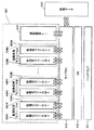
図1を参照して、開発支援装置は、当該開発支援装置のハードウェア501と、ハードウェア501を制御するコンピュータシステムを全体的に管理するOS(Operating System)502と、画像処理検査装置における具体的な処理内容を記述したプログラムからなる基本フロー507と、基本フロー507の各プログラムが参照するプログラムからなるライブラリ503とを含む。
Referring to FIG. 1, the development support apparatus includes a
基本フロー507は、画像処理検査装置における検査処理について、検査処理中にディスプレイに表示される画面の表示を制御する運転画面UI(User Interface)506と、当該検査処理に含まれる複数の処理段階のそれぞれの処理内容を制御するための画像処理モジュール(画像処理モジュールA509A〜画像処理モジュールN509N)とを含む。
The
画像処理モジュール509A〜509Nは、それぞれ、実際の処理内容を制御する処理モジュールMS(Measurement Structure)504A〜504Nと、各処理モジュールMSについての設定情報をディスプレイ(画像処理検査装置または開発支援装置のディスプレイ)に表示させるための処理モジュールUI(User Interface)505A〜505Nとを含む。
The
開発支援装置(または、画像処理検査装置)において、SIは、設定データ510に基づいて、基本フロー507を作成する。基本フロー507は、上記したように、運転画面UI506と複数の画像処理モジュール509A〜509Nを含む。開発支援装置では、(後述する画像処理モジュール記憶部291に)複数の画像処理モジュールが用意されている。SIは、それらの処理モジュールから、基本フロー507に組み込むべきものを選択するとともに、組み込む画像処理モジュールの処理モジュールMSに対して種々の値の設定を行なう。なお、SIは、処理モジュールMSに対する値等の設定を行なう場合、当該処理モジュールMSのソースコードを直接書き換えたり追加したりすることもできるし、ディスプレイに当該処理モジュールMSに対応した処理モジュールUIに基づく画面を表示させて当該画面を介して設定するべき値を入力することもできる。また、処理モジュールMSに対する値等の設定は、対応する画像処理モジュールが基本フローに組み込まれる前に行なうこともできる。
In the development support apparatus (or image processing inspection apparatus), the SI creates a
SIが処理モジュールUIを利用して処理モジュールMSの設定を行なうために、本実施の形態の開発支援装置では、画像処理モジュールとして、処理モジュールMSを作成するための素材(本明細書では、特に区別する必要がない場合には、処理モジュールUIを利用した設定が行なわれる前の状態の処理モジュールMSについても「処理モジュールMS」と呼ぶ)が予め準備されるとともに、各処理モジュールMSに対応した処理モジュールUIが準備されている。これにより、SIは、画像処理モジュールを作成する際(カスタマイズする際)に、処理モジュールMSにおけるプログラム(ソースコード)の記述を行なう代わりに処理モジュールUIに基づいて表示される画面に従って値(情報)を入力すればよくなる。処理モジュールUIに基づいた画面に従って情報が入力されることにより、処理モジュールMSを作成するための素材に対して適宜情報の書込みが行なわれ、これにより、SIが意図する処理モジュールMSが作成される。 Since the SI uses the processing module UI to set the processing module MS, the development support apparatus according to the present embodiment uses a material for creating the processing module MS as an image processing module (in this specification, in particular, If there is no need to distinguish between them, a processing module MS in a state before the setting using the processing module UI is also referred to as a “processing module MS”) is prepared in advance, and the processing module MS corresponds to each processing module MS. A processing module UI is prepared. Thereby, when creating (customizing) an image processing module, SI is a value (information) according to a screen displayed based on the processing module UI instead of describing a program (source code) in the processing module MS. You just need to enter When information is input according to a screen based on the processing module UI, information is appropriately written into the material for creating the processing module MS, thereby creating the processing module MS intended by the SI. .
本実施の形態の開発支援装置では、SIによる基本フローの作成の前に、処理モジュールMSの素材および当該処理モジュールMSに対応する処理モジュールUIが作成される。なお、処理モジュールMSは、後述するように、スケルトン形式で保存されているテンプレートに対して適宜情報の書換え(または、追加)が行なわれることにより、作成される。また、処理モジュールUIは、開発支援装置のハードディスク(後述するモジュール作成用データ記憶部25)に記憶された画像情報に適宜情報が追加されることにより作成される。
In the development support apparatus of the present embodiment, the material of the processing module MS and the processing module UI corresponding to the processing module MS are created before creating the basic flow by SI. As will be described later, the processing module MS is created by appropriately rewriting (or adding) information to a template stored in a skeleton format. The processing module UI is created by appropriately adding information to image information stored in the hard disk (module creation
開発支援装置において作成された基本フローは、ライブラリとともに、画像処理検査装置へインストールされる。画像処理検査装置では、基本フローを実行させることにより、部品の検査等の処理が実現される。なお、開発支援装置では、基本フローのソースコードが作成された場合、これに基づいて、開発支援装置と画像処理検査装置のそれぞれに対応したOS上で動作する基本フローが作成されることが好ましい。 The basic flow created in the development support apparatus is installed in the image processing inspection apparatus together with the library. In the image processing inspection apparatus, processing such as component inspection is realized by executing the basic flow. In the development support apparatus, when the source code of the basic flow is created, it is preferable to create a basic flow that operates on the OS corresponding to each of the development support apparatus and the image processing inspection apparatus. .
[開発支援装置のハードウェアの構成]
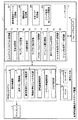
図2は、本発明の一実施の形態である開発支援装置のハードウェア構成を模式的に示す図である。開発支援装置1は、画像処理検査装置の画像処理機能をカスタマイズする装置であって、画像処理検査装置で動作する実行形式のプログラムを作成する。
[Hardware configuration of development support device]
FIG. 2 is a diagram schematically showing a hardware configuration of the development support apparatus according to the embodiment of the present invention. The
図2を参照して、本実施の形態の開発支援装置1は、汎用のコンピュータで実現されており、ディスプレイ2と、CPU(Central Processing Unit)およびメモリ4と、操作入力部7と、ハードディスク5と、リムーバブルメディア6を備える。
Referring to FIG. 2, the
操作入力部7は、マウス20とキーボード21を含み、開発支援装置1のユーザであるSIからの操作入力を受け付ける。なお、開発支援装置1では、SIによる操作とは別に、処理モジュールMSの素材等を作成する処理が実行される。操作入力部7は、このような処理における操作入力も受け付ける。
The
ハードディスク5は、カスタマイズプログラム記憶部14と、画像処理モジュール記憶部291と、基本フロー記憶部294と、イベント処理モジュール記憶部292と、運転画面記憶部293と、テンプレート記憶部16と、部品記憶部15と、OS類記憶部22と、ライブラリ類記憶部23と、シミュレーションソフト記憶部17と、マニュアル類記憶部18と、実行プログラム記憶部19と、モジュール作成用プログラム記憶部24と、モジュール作成用データ記憶部25とを含む。
The
カスタマイズプログラム記憶部14は、カスタマイズプログラム(Application Producer)を記憶する。カスタマイズプログラムは、CPUに読み込まれて実行され、コンピュータを画像処理機能の開発支援装置1の各構成要素として機能させる。
The customization
画像処理モジュール記憶部291は、ソースコード形式の画像処理モジュールを記憶する。画像処理モジュールは、色面積の計算、エッジ位置検出などの画像処理の基本単位を実行するためのもので、複数個のファイルからなる。そして、画像処理モジュール記憶部291は、出荷時に予め組み込まれている画像処理モジュールと、SIによって新たに作成された画像処理モジュールとを記憶する。
The image processing
画像処理モジュールは、画像処理結果の表示部分、画像処理結果の出力部分、画像処理の処理内容である演算部分、および画像処理のパラメータの設定のためのユーザインタフェース部分を少なくとも含む。画像処理のパラメータの設定には、サーチなどのモデル画像の領域座標および画像の設定、画像計測などの計測領域の設定、面積計測での穴埋め(輪郭の中を塗りつぶす)機能の実行の有無の設定、計測結果の判定を行なうための上下限値の設定などがある。 The image processing module includes at least an image processing result display part, an image processing result output part, an arithmetic part which is a processing content of the image processing, and a user interface part for setting image processing parameters. For image processing parameter settings, model image area coordinates and image settings such as search, measurement area settings such as image measurement, and whether or not to perform hole filling (filling the outline) function in area measurement There are upper and lower limit values for determining the measurement result.
また、上記したように、各画像処理モジュールは、画像処理の基本単位を実行するための部分(処理モジュールMS)とともに、当該基本単位の処理に対する各種の設定を行なうための画面を表示させるための部分(処理モジュールUI)を含む。 Further, as described above, each image processing module displays a screen for performing various settings for the processing of the basic unit, together with a portion (processing module MS) for executing the basic unit of image processing. Part (processing module UI).
基本フロー記憶部294は、SIによって作成された画像処理モジュールの実行順序と、そのパラメータからなる基本フローを記憶する。
The basic
イベント処理モジュール記憶部292は、SIによって新たに作成されたソースコード形式のイベント処理モジュールを記憶する。イベント処理モジュールは、画像処理検査装置による画像処理の実行中にイベントが発生した場合に、イベントが発生したタイミングで実行される処理を定めたものである。イベント処理モジュールは、画像処理モジュールのようなパラメータの設定のためのユーザインタフェース部分を含まない。
The event processing
運転画面記憶部293は、SIによって新たに作成された運転画面を記憶する。運転画面は、画像処理検査装置による画像処理の結果を表示するための画面であり、記憶されている運転画面は、ビジュアルベーシックのファイルからなる。
The operation
テンプレート記憶部16は、画像処理モジュールのテンプレートおよび運転画面のテンプレートを記憶する。
The
運転画面のテンプレートは、ビジュアルベーシック(登録商標)のファイルからなる。テンプレートとは、新たな画像処理モジュールおよび運転画面を作成するときの原型となるものであって、1個以上のファイルで構成され、ファイル内には、実行する典型的な呼び出し関数が記述されているものである。ファイル内の呼び出し関数には、典型的な実行命令が記述されていたり、あるいはリターン値だけが記載されていたりする。なお、このようなテンプレートのプログラムパターンを、本明細書では適宜スケルトン形式という。 The operation screen template includes a file of Visual Basic (registered trademark). A template is a prototype for creating a new image processing module and operation screen. The template is composed of one or more files, and a typical calling function to be executed is described in the file. It is what. In the calling function in the file, a typical execution instruction is described, or only a return value is described. Note that such a template program pattern is appropriately referred to as a skeleton format in this specification.
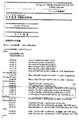
図3は、画像処理モジュールのテンプレートを構成するファイルの一覧とその機能の例を表わす図である。画像処理モジュール記憶部291に記憶されている画像処理モジュールも、「Sample」が個々の画像処理モジュール特有の名称となっている以外は、図3に示されたものと同様のファイル構成である。
FIG. 3 is a diagram showing a list of files constituting the template of the image processing module and an example of its function. The image processing module stored in the image processing
図3を参照して、「Sample_jpn.msg」は、日本語のメッセージファイルである。「Sample_eng.msg」は、英語のメッセージファイルである。 Referring to FIG. 3, “Sample_jpn.msg” is a Japanese message file. “Sample_eng.msg” is an English message file.
UIプログラム(処理モジュールUI)は、画像処理のパラメータ(各種の閾値など)を設定するためのユーザインタフェースを規定したものであり、2個の必須ファイルを含む。「NormalForm.vb」は、通常使用されるユーザインタフェースを記述したビジュアルベーシックのファイルである。「NonstopForm.vb」は、計測中に一時的に上下限値を変更するための簡易ノンストップをするときのユーザインタフェースを記述したビジュアルベーシックのファイルである。 The UI program (processing module UI) defines a user interface for setting image processing parameters (such as various threshold values), and includes two essential files. “NormalForm.vb” is a visual basic file describing a normally used user interface. “NonstopForm.vb” is a visual basic file describing a user interface for simple nonstop for temporarily changing the upper and lower limit values during measurement.
MSプログラム(処理モジュールMS)は、画像処理の処理内容である演算(つまり計測)、画像処理結果(つまり計測結果)の表示、画像処理結果(つまり計測結果)の出力などを規定したものであり、9個の必須ファイルと、5個の任意ファイルとを含む。MSプログラムのうち、どのファイルが画像処理モジュールの表示部分、出力部分、および演算(計測)部分のいずれに対応するかがファイル名によって識別可能とされている。これにより、SIがテンプレートを編集する際にどのファイルを修正すべきであるかが容易にわかる。また、MSプログラムのテンプレートに記述される関数は、その中身が戻り値(リターン値)だけが記述されているスケルトンの形式である。 The MS program (processing module MS) defines operations (that is, measurement) that are processing contents of image processing, display of image processing results (that is, measurement results), output of image processing results (that is, measurement results), and the like. , 9 essential files and 5 arbitrary files. Of the MS program, which file corresponds to the display part, the output part, and the calculation (measurement) part of the image processing module can be identified by the file name. This makes it easy to see which file should be modified when the SI edits the template. The function described in the template of the MS program has a skeleton format in which only the return value (return value) is described.
「AssignProc.cpp」は、処理ユニット登録時処理関連の処理を記述したテキストファイルである。処理ユニットは、画像処理モジュールと同義である。「Assign」は登録を意味し、「Proc」は処理を意味する「Processing」を略したものであるから、SIがテンプレートの編集の際に、「AssignProc.cpp」が上記処理を記述するものであることを容易に識別できる。
「FigureUpdate.cpp」は、図形データ更新時処理関連の処理を記述したテキストファイルである。「Figure」は図形を意味し、「Update」は更新を意味するものであるから、SIがテンプレートの編集の際に、「FigureUpdate.cpp」が上記処理を記述するものであることを容易に識別できる。
“AssignProc.cpp” is a text file describing processing related to processing at the time of processing unit registration. A processing unit is synonymous with an image processing module. “Assign” means registration, and “Proc” is an abbreviation for “Processing” which means processing, so when SI edits a template, “AssignProc.cpp” describes the above processing. It can be easily identified.
“FigureUpdate.cpp” is a text file that describes processing related to processing for updating graphic data. Since “Figure” means a figure and “Update” means an update, it is easy to identify that “FigureUpdate.cpp” describes the above processing when editing a template. it can.
「ItemDefs.h」は、処理項目の各種定義を記述したテキストファイルである。処理項目は、画像処理モジュールおよび処理ユニットと同義である。「「Item」は項目を意味し、「Def」は定義を意味する「Definition」を略したものであるから、SIがテンプレート
の編集の際に、「ItemDefs.h」が上記処理を記述するものであることを容易に識別できる。
“ItemDefs.h” is a text file describing various definitions of processing items. The processing item is synonymous with the image processing module and the processing unit. "" Item "means item and" Def "is short for" Definition "meaning definition, so when SI edits a template," ItemDefs.h "describes the above processing Can be easily identified.
「ItemInit.cpp」は、処理項目の初期化処理関連の処理を記述したテキストファイルである。「Item」は項目を意味し、「Init」は初期化を意味する「Initialization」を略したものであるから、SIがテンプレートの編集の際に、「ItemInit.cpp」が上記処理を記述するものであることを容易に識別できる。 “ItemInit.cpp” is a text file in which processing items related to initialization processing are described. "Item" means an item, and "Init" is an abbreviation for "Initialization" which means initialization, so when SI edits a template, "ItemInit.cpp" describes the above processing Can be easily identified.
「MeasureDisp.cpp」は、計測結果表示処理関連の処理を記述したテキストファイルで
ある。「Measure」は計測を意味し、「Disp」は表示を意味する「Display」を略したものであるから、SIがテンプレートの編集の際に、「MeasureDisp.cpp」が上記処理を記述
するものであることを容易に識別できる。
“MeasureDisp.cpp” is a text file describing processing related to measurement result display processing. “Measure” means measurement, and “Disp” is short for “Display”, which means display, so when SI edits a template, “MeasureDisp.cpp” describes the above processing. It can be easily identified.
「MeasureInit.cpp」は、計測初期化/終了関連の処理を記述したテキストファイルで
ある。「Measure」は計測を意味し、「Init」は初期化を意味する「Initialization」を
略したものであるから、SIがテンプレートの編集の際に、「MeasureInit.cpp」が上記
処理を記述するものであることを容易に識別できる。
“MeasureInit.cpp” is a text file describing processing related to initialization / end of measurement. "Measure" means measurement, and "Init" is short for "Initialization", which means initialization, so when SI edits a template, "MeasureInit.cpp" describes the above processing Can be easily identified.
「MeasureOut.cpp」は、計測結果出力処理関連の処理を記述したテキストファイルである。「Measure」は計測を意味し、「Out」は出力を意味するものであるから、SIがテンプレートの編集の際に、「MeasureOut.cpp」が上記処理を記述するものであることを容易に識別できる。 “MeasureOut.cpp” is a text file describing processing related to measurement result output processing. Since “Measure” means measurement and “Out” means output, it is easy to identify that “MeasureOut.cpp” describes the above processing when editing a template. it can.
「MeasureProc.cpp」は、計測処理関連の処理を記述したテキストファイルである。「Measure」は計測を意味し、「Proc」は処理を意味する「Processing」を略したものであるから、SIがテンプレートの編集の際に、「MeasureProc.cpp」が上記処理を記述するも
のであることを容易に識別できる。
“MeasureProc.cpp” is a text file describing processing related to measurement processing. “Measure” means measurement, and “Proc” is an abbreviation for “Processing” meaning processing, so when SI edits a template, “MeasureProc.cpp” describes the above processing. It can be easily identified.
「UnitData.cpp」は、処理ユニットデータ設定/取得関連の処理を記述したテキストファイルである。「Unit」はユニットを意味し、「Data」はデータを意味するものであるから、SIがテンプレートの編集の際に、「UnitData.cpp」が上記処理を記述するものであることを容易に識別できる。 “UnitData.cpp” is a text file describing processing unit data setting / acquisition related processing. “Unit” means a unit, and “Data” means data. Therefore, when editing a template, SI easily identifies that “UnitData.cpp” describes the above processing. it can.
「FigureData.cpp」、処理ユニットの図形データ操作関連の処理を記述したテキストファイルである。「Figure」は図形を意味し、「Data」はデータを意味するものであるから、SIがテンプレートの編集の際に、「FigureData.cpp」が上記処理を記述するものであることを容易に識別できる。 "FigureData.cpp" is a text file that describes the processing related to the figure data manipulation of the processing unit. Since “Figure” means a figure and “Data” means data, SI can easily identify that “FigureData.cpp” describes the above processing when editing a template. it can.
「RenumProc.cpp」は、処理ユニットの参照番号更新処理関連の処理を記述したテキス
トファイルである。「Renum」は番号更新を意味する「Renumber」を略したものであり、
「Proc」は処理を意味する「Processing」を略したものであるから、SIがテンプレートの編集の際に、「RenumProc.cpp」が上記処理を記述するものであることを容易に識別で
きる。
“RenumProc.cpp” is a text file that describes processing related to reference number update processing of the processing unit. "Renum" is short for "Renumber" meaning number update,
Since “Proc” is an abbreviation of “Processing” meaning processing, it can be easily identified that “RenumProc.cpp” describes the above processing when editing a template.
「SaveLoad.cpp」は、処理ユニットのデータのセーブおよびロード関連の処理を記述したテキストファイルである。「Save」セーブ(保存)を意味し、「Load」はロード(読出し)を意味するものであるから、SIがテンプレートの編集の際に、「SaveLoad.cpp」が上記処理を記述するものであることを容易に識別できる。 “SaveLoad.cpp” is a text file describing processing related to saving and loading data of the processing unit. "Save" means save, and "Load" means load (read). When SI edits a template, "SaveLoad.cpp" describes the above processing. Can be easily identified.
「SetupData.cpp」は、設定時の画像処理関連の処理を記述したテキストファイルであ
る。「Setup」は設定を意味し、「Data」はデータを意味するものであるから、SIがテ
ンプレートの編集の際に、「SetupData.cpp」が上記処理を記述するものであることを容
易に識別できる。
“SetupData.cpp” is a text file describing processing related to image processing at the time of setting. Since “Setup” means settings and “Data” means data, it is easy to identify that “SetupData.cpp” describes the above processing when editing a template. it can.
「ThroughProc.cpp」は、スルー表示のための画像入力および生成処理関連の処理を記
述したテキストファイルである。「Through」はスルー(直通)を意味し、「Proc」は処
理を意味する「Processing」を略したものであるから、SIがテンプレートの編集の際に、「ThroughProc.cpp」が上記処理を記述するものであることを容易に識別できる。
“ThroughProc.cpp” is a text file describing the image input and generation processing related processing for through display. “Through” means “through” and “Proc” is an abbreviation of “Processing” meaning processing, so when SI edits a template, “ThroughProc.cpp” describes the above processing Can be easily identified.
部品記憶部15は、画像処理モジュールのユーザインタフェースの画面のテンプレートおよび運転画面のテンプレートに貼り付けることができる部品(ActiveXコントロール)を記憶する。また、部品記憶部15は、イベント処理開発で利用する部品を記憶する。部品記憶部15に記憶されている部品は、表示されている画面に含まれるメニューのうちのツールから選択できる。
The
なお、出荷時の開発支援装置の画像処理モジュール記憶部291には、上記した各テンプレートに処理内容が記述されることによって作成された画像処理モジュールも記憶されている。このような画像処理モジュールには、上記した処理モジュールMSと処理モジュールUIが含まれる。
Note that the image processing
本実施の形態の開発支援装置では、SIは、基本フローを作成する際に、テンプレート記憶部16に記憶されたテンプレートに直接データを入力することによって作成した画像処理モジュールを基本フローに組み込んでも良いし、予め画像処理モジュール記憶部291に記憶された画像処理モジュール(上記した処理モジュールMSの素材と処理モジュールUIとを含む)を適宜カスタマイズして組み込んでも良い。なお、開発支援装置の出荷時(または、少なくともSIに操作される前であって画像処理モジュールの作成が行なわれた後)に記憶されている画像処理モジュールがどのように作成されるかについては、後述する。
In the development support apparatus according to the present embodiment, when creating a basic flow, SI may incorporate an image processing module created by directly inputting data into a template stored in the
OS類記憶部22は、Windows(登録商標)XPおよびVisualStudioを記憶する。
The
ライブラリ類記憶部23は、ライブラリおよびドライバを記憶する。
シミュレーションソフト記憶部17は、図1の画像処理機能の開発支援装置1で実行可能な実行形式のプログラムを起動するためのシミュレーションソフトを記憶する。
The
The simulation
マニュアル類記憶部18は、マニュアル、チュートリアル、ヘルプおよびサンプルを記憶する。
The
実行プログラム記憶部19は、出荷時に予め組み込まれている画像処理モジュールの実行形式のプログラム、およびビルド実行部13で作成された実行形式のプログラムを記憶する。
The execution
カスタマイズプログラム、部品、テンプレート、OS類、ライブラリ類、シミュレーションソフト、およびマニュアル類は、外部からリムーバブルメディア6を用いてハードディスク5にインストールすることができる。
The customization program, parts, templates, OSs, libraries, simulation software, and manuals can be installed on the
CPUおよびメモリ4は、OS類記憶部22からWindowsXPおよびVisualStudio(登録商標)を読出し、さらにカスタマイズプログラム記憶部14からカスタマイズプログラムを読み出して、これらを実行することによって、実行制御部8、基本フロー開発部9、画像処理モジュール開発部10、運転画面開発部11、イベント処理開発部12、および、ビルド実行部13として機能する。また、CPUおよびメモリ4は、OS類記憶部22からWindowsXPおよびVisualStudio(登録商標)を読出し、さらにモジュール作成用プログラム記憶部24から画像モジュール作成用プログラムを読み出し、これらを実行することによって、画像処理モジュール作成部10Aとして機能する。
The CPU and the
実行制御部8は、この画像処理機能の開発支援装置1の全体の動作を制御する。
基本フロー開発部9は、操作入力部7を通じたユーザの操作に従って、画像処理モジュール記憶部291に記憶されている複数個の画像処理モジュールの実行順序を決定して、決定した実行順序と、そのパラメータからなる基本フローを基本フロー記憶部294に記憶する。
The
The basic
画像処理モジュール開発部10は、テンプレート記憶部16に記憶されている画像処理モジュールのテンプレートを読み出して表示し、操作入力部7を通じたSIの操作に従って、画像処理モジュールのテンプレートを編集して、編集後の画像処理モジュールを画像処理モジュール記憶部291に記憶する。
The image processing
また、画像処理モジュール開発部10は、画像処理モジュール記憶部291に記憶されている処理モジュールUIに対応した画面を表示させ、そして、当該画面に対応して入力された情報を当該処理モジュールUIに対応する処理モジュールMSの素材に書込むことにより、画像処理モジュールのカスタマイズを行なう。カスタマイズされた画像処理モジュールは、画像処理モジュール記憶部291に記憶される。
Further, the image processing
画像処理モジュール作成部10Aは、SIが利用する処理モジュールUIおよび当該処理モジュールUIを利用して入力された情報によって作成(編集)が可能な処理モジュールMSの素材を作成する。処理モジュールUIの作成は、モジュール作成用データ記憶部25に記憶された画像情報が適宜変更することによって行なわれ、処理モジュールMSの素材は、テンプレート記憶部16に記憶されている処理モジュールMSのテンプレートを編集することによって行なわれる。
The image processing
運転画面開発部11は、テンプレート記憶部16に記憶されている運転画面のテンプレートを読み出して表示し、操作入力部7を通じたSIの操作に従って、運転画面のテンプレートに部品記憶部15に記憶されている部品を貼り付けて運転画面のテンプレートを編集して、編集後の運転画面を運転画面記憶部293に記憶する。
The operation
イベント処理開発部12は、操作入力部7を通じたSIの操作に従って、イベントモジュールを作成して、イベント処理モジュール記憶部292に記憶する。
The event
ビルド実行部13は、ソースコードをコンパイルしてオブジェクトコードを生成し、さらにオブジェクトコードとライブラリ類記憶部23内のライブラリおよびドライバとをリンクすることによって、実行形式のプログラムを作成して実行プログラム記憶部19に記憶する。ビルド実行部13は、画像処理検査装置が動作するOSであるWindows(登録商標)CE用の実行形式のプログラムと、図1の画像処理機能の開発支援装置1が動作するOSであるWindowsXP用の実行形式のプログラムの両方を作成する。WindowsCE用の実行形式のプログラムは、リムーバブルメディア6などを用いて、画像処理検査装置にインストールされる。WindowsXP用の実行形式のプログラムは、図1の装置で、画像処理検査装置におる画像処理をエミュレート(シミュレーション)するために用いられる。
The
CPUおよびメモリ4から出力される画面データは、ディスプレイ2に送られて表示される。
The screen data output from the CPU and the
[SIによる基本フローの作成]
本実施の形態の開発支援装置では、SIが、操作入力部7に対して適宜操作を行なうことにより、基本フロー開発部9は、ディスプレイ2に、図4に示されるような画面(基本フロー開発用画面)を表示する。
[Create basic flow by SI]
In the development support apparatus according to the present embodiment, when the SI appropriately operates the
図4を参照して、基本フロー開発用画面は、画像処理モジュールのリストが表示されるリスト欄83と、基本フローにおける画像処理モジュールの順序を示す基本フロー欄95を含む。画像処理モジュール記憶部291では、各画像処理モジュールは用途に応じた種別ごとに分類されて記憶されている。ここでの種別には、「検査・計測する」「画像を取り込む」「画像を補正する」「検査・計測を補助する」を含む。そして、リスト欄83では、各画像処理モジュールの名称が、これらの種別に従って表示されている。
Referring to FIG. 4, the basic flow development screen includes a
以下、基本フロー開発用画面を用いた基本フローの作成について説明する。
SIが、マウス20を操作してリスト欄83の一つの項目を選択すると、基本フロー開発部9は、リスト欄83の中の1つの画像処理モジュールを選択する。
Hereinafter, creation of a basic flow using the basic flow development screen will be described.
When the SI operates the
SIが、マウス20を操作して追加ボタン84を選択すると、基本フロー開発部9は、基本フロー欄95の最下部にリスト欄83で選択されている画像処理モジュールを追加する。
When the SI operates the
SIが、マウス20を操作して挿入ボタン85を選択すると、基本フロー開発部9は、基本フロー欄95の中の選択されている画像処理モジュールの直下にリスト欄83で選択されている画像処理モジュールを挿入する。
When the SI operates the
SIが、マウス20を操作して設定ボタン86を選択すると、画像処理モジュール開発部10は、基本フローの中の選択されている画像処理モジュール(の処理モジュールMS)のパラメータなどを設定するためのUIプログラムを画像処理モジュール記憶部291から読み出して表示する。SIが、表示されている画面に含まれるメニューのうちのツールから部品を選択し、部品記憶部15から選択された部品を読み出して配置することによって、ユーザインタフェース画面が編集され、図示しない保存メニューを選択して、編集後のUIプログラムが画像処理モジュール記憶部291に記憶される。
When the SI operates the
SIが、マウス20を操作してコピーボタン90を選択すると、基本フロー開発部9は、基本フロー欄95の中の選択されている画像処理モジュールをコピーする。
When the SI operates the
SIが、マウス20を操作してペーストボタン91を選択すると、基本フロー開発部9は、基本フロー欄95の中の選択されている画像処理モジュールの直下に、コピーボタン90によってコピーした画像処理モジュールを挿入する。
When the SI operates the
SIが、マウス20を操作して削除ボタン92を選択すると、基本フロー開発部9は、基本フロー欄95の中の選択されている画像処理モジュールを削除する。
When the SI operates the
SIが、マウス20を操作して移動(上へ)ボタン88を選択すると、基本フロー開発部9は、基本フロー欄95の中の選択される画像処理モジュールを1つ上に移動する。
When the SI operates the
SIが、マウス20を操作して移動(下へ)ボタン89を選択すると、基本フロー開発部9は、基本フロー欄95の中の選択される画像処理モジュールを1つ下に移動する。
When the SI operates the
SIが、マウス20を操作して名前の変更ボタン87を選択すると、基本フロー開発部9は、基本フロー欄95の中の選択されている画像処理モジュールの名前の変更を可能とする。SIは、キーボード21を操作することにより、画像処理モジュールの名前を入力することができる。
When the SI operates the
SIが、マウス20を操作してヘルプ96を選択すると、基本フロー開発部9は、マニュアル類記憶部18からヘルプを読み出して表示するる。
When the SI operates the
SIが、マウス20を操作して閉じる97を選択すると、基本フロー開発部9は、基本フローが作成されている場合に、作成された基本フローを基本フロー記憶部294に記憶し、その処理を終了する。
When the SI selects 97 to close by operating the
図5は、基本フローの作成後の画面の例を表わす図である。
図5を参照して、基本フローは、3つの画像処理モジュール98、99、40からなる。この基本フローでは、まずカメラ画像を入力し、次に入力した画像の面積重心を計算して、その後画像処理モジュールのデータを設定することを定めた基本フローが作成されている。
FIG. 5 is a diagram illustrating an example of a screen after creation of the basic flow.
Referring to FIG. 5, the basic flow includes three
[SIによる画像処理モジュールの作成]
次に、本実施の形態の開発支援装置における、SIがテンプレート記憶部16に記憶されたテンプレートを用いて画像処理モジュールを作成する処理について説明する。
[Create image processing module using SI]
Next, a process of creating an image processing module using a template whose SI is stored in the
図6は、SIが画像処理モジュールの作成を行なう際にディスプレイ2に表示される画面の一例を示す図である。図7は、画像処理モジュール開発の処理手順を表わすフローチャートである。
FIG. 6 is a diagram illustrating an example of a screen displayed on the
SIが操作入力部7を適宜操作することにより画像処理モジュールを作成するプログラムを起動させると、ディスプレイ2には図6に示された画面が表示される。そして、さらに図7を参照して、SIが、当該画像に対して、マウス20を操作してボタン65を選択したときには(ステップS401でYES)、画像処理モジュール開発部10は、MSプログラムの編集処理を選択し、MSプログラムのテンプレート41をテンプレート記憶部16から読み出して、図8に示すようにエディタ上に表示する。SIが、キーボートから文字を入力、削除することによって、MSプログラムのテンプレート41を編集して、図示しない保存メニューを選択して、編集後のMSプログラムを画像処理モジュール記憶部291に記憶する(ステップS402)。
When the SI starts the program for creating the image processing module by appropriately operating the
SIが、マウス20を操作してボタン66を選択したときには(ステップS403でYES)、画像処理モジュール開発部10は、マニュアル類記憶部18からMSプログラムの編集を説明したマニュアル3−2−5章を読み出して表示する(ステップS404)。
When the SI operates the
SIが、マウス20を操作してボタン67を選択したときには(ステップS405でYES)、画像処理モジュール開発部10は、UIプログラムの編集処理を選択して、UIプログラムのテンプレートをテンプレート記憶部16から読み出して図9に示すようなユーザインタフェース画面のテンプレート461を表示する。SIが、表示されている画面に含まれるメニューのうちのツール462から部品を選択し、部品記憶部15から選択された部品を読み出して配置することによって、図9のユーザインタフェース画面のテンプレート461を編集し、図示しない保存メニューを選択して、編集後のUIプログラムを画像処理モジュール記憶部291に記憶する(ステップS406)。
When the SI selects the
SIが、マウス20を操作してボタン68を選択したときには(ステップS407でYES)、画像処理モジュール開発部10は、マニュアル類記憶部18からUIプログラムの編集を説明したマニュアル3−2−6章を読み出して表示する(ステップS408)。
When the SI operates the
SIが、マウス20を操作してボタン69を選択したときには(ステップS409でYES)、画像処理モジュール開発部10は、マニュアル類記憶部18からユーザインタフェース画面のサンプルを読み出して表示する(ステップS410)。
When the SI selects the
SIが、マウス20を操作してボタン70を選択したときには(ステップS411でYES)、実行制御部8は、シミュレーションソフト記憶部17からシミュレーションソフトを読み出して起動する(ステップS412)。
When the SI operates the
SIが、マウス20を操作してボタン71を選択したときには(ステップS413でYES)、画像処理モジュール開発部10は、マニュアル類記憶部18から画像処理モジュール開発のチュートリアルを読み出して表示する(ステップS414)。
When the SI selects the
SIが、マウス20を操作してボタン72を選択したときには(ステップS415でYES)、画像処理モジュール開発部10は、マニュアル類記憶部18から画像処理モジュール開発を説明したマニュアル3−2章を読み出して表示する(ステップS416)。
When the SI operates the
SIが、マウス20を操作してボタン73を選択したときには(ステップS417でYES)、画像処理モジュール開発部10は、マニュアル類記憶部18から画像処理モジュール開発のためのリファレンスを読み出して表示する(ステップS418)。
When the SI selects the
SIが、マウス20を操作して図示しないビルドメニューを選択したときには(ステップS419でYES)、ビルド実行部13は、画像処理モジュール記憶部291に記憶されているステップS402で作成されたMSのソースコードおよびステップS406で作成されたUIのソースコードをコンパイルしてオブジェクトコードを生成し、ライブラリ類記憶部23から必要なライブラリとドライバを読み出してオブジェクトコードとリンクすることによって、WindowsCEとWindowsXP用のMSの実行形式のプログラムおよびUIの実行形式のプログラムを作成して実行プログラム記憶部19に記憶する(ステップS420)。
When the SI selects the build menu (not shown) by operating the mouse 20 (YES in step S419), the
SIが、マウス20を操作して図示しない「戻る」ボタンを選択したときには(ステップS421でYES)、画像処理モジュール開発部10は、処理を終了する。
When the SI operates the
次に、テンプレートがSIの編集によってどのように変更されるかの例を説明する。ここでは、テンプレートを編集して、他の画像処理モジュールのパラメータ設定を一括して行なうための画像処理モジュールを作成する場合について説明する。この画像処理モジュールは、座標の変更や上下限値の変更などのように、複数の数値を変更する場合に用いられる。 Next, an example of how the template is changed by editing the SI will be described. Here, a case will be described in which an image processing module is created for editing a template and collectively setting parameters of other image processing modules. This image processing module is used when a plurality of numerical values are changed, such as a change in coordinates or a change in upper and lower limit values.
図10および図11は、「ItemDefs.h」のテンプレートを表わす図である。
図12および図13は、編集後の「ItemDefs.h」を表わす図である。
10 and 11 are diagrams showing a template of “ItemDefs.h”.
12 and 13 are diagrams showing “ItemDefs.h” after editing.
図10〜図13を参照して、SIの編集によって、テンプレートの定義文190が、定義文191に変更され、定義文192、193、194が追加されている。
Referring to FIGS. 10 to 13,
図10〜図13を参照して、「ItemDefs.h」の内容を説明する。SETUPDATA構造体には、処理を実行する際に必要になるパラメータなどの設定データの構造が定義される。MEASUREDATA構造体には、処理(計測)を実行した際の結果のデータの構造が定義される。ItemDef.h中で定義した SETUPDATA構造体に含まれるデータの初期値については、AssignProc.cpp中に記述される。 The contents of “ItemDefs.h” will be described with reference to FIGS. In the SETUPDATA structure, a structure of setup data such as parameters necessary for executing processing is defined. The MEASUREDATA structure defines the data structure of the result when processing (measurement) is executed. The initial value of the data contained in the SETUPDATA structure defined in ItemDef.h is described in AssignProc.cpp.
図14は、「AssignProc.cpp」のテンプレートを表わす図である。
図15および図16は、編集後の「AssignProc.cpp」を表わす図である。
FIG. 14 shows a template of “AssignProc.cpp”.
15 and 16 are diagrams showing “AssignProc.cpp” after editing.
図14〜図16を参照して、SIの編集によって、日付151が記入され、作成者152が記入され、関数AssignProcの中身の命令153が追加されている。
Referring to FIGS. 14 to 16, by editing SI,
図14〜図16を参照して、「AssignProc.cpp」の内容を説明する。本ファイル内では以下の関数の処理を定義し、画像処理モジュールが登録される際のチェック処理などを記述する。 The contents of “AssignProc.cpp” will be described with reference to FIGS. In this file, processing of the following functions is defined, and check processing when an image processing module is registered is described.
int クラス名::AssignProc(*ptrProcUnit);
ProcUnit *ptrProcUnit; 処理ユニット情報へのポインタ
本関数の処理を終了する際は、戻り値として以下の値を返す。NORMAL以外の値を返した場合は処理ユニット登録不可ということで、処理ユニットの登録が行われない。
int class name :: AssignProc (* ptrProcUnit);
ProcUnit * ptrProcUnit; Pointer to processing unit information When the processing of this function is terminated, the following values are returned as return values. If a value other than NORMAL is returned, processing unit registration is not possible, so processing unit registration is not performed.
NORMAL(0):処理ユニット登録可能
!NORMAL(0以外):処理ユニット登録不可
設定データの初期化は、このメソッドに記述し、図形データの初期化(SetFigureType())は、このメソッドに記述する。本関数を用いることで、処理ユニットの登録順序などに制約がある場合のチェックを行なうことができる。
NORMAL (0): Processing unit can be registered
! NORMAL (other than 0): Processing unit registration not possible Set data initialization is described in this method, and figure data initialization (SetFigureType ()) is described in this method. By using this function, it is possible to check when there is a restriction in the registration order of processing units.
図17および図18は、「FigureUpdate.cpp」のテンプレートを表わす図である。
本発明の実施形態では、SIが、テンプレートを編集しなかったため、「FigureUpdate.cpp」は、変更されていない。
17 and 18 are diagrams showing a template of “FigureUpdate.cpp”.
In the embodiment of the present invention, “FigureUpdate.cpp” is not changed because SI did not edit the template.
図17および図18を参照して、「FigureUpdate.cpp」の内容を説明する。本ファイル内では以下のメソッドを記述し、図形データが更新されたときの処理を記述する。 The contents of “FigureUpdate.cpp” will be described with reference to FIGS. 17 and 18. The following methods are described in this file, and the processing when graphic data is updated is described.
int クラス名::FigureUpdate(*ptrProcUnit, figureNo);
ProcUnit *ptrProcUnit; 処理ユニット情報へのポインタ
int figureNo; 図形データ番号
本関数の処理を終了する際は、戻り値として以下の値を返す。
int class name :: FigureUpdate (* ptrProcUnit, figureNo);
ProcUnit * ptrProcUnit; Pointer to processing unit information
int figureNo; Figure data number When this function is finished, the following values are returned.
NORMAL(0):図形データ更新処理に成功
!NORMAL(0以外):図形データ更新処理に失敗
モデルの登録処理は本メソッドに記述する。
NORMAL (0): Successful graphic data update processing
! NORMAL (other than 0): Graphic data update processing failed Model registration processing is described in this method.
図19および図20は、「ItemInit.cpp」のテンプレートを表わす図である。
図21および図22は、編集後の「ItemInit.cpp」を表わす図である。
19 and 20 are diagrams showing a template of “ItemInit.cpp”.
21 and 22 are diagrams showing “ItemInit.cpp” after editing.
図19〜図22を参照して、SIの編集によって、日付154が記入され、作成者155が記入されている。さらに、SIの編集によって、テンプレートの"Sample"658、ITEM_MEASURE659、一般計測関連660、0(661)、"サンプル"662が、"SetUnitData4"158、ITEM_SUPPORT159、計測補助関連160、4(161)、"処理ユニッ
トデータ設定"162に変更されている。
Referring to FIG. 19 to FIG. 22, the
図19〜図22を参照して、「ItemInit.cpp」の内容を説明する。コンストラクタ・デストラクタおよび本クラスのインスタンスを生成する関数、本クラスのインスタンスを削除する関数を記述する。なお、本クラスのインスタンスを生成する関数および本クラスのインスタンスを削除する関数は、DLLのエクスポート関数にする。コンストラクタには画
像処理モジュールをシステム(CORERA)に認識させるための情報を記述する。具体的には下記のメソッドに値を設定する。
The contents of “ItemInit.cpp” will be described with reference to FIGS. 19 to 22. Write a constructor / destructor, a function that creates an instance of this class, and a function that deletes an instance of this class. The functions that generate instances of this class and the functions that delete instances of this class are DLL export functions. In the constructor, information for making the system (CORERA) recognize the image processing module is described. Specifically, set the value to the following method.
this->itemIdent = _T("Sample"); (A) 画像処理モジュール識別名
this->maker = _T("OMRON AST3"); (B) 画像処理モジュール製作者名
this->version = 100; (C) バージョン番号(×100)
this->itemKind = ITEM_MEASURE; (D) 画像処理モジュール種別(=一般計測関連)
this->setupDataSize = sizeof(SETUPDATA); (E)設定データ構造体サイズ
this->measureDataSize = sizeof(MEASUREDATA); (F) 計測データ構造体サイズ
this->modelDataCount = 0; (G) モデルデータ最大個数
this->imageDataCount = 0; (H) 画像データ最大個数
this->innerUnitCount = 0;(I) 内包処理ユニット最大個数
this->figureDataCount = 0;(J) 図形データ最大個数
this->title = _T("サンプル"); (K) 画像処理モジュールタイトル名
デストラクタには、本クラスのインスタンスが消滅するときに実行する処理を記述する。本関数では、本クラスのインスタンスを生成し戻り値として返す処理を記述する。本関数の処理を終了する際は、戻り値として以下の値を返す。なお、図20中の記述991Nについては後述する。
this-> itemIdent = _T ("Sample"); (A) Image processing module identification name
this-> maker = _T ("OMRON AST3"); (B) Image processing module manufacturer name
this-> version = 100; (C) Version number (× 100)
this-> itemKind = ITEM_MEASURE; (D) Image processing module type (= General measurement related)
this-> setupDataSize = sizeof (SETUPDATA); (E) Setup data structure size
this-> measureDataSize = sizeof (MEASUREDATA); (F) Measurement data structure size
this-> modelDataCount = 0; (G) Maximum number of model data
this-> imageDataCount = 0; (H) Maximum number of image data
this-> innerUnitCount = 0; (I) Maximum number of included processing units
this-> figureDataCount = 0; (J) Maximum number of figure data
this-> title = _T ("Sample"); (K) Image processing module title name Destructor describes the processing to be executed when this class instance disappears. This function describes the process of creating an instance of this class and returning it as a return value. When the processing of this function ends, the following values are returned as return values. The description 991N in FIG. 20 will be described later.
ProcItem:インスタンスのポインタ:インスタンス生成成功時
NULL:インスタンス生成失敗時
図23および図24は、「MeasureDisp.cpp」のテンプレートを表わす図である。
ProcItem: Instance pointer: When instance creation is successful
NULL: When instance generation fails FIG. 23 and FIG. 24 are diagrams showing a template of “MeasureDisp.cpp”.
図25〜図27は、編集後の「MeasureDisp.cpp」を表わす図である。
図23および図24および図25〜図27を参照して、SIの編集によって、日付163および日付164が記入され、作成者165および作成者166が記入され、関数MeasureDispTの中身の命令167が追加されている。
25 to 27 are diagrams showing “MeasureDisp.cpp” after editing.
Referring to FIG. 23, FIG. 24, and FIG. 25 to FIG. 27, the date 163 and
本ファイル内では以下のメソッドを記述し、画像処理モジュール個別に計測結果を表示する際の表示処理を記述する。 The following method is described in this file, and the display processing when displaying the measurement result for each image processing module is described.
int クラス名::MeasureDispI(*ptrProcUnit, subNo, *ptrImageWindow);
void クラス名::MeasureDispG(*ptrProcUnit, subNo, *ptrImageWindow);
ProcUnit *ptrProcUnit; 処理ユニット情報へのポインタ
int subNo; 表示種別の番号
ImageWindow *ptrImageWindow; 画像表示エリア情報へのポインタ
void クラス名::MeasureDispT(*ptrProcUnit, subNo, *ptrTextWindow);
ProcUnit *ptrProcUnit; 処理ユニット情報へのポインタ
int subNo; 表示種別の番号
TextWindow *ptrTextWindow; 詳細結果表示エリア情報へのポインタ
本関数の処理を終了する際は、戻り値として以下の値を返す。
int class name :: MeasureDispI (* ptrProcUnit, subNo, * ptrImageWindow);
void class name :: MeasureDispG (* ptrProcUnit, subNo, * ptrImageWindow);
ProcUnit * ptrProcUnit; Pointer to processing unit information
int subNo; Display type number
ImageWindow * ptrImageWindow; Pointer to image display area information
void class name :: MeasureDispT (* ptrProcUnit, subNo, * ptrTextWindow);
ProcUnit * ptrProcUnit; Pointer to processing unit information
int subNo; Display type number
TextWindow * ptrTextWindow; Pointer to detailed result display area information When this function is finished, the following values are returned as return values.
NORMAL(0):計測結果出力処理正常終了
!NORMAL(0以外):計測結果出力処理異常終了
3つの関数は、以下の記述に対応する。
NORMAL (0): Measurement result output processing ends normally
! NORMAL (other than 0): Measurement result output process abnormal termination The three functions correspond to the following descriptions.
MeasureDispI():画像表示
MeasureDispG():画像表示エリアへのグラフィック表示
MeasureDispT():詳細結果表示エリアへの文字表示
引数subNoが-1の場合は、全画像処理モジュール共通で位置一覧表示モード時の表示と
なる。サーチ系の画像処理モジュールの場合は、モデル領域のみ表示する。処理ユニットの判定結果が”判定なし”の場合(MEASDATA 構造体中のjudge=J_NCの場合)、処理ユニ
ットのMeasureDisp*()はコールされない。
MeasureDispI (): Image display
MeasureDispG (): Graphic display in the image display area
MeasureDispT (): Character display in the detailed result display area When the argument subNo is -1, the display is in the position list display mode common to all image processing modules. In the case of a search-type image processing module, only the model area is displayed. When the judgment result of the processing unit is “no judgment” (when judge = J_NC in the MEASDATA structure), MeasureDisp * () of the processing unit is not called.
図28および図29は、「MeasureInit.cpp」のテンプレートを表わす図である。
本発明の実施形態では、SIが、テンプレートを編集しなかったため、「MeasureInit.cpp」が変更されていない。
28 and 29 are diagrams showing a template of “MeasureInit.cpp”.
In the embodiment of the present invention, since SI does not edit the template, “MeasureInit.cpp” is not changed.
図28および図29を参照して、「MeasureInit.cpp」の内容を説明する。本ファイル
内では、以下の関数の処理を定義し、計測画面に入る時点で実行すべき初期化処理および計測終了時に実行すべき処理を記述する。
The contents of “MeasureInit.cpp” will be described with reference to FIG. 28 and FIG. 29. In this file, the processing of the following functions is defined, and the initialization processing to be executed when entering the measurement screen and the processing to be executed at the end of measurement are described.
int クラス名::MeasureInit(*ptrProcUnit);
int クラス名::MeasureEnd(*ptrProcUnit);
ProcUnit *ptrProcUnit; 処理ユニット情報へのポインタ
本関数の処理を終了する際は、戻り値として以下の値を返す。
int class name :: MeasureInit (* ptrProcUnit);
int class name :: MeasureEnd (* ptrProcUnit);
ProcUnit * ptrProcUnit; Pointer to processing unit information When the processing of this function is terminated, the following values are returned as return values.
NORMAL(0):計測初期化処理正常終了
!NORMAL(0以外):計測初期化処理異常終了
NORMAL以外の値を返した場合は画面にエラーメッセージが表示され、当該シーン内の全処理ユニットの非セーブROIモデルがクリアされる。また、NORMAL以外の値を返して画面にエラーメッセージが表示された場合も、メッセージボックスを終了するとそのまま計測が実行可能な状態になる。
NORMAL (0): Measurement initialization process completed normally
! NORMAL (other than 0): Measurement initialization process abnormal termination
If a value other than NORMAL is returned, an error message is displayed on the screen, and the non-save ROI models of all the processing units in the scene are cleared. Also, if an error message is displayed on the screen after returning a value other than NORMAL, the measurement can be executed as it is when the message box is terminated.
図30は、「MeasureOut.cpp」のテンプレートを表わす図である。
本発明の実施形態では、SIが、テンプレートを編集しなかったため、「MeasureOut.cpp」が変更されていない。
FIG. 30 shows a template for “MeasureOut.cpp”.
In the embodiment of the present invention, since SI does not edit the template, “MeasureOut.cpp” is not changed.
図30を参照して、「MeasureOut.cpp」の内容を説明する。本ファイル内では以下のメソッドを記述し、画像処理モジュール個別に計測結果を出力する際の結果出力処理を記述する。 The contents of “MeasureOut.cpp” will be described with reference to FIG. The following method is described in this file, and the result output process when outputting the measurement result for each image processing module is described.
int クラス名::MeasureOut(*ptrProcUnit);
ProcUnit *ptrProcUnit; 処理ユニット情報へのポインタ
本関数の処理を終了する際は、戻り値として以下の値を返す。
int class name :: MeasureOut (* ptrProcUnit);
ProcUnit * ptrProcUnit; Pointer to processing unit information When the processing of this function is terminated, the following values are returned as return values.
NORMAL(0):計測結果出力処理正常終了
!NORMAL(0以外):計測結果出力処理異常終了
図31は、「MeasureProc.cpp」のテンプレートを表わす図である。
NORMAL (0): Measurement result output processing ends normally
! NORMAL (other than 0): Measurement result output process abnormal termination FIG. 31 is a diagram showing a template of “MeasureProc.cpp”.
図32〜図34は、編集後の「MeasureProc.cpp」を表わす図である。
図31および図32〜図34を参照して、SIの編集によって、日付168が記入され、作成者169が記入され、関数MeasureProcの中身の命令170が追加されている。
32 to 34 are diagrams showing “MeasureProc.cpp” after editing.
Referring to FIG. 31 and FIGS. 32 to 34, the
図31および図32〜図34を参照して、「MeasureProc.cpp」の内容を説明する。本ファイル内では以下のメソッドを記述し、計測時に実行する画像処理などの処理を記述する。 The contents of “MeasureProc.cpp” will be described with reference to FIG. 31 and FIGS. Describe the following methods in this file, and describe processing such as image processing to be executed during measurement.
int クラス名::MeasureProc(*ptrProcUnit);
ProcUnit *ptrProcUnit; 処理ユニット情報へのポインタ
本関数の処理を終了する際は、戻り値として以下の値を返す。
int class name :: MeasureProc (* ptrProcUnit);
ProcUnit * ptrProcUnit; Pointer to processing unit information When the processing of this function is terminated, the following values are returned as return values.
NORMAL(0):計測処理正常終了
!NORMAL(0以外):計測処理異常終了
図35および図36は、「RenumProc.cpp」のテンプレートを表わす図である。
NORMAL (0): Measurement processing ends normally
! NORMAL (other than 0): abnormal termination of measurement processing FIGS. 35 and 36 are diagrams showing a template of “RenumProc.cpp”.
図37および図38は、編集後の「RenumProc.cpp」を表わす図である。
図35〜図38を参照して、SIの編集によって、日付171が記入され、作成者172が記入され、関数RenumProcの中身の命令173が追加されている。
FIG. 37 and FIG. 38 are diagrams showing “RenumProc.cpp” after editing.
With reference to FIGS. 35 to 38, the
図35〜図38を参照して、「RenumProc.cpp」の内容を説明する。本ファイル内では以下のメソッドを記述し、ユニット追加・削除・移動時の処理を記述する。 The contents of “RenumProc.cpp” will be described with reference to FIGS. Describe the following methods in this file, and describe the processing when adding, deleting, and moving units.
int クラス名::RenumProc(*ptrProcUnit, *ptrRenumInfo);
ProcUnit *ptrProcUnit; 処理ユニット情報へのポインタ
RenumInfo *ptrRenumInfo;フロー編集情報へのポインタ
本関数の処理を終了する際は、戻り値として以下の値を返す。
int class name :: RenumProc (* ptrProcUnit, * ptrRenumInfo);
ProcUnit * ptrProcUnit; Pointer to processing unit information
RenumInfo * ptrRenumInfo; Pointer to flow editing information When this function is finished, the following values are returned as return values.
NORMAL(0):ユニット追加・削除・移動時処理正常終了
!NORMAL(0以外):ユニット追加・削除・移動時処理異常終了
図39〜図41は、「UnitData.cpp」のテンプレートを表わす図である。
NORMAL (0): Normal completion of processing when adding, deleting, or moving units
! NORMAL (other than 0): abnormal end of unit addition / deletion / movement process FIGS. 39 to 41 are diagrams showing templates of “UnitData.cpp”.
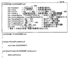
図42〜図50は、編集後の「UnitData.cpp」を表わす図である。
図39〜図41および図42〜図50を参照して、SIの編集によって、マクロ定義に関する定義文174が追加され、静的変数に関する定義文175が追加され、関数参照に関する定義文176が追加されている。関数SetUnitData(ptrProcUnit, dataNo, data)に関して、日付177が記入され、作成者178が記入され、中身の命令179が追加されている。関数SetUnitData(ptrProcUnit, dataIdent, data)に関して、日付180が記入され、作成者181が記入され、中身の命令182が追加されている。関数GetUnitData(ptrProcUnit, dataNo, data)に関して、日付183が記入され、作成者184が記入され、中身の命令185が追加されている。関数GetUnitData(ptrProcUnit, dataIdent, data)に関して、日付186が記入され、作成者187が記入され、中身の命令188が追加されている。さらに、関数setDataProcおよび関数getDataProcが追加されている。
42 to 50 are diagrams showing “UnitData.cpp” after editing.
Referring to FIGS. 39 to 41 and FIGS. 42 to 50, by editing SI,
図39〜図41および図42〜図50を参照して、「UnitData.cpp」の内容を説明する。 The contents of “UnitData.cpp” will be described with reference to FIGS. 39 to 41 and FIGS. 42 to 50.
本ファイル内では以下のメソッドを記述し、データ設定時およびデータ取得時の処理を記述する。 The following methods are described in this file, and the process at the time of data setting and data acquisition is described.
int クラス名::SetUnitData(*ptrProcUnit, dataNo, *data);
ProcUnit *ptrProcUnit; 処理ユニット情報へのポインタ
int datano; 設定するデータのデータ番号
ANYTYPE *data; 設定するデータ
int クラス名::SetUnitData(*ptrProcUnit, dataIdent, *data);
ProcUnit *ptrProcUnit; 処理ユニット情報へのポインタ
TCHAR *dataIdent; 設定するデータの識別文字列へのポインタ
ANYTYPE *data; 設定するデータ
int クラス名::GetUnitData(*ptrProcUnit, dataNo, *data);
ProcUnit *ptrProcUnit; 処理ユニット情報へのポインタ
int datano; 取得するデータのデータ番号
ANYTYPE *data; 取得するデータ
int クラス名::GetUnitData(*ptrProcUnit, dataIdent, *data);
ProcUnit *ptrProcUnit; 処理ユニット情報へのポインタ
TCHAR *dataIdent; 取得するデータの識別文字列へのポインタ
ANYTYPE *data; 取得するデータ
ANYTYPE データタイプ構造体定義
typedef struct {
int type;
int ival;
double dval;
TCHAR *string;
struct {
void *addr;
int size;
} variant;
} ANYTYPE;
上記のtypeには以下のようにどういう型のデータを渡すかというデータ種別(を示すコード)が入れるものとする。
int class name :: SetUnitData (* ptrProcUnit, dataNo, * data);
ProcUnit * ptrProcUnit; Pointer to processing unit information
int datano; Data number of the data to be set
ANYTYPE * data; Data to be set
int class name :: SetUnitData (* ptrProcUnit, dataIdent, * data);
ProcUnit * ptrProcUnit; Pointer to processing unit information
TCHAR * dataIdent; Pointer to the identification string of the data to be set
ANYTYPE * data; Data to be set
int class name :: GetUnitData (* ptrProcUnit, dataNo, * data);
ProcUnit * ptrProcUnit; Pointer to processing unit information
int datano; Data number of the data to be acquired
ANYTYPE * data; Data to be acquired
int class name :: GetUnitData (* ptrProcUnit, dataIdent, * data);
ProcUnit * ptrProcUnit; Pointer to processing unit information
TCHAR * dataIdent; Pointer to the identification string of the data to be acquired
ANYTYPE * data; Data to be acquired
ANYTYPE data type structure definition
typedef struct {
int type;
int ival;
double dval;
TCHAR * string;
struct {
void * addr;
int size;
} variant;
} ANYTYPE;
It is assumed that the data type (code indicating) what type of data is to be passed as described below.
T_INTEGER:整数
T_DOUBLE :実数
T_STRING :文字列
T_VARIANT:可変長データ
本関数の処理を終了する際は、戻り値として以下の値を返す。
T_INTEGER: integer
T_DOUBLE: Real number
T_STRING: String
T_VARIANT: Variable length data When the processing of this function is terminated, the following values are returned as return values.
NORMAL(0):データ設定・データ設定成功
!NORMAL(0以外):データ取得・データ取得成功
[開発支援装置における画像処理ユニットの作成]
次に、本実施の形態の開発支援装置における、SIによって編集されるための画像処理モジュール(処理モジュールMSの素材と処理モジュールUI)を作成する処理について説明する。
NORMAL (0): Data setting / data setting successful
! NORMAL (other than 0): Data acquisition / data acquisition success [Create image processing unit in development support device]
Next, a process for creating an image processing module (the material of the processing module MS and the processing module UI) to be edited by SI in the development support apparatus of the present embodiment will be described.
本実施の形態の開発支援装置では、画像処理モジュール作成部10Aは、テンプレート記憶部16に記憶されたテンプレートを修正(主に、データを追加)することにより、SIがカスタマイズできるような態様で画像処理モジュールを作成して画像処理モジュール記憶部291に記憶させる。ここで、画像処理モジュール作成部10Aが画像処理モジュールを作成する処理(画像処理モジュール作成処理)について、当該処理のフローチャートである図51を参照して説明する。
In the development support apparatus of the present embodiment, the image processing
画像処理モジュール作成処理では、画像処理モジュール作成部10Aは、まずステップS10で、処理モジュール情報の入力を受付ける処理を実行して、ステップS20へ処理を進める。
In the image processing module creation process, the image processing
なお、画像処理モジュール作成部10Aは、ステップS10において、図52に示すような画面を表示させる。これから作成しようとする画像処理モジュールを識別するための情報である処理モジュール識別名を入力するための入力欄101、当該画像処理モジュールの日本語名称を入力するための入力欄102および英語名称を入力するための入力欄103、ならびに当該画像処理モジュールを構成するデータのハードディスク5における保存場所を入力するための入力欄104が表示されている。入力欄101〜104に対するデータの入力は、当該画面上のボタン106に対して操作がなされることにより確定される。入力欄101でのデータの入力が確定されると、画像処理モジュール作成部10Aは、図3を参照して説明したような画像処理モジュールのテンプレートを構成するファイルについてのファイルおよびフォルダの名称を決定する。つまり、図52に示されたようなデータの入力が確定された場合、日本語のメッセージファイルのファイル名は、「サーチ2_ipn.msg」とされ、英語のメッセージファイルのファイル名は「search2_eng.msg」とされる。
The image processing
また、これから作成しようとする画像処理モジュールならびに処理モジュールUIおよび処理モジュールMSのディレクトリ構造であって、後述するステップS70で作成されるディレクトリ構造が、図53に示されている。図53に示されたディレクトリ構成における三箇所の「search2」は、入力欄101に入力されたテキスト情報に対応している。
FIG. 53 shows the directory structure of the image processing module to be created, the processing module UI, and the processing module MS, which is created in step S70 described later. “Search2” at three locations in the directory structure shown in FIG. 53 corresponds to the text information input in the
また、画像処理モジュール作成部10Aは、図52の入力欄101に入力が確定されたデータに基づいて、「ItemInit.cpp」のテンプレートを一部書換える。具体的には、画像処理モジュール作成部10Aは、図20の記述991Nを、図54の記述991Xに書換える。図20と図54を参照して、画像処理モジュール作成部10Aは、入力欄101に入力を確定された情報に基づいて、処理項目識別名658,601Xおよび処理項目タイトル名662,602Xの記述を変更させている。
Further, the image processing
次に、画像処理モジュール作成部10Aは、ステップS20で、設定画面パターンを選択する処理を実行して、ステップS30へ処理を進める。この処理は、処理モジュールMSによる画像処理に対して、SIがどのような情報を設定可能とするかを選択する処理に相当する。具体的には、この処理では、ディスプレイ2に図55に示すような画面が表示される。当該画面では、SIが処理モジュールMSの処理内容を設定する際に表示させる画面として処理モジュールUIに含める、表示可能な画面についての情報を登録するための画面である。処理モジュールMSの処理内容を設定するための画面には、図形設定画面、RGB色指定画面、出力パラメータ設定画面、座標指定画面、およびHSV色指定画面の5種類の画面が含まれる。図55の画面に表示されている入力欄109〜113は、この5種類の画面のそれぞれについて、処理モジュールUIに含めるか否かを設定するために表示されている。入力欄109〜113に入力された、各画面を処理モジュールUIに含ませるか否かの情報は、ボタン115を操作されることにより確定される。
Next, the image processing
図56は、図形設定画面の一例を示す図である。この画面では、画像処理検査装置において入力された画像の中の、処理対象とする領域の形状、位置、および大きさを設定するための画面である。当該画面において、入力欄109Aは、処理対象の領域の形状を設定するためのものである。また、入力欄109Bは、入力欄109Aにおいて指定された形状の、位置および大きさを設定するためのものである。当該画面では、表示欄109Dに、画像処理検査装置に入力される画像(または、そのサンプル画像)が表示される。また、入力欄109A,109Bに入力された情報に対応する処理対象領域も、表示欄109Dに表示される。SIは、表示欄109Dの表示を参照しながら、入力欄109Aおよび入力欄109Bに対して入力する情報を調整できる。入力欄109A,109Bに入力された情報は、ボタン109Cに対して操作がなされることにより確定される。
FIG. 56 is a diagram showing an example of a graphic setting screen. This screen is a screen for setting the shape, position, and size of the region to be processed in the image input in the image processing inspection apparatus. In the screen, the
図57に、RGB色指定画面の一例を示す。
この画面では、表示欄110Cに、画像処理検査装置に入力された画像(または、そのサンプル画像)が表示される。そして、入力欄110Aには、表示欄110Cに表示された画像に対してエッジ検出を行なうための条件となる色情報が入力される。入力欄110Aに入力された情報は、ボタン110Bに対して操作がなされることにより確定される。
FIG. 57 shows an example of the RGB color designation screen.
On this screen, the image (or its sample image) input to the image processing inspection apparatus is displayed in the display column 110C. Then, color information as a condition for performing edge detection on the image displayed in the display column 110C is input to the
図58は、出力パラメータ設定画面の一例を示す図である。この画面では、表示欄111Eに、画像処理検査装置に入力される画像(または、そのサンプル画像)が表示される。この画面は、表示欄111Eに表示される画像とモデル画像(たとえば、予め画像処理検査装置に記憶されている)との間で、ターゲット画像の位置にずれが生じた場合の対処に関する設定を行なう画面である。具体的には、入力欄111Aには、ターゲットの座標として表示する座標を、位置ずれの修正を行なう前の座標とするか修正後の座標とするかを設定するためのものである。入力欄111Bは、表示欄111Eに表示させる画像を、位置ずれについての修正を行なったものとするかそのような修正を行なわないものとするかを設定するためのものである。入力欄111Cは、現在作成の対象となっている画像処理モジュールによる画像処理の結果として出力する判定内容を、同じ基本フローに含まれる他の画像処理モジュールによる判定結果も含めた総合的なものとするか、作成中の画像処理モジュール単独のものとするかを設定するためのものである。入力欄111A〜111Cに入力した情報は、ボタン111Dに対して操作がなされることにより確定される。
FIG. 58 is a diagram showing an example of an output parameter setting screen. In this screen, an image (or a sample image thereof) input to the image processing inspection apparatus is displayed in the
図59は、座標指定画面の一例を示す図である。図59では、表示欄112Dに、画像処理検査装置に入力された画像(または、そのサンプル画像)が表示される。入力欄112Cには、図形設定画面(図56参照)で指定された領域における、HSV色指定画面(後述する図60参照)において指定された色の条件を満たす面積が示される。また、入力欄112Aには、そのような領域の重心なる座標が表示されている。入力欄112Cまたは入力欄112Aに表示された値を変更することにより、SIは、後述するHSV色指定画面に対する設定情報(色についての条件に関する情報)を、入力欄112Cおよび112Aに対応するものに変更することができる。入力欄112Cおよび入力欄112Aに入力された情報は、ボタン112Bを操作されることにより確定される。
FIG. 59 is a diagram illustrating an example of a coordinate designation screen. In FIG. 59, an image (or a sample image thereof) input to the image processing inspection apparatus is displayed in the
図60は、HSV色指定画面の一例を示す図である。
図60に示された画面は、画像処理検査装置に入力された画像に対する処理の条件として色情報を指定するための画面である。SIは、入力欄113Aに対して、色(色相、彩度、および明度)を指定する情報を入力する。この画面では、表示欄113Cに、画像処理検査装置に入力される画像(または、そのサンプル画像)が表示される。そして、表示欄113Cに表示される画像は、入力欄110Aに対して入力された情報に基づいて、適宜処理を施される。たとえば、入力欄110Aに特定の色を指定する情報が入力された場合、表示欄113Cでは、画像処理検査装置に入力された画像(または、そのサンプル画像)の中の、当該特定の色を有する画素のみの表示が行なわれる。
FIG. 60 is a diagram illustrating an example of the HSV color designation screen.
The screen shown in FIG. 60 is a screen for designating color information as a processing condition for an image input to the image processing inspection apparatus. In SI, information for specifying a color (hue, saturation, and brightness) is input to the
入力欄113Aでは、指定された色に基づいた画像処理に対する許容範囲を入力することもできる。入力欄113Aに入力された情報は、ボタン113Bに対して操作がなされることにより確定される。
In the
以上説明したように、ステップS20の設定画面パターン選択処理では、処理モジュールMSに対してSIが設定を行なう際に表示される画面が選択される。図55〜図60を参照して説明した画面を表示させるための情報は、モジュール作成用データ記憶部25に記憶されている。また、図56〜図60を参照して説明した画面の中で、入力欄109〜113(図55参照)の中の設定を確定された入力欄に対応する画面については、当該画面を表示させるための情報が、画像処理モジュール記憶部291に、処理モジュールUIに含まれるように、記憶されるようになる。
As described above, in the setting screen pattern selection process in step S20, the screen displayed when the SI sets the processing module MS is selected. Information for displaying the screen described with reference to FIGS. 55 to 60 is stored in the module creation
図51に戻って、ステップS20の処理の後、画像処理モジュール作成部10Aは、ステップS30で、処理モジュールMSに組込む機能の選択を行なう。この処理では、画像処理モジュール作成部10Aは、ディスプレイ2に図61に示すような画面を表示させる。図61を参照して、この画面には、図3を参照して説明した5個の任意ファイル(「FigureData.cpp」「SetupData.cpp」「RenumProc.cpp」「ThroughProc.cpp」「SaveLoad.cpp」)のそれぞれに対応する入力欄116〜120が表示されている。
Returning to FIG. 51, after the process of step S20, the image processing
図61に示された画面は、画像処理モジュールの処理モジュールMSに、これらの5個の任意ファイルのそれぞれを含めるか否かを設定するための画面である。入力欄116〜120に入力された情報は、ボタン121に対して操作がなされることにより確定される。そして、この画面に入力された情報が確定されることにより、処理モジュールMSに、上記5種類の任意ファイルの中で、確定された内容に対応するファイルが組込まれる。
The screen shown in FIG. 61 is a screen for setting whether or not to include each of these five arbitrary files in the processing module MS of the image processing module. Information input in the input fields 116 to 120 is determined by operating the
図51に戻って、ステップS30の処理の後、画像処理モジュール作成部10Aは、ステップS40で、バージョンや図形数などの、画像処理モジュールの基本的な情報の入力を受付ける処理を実行する。
Referring back to FIG. 51, after the process of step S30, the image processing
この処理では、画像処理モジュール作成部10Aは、ディスプレイ2に図62に示したような画面を表示させる。図62を参照して、当該画面には、これから作成する画像処理モジュールの製作者の名称を入力するための入力欄122、当該画像処理モジュールのバージョンを入力するための入力欄123、その種別(図4を参照して説明した「検査・計測をする」「画像を取込む」などに対応)を入力するための入力欄124、図形設定画面(図56参照)の入力欄109Aにおいて設定することが可能な図形の最大個数を入力(設定)するための入力欄125、表示欄109D(図56参照)などに表示される画像の比較対象とされるデータ(モデルデータ)として参照されるデータの最大個数を入力するための入力欄126、表示欄109D(図56参照)などに表示させる画像データの最大個数を入力(設定)するための入力欄127、内包処理ユニット(後述するように、これから作成する画像処理ユニット機能を取込む他の画像処理ユニット)の最大個数を入力(設定)するための入力欄128を含む。
In this process, the image processing
入力欄122〜128に入力された情報は、ボタン130に対して操作がなされることにより確定される。なお、入力欄124に対する種別の入力は、画像処理モジュールの種類として予め定められた複数の種別の中からプロダウンメニュー等により一の種別を選択することにより行なわれる。
Information input in the input fields 122 to 128 is determined by operating the
図62に示された画面に対する情報の入力が確定されると、これから作成される画像処理モジュールの処理モジュールMSにおいて、「ItemInit.cpp」のファイルが、テンプレート記憶部16に記憶されていた状態から一部書換えられる。具体的には、テンプレート記憶部16に記憶されている「ItemInit.cpp」の一部である、図27中の部分991Nが、図63に示される部分991Xに書換えられる。
When the input of information to the screen shown in FIG. 62 is confirmed, the “ItemInit.cpp” file is stored in the
図20と図63とを参照して、上記したように図62に示されたような情報の入力が確定されると、処理項目製作者名は、入力欄122に入力された情報に対応するように、処理項目製作者名603Xとされる。また、バージョン番号は、入力欄123に入力された情報に対応するように、バージョン番号604Xとされる。また、処理項目種別は、入力欄124に入力された情報に対応して、処理項目種別605Xとされる。また、図20の図形データ最大個数663とモデルデータ最大個数661と画像データ最大個数664と内包処理ユニット最大個数665は、それぞれ、入力欄125〜128に入力された情報に対応して、図形データ最大個数606Xとモデルデータ最大個数607Xと画像データ最大個数608Xと内包処理ユニット最大個数609Xにされる。
Referring to FIGS. 20 and 63, when the input of information as shown in FIG. 62 is confirmed as described above, the process item producer name corresponds to the information input in the
図51に戻って、ステップS40の処理の後、画像処理モジュール作成部10Aは、ステップS50で、図形の種類の選択を受付ける処理を行なう。
Returning to FIG. 51, after the process of step S40, the image processing
この処理では、画像処理モジュール作成部10Aは、図64に示された画面をディスプレイ2に表示される。図64を参照して、当該画面では、入力欄131には、「長方形」「直線」「楕円」「円周」「円弧」「多角形」という、図形の種別が示されている。そして、入力欄131では、これらの種別の中で、入力欄109A(図56参照)においてSIが選択することができる種別として設定する図形の種別を選択する情報が入力される。また、入力欄132には、図形設定画面(図56参照)において入力欄131で選択された各図形が選択された際にデフォルトとして表示されるときの位置および大きさ(座標)が入力される。入力欄131および入力欄132に入力された情報は、ボタン134に対して操作がなされることにより確定される。
In this process, the image processing
図64に示された画面に対して入力された情報が確定されると、これから作成する画像処理モジュールの処理モジュールMSにおいて、「AssignProc.cpp」のデータを、当該画面に入力された情報に基づいて一部書換える。具体的には、図14に示された「AssignProc.cpp」の中の記述992Nを、図65に示された記述992Xへと書換える。記述992Xには、入力欄131において選択された種別に対応する記述610Xと、当該種別に対応して入力欄132に入力された座標に対応する記述611Xが含まれる。
When the information input to the screen shown in FIG. 64 is confirmed, the data “AssignProc.cpp” is generated based on the information input to the screen in the processing module MS of the image processing module to be created. To rewrite partly. Specifically, the
図51に戻って、ステップS50の処理の後、画像処理モジュール作成部10Xは、ステップS60で、機能を小計する画像処理モジュールの選択を受付ける処理を実行する。 Referring back to FIG. 51, after the process of step S50, the image processing module creation unit 10X executes a process of accepting selection of an image processing module that subtotals functions in step S60.
この処理では、画像処理モジュール作成部10Aは、図66に示すような画面をディスプレイ2に表示させる。図66を参照して、当該画面には、画像処理モジュール記憶部291に記憶される他の画像処理モジュールであって、これから作成する画像処理モジュールに機能を取込む画像処理モジュールを特定する情報を入力するための入力欄135が表示されている。図66では、入力欄135には、5個の画像処理モジュールについての情報が入力される状態が示されている。この画面において情報を入力することができる画像処理モジュールの個数は、入力欄128(図62参照)に入力を確定された数値に対応している。入力欄135に入力された情報は、ボタン136に対して操作がなされることにより確定される。入力欄135に入力された情報が確定されると、図21に示された「AssignProc.cpp」の中の記述992Nは、これから作成される画像処理モジュールの「AssignProc.cpp」では、図67に示された記述992Yに書換えられる。なお、図65に示された記述992Xに既に書換えられている場合には、この記述992Xに対して、記述992Yの中の記述612Xが追加される。
In this process, the image processing
図51に戻って、ステップS60の処理の後、画像処理モジュール作成部10Aは、ステップS70で、以上説明したようにテンプレート記憶部16に記憶されたテンプレートの中の一部の記述を書換えたものを新たな画像処理モジュールとして画像処理モジュール記憶部291に記憶させるために、ディレクトリの作成およびファイルの作成を行なって、ステップS80へ処理を進める。
Referring back to FIG. 51, after the processing in step S60, the image processing
なお、ここで作成されるファイルには、変数定義用のファイルが含まれる。ここで、変数定義用ファイルの作成について説明する。 The file created here includes a variable definition file. Here, creation of a variable definition file will be described.
変数定義用ファイルを作成する際、画像処理モジュール作成部10Aは、ディスプレイ2に図68に示すような画面を表示させる。
When creating the variable definition file, the image processing
図68に示された画面は、画像処理モジュールの作成の際に(または、これに先立って)、CSV(Comma Separated Value)形式で作成された変数定義用のファイルの保存場所を入力するための画面である。入力欄137には、当該ファイルの保存場所が入力され、ボタン138に対して操作がなされることにより当該保存場所に保存されたCSV形式のデータから、変数定義用のヘッダファイルが作成されるとともに、「AssignProc.cpp」などのデータの初期化が行なわれる。
The screen shown in FIG. 68 is used to input the storage location of a variable definition file created in CSV (Comma Separated Value) format when creating (or prior to) the image processing module. It is a screen. In the
CSV形式の変数定義用のファイルの一例を図70に示す。このようなCSV形式のファイルは、たとえば、図69に示されるような表形式のデータが開発支援装置1に対して入力されることにより、周知の技術により作成される。そして、ステップS80では、画像処理モジュール作成部10Aは、図70に示されるようなファイルを読込むことにより、当該ファイルを、図71に示されるようなヘッダ情報のファイル(Itemdefs.h)に変換して、画像処理モジュール記憶部291に記憶する。
An example of a CSV variable definition file is shown in FIG. Such a CSV file is created by a well-known technique by inputting tabular data as shown in FIG. 69 to the
以上説明した変数定義用のファイルには、図69等から理解されるように、各変数についての名称(変数名)、形式(型)、識別子、初期値、下限値、上限値、および、外部の出力および/または入力される当該変数の値を参照するか否か(外部参照)についての情報を含む。本実施の形態の開発支援装置では、このような変数の定義に関する情報を、ファイルとして、一括して保持している。 In the variable definition file described above, as understood from FIG. 69 and the like, the name (variable name), format (type), identifier, initial value, lower limit value, upper limit value, and external for each variable And / or whether to refer to the value of the input variable (external reference). In the development support apparatus according to the present embodiment, information regarding the definition of such variables is collectively held as a file.
また、上記したデータの初期化により、「AssignProc.cpp」には図72に示した記述が追加されるとともに、「UnitData.cpp」には図73および図74に示した定義文が追加される。 Further, by the above-described data initialization, the description shown in FIG. 72 is added to “AssignProc.cpp”, and the definition sentences shown in FIGS. 73 and 74 are added to “UnitData.cpp”. .
図51に戻って、ステップS80では、上記のように作成した処理モジュールMSを構成するファイルと処理モジュールUIを構成するファイルのソースコードを、新たな画像処理モジュールとして画像処理モジュール記憶部291に記憶させて、画像処理モジュール作成処理を終了させる。
Returning to FIG. 51, in step S80, the files constituting the processing module MS created as described above and the source code of the file constituting the processing module UI are stored in the image processing
以上説明した本実施の形態では、処理モジュールMSにより第1画像処理モジュールが構成され、処理モジュールUIにより第2画像処理モジュールが構成される。 In the present embodiment described above, the first image processing module is configured by the processing module MS, and the second image processing module is configured by the processing module UI.
また、以上説明した本実施の形態では、開発支援装置1では、SIによる、画像処理検査装置における検査処理のためのプログラム(基本フロー507)の開発が行なわれる。基本フロー507は、上記検査処理について、当該検査処理中に表示される画面の表示を制御する運転画面UI506と、当該検査処理に含まれる複数の処理段階の各処理内容を制御するための画像処理モジュール(画像処理モジュールA509A〜画像処理モジュールN509N)とを含む。各画像処理モジュール509A〜509Nは、実際の処理内容を制御する処理モジュールMS504A〜504Nと、各処理モジュールMSについての設定情報をディスプレイに表示させるための処理モジュールUI505A〜505Nとを含む。SIは、処理モジュールUIによる画面表示に基づいて、処理モジュールMSに対する設定情報を入力できる。
In the present embodiment described above, the
画像処理モジュール(処理モジュールMSおよび処理モジュールUI)は、画像処理モジュール291に記憶される。SIは、図6〜図50を参照して説明したように、所望の画像処理モジュールを、テンプレート記憶部16に記憶されたテンプレートを用いて作成できる。また、SIは、図51〜図68を参照して説明したように、画像処理モジュール291に記憶された処理モジュールMSおよび処理モジュールUIを用いて、所望の画像処理モジュールを作成することもできる。なお、処理モジュールUIによって表示される画面は、画像処理モジュール開発部10によって、操作入力部7に対して入力された操作内容に基づき、上記したように部品記憶部15に記憶された部品(ActiveXコントロール)を貼り付けることにより編集することができる。
The image processing modules (processing module MS and processing module UI) are stored in the
今回開示された実施の形態はすべての点で例示であって制限的なものではないと考えられるべきである。本発明の範囲は上記した説明ではなくて特許請求の範囲によって示され、特許請求の範囲と均等の意味および範囲内でのすべての変更が含まれることが意図される。 The embodiment disclosed this time should be considered as illustrative in all points and not restrictive. The scope of the present invention is defined by the terms of the claims, rather than the description above, and is intended to include any modifications within the scope and meaning equivalent to the terms of the claims.
1 開発支援装置、2 ディスプレイ、4 CPUおよびメモリ、5 ハードディスク、7 操作入力部、8 実行制御部、9 基本フロー開発部、10 画像処理モジュール開発部、10A 画像処理モジュール作成部、13 ビルド実行部、14 カスタマイズプログラム記憶部、16 テンプレート記憶部、19 実行プログラム記憶部、20 マウス、21 キーボード、22 OS類記憶部、23 ライブラリ類記憶部、24 モジュール作成用プログラム記憶部、25 モジュール作成用データ記憶部、291 画像処理モジュール記憶部、501 ハードウェア、502 OS、503 ライブラリ、504A,504B,504N 処理モジュールMS、505A,505B,505N 処理モジュールUI、506 運転画面UI、507 基本フロー、509A,509B,509N 画像処理モジュール、510 設定データ。
DESCRIPTION OF
Claims (6)
前記画像処理モジュールは、当該画像処理モジュールの画像処理機能を特定する第1画像処理モジュールと、前記第1画像処理モジュールに対する設定情報の入力に利用される画面を表示するため情報である第2画像処理モジュールとを含み、
ユーザの操作を受け付ける操作入力部と、
複数の画像処理モジュールを記憶する画像処理モジュール記憶部と、
前記第2画像処理モジュールに基づいて表示された画面に対して入力された情報に基づいて、前記第1画像処理モジュールに対して画像処理動作の設定を行なう設定処理手段とを備え、
前記第1画像処理モジュールは、当該第1画像処理モジュールにおいて使用される変数の定義と、画像処理の対象とする範囲の最大個数を特定する情報と、各前記画像処理の対象とする範囲の形状と大きさと位置を特定する情報と、前記画像処理の基準となる画像情報の最大個数を特定する情報とを含み、
前記第2画像処理モジュールは、前記第1画像処理モジュールに対して各前記画像処理の対象とする範囲の形状を設定するための画面である図形設定用画面を表示させる第1表示情報と、前記第1画像処理モジュールによって実現される画像処理機能が実現された結果の出力に対するパラメータを設定するための画面であるパラメータ設定用画面を表示させる第2表示情報と、前記画像処理の対象とする範囲についての位置を設定するための画面である座標設定用画面を表示させる第3表示情報とを含む、開発支援装置。 An image processing function realized in an image processing apparatus, the apparatus customizing an image processing function specified by a plurality of image processing modules,
The image processing module is information for displaying a first image processing module for specifying an image processing function of the image processing module and a screen used for inputting setting information to the first image processing module. Processing module,
An operation input unit for receiving user operations;
An image processing module storage unit for storing a plurality of image processing modules;
Setting processing means for setting an image processing operation for the first image processing module based on information input to a screen displayed based on the second image processing module;
The first image processing module includes definitions of variables used in the first image processing module, information for specifying the maximum number of ranges to be subjected to image processing, and shapes of ranges to be subjected to the image processing. And information for specifying the size and position, and information for specifying the maximum number of image information serving as a reference for the image processing,
The second image processing module includes first display information for displaying a graphic setting screen which is a screen for setting a shape of a range to be subjected to each image processing to the first image processing module; Second display information for displaying a parameter setting screen, which is a screen for setting a parameter for the output of the result of realizing the image processing function realized by the first image processing module, and a range to be subjected to the image processing Development support apparatus, including third display information for displaying a coordinate setting screen that is a screen for setting the position of the.
前記操作入力部が受け付けた操作に基づいて、前記第2画像処理モジュールを、前記部品記憶部に記憶された部品を使用して編集するモジュール開発部をさらに備える、請求項1に記載の開発支援装置。 A component storage unit for storing the parts to be pasted on a screen which is displayed on the basis of the second stroke picture processing module,
Based on the operation of the operation input unit accepts, the second stroke picture processing module further comprises a module development unit for editing using the parts stored in said parts storage unit, development of claim 1 Support device.
CSV(Comma Separated Values)形式で記述されたファイルであって複数の変数の定義を記述したファイルをヘッダ情報のファイルに変換するファイル変換部をさらに備える、請求項4に記載の開発支援装置。 The variable file storage unit stores a file containing information on the definition of the plurality of variables as a header information file,
5. The development support apparatus according to claim 4, further comprising a file conversion unit that converts a file that is described in a CSV (Comma Separated Values) format and that defines a plurality of variables into a header information file.
前記画像処理モジュールは、当該画像処理モジュールの画像処理機能を特定する第1画像処理モジュールと、前記第1画像処理モジュールに対する設定情報の入力に利用される画面を表示するため情報である第2画像処理モジュールとを含み、
ユーザの操作を受け付けるステップと、
受け付けた操作に基づいて、前記第1画像処理モジュールにおいて使用される変数の定義と、画像処理の対象とする範囲の最大個数を特定する情報と、各前記画像処理の対象とする範囲の形状と大きさと位置を特定する情報と、前記画像処理の基準となる画像情報の最大個数を特定する情報とを含むように、前記第1画像処理モジュールを作成するステップと、
受け付けた操作に基づいて、前記第1画像処理モジュールに対して各前記画像処理の対象とする範囲の形状を設定するための画面である図形設定用画面を表示させる第1表示情報と、前記第1画像処理モジュールによって実現される画像処理機能が実現された結果の出力に対するパラメータを設定するための画面であるパラメータ設定用画面を表示させる第2表示情報と、前記画像処理の対象とする範囲についての位置を設定するための画面である座標設定用画面を表示させる第3表示情報とを含むように前記第2画像処理モジュールを作成するステップとを前記装置に実行させる、開発支援プログラム。 An image processing function realized in the image processing apparatus, the development support program executed in the apparatus for customizing the image processing function specified by the plurality of image processing modules,
The image processing module is information for displaying a first image processing module for specifying an image processing function of the image processing module and a screen used for inputting setting information to the first image processing module. Processing module,
Receiving a user operation; and
Based on the received operation, the definition of variables used in the first image processing module, information for specifying the maximum number of ranges to be subjected to image processing, the shape of the range to be subjected to each image processing, Creating the first image processing module so as to include information for specifying the size and position, and information for specifying the maximum number of image information serving as a reference for the image processing;
First display information for displaying, on the first image processing module, a graphic setting screen that is a screen for setting a shape of a range to be subjected to each image processing on the first image processing module; Second display information for displaying a parameter setting screen, which is a screen for setting a parameter for an output of a result obtained by realizing an image processing function realized by one image processing module, and a range to be subjected to the image processing A development support program that causes the apparatus to execute the step of creating the second image processing module so as to include third display information for displaying a coordinate setting screen that is a screen for setting the position of the image.
Priority Applications (1)
| Application Number | Priority Date | Filing Date | Title |
|---|---|---|---|
| JP2007257758A JP4983519B2 (en) | 2007-10-01 | 2007-10-01 | Development support device and development support program |
Applications Claiming Priority (1)
| Application Number | Priority Date | Filing Date | Title |
|---|---|---|---|
| JP2007257758A JP4983519B2 (en) | 2007-10-01 | 2007-10-01 | Development support device and development support program |
Publications (2)
| Publication Number | Publication Date |
|---|---|
| JP2009087144A JP2009087144A (en) | 2009-04-23 |
| JP4983519B2 true JP4983519B2 (en) | 2012-07-25 |
Family
ID=40660467
Family Applications (1)
| Application Number | Title | Priority Date | Filing Date |
|---|---|---|---|
| JP2007257758A Active JP4983519B2 (en) | 2007-10-01 | 2007-10-01 | Development support device and development support program |
Country Status (1)
| Country | Link |
|---|---|
| JP (1) | JP4983519B2 (en) |
Families Citing this family (3)
| Publication number | Priority date | Publication date | Assignee | Title |
|---|---|---|---|---|
| JP5060674B2 (en) * | 2007-11-13 | 2012-10-31 | 株式会社キーエンス | Program creation device for image processing controller |
| JP2013016013A (en) * | 2011-07-04 | 2013-01-24 | Omron Corp | Development support device and development support method |
| US9195435B2 (en) | 2011-08-03 | 2015-11-24 | Hitachi, Ltd. | Image processing software development method, image processing software development device, and image processing software development program |
Family Cites Families (3)
| Publication number | Priority date | Publication date | Assignee | Title |
|---|---|---|---|---|
| JP2000200191A (en) * | 1999-01-06 | 2000-07-18 | Honda Motor Co Ltd | Data analyzer easy to extend function |
| JP2001154834A (en) * | 1999-11-29 | 2001-06-08 | Sony Corp | Method and device for generating contents, and recording medium |
| JP4062995B2 (en) * | 2002-07-08 | 2008-03-19 | 富士ゼロックス株式会社 | Image processing device |
-
2007
- 2007-10-01 JP JP2007257758A patent/JP4983519B2/en active Active
Also Published As
| Publication number | Publication date |
|---|---|
| JP2009087144A (en) | 2009-04-23 |
Similar Documents
| Publication | Publication Date | Title |
|---|---|---|
| US7721255B2 (en) | Sequence program editing apparatus | |
| US20070214173A1 (en) | Program, method, and apparatus for supporting creation of business process model diagram | |
| US20170286068A1 (en) | Development support system | |
| CN111552468B (en) | Unity-based prefab editing method and device and storage medium | |
| TWI407425B (en) | Method for generating object properties related to a user interface | |
| CN112364496B (en) | Avionics simulation panel generation system based on HTML5 and VUE technologies | |
| JP3862336B2 (en) | Image editing method and apparatus | |
| US8843884B1 (en) | Interactive graphical construction of parametric components of typical cross section frameworks | |
| JP4983519B2 (en) | Development support device and development support program | |
| JP5303116B2 (en) | Screen editing device and its program | |
| JP5026925B2 (en) | Control program creation device and control program creation method | |
| Coppit et al. | Spotlight: A prototype tool for software plans | |
| US20130024836A1 (en) | Interactive Graphical Construction of Parametric Components of Typical Cross Section Frameworks | |
| US5493726A (en) | Operation guidance generating unit and method of generating operation guidance | |
| JP2009059203A (en) | Customization device for image processing function, customization method for image processing function, and program for customizing image processing function | |
| JP2008146225A (en) | Editor, edit method, and edit program | |
| JP5702265B2 (en) | Program automatic generation apparatus and program automatic generation method | |
| KR20060079690A (en) | Component-based programming automation process using templates and patterns | |
| JPS62197826A (en) | Production of system flow specifications | |
| JP4794927B2 (en) | Information processing apparatus, information processing method, and program | |
| JP3138430B2 (en) | User interface screen creation support device | |
| JP2013137716A (en) | Macro expansion device and program | |
| JP3674905B2 (en) | Document editing device | |
| JP2007286822A (en) | Gui specification creation method and gui specification creation system | |
| JP2006268292A (en) | Template compiling device and template compiling program |
Legal Events
| Date | Code | Title | Description |
|---|---|---|---|
| A621 | Written request for application examination |
Free format text: JAPANESE INTERMEDIATE CODE: A621 Effective date: 20100804 |
|
| A977 | Report on retrieval |
Free format text: JAPANESE INTERMEDIATE CODE: A971007 Effective date: 20110920 |
|
| A131 | Notification of reasons for refusal |
Free format text: JAPANESE INTERMEDIATE CODE: A131 Effective date: 20111004 |
|
| A521 | Request for written amendment filed |
Free format text: JAPANESE INTERMEDIATE CODE: A523 Effective date: 20111111 |
|
| A131 | Notification of reasons for refusal |
Free format text: JAPANESE INTERMEDIATE CODE: A131 Effective date: 20120228 |
|
| A521 | Request for written amendment filed |
Free format text: JAPANESE INTERMEDIATE CODE: A523 Effective date: 20120306 |
|
| TRDD | Decision of grant or rejection written | ||
| A01 | Written decision to grant a patent or to grant a registration (utility model) |
Free format text: JAPANESE INTERMEDIATE CODE: A01 Effective date: 20120327 |
|
| A01 | Written decision to grant a patent or to grant a registration (utility model) |
Free format text: JAPANESE INTERMEDIATE CODE: A01 |
|
| A61 | First payment of annual fees (during grant procedure) |
Free format text: JAPANESE INTERMEDIATE CODE: A61 Effective date: 20120409 |
|
| R150 | Certificate of patent or registration of utility model |
Ref document number: 4983519 Country of ref document: JP Free format text: JAPANESE INTERMEDIATE CODE: R150 Free format text: JAPANESE INTERMEDIATE CODE: R150 |
|
| FPAY | Renewal fee payment (event date is renewal date of database) |
Free format text: PAYMENT UNTIL: 20150511 Year of fee payment: 3 |
|
| R250 | Receipt of annual fees |
Free format text: JAPANESE INTERMEDIATE CODE: R250 |
|
| R250 | Receipt of annual fees |
Free format text: JAPANESE INTERMEDIATE CODE: R250 |
|
| R250 | Receipt of annual fees |
Free format text: JAPANESE INTERMEDIATE CODE: R250 |