JP4982029B2 - Adapting data transmission rates in wireless communication systems - Google Patents
Adapting data transmission rates in wireless communication systems Download PDFInfo
- Publication number
- JP4982029B2 JP4982029B2 JP2003396445A JP2003396445A JP4982029B2 JP 4982029 B2 JP4982029 B2 JP 4982029B2 JP 2003396445 A JP2003396445 A JP 2003396445A JP 2003396445 A JP2003396445 A JP 2003396445A JP 4982029 B2 JP4982029 B2 JP 4982029B2
- Authority
- JP
- Japan
- Prior art keywords
- signal
- signal quality
- quality characteristic
- difference
- data transmission
- Prior art date
- Legal status (The legal status is an assumption and is not a legal conclusion. Google has not performed a legal analysis and makes no representation as to the accuracy of the status listed.)
- Expired - Fee Related
Links
Images


Classifications
-
- H—ELECTRICITY
- H04—ELECTRIC COMMUNICATION TECHNIQUE
- H04L—TRANSMISSION OF DIGITAL INFORMATION, e.g. TELEGRAPHIC COMMUNICATION
- H04L1/00—Arrangements for detecting or preventing errors in the information received
- H04L1/0001—Systems modifying transmission characteristics according to link quality, e.g. power backoff
- H04L1/0015—Systems modifying transmission characteristics according to link quality, e.g. power backoff characterised by the adaptation strategy
- H04L1/0019—Systems modifying transmission characteristics according to link quality, e.g. power backoff characterised by the adaptation strategy in which mode-switching is based on a statistical approach
- H04L1/002—Algorithms with memory of the previous states, e.g. Markovian models
-
- H—ELECTRICITY
- H04—ELECTRIC COMMUNICATION TECHNIQUE
- H04L—TRANSMISSION OF DIGITAL INFORMATION, e.g. TELEGRAPHIC COMMUNICATION
- H04L1/00—Arrangements for detecting or preventing errors in the information received
- H04L1/0001—Systems modifying transmission characteristics according to link quality, e.g. power backoff
- H04L1/0002—Systems modifying transmission characteristics according to link quality, e.g. power backoff by adapting the transmission rate
-
- H—ELECTRICITY
- H04—ELECTRIC COMMUNICATION TECHNIQUE
- H04L—TRANSMISSION OF DIGITAL INFORMATION, e.g. TELEGRAPHIC COMMUNICATION
- H04L1/00—Arrangements for detecting or preventing errors in the information received
- H04L1/20—Arrangements for detecting or preventing errors in the information received using signal quality detector
- H04L1/206—Arrangements for detecting or preventing errors in the information received using signal quality detector for modulated signals
-
- Y—GENERAL TAGGING OF NEW TECHNOLOGICAL DEVELOPMENTS; GENERAL TAGGING OF CROSS-SECTIONAL TECHNOLOGIES SPANNING OVER SEVERAL SECTIONS OF THE IPC; TECHNICAL SUBJECTS COVERED BY FORMER USPC CROSS-REFERENCE ART COLLECTIONS [XRACs] AND DIGESTS
- Y02—TECHNOLOGIES OR APPLICATIONS FOR MITIGATION OR ADAPTATION AGAINST CLIMATE CHANGE
- Y02D—CLIMATE CHANGE MITIGATION TECHNOLOGIES IN INFORMATION AND COMMUNICATION TECHNOLOGIES [ICT], I.E. INFORMATION AND COMMUNICATION TECHNOLOGIES AIMING AT THE REDUCTION OF THEIR OWN ENERGY USE
- Y02D30/00—Reducing energy consumption in communication networks
- Y02D30/50—Reducing energy consumption in communication networks in wire-line communication networks, e.g. low power modes or reduced link rate
Landscapes
- Engineering & Computer Science (AREA)
- Quality & Reliability (AREA)
- Computer Networks & Wireless Communication (AREA)
- Signal Processing (AREA)
- Artificial Intelligence (AREA)
- Physics & Mathematics (AREA)
- Probability & Statistics with Applications (AREA)
- Mobile Radio Communication Systems (AREA)
- Communication Control (AREA)
- Detection And Prevention Of Errors In Transmission (AREA)
Description
本発明は一般的には通信システム、より詳細には、無線通信システムにおけるデータ伝送速度を制御することに関する。 The present invention relates generally to communication systems, and more particularly to controlling data transmission rates in wireless communication systems.
無線通信チャネルを通じて互いに通信するペアのトランシーバを含む従来の無線通信システムにおいては、典型的にはデータを伝送するために利用できる複数の異なるデータ伝送速度が存在する。通常、データ速度が高いほど、システムはエラーに弱くなる。ある状況下においては、システムを環境条件に応じてより高い或いはより低いデータ伝送速度に適合化することが必要となる。例えば、通信チャネル上の雑音、トランシーバが損傷、その他のために、システムをより低いデータ伝送速度にて動作することが必要となる。 In conventional wireless communication systems that include pairs of transceivers that communicate with each other over a wireless communication channel, there are typically a number of different data transmission rates that can be utilized to transmit data. Usually, the higher the data rate, the more vulnerable the system is to errors. Under certain circumstances, it may be necessary to adapt the system to higher or lower data transmission rates depending on environmental conditions. For example, noise on the communication channel, damaged transceivers, etc. will require the system to operate at a lower data transmission rate.
The Institute of Electrical and Electronics Engineers(IEEE)802.11標準は、無線ローカルエリア網(WLAN)を通じての媒体アクセス制御(medium access control)に関する。このIEEE 802.11標準については、IEEE Std. 802.11なるドキュメント内に、「Supplement to IEEE Standard for Information Technology - Telecommunications and Information Exchange Between Systems - Local Metropolitan Area Networks - Specific Requirements - Part 11 : Wireless LAN Medium Access Control (MAC) and Physical Layer ( PHY ) Specifications, 1999 Edition」なる表題にて規定されているために、これを参照されたい。この802.11標準に対する拡張としての追加の標準、例えば、「High Speed Physical Layer in the 5 GHz Band, Feb. 2000」なる名称のIEEE Std. 802.11a、及び「Further Higher Data Rate Extension in the 2.4 GHz Band, Sept. 2000」なる名称のIEEE Std. 802.11gも存在するため、これらについても参照されたい。IEEE 802.11標準に従って動作する無線通信システムにおける速度の適合化は、通常は、送信機内において媒体アクセス制御(MAC)レベルにて行われる。周知の速度適合化技法は、典型的には、データパケットが正常に伝送されたとき受信される受取確認メッセージ(acknowledgment messages)を通じて得られる情報に依存する。 The Institute of Electrical and Electronics Engineers (IEEE) 802.11 standard relates to medium access control over a wireless local area network (WLAN). Regarding this IEEE 802.11 standard, the document `` Supplement to IEEE Standard for Information Technology-Telecommunications and Information Exchange Between Systems-Local Metropolitan Area Networks-Specific Requirements-Part 11: Wireless LAN Medium Access Control (MAC) ) and Physical Layer (PHY) Specifications, 1999 Edition ”. Additional standards as extensions to this 802.11 standard, such as IEEE Std.802.11a named `` High Speed Physical Layer in the 5 GHz Band, Feb. 2000 '' and `` Further Higher Data Rate Extension in the 2.4 GHz Band, There is also an IEEE Std. 802.11g named “Sept. 2000”, so please refer to these as well. Speed adaptation in a wireless communication system operating in accordance with the IEEE 802.11 standard is typically done at the medium access control (MAC) level in the transmitter. Known rate adaptation techniques typically rely on information obtained through acknowledged messages that are received when a data packet is successfully transmitted.
受取確認メッセージは、パケットが正常に受信されたことを示し、他方、受取確認メッセージの不在は、通常エラーが発生したものと解される。送信機内でのデータ速度を変更するか否かの決定は、連続して受信される受取確認メッセージの数に基づいて行なわれる。所定の数のデータパケットが正常に受信された場合、送信機は、典型的には、より高いデータ伝送速度への切換えを試みる。同様にして、所定の数のエラーが連続して発生した場合は、送信機は、より低いデータ伝送速度への切換えを試みる。受信された受取確認メッセージに基づくこの従来の速度切換え方法は、単純であるという長所を有する。ただし、この方法では、しばしば、送信機のデータ伝送速度が、高い値或いは低い値への調節が過剰となり、システムのスループットに望ましくない影響をもたらす。例えば、実際にはシステムによってそれより高い速度をサポートできるのに、より低いデータ速度に切換えられた場合は、スループットは著しく劣化する。システムがサポートできるより高いデータ速度に切換えられた場合も、パケット誤り率(PER)、ビット誤り率(BER)、或いはフレーム誤り率(FER)が高くなり、スループットは劣化する。 The acknowledgment message indicates that the packet has been successfully received, while the absence of the acknowledgment message is usually interpreted as an error. The decision whether to change the data rate in the transmitter is made based on the number of acknowledgment messages received in succession. If a predetermined number of data packets are successfully received, the transmitter typically attempts to switch to a higher data transmission rate. Similarly, if a predetermined number of errors occur in succession, the transmitter attempts to switch to a lower data transmission rate. This conventional rate switching method based on a received acknowledgment message has the advantage of being simple. However, this method often results in the transmitter data transmission rate being over-adjusted to a high or low value, which has an undesirable effect on system throughput. For example, if a higher data rate can actually be supported by the system but is switched to a lower data rate, the throughput is significantly degraded. Even when the data rate is switched to a higher data rate that can be supported by the system, the packet error rate (PER), bit error rate (BER), or frame error rate (FER) increases, and the throughput deteriorates.
従って、無線通信システムにおいてデータ伝送速度を制御するための、従来の無線通信システムにおいて見られる上述の問題を解決できる、改善された速度切換え方法に対する必要性が存在する。 Accordingly, there is a need for an improved rate switching method that can overcome the above-mentioned problems found in conventional wireless communication systems for controlling the data transmission rate in wireless communication systems.
本発明は、無線通信システムのデータ伝送速度を、システム内の変動する条件に適応されるための改善された技法を提供する。このような変動する条件には、例えば、システムと関連する無線通信チャネルの障害、無線通信チャネルを通じて通信するトランシーバの障害、その他が含まれる。本発明によると、無線システムのデータ伝送速度を変更するか否かに関する決定は、少なくとも一部、無線通信チャネルを通じての信号劣化の推定に基づいて行われる。 The present invention provides an improved technique for adapting the data transmission rate of a wireless communication system to changing conditions within the system. Such varying conditions include, for example, a failure of a wireless communication channel associated with the system, a failure of a transceiver communicating over the wireless communication channel, and the like. According to the present invention, the decision as to whether to change the data transmission rate of the wireless system is made based at least in part on the estimation of signal degradation over the wireless communication channel.
本発明の一面によると、送信機と受信機を含み、無線通信チャネルを通じて通信するために構成可能な、少なくとも一つのトランシーバを備える無線システム内で用いる、この少なくとも一つのトランシーバのデータ伝送速度を制御するための方法は、(1)受信機の所で受信される信号に対応し、信号劣化の推定を表す、信号品質特性を、一つ或いは複数の参照信号布置点と一つ或いは複数の受信信号布置点との間の差を測定することで、決定するステップと、(2)送信機のデータ伝送速度を、少なくとも一部、この信号品質特性に基づいて修正するステップとを含む。 According to one aspect of the invention, the data transmission rate of at least one transceiver is controlled for use in a wireless system comprising at least one transceiver that includes a transmitter and a receiver and is configurable for communicating over a wireless communication channel. The methods for doing this are: (1) signal quality characteristics corresponding to the signal received at the receiver, representing signal degradation estimation, one or more reference signal placement points and one or more receptions. Determining by measuring the difference between the signal placement point and (2) modifying the data transmission rate of the transmitter based at least in part on this signal quality characteristic.
本発明のもう一面によると、無線通信チャネルを通じて通信するために構成可能であり、制御可能なデータ伝送速度を有するトランシーバは、無線通信チャネルからの信号を受信するための受信機と、無線通信チャネルに信号を送信するための送信機と、これら受信機と送信機に結合されたコントローラとを備える。 According to another aspect of the invention, a transceiver that is configurable for communicating over a wireless communication channel and that has a controllable data transmission rate includes a receiver for receiving a signal from the wireless communication channel, and a wireless communication channel. And a transmitter coupled to the receiver and the transmitter.
本発明のこれら及び他の特徴及び長所が、本発明の幾つかの実施例の以下の詳細な説明を付録の図面との関連で読むことで一層明らかになる。 These and other features and advantages of the present invention will become more apparent upon reading the following detailed description of some embodiments of the present invention in conjunction with the accompanying drawings.
本発明は以下ではIEEE802.11標準に準拠する直交周波数分割多重(orthogonal frequency division multiplexing,OFDM)無線通信システムとの関連で説明される。ただし、本発明は、このシステム或いは任意の他の特定の無線通信システムに制限されるものではなく、本発明は、より一般的に無線システムにおけるデータ伝送速度をより最適に制御するための技法に適用できる。更に、本発明は、特にIEEE802.11標準との関連で用いるのに適するが、他の標準並びに非標準のシステムとの関連で用いることもできる。 The present invention is described below in the context of an orthogonal frequency division multiplexing (OFDM) wireless communication system compliant with the IEEE 802.11 standard. However, the present invention is not limited to this system or any other specific wireless communication system, and the present invention is more generally a technique for more optimal control of the data transmission rate in a wireless system. Applicable. Furthermore, although the present invention is particularly suitable for use in connection with the IEEE 802.11 standard, it can also be used in connection with other standard as well as non-standard systems.
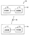
図1は内部に本発明の方法を実現することができる一例としての無線通信システム100を示す。この一例としての無線通信システム100は、ペアのトランシーバ102と104を備え、これらはこれら2つのトランシーバ102、104間に設定された通信チャネル106を介して互いに通信する。チャネル106は、無線通信リンク、例えば、これらに限定されるものではないが、電波(RF)、赤外(IR)、マイクロ波、その他とされる。ただし、代替の通信媒体を採用することもできる。トランシーバ102は、好ましくは、チャネル106から信号を受信するための受信機108と、チャネル106上に信号を送信するための送信機110を備える。同様に、トランシーバ104は受信機114と送信機112を備える。本発明と共に用いるのに適する受信機及び送信機は当業者において周知である。このため、これら受信機及び送信機の詳細な説明はここでは割愛する。
FIG. 1 shows an exemplary
本発明によると、受信ベースバンド信号の信号品質の推定は、無線通信チャネル106を通じての伝送のデータ伝送速度の適合化に有効である。このため、本発明の一面においては、信号劣化(signal degradation、SD)特性が、好ましくは、ある与えられたトランシーバ、例えばトランシーバ102内の、受信機側、例えば受信機108によって決定される。通信チャネル106を通しての信号品質の推定を表すこのSD特性は、典型的には送信機がチャネル106を通じての伝送のデータ伝送速度を設定するために、トランシーバ102内の対応する送信機110に供給される。受信機108は、好ましくは、このSD特性を、入りメッセージ、例えば、データフレーム或いは制御フレーム(例えば、受取確認メッセージ)を処理することで決定する。チャネルを通じての信号のパス能力に悪影響を及ぼすチャネル障害(channel impairments)には、例えば、同一チャネル干渉、遅延信号干渉(delayed signal interference)、(例えば、変調間生成物からの)ナローバンド干渉、熱雑音などが含まれる。トランシーバが、チャネルが準静的対称性の伝送特性(quasi-static symmetric channel transfer characteristics)を有する環境で障害したものと想定した場合は、受取確認メッセージは、本質的に、実際に送信されたそれと同一の信号劣化を受け、このために品質は送信された信号の品質と実質的に同一となる。
According to the present invention, the estimation of the signal quality of the received baseband signal is effective for adapting the data transmission rate of the transmission through the
マルチキャリアシステム、並びに単一キャリアシステムにおいて、各受信フレームは、通常、プレアンブル及び/或いはヘッダ部分を含む。プレアンブルは主として同期の目的で用いられ、ヘッダは、主として、他の目的にも用いられるが、ペイロードデータの長さ及びレートを指定するために用いられる。典型的には、プレアンブルとヘッダは、送信されたデータフレームの同期及び受信を簡単にするために、ペイロードデータと比較して単純かつ頑丈な固定方式にて変調及び符号化される。例えば、IEEE802.11a/g OFDMマルチキャリアシステムにおいては、プレアンブルとヘッダ内のSIGNALフィールドは、バイナリ位相シフトキーイング(binary phase shift keying, BPSK)を用いて変調され、バイナリ畳込み符号(binary convolutional code, BCC)レート1/2符号器を用いて符号化される。SIGNALフィールドは、常に同一のやり方にて変調及び符号化されるために、この情報は、ペイロードデータとは実質的に独立なSD指標を導出するために好都合に用いることができる。SD指標は、本発明によると、例えば、SIGNALフィールドの既知の参照信号布置点(reference constellation points)と受信信号布置点(received constellation points)との間のユークリッド距離(つまり、直線距離)を測定することで決定される。受信信号布置点と参照信号布置点が近いほど、信号品質は良くなり、遠いほど悪くなる。他の距離尺度を用いることもできる。
In multi-carrier systems as well as single carrier systems, each received frame typically includes a preamble and / or a header portion. The preamble is mainly used for synchronization purposes and the header is mainly used for other purposes, but is used to specify the length and rate of payload data. Typically, the preamble and header are modulated and encoded in a simple and robust fixed manner compared to payload data to simplify synchronization and reception of transmitted data frames. For example, in the IEEE802.11a / g OFDM multicarrier system, the preamble and the SIGNAL field in the header are modulated using binary phase shift keying (BPSK), and a binary convolutional code, BCC) Encoded using a
本発明のこの実施例においては、SD指標は、SIGNALフィールドのみの使用では信号品質推定方法の精度に限界があるために、少なくとも2つのファクタに基づいて決定される。つまり、信号品質の推定には、SIGNALフィールドに加えて、例えば、通信チャネル媒体の変動及び/或いは対称性の量や、追加の及び/或いは代替の特性も用いられる。通信チャネルの変動の決定は、高速に変動するチャネルでは、しばしば、信号品質があるパケット内で変化するという点で有益である。同様に、チャネル対称性の決定は、非対称なチャネルでは、送信パケットの信号品質は受信パケットのそれとずれる傾向があるという点で有益である。以下の、本発明の信号品質推定方法の詳細な説明においては、本発明は、一例として、IEEE802.11a/gマルチキャリアシステム内で用いられるものと想定される。更に、説明を簡単にするために、通信チャネルは、ある与えられたパケット期間に渡って、対称かつ一定であるものと想定される。 In this embodiment of the present invention, the SD index is determined based on at least two factors because the use of only the SIGNAL field limits the accuracy of the signal quality estimation method. That is, in addition to the SIGNAL field, for example, the amount of communication channel medium variation and / or symmetry and additional and / or alternative characteristics are used for signal quality estimation. Determining communication channel variations is beneficial in that, for fast-changing channels, signal quality often varies within a packet. Similarly, the determination of channel symmetry is beneficial in that for asymmetric channels, the signal quality of transmitted packets tends to deviate from that of received packets. In the following detailed description of the signal quality estimation method of the present invention, the present invention is assumed to be used in an IEEE 802.11a / g multicarrier system as an example. Further, for simplicity of explanation, the communication channel is assumed to be symmetric and constant over a given packet period.
前述のように、従来のシステムにおいては、システムのデータ速度の適合化は、主としてデータパケットの送信に応答して受信される受取通知メッセージを通じて得られる情報に基づいて行われる。通信チャネルのデータ伝送速度は、通常、正常に送信或いは受信された、或いはエラーの発生した、パケットの数に基づいて変更される。送信側では、受取通知メッセージの受信は、パケットが正常に受信されたものと解釈され、受取通知メッセージが受信されなかった場合は、エラーが発生したものと解釈される。典型的には、所定数のパケットの受信にエラーが発生した場合、伝送速度は、1段階の速度レベルだけ下方に切り替えられ、この過程が有効な受取通知が受信されるまで続けられる。同様に、伝送速度の増加は、典型的には、所定数(例えば、5個)の受取通知が受信された後に行われ、この場合は、送信機は、通常、より高い伝送速度にてパケットを送ることを試みる。送信機は、受取通知が受信された場合は、より高い速度に切り換え、受取通知が受信されない場合は、より低い速度を維持する。 As described above, in conventional systems, the adaptation of the system data rate is mainly based on information obtained through receipt notification messages received in response to the transmission of data packets. The data transmission rate of the communication channel is usually changed based on the number of packets that have been successfully transmitted or received, or in which an error has occurred. On the transmission side, reception of a receipt notification message is interpreted as a packet being received normally, and if a receipt notification message is not received, it is interpreted that an error has occurred. Typically, if an error occurs in the reception of a predetermined number of packets, the transmission rate is switched down by a single level and this process continues until a valid receipt notification is received. Similarly, the increase in transmission rate is typically done after a predetermined number (eg, 5) of receipt notifications have been received, in which case the transmitter will typically send packets at higher transmission rates. Try to send. The transmitter switches to a higher rate if a receipt notification is received and maintains a lower rate if no receipt notification is received.
従来の速度切り替えアプローチを使用した場合、しばしば、送信速度が、特に高密度エリアにおいて必要以上に速く低下される。これは、異なる局間で衝突がより高確率で発生し、このために受取通知メッセージが失われることによる。前述のように、受取通知が失われた場合、送信機は、これを、誤って、エラーが発生したものと解釈し、このために速度切換え手続を不必要に開始する。これを解決するために、本発明は、システムがあるチャネル上の伝送速度をより最適に切換えることができ、従来の速度切換えアプローチより信頼性が高い改善された速度切換え方法を提供する。更に、本発明によると、速度切換えは一度の一段階の増分に制限されず、必要に応じて、速度を選択的により大きな(或いは小さな)増分にて切換えることもできる。 When using a conventional rate switching approach, the transmission rate is often reduced faster than necessary, especially in high density areas. This is due to the fact that collisions between different stations occur with a higher probability and thus the acknowledgment message is lost. As mentioned above, if the receipt notification is lost, the transmitter erroneously interprets this as an error and thus unnecessarily initiates the rate switching procedure. To solve this, the present invention provides an improved rate switching method that allows the system to more optimally switch the transmission rate on a channel and is more reliable than conventional rate switching approaches. Furthermore, according to the present invention, speed switching is not limited to a single step increment, and the speed can be selectively switched in larger (or smaller) increments as needed.
一例としてのIEEE802.11a/gマルチキャリアシステムにおいては、速度の最適化は、送信機内側の媒体アクセス制御(medium access control, MAC)層で行われる。前述のように、本発明の一面によると、SD指標が、好ましくは、受信機側で決定され、ある与えられたトランシーバと関連する対応する送信機に供給される。SD指標は、受信信号(例えば、パケット)に対応する信号品質の尺度を表し、好ましくは、ある与えられた時点にける通信チャネルの状態を推定する。受信機は、信号品質を、例えば、入りメッセージ(ペイロード及び/或いは受取通知データを含む)を処理することで測定する。準静的対称性の伝送特性を有するチャネルを利用するトランシーバが障害したものと想定した場合は、こうして処理されるメッセージは、送信された実際のデータと実質的に同一の劣化を受け、これら2つは、信号品質の観点からは、実質的に同一となる。送信機は、次に、少なくとも一部、このSD指標に基づいて速度切換えの決定を下す。 In the exemplary IEEE 802.11a / g multi-carrier system, speed optimization is performed at the medium access control (MAC) layer inside the transmitter. As mentioned above, according to one aspect of the present invention, the SD indicator is preferably determined at the receiver side and provided to a corresponding transmitter associated with a given transceiver. The SD indicator represents a measure of signal quality corresponding to the received signal (eg, packet) and preferably estimates the state of the communication channel at a given point in time. The receiver measures the signal quality, for example, by processing incoming messages (including payload and / or receipt notification data). Assuming that a transceiver utilizing a channel with quasi-static symmetric transmission characteristics has failed, the messages processed in this way are subject to substantially the same degradation as the actual data transmitted. One is substantially the same from the viewpoint of signal quality. The transmitter then makes a speed switch decision based at least in part on this SD index.
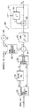
図2Aは、本発明の一面によるSD指標を計算するための方法を実現するための一例としての回路200(例えば、Signal Processing Worksystem, SPWの実現)のブロック図を示す。回路200は、ある与えられたトランシーバの受信機内に実現される。代替として、回路200は、受信機の外部に実現し、例えば、送信機内に組み込むことも、トランシーバ内の別個のセクション、例えば、コントローラ(図示せず)内に実現することもできる。このSD指標決定方法は、好ましくは、変調入力信号に対応する参照信号布置点と受信信号布置点との間のユークリッド距離(つまり、直線距離)を測定する過程を含むが、ただし、代替の測定方法を採用することも考えられる。前述のように、受信信号布置点と参照信号布置点とが近いほど、信号品質は良く、遠いほど悪い。以下では、速度に依存しない処理を達成するため、及び説明を簡単にするために、SD指標の測定には、メッセージのSIGNALフィールドのみが用いられるものと想定される。ただし、本発明から逸脱することなく、信号品質の推定を計算するために、入力信号の追加及び/或いは代替の部分を用いることもできる。上述のIEEE802.11標準に対する拡張である802.11a及び802.11gによると、SIGNALフィールドは24ビットを含み、これらがレート1/2符号化、及びBPSK変調され、このため、当業者においては理解できるように、48個のサンプルが+1或いは−1の位相において検出される。
FIG. 2A shows a block diagram of an example circuit 200 (eg, implementation of Signal Processing Worksystem, SPW) for implementing a method for calculating an SD index according to one aspect of the present invention. The
図面から明らかなように、ブロック202において、ある一つのメッセージのSIGNALフィールドと関連する入力サンプルxが、他の特性も表すが、とりわけ、チャネルの振幅推定と電力減退(power droop)を表す振幅訂正サンプルy(amplitude_cor)によってスケーリングされる(割られる)。ブロック202におけるこのスケーリング過程は、少なくとも部分的に入力サンプルxを対応する参照サンプルに整合されるために遂行される。こうしてスケーリングされたサンプルx/yは、次に、別個のブロック204と206に供給され、ここで、これらは、それぞれ、+1と−1の位相の参照サンプルと比較される。ブロック204と206において遂行される比較には、例えば、こうしてスケーリングされたサンプルを各々(1.0+0j)と(−1.0+0j)の信号と加えることで、各々が同相(I)成分と直交(Q)成分を含むエラーサンプルを生成する過程が含まれる。
As is apparent from the figure, at
その後、それぞれ、ブロック208と210において、位相+1と−1に対応する結果としてのエラーサンプルの大きさが計算される。これら大きさは、好ましくは、当業者において周知のやり方で、二乗されたI及びQ成分の平方根を取ることで決定される。次に、ブロック212において、これら2つのエラー規模信号を比較することで、どちらの信号路がより小さな(最小)エラー規模を有するか決定され、これら2つの信号路の内のより小さなエラー規模値を有する方が、ブロック212の出力として選択される。次に、ブロック214において、より小さな方のエラー規模値が、好ましくは、例えば、配列(アレイ)内に格納される。ブロック214は、パケット内の個々のサンプルに対応する最小エラー規模値を格納及び/或いは配列するための直列/並列変換器或いは代替の手段を備える。ブロック214においてSIGNALフィールドの48個の全ビットが処理された後に、ブロック216において、これら48個の規模値が合計され、結果としての数を用いて信号劣化が表現される。
The resulting error sample sizes corresponding to phases +1 and −1 are then calculated in
図2Bは図2Aに示すSD指標計算回路の代替の実現を示す。このSD指標回路250は、長所として、集積回路(IC)デバイス内により簡単に実現できる。図面から明らかなように、この実現は、除算(通常実現がより困難)は採用せず、2つではなく、1つの信号路のみを有する。第一の簡素化として、全ての入りサンプルが正の半平面にマッピングされる。これは、例えば、ブロック252において、SIGNALフィールドの入りサンプルを実数(Re)成分と虚数(Im)成分に変換し、ブロック254において、実数成分の絶対値を取ることで達成される。この簡素化は、サンプルを負の半平面内で負(−1)の参照点と比較することは、少なくとも大きさの点からは、このサンプルの鏡像バージョン(mirrored version)を正(+1)の参照点と比較することと同一であることから正当化できる。次に、好ましくは、ブロック256において、実数成分の、これも実数成分である絶対値を、虚数成分と結合することで、複素信号が生成される。ブロック256は、実数/虚数成分から複素信号への変換器を用いて実現されるが、これには、当業者において周知のように、例えば、デジタル信号プロセッサ(DSP)が含まれる。
FIG. 2B shows an alternative implementation of the SD index calculation circuit shown in FIG. 2A. As an advantage, the
この代替回路250においては、入りサンプルを+1或いは−1の参照サンプルと比較する代りに、(このやり方では、図2Aの回路におけるようにフロント(前段)におけるスケーリングが必要とされる)、入りサンプルは、ブロック262において、その特定のサブキャリアに対する振幅参照値(amplitude reference)と比較される。ブロック262におけるこの比較は、入りサンプルから振幅参照値を引くことから成る。振幅参照値を表す信号は、ブロック258において、実数成分(Re) amplitude_ refと振幅参照の虚数成分(Im)260とを結合することで形成される。ブロック258は、実数/虚数成分から複素信号への変換器を含み、これは前述のブロック256と同一のやり方にて実現される。処理の複雑さのさらなる低減を、例えば、規模を一次推定値(first order estimation)にて近似したり、或いは代りに電力を計算することで達成することもできる。ブロック262における比較の結果として、IとQ成分から成るエラー信号が得られる。次に、好ましくは、ブロック264において、エラー信号の規模が得られる。エラー信号の規模は、当業者においては周知のやり方にて、エラー信号の二乗されたIとQ成分の平方根を取ることで計算される。
In this
次に、SIGNALフィールド内の個々のサンプルに対応するエラー規模値が積算器(integrator)270によって総和される。積算器270は、各SIGNALフィールドの後にリセットされ、積算器270は、少なくとも一時的に前の規模値を格納する遅延ブロック268に結合される総和ブロック266を含む。積算器270によってSIGNALフィールド内の48ビットに対応する48個の全ての規模値が総和され、結果としての数を用いて信号劣化が表される。
The error magnitude values corresponding to the individual samples in the SIGNAL field are then summed by an
SD指標を決定するためのもう一つの代替の方法においては、SIGNALフィールドサンプルに加えて、パイロットサンプルも処理される。これらパイロットサンプルは、SIGNALフィールドのサンプルと同様に、好ましくは、BPSK変調され、従って、SIGNALフィールドのサンプルと同じやり方にて処理できる。このアプローチでは、長所として、信号劣化は、SIGNALフィールドの48個のサンプルのみではなく、より多くのサンプルを用いて決定され、このために、対応するパケットの信号品質のより正確な推定値を得ることができる。ただし、これらパイロットサンプルは、他の通信システムにおいては様々なシンボルパケットで異なる周波数内に配置されることもあるが、少なくとも一例としての802.11実現においては、実質的に同一の周波数内に配置され、このため、パイロットサンプルのみを採用した場合は、結果としてのSD指標は、特定の周波数と関連する信号劣化のみを推定し、このために周波数選択性フェージングによる悪影響を受ける恐れがある。全ての周波数を用いてSD指標を計算するやり方では周波数選択性フェージングにより強くなるが、少なくともこの理由により、パイロットサンプルのみに基づいてSD指標を決定するやり方は好ましくない。 In another alternative method for determining the SD index, pilot samples are processed in addition to the SIGNAL field samples. These pilot samples, like the SIGNAL field samples, are preferably BPSK modulated and can therefore be processed in the same way as the SIGNAL field samples. This approach has the advantage that the signal degradation is determined using more samples, not just 48 samples in the SIGNAL field, thus obtaining a more accurate estimate of the signal quality of the corresponding packet be able to. However, these pilot samples may be located in different frequencies in different symbol packets in other communication systems, but at least in the 802.11 implementation as an example, they are located in substantially the same frequency, For this reason, when only pilot samples are employed, the resulting SD index only estimates signal degradation associated with a particular frequency, which may be adversely affected by frequency selective fading. Although the method of calculating the SD index using all frequencies is stronger due to frequency selective fading, at least for this reason, the method of determining the SD index based only on pilot samples is not preferable.
次に、単に一例として、図2Aに示す一例としてのSD指標回路200に対するシミュレーション結果を示す。図2Bに示す代替の回路250は幾分異なるシミュレーション値を与えるが、ここでの結論は両方の実施例に概ね同様に適用する。ここで説明される一例としてのシミュレーション結果を得るためには、入り信号は、SIGNALフィールドとデータサンプルを含み、パイロットサンプルは既に除去されているものと想定される。
Next, as an example, a simulation result for the
図3のグラフ300は、本発明による、特定のSNR及びTDSに対して対応する参照/平均SD値を決定するための、参照SD曲線の一例としてのシミュレーション結果を、様々な信号対雑音比(SNR)と時間遅延スプレッド(time delay spread, TDS)値との関係で示す。この一例としてのシミュレーションは、200以上のパケットに対して、様々なSNR値(例えば、6,8,10,12,14,16,18,20,22,24,26,28,30デシベル(dB))とTDS値(例えば、0ns、50ns、及び100ns)に対して遂行された。パケットの数は任意であり、実施にあたっては、サンプルサイズとシミュレーション速度との間の適当な均衡が得られるように選択できることに注意する。
各パケットのSIGNALフィールドが図2Aに示す一例としてのSD指標決定方法に従って処理された。この結果、個々の異なるSNR値に対して200個の異なるSD値が得られた。図3は、3つの異なるTDS値、つまり、それぞれ、0ns、50ns、及び値に対応する、3つの参照SD曲線302、304、及び306を示す。これらTDS値に対応する参照SD曲線が、上述のレンジのSNR値に対してプロットされている。図から明らかなように、約5なるSD値に対しては、曲線302(0nsなるTDS)と曲線306(100nsなるTDS)との間には、SNRにおいて約4dBなる差が存在する。このことは、時間遅延スプレッド(TDS)の影響を受けないシステムでは、実質的に同一のSD値を達成するために、100nsなるTDSを受けるシステムより、約4dB大きなSNRを扱うことができることを意味する。曲線302と曲線306間のSNR値の差は、SD値が低い場合、SD値が高い場合と比較して、少し増加する。理想的には、SIGNALフィールドのSDは、パケット全体のSDと完全に一致するはずである。ただし、これはSIGNALフィールドはパケット全体の一部しか表さないために実際にはそうでない。
The SIGNAL field of each packet was processed according to the exemplary SD index determination method shown in FIG. 2A. This resulted in 200 different SD values for each different SNR value. FIG. 3 shows three reference SD curves 302, 304, and 306 corresponding to three different TDS values, namely 0 ns, 50 ns, and values, respectively. Reference SD curves corresponding to these TDS values are plotted against the SNR values in the above range. As is apparent from the figure, for an SD value of about 5, there is a difference of about 4 dB in SNR between curve 302 (0 ns TDS) and curve 306 (100 ns TDS). This means that a system that is not affected by time delay spread (TDS) can handle a SNR that is about 4 dB larger than a system that receives a TDS of 100 ns to achieve substantially the same SD value. To do. The difference in SNR value between the
単に一例として、図4のグラフ400は、本発明による、SD偏差のシミュレーション結果を、100nsなるTDSと様々のSNRに対して示す。これらシミュレーション結果から、SIGNALフィールドがパケット全体をいかに正確に表すかわかる。この一例としてのシミュレーションは、100個以上の60バイトBPSK変調パケット(各々21個のペイロードシンボルを与える)について遂行された。SIGNALフィールドのシンボルと同様なやり方にて各ペイロードシンボルを処理し、全てのシンボルを平均することで、パケット全体に対するSD値が得られた。これらサンプル内のパケットの全長は以下の通りである:
(21ペイロードシンボル+1SIGNALフィールドシンボル)×48=1056サンプル
パケット毎に静的なチャネルが想定されるために、サンプルの数を増加しても意味のある追加の情報は得られない。
By way of example only, the
(21 payload symbols + 1 SIGNAL field symbol) x 48 = 1056 samples Since a static channel is assumed for each packet, additional meaningful information cannot be obtained even if the number of samples is increased.
これらシミュレーションから、パケット全体のSDと比較してのSIGNALフィールのSDの分布は、概ね正規分布を有することがわかった。当業者においては周知のように、正規分布の確率密度関数(probability density function, PDF)の特性として、そのサンプルの約95%は、μ±2σの区間内に入る。ここで、μは、この分布の、平均として定義され、σは、標準偏差として定義される。平均μは個々のSNRとTDS値に対して零に正規化されるが、ただし、標準偏差σは異なる。特定のSNRとTDS値に対して、あるSD参照値が存在し、これと同一のSNRとTDS値に対して、SIGNALフィールドのSDとパケット全体のSDとの間にある標準偏差σが存在する。平均μは零であるために、標準偏差を直接にSD参照値にマッピングできる。 From these simulations, it was found that the SD distribution of the SIGNAL field compared to the SD of the entire packet has a normal distribution. As is well known to those skilled in the art, approximately 95% of the sample falls within the μ ± 2σ interval as a characteristic of a normally distributed probability density function (PDF). Where μ is defined as the mean of this distribution and σ is defined as the standard deviation. The mean μ is normalized to zero for individual SNR and TDS values, but the standard deviation σ is different. There is an SD reference value for a particular SNR and TDS value, and there is a standard deviation σ between the SD in the SIGNAL field and the SD of the entire packet for the same SNR and TDS value. . Since the mean μ is zero, the standard deviation can be directly mapped to the SD reference value.
図4には、100nsなるTDSと、6dBから30dBの範囲のSNRを用いた一例としてのシミュレーションに対するSD参照値±2σが示される。それぞれ、50nsと100nsのTDSに対する、参照SD曲線402と404も示される。これら曲線402、404は、図3に示される、それぞれ、参照曲線304、306と同一である。ある特定の参照SD値に対する±2σの区間406,408,410,412,414及び416は、SNR軸に対応させることができる。SDの分解能は、この±2σなる区間の間の、SNR値の差として定義される。図から明らかなように、幾つかのSD分布領域は互いに重なり合うが、これは、SDの分解能が、この場合は、4dB SNRより大きなことを意味する。さらに、分解能は、SD値が高いときの方が、SD値が低いときより悪くなることがわかる。例えば、6.81なるSD値におけるSD分解能は約4dB SNRであるのに対して、34なるSD値におけるSD分解能は6dB SNRを超える。
FIG. 4 shows the SD reference value ± 2σ for an example simulation using a TDS of 100 ns and an SNR in the range of 6 dB to 30 dB. Reference SD curves 402 and 404 are also shown for TDS of 50 ns and 100 ns, respectively. These
これらシミュレーション結果からデータ速度切換えの決定を行うために用いることができるさならる情報を、SDをシステム性能(例えば、パケットエラー率(packet error rate, PER))曲線と対応させることで得ることができる。図5は、本発明による、それぞれ、6,9,12,18,24,36,48及び54Mbps(megabits per second)なるデータ速度における、一例としてのシミュレートされたシステム性能曲線a,b,c,d,e,f,g及びhを示す。これら一例としてのシミュレーション結果は、50nsなるTDSを有するフェージングチャネルを用いて、1000バイトのパケットに対して得られたものである。図面から明らかなように、54Mbpsなるデータ速度において5%なる最小PERを達成するためには、SNRは約26.5dBより大きなことを要求される。図3に示されるように、50nsなるTDSに対する26.5dBなるSNRは、約3.4なる参照SD値に対応する。このことは、3.4なるSD値を用いた場合、平均的に、54Mbpsなるデータ速度においてPERは5%となることを示唆する。 From these simulation results, additional information that can be used to determine data rate switching can be obtained by matching SD with system performance (eg, packet error rate, PER) curves. it can. FIG. 5 shows exemplary simulated system performance curves a, b, c at data rates of 6, 9, 12, 18, 24, 36, 48 and 54 Mbps (megabits per second), respectively, according to the present invention. , d, e, f, g and h. These exemplary simulation results were obtained for a 1000 byte packet using a fading channel with a TDS of 50 ns. As is apparent from the figure, to achieve a minimum PER of 5% at a data rate of 54 Mbps, the SNR is required to be greater than about 26.5 dB. As shown in FIG. 3, an SNR of 26.5 dB for a TDS of 50 ns corresponds to a reference SD value of about 3.4. This suggests that, on average, when using an SD value of 3.4, the PER is 5% at a data rate of 54 Mbps.
上述のように、3.4なるSD値を用いた場合、54Mbpsなるデータ速度において、PERは5%となるものと想定する。これら一例としてのシミュレーション結果によると、このことは、3.4或いはそれ以下の測定SD値を用いることで、その特定のデータ速度に対して、少なくとも5%なるPERを十分に達成できることを意味する。ただし、前述のように、測定SD値は、パケット全体のSDと異なるために、所定の安全マージン(safety margin)を採用することが推奨される。 As described above, when an SD value of 3.4 is used, PER is assumed to be 5% at a data rate of 54 Mbps. According to these exemplary simulation results, this means that using a measured SD value of 3.4 or less can sufficiently achieve a PER of at least 5% for that particular data rate. However, as described above, since the measured SD value is different from the SD of the whole packet, it is recommended to adopt a predetermined safety margin.
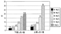
図4との関連で、これら一例としてのシミュレーション結果を用いてSIGNALフィールドのSDとパケット全体のSDとの間の偏差を測定し、これから分解能帯域幅(resolution bandwidth)を決定することができる。これら一例としてのシミュレーションから、TDS値が高いほど分解能は悪くなることがわかる。こうして、100nsなるTDSにおけるSDに対する分解能の結果を、より低いTDSにおけるSD参照曲線の分解能に対する最悪の場合のシナリオ(worst case scenario)とみなすことができる。ある特定のデータ速度に対して5%なるPERを与えるSNRに、分解能帯域幅の半分を加えることで、最大でも、5%なるPERを、97.5%なる確かで与えるSD値が得られる。また、これから分解能帯域幅の半分を引くことで、最小でも、5%なるPERを、97.5%なる確かで与えるSD値が得られる。こうして、このようにして導かれた2つのSD値を、この特定のデータ速度に対する、それぞれ、上限閾値レベル及び下限閾値レベルとみなすことができる。以下のテーブルの列4と5は、対応するデータ速度に対する、それぞれ、一例としての上限及び下限閾値の値を示す。これら結果は、図6にもグラフ的に示される。
In the context of FIG. 4, these example simulation results can be used to measure the deviation between the SD in the SIGNAL field and the SD of the entire packet, from which the resolution bandwidth can be determined. From these example simulations, it can be seen that the higher the TDS value, the worse the resolution. Thus, the resolution results for SD at a TDS of 100 ns can be viewed as a worst case scenario for the resolution of the SD reference curve at a lower TDS. By adding half of the resolution bandwidth to an SNR that gives a PER of 5% for a particular data rate, an SD value that gives a PER of 5% at a maximum of 97.5% is obtained at most. Also, by subtracting half of the resolution bandwidth from this, an SD value that gives a PER of 5% with a certainty of 97.5% is obtained at a minimum. Thus, the two SD values thus derived can be considered as the upper threshold level and the lower threshold level, respectively, for this particular data rate.

図7は、本発明の一面に従って構成される一例としての速度切換え方法700の状態図である。この一例としての速度切換え方法700は、上述のようにして決定されるSD指標を採用する。図面に示すように、この一例としての速度切換え方法は、好ましくは、3つの状態、つまり、「現在の速度(Current Rate)」なる状態702、「より高い速度(Higher Rate)」なる状態704、及び「より低い速度(Lower Rate)」なる状態706を含む。ただし、追加の或いは代替の状態を用いることもできる。ここでは、この方法は、状態702から開始されるものと想定される。状態702において、現在のデータ速度は同一にとどまり、下限閾値レベルL_Th及び上限閾値レベルU_Thは、現在のデータ速度に対する各々の閾値レベルに設定される。
FIG. 7 is a state diagram of an exemplary
SD指標によって提供される測定SD値が、現在の下限閾値以上であり、かつ、現在の上限閾値以下である場合は、この一例としての方法700は、状態702にとどまり、こうしてデータ伝送速度は変えられない。測定SD値がより高いデータ速度に対応する下限閾値レベルより低い場合は、速度の上方への切換え(rate up-switching)が遂行される。こうして、本発明の一面によると、速度の上方への切換えは、現在のSD値を一つ或いは複数のより高いデータ速度に対応する複数の下限閾値と比較することで遂行される。現在のSD値がこれら複数のより高いデータ速度に対応するこれら複数の下限閾値の一つより低い場合は、現在のデータ速度はこの基準を満たす最も高いデータ速度に切換えられる。このやり方では、長所として、データ速度を、1段階以上、増加させることが可能となる。この例においては、方法700は、次に、状態704に入る。状態704において、好ましくは、現在のデータ速度は、より高いデータ速度にセットされ、上限閾値レベルがこのより高いデータ速度に対応する閾値レベルに設定される。このより高いデータ速度が本質的に現在のデータ速度となるために、この方法は、上述の修正を完了した後に、再び状態702に入る。
If the measured SD value provided by the SD indicator is greater than or equal to the current lower threshold and less than or equal to the current upper threshold, the
速度の下方への切換え(rate down-switching)は、従来と同様にエラーの発生に基づいて行うこともできるが、ただし、好ましくは、速度の下方への切換えは、過去に測定されたSD情報にも基づいても行われる。例えば、この方法は、所定の数(例えば、2個)のエラーが連続して検出され、かつ、所定の数の過去に測定されたSD値が現在のデータ速度に対応する上限閾値レベルより高いときは、主判定路708を経て状態706に入る。状態706において、現在のデータ速度がより低いデータ速度に設定され、上限閾値がこのより低いデータ速度に対応する閾値レベルに設定される。速度の上方への切換えの場合と同様に、このより低いデータ速度が本質的に現在のデータ速度となるために、この方法700は、再び状態702に入る。本発明の一面によると、速度の下方への切換えは、上述の速度の上方へのを切換え方法と同様に、データ速度を一度に1段階以上低減することもできる。
The rate down-switching can be performed based on the occurrence of an error as in the prior art, but preferably the rate down-switching is performed in the past when the SD information measured in the past is used. Also based on. For example, this method detects a predetermined number (eg, 2) of errors continuously, and the predetermined number of past measured SD values is higher than the upper threshold level corresponding to the current data rate. When the
この一例としての方法700は、急速なSD変化は発生しないことを想定する。従って、所定の数のエラーが検出され、さもなければより低いデータ伝送速度への切換えが必要とされるが、ただし、過去に測定されたSD値が現在のデータ速度に対する上限閾値レベルより低い場合は、この方法は、現在のデータ速度を変更しないままに保つことを選択する。このような状況においては、検出されたエラーは、チャネル状態の劣化によるのではなく、衝突に起因するものとして扱われる。
This
比較的多数の連続するエラーが検出される(従ってシステムのスループットが低減される)が、ただし、過去の測定されたSD値は現在のデータ速度に対応する上限閾値レベルより低いという、潜在的デッドロック状態を回避するために、この方法は、状態702から状態706への副判定路710を含む。この副経路710においては、速度を下方に切換える決定は、検出された連続するエラーの数のみに基づいて行われ、過去に測定されたSD値は考慮から外される。例えば、予め設定された数(例えば、5個)の連続するエラーが発生した場合、この方法は、自動的に状態706に入り、過去のSD値をチェックすることなく、データ速度を低減する。このために副判定路710に対して検出されるべき連続するエラーの数は、好ましくは、主判定路708に対して検出されるべきエラーの数より高く設定される。
Ru is detected errors relatively large number of consecutive (and thus throughput of the system is reduced) is, however, that the past measured SD value lower than the upper threshold level corresponding to the current data rate, potentially dead In order to avoid a lock condition, the method includes a
測定SD値を複数のパケットに渡って平均化するようなシミュレーションを遂行することもできる。この場合は、上限と下限閾値レベルが互いにより接近し、異なるデータ速度間の弁別は容易になるが、ただし、切換え速度は遅くなる。更に、複数のパケットに渡って平均化する場合は、一連のパケット間の時間長を考慮に入れることが重要となる。パケット間の時間が大きな場合は、チャネル状態が大きく変化し、このためにSD値が実際のチャネル状態を正確には推定しなくなる恐れもある。 It is also possible to perform a simulation in which the measured SD value is averaged over a plurality of packets. In this case, the upper and lower threshold levels are closer to each other and discrimination between different data rates is facilitated, but the switching speed is slower. Furthermore, when averaging over a plurality of packets, it is important to take into account the time length between a series of packets. If the time between packets is large, the channel condition can change significantly, which can cause the SD value to not accurately estimate the actual channel condition.
上述の一例としてのシミュレーションより、速度を切換えるための決定を測定されたSD値に基づいて行うことができることがわかる。本発明のもう一つの実現として、SDの分解能の定義を甘くし、上限及び下限閾値レベルを緩和することも考えられる。ただし、このやり方では、5%PERなる特定の基準に対する速度推定の信頼性は落ちる。閾値レベルを緩和するためのもう一つのアプローチとして、より緩いPER閾値、例えば、5%PERではなく、10%PERを採用することもできる。 From the example simulation described above, it can be seen that the decision to switch speed can be made based on the measured SD value. As another realization of the present invention, it may be possible to relax the definition of SD resolution and relax the upper and lower threshold levels. However, this approach reduces the reliability of speed estimation for a specific criterion of 5% PER. Another approach to mitigating the threshold level is to employ a more relaxed PER threshold, eg, 10% PER instead of 5% PER.
本発明のもう一面によると、トランシーバのデータ伝送速度を制御するための回路は、ここに開示される本発明による方法の少なくとも一部を遂行するように構成可能なコントローラ(図示せず)を備える。ここで用いられる「コントローラ」なる語句は、あらゆる処理デバイスを含むことを意図され、これには、例えば、中央処理ユニット(CPU)及び/或いは他の処理回路(例えば、マイクロプロセッサ)を含む処理デバイスも含まれる。加えて、「コントローラ」なる語句は、複数のコントローラデバイスが用いられ、ある一つのコントローラデバイスと関連する様々な要素が他の複数のコントローラデバイスによって共有されるような状況も指す。 According to another aspect of the invention, a circuit for controlling the data transmission rate of a transceiver comprises a controller (not shown) configurable to perform at least part of the method according to the invention disclosed herein. . The term “controller” as used herein is intended to include any processing device, including, for example, a central processing unit (CPU) and / or other processing circuitry (eg, a microprocessor). Is also included. In addition, the phrase “controller” also refers to situations where multiple controller devices are used and various elements associated with one controller device are shared by multiple other controller devices.
本発明の幾つかの実施例が付属の図面との関連で説明されたが、本発明はこれら特定の実施例に制限されるものではなく、様々な他の変更及び修正が、クレームの範囲から逸脱することなく可能である。例えば、本発明は、IEEE 802.11標準以外の他の標準(例えば、IEEE 802.15)並びに非標準のアプリケーションとともに用いることもできる。 While several embodiments of the present invention have been described in connection with the accompanying drawings, the present invention is not limited to these specific embodiments, and various other changes and modifications can be made from the scope of the claims. It is possible without departing. For example, the present invention can be used with other standards other than the IEEE 802.11 standard (eg, IEEE 802.15) as well as non-standard applications.
100 無線通信システム
102 トランシーバ
104 トランシーバ
106 通信チャネル
108 受信機
110 送信機
112 送信機
114 受信機
250 SD指標回路
266 総和ブロック
268 遅延ブロック
270 積算器
100 wireless communication system
102 transceiver
104 transceiver
106 communication channels
108 Receiver
110 Transmitter
112 Transmitter
114 receiver
250 SD index circuit
266 Sum block
268 delay block
270 integrator
Claims (8)
該受信機の所で受信される信号に対応する信号品質特性であって、該無線通信チャネルを通して信号劣化の推定を表す信号品質特性を、一つ或いは複数の参照信号布置点と一つ或いは複数の受信信号布置点との間の差を測定することにより決定するステップと、
該送信機のデータ伝送速度を、少なくとも一部、該信号品質特性に基づいて修正するステップと、
該測定された差の少なくとも一部を、該受信信号の複数のデータサンプルと制御サンプルの一方の、複数のサンプルに渡って平均化するステップであって、該信号品質特性がこの結果として得られる平均された差の関数として表現されるステップとを含み、
該信号品質特性を決定するステップが、該一つ或いは複数の受信信号布置点と該一つ或いは複数の対応する参照信号布置点とを整合するステップによって、該一つ或いは複数の参照信号布置点と一つ或いは複数の受信信号布置点との間の差を、該受信信号に対応する複数のデータサンプルと複数の制御サンプルの少なくとも一方に対して測定するステップを含み、
該整合するステップは規定されたスケーリング要素によって該一つ或いは複数の受信信号布置点をスケーリングするステップを含み、
該複数の測定された差の少なくとも一部を平均化するステップが、該受信信号の現在のデータサンプルに対応する差値と該受信信号の前のデータサンプルに対応する差値とを加えるステップを含む方法。 A method for controlling a data transmission rate of at least one transceiver for use in a wireless system comprising at least one transceiver, comprising a transmitter and a receiver, and configured to communicate over a wireless communication channel. ,
A signal quality characteristic corresponding to a signal received at the receiver, the signal quality characteristic representing an estimate of signal degradation through the wireless communication channel, one or more reference signal placement points and one or more reference signal placement points. Determining by measuring the difference between the received signal placement point of
Modifying the data transmission rate of the transmitter based at least in part on the signal quality characteristics;
Averaging at least a portion of the measured difference over a plurality of samples, one of a plurality of data samples and a control sample of the received signal, wherein the signal quality characteristic is obtained as a result A step expressed as a function of the averaged difference,
The step of determining the signal quality characteristic comprises the step of aligning the one or more received signal placement points with the one or more corresponding reference signal placement points, so that the one or more reference signal placement points. Measuring at least one of a plurality of data samples and a plurality of control samples corresponding to the received signal,
The matching step includes scaling the one or more received signal placement points by a defined scaling factor;
Averaging at least a portion of the plurality of measured differences adds a difference value corresponding to a current data sample of the received signal and a difference value corresponding to a previous data sample of the received signal; Including methods.
該受信信号に対応する複数のデータサンプルの少なくとも一部の各々に対して、該受信信号布置点と該対応する参照信号布置点との間の差の関数として表現されるエラー信号を生成するステップと、
該測定された差を表すエラー信号の大きさを決定するステップと、を含む請求項1記載の方法。 Measuring the difference comprises:
Generating, for each of at least some of the plurality of data samples corresponding to the received signal, an error signal expressed as a function of a difference between the received signal placement point and the corresponding reference signal placement point. When,
The method of claim 1, comprising determining a magnitude of an error signal representative of the measured difference.
該受信信号を少なくとも実数成分と虚数成分とに変換するステップと、
該受信信号の該虚数成分と該実数成分の絶対値とを結合することで複素信号を生成するステップと、
該複素信号と該受信信号の対応するサブキャリアに対する振幅参照信号との間の差を測定するステップと、
該複素信号と振幅参照信号との間の差の大きさを決定するステップであって、この大きさが該一つ或いは複数の参照信号布置点と一つ或いは複数の受信信号布置点との間の測定された差を表すものであるステップとを含む請求項1記載の方法。 Measuring a difference between one or more reference signal placement points and one or more received signal placement points;
Converting the received signal into at least a real component and an imaginary component;
Generating a complex signal by combining the imaginary component of the received signal and the absolute value of the real component;
Measuring a difference between the complex signal and an amplitude reference signal for a corresponding subcarrier of the received signal;
Determining a magnitude of a difference between the complex signal and the amplitude reference signal, the magnitude being between the one or more reference signal placement points and one or more received signal placement points. The method of claim 1 comprising the step of representing a measured difference of.
該複数のデータサンプルの少なくとも一部の各々に対して、少なくとも該データサンプルの第一の位相に対応する第一の差或いは該データサンプルの第二の位相に対応する第二の差の一方に対応する、最小エラー規模を決定するステップと、
該最小エラー規模の少なくとも一部を格納するステップと、
該格納された最小エラー規模を総和するステップと、を含む請求項1記載の方法。 Averaging at least a portion of the plurality of measured differences comprises:
For each of at least some of the plurality of data samples, at least one of a first difference corresponding to a first phase of the data sample or a second difference corresponding to a second phase of the data sample. Determining a corresponding minimum error magnitude;
Storing at least a portion of the minimum error magnitude;
2. The method of claim 1, comprising summing the stored minimum error magnitudes.
そのデータ伝送速度に対応する、それぞれ、参照最小信号品質特性及び参照最大信号品質特性を表す、下限及び上限閾値レベルを決定するステップと、
該受信信号の信号品質特性を測定するステップと、
該測定された信号品質特性が該下限と上限閾値レベルの範囲内にあるか否か決定するステップと、
該測定された信号品質特性が該下限及び上限閾値レベルの範囲内にある場合は、データ伝送速度を維持するステップと、
該測定された信号品質特性が一つ或いは複数のより高いデータ速度に対応する一つ或いは複数の下限閾値レベルより低い場合は、データ伝送速度を増加するステップと、を含む請求項1記載の方法。 Modifying the data transmission rate of the transmitter;
Determining a lower and upper threshold level representing a reference minimum signal quality characteristic and a reference maximum signal quality characteristic, respectively, corresponding to the data transmission rate;
Measuring signal quality characteristics of the received signal;
Determining whether the measured signal quality characteristic is within the lower and upper threshold levels;
Maintaining the data transmission rate if the measured signal quality characteristic is within the lower and upper threshold levels;
2. The method of claim 1, comprising increasing the data transmission rate if the measured signal quality characteristic is lower than one or more lower threshold levels corresponding to one or more higher data rates. .
一つ或いは複数のデータ伝送速度に対応する、それぞれ、参照最小信号品質特性及び参照最大信号品質特性を表す、複数の下限及び上限閾値レベルを決定するステップと、
前の受信信号サンプルに対応する少なくとも一つの測定信号品質特性を格納するステップと、
該少なくとも一つのトランシーバと関連する連続して発生するエラーの数を検出するステップと、
該測定信号品質特性が該下限及び上限閾値レベルの範囲内にある場合は、データ伝送速度を維持するステップと、
該少なくとも一つの格納された測定信号品質特性が該複数の上限閾値レベルの少なくとも1つより大きく、かつ、該検出エラーの数が第一の数より大きな場合は、データ伝送速度を低減するステップと、を含む請求項1記載の方法。 Modifying the data transmission rate comprises:
Determining a plurality of lower and upper threshold levels respectively representing a reference minimum signal quality characteristic and a reference maximum signal quality characteristic corresponding to one or more data transmission rates;
Storing at least one measured signal quality characteristic corresponding to a previous received signal sample;
Detecting a number of consecutive errors associated with the at least one transceiver;
Maintaining the data transmission rate if the measured signal quality characteristic is within the lower and upper threshold levels;
Reducing the data transmission rate if the at least one stored measurement signal quality characteristic is greater than at least one of the plurality of upper threshold levels and the number of detection errors is greater than a first number; The method of claim 1 comprising:
少なくとも一つのコントローラを備え、該少なくとも一つのコントローラが、
(1)該受信機の所で受信される信号に対応する信号品質特性であって、該無線通信チャネルを通じての信号劣化の推定を表す信号品質特性を、一つ或いは複数の参照信号布置点と一つ或いは複数の受信信号布置点との間の差を測定することで決定し、および
(2)該送信機のデータ伝送速度を、少なくとも一部、該信号品質特性に基づいて修正できるよう動作し、
該信号品質特性の決定において、該少なくとも一つのコントローラが、該一つ或いは複数の受信信号布置点と該一つ或いは複数の対応する参照信号布置点とを整合することによって、該一つ或いは複数の参照信号布置点と一つ或いは複数の受信信号布置点との間の差を、該受信信号に対応する複数のデータサンプルと複数の制御サンプルの少なくとも一方に対して測定するよう動作し、
該整合において、規定されたスケーリング要素によって該一つ或いは複数の受信信号布置点をスケーリングし、
該少なくとも一つのコントローラが、該測定された差の少なくとも一部を、該受信信号の複数のデータサンプルと制御サンプルの一方の、複数のサンプルに渡って平均化するよう動作し、該信号品質特性がこの結果として得られる平均された差の関数として表現され、該複数の測定された差の少なくとも一部を平均化することが、該受信信号の現在のデータサンプルに対応する差値と該受信信号の前のデータサンプルに対応する差値とを加えることを含み、
該少なくとも一つのコントローラが、
(3)該データ伝送速度に対応する、それぞれ、参照最小信号品質特性及び参照最大信号品質特性を表す、複数の下限及び上限閾値レベルを決定し、
(4)該受信信号の信号品質特性を測定し、
(5)該測定信号品質特性が該下限及び上限閾値レベルの範囲内にあるかどうかを決定し、
(6)該測定信号品質特性が該下限及び上限閾値レベルの範囲内にある場合は、データ伝送速度を維持し、
(7)該測定信号品質特性が、1つ或いは複数の対応する上限データ速度に関連する1つ或いは複数の下限閾値レベルより小さい場合は、データ伝送速度を増加するよう動作する回路。 A circuit for selectively adapting a data transmission rate of a wireless system including a transmitter and a receiver and comprising a transceiver configurable for communicating over a wireless communication channel, comprising:
Comprising at least one controller, the at least one controller comprising:
(1) A signal quality characteristic corresponding to a signal received at the receiver, the signal quality characteristic representing an estimate of signal degradation through the wireless communication channel, and one or more reference signal placement points; Determining by measuring a difference between one or a plurality of received signal placement points, and (2) operating so that the data transmission rate of the transmitter can be modified based at least in part on the signal quality characteristics And
In determining the signal quality characteristic, the at least one controller aligns the one or more received signal placement points with the one or more corresponding reference signal placement points, thereby providing the one or more reference signal placement points. The difference between the reference signal placement point and one or more received signal placement points is measured for at least one of a plurality of data samples and a plurality of control samples corresponding to the received signal,
In the alignment, scaling the one or more received signals constellation points by a defined scaling element,
The at least one controller is operable to average at least a portion of the measured difference over a plurality of samples, one of a plurality of data samples and a control sample of the received signal, and the signal quality characteristic; Is expressed as a function of the resulting averaged difference, and averaging at least a portion of the plurality of measured differences results in a difference value corresponding to a current data sample of the received signal and the received Adding difference values corresponding to previous data samples of the signal,
The at least one controller comprises:
(3) determining a plurality of lower and upper threshold levels respectively representing a reference minimum signal quality characteristic and a reference maximum signal quality characteristic corresponding to the data transmission rate;
(4) measuring the signal quality characteristics of the received signal;
(5) determine whether the measured signal quality characteristic is within the lower and upper threshold levels;
(6) If the measured signal quality characteristic is within the lower and upper threshold levels, maintain the data transmission rate;
(7) A circuit that operates to increase the data transmission rate if the measured signal quality characteristic is less than one or more lower threshold levels associated with one or more corresponding upper data rates.
少なくとも一つのコントローラを備え、該少なくとも一つのコントローラが、
(1)該受信機の所で受信される信号に対応する信号品質特性であって、該無線通信チャネルを通じての信号劣化の推定を表す信号品質特性を、一つ或いは複数の参照信号布置点と一つ或いは複数の受信信号布置点との間の差を測定することで決定し、および
(2)該送信機のデータ伝送速度を、少なくとも一部、該信号品質特性に基づいて修正するよう動作し、
該信号品質特性の決定において、該少なくとも一つのコントローラが、該一つ或いは複数の受信信号布置点と該一つ或いは複数の対応する参照信号布置点とを整合することによって、該一つ或いは複数の参照信号布置点と一つ或いは複数の受信信号布置点との間の差を、該受信信号に対応する複数のデータサンプルと複数の制御サンプルの少なくとも一方に対して測定するよう動作し、
該整合において、規定されたスケーリング要素によって該一つ或いは複数の受信信号布置点をスケーリングし、
該少なくとも一つのコントローラが、該測定された差の少なくとも一部を、該受信信号の複数のデータサンプルと制御サンプルの一方の、複数のサンプルに渡って平均化するよう動作し、該信号品質特性がこの結果として得られる平均された差の関数として表現され、該複数の測定された差の少なくとも一部を平均化することが、該受信信号の現在のデータサンプルに対応する差値と該受信信号の前のデータサンプルに対応する差値とを加えることを含み、
該少なくとも一つのコントローラが、
(3)該データ伝送速度に対応する、それぞれ、参照最小信号品質特性及び参照最大信号品質特性を表す、複数の下限及び上限閾値レベルを決定し、
(4)該受信信号の信号品質特性を測定し、
(5)該測定信号品質特性が該下限及び上限閾値レベルの範囲内にあるかどうかを決定し、
(6)該測定信号品質特性が該下限及び上限閾値レベルの範囲内にある場合は、データ伝送速度を維持し、
(7)該測定信号品質特性が、1つ或いは複数の対応する上限データ速度に関連する1つ或いは複数の下限閾値レベルより小さい場合は、データ伝送速度を増加するよう動作する集積回路。 An integrated circuit comprising at least one circuit for selectively adapting a data transmission rate of a wireless system comprising a transmitter and a receiver and comprising a transceiver configurable for communicating over a wireless communication channel, comprising: At least one circuit
Comprising at least one controller, the at least one controller comprising:
(1) A signal quality characteristic corresponding to a signal received at the receiver, the signal quality characteristic representing an estimate of signal degradation through the wireless communication channel, and one or more reference signal placement points; Determining by measuring a difference between one or more received signal placement points, and (2) operating to modify the data transmission rate of the transmitter based at least in part on the signal quality characteristics And
In determining the signal quality characteristic, the at least one controller aligns the one or more received signal placement points with the one or more corresponding reference signal placement points, thereby providing the one or more reference signal placement points. The difference between the reference signal placement point and one or more received signal placement points is measured for at least one of a plurality of data samples and a plurality of control samples corresponding to the received signal,
In the alignment, scaling the one or more received signals constellation points by a defined scaling element,
The at least one controller is operable to average at least a portion of the measured difference over a plurality of samples, one of a plurality of data samples and a control sample of the received signal, and the signal quality characteristic; Is expressed as a function of the resulting averaged difference, and averaging at least a portion of the plurality of measured differences results in a difference value corresponding to a current data sample of the received signal and the received Adding difference values corresponding to previous data samples of the signal,
The at least one controller comprises:
(3) determining a plurality of lower and upper threshold levels respectively representing a reference minimum signal quality characteristic and a reference maximum signal quality characteristic corresponding to the data transmission rate;
(4) measuring the signal quality characteristics of the received signal;
(5) determine whether the measured signal quality characteristic is within the lower and upper threshold levels;
(6) If the measured signal quality characteristic is within the lower and upper threshold levels, maintain the data transmission rate;
(7) An integrated circuit that operates to increase the data transmission rate if the measured signal quality characteristic is less than one or more lower threshold levels associated with one or more corresponding upper data rates.
Applications Claiming Priority (2)
| Application Number | Priority Date | Filing Date | Title |
|---|---|---|---|
| US10/305554 | 2002-11-27 | ||
| US10/305,554 US7499486B2 (en) | 2002-11-27 | 2002-11-27 | Data transmission rate adaptation in a wireless communication system |
Publications (3)
| Publication Number | Publication Date |
|---|---|
| JP2004180319A JP2004180319A (en) | 2004-06-24 |
| JP2004180319A5 JP2004180319A5 (en) | 2006-10-05 |
| JP4982029B2 true JP4982029B2 (en) | 2012-07-25 |
Family
ID=32298055
Family Applications (1)
| Application Number | Title | Priority Date | Filing Date |
|---|---|---|---|
| JP2003396445A Expired - Fee Related JP4982029B2 (en) | 2002-11-27 | 2003-11-27 | Adapting data transmission rates in wireless communication systems |
Country Status (4)
| Country | Link |
|---|---|
| US (2) | US7499486B2 (en) |
| EP (1) | EP1424802B1 (en) |
| JP (1) | JP4982029B2 (en) |
| DE (1) | DE60311224T2 (en) |
Families Citing this family (44)
| Publication number | Priority date | Publication date | Assignee | Title |
|---|---|---|---|---|
| US7499486B2 (en) | 2002-11-27 | 2009-03-03 | Agere Systems Inc. | Data transmission rate adaptation in a wireless communication system |
| US20040160922A1 (en) | 2003-02-18 | 2004-08-19 | Sanjiv Nanda | Method and apparatus for controlling data rate of a reverse link in a communication system |
| US7660282B2 (en) | 2003-02-18 | 2010-02-09 | Qualcomm Incorporated | Congestion control in a wireless data network |
| US8150407B2 (en) * | 2003-02-18 | 2012-04-03 | Qualcomm Incorporated | System and method for scheduling transmissions in a wireless communication system |
| US8081598B2 (en) * | 2003-02-18 | 2011-12-20 | Qualcomm Incorporated | Outer-loop power control for wireless communication systems |
| US7155236B2 (en) | 2003-02-18 | 2006-12-26 | Qualcomm Incorporated | Scheduled and autonomous transmission and acknowledgement |
| US8023950B2 (en) | 2003-02-18 | 2011-09-20 | Qualcomm Incorporated | Systems and methods for using selectable frame durations in a wireless communication system |
| US8391249B2 (en) | 2003-02-18 | 2013-03-05 | Qualcomm Incorporated | Code division multiplexing commands on a code division multiplexed channel |
| TWI250741B (en) * | 2003-02-26 | 2006-03-01 | Realtek Semiconductor Corp | Method for automatically and dynamically adjusting packet transmission speed of wireless communication network system |
| US7215930B2 (en) | 2003-03-06 | 2007-05-08 | Qualcomm, Incorporated | Method and apparatus for providing uplink signal-to-noise ratio (SNR) estimation in a wireless communication |
| US8705588B2 (en) | 2003-03-06 | 2014-04-22 | Qualcomm Incorporated | Systems and methods for using code space in spread-spectrum communications |
| US7593488B2 (en) * | 2003-04-25 | 2009-09-22 | Harris Corporation | Method and apparatus for detection of signal without the aid of training sequence |
| US8477592B2 (en) | 2003-05-14 | 2013-07-02 | Qualcomm Incorporated | Interference and noise estimation in an OFDM system |
| US8234399B2 (en) * | 2003-05-29 | 2012-07-31 | Seagate Technology Llc | Method and apparatus for automatic phy calibration based on negotiated link speed |
| TW200507471A (en) * | 2003-06-25 | 2005-02-16 | Koninkl Philips Electronics Nv | Distortion/efficiency adaptation in a variable data-rate radio transmitter |
| JP4008861B2 (en) * | 2003-07-15 | 2007-11-14 | 富士通株式会社 | Wireless data transmission system |
| US8489949B2 (en) * | 2003-08-05 | 2013-07-16 | Qualcomm Incorporated | Combining grant, acknowledgement, and rate control commands |
| KR100541526B1 (en) | 2004-01-30 | 2006-01-10 | 에스케이 텔레콤주식회사 | Methods and apparatus for multimedia data transmission quality measurement |
| US8498215B2 (en) * | 2004-11-16 | 2013-07-30 | Qualcomm Incorporated | Open-loop rate control for a TDD communication system |
| US20060146709A1 (en) * | 2004-12-30 | 2006-07-06 | Boris Ginzburg | Device, system and method for limiting data rates supported by a wireless LAN |
| ES2420987T3 (en) * | 2005-04-29 | 2013-08-28 | Sony Deutschland Gmbh | Transmission device, reception device and communication method for an OFDM communications system with new preamble structure |
| US8144814B2 (en) * | 2006-05-22 | 2012-03-27 | Qualcomm Incorporated | Signal quality estimator |
| JP4167702B2 (en) * | 2006-06-21 | 2008-10-22 | Necアクセステクニカ株式会社 | Wireless LAN system, communication apparatus, and automatic optimization method for compression processing |
| US8320244B2 (en) * | 2006-06-30 | 2012-11-27 | Qualcomm Incorporated | Reservation based MAC protocol |
| JP4805081B2 (en) * | 2006-09-29 | 2011-11-02 | 富士通株式会社 | Wireless relay device, wireless relay method, and wireless relay program |
| GB0622830D0 (en) * | 2006-11-15 | 2006-12-27 | Cambridge Silicon Radio Ltd | Transmission rate selection |
| GB0622829D0 (en) | 2006-11-15 | 2006-12-27 | Cambridge Silicon Radio Ltd | Transmission rate selection |
| US8493955B2 (en) * | 2007-01-05 | 2013-07-23 | Qualcomm Incorporated | Interference mitigation mechanism to enable spatial reuse in UWB networks |
| US8295189B2 (en) * | 2007-05-11 | 2012-10-23 | Microsoft Corporation | Interference detection |
| US9112645B2 (en) * | 2007-05-11 | 2015-08-18 | Microsoft Technology Licensing, Llc | Channel control based on error correction values |
| US7872974B2 (en) * | 2007-09-27 | 2011-01-18 | Freescale Semiconductor Inc. | System and method for handling or avoiding disruptions in wireless communication |
| US8036240B2 (en) * | 2007-12-14 | 2011-10-11 | Microsoft Corporation | Software defined cognitive radio |
| US8619620B2 (en) * | 2008-09-16 | 2013-12-31 | Qualcomm Incorporated | Methods and systems for transmission mode selection in a multi channel communication system |
| KR101196258B1 (en) * | 2008-11-19 | 2012-11-05 | 한국전자통신연구원 | Apparatus and method for providing broadcasting service and system thereof |
| KR101218401B1 (en) * | 2008-12-04 | 2013-01-18 | 한국전자통신연구원 | Method and apparatus for transmitting and receiving packet capable of detecting system of data |
| JP5559420B2 (en) | 2010-04-12 | 2014-07-23 | クゥアルコム・インコーポレイテッド | Delimiter detection for low overhead communication in networks |
| CN101873185B (en) * | 2010-06-24 | 2014-11-05 | 惠州Tcl移动通信有限公司 | Sensitivity testing method, device and detection equipment of GSM (Global System for Mobile Communications) communication terminal |
| CN102340345B (en) * | 2010-07-14 | 2016-02-10 | 中兴通讯股份有限公司 | A kind of method of measuring quality of phase modulation signals of light and device |
| US9203576B2 (en) * | 2012-08-03 | 2015-12-01 | Telefonaktiebolaget L M Ericsson (Publ) | Quasi co-located antenna ports for channel estimation |
| US8918136B2 (en) * | 2012-11-29 | 2014-12-23 | At&T Mobility Ii Llc | Adjustment of transmit power parameter |
| US20160135083A1 (en) * | 2014-11-07 | 2016-05-12 | Newracom, Inc. | Method and apparatus for transmitting frames |
| CN105491596B (en) * | 2015-11-26 | 2019-07-09 | 惠州Tcl移动通信有限公司 | Acquisition methods, system and mobile terminal are tested in a kind of mobile terminal sensitivity automatically |
| RU175190U1 (en) * | 2017-04-13 | 2017-11-27 | Публичное акционерное общество "Российский институт мощного радиостроения" | DEVICE FOR ASSESSING THE PROBABILITY OF ERROR BY BIT FOR SIGNALS WITH SIXTEEN POSITION PHASE MODULATION BY TWO POSITION SIGNALS |
| CN114448556B (en) * | 2020-11-05 | 2024-04-12 | 瑞昱半导体股份有限公司 | Wireless communication system and transmission rate control method |
Family Cites Families (26)
| Publication number | Priority date | Publication date | Assignee | Title |
|---|---|---|---|---|
| JPH0746787B2 (en) * | 1985-05-27 | 1995-05-17 | 日本電気株式会社 | Transmission quality measuring device |
| US5828695A (en) | 1991-06-03 | 1998-10-27 | British Telecommunications Public Limited Company | QAM system in which the constellation is modified in accordance with channel quality |
| DE4132430A1 (en) * | 1991-09-28 | 1993-04-01 | Basf Lacke & Farben | AQUEOUS VARNISHES AND METHOD FOR PRODUCING AUTOMOTIVE COATINGS |
| DE4416282A1 (en) * | 1994-05-07 | 1995-11-09 | Herberts Gmbh | Binder composition, coating compositions containing it, their production and use |
| US5621737A (en) * | 1994-07-18 | 1997-04-15 | Motorola, Inc. | Communication system with link margin control and method |
| US6252898B1 (en) * | 1995-07-19 | 2001-06-26 | Hitachi Denshi Kabushiki Kaisha | Spread spectrum communication method and system wherein data rate of data to be transmitted is changed in accordance with transmission quality |
| US5764651A (en) * | 1996-05-17 | 1998-06-09 | Integrated Device Technology, Inc. | Bit error rate detection system |
| US6175550B1 (en) | 1997-04-01 | 2001-01-16 | Lucent Technologies, Inc. | Orthogonal frequency division multiplexing system with dynamically scalable operating parameters and method thereof |
| US6108374A (en) * | 1997-08-25 | 2000-08-22 | Lucent Technologies, Inc. | System and method for measuring channel quality information |
| US6215827B1 (en) * | 1997-08-25 | 2001-04-10 | Lucent Technologies, Inc. | System and method for measuring channel quality information in a communication system |
| US6529730B1 (en) * | 1998-05-15 | 2003-03-04 | Conexant Systems, Inc | System and method for adaptive multi-rate (AMR) vocoder rate adaption |
| JP3741866B2 (en) * | 1998-06-05 | 2006-02-01 | 富士通株式会社 | Adaptive modulation system |
| US6304594B1 (en) * | 1998-07-27 | 2001-10-16 | General Dynamics Government Systems Corporation | Interference detection and avoidance technique |
| JP3968546B2 (en) * | 1998-12-08 | 2007-08-29 | ソニー株式会社 | Information processing apparatus and method, and providing medium |
| US6728217B1 (en) * | 1999-08-17 | 2004-04-27 | Ericsson Inc. | System and method for modifying the data rate for data calls in a cellular network |
| US6167081A (en) * | 1999-09-03 | 2000-12-26 | Porter; James L. | Dual mode receiver |
| US6298092B1 (en) * | 1999-12-15 | 2001-10-02 | Iospan Wireless, Inc. | Methods of controlling communication parameters of wireless systems |
| US6643322B1 (en) * | 2000-09-20 | 2003-11-04 | Aperto Networks, Inc. | Dynamic wireless link adaptation |
| GB2370470A (en) * | 2000-12-20 | 2002-06-26 | Motorola Inc | Estimating signal quality from orthogonal re-encoded symbol vectors |
| JP3843329B2 (en) * | 2000-12-25 | 2006-11-08 | 株式会社日立国際電気 | Adaptive modulation control method |
| US6961388B2 (en) * | 2001-02-01 | 2005-11-01 | Qualcomm, Incorporated | Coding scheme for a wireless communication system |
| JP4323103B2 (en) | 2001-02-20 | 2009-09-02 | 三菱電機株式会社 | Mobile communication system, multicarrier CDMA transmitter and multicarrier CDMA receiver |
| US7136428B2 (en) * | 2001-08-06 | 2006-11-14 | Qualcomm, Inc. | Systems and techniques for measuring the performance of a communications system |
| US7164649B2 (en) * | 2001-11-02 | 2007-01-16 | Qualcomm, Incorporated | Adaptive rate control for OFDM communication system |
| US7499486B2 (en) | 2002-11-27 | 2009-03-03 | Agere Systems Inc. | Data transmission rate adaptation in a wireless communication system |
| US6898198B1 (en) * | 2003-02-14 | 2005-05-24 | Cisco Systems Wireless Networking (Australia) Pty Limited | Selecting the data rate of a wireless network link according to a measure of error vector magnitude |
-
2002
- 2002-11-27 US US10/305,554 patent/US7499486B2/en active Active
-
2003
- 2003-07-02 DE DE60311224T patent/DE60311224T2/en not_active Expired - Lifetime
- 2003-07-02 EP EP03254210A patent/EP1424802B1/en not_active Expired - Fee Related
- 2003-11-27 JP JP2003396445A patent/JP4982029B2/en not_active Expired - Fee Related
-
2008
- 2008-12-30 US US12/346,476 patent/US8615033B2/en active Active
Also Published As
| Publication number | Publication date |
|---|---|
| EP1424802A2 (en) | 2004-06-02 |
| EP1424802A3 (en) | 2004-12-29 |
| DE60311224D1 (en) | 2007-03-08 |
| US20040101035A1 (en) | 2004-05-27 |
| DE60311224T2 (en) | 2007-11-08 |
| EP1424802B1 (en) | 2007-01-17 |
| JP2004180319A (en) | 2004-06-24 |
| US20090129451A1 (en) | 2009-05-21 |
| US8615033B2 (en) | 2013-12-24 |
| US7499486B2 (en) | 2009-03-03 |
Similar Documents
| Publication | Publication Date | Title |
|---|---|---|
| JP4982029B2 (en) | Adapting data transmission rates in wireless communication systems | |
| US8503577B2 (en) | Signal quality estimation in a wireless communication system | |
| US9106323B1 (en) | Method and apparatus for determining whether a channel is busy | |
| US7130587B2 (en) | Communication quality estimation method, communication quality estimation apparatus, and communication system | |
| EP0963074B1 (en) | Estimation of constellation size for adaptive modulation system | |
| US6611795B2 (en) | Apparatus and method for providing adaptive forward error correction utilizing the error vector magnitude metric | |
| JP5307070B2 (en) | Data detection and demodulation for wireless communication systems | |
| EP1912373A1 (en) | Method and system for improving the reliability of quality feedback in a wireless communications system | |
| US7593378B1 (en) | SINR-based powerdown apparatus and method for a wireless communications systems | |
| US7203459B2 (en) | Mode adaptation in wireless systems | |
| KR20030036783A (en) | Base station apparatus, mobile station apparatus, radio communication system, and radio communication method | |
| EP1419591A1 (en) | Method and apparatus for combining power control commands received in a wireless communication system | |
| JP2005176380A (en) | Method and apparatus for automatic data rate control using channel correlation in wireless communication system | |
| EP1363437B1 (en) | Communication quality estimation method, communication quality estimation apparatus, and communication system | |
| US20040127245A1 (en) | System and method for intelligent transmitted power control scheme | |
| US7145876B2 (en) | Method and apparatus incorporating adaptive datalink framing for message communication | |
| EP2326037A1 (en) | Method and base station for detecting a HARQ-ACK codeword | |
| JP4254245B2 (en) | Communication device | |
| EP1434381B1 (en) | Link adaptation process | |
| US5799242A (en) | Communication control unit for mobile communication systems and the like, including a channel quality detection unit, a quality decision unit and a control unit | |
| KR100339661B1 (en) | Apparatus for compensating channel distortion in bluetooth system | |
| US6704377B1 (en) | Method of correcting frequency errors for coherently demodulated wireless communication systems | |
| EP1424800B1 (en) | Method and apparatus for channel quality metric generation within a packet-based multicarrier modulation communication system | |
| JP2000269830A (en) | Radio communication device and transmission output control method |
Legal Events
| Date | Code | Title | Description |
|---|---|---|---|
| A521 | Request for written amendment filed |
Free format text: JAPANESE INTERMEDIATE CODE: A523 Effective date: 20060810 |
|
| A621 | Written request for application examination |
Free format text: JAPANESE INTERMEDIATE CODE: A621 Effective date: 20060810 |
|
| A977 | Report on retrieval |
Free format text: JAPANESE INTERMEDIATE CODE: A971007 Effective date: 20081209 |
|
| A131 | Notification of reasons for refusal |
Free format text: JAPANESE INTERMEDIATE CODE: A131 Effective date: 20081215 |
|
| A601 | Written request for extension of time |
Free format text: JAPANESE INTERMEDIATE CODE: A601 Effective date: 20090316 |
|
| A602 | Written permission of extension of time |
Free format text: JAPANESE INTERMEDIATE CODE: A602 Effective date: 20090319 |
|
| A521 | Request for written amendment filed |
Free format text: JAPANESE INTERMEDIATE CODE: A523 Effective date: 20090615 |
|
| A02 | Decision of refusal |
Free format text: JAPANESE INTERMEDIATE CODE: A02 Effective date: 20091026 |
|
| A521 | Request for written amendment filed |
Free format text: JAPANESE INTERMEDIATE CODE: A523 Effective date: 20100226 |
|
| A911 | Transfer to examiner for re-examination before appeal (zenchi) |
Free format text: JAPANESE INTERMEDIATE CODE: A911 Effective date: 20100414 |
|
| A912 | Re-examination (zenchi) completed and case transferred to appeal board |
Free format text: JAPANESE INTERMEDIATE CODE: A912 Effective date: 20100514 |
|
| A601 | Written request for extension of time |
Free format text: JAPANESE INTERMEDIATE CODE: A601 Effective date: 20111025 |
|
| A602 | Written permission of extension of time |
Free format text: JAPANESE INTERMEDIATE CODE: A602 Effective date: 20111028 |
|
| A01 | Written decision to grant a patent or to grant a registration (utility model) |
Free format text: JAPANESE INTERMEDIATE CODE: A01 |
|
| A61 | First payment of annual fees (during grant procedure) |
Free format text: JAPANESE INTERMEDIATE CODE: A61 Effective date: 20120423 |
|
| FPAY | Renewal fee payment (event date is renewal date of database) |
Free format text: PAYMENT UNTIL: 20150427 Year of fee payment: 3 |
|
| R150 | Certificate of patent or registration of utility model |
Ref document number: 4982029 Country of ref document: JP Free format text: JAPANESE INTERMEDIATE CODE: R150 Free format text: JAPANESE INTERMEDIATE CODE: R150 |
|
| R250 | Receipt of annual fees |
Free format text: JAPANESE INTERMEDIATE CODE: R250 |
|
| S111 | Request for change of ownership or part of ownership |
Free format text: JAPANESE INTERMEDIATE CODE: R313113 |
|
| S533 | Written request for registration of change of name |
Free format text: JAPANESE INTERMEDIATE CODE: R313533 |
|
| R350 | Written notification of registration of transfer |
Free format text: JAPANESE INTERMEDIATE CODE: R350 |
|
| R371 | Transfer withdrawn |
Free format text: JAPANESE INTERMEDIATE CODE: R371 |
|
| S111 | Request for change of ownership or part of ownership |
Free format text: JAPANESE INTERMEDIATE CODE: R313113 |
|
| R371 | Transfer withdrawn |
Free format text: JAPANESE INTERMEDIATE CODE: R371 |
|
| S111 | Request for change of ownership or part of ownership |
Free format text: JAPANESE INTERMEDIATE CODE: R313113 |
|
| R350 | Written notification of registration of transfer |
Free format text: JAPANESE INTERMEDIATE CODE: R350 |
|
| R250 | Receipt of annual fees |
Free format text: JAPANESE INTERMEDIATE CODE: R250 |
|
| R250 | Receipt of annual fees |
Free format text: JAPANESE INTERMEDIATE CODE: R250 |
|
| R250 | Receipt of annual fees |
Free format text: JAPANESE INTERMEDIATE CODE: R250 |
|
| S111 | Request for change of ownership or part of ownership |
Free format text: JAPANESE INTERMEDIATE CODE: R313111 |
|
| R360 | Written notification for declining of transfer of rights |
Free format text: JAPANESE INTERMEDIATE CODE: R360 |
|
| R360 | Written notification for declining of transfer of rights |
Free format text: JAPANESE INTERMEDIATE CODE: R360 |
|
| R371 | Transfer withdrawn |
Free format text: JAPANESE INTERMEDIATE CODE: R371 |
|
| S111 | Request for change of ownership or part of ownership |
Free format text: JAPANESE INTERMEDIATE CODE: R313111 |
|
| R350 | Written notification of registration of transfer |
Free format text: JAPANESE INTERMEDIATE CODE: R350 |
|
| LAPS | Cancellation because of no payment of annual fees |