JP4979658B2 - Transport control system and transport control method - Google Patents
Transport control system and transport control method Download PDFInfo
- Publication number
- JP4979658B2 JP4979658B2 JP2008220156A JP2008220156A JP4979658B2 JP 4979658 B2 JP4979658 B2 JP 4979658B2 JP 2008220156 A JP2008220156 A JP 2008220156A JP 2008220156 A JP2008220156 A JP 2008220156A JP 4979658 B2 JP4979658 B2 JP 4979658B2
- Authority
- JP
- Japan
- Prior art keywords
- station
- control
- data processing
- signal
- data
- Prior art date
- Legal status (The legal status is an assumption and is not a legal conclusion. Google has not performed a legal analysis and makes no representation as to the accuracy of the status listed.)
- Active
Links
- 238000000034 method Methods 0.000 title claims description 39
- 230000005540 biological transmission Effects 0.000 claims abstract description 66
- 238000012545 processing Methods 0.000 claims abstract description 63
- 238000012544 monitoring process Methods 0.000 claims abstract description 35
- 230000005856 abnormality Effects 0.000 claims description 4
- 230000001360 synchronised effect Effects 0.000 claims description 2
- 230000001133 acceleration Effects 0.000 description 8
- 238000010586 diagram Methods 0.000 description 7
- 238000001514 detection method Methods 0.000 description 4
- 238000012546 transfer Methods 0.000 description 4
- 230000002457 bidirectional effect Effects 0.000 description 2
- 230000003749 cleanliness Effects 0.000 description 2
- 238000004891 communication Methods 0.000 description 1
- 239000000284 extract Substances 0.000 description 1
- 238000012423 maintenance Methods 0.000 description 1
- 238000004519 manufacturing process Methods 0.000 description 1
- 238000000926 separation method Methods 0.000 description 1
- 230000008054 signal transmission Effects 0.000 description 1
Images


Classifications
-
- B—PERFORMING OPERATIONS; TRANSPORTING
- B65—CONVEYING; PACKING; STORING; HANDLING THIN OR FILAMENTARY MATERIAL
- B65G—TRANSPORT OR STORAGE DEVICES, e.g. CONVEYORS FOR LOADING OR TIPPING, SHOP CONVEYOR SYSTEMS OR PNEUMATIC TUBE CONVEYORS
- B65G43/00—Control devices, e.g. for safety, warning or fault-correcting
- B65G43/10—Sequence control of conveyors operating in combination
-
- G—PHYSICS
- G05—CONTROLLING; REGULATING
- G05B—CONTROL OR REGULATING SYSTEMS IN GENERAL; FUNCTIONAL ELEMENTS OF SUCH SYSTEMS; MONITORING OR TESTING ARRANGEMENTS FOR SUCH SYSTEMS OR ELEMENTS
- G05B19/00—Programme-control systems
- G05B19/02—Programme-control systems electric
- G05B19/418—Total factory control, i.e. centrally controlling a plurality of machines, e.g. direct or distributed numerical control [DNC], flexible manufacturing systems [FMS], integrated manufacturing systems [IMS] or computer integrated manufacturing [CIM]
- G05B19/4189—Total factory control, i.e. centrally controlling a plurality of machines, e.g. direct or distributed numerical control [DNC], flexible manufacturing systems [FMS], integrated manufacturing systems [IMS] or computer integrated manufacturing [CIM] characterised by the transport system
-
- G—PHYSICS
- G05—CONTROLLING; REGULATING
- G05B—CONTROL OR REGULATING SYSTEMS IN GENERAL; FUNCTIONAL ELEMENTS OF SUCH SYSTEMS; MONITORING OR TESTING ARRANGEMENTS FOR SUCH SYSTEMS OR ELEMENTS
- G05B2219/00—Program-control systems
- G05B2219/20—Pc systems
- G05B2219/25—Pc structure of the system
- G05B2219/25028—Power, data and clock bus
-
- G—PHYSICS
- G05—CONTROLLING; REGULATING
- G05B—CONTROL OR REGULATING SYSTEMS IN GENERAL; FUNCTIONAL ELEMENTS OF SUCH SYSTEMS; MONITORING OR TESTING ARRANGEMENTS FOR SUCH SYSTEMS OR ELEMENTS
- G05B2219/00—Program-control systems
- G05B2219/20—Pc systems
- G05B2219/25—Pc structure of the system
- G05B2219/25132—Superposition data signals on power lines for actuators
-
- G—PHYSICS
- G05—CONTROLLING; REGULATING
- G05B—CONTROL OR REGULATING SYSTEMS IN GENERAL; FUNCTIONAL ELEMENTS OF SUCH SYSTEMS; MONITORING OR TESTING ARRANGEMENTS FOR SUCH SYSTEMS OR ELEMENTS
- G05B2219/00—Program-control systems
- G05B2219/20—Pc systems
- G05B2219/26—Pc applications
- G05B2219/2621—Conveyor, transfert line
-
- G—PHYSICS
- G05—CONTROLLING; REGULATING
- G05B—CONTROL OR REGULATING SYSTEMS IN GENERAL; FUNCTIONAL ELEMENTS OF SUCH SYSTEMS; MONITORING OR TESTING ARRANGEMENTS FOR SUCH SYSTEMS OR ELEMENTS
- G05B2219/00—Program-control systems
- G05B2219/30—Nc systems
- G05B2219/45—Nc applications
- G05B2219/45054—Handling, conveyor
-
- Y—GENERAL TAGGING OF NEW TECHNOLOGICAL DEVELOPMENTS; GENERAL TAGGING OF CROSS-SECTIONAL TECHNOLOGIES SPANNING OVER SEVERAL SECTIONS OF THE IPC; TECHNICAL SUBJECTS COVERED BY FORMER USPC CROSS-REFERENCE ART COLLECTIONS [XRACs] AND DIGESTS
- Y02—TECHNOLOGIES OR APPLICATIONS FOR MITIGATION OR ADAPTATION AGAINST CLIMATE CHANGE
- Y02P—CLIMATE CHANGE MITIGATION TECHNOLOGIES IN THE PRODUCTION OR PROCESSING OF GOODS
- Y02P80/00—Climate change mitigation technologies for sector-wide applications
- Y02P80/10—Efficient use of energy, e.g. using compressed air or pressurized fluid as energy carrier
-
- Y—GENERAL TAGGING OF NEW TECHNOLOGICAL DEVELOPMENTS; GENERAL TAGGING OF CROSS-SECTIONAL TECHNOLOGIES SPANNING OVER SEVERAL SECTIONS OF THE IPC; TECHNICAL SUBJECTS COVERED BY FORMER USPC CROSS-REFERENCE ART COLLECTIONS [XRACs] AND DIGESTS
- Y02—TECHNOLOGIES OR APPLICATIONS FOR MITIGATION OR ADAPTATION AGAINST CLIMATE CHANGE
- Y02P—CLIMATE CHANGE MITIGATION TECHNOLOGIES IN THE PRODUCTION OR PROCESSING OF GOODS
- Y02P90/00—Enabling technologies with a potential contribution to greenhouse gas [GHG] emissions mitigation
- Y02P90/02—Total factory control, e.g. smart factories, flexible manufacturing systems [FMS] or integrated manufacturing systems [IMS]
Landscapes
- Engineering & Computer Science (AREA)
- General Engineering & Computer Science (AREA)
- Manufacturing & Machinery (AREA)
- Quality & Reliability (AREA)
- Physics & Mathematics (AREA)
- General Physics & Mathematics (AREA)
- Automation & Control Theory (AREA)
- Programmable Controllers (AREA)
- Control Of Conveyors (AREA)
Abstract
Description
本発明は、搬送制御の配線の省略、所謂省配線を行いながら、搬送ユニットの最適制御を行う搬送制御システムおよび搬送制御方法に関する。 The present invention relates to a transport control system and a transport control method for performing optimal control of a transport unit while omitting transport control wiring, that is, so-called wiring saving.
従来の搬送制御システムでは、在荷物を適正速度で移動させ、方向を分岐動作で変更し、他の在荷物との衝突防止や一定間隔を保った移動、また、所定の移動速度に加速・減速を行いながら、分類搬送や、所定場所への移送を行っている。
そして、そのような搬送制御システムとして、例えば、特許文献1には、複数のコンベアユニットにセンサを設け、このセンサ入力を制御部で捉え、在荷状態に対する最適制御を行うことが記載されている。
また、特許文献2には、荷の搬送に合わせ移動するストッパーを用い、荷の移動の検知センサと、荷の待機位置からの移動距離を測定する距離計を備え、測定された移動距離から、荷幅と、センター位置に荷のセンターを合せるためのストッパーのセンタリング位置への移動量と、を算出する制御手段を使用し、ストッパーをセンタリング位置で停止するようにすることが記載されている。
And as such a conveyance control system, for example,
しかしながら、従来の搬送システムの制御は、複数の制御対象、例えばローラコントローラが、センサ信号と共に制御信号を伝送信号として、PLC(プログラマブルロジックコントローラ)やホストシステム等の中央制御装置と都度信号の授受を行い、制御を行うため、中央制御装置のソフトウエアが重くなり、また、他の複雑な制御プログラムを実行する間の処理待ち時間が生じるという問題があった。 However, the conventional transport system is controlled by a plurality of control objects, for example, a roller controller, which sends and receives signals to and from a central control device such as a PLC (programmable logic controller) or a host system using a sensor signal as a transmission signal together with a sensor signal. In order to perform control, the software of the central control device becomes heavy, and there is a problem that a processing waiting time occurs during execution of another complicated control program.
例えば特許文献1又は特許文献2に開示されたシステムでは、センサ信号がホストシステムに伝送され、ホストシステムの判断を得て複数の制御対象が動作をしていた。
この場合において、複数の制御対象、例えばローラコントローラが連動して動作し、また、加速・減速を、前工程のローラコントローラまたは次工程のローラコントローラと連携して動作させるにも、常にPLCやホストシステム等の中央制御装置の判断を得る必要があり、従って、搬送システム全体の制御を行っている中央制御装置が行うジョブの間に判断が行われることとなり、制御に遅延が生じる場合があった。
For example, in the system disclosed in
In this case, a PLC or host is always used to operate a plurality of control objects, for example, a roller controller in conjunction with each other, and to operate acceleration / deceleration in cooperation with the roller controller in the previous process or the roller controller in the next process. It is necessary to obtain the judgment of the central control device such as the system, and therefore, the judgment is performed during the job performed by the central control device that controls the entire transport system, which may cause a delay in the control. .
更に、従来の搬送システムでは、センサやモータコントローラ等の被制対象とPLCやホストシステム等の中央制御装置との間の配線の往復が配線を複雑なものとし、且つ、配線距離を長くするという問題もあった。 Furthermore, in the conventional transfer system, the reciprocation of the wiring between the controlled object such as the sensor or the motor controller and the central control device such as the PLC or the host system complicates the wiring and increases the wiring distance. There was also a problem.
そこで、本発明は、PLCなどの制御装置の処理待ちにより制御における遅延が生じることなく迅速且つ円滑な制御を実現可能にするとともに、制御対象と中央制御装置間の配線を省略できる搬送制御システムを提供することを目的とする。 Therefore, the present invention provides a transport control system that can realize quick and smooth control without delay in control due to waiting for processing of a control device such as a PLC, and can omit wiring between a control target and a central control device. The purpose is to provide.
本発明は、制御における遅延が生じることなく、また、配線の複雑化、配線の長距離化を招くことなく、迅速且つ円滑な制御を実現することを目的としてターミナル間通信を行うものである。また、円滑な増速・減速を最適制御可能とし、これによるアイドリング動作を低減し、省エネルギーを果たすものである。 The present invention performs inter-terminal communication for the purpose of realizing quick and smooth control without causing delay in control and without causing complicated wiring and long wiring distance. In addition, smooth acceleration / deceleration can be optimally controlled, thereby reducing idling operation and saving energy.
請求項1には、
共通の伝送線を介して接続された複数のデータ処理子局を備え、
前記データ処理子局は、前記共通の伝送線に伝送されている、伝送の開始を示すスタート信号及びこれに続けて送出される前記データ処理子局の複数局に関する監視・制御データを構成するクロック信号に基づき、前記スタート信号を起点とし、前記クロック信号により順次アドレスカウンタを更新して伝送同期し、前記監視・制御データから、所定の局に関する情報を取り込み自局の制御・監視を判断し調整すると共に、自局に関する情報を前記共通の伝送線に出力し、
前記データ処理子局から前記共通の伝送線に出力された前記自局に関する情報が、前記監視・制御データの一部として他局に取り込まれ他局の制御・監視因子となり、
前記監視・制御データの信号は、前記共通の伝送線に接続された仲介局または親局から前記データ処理子局にデータを出力する出力期間と、前記データ処理子局から前記仲介局または前記親局にデータが入力される入力期間とを有することを特徴とする搬送制御システムが記載されている。
In
Comprising a plurality of data processing slave stations connected via a common transmission line;
The data processing slave station is transmitted to the common transmission line, a start signal indicating the start of transmission, and a clock constituting monitoring / control data relating to a plurality of stations of the data processing slave station transmitted subsequently based on the signal, the start signal as a starting point, the sequentially updated address counter transmission synchronized by the clock signal, before the Ki監 view and control data, determines control and monitoring of the own station captures information about the predetermined station And output information about the local station to the common transmission line,
Information about the own station output from the data processing slave station to the common transmission line is taken into another station as a part of the monitoring / control data and becomes a control / monitoring factor of the other station,
The monitoring / control data signal includes an output period in which data is output from the intermediary station or master station connected to the common transmission line to the data processing slave station, and the intermediary station or the master station from the data processing slave station. A transport control system is described that has an input period during which data is input to a station.
すなわち、搬送制御システムの監視信号や制御信号を一々PLC等の中央制御装置に伝送し、それら中央制御装置の応答を待つことなく、当該データ処理子局が所定のデータ処理子局の状態データを見ながら適正動作する搬送制御システムである。しかも、信号配線をそれぞれ個別に中央制御装置まで配線せずとも動作する。 That is, the monitoring signal and the control signal of the transport control system are transmitted to a central control device such as a PLC one by one, and the data processing slave station transmits the status data of a predetermined data processing slave station without waiting for the response of the central control device. It is a transport control system that operates properly while looking at it. In addition, it operates without individually wiring the signal wiring to the central control unit.
また、共通の伝送線は、電源を制御・監視信号に重畳させた場合、2本の伝送線で各データ処理子局を接続してもよい。その場合、配線を容易に簡素化でき、センサの監視データやアクチェータの制御データを全てこの共通の伝送線に載せることで、極めて単純な配線で搬送制御システムを制御することができる。 Further, when the power source is superimposed on the control / monitor signal, the common transmission line may connect each data processing slave station with two transmission lines. In that case, the wiring can be easily simplified, and the transport control system can be controlled with a very simple wiring by placing all the monitoring data of the sensor and the control data of the actuator on this common transmission line.
更に、例えば、パルス信号のオン・オフのオフ時間に監視信号を電流信号で送るなどの信号の2重化によって、1クロックサイクルの間に監視信号を仲介局と全データ処理子局に伝送できるため、中央制御装置の制御プログラムの処理待ちは必要なく、円滑な制御を実現できる。Further, for example, the monitoring signal can be transmitted to the intermediary station and all data processing slave stations during one clock cycle by duplicating the signal such as sending the monitoring signal as a current signal during the on / off time of the pulse signal. Therefore, it is not necessary to wait for the processing of the control program of the central control device, and smooth control can be realized.
更に、仲介局が生成するスタート信号に続くクロック数をカウントし、自局のアドレス設定手段が決める自局のアドレスとカウント値を照合することにより、自局宛てのデータをそれぞれのデータ処理子局が認識できる。 Further, the number of clocks following the start signal generated by the intermediary station is counted, and the address of the own station determined by the address setting means of the own station is compared with the count value so that the data addressed to the own station can be changed to the respective data processing slave station Can be recognized.
請求項2には、
請求項1において、前記仲介局または前記親局は記憶領域を備え、前記データ処理子局から出力された情報は、その出力がなされた際に前記記憶領域に既に記憶されている別の前記監視・制御データが送出された後、前記記憶領域に上書記憶され、新たな前記監視・制御データとして前記共通の伝送線に伝送されることを特徴とする搬送制御システムが記載されている。
In
According to
また、請求項3には、
請求項1または2において、前記データ処理子局は、所定の工程における搬送速度に対し、自局が制御を行う工程における搬送速度を調整することを特徴とする搬送制御システムが記載されている。
すなわち、各データ処理子局は、所定の工程の制御データやステータス情報を保持しており、自局の制御をどのようにアイドリング開始し、または、加速、減速するのが適切であるかを判断し制御する機能を有している。
Further, in
3. A transport control system according to
In other words, each data processing slave station holds control data and status information of a predetermined process, and determines how it is appropriate to start idling, accelerate or decelerate its own control. It has a function to control.
また、請求項4には、
請求項1、2、3の何れかにおいて、前記データ処理子局は、所定の工程における異常を検出し、自局が制御を行う工程における搬送速度・搬送方向・分岐を調整することを特徴とする搬送制御システムが記載されている。
Further, in
In any one of
所定の工程とは、各工程について予め決められた、当該工程とは別の工程である。例えば、自局が制御を行う工程の直前の工程(前工程)と直後の工程(後工程)を所定の工程としてもよく、この場合、例えば、前工程の速度データ、過負荷信号、ドライバ故障信号、モータ故障信号を見て、自工程の速度でアイドリングを開始し、または、過負荷信号、ドライバ故障信号、モータ故障信号を見て、異常検出時の処理を行い、或いは、前工程から次工程に向けて増速搬送するのであれば、前工程の最終設定速度を見て自工程の初速度を決め、アイドリングしておき、在荷とともに、次工程の初速度に向け、増速することで、円滑な加速が行える。減速工程ではその逆を行えばよい。 A predetermined process is a process different from the said process previously determined about each process. For example, the process immediately before the process in which the local station performs control (pre-process) and the process immediately after (post-process) may be set as predetermined processes. In this case, for example, speed data, overload signal, driver failure in the previous process Start idling at the speed of its own process by looking at the signal and motor failure signal, or perform processing at the time of abnormality detection by looking at the overload signal, driver failure signal and motor failure signal, or continue from the previous process If you want to speed up the transfer to the process, determine the initial speed of your process by looking at the final set speed of the previous process, idle, and increase the speed toward the initial speed of the next process along with the load. Smooth acceleration is possible. The reverse may be performed in the deceleration process.
また、所定の工程を、自局が制御を行う工程の後に続く前工程とした場合、後続のいずれかの工程でモータ故障や、モータドライバ故障などのエラーが生じた場合には、自局が制御を行う工程の前まで搬送された搬送対象物を、停止するか、または即時に停止する制御を他のデータ処理子局のデータを基に制御することができる。 In addition, if the predetermined process is a previous process that follows the process in which the local station performs control, if an error such as a motor failure or a motor driver failure occurs in any of the subsequent processes, the local station Control of stopping or immediately stopping the object to be transported which has been transported before the step of performing control can be controlled based on data of other data processing slave stations.
本発明によれば、PLCなど中央制御装置に制御を依存することなく、基本的な搬送制御が容易にできるシステムを提供することができる。しかも、センサやアクチェータと、PLCなどの制御装置との間の多数の配線を行う必要も無いことから、配線を容易に簡素化できる。また、それぞれのデータ処理子局の適切な判断制御により円滑な増速・減速を最適制御可能とし、これによるアイドリング動作を低減し、円滑かつ省エネルギー運転を容易に実現する制御が可能になるという利点が得られる。 ADVANTAGE OF THE INVENTION According to this invention, the system which can perform basic conveyance control easily can be provided, without relying on control to central control apparatuses, such as PLC. In addition, since there is no need to perform many wirings between the sensor or actuator and a control device such as a PLC, the wiring can be easily simplified. In addition, it is possible to optimally control smooth acceleration / deceleration by appropriate judgment control of each data processing slave station, thereby reducing idling operation and enabling control to realize smooth and energy-saving operation easily. Is obtained.
以下、本発明の実施の形態を図1から図6に基づいて説明する。図1は本発明の実施形態に係る搬送制御システムの構成を示す図、図2はゾーンを形成するローラコンベア型の搬送システムの模式図、図3はデータ処理子局内部と伝送系及び駆動部との接続を示すブロック図、図4は伝送信号のタイムチャート図、図5は伝送信号の配列図である。 Hereinafter, embodiments of the present invention will be described with reference to FIGS. FIG. 1 is a diagram showing a configuration of a transport control system according to an embodiment of the present invention, FIG. 2 is a schematic diagram of a roller conveyor type transport system that forms a zone, and FIG. 3 is an inside of a data processing slave station, a transmission system, and a drive unit FIG. 4 is a time chart of transmission signals, and FIG. 5 is an array diagram of transmission signals.
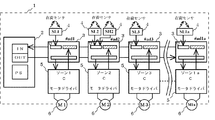
図1に示すように、この実施形態に係る搬送システム1は、モータ駆動のローラと、前記モータ駆動のローラから動力伝達手段により連動する複数の連動ローラにより構成される複数の搬送ユニットと、を備える。また、伝送信号のスタート信号やエンド信号とこれに続くクロック信号を生成する仲介局2と伝送線DP、DNにつながる複数のデータ処理子局3と、在荷センサ4と、モータドライバ5、駆動モータ6とを備える。
As shown in FIG. 1, the
データ処理子局3は、共通の伝送線DP、DNにデータ処理子局入出力部11を介して接続しており、I/Oバス17からローカルバス16を介してCPU13、RAM15に接続し、信号データの授受を行っている。すなわち、伝送線DP、DNに伝送されている、データ処理子局3の複数局に関する監視・制御データから、所定の局に関する情報を取り込むと共に、自局に関する情報を伝送線DP、DNに出力する。
The data
CPU13は、ROM14に格納された制御プログラムに従って、取り込まれた所定の局に関する情報に基づき、自局の制御・監視を判断する。制御内容は、RAM15の出力データ(OUT)として、ROM14に格納された制御プログラムに従ってCPU13に操作され、I/Oバス18を介して制御出力部20から後述のモータドライバ5に出力される。また、前記ローカルバス16及びI/Oバス17を経て、データ処理子局入出力部11を介し自局に関する情報として伝送線DP、DNに出力する。
The CPU 13 determines control / monitoring of its own station based on the acquired information on the predetermined station according to the control program stored in the
また、CPU13は、センサ入力部19に接続された在荷センサ4から取り込んだ監視信号を、前記データ処理子局入出力部11を介して伝送線DP、DNに出力する。センサ入力部19は、I/Oバス18及びローカルバス16を介してCPU13、RAM15と信号データの授受を行う。センサ部入力部19は、また、モータドライバ5の速度データ、過負荷信号、ドライバ故障信号、モータ故障信号を取り込み、これら速度データ、過負荷信号、ドライバ故障信号、モータ故障信号も前記監視信号と同様、自局に関する情報として伝送線DP、DNに出力する。
Further, the CPU 13 outputs a monitoring signal taken from the in-
仲介局2は、スタート信号及びこれに続くクロック信号を生成し、伝送線DP、DNに出力している。データ処理子局3は、このクロック数をカウントすることにより、どのデータ値がどのデータ処理子局のものであるかを認識できる。なお、伝送信号の詳細は、後述する。
The
次に、このシステムの具体的な動作について説明する。複数のデータ処理子局3の各々には、アドレスナンバーが付与されており、図1の例ではゾーン1のモータドライバ5にアドレスナンバー1(#ad1)のデータ処理子局3が接続されている。また、反射型のセンサSL1で構成される在荷センサ4が接続され、この在荷センサ4の入力信号と前記モータドライバ5の速度データ、過負荷信号、ドライバ故障信号、モータ故障信号をセンサ入力部19から取り込み、前述のように、伝送線DP、DNに出力する。また、他局の情報に基づく判断に応じたゾーン1の搬送速度指示信号が制御出力部20からモータドライバ5に出力される。モータドライバ5は、データ処理子局3の制御出力部20からの指示信号で駆動モータ6の回転数を設定し、ゾーン1の上にある被搬送物を次のゾーン2に引き渡す。
Next, a specific operation of this system will be described. Each of the plurality of data
アドレスナンバー2(#ad2)のデータ処理子局3は、監視信号の取り込みと制御信号の出力はゾーン1と同様であるが、前記センサSL1と同じ反射型のセンサSL2に加え、同じく反射型の在荷高さセンサSH2を有する在荷センサ4を備える。在荷高さセンサSH2は一定以上の高さを有する被搬送物を検知するセンサである。センサSL2と在荷高さセンサSH2の双方の信号を含む在荷センサ4からの入力信号は、前記#ad1のデータ処理子局3と同様に、伝送線DP、DNに出力される。
そこで、例えば在荷高さセンサSH2でとらえた信号によって、つまり在荷高さによって、当該在荷の搬送方向を分岐し、分別搬送を行うか、分離・集合を行う制御入力とすることができる。
The data
Therefore, for example, depending on the signal captured by the stock height sensor SH2, that is, depending on the stock height, the transport direction of the stock can be branched and used as a control input for performing separate transport or separation / collection. .
図2の実施例では、直進方向の搬送方向から経路変更方向のゾーン1aに設けられたアドレスナンバー1a(#ad1a)のデータ処理子局3は、在荷高さセンサSH2の検知信号が制御・監視データに反映され、その情報を得ると、ゾーン1から被搬送物を引き継ぎ、ゾーン1aの搬送系を作動させるモータドライバ5を作動させる。
In the embodiment of FIG. 2, the data
図3には、背高の被搬送物(以下、被搬送物Hという)がゾーン2まで搬送された際、データ処理子局3の内部に記憶されるデータが示されている。図3において、伝送線DP、DNから取り込まれた情報のうち各ゾーンの状態を示すものは「IN」と、制御出力部20への出力情報は「OUT」と示されている。なお、「OUT」の情報は、システム全体の大まかな稼動可否を制御するためのもので、各ゾーンにおける細かな状態を制御するものではなく、稼動可能であればRNが「1」と、稼動不可であればSPが「1」となる。この実施例では、全てのゾーンが稼動可能な状態であるため、「OUT」の情報は、全てRNが「1」となっている。太枠は、自局の情報を示している。
FIG. 3 shows data stored in the data
まず、#ad1では、ゾーン2に送り出された前記被搬送物Hに続いて別の被搬送物(以下、被搬送物Nという)が検知されているため、INのSL1が「1」(検知有り)となる。また、モータドライバ5の速度が低速であることのデータが、INのL1に「1」なる。更に、このゾーンは稼動可能であることから、OUTのRN1が「1」となる。
First, in # ad1, since another transported object (hereinafter referred to as transported object N) is detected following the transported object H sent to
また、#ad2は、前記被搬送物HがセンサSL1に検知された段階でその受け入れ準備状態となっており、モータドライバ5が駆動され低速運転状態となっていることから、INのL2が「1」となる。また、被搬送物Hが検知されていることから、SL2とSH2のそれぞれも「1」となる。#ad3は、被搬送物が搬送されるまでに時間があることから、モータドライバ5は停止状態とされており、全てのIN情報は「0」となっている。
Also, # ad2 is in a state where it is ready to receive the conveyed object H when it is detected by the sensor SL1, and since the
更に、#ad1aでは、#ad2のSH2が「1」となっていることから、前記被搬送物Hを受け入れるために、モータドライバ5の駆動がなされ低速運転状態となっており、INのL1aが「1」となる。
Further, in # ad1a, since SH2 of # ad2 is “1”, the
一方、在荷高さセンサSH2が在荷検知をしなかった場合、つまり、一定以上の高さを有する被搬送物でない場合には、直進方向のゾーン3に設置されたアドレスナンバー3(#ad3)のデータ処理子局3が、その情報を得て、駆動モータM3のモータドライバ5を作動させ、被搬送物の直進搬送を続ける。なお、図3において、SH1、SH3等は、在荷高さセンサを備えないアドレスについても、同センサ信号のために用意された入力部分であり、在荷高さセンサを容易に追加することができるものとなっている。ただし、この実施例では、実際に設置されていない在荷高さセンサに対応する信号入力部分は「0」となっている。
On the other hand, if the occupancy height sensor SH2 does not detect the occupancy, that is, if it is not a conveyed object having a certain height or more, the address number 3 (# ad3) installed in the
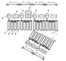
第一モータM1は、ゾーン1の駆動モータ7であり、これに連動する3個の連動ローラ8と共にゾーン1を構成する。駆動モータと連動ローラは、連動ローラの端部が、ベルトによる動力伝達のためのプーリーを兼ねており、回転を伝達しながらローラ上の荷物を搬送する。また、前記連動ローラの反対側の端部もベルトによる動力伝達のためのプーリーを兼ねており、続く連動ローラにベルトによって動力を伝達する。同様に、第二モータM2は、ゾーン2の駆動モータ7と3個の連動ローラ8と共にゾーン2を構成する。更に第三モータM3、第四モータM4は、直進方向のゾーンを形成し、直進移動9方向の搬送を受け持っている。一方、分岐方向10のゾーンには、在荷センサSL2-1、続くゾーンには、在荷センサSL2-2が在荷状態を確認する監視センサとなっている。分岐方向10のデータ処理子局3が始動及び速度変更の判断を行った場合、分岐動作搬送が行われる。
The first motor M1 is the
更に、図3に示すように、被制御部22からモータドライバ5に速度制御信号を受け渡し、駆動モータ6を動作させる。また、モータドライバで駆動モータ6の過負荷やドライバ回路異常が発生した場合のエラー信号をセンサ入力部19に戻される。そして、その情報が伝送線DP、DNに送出され、故障やエラー検知時のライン制御が行われる。例えば、#ad1の在荷センサ4は、センサ入力部19に監視信号を取り込み、I/Oバス18からCPU13の制御下で、監視データをRAM15のアドレス1の監視信号領域に記憶する。また、CPU13はROM14に記憶しているプログラムにより、RAM17に記憶されている制御出力データを用い、論理演算の後、ローカルバス16経由I/Oバス18から制御出力部20に信号を送出する。論理演算には、増速、減速時の判断も含み、前工程からの速度引継や増速・減速を円滑に行う。被制御部22は、モータドライバ5に対し、増速、減速、定速、停止、前進、後退の制御を行う制御信号を出力する。駆動モータは、サーボモータ、ACモータであり、前記被制御部の信号に従い、増速、減速、定速、停止、前進、後退の動作を行う。ここでいう、後退とは、通常の搬送は前進方向への移送が主であるが、たとえば屋外の搬送設備である場合、または、清浄度、温度を条件下で保持を要する在荷にあっては、進行先の工程で故障が発生した場合の待機場所への後退を意味するものである。この動作により、在荷物の保冷、清浄度、湿度などを規定状態に保持することができる。
Further, as shown in FIG. 3, a speed control signal is transferred from the controlled
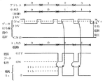
図4に、この搬送制御システム1の伝送信号のタイムチャート図を示す。
図4には、仲介局1から出力される監視・制御データの信号のアドレス0〜3番地のデータ値が「0101」であり、アドレス0〜3番地を付与されたセンサ部7からの入力が「0011」である場合が示されている。なお、ここにいうアドレスとは、前記データ処理子局3に付与されたアドレスではなく、監視・制御データの信号における位置を表現するためのものである。
FIG. 4 shows a time chart of transmission signals of the
In FIG. 4, the data value of
この実施例における直列のパルス状電圧信号では、クロックCKの1周期(t0)、即ち、各アドレスを少なくとも入力期間(i)及びこれに続く出力期間(O )とに区分する。図4において、データ値が「0」となるアドレス0番地及びアドレス2番地では、「ロウレベル」となる前の3/4周期が入力期間と、残る1/4周期が出力期間となる。また、データ値が「1」となるアドレス1番地及びアドレス3番地では、「ロウレベル」となる前の1/4周期が入力期間と、残る3/4周期が出力期間となる。入力期間では、電流信号Isからなる監視データ信号が重畳され、仲介局入力部18は、この重畳された監視データ信号を抽出する。一方、出力期間では、パルス幅変調(PWM)した制御信号が重畳されることになる。なお、仲介局出力部15は、前の出力時に得た監視信号を制御信号として取り込んで、この出力期間において、制御データ信号を直列のパルス状電圧信号に重畳して伝送線DP、伝送線DNに出力する。
In the serial pulsed voltage signal in this embodiment, one cycle (t0) of the clock CK, that is, each address is divided into at least an input period (i) and an output period (O 2) subsequent thereto. In FIG. 4, at
以上から判るように、この制御・監視信号伝送システムにおいては、前述のように入力信号(センサ部7からの監視信号)と出力信号(モータドライバ5への制御信号)とを単純に1対1に対応させて伝送する。これにより、従来の制御部及び親局を省略した簡易な構成を実現して、保守を容易とし、コストを安価なものとすることができる。更に、伝送のサイクルにおける各々の入出力アドレス毎に、電流信号からなる入力信号により、パルス幅変調信号からなる出力信号を制御する。これにより、入力信号及び出力信号の事実上の双方向(実際には、後述するように、伝送の瞬間は双方向ではない)の伝送を行い、電力線を省略することができる。 As can be seen from the above, in this control / monitor signal transmission system, the input signal (monitor signal from the sensor unit 7) and the output signal (control signal to the motor driver 5) are simply one-to-one as described above. Transmit in correspondence with As a result, a simple configuration in which the conventional control unit and master station are omitted can be realized, maintenance can be facilitated, and cost can be reduced. Further, for each input / output address in the transmission cycle, an output signal consisting of a pulse width modulation signal is controlled by an input signal consisting of a current signal. As a result, the transmission of the input signal and the output signal in a virtually bidirectional manner (in practice, the moment of transmission is not bidirectional, as will be described later), and the power line can be omitted.
また、この例のように、監視信号として電流信号を用い制御信号としてパルス幅変調された電圧信号を用いること(電流変調監視信号とパルス幅変調制御信号との組み合わせ)により、電圧ノイズの大きい悪条件の製造工場等において、高い信頼性の伝送制御システムを実現することができる。 Further, as in this example, by using a current signal as a monitor signal and a pulse width modulated voltage signal as a control signal (combination of a current modulation monitor signal and a pulse width modulation control signal), the voltage noise is greatly degraded. A highly reliable transmission control system can be realized in a manufacturing plant or the like under conditions.
なお、データ処理子局3の使用する電力は、共通の伝送線DP、DNから電源部12を介して供給(Vcp、Vcg)を受ける。この電源を伝送線に重畳する方式は、配線の省略所謂省配線技術であり、配線の低減ができる。
The power used by the data
この実施例における制御信号は、電源電圧Vx、即ち24Vのレベルのパルス状電圧と、この電源電圧よりは(絶対値が)小さく他の回路部分におけるハイレベル信号よりも(絶対値が)大きいレベルである「高電位のロウレベル」、即ち19Vのレベルのパルス状電圧とで構成されている。そのため、他の回路部分(例えばCMOS論理の回路部分)におけるCMOSハイレベル信号5Vよりも十分に大きい。クロックCK、即ちパルス状電圧のハイレベルとロウレベルとの電位差Vsは5Vあるので、しきい値をその中間値(DN信号線9を基準レベルとすると21.5V)とすることにより、これらは十分に識別できる。換言すれば、電位差Vsは他の回路部分(例えばCMOS論理の回路部分)におけるCMOS論理振幅に等しい。従って、直列のパルス状電圧信号は、デューティ比50%で電位差Vsのクロックをそのままレベルシフトして、制御データ信号に応じてパルス幅変調したものと考えてよい。一方、このパルス幅変調され高電位で振幅制限されたクロックによれば、伝送される平均電力により実現される平均電源電圧は、図4に一点鎖線で示すように、およそ当該振幅の中心値である+21.5Vと言う非常に高い値となる。従って、電力線P等を省略しても、複数の子局4の各々が動作するのに十分な電力容量をこれらに伝送することができる。
The control signal in this embodiment includes a power supply voltage Vx, that is, a pulsed voltage having a level of 24V, and a level (absolute value) that is smaller (absolute value) than this power supply voltage and greater (absolute value) than high-level signals in other circuit portions. The “high potential low level”, that is, a 19 V level pulse voltage. Therefore, it is sufficiently larger than the CMOS high level signal 5V in other circuit parts (for example, a circuit part of CMOS logic). Since the potential difference Vs between the high level and the low level of the clock CK, that is, the pulse voltage is 5V, the threshold value is set to its intermediate value (21.5V when the DN signal line 9 is the reference level). Can be identified. In other words, the potential difference Vs is equal to the CMOS logic amplitude in another circuit part (for example, a CMOS logic circuit part). Therefore, it can be considered that the serial pulse-shaped voltage signal is obtained by level-shifting the clock of the potential difference Vs with a duty ratio of 50% and performing pulse width modulation according to the control data signal. On the other hand, according to this pulse width modulated and amplitude-limited clock with a high potential, the average power supply voltage realized by the transmitted average power is approximately the center value of the amplitude as shown by the one-dot chain line in FIG. It is a very high value of + 21.5V. Therefore, even if the power line P or the like is omitted, a power capacity sufficient for each of the plurality of
図5に、この搬送制御システム1の伝送信号の配列図を示す。
図5(a)及び図5(b)はゾーン1及び2に対応した伝送信号の配列を、図5(c)はゾーン1a及び1bに対応した伝送信号の配列を示したものである。図の上段が各ゾーンの状態を示す入力(IN)を示し、下段が大まかな稼動可否を制御する出力信号(OUT)を示す。この実施例では、全てのゾーンが稼動可能な状態であるため、「OUT」の情報は、全てRNが「1」となる。
図5に示す伝送信号は、スタート信号STから始まり、アドレス1(#ad1)の入出力信号からアドレス1b(#ad1b)の入出力信号までが1サイクルとして続いている。なお、図5(a)は前記被搬送物Hがゾーン1にある状態の信号、図5(b)及び図5(c)は被搬送物Hがゾーン2に送り出された状態の信号である。
FIG. 5 shows an arrangement diagram of transmission signals of the
5 (a) and 5 (b) show the arrangement of transmission signals corresponding to
The transmission signal shown in FIG. 5 starts from the start signal ST and continues from the input / output signal at address 1 (# ad1) to the input / output signal at
この例では、まず、#ad1のデータ処理子局3が、低速運転で被搬送物Hを搬送している。この時点で、被搬送物Hはまだゾーン2に送り出されておらず、図5(a)の入力信号では、#ad1の在荷センサを示すSL1と低速を示すL1が「1」となっており、#ad2の在荷センサを示すSL2及びSH2が「0」となっている。ただし、ゾーン2では、被搬送物HがセンサSL1に検知された段階でその受け入れ準備状態となっており、搬送受け入れのための低速運転が行われているため、低速を示すL2が「1」となっている。
In this example, first, the data
被搬送物Hがゾーン2まで搬送されると、被搬送物Hがそこで検知るため、図5(b)において、#ad2のSL2及びSH2が「1」となる。この時点で、ゾーン1では、被搬送物Hに続いて別の被搬送物Nが検知されているため、#ad1のSL1が「1」となる。また、この時、ゾーン1a及び1bでは、#ad2のSH2が「1」となっていることから、被搬送物Hを受け入れるために低速運転状態となっており、図5(c)において、#ad1aのL1aと、#ad1bのL1bが「1」となる。
When the transported object H is transported to the
この実施例では、直列のパルス状電圧信号において入力期間及びこれに続く出力期間とに区分し、入力期間はデータ処理子局3から入力し、出力期間は仲介局2から出力するものとしているため、図5に示す信号配列となる。しかしながら、本発明の搬送制御システムでは、仲介局2よりも高度な演算処理機能を備える親局を使用することもでき、その場合の伝送信号の配列は、親局における伝送方式によるものとなる。
In this embodiment, the serial pulsed voltage signal is divided into an input period and an output period following the input period. The input period is input from the data
一方、仲介局2は、使用状況に応じて、システム全体の入力データを記憶保持する入力用記憶保持エリアと、システム全体の出力データを記憶保持する出力用記憶保持エリアを有するもとしてもよい。そして、データ処理子局3から出力された監視信号の監視データを入力用記憶保持エリアに記憶する。続いて、ここで記憶したデータを、1クロック毎にまたは伝送データの1周期毎(ブロック毎)に出力用記憶保持エリアに書き込む(上書記憶する)。なお、出力用記憶保持エリアへの書き込みが終了した後、入力用記憶保持エリアのデータは、新たな入力データにより書換える。そして、出力用記憶保持エリアへ書き込まれたデータを、伝送開始のスタート信号と伝送終了信号エンドの間に挟み込み、伝送線DP、DNに送出することにより、PLCなど中央制御装置に制御を依存することなく、基本的な搬送制御を容易に行うことができる。
On the other hand, the
本発明によれば、PLCなどの中央制御装置の処理待ちにより制御における遅延が生じることなく、搬送ゾーン間の制御を円滑かつ、省エネルギーで 搬送システムの制御を行うことができる。 According to the present invention, it is possible to control the transport system smoothly and with energy saving control between the transport zones without causing a delay in control due to waiting for processing of a central control device such as a PLC.
1:搬送システム、 2:仲介局、3:データ処理子局、 4:在荷センサ、
5:モータドライバ、 6:駆動モータ、 7: 駆動ローラ、 8:連動ローラ、
9:直進移動、 10:分岐方向、 11: データ処理子局入出力部、
12:電源部、 13:CPU、 14:ROM、15:RAM 、
16:ローカルバス、 17、18I/Oバス、 19:センサ入力部、
20:制御出力部、 21: センサ部、 22:被制御部
1: transport system, 2: brokerage station, 3: data processing slave station, 4: in-stock sensor,
5: Motor driver, 6: Drive motor, 7: Drive roller, 8: Interlocking roller,
9: Straight travel, 10: Branch direction, 11: Data processing slave station input / output unit,
12: Power supply unit, 13: CPU, 14: ROM, 15: RAM,
16: Local bus, 17, 18 I / O bus, 19: Sensor input section,
20: Control output unit, 21: Sensor unit, 22: Controlled unit
Claims (4)
前記データ処理子局は、前記共通の伝送線に伝送されている、伝送の開始を示すスタート信号及びこれに続けて送出される前記データ処理子局の複数局に関する監視・制御データを構成するクロック信号に基づき、前記スタート信号を起点とし、前記クロック信号により順次アドレスカウンタを更新して伝送同期し、前記監視・制御データから、所定の局に関する情報を取り込み自局の制御・監視を判断し調整すると共に、自局に関する情報を前記共通の伝送線に出力し、
前記データ処理子局から前記共通の伝送線に出力された前記自局に関する情報が、前記監視・制御データの一部として他局に取り込まれ他局の制御・監視因子となり、
前記監視・制御データの信号は、前記共通の伝送線に接続された仲介局または親局から前記データ処理子局にデータを出力する出力期間と、前記データ処理子局から前記仲介局または前記親局にデータが入力される入力期間とを有することを特徴とする搬送制御システム。 Comprising a plurality of data processing slave stations connected via a common transmission line;
The data processing slave station is transmitted to the common transmission line, a start signal indicating the start of transmission, and a clock constituting monitoring / control data relating to a plurality of stations of the data processing slave station transmitted subsequently based on the signal, the start signal as a starting point, the sequentially updated address counter transmission synchronized by the clock signal, before the Ki監 view and control data, determines control and monitoring of the own station captures information about the predetermined station And output information about the local station to the common transmission line,
Information about the own station output from the data processing slave station to the common transmission line is taken into another station as a part of the monitoring / control data and becomes a control / monitoring factor of the other station,
The monitoring / control data signal includes an output period in which data is output from the intermediary station or master station connected to the common transmission line to the data processing slave station, and the intermediary station or the master station from the data processing slave station. A conveyance control system comprising an input period during which data is input to a station.
Priority Applications (5)
| Application Number | Priority Date | Filing Date | Title |
|---|---|---|---|
| JP2008220156A JP4979658B2 (en) | 2008-08-28 | 2008-08-28 | Transport control system and transport control method |
| AT09166464T ATE550700T1 (en) | 2008-08-28 | 2009-07-27 | FUNDING CONTROL SYSTEM AND FUNDING CONTROL METHOD |
| EP09166464A EP2159655B1 (en) | 2008-08-28 | 2009-07-27 | Conveyance Control System and Conveyance Control Method |
| US12/533,177 US8396587B2 (en) | 2008-08-28 | 2009-07-31 | Conveyance control system and conveyance control method |
| KR1020090079649A KR101215430B1 (en) | 2008-08-28 | 2009-08-27 | Conveyance control system and conveyance control method |
Applications Claiming Priority (1)
| Application Number | Priority Date | Filing Date | Title |
|---|---|---|---|
| JP2008220156A JP4979658B2 (en) | 2008-08-28 | 2008-08-28 | Transport control system and transport control method |
Publications (2)
| Publication Number | Publication Date |
|---|---|
| JP2010052900A JP2010052900A (en) | 2010-03-11 |
| JP4979658B2 true JP4979658B2 (en) | 2012-07-18 |
Family
ID=41479298
Family Applications (1)
| Application Number | Title | Priority Date | Filing Date |
|---|---|---|---|
| JP2008220156A Active JP4979658B2 (en) | 2008-08-28 | 2008-08-28 | Transport control system and transport control method |
Country Status (5)
| Country | Link |
|---|---|
| US (1) | US8396587B2 (en) |
| EP (1) | EP2159655B1 (en) |
| JP (1) | JP4979658B2 (en) |
| KR (1) | KR101215430B1 (en) |
| AT (1) | ATE550700T1 (en) |
Families Citing this family (14)
| Publication number | Priority date | Publication date | Assignee | Title |
|---|---|---|---|---|
| US8887897B2 (en) * | 2010-08-31 | 2014-11-18 | Itoh Denki Co., Ltd. | Fault diagnosis method for roller conveyor, roller conveyor, and controller for conveyor |
| JP5879520B2 (en) * | 2011-11-07 | 2016-03-08 | パナソニックIpマネジメント株式会社 | Communication system and transmission unit used therefor |
| US20150005927A1 (en) * | 2012-02-10 | 2015-01-01 | Cassidian Airborne Solutions Gmbh | Flexible, scalable freight loading system |
| US9446907B2 (en) | 2012-03-19 | 2016-09-20 | Itoh Denki Co., Ltd. | Zone controller and conveyor device |
| JP5882810B2 (en) * | 2012-03-29 | 2016-03-09 | 伊東電機株式会社 | Conveying device and article storage device |
| CH707879A1 (en) * | 2013-04-11 | 2014-10-15 | Ferag Ag | Control of drives of conveyor sections of a conveyor system. |
| US10322883B2 (en) * | 2014-11-18 | 2019-06-18 | Itoh Denki Co. | Conveyor device, conveyor system, zone controller, CAD device, and method for manufacturing conveyor device |
| WO2017037774A1 (en) * | 2015-08-28 | 2017-03-09 | 株式会社エニイワイヤ | Conveyance system |
| WO2017061088A1 (en) * | 2015-10-08 | 2017-04-13 | ソニー株式会社 | Servo motor, servo motor system, and power supply method |
| EP3441832A1 (en) * | 2017-08-07 | 2019-02-13 | Wieland Electric GmbH | Modular memory programmable controller |
| JP7149607B2 (en) * | 2019-10-25 | 2022-10-07 | 伊東電機株式会社 | conveyor system |
| KR20210051688A (en) * | 2019-10-31 | 2021-05-10 | 세메스 주식회사 | Object transport device and method of controlling the same |
| CN111830893A (en) * | 2019-12-03 | 2020-10-27 | 上海稳擎科技有限公司 | Equipment operation and maintenance monitoring system |
| US11597604B1 (en) * | 2022-03-02 | 2023-03-07 | Jakob Simon | Conveyor safely guard modules |
Family Cites Families (20)
| Publication number | Priority date | Publication date | Assignee | Title |
|---|---|---|---|---|
| JPS6196390A (en) * | 1984-10-18 | 1986-05-15 | 株式会社 タクマ | Roller kiln |
| JPH07172549A (en) * | 1993-12-17 | 1995-07-11 | Daifuku Co Ltd | Conveyor device |
| JPH08143133A (en) * | 1994-11-17 | 1996-06-04 | Toyo Kanetsu Kk | Transfer device control method and transfer device |
| JP3458026B2 (en) * | 1995-09-14 | 2003-10-20 | Nke株式会社 | Control and monitoring system |
| JP3374738B2 (en) * | 1998-01-07 | 2003-02-10 | 株式会社ダイフク | Conveyor equipment |
| JP2001106331A (en) * | 1999-10-08 | 2001-04-17 | Kyowa Seisakusho:Kk | Carrying control system |
| WO2001084259A1 (en) * | 2000-04-27 | 2001-11-08 | Rockwell Technologies, Llc | Driver board control system for modular conveyor with address-based network for inter-conveyor communication |
| US6701214B1 (en) * | 2000-04-27 | 2004-03-02 | Rockwell Automation Technologies, Inc. | Driver board control system for modular conveyer with address-based network for inter-conveyor communication |
| US6574515B1 (en) * | 2000-05-12 | 2003-06-03 | Rosemount Inc. | Two-wire field-mounted process device |
| JP2002012315A (en) * | 2000-06-30 | 2002-01-15 | Algo System:Kk | Conveyor system |
| WO2003000574A1 (en) * | 2001-06-20 | 2003-01-03 | Itoh Electric Company Limited | Zone controller |
| US6827202B2 (en) * | 2001-12-21 | 2004-12-07 | Balluff, Inc. | Methods and apparatus for controlling conveyor zones |
| JP3795392B2 (en) * | 2001-12-28 | 2006-07-12 | 株式会社 エニイワイヤ | Control and monitoring signal transmission system |
| JP4064140B2 (en) | 2002-03-29 | 2008-03-19 | 株式会社ダイフク・ロジスティック・テクノロジー | Load transfer conditions setting method for load transfer equipment |
| US7167527B1 (en) * | 2002-05-02 | 2007-01-23 | Integrated Memory Logic, Inc. | System and method for multi-symbol interfacing |
| JP3927933B2 (en) | 2003-07-31 | 2007-06-13 | 株式会社ダイフク・ロジスティック・テクノロジー | Conveyor centering device |
| JP4322071B2 (en) * | 2003-09-04 | 2009-08-26 | 株式会社 エニイワイヤ | Control and monitoring signal transmission system |
| WO2007055083A1 (en) | 2005-11-14 | 2007-05-18 | Anywire Corporation | Control/monitor signal transmission system |
| JP4808118B2 (en) * | 2006-08-25 | 2011-11-02 | 株式会社 エニイワイヤ | Input / output terminal |
| US8050795B2 (en) * | 2007-03-20 | 2011-11-01 | Donald L. Dollens | Conveyor drive control system |
-
2008
- 2008-08-28 JP JP2008220156A patent/JP4979658B2/en active Active
-
2009
- 2009-07-27 EP EP09166464A patent/EP2159655B1/en active Active
- 2009-07-27 AT AT09166464T patent/ATE550700T1/en active
- 2009-07-31 US US12/533,177 patent/US8396587B2/en active Active
- 2009-08-27 KR KR1020090079649A patent/KR101215430B1/en active IP Right Grant
Also Published As
| Publication number | Publication date |
|---|---|
| EP2159655B1 (en) | 2012-03-21 |
| KR101215430B1 (en) | 2012-12-26 |
| JP2010052900A (en) | 2010-03-11 |
| EP2159655A3 (en) | 2011-01-19 |
| US20100058098A1 (en) | 2010-03-04 |
| EP2159655A2 (en) | 2010-03-03 |
| ATE550700T1 (en) | 2012-04-15 |
| US8396587B2 (en) | 2013-03-12 |
| KR20100027021A (en) | 2010-03-10 |
Similar Documents
| Publication | Publication Date | Title |
|---|---|---|
| JP4979658B2 (en) | Transport control system and transport control method | |
| JP4798554B2 (en) | Driving control system and control method for traveling vehicle | |
| JP6433157B2 (en) | Tape feeder and self-diagnosis method of sensor function thereof | |
| JPWO2003002436A1 (en) | Zone controller | |
| US9643232B2 (en) | Servo press line operation method and servo press line operation control device | |
| US9694986B2 (en) | Transport device and transport method for transporting a fragile object | |
| JP2009087138A (en) | Transport system, transport vehicle management device, and transport control method | |
| JP4998162B2 (en) | Interprocess conveyor system | |
| CN111153144B (en) | Carrier backflow method, device and equipment | |
| WO2017037774A1 (en) | Conveyance system | |
| JPH0632883B2 (en) | Manufacturing control method of goods | |
| KR101081935B1 (en) | Apparatus for controlling multi-axis motion based on a plurality of channels network and method for the same | |
| US8578077B2 (en) | Group master communication system and method for serially transmitting data in automation systems | |
| CN110832414B (en) | Conveyor system, method of operating a conveyor system and flow device for use in such a conveyor system | |
| JP6497203B2 (en) | Automatic transfer system | |
| JP5418039B2 (en) | Sorting system | |
| JP2002012315A (en) | Conveyor system | |
| CN203095049U (en) | Stochastic control device for belt conveyors | |
| JP2003212334A (en) | Conveyor system | |
| JP2006248682A (en) | Conveyor device and its control method | |
| KR102508543B1 (en) | Conveyor Controller based on Non PLC | |
| CN112711217A (en) | Master-slave configurable PLC controller based on CAN bus | |
| KR20240027489A (en) | Transfer Robot System and Control Methods for Transfer Robot System | |
| JP2004231359A (en) | Control system of conveyance means |
Legal Events
| Date | Code | Title | Description |
|---|---|---|---|
| A621 | Written request for application examination |
Free format text: JAPANESE INTERMEDIATE CODE: A621 Effective date: 20100514 |
|
| A977 | Report on retrieval |
Free format text: JAPANESE INTERMEDIATE CODE: A971007 Effective date: 20101020 |
|
| A131 | Notification of reasons for refusal |
Free format text: JAPANESE INTERMEDIATE CODE: A131 Effective date: 20101102 |
|
| A521 | Request for written amendment filed |
Free format text: JAPANESE INTERMEDIATE CODE: A523 Effective date: 20101206 |
|
| A131 | Notification of reasons for refusal |
Free format text: JAPANESE INTERMEDIATE CODE: A131 Effective date: 20110830 |
|
| A521 | Request for written amendment filed |
Free format text: JAPANESE INTERMEDIATE CODE: A523 Effective date: 20110926 |
|
| TRDD | Decision of grant or rejection written | ||
| A01 | Written decision to grant a patent or to grant a registration (utility model) |
Free format text: JAPANESE INTERMEDIATE CODE: A01 Effective date: 20120417 |
|
| A01 | Written decision to grant a patent or to grant a registration (utility model) |
Free format text: JAPANESE INTERMEDIATE CODE: A01 |
|
| A61 | First payment of annual fees (during grant procedure) |
Free format text: JAPANESE INTERMEDIATE CODE: A61 Effective date: 20120417 |
|
| FPAY | Renewal fee payment (event date is renewal date of database) |
Free format text: PAYMENT UNTIL: 20150427 Year of fee payment: 3 |
|
| R150 | Certificate of patent or registration of utility model |
Ref document number: 4979658 Country of ref document: JP Free format text: JAPANESE INTERMEDIATE CODE: R150 Free format text: JAPANESE INTERMEDIATE CODE: R150 |
|
| S531 | Written request for registration of change of domicile |
Free format text: JAPANESE INTERMEDIATE CODE: R313531 |
|
| R350 | Written notification of registration of transfer |
Free format text: JAPANESE INTERMEDIATE CODE: R350 |
|
| R250 | Receipt of annual fees |
Free format text: JAPANESE INTERMEDIATE CODE: R250 |
|
| R250 | Receipt of annual fees |
Free format text: JAPANESE INTERMEDIATE CODE: R250 |
|
| R250 | Receipt of annual fees |
Free format text: JAPANESE INTERMEDIATE CODE: R250 |
|
| R250 | Receipt of annual fees |
Free format text: JAPANESE INTERMEDIATE CODE: R250 |
|
| R250 | Receipt of annual fees |
Free format text: JAPANESE INTERMEDIATE CODE: R250 |
|
| R250 | Receipt of annual fees |
Free format text: JAPANESE INTERMEDIATE CODE: R250 |
|
| R250 | Receipt of annual fees |
Free format text: JAPANESE INTERMEDIATE CODE: R250 |
|
| R250 | Receipt of annual fees |
Free format text: JAPANESE INTERMEDIATE CODE: R250 |
|
| R250 | Receipt of annual fees |
Free format text: JAPANESE INTERMEDIATE CODE: R250 |
|
| R250 | Receipt of annual fees |
Free format text: JAPANESE INTERMEDIATE CODE: R250 |