JP4969254B2 - Video display system, video display device, and video display method - Google Patents
Video display system, video display device, and video display method Download PDFInfo
- Publication number
- JP4969254B2 JP4969254B2 JP2007010675A JP2007010675A JP4969254B2 JP 4969254 B2 JP4969254 B2 JP 4969254B2 JP 2007010675 A JP2007010675 A JP 2007010675A JP 2007010675 A JP2007010675 A JP 2007010675A JP 4969254 B2 JP4969254 B2 JP 4969254B2
- Authority
- JP
- Japan
- Prior art keywords
- video display
- control
- communication terminal
- data
- unit
- Prior art date
- Legal status (The legal status is an assumption and is not a legal conclusion. Google has not performed a legal analysis and makes no representation as to the accuracy of the status listed.)
- Expired - Fee Related
Links
Images


Landscapes
- Two-Way Televisions, Distribution Of Moving Picture Or The Like (AREA)
- Telephonic Communication Services (AREA)
Description
本発明は、映像表示システムに関し、特に、コンテンツの表示制御を行なう映像表示システムに関する。 The present invention relates to a video display system, and more particularly to a video display system that performs display control of content.
近年、宅内の複数種類の装置間において、互いにデータ通信を可能とするための規格(以下、異装置間通信規格ともいう)に準拠した装置が普及しつつある。異装置間通信規格は、たとえば、DLNA(Digital Living Network Alliance)規格である。異装置間通信規格に準拠した装置は、たとえば、テレビ受像機、HDD(Hard disk drive)レコーダ、オーディオ装置等である。また、異装置間通信規格に準拠した装置は、一般的に、ルータ等のネットワーク機器を介して、インターネット等のネットワークにも接続可能となっている。 In recent years, devices conforming to a standard (hereinafter also referred to as inter-device communication standard) for enabling data communication with each other among a plurality of types of devices in a home are becoming widespread. The inter-device communication standard is, for example, a DLNA (Digital Living Network Alliance) standard. Devices conforming to the inter-device communication standard are, for example, a television receiver, an HDD (Hard disk drive) recorder, an audio device, and the like. In addition, a device compliant with the inter-device communication standard is generally connectable to a network such as the Internet via a network device such as a router.
また、ネットワークに接続可能な異装置間通信規格に準拠した装置は、リモコンで操作可能な装置であるのが一般的である。そのため、リモコンで操作可能であり、かつ、ネットワークに接続可能な複数種類の装置を、1つの装置で操作することが要求される。 In general, a device that conforms to a communication standard between different devices that can be connected to a network is a device that can be operated by a remote controller. Therefore, it is required to operate a plurality of types of devices that can be operated with a remote controller and can be connected to a network with a single device.
特開2002−135810号公報(特許文献1)には、インターネット等のネットワークに接続可能であって、携帯電話等の通信端末装置を、ネットワークに接続可能なテレビを操作するためのリモコンとして使用する技術(以下、第1の先行技術ともいう)が開示されている。
携帯電話等の通信端末装置を、テレビ等の映像表示装置のリモコンとして使用することにより、映像表示装置の専用リモコンを使用する必要がなくなる。そのため、ユーザに多くの手間をかけることなく、多種多様なコンテンツを、迅速に映像表示装置に表示させることができる。ここで、多くの手間とは、たとえば、携帯電話と、専用リモコンとを持ちかえるといった手間である。 By using a communication terminal device such as a mobile phone as a remote control for a video display device such as a television, it is not necessary to use a dedicated remote control for the video display device. Therefore, various types of content can be quickly displayed on the video display device without much time and effort for the user. Here, much trouble is, for example, trouble of holding a mobile phone and a dedicated remote controller.
最近では、映像表示装置に表示されているコンテンツに関連する関連情報を参照できる技術が普及している。たとえば、サッカーの試合の番組のコンテンツを、映像表示装置に表示させているときに、関連情報としてのサッカーの試合の出場選手のプロフィール等を映像表示装置に表示させる場合、従来では、コンテンツの画像サイズを縮小する処理等を行なって、関連情報を表示したりする必要があった。そのため、映像表示装置に表示されているコンテンツの見易さが損ねられるという問題が発生する。このような問題を解決するための技術は、特開2002−135810号公報には開示されていない。 Recently, a technology that can refer to related information related to content displayed on a video display device has become widespread. For example, when displaying the content of a soccer game program on a video display device and displaying the profile of a player in a soccer game as related information on the video display device, conventionally, an image of the content It was necessary to display the related information by performing a process of reducing the size. Therefore, there arises a problem that visibility of content displayed on the video display device is impaired. A technique for solving such a problem is not disclosed in JP-A-2002-135810.
本発明は、上述の問題点を解決するためになされたものであって、その目的は、コンテンツの見易さを損ねることなく、多種多様な処理を行なうことが可能な映像表示システムを提供することである。 The present invention has been made to solve the above-described problems, and an object of the present invention is to provide a video display system capable of performing a variety of processes without impairing the visibility of content. That is.
上述の課題を解決するために、この発明のある局面に従うと、通信端末装置と、映像表示装置とを含む映像表示システムであって、通信端末装置は、制御に応じて、複数の処理の少なくとも1つを行なう処理実行手段と、処理実行手段を制御する制御手段と、複数の処理をそれぞれ特定するための複数の処理特定情報を含む制御テーブルを映像表示装置へ送信する第1送信手段とを備え、映像表示装置は、制御テーブルを受信する第1受信手段と、コンテンツを表示する表示手段と、自装置の動作状態を判定する状態判定手段と、状態判定手段により判定される動作状態が所定状態である場合、受信した制御テーブルに含まれる複数の処理特定情報のうちの少なくとも1つの処理特定情報に基づく制御情報を、通信端末装置へ送信する第2送信手段とを備え、通信端末装置は、さらに、第2送信手段により送信された制御情報を受信する第2受信手段を備え、制御手段は、受信した制御情報に基づく処理を処理実行手段に実行させる制御を行なう。 In order to solve the above-described problem, according to an aspect of the present invention, a video display system including a communication terminal device and a video display device, wherein the communication terminal device performs at least a plurality of processes according to control. A process execution means for performing one process, a control means for controlling the process execution means, and a first transmission means for transmitting a control table including a plurality of process specifying information for specifying each of the plurality of processes to the video display device. The video display device includes a first receiving unit that receives the control table, a display unit that displays the content, a state determination unit that determines an operation state of the device, and an operation state determined by the state determination unit is predetermined. In the case of the state, the second transmission for transmitting the control information based on at least one of the plurality of process specifying information included in the received control table to the communication terminal device And the communication terminal device further includes second receiving means for receiving the control information transmitted by the second transmitting means, and the control means causes the process execution means to execute processing based on the received control information. Take control.
好ましくは、所定状態は、表示手段が表示しているコンテンツが、所定の嗜好情報に応じたコンテンツであるという状態である。 Preferably, the predetermined state is a state in which the content displayed by the display means is content according to predetermined preference information.
好ましくは、所定状態は、所定時刻に表示手段に表示されるように予約設定されているコンテンツが存在する状態である。 Preferably, the predetermined state is a state in which there is content reserved for display on the display means at a predetermined time.
好ましくは、通信端末装置の第1送信手段は、さらに、自装置を識別するための識別情報を、映像表示装置へ送信し、制御情報を受信する通信端末装置は、識別情報により識別された装置である。 Preferably, the first transmission means of the communication terminal device further transmits identification information for identifying the device itself to the video display device, and the communication terminal device that receives the control information is the device identified by the identification information. It is.
好ましくは、第2送信手段は、さらに、音声情報を、通信端末装置へ送信し、第2受信手段は、音声情報を受信し、処理実行手段は、音声を出力する音声出力手段を含み、制御手段は、受信した制御情報に基づいて、音声出力手段に、受信した音声情報に基づく音声を出力させる制御を行なう。 Preferably, the second transmission means further transmits voice information to the communication terminal device, the second reception means receives the voice information, and the process execution means includes a voice output means for outputting voice, and the control The means controls the voice output means to output a voice based on the received voice information based on the received control information.
好ましくは、所定状態は、表示手段に表示されているコンテンツに対応する音声が消音された状態である。 Preferably, the predetermined state is a state where sound corresponding to the content displayed on the display means is muted.
好ましくは、処理実行手段は、振動動作を行なう振動手段を含み、制御手段は、受信した制御情報に基づいて、振動手段に振動動作を行なわせる制御を行なう。 Preferably, the process execution means includes a vibration means for performing a vibration operation, and the control means performs control for causing the vibration means to perform a vibration operation based on the received control information.
好ましくは、第2送信手段は、さらに、映像情報を、通信端末装置へ送信し、第2受信手段は、映像情報を受信し、処理実行手段は、画像を表示する表示手段を含み、制御手段は、受信した制御情報に基づいて、表示手段に、受信した映像情報に基づく画像を表示させる制御を行なう。 Preferably, the second transmission means further transmits the video information to the communication terminal device, the second reception means receives the video information, the process execution means includes a display means for displaying an image, and the control means Performs control to display an image based on the received video information on the display unit based on the received control information.
好ましくは、処理実行手段は、発光する発光手段を含み、制御手段は、受信した制御情報に基づいて、発光手段に発光させる制御を行なう。 Preferably, the processing execution means includes a light emitting means for emitting light, and the control means performs control for causing the light emitting means to emit light based on the received control information.
好ましくは、通信端末装置は携帯電話であり、映像表示装置はテレビジョン受信機である。 Preferably, the communication terminal device is a mobile phone, and the video display device is a television receiver.
本発明に係る映像表示システムは、通信端末装置と、映像表示装置とを含む。通信端末装置は、複数の処理をそれぞれ特定するための複数の処理特定情報を含む制御テーブルを映像表示装置へ送信する。映像表示装置は、コンテンツを表示し、自装置の動作状態を判定する。映像表示装置は、判定される動作状態が所定状態である場合、受信した制御テーブルに含まれる複数の処理特定情報のうちの少なくとも1つの処理特定情報に基づく制御情報を、通信端末装置へ送信する。通信端末装置は、受信した制御情報に基づく処理を処理実行手段に実行させる制御を行なう。 The video display system according to the present invention includes a communication terminal device and a video display device. The communication terminal device transmits a control table including a plurality of process specifying information for specifying a plurality of processes to the video display device. The video display device displays the content and determines the operation state of the device itself. When the determined operation state is a predetermined state, the video display device transmits control information based on at least one of the plurality of processing specification information included in the received control table to the communication terminal device. . The communication terminal apparatus performs control to cause the process execution means to execute a process based on the received control information.
したがって、コンテンツを表示している映像表示装置は、自装置の動作状態が所定状態である場合、制御情報を、通信端末装置へ送信する。通信端末装置は、制御情報に基づく処理を処理実行手段に実行させる制御を行なう。したがって、通信端末装置は、映像表示装置の動作状態に応じて、多種多様な処理を行なうことができる。 Therefore, the video display device displaying the content transmits the control information to the communication terminal device when the operation state of the device is a predetermined state. The communication terminal apparatus performs control to cause the process execution means to execute a process based on the control information. Therefore, the communication terminal device can perform a wide variety of processes according to the operation state of the video display device.
すなわち、映像表示装置でコンテンツを表示させた状態で、別の装置である通信端末装置で、多種多様な処理を行なうことができる。したがって、コンテンツの見易さを損ねることなく、多種多様な処理を行なうことができるという効果を奏する。 That is, a variety of processes can be performed in a communication terminal device which is another device in a state where content is displayed on the video display device. Therefore, it is possible to perform various processes without impairing the visibility of the content.
以下、図面を参照しつつ、本発明の実施の形態について説明する。以下の説明では、同一の部品には同一の符号を付してある。それらの名称および機能も同じである。したがって、それらについての詳細な説明は繰り返さない。 Hereinafter, embodiments of the present invention will be described with reference to the drawings. In the following description, the same parts are denoted by the same reference numerals. Their names and functions are also the same. Therefore, detailed description thereof will not be repeated.
本発明において取り扱うコンテンツとは、映像、音声、画像などのデジタルデータおよびそれらに関連する関連情報などを意図している。当然のことながら、上記コンテンツと同様の扱い方をされるものであれば、コンテンツはデジタルデータに限定されるものではない。また、コンテンツが、テレビ放送、インターネット放送、携帯電話網などのネットワークを介して提供されるならば、一つのコンテンツが複数のネットワークから提供されることも可能である。 The content handled in the present invention intends digital data such as video, audio, and images and related information related thereto. As a matter of course, the content is not limited to digital data as long as it is handled in the same manner as the above content. In addition, if the content is provided via a network such as a television broadcast, an Internet broadcast, or a mobile phone network, one content can be provided from a plurality of networks.
<第1の実施の形態>
(システムの構成)
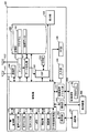
図1は、本実施の形態におけるネットワークシステム1000の構成を示す図である。図1を参照して、ネットワークシステム1000には、ホームネットワーク501.1,501.2,・・・,501.nが含まれる。以下においては、ホームネットワーク501.1,501.2,・・・,501.n(n:自然数)を総括的に、ホームネットワーク501ともいう。
<First Embodiment>
(System configuration)
FIG. 1 is a diagram illustrating a configuration of a
ホームネットワーク501は、たとえば、宅内に設けられたネットワークである。宅内とは、たとえば、ユーザの自宅内、会社内等である。ホームネットワーク501には、通信端末装置500と、映像表示装置600と、通信部50とが含まれる。
通信端末装置500は、携帯電話である。なお、通信端末装置500は、携帯電話に限定されることなく、通信機能を備え、携帯可能な装置であればどのような装置(たとえば、PDA(Personal Digital Assistance)、PC(Personal Computer))でもよい。
通信端末装置500は、電話網60と、無線によりデータ通信可能である。電話網60は、たとえば、携帯電話のための電話網である。なお、通信端末装置500は、電話網60とデータ通信をした場合、データ通信時に使用したデータ量に応じたパケット料金が発生する。
The
映像表示装置600は、テレビジョン受信機である。なお、映像表示装置600は、テレビジョン受信機の一例として、液晶テレビである。なお、映像表示装置600は、液晶テレビに限定されることなく、画像を表示可能な装置であればどのような装置であってもよい。映像表示装置600は、たとえば、プラズマテレビであってもよい。また、映像表示装置600は、画像を表示するための表示装置と、当該表示装置に表示させるための画像データを送信する画像データ送信装置とから構成される装置であってもよい。画像データ送信装置は、たとえば、PC、STB(Set Top Box)、HDD(Hard Disk Drive)レコーダ、DVD(Digital Versatile Disc)レコーダ等である。この場合、画像データ送信装置と表示装置の接続方法は特に規定されない。
The
通信端末装置500と、映像表示装置600とは、無線または有線でデータ通信を行なう。すなわち、通信端末装置500と、映像表示装置600とを含む映像表示システムが構成される。
通信部50は、通信端末装置500、映像表示装置600およびネットワーク70の各々と、データ通信を行なう機能を有する。ネットワーク70は、インターネットなどの外部のネットワークである。
The
通信部50は、無線LANの規格である、IEEE802.11gに基づく無線技術を利用して、複数の機器と同時にデータ通信を行なう機能を有する。なお、無線技術は、IEEE802.11gに基づく技術に限定されることはなく、その他の無線技術であってもよい。したがって、通信部50は、通信端末装置500、映像表示装置600およびネットワーク70の各々と、無線でデータ通信を行なうことが可能である。
The
また、通信部50は、さらに、イーサネット(登録商標)を利用した通信用インターフェースを有し、ホームネットワーク501内の装置がネットワーク70への接続要求を出した場合、機器が有するアドレスをネットワーク70におけるアドレスに変換するNAT(Network Address Translation)機能を含むルータ機能を持つ。
The
したがって、通信部50は、たとえば、LANケーブルを介して、通信端末装置500、映像表示装置600およびネットワーク70の各々とデータ通信を行なうことができる。すなわち、通信部50は、通信端末装置500、映像表示装置600およびネットワーク70の各々と、有線でデータ通信を行なうことが可能である。
Therefore, the
また、ネットワーク70は、電話網60と、無線または有線によりデータ通信可能である。したがって、通信端末装置500は、電話網60を介して、ネットワーク70とデータ通信可能である。
The
ネットワークシステム1000には、さらに、サービスサーバ800Aと、検索サーバ800Sと、Webサーバ800Wとが含まれる。
サービスサーバ800Aは、コンテンツおよび、コンテンツに関連する情報等を提供するサーバである。コンテンツは、たとえば、動画像、音楽データ等である。コンテンツが、たとえば、番組の動画像である場合、コンテンツに関連する情報とは、たとえば、番組情報である。サービスサーバ800Aは、PCである。なお、サービスサーバ800Aは、PCに限定されることなく、動画像等のコンテンツ、音楽データ等のコンテンツ、コンテンツに関連する情報等を提供する機能を有した装置であればどのような装置であってもよい。
The
サービスサーバ800Aは、現在の日時から、所定期間(たとえば、24時間)前の日時までの期間における、全てのチャンネルの全ての番組を録画し、番組を録画した録画データを記憶している。なお、サービスサーバ800Aは、現在の日時から、所定期間(たとえば、24時間)経過後の録画データを自動的に削除する。したがって、サービスサーバ800Aには、現在の日時から、所定期間前の日時までの期間における、全てのチャンネルの全ての番組の録画データが記憶されている。
The
また、サービスサーバ800Aは、放送される番組の録画データとは別に、装置からの配信要求に応じて配信する、映画などの映像コンテンツを記憶している。なお、サービスサーバ800Aは、録画データの配信要求があれば、録画データの配信要求を行なった装置へ、配信要求された録画データを、送信またはストリーミング配信する。
The
また、サービスサーバ800Aは、現在、放送中の番組およびこれから放送予定の動画像データを所定期間(たとえば、24時間)分予め記憶している。そして、現在、放送中の番組の動画像データの配信要求があれば、動画像データの配信要求を行なった装置へ、配信要求された動画像データをストリーミング配信する。
Further, the
検索サーバ800Sは、ネットワーク70に接続された端末装置から、検索情報としてのキーワードを受信すると、受信したキーワードに関連する情報のWebページのURL(Uniform Resource Locator)を検索するサーバである。検索サーバ800Sは、PCである。なお、検索サーバ800Sは、PCに限定されることなく、ネットワーク70に接続された端末装置からキーワードを受信した場合、受信したキーワードに関連する情報のWebページのURL(Uniform Resource Locator)を検索する機能を有する装置であればどのような装置であってもよい。
When a
Webサーバ800Wは、複数種類の情報の各々に対応する複数のWebページのデータを提供するサーバである。Webサーバ800Wは、たとえば、映画に関連する情報に対応する複数のWebページのデータを提供する。Webサーバ800Wは、PCである。なお、Webサーバ800Wは、PCに限定されることなく、複数種類の情報の各々に対応する複数のWebページのデータを提供する機能を有する装置であればどのような装置であってもよい。
サービスサーバ800A、検索サーバ800SおよびWebサーバ800Wの各々は、ネットワーク70と、無線または有線でデータ通信を行なう。
Each of
本実施の形態では、通信部50は、通信端末装置500、映像表示装置600およびネットワーク70の各々と、高速にデータ通信が可能であるとする。通信部50は、通信端末装置500、映像表示装置600およびネットワーク70の各々と、たとえば、最大で100Mbps(Mega bit per second)の速度でデータ通信が可能であるとする。
In the present embodiment, it is assumed that
また、ネットワーク70は、通信部50、電話網60、サービスサーバ800A、検索サーバ800SおよびWebサーバ800Wの各々と、高速にデータ通信が可能であるとする。ネットワーク70は、通信部50、電話網60、サービスサーバ800A、検索サーバ800SおよびWebサーバ800Wの各々と、たとえば、最大で100Mbpsの速度でデータ通信が可能であるとする。したがって、たとえば、映像表示装置600とネットワーク70とのデータ通信の最大速度は100Mbpsであるとする。また、たとえば、通信端末装置500とネットワーク70とのデータ通信の最大速度は100Mbpsであるとする。
In addition, it is assumed that the
なお、通信端末装置500と電話網60とのデータ通信の速度は、通信端末装置500とネットワーク70とのデータ通信の速度よりも遅いとする。通信端末装置500と電話網60とのデータ通信の最大速度は、たとえば、256kbpsであるとする。
It is assumed that the data communication speed between
また、通信端末装置500と映像表示装置600とのデータ通信の速度は、通信端末装置500と電話網60とのデータ通信の速度よりも、十分に速いとする。通信端末装置500と映像表示装置600とのデータ通信の最大速度は、たとえば、4Mbpsであるとする。
Further, it is assumed that the data communication speed between the
(通信端末装置)
次に、通信端末装置500について詳細に説明する。
(Communication terminal device)
Next, the
図2は、通信端末装置500の外観を正面から示した図である。図2を参照して、通信端末装置500は、表示部530と、音声出力部570と、LED576と、入力部540とを備える。
FIG. 2 is a diagram showing the external appearance of the
表示部530は、文字や画像等を表示する機能を有する。表示部530は、LCDパネル(Liquid Crystal Display Panel)を使用した装置である。なお、表示部530は、上記以外の表示方式のパネルを使用した装置であってもよい。
The
表示部530の解像度は、横480(ドット)×縦640(ドット)である。なお、表示部530の解像度は、横480(ドット)×縦640(ドット)に限定されることなく、他の解像度であってもよい。
The resolution of the
また、表示部530は、ユーザが、画面に直接触れることで、情報入力可能なタッチパネル機能を有する。表示部530は、ユーザが画面にタッチした位置情報を、後述する制御部510へ送信する。制御部510は、受信した位置情報に基づいて、所定の処理を行なう。
The
音声出力部570は、電話の音声を出力する機能を有する。音声出力部570には、音声を出力するスピーカが含まれる。音声出力部570は、後述する制御部510から受信した音声データに基づく音声をスピーカから出力する。
The
LED576は、通信端末装置500で行なわれる処理に応じて、光による報知を行なう。たとえば、LED576は、電話の着信があった場合、光を点滅させる。
The
入力部540は、ボタン群541を含む。ボタン群541は、方向ボタン541A,541B,541C,541Dと、決定ボタン541Eとを含む。方向ボタン541A,541B,541C,541Dは、ユーザによる短時間(たとえば、1秒未満)の押下操作(以下、短押操作ともいう)により、表示部530に画像が表示されている場合、画像内の移動させる対象となる物(たとえば、カーソル等)を上下左右に移動させるためのボタンである。
The
具体的には、短押操作があった、方向ボタン541A,541B,541C,541Dは、たとえば、カーソルを、それぞれ、上,下,左,右に移動させるためのボタンである。また、方向ボタン541A,541B,541C,541Dは、ユーザによる長時間(たとえば、一秒以上)の押下操作(以下、長押操作ともいう)により、たとえば画面をそれぞれ、上,下,左,右に画面スクロールすることも可能である。
Specifically, the
決定ボタン541Eは、短押操作により、たとえば、方向ボタン541A,541B,541C,541Dの短押操作により選択された項目等を決定するためのボタンである。
The
入力部540は、さらに、機能ボタン542A,542B,543A,543Bを含む。機能ボタン542A,542Bの各々は、短押操作により、たとえば、ユーザにより予め設定されたプログラム等を起動させるためのボタンである。
機能ボタン543Aは、電話をかけるためのボタンである。たとえば、機能ボタン543Aは、後述する数字ボタン群546の短押操作により電話番号を入力した後に、短押操作されることで、入力した電話番号の端末装置に電話をかける処理が行なわれる。また、機能ボタン543Aは、通信端末装置500に電話がかかってきた場合、短押操作により通話開始を行なうためのボタンである。機能ボタン543Bは、通信端末装置500が通話中である場合、短押操作により通話を終了させるためのボタンである。また、機能ボタン543Bは、ユーザによる長時間(たとえば、1秒以上)の押下操作(以下、長押操作ともいう)により、通信端末装置500の電源のオンとオフとの切替えを行なうためのボタンである。
The
入力部540は、さらに、数字ボタン群546を含む。数字ボタン群546は、12個の数字ボタンを含む。なお、数字ボタン群546に含まれる数字ボタンの数は、12個に限定されない。12個の数字ボタンの各々は、短押操作により、数字、文字または記号等を入力するためのボタンである。12個の数字ボタンの名称は、それぞれ、0ボタン,1ボタン,2ボタン,3ボタン,4ボタン,5ボタン,6ボタン,7ボタン,8ボタン,9ボタン,記号ボタン1、記号ボタン2という。
入力部540は、入力部540に含まれる複数のボタンのうち、短押操作または長押操作されたボタンに対応するボタン信号を、後述する制御部510へ送信する。すなわち、入力部540は、ユーザが通信端末装置500を操作するためのインターフェースである。以下においては、ユーザによる、入力部540の操作または表示部530に対するタッチ操作を、インターフェース操作Mともいう。
The
通信端末装置500は、さらに、音声入力部574と、生体情報取得部577とを備える。音声入力部574は、通話のときに、音声を入力する機能を有する。音声入力部574には、音声を入力するマイクが含まれる。音声入力部574は、マイクにより取得した音声を音声データに変換して、音声データを、通信端末装置500内の後述する制御部510へ送信する。
生体情報取得部577は、人間の生体情報を取得する機能を有する。本実施の形態では、生体情報は、人間の体の一部である指紋をデータ化した情報であるとする。この場合、生体情報は、指紋の画像データ、指紋の特徴部分を抽出したデータ等となる。なお、生体情報は、指紋をデータ化した情報に限定されることなく、静脈、網膜、虹彩、顔等をデータ化した情報であってもよい。また、生体情報は、人間が発した声に基づく声紋等であってもよい。
The biological
生体情報取得部577は、人間の体の一部が接触すると、接触した体の一部をデータ化した生体情報を、後述する制御部510へ送信する。
When a part of the human body comes into contact, the biological
携帯端末装置500は、さらに、記録媒体挿入部550Aを備える。記録媒体挿入部550Aは、携帯端末装置500に後述する記録媒体を挿入する部分である。
The portable
図3は、通信端末装置500の外観を背面から示した図である。図3を参照して、通信端末装置500は、さらに、音声出力部572と、撮像部578とを備える。音声出力部572は、後述する制御部510で行なわれる処理に対応した音声を出力する機能を有する。音声出力部572には、音声を出力するスピーカが含まれる。音声出力部572は、後述する制御部510から受信した音声データに基づく音声をスピーカから出力する。
FIG. 3 is a diagram showing the appearance of the
撮像部578は、撮像対象となる被写体を撮像する撮像処理を行なう機能を有する。撮像部578は、図示しない、撮像レンズ、受光部およびカラーフィルタ部とを含む。受光部は、入力された光を電気信号に変換する機能を有する。受光部は、複数の受光素子から構成される。受光素子は、たとえば、CCD(Charge Coupled Device)イメージセンサまたはCMOS(Complementary Metal Oxide Semiconductor)イメージセンサ等を使用した素子である。
The
カラーフィルタ部は、複数のカラーフィルタから構成される。カラーフィルタは、R、G、Bの各々に対応したフィルタである。複数のカラーフィルタは、複数の受光素子にそれぞれ対応して設けられる。 The color filter unit is composed of a plurality of color filters. The color filter is a filter corresponding to each of R, G, and B. The plurality of color filters are provided corresponding to the plurality of light receiving elements, respectively.
撮像処理では以下の処理が行なわれる。まず、撮像部578が、撮像対象となる被写体に反射されて撮像レンズに入射した光を、カラーフィルタ部を介して、受光部に入力させる。受光部は入力された光を電気信号に変換する。そして、撮像部578は、変換した電気信号をデジタルデータ(以下、撮像画像データともいう)に変換する。
The following processing is performed in the imaging processing. First, the
図4は、通信端末装置500の内部構成を示したブロック図である。なお、図4には、説明のために、記録媒体555も示している。記録媒体555には、後述するプログラム180が記録されている。すなわち、プログラム180は、媒体等に記録されてプログラム製品として流通される。また、記録媒体555もプログラム製品として流通される。
FIG. 4 is a block diagram showing an internal configuration of
図4を参照して、通信端末装置500は、さらに、制御部510と、一時記憶部522と、記憶部520とを備える。
Referring to FIG. 4,
記憶部520は、データを不揮発的に記憶する機能を有する。記憶部520は、制御部510によってデータアクセスされる。記憶部520は、電源を供給されなくてもデータを不揮発的に保持可能な媒体(たとえば、フラッシュメモリ)である。記憶部520には、プログラム180、後述する録画データ、その他の各種データ等が記憶されている。プログラム180は、後述する、リモコンプログラムを含む。
The
制御部510は、記憶部520に記憶されたプログラム180に従って、通信端末装置500内の各部に対する各種処理や、演算処理等を行なう機能を有する。制御部510は、CPU(Central Processing Unit)である。なお、制御部510は、CPUに限定されることなく、演算機能を有するその他の回路であってもよい。
一時記憶部522は、制御部510によってデータアクセスされ、一時的にデータを記憶するワークメモリとして使用される。一時記憶部522は、DRAM(Dynamic Random Access Memory)である。なお、一時記憶部522は、DRAMに限定されることなく、データを揮発的に記憶可能なその他の回路であってもよい。
通信端末装置500は、さらに、アンテナ502と、チューナ505と、データ処理部507とを備える。
アンテナ502は、チューナ505と接続されている。チューナ505は、制御部510により指示された周波数の放送信号を、アンテナ502を介して受信する。チューナ505は、ディジタル放送およびアナログ放送に基づく放送信号を受信する機能を有する。
The
放送信号は、画像データ、音声データ、テキストデータ、EPG(Electric Program Guide)データを含む。なお、放送信号が、ディジタル放送に基づく信号である場合、放送信号は、さらに、BML(Broadcast Markup Language)データ等が含まれる。EPGデータは、複数の番組情報を示すデータである。BMLデータは、画像データ、音声データおよびテキストデータの各々の配置位置や、動作などの制御を行なうためのデータである。チューナ505は、受信した放送信号を、データ処理部507へ送信する。
The broadcast signal includes image data, audio data, text data, and EPG (Electric Program Guide) data. When the broadcast signal is a signal based on digital broadcasting, the broadcast signal further includes BML (Broadcast Markup Language) data and the like. The EPG data is data indicating a plurality of program information. BML data is data for controlling the arrangement position and operation of each of image data, audio data, and text data. The tuner 505 transmits the received broadcast signal to the
データ処理部507は、受信した放送信号を復調し、復調データとする。受信した放送信号が、アナログ放送に基づく信号である場合、データ処理部507は、以下の処理を行なう。まず、データ処理部507は、復調データを、デコード処理し、画像データ、音声データを得るとともに、放送信号の垂直帰線区間(VBI:Vertical Blanking Interval)から、テキストデータ、EPGデータを得る。
The
そして、データ処理部507は、制御部510から、表示部530に画像を表示させるための表示指示を受信すると、画像データを、後述するVDP(Video Display Processor)532へ送信する。VDP532は、画像データを受信すると、表示部530に画像データに基づく画像(動画像または静止画像)を表示させる。
When the
また、データ処理部507は、制御部510から、録画処理を行なうための録画指示を受信すると、画像データおよび音声データを圧縮して、録画データとして、記憶部520に記憶させる。この場合の録画データを、以下においては、コンテンツともいう。録画データは、MPEG(Moving Picture Experts Group)4形式で圧縮されたデータである。なお、録画データは、MPEG4形式で圧縮されたデータに限定されることなく、他の形式で圧縮されたデータであってもよい。ここで、他の形式とは、たとえば、MPEG1、MPEG2、H.264等の形式である。
In addition, when the
また、受信した放送信号が、ディジタル放送に基づく信号である場合、データ処理部507は、以下の処理を行なう。まず、データ処理部507は、復調データを、ディジタル放送のプロトコルに基づいてデコード処理し、デコードデータにする。デコードデータには、画像データ、音声データ、テキストデータ、EPGデータ、BMLデータが含まれる。デコードデータに含まれる、画像データおよび音声データは、MPEG4形式で圧縮されたデータである。なお、デコードデータに含まれる、画像データおよび音声データは、MPEG4形式で圧縮されたデータに限定されることなく、他の形式で圧縮されたデータであってもよい。ここで、他の形式とは、たとえば、MPEG1、MPEG2、H.264等の形式である。
When the received broadcast signal is a signal based on digital broadcast, the
そして、データ処理部507は、制御部510から、表示部530に画像を表示させるための表示指示を受信すると、表示指示により指定されたチャンネルのデコードデータに含まれる画像データを、後述するVDP532へ送信する。VDP532は、画像データを受信すると、表示部530に画像データに基づく画像(動画像または静止画像)を表示させる。
When the
また、データ処理部507は、制御部510から、録画処理を行なうための録画指示を受信すると、録画指示により指定されたチャンネルのデコードデータを、録画データとして、記憶部520に記憶させる。この場合の録画データを、以下においては、コンテンツともいう。この場合、録画データには、画像データ、音声データ、テキストデータおよびBMLデータが含まれる。
Further, when receiving a recording instruction for performing a recording process from the
通信端末装置500は、さらに、VDP532と、VRAM(Video Random Access Memory)536とを備える。
VRAM536は、画像データを一時的に記憶する機能を有する。
制御部510は、記憶部520に記憶されたプログラム180に従って、VDP532に対し、描画指示を出す。描画指示とは、画像を生成し、当該画像を表示部530に表示させる指示である。
The
VDP532は表示部530と接続されている。VDP532は、制御部510からの描画指示に応じて、記憶部520内の後述するプログラム180からフォントデータ、図形データ等を読出し、VRAM536を利用して画像を生成する。そして、VDP532は、VRAM536に記憶された画像データを読出し、表示部530に、当該画像データに基づく画像を表示させる。
The
通信端末装置500は、さらに、入力部540と、記録媒体アクセス部550を備える。
制御部510は、入力部540に含まれる、前述した複数のボタンのうち、短押操作または長押操作があったボタンに対応するボタン信号を、入力部540から受信する。制御部510は、受信したボタン信号に応じた処理を行なう。
記録媒体アクセス部550は、記録媒体555が前述の記録媒体挿入部550Aから通信端末装置500に挿入(装着)されると、記録媒体555にデータアクセス可能となる。これにより、記録媒体アクセス部550は、プログラム180が記録された記録媒体555から、プログラム180を読出すことが可能となる。
The recording
記録媒体555に記憶されているプログラム180は、制御部510のインストール処理により、記録媒体アクセス部550により読み出され、制御部510が、プログラム180を、記憶部520に記憶させる。このインストール処理用プログラムは、予め、記憶部520に格納されており、インストール処理は、制御部510が、インストール処理用プログラムに基づいて行なう。
The
なお、記憶部520には、プログラム180がインストールされていなくてもよい。この場合、制御部510は、記録媒体アクセス部550を介して、記録媒体555に記憶されたプログラム180を読み出して、プログラム180に基づいた所定の処理を行なう。記録媒体555には、さらに、コンテンツデータ等も記録されている。コンテンツデータは、たとえば、音楽データ、動画像データ等である。
Note that the
記録媒体555は、SD(Secure Digital(登録商標))メモリーカードである。なお、記録媒体555は、SDメモリーカード(登録商標)に限定されることなく、データを不揮発的に記録可能なその他の媒体であってもよい。 The recording medium 555 is an SD (Secure Digital (registered trademark)) memory card. The recording medium 555 is not limited to the SD memory card (registered trademark), and may be another medium capable of recording data in a nonvolatile manner.
通信端末装置500は、さらに、通信部560と、通信部562とを備える。
通信部560は、制御部510とデータの送受信を行なう。また、通信部560は、映像表示装置600と有線または無線で、データの送受信を行なう機能を有する。
通信部560は、USB(Universal Serial Bus)2.0の規格に基づく、シリアル転送を行なう通信用インターフェースの機能を有する。なお、シリアル転送を行なう通信用インターフェースの規格は、USB2.0に限定されることなく他の規格であってもよい。
The
なお、通信部560は、パラレル転送を行なう通信用インターフェースの機能を有していてもよい。パラレル転送を行なう通信用インターフェースは、たとえば、セントロニクス準拠の規格に準拠したインターフェースである。また、通信部560は、IEEE1394またはSCSI規格に基づく通信用インターフェースの機能を有していてもよい。
Note that the
また、通信部560は、さらに、無線データ通信機能を有する。無線データ通信機能は、Bluetooth(登録商標)を使用して、無線でデータ通信を行なう機能を有する。なお、無線データ通信は、Bluetooth(登録商標)を使用した方式に限定されることなく、たとえば、赤外線等を使用した他の通信方式であってもよい。通信部560は、制御部510からの制御指示に応じて、映像表示装置600と無線でデータ通信を行なう。
通信部562は、制御部510と、データの送受信を行なう。通信部562は、無線LANの規格である、IEEE802.11gに基づく無線技術を利用してデータ通信を行なう機能を有する。なお、無線技術は、IEEE802.11gに基づく技術に限定されることはなく、その他の無線技術であってもよい。したがって、通信部562は、無線により、通信部50とデータ通信を行なうことができる。
また、通信部562は、さらに、イーサネット(登録商標)を利用した通信用インターフェースの機能を有する。したがって、通信部562は、たとえば、LANケーブルを介して、通信部50とデータ通信を行なうことができる。
The
通信端末装置500は、さらに、アンテナ564と、通信部566とを備える。
アンテナ564は、通信部566と接続されている。通信部566は、アンテナ564を利用して、無線通信信号を送受信する機能を有する。通信部566は、制御部510により指示された周波数の無線通信信号を、アンテナ564を介して受信する。無線通信信号は、音声データ、文字データおよび画像データ等を含む信号である。
The
通信部566は、アンテナ564を利用して、無線通信信号により、図示しない最寄の基地局と通信を行なう。最寄の基地局は、電話網60と通信を行なうことができる。したがって、通信部566は、アンテナ564を利用して、無線通信信号により、最寄の基地局を介して、電話網60と通信を行なう。通信部566は、無線通信信号を受信した場合、当該無線通信信号を復調し、復調した無線通信信号に基づくデータを、制御部510へ送信する。また、通信部566は、無線通信信号を送信する場合、制御部510からデータ(たとえば、音声データ)を受信し、当該データを、所定のプロトコルに基づいて、無線通信信号に変換する。そして、通信部566は、アンテナ564を利用して、変換した無線通信信号を、図示しない最寄の基地局を介して、電話網60へ送信する。
通信部566は、最寄の基地局と通信を行なうことで、基地局の位置を示す情報(以下、基地局位置情報ともいう)も取得可能である。通信部566は、制御部510からの制御指示に応じて、取得した基地局位置情報を、制御部510へ送信する。制御部510は、受信した基地局位置情報に基づいて、通信端末装置500の位置を大まかに把握することができる。
The
また、通信部566は、GPS(Global Positioning System)機能を有する。GPS機能とは、人口衛星と通信して、通信端末装置500の位置(緯度、経度、高度等に基づく位置)の情報(以下、GPS位置情報ともいう)を取得する機能である。通信部566は、制御部510からの制御指示に応じて、GPS位置情報を取得し、制御部510へ送信する。
The
携帯端末装置500は、制御部510および通信部566の処理により、電話網60を介して、ネットワーク70からプログラムのダウンロード処理を行ない、記憶部520に格納することもできる。この場合、当該ダウンロードしたプログラムは、プログラム180である。
The portable
制御部510は、ネットワーク70からダウンロードしたプログラム(プログラム180)に従って、所定の処理を行なう。このダウンロード用プログラムは、予め、記憶部520に格納されており、ダウンロード処理は、制御部510が、ダウンロード用プログラムに基づいて行なう。
制御部510は、前述した音声出力部570,572、音声入力部574とデータ通信する。
制御部510が、音声データを音声出力部570へ送信すると、音声出力部570は、制御部510から受信した音声データに基づく音声をスピーカから出力する。制御部510が、音声データを音声出力部572へ送信すると、音声出力部572は、制御部510から受信した音声データに基づく音声をスピーカから出力する。
When
ユーザが音声入力部574に含まれるマイクに対して音声を発すると、音声入力部574は、マイクにより取得した音声を音声データに変換して、音声データを、制御部510へ送信する。
When the user utters voice to the microphone included in the
制御部510は、前述したLED576、撮像部578および生体情報取得部577の各々とデータ通信する。LED576は、制御部510からの制御指示に基づいて、光を発する。
撮像部578は、制御部510からの制御指示に基づいて、前述の撮像処理を行ない、撮像画像データを制御部510へ送信する。制御部510は、撮像画像データを受信すると、撮像画像データを、一時記憶部522、記憶部520および記録媒体555のいずれかに記憶させる。
The
生体情報取得部577は、生体情報を取得すると、取得した生体情報(たとえば、指紋情報)を、制御部510へ送信する。
When the biometric
通信端末装置500は、さらに、振動部579を備える。振動部579は、制御部510からの制御指示に基づいて、振動部579自身が振動することにより、通信端末装置500を振動させる機能を有する。振動部579は、たとえば、電話の着信、電子メールの受信時に、制御部510からの制御指示に基づいて、通信端末装置500を振動させる。
通信端末装置500は、さらに、RFID(Radio Frequency Identification)580を備える。RFID580は、たとえば、FeliCa(登録商標)などのセキュリティ機能をもったRFIDに基づく集積回路で、非接触で図示しない読み取り端末と通信を行う。また、RFID580は、制御部510からの制御指示に基づいて、端末IDなどのデータを出力する。
The
(映像表示装置)
次に、映像表示装置600について詳細に説明する。
(Video display device)
Next, the
図5は、映像表示装置600の内部構成を示したブロック図である。なお、図5には、説明のために、記録媒体555Aも示している。記録媒体555Aには、後述するプログラム180Aが記録されている。すなわち、プログラム180Aは、媒体等に記録されてプログラム製品として流通される。また、記録媒体555Aもプログラム製品として流通される。
FIG. 5 is a block diagram showing an internal configuration of the
図5を参照して、映像表示装置600は、表示部630と、音声出力部670とを備える。表示部630は、文字や画像等を表示する機能を有する。表示部630は、LCDパネル(Liquid Crystal Display Panel)を使用した装置である。なお、表示部530は、上記以外の表示方式のパネルを使用した装置であってもよい。
Referring to FIG. 5,
表示部630が表示可能な画像のサイズは、表示部530が表示可能な画像のサイズより大きい。また、表示部630の解像度は、表示部530の解像度より大きい。たとえば、表示部630の解像度は、横1366(ドット)×縦768(ドット)の解像度である。なお、表示部630の解像度は、横1366(ドット)×縦768(ドット)に限定されることなく、他の解像度であってもよい。
The size of the image that can be displayed by the
音声出力部670は、映像表示装置600の外部に設けられる。音声出力部670は、後述する制御部610で行なわれる処理に対応した音声を出力する機能を有する。音声出力部670には、音声を出力するスピーカが含まれる。音声出力部670は、後述する制御部610から受信した音声データに基づく音声をスピーカから出力する。
The
映像表示装置600は、さらに、制御部610と、一時記憶部622と、記憶部620とを備える。
The
記憶部620は、データを不揮発的に記憶する機能を有する。記憶部620は、制御部610によってデータアクセスされる。記憶部620は、大容量のデータを記憶可能なハードディスクである。なお、記憶部620は、ハードディスクに限定されることなく、電源を供給されなくてもデータを不揮発的に保持可能な媒体(たとえば、フラッシュメモリ)であればよい。記憶部620には、プログラム180A、後述する録画データ、映像表示装置600を識別するための装置ID、その他の各種データ等が記憶されている。
The
制御部610は、記憶部620に記憶されたプログラム180Aに従って、映像表示装置600内の各部に対する各種処理や、演算処理等を行なう機能を有する。制御部610は、前述の制御部510と同様なものであるので詳細な説明は繰り返さない。
一時記憶部622は、制御部610によってデータアクセスされ、一時的にデータを記憶するワークメモリとして使用される。一時記憶部622は、前述の一時記憶部522と同様なものであるので詳細な説明は繰り返さない。
The
映像表示装置600は、さらに、アンテナ602と、チューナ605と、データ処理部607とを備える。
The
アンテナ602は、チューナ605と接続されている。チューナ605は、制御部610により指示された周波数の放送信号を、アンテナ602を介して受信する。チューナ605は、ディジタル放送およびアナログ放送に基づく放送信号を受信する機能を有する。
The
放送信号は、画像データ、音声データ、テキストデータ、EPGデータを含む。なお、放送信号が、ディジタル放送に基づく信号である場合、放送信号は、さらに、前述したBMLデータ等が含まれる。チューナ605は、受信した放送信号を、データ処理部607へ送信する。
The broadcast signal includes image data, audio data, text data, and EPG data. When the broadcast signal is a signal based on digital broadcasting, the broadcast signal further includes the BML data described above. The tuner 605 transmits the received broadcast signal to the
データ処理部607は、受信した放送信号を復調し、復調データとする。受信した放送信号が、アナログ放送に基づく信号である場合、データ処理部607は、以下の処理を行なう。まず、データ処理部607は、復調データを、デコード処理し、画像データおよび音声データを取得するとともに、放送信号の垂直帰線区間から、テキストデータ、EPGデータを取得する。
The
そして、データ処理部607は、制御部610から、表示部630に画像を表示させるための表示指示を受信すると、画像データを、後述するVDP632へ送信する。VDP632は、画像データを受信すると、表示部630に画像データに基づく画像(動画像または静止画像)を表示させる。
When the
また、データ処理部607は、制御部610から、録画処理を行なうための録画指示を受信すると、画像データおよび音声データを圧縮して、録画データとして、記憶部620に記憶させる。録画データは、MPEG2形式で圧縮されたデータである。なお、録画データは、MPEG2形式で圧縮されたデータに限定されることなく、他の形式で圧縮されたデータであってもよい。ここで、他の形式とは、たとえば、H.264等の形式である。
In addition, when the
また、受信した放送信号が、ディジタル放送に基づく信号である場合、データ処理部607は、以下の処理を行なう。まず、データ処理部607は、復調データを、ディジタル放送の規格に基づいてデコード処理し、デコードデータにする。デコードデータには、画像データ、音声データ、テキストデータ、EPGデータ、BMLデータが含まれる。デコードデータに含まれる、画像データおよび音声データは、MPEG2形式で圧縮されたデータである。なお、デコードデータに含まれる、画像データおよび音声データは、MPEG2形式で圧縮されたデータに限定されることなく、他の形式で圧縮されたデータであってもよい。ここで、他の形式とは、たとえば、H.264等の形式である。
When the received broadcast signal is a signal based on digital broadcast, the
そして、データ処理部607は、制御部610から、表示部630に画像データを表示させるための表示指示を受信すると、表示指示により指定されたチャンネルのデコードデータに含まれる画像データを、後述するVDP632へ送信する。VDP632は、画像データを受信すると、表示部630に画像データに基づく画像(動画像または静止画像)を表示させる。
When the
以下においては、チューナ605が受信した放送信号に基づく画像であって、かつ、表示部630に表示される画像を、TV画像ともいう。なお、映像表示装置600を操作するための後述するリモコン300に設けられる、“1”〜“12”の数字ボタンの押下操作で、直接、選局可能なTV画像のチャンネルの種類の数は、最大で12個であるとする。当然のことながら、リモコン300に設けられる数字ボタンの数が多ければ多いほど、直接、選局可能なTV画像のチャンネルの種類の数は多くなる。
Hereinafter, an image based on a broadcast signal received by the tuner 605 and displayed on the
リモコン300の“1”〜“12”の数字ボタンには、それぞれ、“1”〜“12”のリモコンチャンネル番号が設定される。たとえば、“3”の数字ボタンには、リモコンチャンネル番号“3”が設定される。また、1つのリモコンチャンネル番号には、1つのTV画像のチャンネルを登録可能である。たとえば、リモコンチャンネル番号“1”に対し、TV画像のチャンネル番号“8”が登録されているとする。この場合、リモコン300の“1”の数字ボタンが、ユーザにより押下処理されることにより、リモコン300から、チャンネル番号“8”のTV画像を選局するためのリモコン信号が、映像表示装置600へ送信される。
Remote control channel numbers “1” to “12” are set in the numeric buttons “1” to “12” of the
なお、映像表示装置600は、複数種類のTV画像を同時に、表示部630に表示する機能を有する。また、映像表示装置600は、TV画像と、他の種類の画像とを同時に、表示部630に表示する機能を有する。
Note that the
また、データ処理部607は、制御部610から、録画処理を行なうための録画指示を受信すると、録画指示により指定されたチャンネルのデコードデータを、録画データとして、記憶部620に記憶させる。この場合の録画データを、以下においては、コンテンツともいう。この場合、録画データには、画像データ、音声データ、テキストデータおよびBMLデータが含まれる。
In addition, when the
映像表示装置600は、さらに、VDP632と、VRAM636とを備える。
VRAM636は、画像データを一時的に記憶する機能を有する。
The
The
制御部610は、記憶部620に記憶されたプログラム180Aに従って、VDP632に対し、描画指示を出す。描画指示とは、画像を生成し、当該画像を表示部630に表示させる指示である。
The
VDP632は表示部630と接続されている。VDP632は、制御部610からの描画指示に応じて、記憶部620内の後述するプログラム180Aからフォントデータ、図形データ等を読出し、VRAM636を利用して画像を生成する。そして、VDP632は、VRAM636に記憶された画像データを読出し、表示部630に、当該画像データに基づく画像を表示させる。
The
映像表示装置600は、さらに、入力部640と、記録媒体アクセス部650とを備える。
The
入力部640は、図示されない複数のボタンを含む。複数のボタンは、映像表示装置600の外部に設けられている。複数のボタンのうち、いずれかのボタンがユーザにより押下操作されると、入力部640は、押下操作されたボタンに対応するボタン信号を、制御部610へ送信する。制御部610は、受信したボタン信号に基づいて、所定の処理を行なう。以下においては、ユーザによる、入力部640のボタン操作を、インターフェース操作Tともいう。
記録媒体アクセス部650は、プログラム180Aが記録された記録媒体555Aから、プログラム180Aを読出す機能を有する。記録媒体555Aに記憶されているプログラム180Aは、制御部610のインストール処理により、記録媒体アクセス部650により読み出され、制御部610が、プログラム180Aを、記憶部620に記憶させる。このインストール処理用プログラムは、予め、記憶部620に格納されており、インストール処理は、制御部610が、インストール処理用プログラムに基づいて行なう。
The recording
なお、記憶部620には、プログラム180Aがインストールされていなくてもよい。この場合、制御部610は、記録媒体アクセス部650を介して、記録媒体555Aに記憶されたプログラム180Aを読み出して、プログラム180Aに基づいた所定の処理を行なう。記録媒体555Aには、さらに、コンテンツデータ等も記録されている。コンテンツデータは、たとえば、音楽データ、動画像データ等である。
Note that the
記録媒体555Aは、SDメモリーカード(登録商標)である。なお、記録媒体555は、SDメモリーカード(登録商標)に限定されることなく、データを不揮発的に記録可能なその他の媒体、たとえば、Blu-ray Disc(登録商標)、HD−DVD(High-Definition Digital Versatile Disc)(登録商標)、DVD−ROM(Digital Versatile Disk Read Only Memory)、CD−ROM(Compact Disk Read Only Memory)、等であってもよい。
The
映像表示装置600は、さらに、通信部660と、通信部662とを備える。
通信部660は、制御部610とデータの送受信を行なう。また、通信部660は、通信端末装置500と有線または無線で、データの送受信を行なう機能を有する。なお、通信部660は、前述の通信部560と同様な構成および機能を有するので詳細な説明は繰り返さない。
通信部662は、制御部610と、データの送受信を行なう。通信部662は、前述の通信部562と同様な構成および機能を有するので詳細な説明は繰り返さない。したがって、通信部662は、無線により、通信部50とデータ通信を行なうことができる。また、通信部662は、たとえば、LANケーブルを介して、通信部50とデータ通信を行なうことができる。
したがって、本実施の形態における映像表示装置600は、ネットワーク70から、通信部50および通信部662を介して、プログラムのダウンロード処理を行ない、記憶部620に格納することもできる。この場合、当該ダウンロードしたプログラムは、プログラム180Aである。
Therefore,
制御部610は、ネットワーク70からダウンロードしたプログラム(プログラム180A)に従って、所定の処理を行なう。このダウンロード用プログラムは、予め、記憶部620に格納されており、ダウンロード処理は、制御部610が、ダウンロード用プログラムに基づいて行なう。
映像表示装置600は、さらに、リモコン信号受信部680を備える。リモコン信号受信部680は、リモコン(リモートコントローラー)300から出力される、映像表示装置600を操作するためのリモコン信号を受信する機能を有する。リモコン信号受信部680は、受信したリモコン信号を制御部610へ送信する。制御部610は、受信したリモコン信号に応じて、対応する処理を行なう。なお、リモコン300には、前述したように、TV画像を選局するための“1”〜“12”の数字ボタンが設けられる。以下においては、ユーザによる、リモコン300の操作も、インターフェース操作Tともいう。
なお、前述した通信端末装置500がリモコン300の機能を有することも想定でき、通信端末装置500、リモコン300は、2つが存在する場合、および一方のみしか存在しない場合なども想定できる。
In addition, it can be assumed that the above-described
制御部610は、前述した音声出力部670とデータ通信する。制御部610が、音声データを音声出力部670へ送信すると、音声出力部670は、制御部610から受信した音声データに基づく音声をスピーカから出力する。
The
(サービスサーバ、検索サーバおよびWebサーバ)
図6は、サービスサーバ800Aの内部構成を示したブロック図である。図6を参照して、サービスサーバ800Aは、表示部830と、制御部810と、一時記憶部822と、記憶部820とを備える。
(Service server, search server and Web server)
FIG. 6 is a block diagram showing the internal configuration of the
表示部830は、文字や画像等を表示する機能を有する。表示部830は、前述の表示部630と同様なものであるので詳細な説明は繰り返さない。
The
記憶部820は、データを不揮発的に記憶する機能を有する。記憶部820は、制御部810によってデータアクセスされる。記憶部820は、大容量のデータを記憶可能なハードディスクである。なお、記憶部820は、ハードディスクに限定されることなく、電源を供給されなくてもデータを不揮発的に保持可能な媒体(たとえば、フラッシュメモリ)であればよい。記憶部820には、プログラム180B、録画データ、コンテンツデータ、その他の各種データ等が記憶されている。
The
制御部810は、記憶部820に記憶されたプログラム180Bに従って、サービスサーバ800A内の各部に対する各種処理や、演算処理等を行なう機能を有する。制御部810は、前述の制御部510と同様なものであるので詳細な説明は繰り返さない。
一時記憶部822は、制御部810によってデータアクセスされ、一時的にデータを記憶するワークメモリとして使用される。一時記憶部822は、前述の一時記憶部522と同様なものであるので詳細な説明は繰り返さない。
The
サービスサーバ800Aは、さらに、VDP832と、VRAM836とを備える。
VRAM836は、画像データを一時的に記憶する機能を有する。
The
制御部810は、記憶部820に記憶されたプログラム180Bに従って、VDP832に対し、描画指示を出す。描画指示とは、画像を生成し、当該画像を表示部830に表示させる指示である。
The
VDP832は表示部830と接続されている。VDP832は、制御部810からの描画指示に応じて、記憶部520内の後述するプログラム180Bからフォントデータ、図形データ等を読出し、VRAM836を利用して画像を生成する。そして、VDP832は、VRAM836に記憶された画像データを読出し、表示部830に、当該画像データに基づく画像を表示させる。
The
サービスサーバ800Aは、さらに、入力部840を備える。
入力部840には、マウス842と、キーボード844とが接続されている。ユーザは、マウス842またはキーボード844を利用して、サービスサーバ800Aに指示を与える。マウス842またはキーボード844からの入力指示は、入力部840を介して制御部810へ送信される。制御部810は、入力部840からの入力指示に基づいて所定の処理を行なう。
A
サービスサーバ800Aは、さらに、通信部860と、通信部862とを備える。
通信部860は、制御部810とデータの送受信を行なう。また、通信部860は、図示しない他の装置と有線または無線で、データの送受信を行なう機能を有する。なお、通信部860は、前述の通信部560と同様な構成および機能を有するので詳細な説明は繰り返さない。
The
The
通信部862は、制御部810と、データの送受信を行なう。通信部862は、前述の通信部562と同様な構成および機能を有するので詳細な説明は繰り返さない。したがって、通信部862は、無線により、ネットワーク70とデータ通信を行なうことができる。また、通信部862は、たとえば、LANケーブルを介して、ネットワーク70とデータ通信を行なうことができる。
なお、検索サーバ800SおよびWebサーバ800Wの各々も、前述したサービスサーバ800Aと同様な構成を有するので詳細な説明は繰り返さない。
Each of
(リモコン)
次に、通信端末装置500を、映像表示装置600を操作するためのリモコン(以下、表示装置リモコンともいう)として使用するための処理について説明する。インターフェース操作Mにより、制御部510がプログラム180のリモコンプログラムを実行すると、通信端末装置500を、表示装置リモコンとして使用することが可能となる。この場合、表示部530には、以下のリモコン画像MG100が表示される。
(Remote controller)
Next, processing for using
図7は、一例としてのリモコン画像MG100を示す図である。図7を参照して、リモコン画像MG100には、ボタン画像MBG110,MBG120,MBG130が配置される。 FIG. 7 is a diagram showing a remote control image MG100 as an example. Referring to FIG. 7, button images MBG110, MBG120, and MBG130 are arranged in remote control image MG100.
ボタン画像MBG110,MBG120,MBG130の各々は、インターフェース操作Mにより、押下処理されることで、制御部510が、後述の対応するリモコン信号を、通信部560を利用して、映像表示装置600へ送信するためのボタン画像である。
Each of the button images MBG110, MBG120, and MBG130 is pressed by the interface operation M, so that the
ボタン画像MBG110は、インターフェース操作Mにより、押下処理されることで、電源リモコン信号を、映像表示装置600へ送信するためのボタン画像である。ここで、映像表示装置600は、待機モードを有する。待機モードとは、表示部630に画像を表示させるための電源がオフであるために、表示部630が画像を表示できない状態であって、主電源がオフでない状態である。すなわち、待機モードとは、表示部630に画像が表示されていない状態であって、主電源がオフでない状態である。以下においては、表示部630に画像を表示させるための電源を画像表示電源ともいう。
The button image MBG110 is a button image for transmitting a power supply remote control signal to the
したがって、映像表示装置600が待機モードの場合、電源リモコン信号を受信することにより、画像表示電源がオンされることにより、表示部630に画像を表示させることができる。なお、以下においては、画像表示電源がオンの状態の映像表示装置600を通常モードともいう。すなわち、電源リモコン信号は、映像表示装置600において、待機モードと、通常モードとを切替えるためのリモコン信号である。
Therefore, when the
ボタン画像MBG120は、インターフェース操作Mにより、押下処理されることで、番組表表示リモコン信号を、映像表示装置600へ送信するためのボタン画像である。番組表表示リモコン信号は、映像表示装置600の表示部630に、後述する番組表画像を表示させるためのリモコン信号である。
The
ボタン画像MBG130は、インターフェース操作Mにより、押下処理されることで、メニュー表示リモコン信号を、映像表示装置600へ送信するためのボタン画像である。メニュー表示リモコン信号は、映像表示装置600の表示部630に、後述するメニュー画像を表示させるためのリモコン信号である。
The button image MBG 130 is a button image for transmitting a menu display remote control signal to the
リモコン画像MG100には、さらに、ボタン画像MBG142,MBG144,MBG152,MBG154が配置される。ボタン画像MBG142,MBG144,MBG152,MBG154の各々は、インターフェース操作Mにより、押下処理されることで、制御部510が、後述の対応するリモコン信号を、通信部560を利用して、映像表示装置600へ送信するためのボタン画像である。
In remote control image MG100, button images MBG142, MBG144, MBG152, and MBG154 are further arranged. Each of the button images MBG142, MBG144, MBG152, and MBG154 is pressed by the interface operation M, so that the
ボタン画像MBG142は、インターフェース操作Mにより、押下処理されることで、音量アップリモコン信号を、映像表示装置600へ送信するためのボタン画像である。音量アップリモコン信号は、映像表示装置600の音声出力部670から出力される音声を大きくさせるためのリモコン信号である。ボタン画像MBG144は、インターフェース操作Mにより、押下処理されることで、音量ダウンリモコン信号を、映像表示装置600へ送信するためのボタン画像である。音量ダウンリモコン信号は、映像表示装置600の音声出力部670から出力される音声を小さくさせるためのリモコン信号である。
The button image MBG 142 is a button image for transmitting a volume up remote control signal to the
ボタン画像MBG152は、インターフェース操作Mにより、押下処理されることで、チャンネルプラスリモコン信号を、映像表示装置600へ送信するためのボタン画像である。チャンネルプラスリモコン信号は、映像表示装置600の表示部630にTV画像が表示されている場合に、前述のリモコンチャンネル番号を1インクリメントさせるためのリモコン信号である。なお、リモコンチャンネル番号が“12”の場合に、上記の1インクリメントされる処理が行われた場合、リモコンチャンネル番号は、“1”になる。なお、チャンネルプラスリモコン信号は、TV画像のチャンネル番号を、1インクリメントさせるためのリモコン信号であってもよい。
The button image MBG 152 is a button image for transmitting a channel plus remote control signal to the
ボタン画像MBG154は、インターフェース操作Mにより、押下処理されることで、チャンネルマイナスリモコン信号を、映像表示装置600へ送信するためのボタン画像である。チャンネルマイナスリモコン信号は、映像表示装置600の表示部630にTV画像が表示されている場合に、前述のリモコンチャンネル番号を1デクリメントさせるためのリモコン信号である。なお、リモコンチャンネル番号が“1”の場合に、上記の1デクリメントされる処理が行われた場合、リモコンチャンネル番号は、“12”になる。なお、チャンネルマイナスリモコン信号は、TV画像のチャンネル番号を、1デクリメントさせるためのリモコン信号であってもよい。
The button image MBG154 is a button image for transmitting a channel minus remote control signal to the
リモコン画像MG100には、さらに、ボタン画像MBG180が配置される。ボタン画像MBG180の各々は、インターフェース操作Mにより、押下処理されることで、制御部510が、後述の対応するリモコン信号を、通信部560を利用して、映像表示装置600へ送信するためのボタン画像である。
A remote control image MG100 further includes a button image MBG180. Each of the
以下においては、通信端末装置500が、映像表示装置600へリモコン信号を送信することで映像表示装置600を操作可能な場合における、通信端末装置500の動作モードを、リモコンモードともいう。
Hereinafter, the operation mode of the
なお、リモコンモードの通信端末装置500において、数字ボタン群546に含まれる12個の数字ボタンのいずれかが短押操作された場合、制御部510は、押下された数字ボタンに対応するリモコン信号を出力する。
In the remote control mode
(事前登録)
次に、映像表示装置600が、サービスサイトに登録する処理(以下、登録処理ともいう)について説明する。サービスサイトは、サービスを提供するWebサイトある。ここで、サービスサイトが提供するサービスは、たとえば、コンテンツの配信である。配信されるコンテンツは、たとえば、動画像データ、ニュース等の情報である。ここで、サービスサイトは、サービスサーバ800Aが提供するサイトであるとする。サービスサイトが提供するデータは、サービスサーバ800Aの記憶部820に記憶されている。
(Pre-registration)
Next, a process (hereinafter also referred to as a registration process) in which the
映像表示装置600は、サービスサイトに登録することで、サービスサイトから、様々なサービスを享受することが可能となる。サービスサイトは、サービスサーバ800Aが提供するWebサイトであるので、サービスサーバ800Aが提供するサービスサイトに登録することは、サービスサーバ800Aに対し登録することになる。
The
前述のプログラム180Aには、さらに、サービスサイトにアクセスするためのWebブラウザを表示部630に表示するためのWebブラウザプログラムが含まれる。以下の登録処理は、リモコンモードの通信端末装置500におけるインターフェース操作Mにより、制御部610がプログラム180AのWebブラウザプログラムを実行した状態で行なわれるとする。これにより、表示部630には、以下のWebブラウザ画像G200が表示されているとする。
The above-described
図8は、一例としてのWebブラウザ画像G200を示す図である。図8を参照して、Webブラウザ画像G200には、URL表示画像G210と、Webページ画像G220と、ボタン画像BG281とが配置される。 FIG. 8 is a diagram showing a web browser image G200 as an example. Referring to FIG. 8, URL display image G210, Web page image G220, and button image BG281 are arranged in Web browser image G200.
URL表示画像G210には、リモコンモードの通信端末装置500におけるインターフェース操作Mにより、サービスサイトに登録するためのWebページのURLが入力されている。
In the URL display image G210, the URL of the Web page for registration in the service site is input by the interface operation M in the
Webページ画像G220は、サービスサーバ800Aの提供するサービスサイト内にあるWebページである。Webページ画像G220は、サービスサイトに登録するためのWebページを表示した画像である。Webページ画像G220には、リモコンモードの通信端末装置500におけるインターフェース操作Mにより、サービスサイトの登録に必要な情報が入力されている。サービスサイトの登録に必要な情報は、たとえば、名前、メールアドレス、性別等の情報である。
Web page image G220 is a Web page in a service site provided by
なお、嗜好キーワードとは、ユーザの嗜好に応じたキーワードである。すなわち、嗜好キーワードは、嗜好情報である。なお、嗜好キーワードの入力は任意であるとする。Webページ画像MG220では、嗜好キーワードの一例として、「サッカー」、「野球」、「お笑い」というキーワードが入力されている。なお、嗜好キーワードは、3つに限定されることはない。 The preference keyword is a keyword according to the user's preference. That is, the preference keyword is preference information. It is assumed that the preference keyword can be input arbitrarily. In Web page image MG220, keywords “soccer”, “baseball”, and “comed” are input as examples of preference keywords. Note that the preference keywords are not limited to three.
Webページ画像G220には、ボタン画像BG285が配置されている。ボタン画像BG285は、押下処理されることにより、サービスサイトに登録する処理を許可するためのボタン画像である。ボタン画像BG285の押下処理は、リモコンモードの通信端末装置500において、ボタン画像BG285を押下処理するためのインターフェース操作Mがあった場合に行なわれる。
A button image BG285 is arranged on the Web page image G220. The button image BG285 is a button image for permitting processing to be registered in the service site by being pressed. The pressing process of the button image BG285 is performed when there is an interface operation M for pressing the button image BG285 in the
ボタン画像BG281は、押下処理されることにより、Webブラウザ画像G200内に、現在、表示されているWebページ画像G220の前に、Webブラウザ画像G200に表示されていたWebページ画像(以下、旧Webページ画像ともいう)が存在する場合、旧Webページ画像をWebブラウザ画像G200に表示させるためのボタン画像である。ボタン画像BG281の押下処理は、リモコンモードの通信端末装置500において、ボタン画像BG281を押下処理するためのインターフェース操作Mがあった場合に行なわれる。
When the button image BG281 is pressed, the web page image (hereinafter referred to as the old web page) displayed in the web browser image G200 before the web page image G220 currently displayed in the web browser image G200 is pressed. In the case where there is a page image), this is a button image for displaying the old Web page image on the Web browser image G200. The pressing process of the button image BG281 is performed when there is an interface operation M for pressing the button image BG281 in the
図9は、登録処理のフローチャートである。図9では、映像表示装置600およびサービスサーバ800Aの各々において行なわれる処理を示す。図9を参照して、映像表示装置600では、まず、ステップS110の処理が行なわれる。
FIG. 9 is a flowchart of the registration process. FIG. 9 shows processing performed in each of
ステップS110では、制御部610が、登録許可操作があるか否かを判定する。登録許可操作とは、表示部630にWebブラウザ画像G200が表示されている状態で、ボタン画像BG285を押下処理する操作である。リモコンモードの通信端末装置500において、ボタン画像BG285を押下処理するためのインターフェース操作Mがあった場合、ボタン画像BG285を押下処理するためのリモコン信号が映像表示装置600へ送信され、制御部610は、当該リモコン信号を受信する。この場合、制御部610は、ボタン画像BG285を押下処理し、登録許可操作があったと判定する。
In step S110,
ステップS110において、YESならば、ステップS111に進む。一方、ステップS110において、NOならば、再度、ステップS110の処理が行なわれる。 If YES in step S110, the process proceeds to step S111. On the other hand, if NO at step S110, the process at step S110 is performed again.
ステップS111では、制御部610が、Webブラウザ画像G200に入力された情報を、ユーザデータとして、記憶部620に記憶させる。これにより、記憶部620には、以下のユーザデータTD50が記憶されるとする。そして、ステップS111の処理は終了する。
In step S111, the
図10は、一例としてのユーザデータTD50を示す図である。図10を参照して、ユーザデータTD50において、「装置ID」とは、装置を識別するための情報である。ユーザデータTD50に示される「装置ID」は、映像表示装置600を操作している通信端末装置500の装置IDである。通信端末装置500の装置IDは、たとえば、電話番号であるとする。なお、装置IDは、電話番号以外のものであってもよい。
FIG. 10 is a diagram showing user data TD50 as an example. Referring to FIG. 10, in user data TD50, “device ID” is information for identifying a device. The “device ID” indicated in the user data TD50 is the device ID of the
再び、図9を参照して、ステップS111の処理の後、ステップS112に進む。
ステップS112では、制御部610が、登録データを、サービスサーバ800Aへ送信する。登録データは、図10のユーザデータTD50と、登録する映像表示装置600の装置IDとを含むデータである。ここで、映像表示装置600の装置IDは、一例として、“11TA”であるとする。その後、ステップS112の処理は終了する。
Referring to FIG. 9 again, after the process of step S111, the process proceeds to step S112.
In step S112,
サービスサーバ800Aでは、まず、ステップS120の処理が行なわれる。
ステップS120では、制御部810が、登録データを受信したか否かを判定する。ステップS120において、YESならば、ステップS121に進む。一方、ステップS120において、NOならば、再度、ステップS120の処理が行なわれる。ここでは、ユーザデータTD50と、装置ID“11TA”とを含む登録データを受信したとして、ステップS121に進む。
In
In step S120,
ステップS121では、制御部810が、受信した登録データを、記憶部820に記憶させる。この処理により、記憶部820には、ユーザデータTD50と、装置ID“11TA”とを含む登録データが記憶されるとする。そして、ステップS122に進む。
In step S <b> 121, the
ステップS122では、制御部810が、ユーザ識別情報を、映像表示装置600へ送信する。ユーザ識別情報は、映像表示装置600を特定するための識別情報である。ユーザ識別情報は、たとえば、クッキーである。ステップS122の処理が終了すると、再度、ステップS120の処理が行なわれる。
In step S122,
映像表示装置600では、ステップS112の処理が終了すると、ステップS114に進む。
In the
ステップS114では、制御部610が、サービスサーバ800Aから送信されたユーザ識別情報を受信する。その後、ステップS116に進む。
In step S114,
ステップS116では、制御部610が、受信したユーザ識別情報を、登録したサービスサイトのURLに対応づけて記憶部620に記憶させる。以上により、映像表示装置600での処理は終了する。
In step S116,
映像表示装置600が、複数種類のサービスサイトに対し、前述した登録処理を行なうことで、記憶部620には、以下のユーザ識別情報登録テーブルD100が記憶される。
When the
図11は、一例としてユーザ識別情報登録テーブルD100を示す図である。図11を参照して、ユーザ識別情報登録テーブルD100は、複数のユーザ識別情報登録データから構成される。「番号」とは、複数のユーザ識別情報登録データの各々を特定するための番号である。「サイト名」とは、登録したサービスサイトの名称である。「URL」とは、登録したサービスサイトのURLである。「ユーザ識別情報」とは、登録したサービスサイトから受信したユーザ識別情報(たとえば、クッキー)である。 FIG. 11 is a diagram showing a user identification information registration table D100 as an example. Referring to FIG. 11, user identification information registration table D100 includes a plurality of user identification information registration data. The “number” is a number for specifying each of a plurality of user identification information registration data. “Site name” is the name of the registered service site. “URL” is the URL of the registered service site. “User identification information” is user identification information (for example, a cookie) received from a registered service site.
(データ通信)
次に、リモコンモードの通信端末装置500で行なわれる処理(以下、操作判定処理Mともいう)と、通信端末装置500から送信されるリモコン信号を受信した場合に映像表示装置600で行なわれる処理(以下、制御信号対応処理Tともいう)について説明する。
(data communication)
Next, processing performed in
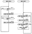
図12は、操作判定処理Mおよび制御信号対応処理Tのフローチャートである。図12を参照して、通信端末装置500が行なう操作判定処理Mでは、まず、ステップS10の処理が行なわれる。
FIG. 12 is a flowchart of the operation determination process M and the control signal handling process T. Referring to FIG. 12, in operation determination process M performed by
ステップS10では、制御部510が、制御操作があるか否かを判定する。ここで、制御操作は、表示部530に対するタッチ操作、または、通信端末装置500の外部に設けられた複数の外部ボタンのいずれかの押下操作である。
In step S10,
複数の外部ボタンは、方向ボタン541A,541B,541C,541D、決定ボタン541E、機能ボタン542A,542B,543A,543B、数字ボタン群546に含まれる12個の数字ボタンである。ステップS10において、YESならば、ステップS12に進む。一方、ステップS10において、NOならば、再度、ステップS10の処理が行なわれる。
The plurality of external buttons are twelve numeric buttons included in the
ステップS12では、制御部510が、通信部560を利用して、制御操作に対応する、映像表示装置600を操作するための制御信号としてのリモコン信号を、映像表示装置600へ送信する。ステップS12の処理が終了すると、再度、ステップS10の処理が行なわれる。
In step S <b> 12,
映像表示装置600が行なう制御信号対応処理Tでは、まず、ステップS20の処理が行なわれる。
In the control signal corresponding process T performed by the
ステップS20では、制御部610が、制御信号としてのリモコン信号を受信したか否かを判定する。ステップS20において、YESならば、ステップS22に進む。一方、ステップS20において、NOならば、再度、ステップS20の処理が行なわれる。
In step S20,
ステップS22では、制御信号対応処理が行なわれる。制御信号対応処理では、制御部610が、受信したリモコン信号に応じた処理を行なう。ステップS22の処理が終了すると、再度、ステップS20の処理が行なわれる。
In step S22, control signal handling processing is performed. In the control signal handling process,
(制御テーブルの送信)
次に、通信端末装置500が、他の装置が自装置(通信端末装置500)を制御するための情報を含む制御テーブルを、映像表示装置600へ送信するための処理(以下、制御テーブル送信処理ともいう)について説明する。送信される制御テーブルは、以下の制御テーブルMD200であるとする。制御テーブルMD200は、記憶部520に記憶されているとする。
(Send control table)
Next, the
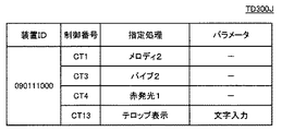
図13は、一例としての制御テーブルMD200を示す図である。図13を参照して、制御テーブルMD200において、「装置ID」とは、装置を識別するための情報である。通信端末装置500の装置IDは、たとえば、電話番号であるとする。なお、装置IDは、電話番号以外のものであってもよい。「リモコンモード」の項目の「オン」は、通信端末装置500が、リモコンモードに設定されていることを示す。なお、「リモコンモード」の項目が、「オフ」の場合、通信端末装置500が、リモコンモードに設定されていないことを示す。
FIG. 13 is a diagram illustrating a control table MD200 as an example. Referring to FIG. 13, in control table MD200, “device ID” is information for identifying a device. The device ID of
「処理」とは、通信端末装置500が実行可能な処理を示す。以下においては、「処理」の項目に記載されている情報は、処理を特定するための処理特定情報である。「処理」の項目の「メロディ1〜25」とは、音声出力部572により25種類のメロディを鳴らす処理を示す。なお、メロディは、25種類に限定されることはない。以下の「処理」の項目についても同様に、1〜m(自然数)と記載している場合、m種類に限定されることはない。
“Processing” indicates processing that can be executed by the
「処理」の項目の「音楽1〜20」とは、音声出力部572により20種類の音楽を鳴らす処理を示す。「処理」の項目の「バイブ1〜5」とは、振動部579が5種類の振動パターンで振動する処理を示す。
“
「処理」の項目の「赤発光1〜2」とは、LED576が2種類の赤の発光パターンを行なう処理を示す。「処理」の項目の「青発光1〜3」とは、LED576が3種類の青の発光パターンを行なう処理を示す。「処理」の項目の「スピーカー」とは、音声出力部570により音声を出力する処理を示す。なお、「処理」の項目の「スピーカー」とは、音声出力部572により音声を出力する処理であってもよい。
“Red
「処理」の項目の「カメラ1(静止画)」とは、撮像部578の撮像処理により静止画像データを取得する処理を示す。「処理」の項目の「カメラ2(動画)」とは、撮像部578の撮像処理により動画像データを取得する処理を示す。「処理」の項目の「カメラ3(バーコード)」とは、撮像部578の撮像処理によりバーコード(たとえば、QR(Quick Response)コード(登録商標))を取得する処理を示す。「処理」の項目の「カメラ4(顔認証)」とは、撮像部578の撮像処理により取得した顔の画像により認証を行なう処理を示す。
“Camera 1 (still image)” in the “Processing” item indicates a process of acquiring still image data by the imaging process of the
「処理」の項目の「指紋認証」とは、生体情報取得部577の動作により取得した指紋情報により認証を行なう処理を示す。「処理」の項目の「電子マネー」とは、RFID580により電子マネーを使用する処理を示す。「処理」の項目の「テロップ表示」とは、表示部530により文字、画像等をテロップ表示する処理を示す。
“Fingerprint authentication” in the item “Process” indicates a process of performing authentication using fingerprint information acquired by the operation of the biometric
なお、前述の各種処理を通信端末装置500に実行させるためのデータは、予め記憶部520に記憶されている。
Note that data for causing the
「制御番号」とは、前述した各種処理を特定するための番号である。「状態」とは、対応する「処理」が、通信端末装置500で実行することが許可されているか否かを示す。各処理に対応する「状態」の項目は、通信端末装置500において、アプリケーションプログラム等により、ユーザが「許可」および「不許可」のいずれかを設定可能であるとする。
The “control number” is a number for specifying the various processes described above. The “state” indicates whether or not the corresponding “processing” is permitted to be executed by the
なお、通信端末装置500は、音を発生しないモード(以下、サイレンモード)に設定することができる。また、以下においては、通信端末装置500が音を発生するモードを、音発生モードともいう。通信端末装置500を、サイレンモードおよび音発生モードのいずれかに設定するための操作は、数字ボタン群546に含まれる記号ボタン1の長押操作であるとする。
通信端末装置500が、サイレンモードの場合、制御テーブルMD200において、通信端末装置500が音を発生する処理(たとえば、「メロディ1〜25」)は、「不許可」に設定される。
When
なお、通信端末装置500が実行可能な処理(以下、端末実行可能処理ともいう)は、上記処理に限定されることはない。端末実行可能処理は、たとえば、表示部530において、バックライトのみを光らす処理であってもよい。また、端末実行可能処理は、通信端末装置500に設けられた図示しないストロボを光らす処理であってもよい。また、端末実行可能処理は、ウインドウ画面を表示する処理であってもよい。
Note that a process that can be executed by communication terminal device 500 (hereinafter also referred to as a terminal executable process) is not limited to the above process. The terminal executable process may be, for example, a process in which only the backlight is illuminated in the
次に、制御テーブル送信処理について説明する。ここで、映像表示装置600は、待機モードであるとする。前述したように、待機モードとは、表示部630に画像が表示されていない状態であって、主電源がオフでない状態である。映像表示装置600は、待機モードであっても、他の装置または通信部50とデータ通信可能であるとする。なお、映像表示装置600は、通常モードであってもよい。
Next, the control table transmission process will be described. Here, it is assumed that the
図14は、制御テーブル送信処理のフローチャートである。図14では、通信端末装置500および映像表示装置600の各々において行なわれる処理を示す。
FIG. 14 is a flowchart of the control table transmission process. FIG. 14 shows processing performed in each of
映像表示装置600では、まず、ステップS240の処理が行なわれる。
ステップS240では、接続信号送信処理が行なわれる。接続信号送信処理では、制御部610が、無線データ通信機能により接続信号を送信する。以下においては、無線データ通信機能は、一例として、Bluetooth(登録商標)を使用した通信機能であるとする。接続信号は、当該接続信号を受信した装置とデータ通信を行なうための信号である。
In
In step S240, connection signal transmission processing is performed. In the connection signal transmission process,
上記処理により送信される接続信号は、映像表示装置600の設置位置から、一例として、半径10メートルの領域内まで到達するものとする。すなわち、上記処理により、映像表示装置600の設置位置から、一例として、半径10メートルの領域(以下、接続信号受信可能領域ともいう)内にある装置は、接続信号を受信可能であるとする。その後、このステップS240の処理は終了する。
It is assumed that the connection signal transmitted by the above processing reaches from the installation position of the
ここで、通信端末装置500は、電源がオン状態であり、かつ、接続信号受信可能領域内にあるとする。通信端末装置500では、まず、ステップS210の処理が行なわれる。
Here,
ステップS210では、制御部510が、映像表示装置600とデータ通信可能であるか否かを判定する。すなわち、制御部510は、通信端末装置500と映像表示装置600との距離が所定の距離以下となる位置に配置された映像表示装置600とデータ通信可能であるか否かを判定する。具体的には、制御部510が、接続信号を受信したか否かを判定する。
In step S210,
ステップS210において、YESならば、ステップS211に進む。一方、ステップS210において、NOならば、再度、ステップS210の処理が行なわれる。ここでは、接続信号を受信したとして、ステップS211に進む。ステップS210において、YESと判定される場合は、制御部510が、映像表示装置600とデータ通信可能であると判定した場合である。
If YES in step S210, the process proceeds to step S211. On the other hand, if NO at step S210, the process at step S210 is performed again. Here, assuming that a connection signal has been received, the process proceeds to step S211. If YES is determined in step S210,
ステップS211では、制御部510が、制御テーブルを、映像表示装置600へ送信する。送信される制御テーブルは、図13の制御テーブルMD200であるとする。そして、制御テーブル送信処理における通信端末装置500の処理は終了する。
In step S <b> 211,
映像表示装置600では、ステップS240の処理の後、ステップS241に進む。
ステップS241では、制御部610が、制御テーブルを受信したか否かを判定する。ステップS241において、YESならば、ステップS242に進む。一方、ステップS241において、NOならば、再度、ステップS240の処理が行なわれる。ここでは、制御テーブルMD200を受信したとして、ステップS242に進む。
In the
In step S241,
ステップS242では、制御部610が、受信した制御テーブルを記憶部620に記憶させる。これにより、記憶部620には、制御テーブルMD200が記憶される。そして、制御テーブル送信処理における映像表示装置600の処理は終了する。
In step S242,
(制御テーブルの変更)
通信端末装置500が、記憶している制御テーブルは、前述したサイレンモードの設定等により、「状態」の項目が変更される。制御テーブルが変更された場合、制御部510は、変更された「状態」の情報(以下、状態変化情報ともいう)のみを、映像表示装置600へ送信する。
(Change control table)
In the control table stored in the
映像表示装置600では、制御部610が、状態変化情報を受信すると、受信した状態変化情報に基づいて、記憶部620に記憶されている制御テーブルを変更する。
In
ここで、通信端末装置500が、サイレンモードに設定されたとする。この場合、制御部610が受信する状態変化情報は、図13の制御テーブルMD200において、制御番号CT1,CT2,CT6の各々に対応する状態が、「許可」から「不許可」に変更されたことを示す情報となる。また、記憶部620には、制御テーブルMD200が記憶されているとする。
Here, it is assumed that
この場合、制御部610は、制御テーブルMD200において、制御番号CT1,CT2,CT6の各々に対応する状態を、「許可」から「不許可」に変更する。以上のように、記憶部620に記憶されている制御テーブルは変更される。
In this case,
なお、通信端末装置500をユーザが操作している場合、制御テーブルにおいて、ユーザの操作を邪魔するような処理(以下、迷惑処理ともいう)の「状態」の項目が、自動的に「許可」から「不許可」に変更されてもよい。迷惑処理は、たとえば、テロップ表示である。なお、上記のユーザの操作により通信端末装置500で行なわれる処理は、たとえば、電子メールの作成処理、WEBサイトの閲覧処理、電話等である。制御テーブルが変更された場合、前述したように、制御部510は、変更された「状態」の情報のみを、映像表示装置600へ送信する。
When the user operates the
(通話中の処理)
次に、通信端末装置500が他の装置(たとえば、携帯電話)と通話中である場合に行なわれる処理(以下、通話中処理ともいう)について説明する。以下においては、通話中処理において、通信端末装置500が行なう処理を、通話中処理Mともいう。また、通話中処理において、映像表示装置600が行なう処理を、通話中処理Tともいう。通話中処理Mおよび通話中処理Tの各々は、他の処理とは独立して行なわれる処理である。
(Process during call)
Next, processing performed when
図15は、通話中処理Mおよび通話中処理Tのフローチャートである。図15を参照して、通信端末装置500が行なう通話中処理Mでは、ステップS311の処理が行なわれる。
FIG. 15 is a flowchart of the mid-call process M and the mid-call process T. Referring to FIG. 15, in mid-call process M performed by
ステップS311では、制御部510が、自装置が通話中であるか否かを判定する。ステップS311において、YESならば、ステップS312に進む。一方、ステップS311において、NOならば、再度、ステップS311の処理が行なわれる。ここでは、通信端末装置500が通話中であるとして、ステップS312に進む。
In step S311,
ステップS312では、制御部510が、無線データ通信機能により、通話中報知情報Mを、映像表示装置600へ送信する。通話中報知情報Mは、通信端末装置500が通話中である旨を報知するための情報である。なお、送信される通話中報知情報Mには、当該通話中報知情報Mを送信した装置の装置ID(たとえば、“090111000”)が含まれる。そして、ステップS312の処理は終了する。
In step S312,
映像表示装置600が行なう通話中処理Tでは、まず、ステップS341の処理が行なわれる。
In the in-call process T performed by the
ステップS341では、制御部610が、通話中報知情報Mを受信したか否かを判定する。ステップS341において、YESならば、ステップS342に進む。一方、ステップS341において、NOならば、後述するステップS343に進む。ここで、装置ID“090111000”を含む通話中報知情報Mを受信したとして、ステップS342に進む。
In step S341,
ステップS342では、制御部610が、受信した通話中報知情報Mを記憶部620に記憶させる。なお、受信した通話中報知情報Mに含まれる装置IDを含む通話中報知情報Mが、既に記憶部620に記憶されている場合は、通話中報知情報Mを記憶させる処理は行なわれない。そして、ステップS342の処理は終了する。
In step S <b> 342,
通信端末装置500が行なうで通話中処理Mでは、ステップS312の処理の後、ステップS313に進む。
In the communication process M performed by the
ステップS313では、制御部510が、通話が終了したか否かを判定する。ステップS313において、YESならば、ステップS314に進む。一方、ステップS313において、NOならば、再度、ステップS313の処理が行なわれる。ここでは、通話が終了したとして、ステップS314に進む。
In step S313,
ステップS314では、制御部510が、無線データ通信機能により、通話終了報知情報Mを、映像表示装置600へ送信する。通話終了報知情報Mは、通信端末装置500の通話が終了した旨を報知するための情報である。なお、送信される通話終了報知情報Mには、当該通話終了報知情報Mを送信した装置の装置ID(たとえば、“090111000”)が含まれる。そして、ステップS314の処理は終了し、再度、ステップS311の処理が行なわれる。
In step S314,
映像表示装置600が行なう通話中処理Tでは、ステップS342の処理の後、ステップS343に進む。
In the in-call process T performed by the
ステップS343では、制御部610が、通話終了報知情報Mを受信したか否かを判定する。ステップS343において、YESならば、ステップS344に進む。一方、ステップS343において、NOならば、再度、ステップS341の処理が行なわれる。ここでは、装置ID“090111000”を含む通話終了報知情報Mを受信したとして、ステップS344に進む。
In step S343,
ステップS344では、通話終了報知情報M削除処理が行なわれる。通話終了報知情報M削除処理では、制御部610が、受信した通話終了報知情報Mに含まれる装置IDを含む通話中報知情報Mが記憶部620に記憶されている場合、当該通話中報知情報Mを削除する。なお、受信した通話終了報知情報Mに含まれる装置IDを含む通話中報知情報Mが記憶部620に記憶されていない場合、通話中報知情報Mの削除の処理は行なわれない。そして、再度、ステップS341の処理が行なわれる。
In step S344, a call end notification information M deletion process is performed. In the call end notification information M deletion process, when the
なお、通信端末装置500に電話がかかってきた場合、通信端末装置500が、自動的に、たとえば、映像表示装置600から出力される音声を消音するための処理、映像表示装置600で再生されているコンテンツを一時停止させるための処理等を行なってもよい。
Note that when a call is made to the
(動作状態に応じた制御)
次に、映像表示装置600が、自装置(映像表示装置600)の動作状態に応じて、通信端末装置500を制御するための処理(以下、装置制御処理ともいう)について説明する。以下においては、装置制御処理において、通信端末装置500が行なう処理を、装置制御処理Mともいう。また、装置制御処理において、映像表示装置600が行なう処理を、装置制御処理Tともいう。装置制御処理Mおよび装置制御処理Tの各々は、他の処理とは独立して行なわれる処理である。ここで、映像表示装置600は、待機モードであるとする。また、映像表示装置600の記憶部620には、図13の制御テーブルMD200が記憶されているとする。
(Control according to the operating state)
Next, processing for the
図16は、装置制御処理Mおよび装置制御処理Tのフローチャートである。図16を参照して、映像表示装置600が行なう装置制御処理Tでは、まず、ステップS441の処理が行なわれる。
FIG. 16 is a flowchart of the device control process M and the device control process T. Referring to FIG. 16, in apparatus control process T performed by
ステップS441では、状態判定処理Tが行なわれる。状態判定処理Tでは、制御部610が、自装置(映像表示装置600)の動作状態を判定する。ここでは、制御部610は、自装置(映像表示装置600)の動作状態が、待機モードであると判定する。そしてステップS442に進む。
In step S441, a state determination process T is performed. In the state determination process T, the
ステップS442では、制御部610が、記憶部620に記憶されている制御テーブルに記載される装置IDにより特定(識別)される通信端末装置500が通話中であるか否かを判定する。具体的には、制御部610が、制御テーブルに記載される装置IDを含む通話中報知情報Mが、図15のステップS342の処理により、記憶部620に記憶されているか否かを判定する。ステップS442において、YESならば、この装置制御処理Tは終了する。一方、ステップS442において、NOならば、ステップS443に進む。
In step S442,
ここで、記憶部620に記憶されている制御テーブルは、図13の制御テーブルMD200であるとする。また、制御テーブルMD200に記載される装置ID“090111000”を含む通話中報知情報Mが、記憶部620に記憶されてないとする。すなわち、制御テーブルMD200に記載される装置ID“090111000”により特定(識別)される通信端末装置500が通話中でないとする。この場合、ステップS442において、NOと判定されて、ステップS443に進む。
Here, it is assumed that the control table stored in the
ステップS443では、制御データ送信処理が行なわれる。制御データ送信処理では、制御部610が、判定された動作状態に応じた制御データを、記憶部620に記憶されている制御テーブルに記載される装置IDにより特定(識別)される通信端末装置500へ送信する。ここで、記憶部620に記憶されている制御テーブルは、図13の制御テーブルMD200であるとする。
In step S443, control data transmission processing is performed. In the control data transmission process, the
ここで、送信される制御データは、制御テーブルMD200において、「許可」となっている処理に基づいて生成されるデータである。送信される制御データは、以下の制御データTD300であるとする。そして、ステップS443の処理は終了し、この装置制御処理Tは終了する。 Here, the control data to be transmitted is data generated based on the processing that is “permitted” in the control table MD200. It is assumed that the control data to be transmitted is the following control data TD300. And the process of step S443 is complete | finished and this apparatus control process T is complete | finished.
図17は、一例としての制御データTD300を示す図である。図17を参照して、制御データTD300において、「装置ID」とは、制御データTD300の送信先の装置のIDである。「制御番号」は、図13で説明したので詳細な説明は繰り返さない。 FIG. 17 is a diagram showing control data TD300 as an example. Referring to FIG. 17, in control data TD300, “device ID” is an ID of a transmission destination device of control data TD300. Since “control number” has been described with reference to FIG. 13, detailed description thereof will not be repeated.
「指定処理」とは、制御テーブル(たとえば、制御テーブルMD200)の制御番号に対応する処理のうち、少なくとも1つの処理である。たとえば、制御番号“CT1”に対応する「メロディ2」は、制御テーブルMD200の制御番号“CT1”に対応するメロディ1〜25のうちの1つである。
The “designation process” is at least one process among the processes corresponding to the control numbers in the control table (for example, the control table MD200). For example, “
「パラメータ」とは、対応する「指定処理」が必要な場合に記述される。たとえば、「指定処理」が「テロップ表示」の場合、対応するパラ−メータが、「電源オン」である場合、映像表示装置600を待機モードから通常モードに移行させるためのボタンが、通信端末装置500の表示部530に表示される。
“Parameter” is described when a corresponding “designation process” is required. For example, when the “designation process” is “telop display” and the corresponding parameter is “power on”, a button for shifting the
再び、図16を参照して、通信端末装置500が行なう装置制御処理Mでは、まず、ステップS411の処理が行なわれる。
Referring to FIG. 16 again, in device control process M performed by
ステップS411では、制御部510が、自装置宛の制御データを受信したか否かを判定する。自装置宛の制御データとは、当該制御データに自装置の装置IDが記載されているデータである。ステップS411において、YESならば、ステップS412に進む。一方、ステップS411において、NOならば、再度、ステップS411の処理が行なわれる。ここでは、制御データTD300を受信したとして、ステップS412に進む。
In step S411,
ステップS412では、制御部510が、受信した制御データを、記憶部520に記憶させる。この処理により、記憶部520には、制御データTD300が記憶されるとする。そして、ステップS414に進む。
In step S412,
ステップS414では、制御データ対応処理Mが行なわれる。制御データ対応処理Mでは、受信した制御データに対応した処理が行なわれる。 In step S414, a control data handling process M is performed. In the control data corresponding process M, a process corresponding to the received control data is performed.
ここで、受信した制御データは、制御データTD300であるとする。この場合、制御データ対応処理Mでは、制御部510が、音声出力処理M、発光処理Mおよびテロップ表示処理Mを、同時に行なう。なお、音声出力処理M、発光処理Mおよびテロップ表示処理Mは、同時に行なわれなくてもよい。
Here, it is assumed that the received control data is control data TD300. In this case, in the control data handling process M, the
音声出力処理Mでは、制御部510が、記憶部520に記憶されているメロディ2データを、音声出力部572へ送信する。メロディ2データは、制御データTD300において、制御番号CT1に対応するデータである。メロディ2データは、メロディ2に基づく音声のデータである。音声出力部572は、メロディ2データを受信すると、メロディ2データに基づく音声を、音声出力部572に含まれるスピーカーから出力する。
In audio output process M,
発光処理Mでは、制御部510が、記憶部520に記憶されている赤発行1データを、LED576へ送信する。赤発行1データは、制御データTD300において、制御番号CT4に対応するデータである。赤発行1データは、赤の光を、所定のパターンで発光するためのデータである。LED576は、赤発行1データを受信すると、赤発行1データに基づくパターンで、赤の光を発光する。
In the light emission process M, the
テロップ表示処理Mは、制御部510が、VDP532を利用して、以下のテロップ画像MG210を、現在表示部530に表示されている端末画像の前面に表示させた報知画像MG200を、表示部530に表示させる。ここで、端末画像は、たとえば、表示部530において、電子メールを閲覧中であれば、電子メールの文章が表示された画像となる。以上により、装置制御処理Mの処理は終了する。
In the telop display processing M, the
図18は、一例としての報知画像MG200を示す図である。図18を参照して、報知画像MG200には、端末画像の前面にテロップ画像MG210が配置される。 FIG. 18 is a diagram showing a notification image MG200 as an example. Referring to FIG. 18, in notification image MG200, telop image MG210 is arranged in front of the terminal image.
テロップ画像MG210には、映像表示装置の電源をオンするか否かを問合せる旨のメッセージが表示される。また、テロップ画像MG210には、ボタン画像MBG216が配置される。ボタン画像MBG216は、押下処理されることにより、電源リモコン信号を、映像表示装置600へ送信するためのボタン画像である。
In telop image MG210, a message for inquiring whether to turn on the power of the video display device is displayed. In addition, a button image MBG216 is arranged in the telop image MG210. The button image MBG 216 is a button image for transmitting a power supply remote control signal to the
次に、待機モードの映像表示装置600を、通常モードに移行させるための処理について説明する。ここで、通信端末装置500の表示部530には、図18の報知画像MG200が表示されているとする。
Next, a process for shifting the
再び、図12を参照して、通信端末装置500が行なう操作判定処理Mにおいて、ステップS10では、前述したのと同様な処理が行なわれるので詳細な説明は繰り返さない。ここでは、図18のボタン画像MBG216を押下するための制御操作があったとして、ステップS12に進む。
Referring to FIG. 12 again, in operation determination process M performed by
ステップS12では、制御部510が、制御信号としての電源リモコン信号を、映像表示装置600へ送信する。
In step S <b> 12,
映像表示装置600が行なう制御信号対応処理Tにおいて、ステップS20では、前述したのと同様な処理が行なわれるので詳細な説明は繰り返さない。ここでは、制御信号としての電源リモコン信号を受信したとして、ステップS22に進む。
In the control signal corresponding process T performed by the
ステップS22では、制御信号対応処理が行なわれる。ここでは、制御信号対応処理において、制御部610が、前述の画像表示電源をオンにさせ、映像表示装置600を通常モードに設定する。これにより、表示部630に画像が表示可能となる。
In step S22, control signal handling processing is performed. Here, in the control signal handling process,
以上の処理が行なわれることにより、通信端末装置500が通話中である場合、制御データは、通信端末装置500へ送信されない。そのため、通信端末装置500が通話中である場合、通信端末装置500において、前述したような、制御データ対応処理Mが行なわれことはない。したがって、通信端末装置500のユーザの通話を中断させてしまうことを防ぐことができるという効果を奏する。
By performing the above processing, control data is not transmitted to
(コンテンツ表示中の処理)
次に、映像表示装置600の表示部630において、コンテンツを表示している場合の処理について説明する。以下においては、表示部630に表示されているコンテンツを表示コンテンツともいう。表示コンテンツは、図9の処理により登録した、サービスサーバ800Aが提供するサービスサイトからストリーミング配信されるコンテンツであるとする。なお、表示コンテンツは、放送信号に基づく画像(以下、TV画像ともいう)であってもよい。
(Processing during content display)
Next, processing when content is displayed on the
ここで、表示コンテンツには、当該表示コンテンツに関連する情報(以下、コンテンツ関連情報ともいう)が含まれるとする。なお、表示コンテンツは、たとえば、サッカーの試合の番組であるとする。この場合、コンテンツ関連情報は、たとえば、サッカーの試合の出場選手のプロフィールであるとする。なお、コンテンツ関連情報は、表示コンテンツの表示中に、サービスサーバ800Aから映像表示装置600へ配信される情報(プッシュ情報)であってもよい。なお、コンテンツ関連情報は、たとえば、同時刻の他のチャンネルの番組の情報、お勧め番組の情報等であってもよい。
Here, it is assumed that the display content includes information related to the display content (hereinafter also referred to as content-related information). Note that the display content is, for example, a soccer game program. In this case, it is assumed that the content-related information is, for example, a profile of a player who participated in a soccer game. The content-related information may be information (push information) distributed from the
また、映像表示装置600の記憶部620には、図13の制御テーブルMD200が記憶されているとする。
Further, it is assumed that the
再び、図16を参照して、ステップS441では、前述したように、状態判定処理Tが行なわれる。状態判定処理Tでは、制御部610が、自装置(映像表示装置600)の動作状態を判定する。ここでは、制御部610は、自装置(映像表示装置600)の動作状態は、コンテンツ関連情報を含む表示コンテンツを、表示部630が表示している状態であると判定する。
Referring to FIG. 16 again, in step S441, state determination process T is performed as described above. In the state determination process T, the
ステップS442では、前述したのと同様な処理が行なわれるので詳細な説明は繰り返さない。ここでは、制御テーブルMD200に記載される装置ID“090111000”により特定(識別)される通信端末装置500が通話中でないとする。この場合、ステップS442において、NOと判定されて、ステップS443に進む。
In step S442, the same processing as described above is performed, and therefore detailed description will not be repeated. Here, it is assumed that
ステップS443では、前述したのと同様に、制御部610が、判定された動作状態に応じた制御データを、記憶部620に記憶されている制御テーブルに記載される装置IDにより特定(識別)される通信端末装置500へ送信する。この処理により、送信される制御データは、以下の制御データTD300Aであるとする。
In step S443, as described above,
図19は、一例としての制御データTD300Aを示す図である。図19を参照して、制御データTD300Aの各項目は、図17の制御データTD300で説明したのと同様なので詳細な説明は繰り返さない。制御データTD300Aにおいて、「テロップ表示」に対応するパラメータが「関連情報」である場合、コンテンツ関連情報を表示させるためのボタンが通信端末装置500の表示部530に表示される。
FIG. 19 is a diagram showing control data TD300A as an example. Referring to FIG. 19, each item of control data TD300A is the same as that described for control data TD300 in FIG. 17, and therefore detailed description will not be repeated. In the control data TD300A, when the parameter corresponding to “telop display” is “related information”, a button for displaying the content related information is displayed on the
再び、図16を参照して、通信端末装置500が行なう装置制御処理MのステップS411では、前述したのと同様な処理が行なわれるので詳細な説明は繰り返さない。ここでは、制御データTD300Aを受信したとして、ステップS412に進む。
Referring to FIG. 16 again, in step S411 of apparatus control process M performed by
ステップS412では、前述したのと同様な処理が行なわれるので詳細な説明は繰り返さない。この処理により、制御データTD300Aが記憶されるとする。 In step S412, the same processing as described above is performed, and thus detailed description will not be repeated. It is assumed that control data TD300A is stored by this processing.
ステップS414では、前述したように、制御データ対応処理Mが行なわれる。制御データ対応処理Mでは、受信した制御データに対応した処理が行なわれる。 In step S414, as described above, the control data handling process M is performed. In the control data corresponding process M, a process corresponding to the received control data is performed.
ここで、受信した制御データは、制御データTD300Aであるとする。この場合、制御データ対応処理Mでは、制御部510が、音声出力処理M、発光処理Mおよびテロップ表示処理MAを、同時に行なう。なお、音声出力処理M、発光処理Mおよびテロップ表示処理MAは、同時に行なわれなくてもよい。
Here, it is assumed that the received control data is control data TD300A. In this case, in the control data corresponding process M, the
音声出力処理Mおよび発光処理Mは、前述したのと同様なので詳細な説明は繰り返さない。 Since the audio output process M and the light emission process M are the same as described above, detailed description will not be repeated.
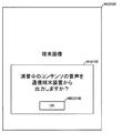
テロップ表示処理MAでは、制御部510が、VDP532を利用して、以下のテロップ画像MG210Aを、現在表示部530に表示されている端末画像の前面に表示させた報知画像MG200Aを、表示部530に表示させる。
In the telop display process MA, the
図20は、一例としての報知画像MG200Aを示す図である。図20を参照して、報知画像MG200Aには、端末画像の前面にテロップ画像MG210Aが配置される。 FIG. 20 is a diagram illustrating a notification image MG200A as an example. Referring to FIG. 20, in notification image MG200A, telop image MG210A is arranged in front of the terminal image.
テロップ画像MG210Aには、関連情報を表示するか否かを問合せる旨のメッセージが表示される。また、テロップ画像MG210Aには、ボタン画像MBG216Aが配置される。ボタン画像MBG216Aは、押下処理されることにより、関連情報表示リモコン信号を、映像表示装置600へ送信するためのボタン画像である。関連情報表示リモコン信号は、コンテンツ関連情報を、表示部530に表示させるためのリモコン信号である。
In the telop image MG210A, a message for inquiring whether or not to display related information is displayed. In addition, a button image MBG216A is arranged in the telop image MG210A. Button image MBG 216 </ b> A is a button image for transmitting a related information display remote control signal to
次に、コンテンツ関連情報を、表示部530に表示させるための処理について説明する。ここで、通信端末装置500の表示部530には、図20の報知画像MG200Aが表示されているとする。
Next, processing for displaying content-related information on the
再び、図12を参照して、通信端末装置500が行なう操作判定処理Mにおいて、ステップS10では、前述したのと同様な処理が行なわれるので詳細な説明は繰り返さない。ここでは、図18のボタン画像MBG216Aを押下するための制御操作があったとして、ステップS12に進む。
Referring to FIG. 12 again, in operation determination process M performed by
ステップS12では、制御部510が、制御信号としての関連情報表示リモコン信号を、映像表示装置600へ送信する。
In step S12,
映像表示装置600が行なう制御信号対応処理Tにおいて、ステップS20では、前述したのと同様な処理が行なわれるので詳細な説明は繰り返さない。ここでは、制御信号としての関連情報表示リモコン信号を受信したとして、ステップS22に進む。
In the control signal corresponding process T performed by the
ステップS22では、制御信号対応処理が行なわれる。ここでは、制御信号対応処理において、制御部610が、コンテンツ関連情報を通信端末装置500へ送信する。
In step S22, control signal handling processing is performed. Here, in the control signal handling process,
通信端末装置500では、制御部510がコンテンツ関連情報を受信する。そして、制御部510は、VDP532を利用して、コンテンツ関連情報を表示させた関連情報表示画像を、表示部530に表示させる。前述したように、コンテンツ関連情報は、サッカーの試合の出場選手のプロフィールであるとする。
In
以上の処理が行なわれることにより、映像表示装置600に表示されている表示コンテンツの関連情報がある場合、映像表示装置600の表示部630に、関連情報がある旨の表示等を行なう必要がない。そのため、ユーザによる表示コンテンツの視聴を妨げることを防ぐことができるという効果を奏する。
By performing the above processing, when there is related information of the display content displayed on the
また、映像表示装置600に表示されている表示コンテンツの関連情報がある場合、通信端末装置500において、音、光等で報知することができる。したがって、通信端末装置500のユーザといった特定のユーザに、表示コンテンツの関連情報があることを容易に知らせることができるという効果を奏する。
Further, when there is related information of the display content displayed on the
また、映像表示装置600に表示コンテンツを表示させた状態で、別の装置である通信端末装置500で、表示コンテンツの関連情報(コンテンツ関連情報)を参照することができる。したがって、コンテンツの見易さを損ねることなく、通信端末装置500において関連情報を参照することができるという効果を奏する。
Further, in the state where the display content is displayed on the
以上により、コンテンツの見易さを損ねることなく、通信端末装置500において多種多様な処理を行なうことができるという効果を奏する。
As described above, the
(タイマー処理)
ここで、映像表示装置600は、所定時刻に、所定のチャンネルの番組を表示するタイマー処理を行なうとする。タイマー処理は、プログラム180Aに含まれるタイマープログラムの実行により行なわれる。
(Timer processing)
Here, it is assumed that
次に、映像表示装置600が行なうタイマー処理により、所定時刻に、所定のチャンネルの番組を表示する場合の処理について説明する。
Next, processing when a program of a predetermined channel is displayed at a predetermined time by the timer processing performed by the
具体的には、タイマープログラムにより、待機モードの映像表示装置600が、所定時刻(たとえば、午前6時)に通常モードに移行し、所定のチャンネル番号(たとえば、“3”)の番組を表示するように、ユーザにより設定されている状況の処理について説明する。当該状況は、ユーザが、たとえば、所定時刻に、所望のチャンネルの番組を視聴するために予約設定をしている状況である。
More specifically, the timer program causes the
また、映像表示装置600の記憶部620には、図13の制御テーブルMD200が記憶されているとする。
Further, it is assumed that the
再び、図16を参照して、ステップS441では、前述したように、状態判定処理Tが行なわれる。状態判定処理Tでは、制御部610が、自装置(映像表示装置600)の動作状態を判定する。ここで、現在の時刻が、タイマープログラムにより設定された所定時刻(たとえば、午前6時)になったとする。この場合、制御部610は、自装置(映像表示装置600)の動作状態は、タイマー処理による通常モード移行状態と判定する。
Referring to FIG. 16 again, in step S441, state determination process T is performed as described above. In the state determination process T, the
ステップS442では、前述したのと同様な処理が行なわれるので詳細な説明は繰り返さない。ここでは、制御テーブルMD200に記載される装置ID“090111000”により特定(識別)される通信端末装置500が通話中でないとする。この場合、ステップS442において、NOと判定されて、ステップS443に進む。
In step S442, the same processing as described above is performed, and therefore detailed description will not be repeated. Here, it is assumed that
ステップS443では、前述したのと同様に、制御部610が、判定された動作状態に応じた制御データを、記憶部620に記憶されている制御テーブルに記載される装置IDにより特定(識別)される通信端末装置500へ送信する。この処理により、送信される制御データは、以下の制御データTD300Bであるとする。
In step S443, as described above,
図21は、一例としての制御データTD300Bを示す図である。図21を参照して、制御データTD300Bの各項目は、図17の制御データTD300で説明したのと同様なので詳細な説明は繰り返さない。制御データTD300Bにおいて、「テロップ表示」に対応するパラメータが「タイマー通常モード移行」である場合、映像表示装置600を待機モードから通常モードに移行させるためのボタンが、通信端末装置500の表示部530に表示される。
FIG. 21 is a diagram showing control data TD300B as an example. Referring to FIG. 21, each item of control data TD300B is the same as that described for control data TD300 in FIG. 17, and therefore detailed description will not be repeated. In the control data TD300B, when the parameter corresponding to “telop display” is “shift to normal timer mode”, a button for shifting the
再び、図16を参照して、通信端末装置500が行なう装置制御処理MのステップS411では、前述したのと同様な処理が行なわれるので詳細な説明は繰り返さない。ここでは、制御データTD300Bを受信したとして、ステップS412に進む。
Referring to FIG. 16 again, in step S411 of apparatus control process M performed by
ステップS412では、前述したのと同様な処理が行なわれるので詳細な説明は繰り返さない。この処理により、制御データTD300Bが記憶されるとする。 In step S412, the same processing as described above is performed, and thus detailed description will not be repeated. It is assumed that control data TD300B is stored by this processing.
ステップS414では、前述したように、制御データ対応処理Mが行なわれる。制御データ対応処理Mでは、受信した制御データに対応した処理が行なわれる。 In step S414, as described above, the control data handling process M is performed. In the control data corresponding process M, a process corresponding to the received control data is performed.
ここで、受信した制御データは、制御データTD300Bであるとする。この場合、制御データ対応処理Mでは、制御部510が、音声出力処理M、発光処理Mおよびテロップ表示処理MBを、同時に行なう。なお、音声出力処理M、発光処理Mおよびテロップ表示処理MBは、同時に行なわれなくてもよい。
Here, it is assumed that the received control data is control data TD300B. In this case, in the control data handling process M, the
音声出力処理Mおよび発光処理Mは、前述したのと同様なので詳細な説明は繰り返さない。 Since the audio output process M and the light emission process M are the same as described above, detailed description will not be repeated.
テロップ表示処理MBでは、制御部510が、VDP532を利用して、以下のテロップ画像MG210Bを、現在表示部530に表示されている端末画像の前面に表示させた報知画像MG200Bを、表示部530に表示させる。
In the telop display processing MB, the
図22は、一例としての報知画像MG200Bを示す図である。図22を参照して、報知画像MG200Bには、端末画像の前面にテロップ画像MG210Bが配置される。 FIG. 22 is a diagram showing a notification image MG200B as an example. Referring to FIG. 22, in notification image MG200B, telop image MG210B is arranged in front of the terminal image.
テロップ画像MG210Bには、設定された時刻になった旨のメッセージと、映像表示装置の電源をオンするか否かを問合せる旨のメッセージとが表示される。また、テロップ画像MG210Bには、ボタン画像MBG216Bが配置される。ボタン画像MBG216Bは、押下処理されることにより、設定チャネル表示電源リモコン信号を、映像表示装置600へ送信するためのボタン画像である。設定チャネル表示電源リモコン信号は、映像表示装置600を、通常モードに設定し、設定したチャネルを映像表示装置600で表示するためのリモコン信号である。
In the telop image MG210B, a message indicating that the set time has come and a message indicating whether or not to turn on the power of the video display device are displayed. Further, the button image MBG216B is arranged in the telop image MG210B. Button image MBG 216 </ b> B is a button image for transmitting a set channel display power source remote control signal to
次に、待機モードの映像表示装置600を、通常モードに移行させるための処理について説明する。ここで、通信端末装置500の表示部530には、図22の報知画像MG200Bが表示されているとする。
Next, a process for shifting the
再び、図12を参照して、通信端末装置500が行なう操作判定処理Mにおいて、ステップS10では、前述したのと同様な処理が行なわれるので詳細な説明は繰り返さない。ここでは、図22のボタン画像MBG216Bを押下するための制御操作があったとして、ステップS12に進む。
Referring to FIG. 12 again, in operation determination process M performed by
ステップS12では、制御部510が、制御信号としての設定チャネル表示電源リモコン信号を、映像表示装置600へ送信する。
In step S <b> 12,
映像表示装置600が行なう制御信号対応処理Tにおいて、ステップS20では、前述したのと同様な処理が行なわれるので詳細な説明は繰り返さない。ここでは、制御信号としての設定チャネル表示電源リモコン信号を受信したとして、ステップS22に進む。
In the control signal corresponding process T performed by the
ステップS22では、制御信号対応処理が行なわれる。ここでは、制御信号対応処理において、制御部610が、前述の画像表示電源をオンにさせ、映像表示装置600を通常モードに設定する。そして、制御部610が、チューナ505に、設定されたチャンネルの番組を表示させるため指示を送る。これにより、表示部630に、設定されたチャンネルの番組の画像が表示される。
In step S22, control signal handling processing is performed. Here, in the control signal handling process,
以上の処理が行なわれることにより、通信端末装置500が、映像表示装置600の近傍にない場合は、映像表示装置600は、自動的に通常モードに移行することはない。すなわち、通信端末装置500のユーザが、映像表示装置600の近傍にない場合は、映像表示装置600は、自動的に通常モードに移行することはない。したがって、ユーザが、タイマー設定したことを忘れており、設定した時刻に映像表示装置600の近傍にいなくても、映像表示装置600は、テレビ等で行なわれる従来の視聴予約のように、自動的に通常モードに移行することはない。そのため、映像表示装置600の無駄な電力の消費を防ぐことができるという効果を奏する。
By performing the above processing, when
以上のように、映像表示装置600が、自装置のプログラムで動作する場合においても、本発明は適用可能である。
As described above, the present invention can be applied even when the
(コンテンツ表示中の処理の他の例1)
次に、映像表示装置600の表示部630において、コンテンツを表示している場合の他の例の処理について説明する。以下においては、表示部630に表示されているコンテンツを表示コンテンツともいう。表示コンテンツは、放送信号に基づく画像(以下、TV画像ともいう)であるとする。なお、表示コンテンツは、図9の処理により登録した、サービスサーバ800Aが提供するサービスサイトからストリーミング配信されるコンテンツであってもよい。
(Another example 1 of processing during content display)
Next, another example of processing when content is displayed on the
ここで、映像表示装置600の記憶部620には、図10のユーザデータTD50が記憶されているとする。また、映像表示装置600は、事前に、ネットワーク70と通信することにより、EPGデータを取得し、取得したEPGデータを、記憶部620に記憶させているとする。記憶部620に記憶されているEPGデータは、以下のEPGデータTD400であるとする。
Here, it is assumed that the user data TD50 of FIG. 10 is stored in the
図23は、一例としてのEPGデータTD400を示す図である。図23を参照して、EPGデータTD400は、たとえば、1日分の複数の番組情報データから構成される。「番号」とは、複数の番組情報データを特定するための番号である。「ID番号」とは、番組を識別するための番号である。「チャンネル番号」とは、放送局に割り当てられているチャンネル番号である。「放送局コード」とは、放送局に割り当てられているコード番号である。「放送局名」とは、放送局の名称である。 FIG. 23 is a diagram showing EPG data TD400 as an example. Referring to FIG. 23, EPG data TD400 is composed of a plurality of program information data for one day, for example. The “number” is a number for specifying a plurality of program information data. The “ID number” is a number for identifying a program. “Channel number” is a channel number assigned to a broadcasting station. “Broadcasting station code” is a code number assigned to a broadcasting station. “Broadcasting station name” is the name of the broadcasting station.
「タイトル」とは、対応する番組のタイトルを示す。「開始日時」とは、対応する番組の放送開始日時を示す。「終了日時」とは、対応する番組の放送終了日時を示す。「ジャンル」とは、対応する番組のジャンルを示す。「出演者」とは、対応する番組の主な出演者である。「番組内容」とは、対応する番組の簡単な内容を示す。なお、EPGデータTD400には、さらに、「音声情報」が含まれてもよい。「音声情報」とは、対応する番組の音声が、ステレオおよびモノラルのいずれであるかを示す情報である。 “Title” indicates the title of the corresponding program. The “start date / time” indicates the broadcast start date / time of the corresponding program. “End date and time” indicates the broadcast end date and time of the corresponding program. “Genre” indicates the genre of the corresponding program. “Performers” are the main performers of the corresponding program. “Program content” indicates simple content of a corresponding program. The EPG data TD400 may further include “voice information”. “Audio information” is information indicating whether the audio of the corresponding program is stereo or monaural.
また、映像表示装置600の記憶部620には、図13の制御テーブルMD200が記憶されているとする。
Further, it is assumed that the
再び、図16を参照して、ステップS441では、前述したように、状態判定処理Tが行なわれる。状態判定処理Tでは、制御部610が、自装置(映像表示装置600)の動作状態を判定する。ここで、通信端末装置500のユーザは、通信端末装置500を映像表示装置600のリモコンとして操作することにより、ザッピングを行なっているとする。ザッピングとは、短時間(たとえば、1分)において、チャンネルを頻繁に変えることである。すなわち、通信端末装置500のユーザは、ザッピングにより、同一時刻に放送されている複数の番組を確認しているとする。
Referring to FIG. 16 again, in step S441, state determination process T is performed as described above. In the state determination process T, the
この場合、制御部610は、自装置(映像表示装置600)の動作状態は、ザッピング状態であると判定する。
In this case,
ステップS442では、前述したのと同様な処理が行なわれるので詳細な説明は繰り返さない。ここでは、制御テーブルMD200に記載される装置ID“090111000”により特定(識別)される通信端末装置500が通話中でないとする。この場合、ステップS442において、NOと判定されて、ステップS443に進む。
In step S442, the same processing as described above is performed, and therefore detailed description will not be repeated. Here, it is assumed that
ステップS443では、前述したのと同様に、制御部610が、判定された動作状態に応じた制御データを、記憶部620に記憶されている制御テーブルに記載される装置IDにより特定(識別)される通信端末装置500へ送信する。
In step S443, as described above,
ステップS443の処理では、ステップS441の状態判定処理Tにより判定された状態が、ザッピング状態である場合、制御データが送信される前に、嗜好コンテンツ判定処理が行なわれる。以下においては、前述した嗜好キーワードを含むタイトルの番組を嗜好番組ともいう。すなわち、嗜好番組は、ユーザの嗜好にあった番組である。ここで、嗜好コンテンツ判定処理において、記憶部620に記憶されている、図10のユーザデータTD50が使用されるとする。この場合、嗜好キーワードは、「サッカー」、「野球」、「お笑い」である。
In the process of step S443, when the state determined by the state determination process T of step S441 is the zapping state, the preference content determination process is performed before the control data is transmitted. In the following, a program having a title including the above-described preference keyword is also referred to as a preference program. That is, the preference program is a program that meets the user's preference. Here, it is assumed that the user data TD50 of FIG. 10 stored in the
嗜好コンテンツ判定処理では、制御部610が、現時点で放送されている複数の番組のうち、ユーザデータTD50が示す嗜好キーワードを含む嗜好番組のチャンネル番号を、図23のEPGデータTD400により判定する。判定されたチャンネル番号は、一例として、“3”、“7”であるとする。そして、制御部610は、以下の制御データTD300Cを生成する。
In the preference content determination process, the
この場合、ステップS443の処理により、送信される制御データは、以下の制御データTD300Cとなる。 In this case, the control data to be transmitted is the following control data TD300C by the process of step S443.
図24は、一例としての制御データTD300Cを示す図である。図24を参照して、制御データTD300Cの各項目は、図17の制御データTD300で説明したのと同様なので詳細な説明は繰り返さない。制御データTD300Cにおいて、「バイブ2」は、図13の制御テーブルMD200の制御番号“CT3”に対応するバイブ1〜5のうちの1つである。「バイブ2」に対応するパラメータが、「3,7ボタン押下時」である場合、通信端末装置500の数字ボタン群546に含まれる、3ボタンまたは7ボタンが押下された場合。振動部579が、「バイブ2」のパターンに応じた振動を行なう。この処理により、通信端末装置500が振動する。
FIG. 24 is a diagram showing control data TD300C as an example. Referring to FIG. 24, each item of control data TD300C is the same as that described for control data TD300 in FIG. 17, and therefore detailed description will not be repeated. In the control data TD300C, “
ここで、数字ボタン群546に含まれる、3ボタンおよび7ボタンは、リモコンモードの通信端末装置500において押下されると、それぞれ、チャンネル番号“3”および“7”の番組を表示させるためのリモコン信号を、映像表示装置600へ送信するためのボタンであるとする。
Here, the 3 button and the 7 button included in the
再び、図16を参照して、通信端末装置500が行なう装置制御処理MのステップS411では、前述したのと同様な処理が行なわれるので詳細な説明は繰り返さない。ここでは、制御データTD300Cを受信したとして、ステップS412に進む。
Referring to FIG. 16 again, in step S411 of apparatus control process M performed by
ステップS412では、前述したのと同様な処理が行なわれるので詳細な説明は繰り返さない。この処理により、制御データTD300Cが記憶されるとする。 In step S412, the same processing as described above is performed, and thus detailed description will not be repeated. It is assumed that control data TD300C is stored by this processing.
ステップS414では、前述したように、制御データ対応処理Mが行なわれる。制御データ対応処理Mでは、受信した制御データに対応した処理が行なわれる。 In step S414, as described above, the control data handling process M is performed. In the control data corresponding process M, a process corresponding to the received control data is performed.
ここで、受信した制御データは、制御データTD300Cであるとする。この場合、制御データ対応処理Mでは、数字ボタン群546に含まれる、3ボタンおよび7ボタンが押下された場合、振動処理Mが行なわれる。
Here, it is assumed that the received control data is control data TD300C. In this case, in the control data handling process M, when the 3 button and 7 button included in the
振動処理Mでは、制御部510が、記憶部520に記憶されているバイブ2データを、振動部579へ送信する。バイブ2データは、制御データTD300Cにおいて、制御番号CT3に対応するデータである。バイブ2データは、振動部579を、所定のパターンで振動させるためのデータである。なお、通信端末装置500は、振動部579の振動に応じて振動する。振動部579は、バイブ2データを受信すると、バイブ2データに基づくパターンで通信端末装置500を振動させる。
In the vibration process M, the
なお、3ボタンが押下された場合、図12のステップS12の処理により、チャンネル番号“3”の番組を表示させるためのリモコン信号が、映像表示装置600に送信される。
When the 3 button is pressed, a remote control signal for displaying the program of the channel number “3” is transmitted to the
映像表示装置600は、当該リモコン信号を受信すると、表示部630に、チャンネル番号“3”の番組(嗜好番組)を表示させる。
When receiving the remote control signal,
なお、7ボタンが押下された場合の処理は、上記の3ボタンが押下された場合の処理と同様なので詳細な説明は繰り返さない。 Note that the process when the 7 button is pressed is the same as the process when the 3 button is pressed, and thus detailed description will not be repeated.
以上の処理が行なわれることにより、ユーザがザッピングを行なっている場合、ある特定のボタンを押下したときに、通信端末装置500が振動することで、押下したボタンに基づくリモコン信号により、映像表示装置600に表示される番組(コンテンツ)が、嗜好番組であることを認識することができる。
By performing the above processing, when the user is performing zapping, the
すなわち、ザッピングを行なっている場合、嗜好番組を、ユーザーが迅速に探し出すことができるという効果を奏する。 That is, when zapping is performed, there is an effect that the user can quickly find a favorite program.
(コンテンツ表示中の処理の他の例2)
次に、映像表示装置600の表示部630において、コンテンツを表示している場合の他の例の処理について説明する。以下においては、表示部630に表示されているコンテンツを表示コンテンツともいう。表示コンテンツは、放送信号に基づく画像(以下、TV画像ともいう)であるとする。なお、表示コンテンツは、図9の処理により登録した、サービスサーバ800Aが提供するサービスサイトからストリーミング配信されるコンテンツであってもよい。
(Another example 2 of processing during content display)
Next, another example of processing when content is displayed on the
ここで、表示コンテンツには、当該表示コンテンツに関連するコンテンツ関連情報が含まれるとする。なお、表示コンテンツは、たとえば、サッカーの試合の番組であるとする。コンテンツ関連情報には、表示コンテンツのタイトル名、たとえば、サッカーの試合の出場選手のプロフィールが含まれるとする。 Here, it is assumed that the display content includes content-related information related to the display content. Note that the display content is, for example, a soccer game program. It is assumed that the content-related information includes the title name of the display content, for example, the profile of players participating in a soccer game.
ここで、映像表示装置600の記憶部620には、図10のユーザデータTD50が記憶されているとする。ここで、表示コンテンツのタイトル名は、ユーザデータTD50が示す嗜好キーワード(たとえば、サッカー)を含むタイトルであるとする。以下においては、嗜好キーワードを含むタイトルの表示コンテンツを、嗜好コンテンツともいう。
Here, it is assumed that the user data TD50 of FIG. 10 is stored in the
また、映像表示装置600の記憶部620には、図13の制御テーブルMD200が記憶されているとする。
Further, it is assumed that the
再び、図16を参照して、ステップS441では、前述したように、状態判定処理Tが行なわれる。状態判定処理Tでは、制御部610が、自装置(映像表示装置600)の動作状態を判定する。ここでは、制御部610は、自装置(映像表示装置600)の動作状態は、嗜好コンテンツを、表示部630が表示している状態であると判定する。
Referring to FIG. 16 again, in step S441, state determination process T is performed as described above. In the state determination process T, the
ステップS442では、前述したのと同様な処理が行なわれるので詳細な説明は繰り返さない。ここでは、制御テーブルMD200に記載される装置ID“090111000”により特定(識別)される通信端末装置500が通話中でないとする。この場合、ステップS442において、NOと判定されて、ステップS443に進む。
In step S442, the same processing as described above is performed, and therefore detailed description will not be repeated. Here, it is assumed that
ステップS443では、前述したのと同様に、制御部610が、判定された動作状態に応じた制御データを、記憶部620に記憶されている制御テーブルに記載される装置IDにより特定(識別)される通信端末装置500へ送信する。この処理により、送信される制御データは、以下の制御データTD300Dであるとする。
In step S443, as described above,
図25は、一例としての制御データTD300Dを示す図である。図25を参照して、制御データTD300Dの各項目は、図17の制御データTD300で説明したのと同様なので詳細な説明は繰り返さない。制御データTD300Dにおいて、「テロップ表示」に対応するパラメータが「嗜好コンテンツ表示中」である場合、嗜好コンテンツ表示中の旨のメッセージが、通信端末装置500の表示部530に表示される。
FIG. 25 is a diagram showing control data TD300D as an example. Referring to FIG. 25, each item of control data TD300D is the same as that described for control data TD300 in FIG. 17, and therefore detailed description will not be repeated. In the control data TD300D, when the parameter corresponding to “telop display” is “preferred content is being displayed”, a message indicating that the preferred content is being displayed is displayed on the
再び、図16を参照して、通信端末装置500が行なう装置制御処理MのステップS411では、前述したのと同様な処理が行なわれるので詳細な説明は繰り返さない。ここでは、制御データTD300Dを受信したとして、ステップS412に進む。
Referring to FIG. 16 again, in step S411 of apparatus control process M performed by
ステップS412では、前述したのと同様な処理が行なわれるので詳細な説明は繰り返さない。この処理により、制御データTD300Dが記憶されるとする。 In step S412, the same processing as described above is performed, and thus detailed description will not be repeated. It is assumed that control data TD300D is stored by this processing.
ステップS414では、前述したように、制御データ対応処理Mが行なわれる。制御データ対応処理Mでは、受信した制御データに対応した処理が行なわれる。 In step S414, as described above, the control data handling process M is performed. In the control data corresponding process M, a process corresponding to the received control data is performed.
ここで、受信した制御データは、制御データTD300Dであるとする。この場合、制御データ対応処理Mでは、制御部510が、音声出力処理M、振動処理M、発光処理Mおよびテロップ表示処理MDを、同時に行なう。なお、音声出力処理M、振動処理M、発光処理Mおよびテロップ表示処理MDは、同時に行なわれなくてもよい。
Here, it is assumed that the received control data is control data TD300D. In this case, in the control data handling process M, the
音声出力処理M、振動処理Mおよび発光処理Mは、前述したのと同様なので詳細な説明は繰り返さない。 Since the audio output process M, the vibration process M, and the light emission process M are the same as described above, detailed description will not be repeated.
テロップ表示処理MDでは、制御部510が、VDP532を利用して、以下のテロップ画像MG210Dを、現在表示部530に表示されている端末画像の前面に表示させた報知画像MG200Dを、表示部530に表示させる。
In the telop display processing MD, the
図26は、一例としての報知画像MG200Dを示す図である。図26を参照して、報知画像MG200Dには、端末画像の前面にテロップ画像MG210Dが配置される。 FIG. 26 is a diagram showing a notification image MG200D as an example. Referring to FIG. 26, in notification image MG200D, telop image MG210D is arranged in front of the terminal image.
テロップ画像MG210Dには、あなたの嗜好に応じたコンテンツを表示中である旨のメッセージが表示される。 In telop image MG210D, a message indicating that content according to your preference is being displayed is displayed.
以上の処理が行なわれることにより、映像表示装置600に表示されるコンテンツが、ユーザは、嗜好コンテンツであることを、迅速に、認識することができる。
By performing the above processing, the user can quickly recognize that the content displayed on the
(コンテンツ表示中の処理の他の例3)
次に、映像表示装置600が消音状態に設定された場合の処理について説明する。消音状態とは、映像表示装置600が音声を発生しない状態である。ここで、映像表示装置600の表示部630には、放送信号に基づく、コンテンツとしての番組が表示されているとする。
(Other example 3 of processing during content display)
Next, processing when the
また、映像表示装置600の記憶部620には、図13の制御テーブルMD200が記憶されているとする。ここで、ユーザによる通信端末装置500の操作により、映像表示装置600は、消音状態に設定されているとする。
Further, it is assumed that the
再び、図16を参照して、ステップS441では、前述したように、状態判定処理Tが行なわれる。状態判定処理Tでは、制御部610が、自装置(映像表示装置600)の動作状態を判定する。ここでは、制御部610は、自装置(映像表示装置600)の動作状態は、消音状態であると判定する。
Referring to FIG. 16 again, in step S441, state determination process T is performed as described above. In the state determination process T, the
ステップS442では、前述したのと同様な処理が行なわれるので詳細な説明は繰り返さない。ここでは、制御テーブルMD200に記載される装置ID“090111000”により特定(識別)される通信端末装置500が通話中でないとする。この場合、ステップS442において、NOと判定されて、ステップS443に進む。
In step S442, the same processing as described above is performed, and therefore detailed description will not be repeated. Here, it is assumed that
ステップS443では、前述したのと同様に、制御部610が、判定された動作状態に応じた制御データを、記憶部620に記憶されている制御テーブルに記載される装置IDにより特定(識別)される通信端末装置500へ送信する。この処理により、送信される制御データは、以下の制御データTD300Eであるとする。
In step S443, as described above,
図27は、一例としての制御データTD300Eを示す図である。図27を参照して、制御データTD300Eの各項目は、図17の制御データTD300で説明したのと同様なので詳細な説明は繰り返さない。制御データTD300Eにおいて、「スピーカー」は、音声出力部570により音声を出力する処理を示す。なお、音声を出力するのは、音声出力部572であってもよい。
FIG. 27 is a diagram showing control data TD300E as an example. Referring to FIG. 27, each item of control data TD300E is the same as that described for control data TD300 in FIG. 17, and therefore detailed description will not be repeated. In the control data TD300E, “speaker” indicates a process of outputting sound by the
また、制御データTD300Eにおいて、「テロップ表示」に対応するパラメータが「消音状態」である場合、映像表示装置600に表示されているコンテンツの音声を通信端末装置500から出力させるためのボタンが、通信端末装置500の表示部530に表示される。
In the control data TD300E, when the parameter corresponding to “telop display” is “silenced state”, a button for outputting the audio of the content displayed on the
再び、図16を参照して、通信端末装置500が行なう装置制御処理MのステップS411では、前述したのと同様な処理が行なわれるので詳細な説明は繰り返さない。ここでは、制御データTD300Eを受信したとして、ステップS412に進む。
Referring to FIG. 16 again, in step S411 of apparatus control process M performed by
ステップS412では、前述したのと同様な処理が行なわれるので詳細な説明は繰り返さない。この処理により、制御データTD300Eが記憶されるとする。 In step S412, the same processing as described above is performed, and thus detailed description will not be repeated. It is assumed that control data TD300E is stored by this processing.
ステップS414では、前述したように、制御データ対応処理Mが行なわれる。制御データ対応処理Mでは、受信した制御データに対応した処理が行なわれる。 In step S414, as described above, the control data handling process M is performed. In the control data corresponding process M, a process corresponding to the received control data is performed.
ここで、受信した制御データは、制御データTD300Eであるとする。この場合、制御データ対応処理Mでは、制御部510が、振動処理M、発光処理Mおよびテロップ表示処理MEを、同時に行なう。なお、振動処理M、発光処理Mおよびテロップ表示処理MEは、同時に行なわれなくてもよい。
Here, it is assumed that the received control data is control data TD300E. In this case, in the control data corresponding process M, the
振動処理Mおよび発光処理Mは、前述したのと同様なので詳細な説明は繰り返さない。
テロップ表示処理MEでは、制御部510が、VDP532を利用して、以下のテロップ画像MG210Eを、現在表示部530に表示されている端末画像の前面に表示させた報知画像MG200Eを、表示部530に表示させる。
Since vibration process M and light emission process M are the same as described above, detailed description will not be repeated.
In the telop display processing ME, the
図28は、一例としての報知画像MG200Eを示す図である。図28を参照して、報知画像MG200Eには、端末画像の前面にテロップ画像MG210Eが配置される。 FIG. 28 is a diagram illustrating a notification image MG200E as an example. Referring to FIG. 28, in notification image MG200E, telop image MG210E is arranged in front of the terminal image.
テロップ画像MG210Eには、消音中のコンテンツの音声を通信端末装置から出力するか否かを問合せる旨のメッセージが表示される。また、テロップ画像MG210Eには、ボタン画像MBG216Eが配置される。ボタン画像MBG216Eは、押下処理されることにより、コンテンツ音声出力信号を、映像表示装置600へ送信するためのボタン画像である。コンテンツ音声出力信号は、映像表示装置600に表示されているコンテンツの音声を、通信端末装置500から出力させるためのリモコン信号である。
In the telop image MG210E, a message for inquiring whether or not to output the sound of the muted content from the communication terminal device is displayed. In addition, a button image MBG216E is arranged in the telop image MG210E. The button image MBG216E is a button image for transmitting a content audio output signal to the
次に、映像表示装置600に表示されているコンテンツの音声を、通信端末装置500から出力させるための処理について説明する。ここで、通信端末装置500の表示部530には、図28の報知画像MG200Eが表示されているとする。
Next, a process for outputting the audio of the content displayed on the
再び、図12を参照して、通信端末装置500が行なう操作判定処理Mにおいて、ステップS10では、前述したのと同様な処理が行なわれるので詳細な説明は繰り返さない。ここでは、図28のボタン画像MBG216Eを押下するための制御操作があったとして、ステップS12に進む。
Referring to FIG. 12 again, in operation determination process M performed by
ステップS12では、制御部510が、制御信号としてのコンテンツ音声出力信号を、映像表示装置600へ送信する。
In step S <b> 12,
映像表示装置600が行なう制御信号対応処理Tにおいて、ステップS20では、前述したのと同様な処理が行なわれるので詳細な説明は繰り返さない。ここでは、制御信号としてのコンテンツ音声出力信号を受信したとして、ステップS22に進む。
In the control signal corresponding process T performed by the
ステップS22では、制御信号対応処理が行なわれる。ここでは、制御信号対応処理において、制御部610は、映像表示装置600の表示部630に表示されているコンテンツの音声データ(以下、表示コンテンツ音声データともいう)を、通信端末装置500へ送信する。
In step S22, control signal handling processing is performed. Here, in the control signal handling process,
通信端末装置500では、制御部510が、表示コンテンツ音声データを受信すると、受信した表示コンテンツ音声データを、音声出力部570へ送信する。音声出力部570は、表示コンテンツ音声データを受信すると、表示コンテンツ音声データに基づく音声を、音声出力部570に含まれるスピーカーから出力する。
In
以上の処理が行なわれることにより、映像表示装置600が消音状態に設定された場合、通信端末装置500のユーザは、映像表示装置600の表示部630に表示されているコンテンツの音声データを、通信端末装置500の音声出力部570に含まれるスピーカーから、聞くことができる。
When the
したがって、たとえば、映像表示装置600から大きな音声を出力できないような状況であっても、ユーザは、手元の通信端末装置500の音声出力部570付近に耳を当てるだけで、自分だけ、コンテンツの音声を聞くことができる。ここで、大きな音声を出力できないような状況は、たとえば、夜である。したがって、大きな音声を出力できない状況であっても、周囲に迷惑をかけることなく、コンテンツの音声を聞くことができるという効果を奏する。
Therefore, for example, even in a situation where a large amount of sound cannot be output from the
(コンテンツ表示中の処理の他の例4)
次に、映像表示装置600の表示部630において、コンテンツを表示している場合の他の例の処理について説明する。以下においては、表示部630に表示されているコンテンツを表示コンテンツともいう。表示コンテンツは、放送信号に基づく画像(以下、TV画像ともいう)であるとする。なお、表示コンテンツは、図9の処理により登録した、サービスサーバ800Aが提供するサービスサイトからストリーミング配信されるコンテンツであってもよい。
(Other example 4 of processing during content display)
Next, another example of processing when content is displayed on the
ここで、表示コンテンツには、当該表示コンテンツに関連するコンテンツ関連情報が含まれるとする。なお、表示コンテンツは、映画であるとする。コンテンツ関連情報は、映画の日本語の字幕情報であるとする。 Here, it is assumed that the display content includes content-related information related to the display content. It is assumed that the display content is a movie. The content related information is assumed to be Japanese caption information of a movie.
また、映像表示装置600の記憶部620には、図13の制御テーブルMD200が記憶されているとする。
Further, it is assumed that the
再び、図16を参照して、ステップS441では、前述したように、状態判定処理Tが行なわれる。状態判定処理Tでは、制御部610が、自装置(映像表示装置600)の動作状態を判定する。ここでは、制御部610は、自装置(映像表示装置600)の動作状態は、字幕情報を含む表示コンテンツを、表示部630が表示している状態であると判定する。
Referring to FIG. 16 again, in step S441, state determination process T is performed as described above. In the state determination process T, the
ステップS442では、前述したのと同様な処理が行なわれるので詳細な説明は繰り返さない。ここでは、制御テーブルMD200に記載される装置ID“090111000”により特定(識別)される通信端末装置500が通話中でないとする。この場合、ステップS442において、NOと判定されて、ステップS443に進む。
In step S442, the same processing as described above is performed, and therefore detailed description will not be repeated. Here, it is assumed that
ステップS443では、前述したのと同様に、制御部610が、判定された動作状態に応じた制御データを、記憶部620に記憶されている制御テーブルに記載される装置IDにより特定(識別)される通信端末装置500へ送信する。この処理により、送信される制御データは、以下の制御データTD300Fであるとする。
In step S443, as described above,
図29は、一例としての制御データTD300Fを示す図である。図29を参照して、制御データTD300Fの各項目は、図17の制御データTD300で説明したのと同様なので詳細な説明は繰り返さない。制御データTD300Fにおいて、「テロップ表示」に対応するパラメータが「字幕情報」である場合、字幕情報を表示させるためのボタンが通信端末装置500の表示部530に表示される。
FIG. 29 is a diagram showing control data TD300F as an example. Referring to FIG. 29, each item of control data TD300F is the same as that described for control data TD300 in FIG. 17, and therefore detailed description will not be repeated. In the control data TD300F, when the parameter corresponding to “telop display” is “caption information”, a button for displaying caption information is displayed on the
再び、図16を参照して、通信端末装置500が行なう装置制御処理MのステップS411では、前述したのと同様な処理が行なわれるので詳細な説明は繰り返さない。ここでは、制御データTD300Fを受信したとして、ステップS412に進む。
Referring to FIG. 16 again, in step S411 of apparatus control process M performed by
ステップS412では、前述したのと同様な処理が行なわれるので詳細な説明は繰り返さない。この処理により、制御データTD300Fが記憶されるとする。 In step S412, the same processing as described above is performed, and thus detailed description will not be repeated. It is assumed that control data TD300F is stored by this processing.
ステップS414では、前述したように、制御データ対応処理Mが行なわれる。制御データ対応処理Mでは、受信した制御データに対応した処理が行なわれる。 In step S414, as described above, the control data handling process M is performed. In the control data corresponding process M, a process corresponding to the received control data is performed.
ここで、受信した制御データは、制御データTD300Fであるとする。この場合、制御データ対応処理Mでは、制御部510が、音声出力処理M、振動処理M、発光処理Mおよびテロップ表示処理MFを、同時に行なう。なお、音声出力処理M、振動処理M、発光処理Mおよびテロップ表示処理MFは、同時に行なわれなくてもよい。
Here, it is assumed that the received control data is control data TD300F. In this case, in the control data handling process M, the
音声出力処理M、振動処理Mおよび発光処理Mは、前述したのと同様なので詳細な説明は繰り返さない。 Since the audio output process M, the vibration process M, and the light emission process M are the same as described above, detailed description will not be repeated.
テロップ表示処理MFでは、制御部510が、VDP532を利用して、以下のテロップ画像MG210Fを、現在表示部530に表示されている端末画像の前面に表示させた報知画像MG200Fを、表示部530に表示させる。
In the telop display processing MF, the
図30は、一例としての報知画像MG200Fを示す図である。図30を参照して、報知画像MG200Fには、端末画像の前面にテロップ画像MG210Fが配置される。 FIG. 30 is a diagram showing a notification image MG200F as an example. Referring to FIG. 30, in notification image MG200F, telop image MG210F is arranged in front of the terminal image.
テロップ画像MG210Fには、通信端末装置で字幕を表示するか否かを問合せる旨のメッセージが表示される。また、テロップ画像MG210Fには、ボタン画像MBG216Fが配置される。ボタン画像MBG216Fは、押下処理されることにより、字幕表示リモコン信号を、映像表示装置600へ送信するためのボタン画像である。字幕表示リモコン信号は、映像表示装置600に表示されているコンテンツに対応する字幕情報を、表示部530に表示させるためのリモコン信号である。
In the telop image MG210F, a message for inquiring whether to display subtitles in the communication terminal device is displayed. In addition, a button image MBG216F is arranged in the telop image MG210F. Button image MBG216F is a button image for transmitting a subtitle display remote control signal to
次に、字幕情報を、表示部530に表示させるための処理について説明する。ここで、通信端末装置500の表示部530には、図30の報知画像MG200Fが表示されているとする。
Next, processing for displaying subtitle information on the
再び、図12を参照して、通信端末装置500が行なう操作判定処理Mにおいて、ステップS10では、前述したのと同様な処理が行なわれるので詳細な説明は繰り返さない。ここでは、図30のボタン画像MBG216Fを押下するための制御操作があったとして、ステップS12に進む。
Referring to FIG. 12 again, in operation determination process M performed by
ステップS12では、制御部510が、制御信号としての字幕表示リモコン信号を、映像表示装置600へ送信する。
In step S <b> 12,
映像表示装置600が行なう制御信号対応処理Tにおいて、ステップS20では、前述したのと同様な処理が行なわれるので詳細な説明は繰り返さない。ここでは、制御信号としての字幕表示リモコン信号を受信したとして、ステップS22に進む。
In the control signal corresponding process T performed by the
ステップS22では、制御信号対応処理が行なわれる。ここでは、制御信号対応処理において、制御部610が、字幕情報を通信端末装置500へ送信する。送信される字幕情報は、映像表示装置600の表示部630に表示されているコンテンツに対応する字幕情報である。
In step S22, control signal handling processing is performed. Here, in the control signal handling process,
通信端末装置500では、制御部510が字幕情報を受信する。そして、制御部510は、VDP532を利用して、字幕情報を表示させた字幕情報表示画像を、表示部530に表示させる。なお、通信端末装置500では、受信した字幕情報を、音声として出力する処理が行なわれてもよい。
In
以上の処理が行なわれることにより、映像表示装置600に表示されるコンテンツに対応する字幕を、通信端末装置500のユーザは、手元で、参照することができる。したがって、ユーザの視力が悪く、ユーザが映像表示装置600から離れた位置にいる場合でも、コンテンツに対応する字幕を容易に参照することができるという効果を奏する。
By performing the above processing, the user of
(コンテンツ表示中の処理の他の例5)
次に、映像表示装置600の表示部630において、2種類のコンテンツが表示されている場合の処理について説明する。
(Other example 5 of processing during content display)
Next, processing when two types of content are displayed on the
図31は、2種類のコンテンツが表示されている状態を示す図である。図31を参照して、表示部630には、画像G400が表示されているとする。画像G400には、画像内の全体の領域を示す領域TR1と、領域TR1内に設けられた領域TR2とを含む。
FIG. 31 is a diagram illustrating a state in which two types of content are displayed. Referring to FIG. 31, assume that an image G400 is displayed on
領域TR1に表示されるコンテンツをメインコンテンツという。また、領域TR2に表示されるコンテンツをサブコンテンツという。以下においては、領域TR2に表示される画像をサブ画像ともいう。 Content displayed in region TR1 is referred to as main content. Further, the content displayed in the region TR2 is referred to as sub-content. Hereinafter, the image displayed in the region TR2 is also referred to as a sub image.
メインコンテンツおよびサブコンテンツの各々は、放送信号に基づく画像(以下、TV画像ともいう)であるとする。ここで、映像表示装置600では、メインコンテンツの音声が出力されているとする。なお、メインコンテンツおよびサブコンテンツの各々は、図9の処理により登録した、サービスサーバ800Aが提供するサービスサイトからストリーミング配信されるコンテンツであってもよい。
Assume that each of the main content and the sub-content is an image based on a broadcast signal (hereinafter also referred to as a TV image). Here, it is assumed that the audio of the main content is output from the
また、映像表示装置600の記憶部620には、図13の制御テーブルMD200が記憶されているとする。
Further, it is assumed that the
再び、図16を参照して、ステップS441では、前述したように、状態判定処理Tが行なわれる。状態判定処理Tでは、制御部610が、自装置(映像表示装置600)の動作状態を判定する。ここでは、制御部610は、自装置(映像表示装置600)の動作状態は、メインコンテンツおよびサブコンテンツを、表示部630が表示している状態であると判定する。
Referring to FIG. 16 again, in step S441, state determination process T is performed as described above. In the state determination process T, the
ステップS442では、前述したのと同様な処理が行なわれるので詳細な説明は繰り返さない。ここでは、制御テーブルMD200に記載される装置ID“090111000”により特定(識別)される通信端末装置500が通話中でないとする。この場合、ステップS442において、NOと判定されて、ステップS443に進む。
In step S442, the same processing as described above is performed, and therefore detailed description will not be repeated. Here, it is assumed that
ステップS443では、前述したのと同様に、制御部610が、判定された動作状態に応じた制御データを、記憶部620に記憶されている制御テーブルに記載される装置IDにより特定(識別)される通信端末装置500へ送信する。この処理により、送信される制御データは、以下の制御データTD300Gであるとする。
In step S443, as described above,
図32は、一例としての制御データTD300Gを示す図である。図32を参照して、制御データTD300Gの各項目は、図17の制御データTD300で説明したのと同様なので詳細な説明は繰り返さない。制御データTD300Gにおいて、「テロップ表示」に対応するパラメータが「サブコンテンツ音声出力」である場合、サブコンテンツの音声を出力させるためのボタンが通信端末装置500の表示部530に表示される。
FIG. 32 is a diagram showing control data TD300G as an example. Referring to FIG. 32, each item of control data TD300G is the same as that described for control data TD300 in FIG. 17, and therefore detailed description will not be repeated. In the control data TD300G, when the parameter corresponding to “telop display” is “sub-content audio output”, a button for outputting the audio of the sub-content is displayed on the
再び、図16を参照して、通信端末装置500が行なう装置制御処理MのステップS411では、前述したのと同様な処理が行なわれるので詳細な説明は繰り返さない。ここでは、制御データTD300Gを受信したとして、ステップS412に進む。
Referring to FIG. 16 again, in step S411 of apparatus control process M performed by
ステップS412では、前述したのと同様な処理が行なわれるので詳細な説明は繰り返さない。この処理により、制御データTD300Gが記憶されるとする。 In step S412, the same processing as described above is performed, and thus detailed description will not be repeated. It is assumed that control data TD300G is stored by this process.
ステップS414では、前述したように、制御データ対応処理Mが行なわれる。制御データ対応処理Mでは、受信した制御データに対応した処理が行なわれる。 In step S414, as described above, the control data handling process M is performed. In the control data corresponding process M, a process corresponding to the received control data is performed.
ここで、受信した制御データは、制御データTD300Gであるとする。この場合、制御データ対応処理Mでは、制御部510が、音声出力処理M、振動処理M、発光処理Mおよびテロップ表示処理MGを、同時に行なう。なお、音声出力処理M、振動処理M、発光処理Mおよびテロップ表示処理MGは、同時に行なわれなくてもよい。
Here, it is assumed that the received control data is control data TD300G. In this case, in the control data handling process M, the
音声出力処理M、振動処理Mおよび発光処理Mは、前述したのと同様なので詳細な説明は繰り返さない。 Since the audio output process M, the vibration process M, and the light emission process M are the same as described above, detailed description will not be repeated.
テロップ表示処理MGでは、制御部510が、VDP532を利用して、以下のテロップ画像MG210Gを、現在表示部530に表示されている端末画像の前面に表示させた報知画像MG200Gを、表示部530に表示させる。
In the telop display process MG, the
図33は、一例としての報知画像MG200Gを示す図である。図33を参照して、報知画像MG200Gには、端末画像の前面にテロップ画像MG210Gが配置される。 FIG. 33 is a diagram showing a notification image MG200G as an example. Referring to FIG. 33, in notification image MG200G, telop image MG210G is arranged in front of the terminal image.
テロップ画像MG210Gには、サブコンテンツの音声を通信端末装置から出力するか否かを問合せる旨のメッセージが表示される。また、テロップ画像MG210Gには、ボタン画像MBG216Gが配置される。 In telop image MG210G, a message for inquiring whether or not to output the audio of the sub-content from the communication terminal device is displayed. A button image MBG216G is arranged in the telop image MG210G.
ボタン画像MBG216Gは、押下処理されることにより、サブコンテンツ音声出力信号を、映像表示装置600へ送信するためのボタン画像である。サブコンテンツ音声出力信号は、映像表示装置600に表示されているサブコンテンツの音声を、通信端末装置500から出力させるためのリモコン信号である。
Button image MBG216G is a button image for transmitting a sub-content audio output signal to
次に、映像表示装置600に表示されているサブコンテンツの音声を、通信端末装置500から出力させるための処理について説明する。ここで、通信端末装置500の表示部530には、図33の報知画像MG200Gが表示されているとする。
Next, a process for outputting the audio of the sub-content displayed on the
再び、図12を参照して、通信端末装置500が行なう操作判定処理Mにおいて、ステップS10では、前述したのと同様な処理が行なわれるので詳細な説明は繰り返さない。ここでは、図33のボタン画像MBG216Gを押下するための制御操作があったとして、ステップS12に進む。
Referring to FIG. 12 again, in operation determination process M performed by
ステップS12では、制御部510が、制御信号としてのサブコンテンツ音声出力信号を、映像表示装置600へ送信する。
In step S <b> 12,
映像表示装置600が行なう制御信号対応処理Tにおいて、ステップS20では、前述したのと同様な処理が行なわれるので詳細な説明は繰り返さない。ここでは、制御信号としてのサブコンテンツ音声出力信号を受信したとして、ステップS22に進む。
In the control signal corresponding process T performed by the
ステップS22では、制御信号対応処理が行なわれる。ここでは、制御信号対応処理において、制御部610は、映像表示装置600の表示部630に表示されているサブコンテンツの音声データ(以下、サブコンテンツ音声データともいう)を、通信端末装置500へ送信する。
In step S22, control signal handling processing is performed. Here, in the control signal handling process,
通信端末装置500では、制御部510が、サブコンテンツ音声データを受信すると、受信したサブコンテンツ音声データを、音声出力部570へ送信する。音声出力部570は、サブコンテンツ音声データを受信すると、サブコンテンツ音声データに基づく音声を、音声出力部570に含まれるスピーカーから出力する。
In
以上の処理が行なわれることにより、映像表示装置600の表示部630において、2種類のコンテンツが表示されている場合、通信端末装置500のユーザは、映像表示装置600の表示部630に表示されているサブコンテンツの音声データを、通信端末装置500の音声出力部570に含まれるスピーカーから、聞くことができる。
By performing the above processing, when two types of content are displayed on the
したがって、ユーザは、表示部630において、メインコンテンツおよびサブコンテンツが表示されている場合、メインコンテンツおよびサブコンテンツの各々の音声を聞くことができるという効果を奏する。
Therefore, when the main content and the sub content are displayed on the
なお、本発明は、上記処理以外にも、1台の映像表示装置を2人のユーザ(通信端末装置)で利用している状態において、一方のユーザはメインコンテンツを利用し、他方のユーザはサブコンテンツを利用するような使い方にも適用可能である。 In the present invention, in addition to the above processing, in the state where one video display device is used by two users (communication terminal devices), one user uses the main content and the other user uses the sub content. It is also applicable to usage that uses content.
なお、上記処理では、サブコンテンツの音声を通信端末装置500から出力する処理を説明したが、メインコンテンツの音声を通信端末装置500から出力してもよい。
In the above process, the process of outputting the audio of the sub content from the
(コンテンツ表示中の処理の他の例6)
次に、映像表示装置600の表示部630において、コンテンツを表示している場合の他の例の処理について説明する。以下においては、表示部630に表示されているコンテンツを表示コンテンツともいう。表示コンテンツは、放送信号に基づく画像(以下、TV画像ともいう)であるとする。なお、表示コンテンツは、図9の処理により登録した、サービスサーバ800Aが提供するサービスサイトからストリーミング配信されるコンテンツであってもよい。
(Other example 6 of processing during content display)
Next, another example of processing when content is displayed on the
ここで、表示コンテンツには、当該表示コンテンツに関連するコンテンツ関連情報が含まれるとする。表示コンテンツは、たとえば、通信販売の番組であるとする。コンテンツ関連情報は、通信販売を利用するための電話番号であるとする。なお、コンテンツ関連情報は、電話番号に限定されることなく、メールアドレス、携帯端末用のWebサイトのURL、QRコード(登録商標)等であってもよい。 Here, it is assumed that the display content includes content-related information related to the display content. The display content is, for example, a mail order program. The content related information is assumed to be a telephone number for using mail order. The content-related information is not limited to a telephone number, and may be an email address, a URL of a mobile terminal website, a QR code (registered trademark), or the like.
以下においては、電話番号、メールアドレス、携帯電話用のWebサイトのURL、QRコード(登録商標)等のように、通信端末装置500で直接利用可能なコンテンツ関連情報を、端末利用情報ともいう。したがって、この場合のコンテンツ関連情報としての電話番号は、端末利用情報である。
In the following, content-related information that can be directly used by the
また、映像表示装置600の記憶部620には、図13の制御テーブルMD200が記憶されているとする。
Further, it is assumed that the
再び、図16を参照して、ステップS441では、前述したように、状態判定処理Tが行なわれる。状態判定処理Tでは、制御部610が、自装置(映像表示装置600)の動作状態を判定する。ここでは、制御部610は、自装置(映像表示装置600)の動作状態は、端末利用情報(電話番号)を含む表示コンテンツを、表示部630が表示している状態であると判定する。
Referring to FIG. 16 again, in step S441, state determination process T is performed as described above. In the state determination process T, the
ステップS442では、前述したのと同様な処理が行なわれるので詳細な説明は繰り返さない。ここでは、制御テーブルMD200に記載される装置ID“090111000”により特定(識別)される通信端末装置500が通話中でないとする。この場合、ステップS442において、NOと判定されて、ステップS443に進む。
In step S442, the same processing as described above is performed, and therefore detailed description will not be repeated. Here, it is assumed that
ステップS443では、前述したのと同様に、制御部610が、判定された動作状態に応じた制御データを、記憶部620に記憶されている制御テーブルに記載される装置IDにより特定(識別)される通信端末装置500へ送信する。この処理により、送信される制御データは、以下の制御データTD300Hであるとする。
In step S443, as described above,
図34は、一例としての制御データTD300Hを示す図である。図34を参照して、制御データTD300Hの各項目は、図17の制御データTD300で説明したのと同様なので詳細な説明は繰り返さない。制御データTD300Hにおいて、「テロップ表示」に対応するパラメータが「端末利用情報」である場合、端末利用情報(たとえば、電場番号)を使用した処理を行なうためのボタンが通信端末装置500の表示部530に表示される。
FIG. 34 is a diagram showing control data TD300H as an example. Referring to FIG. 34, each item of control data TD300H is the same as that described for control data TD300 in FIG. 17, and therefore detailed description will not be repeated. In control data TD300H, when the parameter corresponding to “telop display” is “terminal usage information”, a button for performing processing using terminal usage information (for example, an electric field number) is displayed on
再び、図16を参照して、通信端末装置500が行なう装置制御処理MのステップS411では、前述したのと同様な処理が行なわれるので詳細な説明は繰り返さない。ここでは、制御データTD300Hを受信したとして、ステップS412に進む。
Referring to FIG. 16 again, in step S411 of apparatus control process M performed by
ステップS412では、前述したのと同様な処理が行なわれるので詳細な説明は繰り返さない。この処理により、制御データTD300Hが記憶されるとする。 In step S412, the same processing as described above is performed, and thus detailed description will not be repeated. It is assumed that control data TD300H is stored by this processing.
ステップS414では、前述したように、制御データ対応処理Mが行なわれる。制御データ対応処理Mでは、受信した制御データに対応した処理が行なわれる。 In step S414, as described above, the control data handling process M is performed. In the control data corresponding process M, a process corresponding to the received control data is performed.
ここで、受信した制御データは、制御データTD300Hであるとする。この場合、制御データ対応処理Mでは、制御部510が、音声出力処理M、振動処理M、発光処理Mおよびテロップ表示処理MHを、同時に行なう。なお、音声出力処理M、振動処理M、発光処理Mおよびテロップ表示処理MHは、同時に行なわれなくてもよい。
Here, it is assumed that the received control data is control data TD300H. In this case, in the control data handling process M, the
音声出力処理M、振動処理Mおよび発光処理Mは、前述したのと同様なので詳細な説明は繰り返さない。 Since the audio output process M, the vibration process M, and the light emission process M are the same as described above, detailed description will not be repeated.
テロップ表示処理MHでは、制御部510が、VDP532を利用して、以下のテロップ画像MG210Hを、現在表示部530に表示されている端末画像の前面に表示させた報知画像MG200Hを、表示部530に表示させる。ここで、電話番号である端末利用情報は、たとえば、“090333111”であるとする。
In the telop display process MH, the
図35は、一例としての報知画像MG200Hを示す図である。図35を参照して、報知画像MG200Hには、端末画像の前面にテロップ画像MG210Hが配置される。 FIG. 35 is a diagram showing a notification image MG200H as an example. Referring to FIG. 35, in notification image MG200H, telop image MG210H is arranged in front of the terminal image.
テロップ画像MG210Hには、電話番号“090333111”に電話をかけるか否かを問合せる旨のメッセージが表示される。また、テロップ画像MG210Hには、ボタン画像MBG216Hが配置される。ボタン画像MBG216Hは、押下処理されることにより、電話番号“090333111”に電話をかけるためのボタン画像である。 In the telop image MG210H, a message for inquiring whether or not to call the telephone number “090333111” is displayed. In addition, a button image MBG216H is arranged in the telop image MG210H. Button image MBG216H is a button image for making a call to telephone number "090333111" by being pressed.
そして、図35のボタン画像MBG216Hを押下するための制御操作があった場合、制御部510は、電話番号“090333111”に電話をかけるための処理を行なう。
When there is a control operation for pressing button image MBG216H in FIG. 35,
なお、テロップ表示処理MHにより、表示部530に表示されるテロップ画像MG210Hは、端末利用情報の内容に応じて、表示されるメッセージが変化する。端末利用情報が、たとえば、メールアドレスの場合、テロップ画像MG210Hに表示されるメッセージは、たとえば、「メールアドレス(aaa@bbb.co.jp)へ送信する電子メールのメッセージを作成しますか?」となる。
Note that the message displayed on the telop image MG210H displayed on the
以上の処理が行なわれることにより、映像表示装置600の表示部630において、端末利用情報を含む表示コンテンツが表示されている場合、通信端末装置500では、端末利用情報を利用した様々な処理(以下、端末利用情報処理ともいう)を行なうことが可能となる。
By performing the above processing, when the display content including the terminal usage information is displayed on the
ここで、端末利用情報が電話番号である場合、端末利用情報処理は電話をかける処理となる。また、端末利用情報がメールアドレスである場合、端末利用情報処理は、当該メールアドレスへ送信する電子メールのメッセージを作成する処理となる。また、端末利用情報が携帯端末用のWebサイトのURLである場合、端末利用情報処理は携帯端末用のWebサイトのURLにアクセスするための処理となる。また、端末利用情報がQRコード(登録商標)である場合、端末利用情報処理は、QRコード(登録商標)に基づく情報を表示させるための処理となる。 Here, when the terminal usage information is a telephone number, the terminal usage information processing is a process of making a call. Further, when the terminal usage information is a mail address, the terminal usage information processing is a process of creating an e-mail message to be transmitted to the mail address. Further, when the terminal usage information is a URL of a mobile terminal website, the terminal usage information processing is a process for accessing the URL of the mobile terminal website. Further, when the terminal usage information is a QR code (registered trademark), the terminal usage information processing is a process for displaying information based on the QR code (registered trademark).
なお、コンテンツ関連情報が、たとえば、電話番号および「テレビ電話」という文字列である場合、映像表示装置600は、前述したコンテンツ関連情報が電話番号である場合の処理と同様な処理を行なうことにより、通信端末装置500に、たとえば、「テレビ電話を行ないますか」というメッセージを表示させるための処理を行なう。これにより、通信端末装置500の撮像部578を利用したテレビ電話を行なうことが可能となる。
When the content related information is, for example, a phone number and a character string “videophone”, the
また、コンテンツ関連情報が、たとえば、「課金」という文字列である場合、映像表示装置600は、前述したコンテンツ関連情報が電話番号である場合の処理と同様な処理を行なうことにより、通信端末装置500に、たとえば、「課金処理を行ないますか」というメッセージを表示させるための処理を行なう。これにより、通信端末装置500において課金処理を行なうことが可能となる。
Further, when the content related information is, for example, a character string “charging”, the
したがって、端末利用情報が、映像表示装置600で利用することができない情報であっても、通信端末装置500が、自装置の有する本来の機能を、端末利用情報を使用することで活用することができる。すなわち、通信端末装置500は、映像表示装置600の代わりに端末利用情報を有効に活用した処理を行なうことができるという効果を奏する。
Therefore, even if the terminal usage information is information that cannot be used by the
(コンテンツ表示中の処理の他の例7)
次に、通信端末装置500を映像表示装置600のリモコンとして利用し、映像表示装置600の表示部630において、文字の入力が可能なコンテンツ(以下、文字入力可能コンテンツともいう)が表示されている状態の処理について説明する。文字入力可能コンテンツは、たとえば、Webブラウザにより表示される検索サイトであるとする。検索サイトは、検索文字列を入力するためのテキストボックスを含む。
(Another example 7 of processing during content display)
Next, using the
ここで、リモコンモードの通信端末装置500におけるインターフェース操作Mにより、検索サイトに含まれるテキストボックスにフォーカスがあたっており、当該テキストボックスに文字が入力可能な状態であるとする。
Here, it is assumed that the text box included in the search site is focused by the interface operation M in the
また、映像表示装置600の記憶部620には、図13の制御テーブルMD200が記憶されているとする。
Further, it is assumed that the
再び、図16を参照して、ステップS441では、前述したように、状態判定処理Tが行なわれる。状態判定処理Tでは、制御部610が、自装置(映像表示装置600)の動作状態を判定する。ここでは、制御部610は、自装置(映像表示装置600)の動作状態は、表示部630に表示されている検索サイトに含まれるテキストボックスに文字入力が可能な文字入力可能状態であると判定する。
Referring to FIG. 16 again, in step S441, state determination process T is performed as described above. In the state determination process T, the
ステップS442では、前述したのと同様な処理が行なわれるので詳細な説明は繰り返さない。ここでは、制御テーブルMD200に記載される装置ID“090111000”により特定(識別)される通信端末装置500が通話中でないとする。この場合、ステップS442において、NOと判定されて、ステップS443に進む。
In step S442, the same processing as described above is performed, and therefore detailed description will not be repeated. Here, it is assumed that
ステップS443では、前述したのと同様に、制御部610が、判定された動作状態に応じた制御データを、記憶部620に記憶されている制御テーブルに記載される装置IDにより特定(識別)される通信端末装置500へ送信する。この処理により、送信される制御データは、以下の制御データTD300Jであるとする。
In step S443, as described above,
図36は、一例としての制御データTD300Jを示す図である。図36を参照して、制御データTD300Jの各項目は、図17の制御データTD300で説明したのと同様なので詳細な説明は繰り返さない。制御データTD300Jにおいて、「テロップ表示」に対応するパラメータが「文字入力」である場合、通信端末装置500により文字を入力するための処理を行なうためのボタンが通信端末装置500の表示部530に表示される。
FIG. 36 is a diagram showing control data TD300J as an example. Referring to FIG. 36, each item of control data TD300J is the same as that described for control data TD300 in FIG. 17, and therefore detailed description will not be repeated. In the control data TD300J, when the parameter corresponding to “telop display” is “character input”, a button for performing processing for inputting characters by the
再び、図16を参照して、通信端末装置500が行なう装置制御処理MのステップS411では、前述したのと同様な処理が行なわれるので詳細な説明は繰り返さない。ここでは、制御データTD300Jを受信したとして、ステップS412に進む。
Referring to FIG. 16 again, in step S411 of apparatus control process M performed by
ステップS412では、前述したのと同様な処理が行なわれるので詳細な説明は繰り返さない。この処理により、制御データTD300Jが記憶されるとする。 In step S412, the same processing as described above is performed, and thus detailed description will not be repeated. It is assumed that control data TD300J is stored by this processing.
ステップS414では、前述したように、制御データ対応処理Mが行なわれる。制御データ対応処理Mでは、受信した制御データに対応した処理が行なわれる。 In step S414, as described above, the control data handling process M is performed. In the control data corresponding process M, a process corresponding to the received control data is performed.
ここで、受信した制御データは、制御データTD300Jであるとする。この場合、制御データ対応処理Mでは、制御部510が、音声出力処理M、振動処理M、発光処理Mおよびテロップ表示処理MJを、同時に行なう。なお、音声出力処理M、振動処理M、発光処理Mおよびテロップ表示処理MJは、同時に行なわれなくてもよい。
Here, it is assumed that the received control data is control data TD300J. In this case, in the control data handling process M, the
音声出力処理M、振動処理Mおよび発光処理Mは、前述したのと同様なので詳細な説明は繰り返さない。 Since the audio output process M, the vibration process M, and the light emission process M are the same as described above, detailed description will not be repeated.
テロップ表示処理MJでは、制御部510が、VDP532を利用して、以下のテロップ画像MG210Jを、現在表示部530に表示されている端末画像の前面に表示させた報知画像MG200Jを、表示部530に表示させる。
In the telop display process MJ, the
図37は、一例としての報知画像MG200Jを示す図である。図37を参照して、報知画像MG200Jには、端末画像の前面にテロップ画像MG210Jが配置される。 FIG. 37 is a diagram showing a notification image MG200J as an example. Referring to FIG. 37, in notification image MG200J, telop image MG210J is arranged in front of the terminal image.
テロップ画像MG210Jには、文字を入力するか否かを問合せる旨のメッセージが表示される。また、テロップ画像MG210Jには、ボタン画像MBG216Jが配置される。ボタン画像MBG216Jは、押下処理されることにより、通信端末装置500の数字ボタン群546に含まれる数字ボタンの短押操作により文字を入力することを可能とするためのボタン画像である。
In the telop image MG210J, a message for inquiring whether or not to input characters is displayed. In addition, the button image MBG216J is arranged in the telop image MG210J. The button image MBG216J is a button image for enabling a character to be input by a short press operation of a numeric button included in the
次に、映像表示装置600の表示部630に表示されている検索サイトに含まれるテキストボックスに文字を入力するための処理について説明する。ここで、通信端末装置500の表示部530に、図37の報知画像MG200Jが表示されている状態で、ボタン画像MBG216Jを押下処理するためのインターフェース操作Mがあったとする。この場合、制御部510は、通信端末装置500を、数字ボタン群546に含まれる数字ボタンの短押操作により文字を入力するためのモード(以下、文字入力モードともいう)に設定する。
Next, a process for inputting characters into a text box included in a search site displayed on the
再び、図12を参照して、通信端末装置500が行なう操作判定処理Mにおいて、ステップS10では、前述したのと同様な処理が行なわれるので詳細な説明は繰り返さない。ここでは、文字入力モードに設定された通信端末装置500において、数字ボタン群546に含まれる数字ボタンを押下するための制御操作があったとして、ステップS12に進む。
Referring to FIG. 12 again, in operation determination process M performed by
ステップS12では、制御部510が、制御信号として、押下された数字ボタンに対応する文字(たとえば、「あ」)の文字信号を映像表示装置600へ送信する。
In step S12,
映像表示装置600が行なう制御信号対応処理Tにおいて、ステップS20では、前述したのと同様な処理が行なわれるので詳細な説明は繰り返さない。ここでは、制御信号としての文字信号を受信したとして、ステップS22に進む。
In the control signal corresponding process T performed by the
ステップS22では、制御信号対応処理が行なわれる。ここでは、制御信号対応処理において、制御部610は、表示部630に表示されている検索サイトのテキストボックスに、受信した文字信号に対応する文字(たとえば、「あ」)を表示させるための処理を行なう。
In step S22, control signal handling processing is performed. Here, in the control signal handling process,
以上の処理が行なわれることにより、映像表示装置600の表示部630に文字入力可能コンテンツが表示されている状態において、通信端末装置500(携帯電話)の数字ボタン群546という、ユーザの慣れているインターフェース操作により、映像表示装置600において文字を入力することが可能となる。
By performing the above processing, the user is accustomed to the
したがって、映像表示装置600における従来のソフトウエアキーボード等を利用した文字入力よりも、映像表示装置600において、迅速に文字入力を行なうことができるという効果を奏する。
Therefore, compared with the character input using the conventional software keyboard etc. in the
なお、前述の文字入力可能コンテンツは、検索サイトに限定されることはない。文字入力可能コンテンツは、たとえば、WebサイトのURLを入力可能なコンテンツであってもよい。 The above-described character inputable content is not limited to the search site. The text inputable content may be, for example, content in which a URL of a website can be input.
以上説明したように、本実施の形態では、通信端末装置500が通話中である場合、制御データは、通信端末装置500へ送信されない。そのため、通信端末装置500が通話中である場合、通信端末装置500において、前述したような、制御データ対応処理Mが行なわれことはない。したがって、通信端末装置500のユーザの通話を中断させてしまうことを防ぐことができるという効果を奏する。
As described above, in the present embodiment, control data is not transmitted to
また、映像表示装置600に表示されている表示コンテンツの関連情報がある場合、映像表示装置600の表示部630に、関連情報がある旨の表示等を行なう必要がない。そのため、ユーザによる表示コンテンツの視聴を妨げることを防ぐことができるという効果を奏する。
In addition, when there is related information of the display content displayed on the
また、映像表示装置600に表示されている表示コンテンツの関連情報がある場合、通信端末装置500において、音、光等で報知することができる。したがって、通信端末装置500のユーザといった特定のユーザに、表示コンテンツの関連情報があることを容易に知らせることができるという効果を奏する。
Further, when there is related information of the display content displayed on the
また、映像表示装置600に表示コンテンツを表示させた状態で、別の装置である通信端末装置500で、表示コンテンツの関連情報(コンテンツ関連情報)を参照することができる。したがって、コンテンツの見易さを損ねることなく、通信端末装置500において関連情報を参照することができるという効果を奏する。
Further, in the state where the display content is displayed on the
以上により、コンテンツの見易さを損ねることなく、通信端末装置500において多種多様な処理を行なうことができるという効果を奏する。
As described above, the
また、通信端末装置500が、映像表示装置600の近傍にない場合は、映像表示装置600は、自動的に通常モードに移行することはない。すなわち、通信端末装置500のユーザが、映像表示装置600の近傍にない場合は、映像表示装置600は、自動的に通常モードに移行することはない。したがって、ユーザが、タイマーで設定したことを忘れており、設定した時刻に映像表示装置600の近傍にいなくても、映像表示装置600は、自動的に通常モードに移行することはない。そのため、映像表示装置600の無駄な電力の消費を防ぐことができるという効果を奏する。
In addition, when the
また、ユーザがザッピングを行なっている場合、ある特定のボタンを押下したときに、通信端末装置500が振動することで、押下したボタンに基づくリモコン信号により、映像表示装置600に表示される番組(コンテンツ)が、嗜好番組であることを認識することができる。
In addition, when the user is performing zapping, the
すなわち、ザッピングを行なっている場合、嗜好番組を、迅速に探し出すことができるという効果を奏する。 That is, when zapping is performed, there is an effect that a favorite program can be quickly found.
また、映像表示装置600に表示されるコンテンツが、ユーザは、嗜好コンテンツであることを、迅速に、認識することができる。
Further, the user can quickly recognize that the content displayed on the
また、映像表示装置600が消音状態に設定された場合、通信端末装置500のユーザは、映像表示装置600の表示部630に表示されているコンテンツの音声データを、通信端末装置500の音声出力部570に含まれるスピーカーから、聞くことができる。
When the
したがって、たとえば、映像表示装置600から大きな音声を出力できないような状況であっても、ユーザは、手元の通信端末装置500の音声出力部570付近に耳を当てるだけで、自分だけ、コンテンツの音声を聞くことができる。ここで、大きな音声を出力できないような状況は、たとえば、夜である。したがって、大きな音声を出力できない状況であっても、周囲に迷惑をかけることなく、コンテンツの音声を聞くことができるという効果を奏する。
Therefore, for example, even in a situation where a large amount of sound cannot be output from the
また、映像表示装置600に表示されるコンテンツに対応する字幕を、通信端末装置500のユーザは、手元で、参照することができる。したがって、ユーザの視力が悪く、ユーザが映像表示装置600から離れた位置にいる場合でも、コンテンツに対応する字幕を容易に参照することができるという効果を奏する。
In addition, the user of the
また、映像表示装置600の表示部630において、2種類のコンテンツが表示されている場合、通信端末装置500のユーザは、映像表示装置600の表示部630に表示されているサブコンテンツの音声データを、通信端末装置500の音声出力部570に含まれるスピーカーから、聞くことができる。
When two types of content are displayed on the
したがって、ユーザは、表示部630において、メインコンテンツおよびサブコンテンツが表示されている場合、メインコンテンツおよびサブコンテンツの各々の音声を聞くことができるという効果を奏する。
Therefore, when the main content and the sub content are displayed on the
また、映像表示装置600の表示部630において、端末利用情報を含む表示コンテンツが表示されている場合、通信端末装置500では、端末利用情報を利用した様々な処理(以下、端末利用情報処理ともいう)を行なうことが可能となる。
When display content including terminal usage information is displayed on the
したがって、端末利用情報が、映像表示装置600で利用することができない情報であっても、通信端末装置500が、自装置の有する本来の機能を、端末利用情報を使用することで活用することができる。すなわち、通信端末装置500は、映像表示装置600の代わりに端末利用情報を有効に活用した処理を行なうことができるという効果を奏する。
Therefore, even if the terminal usage information is information that cannot be used by the
また、映像表示装置600の表示部630に文字入力可能コンテンツが表示されている状態において、通信端末装置500(携帯電話)の数字ボタン群546という、ユーザの慣れているインターフェース操作により、映像表示装置600において文字を入力することが可能となる。
Further, in a state where the character inputable content is displayed on the
したがって、映像表示装置600における従来のソフトウエアキーボード等を利用した文字入力よりも、映像表示装置600において、迅速に文字入力を行なうことができるという効果を奏する。
Therefore, compared with the character input using the conventional software keyboard etc. in the
以上説明したように、本発明は、通信端末装置500を、映像表示装置600を操作するためのリモコンとして利用する場合、通信端末装置500に特別な機能を新たに設けることなく、通信端末装置500の機能(たとえば、音発生、バイブ振動等)を有効に活用することができる。
As described above, according to the present invention, when the
<第1の実施の形態の変形例>
次に、1台の映像表示装置600に対し、2台の通信端末装置500がデータ通信している状態の処理について説明する。ここで、2台の通信端末装置500のうちの一方の通信端末装置500を、通信端末装置Aともいう。また、2台の通信端末装置500のうちの他方の通信端末装置500を、通信端末装置Bともいう。なお、1台の映像表示装置600に対し、データ通信を行なう通信端末装置500は、2台に限定されることなく、3台以上であってもよい。
<Modification of the first embodiment>
Next, processing in a state where two
ここで、通信端末装置Aは、前述した音発生モードに設定されているとする。また、通信端末装置Aの記憶部520には、図13の制御テーブルMD200が記憶されているとする。通信端末装置Bは、前述したサイレンモードに設定されているとする。この場合、通信端末装置Bの記憶部520には、以下の制御テーブルMD210が記憶されているとする。また、通信端末装置Bの装置IDは、“090222000”であるとする。
Here, it is assumed that the communication terminal device A is set to the sound generation mode described above. Further, it is assumed that the
図38は、一例としての制御テーブルMD210を示す図である。図38を参照して、制御テーブルMD210は、図13の制御テーブルMD200と比較して、音を発生させるための処理(制御番号CT1,CT2,CT6の各々に対応する処理)の状態が不許可となっている点が異なる。それ以外は、制御テーブルMD200と同様なので詳細な説明は繰り返さない。 FIG. 38 is a diagram showing a control table MD210 as an example. Referring to FIG. 38, control table MD210 does not permit the state of processing for generating sound (processing corresponding to each of control numbers CT1, CT2, CT6) as compared with control table MD200 of FIG. Is different. Other than that, it is similar to control table MD200, and therefore detailed description will not be repeated.
次に、通信端末装置Aおよび通信端末装置Bの各々が、映像表示装置600に対し、前述した図14の制御テーブル送信処理を行なったとする。この処理により、映像表示装置600の記憶部620には、図13の制御テーブルMD200と、図38の制御テーブルMD210とが記憶される。
Next, it is assumed that each of communication terminal apparatus A and communication terminal apparatus B performs the control table transmission process of FIG. By this processing, the
また、通話中でない通信端末装置Aおよび通信端末装置Bの各々が、映像表示装置600に対し、前述した図15の処理を行なったとする。 Further, it is assumed that each of communication terminal device A and communication terminal device B that are not in a call performs the above-described processing of FIG.
次に、映像表示装置600が、自装置(映像表示装置600)の動作状態に応じて、通信端末装置500を制御するための処理(以下、装置制御処理ともいう)について説明する。以下においては、装置制御処理において、通信端末装置Aおよび通信端末装置Bの各々が行なう処理を、装置制御処理Mともいう。また、装置制御処理において、映像表示装置600が行なう処理を、装置制御処理TNともいう。装置制御処理Mおよび装置制御処理TNの各々は、他の処理とは独立して行なわれる処理である。
Next, processing for the
ここで、映像表示装置600の表示部630には、コンテンツが表示されているとする。以下においては、表示部630に表示されているコンテンツを表示コンテンツともいう。表示コンテンツは、放送信号に基づく画像(以下、TV画像ともいう)であるとする。なお、表示コンテンツは、図9の処理により登録した、サービスサーバ800Aが提供するサービスサイトからストリーミング配信されるコンテンツであってもよい。
Here, it is assumed that content is displayed on the
また、表示コンテンツには、当該表示コンテンツに関連する情報(以下、コンテンツ関連情報ともいう)が含まれるとする。なお、表示コンテンツは、たとえば、サッカーの試合の番組であるとする。この場合、コンテンツ関連情報は、たとえば、サッカーの試合の出場選手のプロフィールであるとする。なお、コンテンツ関連情報は、表示コンテンツの表示中に、サービスサーバ800Aから映像表示装置600へ配信される情報(プッシュ情報)であってもよい。
In addition, it is assumed that the display content includes information related to the display content (hereinafter also referred to as content-related information). Note that the display content is, for example, a soccer game program. In this case, it is assumed that the content-related information is, for example, a profile of a player who participated in a soccer game. The content-related information may be information (push information) distributed from the
図39は、装置制御処理Mおよび装置制御処理TNのフローチャートである。装置制御処理Mおよび装置制御処理TNの各々において、図16と同じステップ番号の処理は、図16の処理と同様な処理が行なわれるので詳細な説明は繰り返さない。 FIG. 39 is a flowchart of the device control process M and the device control process TN. In each of device control processing M and device control processing TN, the processing with the same step number as in FIG. 16 is performed in the same manner as the processing in FIG. 16, and therefore detailed description will not be repeated.
ステップS441では、第1の実施の形態と同様に、状態判定処理Tが行なわれるので詳細な説明は繰り返さない。この処理により、制御部610は、自装置(映像表示装置600)の動作状態は、コンテンツ関連情報を含む表示コンテンツを、表示部630が表示している状態であると判定する。そして、ステップS442に進む。
In step S441, as in the first embodiment, state determination processing T is performed, and thus detailed description will not be repeated. By this processing, the
ステップS442では、第1の実施の形態と同様な処理が行なわれるので詳細な説明は繰り返さない。ここでは、制御テーブルMD200に記載される装置ID“090111000”により特定(識別)される通信端末装置Aが通話中でないとする。また制御テーブルMD210に記載される装置ID“090222000”により特定(識別)される通信端末装置Bが通話中でないとする。この場合、ステップS442において、NOと判定されて、ステップS443Aに進む。 In step S442, the same processing as in the first embodiment is performed, and thus detailed description will not be repeated. Here, it is assumed that communication terminal device A identified (identified) by device ID “090111000” described in control table MD200 is not in a call. Further, it is assumed that the communication terminal device B specified (identified) by the device ID “090222000” described in the control table MD210 is not in a call. In this case, it is determined as NO in Step S442, and the process proceeds to Step S443A.
ステップS443Aでは、制御データ送信処理Aが行なわれる。制御データ送信処理Aでは、制御部610が、判定された動作状態に応じた制御データを、記憶部620に記憶されている制御テーブルに記載される装置IDにより特定(識別)される通信端末装置へ送信する。また、送信される制御データは、送信先の通信端末装置に対応する制御テーブルに基づいたものとなる。
In step S443A, a control data transmission process A is performed. In the control data transmission process A, the communication terminal device in which the
ここで、映像表示装置600の記憶部620には、図13の制御テーブルMD200と、図38の制御テーブルMD210とが記憶されているとする。
Here, it is assumed that the
制御データ送信処理Aでは、まず、制御部610が、制御テーブルMD200に基づいた制御データを、制御テーブルMD200に記載される装置IDにより特定(識別)される通信端末装置Aへ送信する。通信端末装置Aへ送信される制御データは、たとえば、図19の制御データTD300Aであるとする。すなわち、通信端末装置Aへ送信される制御データは、対応する制御テーブルMD200において、「状態」が許可となっている処理が使用される。
In the control data transmission process A, first, the
そして、制御部610は、制御テーブルMD210に基づいた制御データを、制御テーブルMD210に記載される装置IDにより特定(識別)される通信端末装置Bへ送信する。通信端末装置Bへ送信される制御データは、以下の制御データTD300Kであるとする。そして、この装置制御処理TNは終了する。
Then,
図40は、一例としての制御データTD300Kを示す図である。図40を参照して、制御データTD300Kの各項目は、図17の制御データTD300で説明したのと同様なので詳細な説明は繰り返さない。制御データTD300Kにおいて、「テロップ表示」に対応するパラメータが「関連情報」である場合、コンテンツ関連情報を表示させるためのボタンが通信端末装置Bの表示部530に表示される。
FIG. 40 is a diagram illustrating control data TD300K as an example. Referring to FIG. 40, each item of control data TD300K is the same as that described with reference to control data TD300 in FIG. 17, and therefore detailed description will not be repeated. In the control data TD300K, when the parameter corresponding to “telop display” is “related information”, a button for displaying the content related information is displayed on the
すなわち、通信端末装置Bへ送信される制御データTD300Kは、対応する制御テーブルMD210において、「状態」が許可となっている処理(たとえば、制御番号CT3に対応する処理)が使用されるデータとなる。 That is, the control data TD300K transmitted to the communication terminal apparatus B is data that uses a process for which “state” is permitted in the corresponding control table MD210 (for example, a process corresponding to the control number CT3). .
したがって、制御データ送信処理Aにおいて、送信される制御データは、送信先の装置の状態に応じたデータとなる。 Therefore, in the control data transmission process A, the control data to be transmitted is data corresponding to the state of the transmission destination device.
再び、図39を参照して、まず、通信端末装置Aが行なう装置制御処理Mの処理について説明する。 Referring to FIG. 39 again, first, the process of apparatus control process M performed by communication terminal apparatus A will be described.
ステップS411では、第1の実施の形態で説明した処理と同様な処理が行なわれるので詳細な説明は繰り返さない。ここでは、制御データTD300Aを受信したとして、ステップS412に進む。 In step S411, the same processing as that described in the first embodiment is performed, and therefore detailed description will not be repeated. Here, assuming that control data TD300A has been received, the process proceeds to step S412.
ステップS412では、第1の実施の形態で説明した処理と同様な処理が行なわれるので詳細な説明は繰り返さない。この処理により、制御データTD300Aが記憶されるとする。 In step S412, a process similar to the process described in the first embodiment is performed, and thus detailed description will not be repeated. It is assumed that control data TD300A is stored by this processing.
ステップS414では、第1の実施の形態で説明したように、制御データ対応処理Mが行なわれる。制御データ対応処理Mでは、受信した制御データに対応した処理が行なわれる。 In step S414, as described in the first embodiment, a control data handling process M is performed. In the control data corresponding process M, a process corresponding to the received control data is performed.
ここで、受信した制御データは、制御データTD300Aであるとする。この場合、制御データ対応処理Mでは、制御部510が、音声出力処理M、発光処理Mおよびテロップ表示処理MAを、同時に行なう。なお、音声出力処理M、発光処理Mおよびテロップ表示処理MAは、同時に行なわれなくてもよい。
Here, it is assumed that the received control data is control data TD300A. In this case, in the control data corresponding process M, the
音声出力処理M、発光処理Mおよびテロップ表示処理MAは、第1の実施の形態で説明したのと同様なので詳細な説明は繰り返さない。 Since the audio output process M, the light emission process M, and the telop display process MA are the same as those described in the first embodiment, detailed description will not be repeated.
次に、通信端末装置Bが行なう装置制御処理Mの処理について説明する。
ステップS411では、第1の実施の形態で説明した処理と同様な処理が行なわれるので詳細な説明は繰り返さない。ここでは、制御データTD300Kを受信したとして、ステップS412に進む。
Next, the process of the apparatus control process M performed by the communication terminal apparatus B will be described.
In step S411, the same processing as that described in the first embodiment is performed, and therefore detailed description will not be repeated. Here, assuming that the control data TD300K has been received, the process proceeds to step S412.
ステップS412では、第1の実施の形態で説明した処理と同様な処理が行なわれるので詳細な説明は繰り返さない。この処理により、制御データTD300Kが記憶されるとする。 In step S412, a process similar to the process described in the first embodiment is performed, and thus detailed description will not be repeated. It is assumed that control data TD300K is stored by this process.
ステップS414では、第1の実施の形態で説明したように、制御データ対応処理Mが行なわれる。制御データ対応処理Mでは、受信した制御データに対応した処理が行なわれる。 In step S414, as described in the first embodiment, a control data handling process M is performed. In the control data corresponding process M, a process corresponding to the received control data is performed.
ここで、受信した制御データは、制御データTD300Kであるとする。この場合、制御データ対応処理Mでは、制御部510が、振動処理M、発光処理Mおよびテロップ表示処理MAを、同時に行なう。なお、振動処理M、発光処理Mおよびテロップ表示処理MAは、同時に行なわれなくてもよい。
Here, it is assumed that the received control data is control data TD300K. In this case, in the control data handling process M,
振動処理M、発光処理Mおよびテロップ表示処理MAは、第1の実施の形態で説明したのと同様なので詳細な説明は繰り返さない。 Since vibration process M, light emission process M, and telop display process MA are the same as those described in the first embodiment, detailed description thereof will not be repeated.
以上説明したように、映像表示装置600は、通信端末装置Aおよび通信端末装置Bの状態に応じた処理を、各装置で実行させることができるという効果を奏する。
As described above, the
なお、本実施の形態の変形例では、第1の実施の形態で説明した映像表示装置600の複数種類の状態(たとえば、ザッピング状態、消音状態等)にそれぞれ応じた複数の処理も、第1の実施の形態と同様に適用可能である。
In the modification of the present embodiment, a plurality of processes corresponding to a plurality of types of states (for example, a zapping state, a mute state, etc.) of the
したがって、本実施の形態の変形例においても、第1の実施の形態において奏する効果を得ることができる。
(機能ブロック図)
図41は、本発明における制御部510および制御部610の機能ブロック図である。図41を参照して、制御部510は、処理実行部511と、制御部513と、第1送信部515と、第2受信部517とを含む。制御部610は、第1受信部611と、状態判定部613と、第2送信部615とを含む。
Therefore, also in the modification of the present embodiment, the effect exhibited in the first embodiment can be obtained.
(Function block diagram)
FIG. 41 is a functional block diagram of the
処理実行部511は、制御に応じて、複数の処理の少なくとも1つを行なう。制御部513は、処理実行部511を制御する。第1送信部515は、複数の処理をそれぞれ特定するための複数の処理特定情報を含む制御テーブルを映像表示装置600へ送信する。
The
第1受信部611は、制御テーブルを受信する。表示部630は、コンテンツを表示する。状態判定部613は、自装置(映像表示装置600)の動作状態を判定する。第2送信部615は、状態判定部613により判定される動作状態が所定状態である場合、受信した制御テーブルに含まれる複数の処理特定情報のうちの少なくとも1つの処理特定情報に基づく制御情報を、通信端末装置500へ送信する。
The
第2受信部517は、第2送信部615により送信された制御情報を受信する。制御部513は、受信した制御情報に基づく処理を処理実行部511に実行させる制御を行なう。
The
なお、制御部510に含まれる、処理実行部511、制御部513、第1送信部515および第2受信部517の全てまたは一部は、ハードウエアで構成されてもよい。また、制御部610に含まれる、第1受信部611、状態判定部613および第2送信部615の全てまたは一部は、ハードウエアで構成されてもよい。
Note that all or part of the
(発明の展開)
なお、本発明では、第1の実施の形態および第1の実施の形態の変形例で説明した、通信端末装置500が行なう処理と、映像表示装置600が行なう処理とが、入れ替わってもよい。
(Development of invention)
In the present invention, the processing performed by
すなわち、通信端末装置500において、プッシュ情報等の関連情報を含むコンテンツを表示している場合に、関連情報を参照することができる旨を、映像表示装置600において、音、光、画像等で報知してもよい。また、表示部530に画像が表示されていない待機モードの通信端末装置500において情報が配信された場合、映像表示装置600において、情報が配信された旨を、音、光、画像等で報知してもよい。また、待機モードの通信端末装置500が電子メールを受信した場合、映像表示装置600において、電子メールを受信した旨を、音、光、画像等で報知してもよい。
That is, when the
また、通信端末装置500で処理できないデータ(以下、非サポートデータともいう)を、通信端末装置500が受信した場合、非サポートデータを、映像表示装置600において処理してもよい。すなわち、映像表示装置600が、通信端末装置500の代わりに非サポートデータを有効に活用した処理をおこなってもよい。
When the
非サポートデータは、たとえば、表示部530の解像度では1度に表示できない大きなサイズの画像のデータである。また、非サポートデータは、たとえば、H.264形式の動画像のデータである。
The non-support data is, for example, data of a large size image that cannot be displayed at a time with the resolution of the
今回開示された実施の形態はすべての点で例示であって制限的なものではないと考えられるべきである。本発明の範囲は上記した説明ではなくて特許請求の範囲によって示され、特許請求の範囲と均等の意味および範囲内でのすべての変更が含まれることが意図される。 The embodiment disclosed this time should be considered as illustrative in all points and not restrictive. The scope of the present invention is defined by the terms of the claims, rather than the description above, and is intended to include any modifications within the scope and meaning equivalent to the terms of the claims.
50 通信部、70 ネットワーク、180,180A,180B プログラム、300 リモコン、500 通信端末装置、510,610,810 制御部、520,620,820 記憶部、530,630 表示部、540 入力部、555,555A 記録媒体、600 映像表示装置、800A サービスサーバ、800S 検索サーバ、800W Webサーバ、1000 ネットワークシステム。 50 communication unit, 70 network, 180, 180A, 180B program, 300 remote control, 500 communication terminal device, 510, 610, 810 control unit, 520, 620, 820 storage unit, 530, 630 display unit, 540 input unit, 555 555A recording medium, 600 video display device, 800A service server, 800S search server, 800W Web server, 1000 network system.
Claims (10)
前記通信端末装置は、
報知手段と、
前記報知手段の動作を制御する制御手段と、
前記報知手段の動作を特定するための処理特定情報を含む制御テーブルを前記映像表示装置へ送信する第1送信手段とを備え、
前記映像表示装置は、
前記制御テーブルを受信する第1受信手段と、
コンテンツを表示する表示手段と、
自装置の動作状態を判定する状態判定手段と、
前記状態判定手段により判定される動作状態が所定状態になる度に、受信した前記制御テーブルに含まれる処理特定情報に基づく制御情報を、前記通信端末装置へ送信する第2送信手段とを備え、
前記通信端末装置は、前記第2送信手段により送信された前記制御情報を受信する第2受信手段をさらに備え、
前記制御手段は、前記制御情報を受信する度に前記報知手段を動作させ、
前記所定状態は、前記表示手段が表示しているコンテンツが、所定の嗜好情報に応じたコンテンツであるという状態である、映像表示システム。 A video display system including a communication terminal device and a video display device,
The communication terminal device
Notification means;
Control means for controlling the operation of the notification means;
First transmission means for transmitting a control table including process specifying information for specifying the operation of the notification means to the video display device;
The video display device
First receiving means for receiving the control table;
Display means for displaying content;
State determination means for determining the operation state of the own device;
A second transmission unit configured to transmit control information based on the process identification information included in the received control table to the communication terminal device each time the operation state determined by the state determination unit becomes a predetermined state;
The communication terminal device further includes second receiving means for receiving the control information transmitted by the second transmitting means,
The control means operates the notification means every time the control information is received,
The video display system in which the predetermined state is a state in which the content displayed by the display means is content according to predetermined preference information .
前記制御情報を受信する前記通信端末装置は、前記識別情報により識別された装置である、請求項1に記載の映像表示システム。 The first transmission means of the communication terminal device further transmits identification information for identifying the device itself to the video display device,
The video display system according to claim 1, wherein the communication terminal device that receives the control information is a device identified by the identification information.
前記第2受信手段は、前記音声情報を受信し、
前記報知手段は、音声を出力するスピーカであって、
前記制御手段は、受信した前記音声情報に基づいて、前記スピーカに音声を出力させる、請求項1に記載の映像表示システム。 The second transmission means further transmits voice information to the communication terminal device,
The second receiving means receives the audio information;
The informing means is a speaker for outputting sound,
The video display system according to claim 1, wherein the control unit causes the speaker to output audio based on the received audio information.
前記制御手段は、受信した前記制御情報に基づいて、前記振動部を振動させる、請求項1に記載の映像表示システム。 The notification means is a vibration unit that performs a vibration operation,
The video display system according to claim 1, wherein the control unit vibrates the vibration unit based on the received control information.
前記制御手段は、受信した前記制御情報に基づいて、前記発光素子を発光させる、請求項1に記載の映像表示システム。 The notification means is a light emitting element that emits light,
The video display system according to claim 1, wherein the control unit causes the light emitting element to emit light based on the received control information.
前記通信端末装置は、
報知手段と、
前記報知手段の動作を制御する制御手段と、
前記報知手段の動作を特定するための処理特定情報を含む制御テーブルを格納する記憶装置と、
前記制御テーブルを前記映像表示装置へ送信する第1送信手段とを含み、
前記映像表示装置は、
前記制御テーブルを受信する第1受信手段と、
前記映像表示装置の動作状態を判定する判定手段と、
前記動作状態が予め定められた状態であると判定される度に、前記制御テーブルに含まれる制御情報を、前記通信端末装置に送信する第2送信手段とを含み、
前記通信端末装置は、前記制御情報を受信する第2受信手段をさらに含み、
前記制御手段は、前記制御情報を受信する度に前記報知手段を動作させ、
前記所定状態は、前記表示手段が表示しているコンテンツが、所定の嗜好情報に応じたコンテンツであるという状態である、映像表示システム。 A video display system comprising a communication terminal device and a video display device,
The communication terminal device
Notification means;
Control means for controlling the operation of the notification means;
A storage device for storing a control table including process specifying information for specifying the operation of the notification means;
First transmission means for transmitting the control table to the video display device;
The video display device
First receiving means for receiving the control table;
Determining means for determining an operating state of the video display device;
A second transmission means for transmitting control information included in the control table to the communication terminal device each time the operation state is determined to be a predetermined state;
The communication terminal device further includes second receiving means for receiving the control information,
The control means operates the notification means every time the control information is received,
The video display system in which the predetermined state is a state in which the content displayed by the display means is content according to predetermined preference information .
コンテンツを表示する表示手段と、
前記通信端末装置の報知手段の動作を特定するための処理特定情報を含む制御テーブルを、前記通信端末装置または外部装置から受信する受信手段と、
自装置の動作状態を判定する状態判定手段と、
前記状態判定手段により判定される動作状態が所定状態になる度に、受信した前記制御テーブルに含まれる前記処理特定情報に基づく制御情報を、前記通信端末装置へ送信する送信手段とを備え、
前記所定状態は、前記表示手段が表示しているコンテンツが、所定の嗜好情報に応じたコンテンツであるという状態である、映像表示装置。 A video display device that communicates with a communication terminal device,
Display means for displaying content;
Receiving means for receiving from the communication terminal apparatus or an external apparatus a control table including process specifying information for specifying the operation of the notifying means of the communication terminal apparatus;
State determination means for determining the operation state of the own device;
Transmission means for transmitting control information based on the processing specifying information included in the received control table to the communication terminal device each time the operation state determined by the state determination unit becomes a predetermined state;
The video display device in which the predetermined state is a state in which the content displayed by the display means is content according to predetermined preference information .
前記通信端末装置が、前記報知手段の動作を特定するための処理特定情報を含む制御テーブルを、前記映像表示装置へ送信するステップと、
前記映像表示装置が、前記制御テーブルを前記通信端末装置から受信するステップと、
前記映像表示装置が、コンテンツを表示するステップと、
前記映像表示装置が、自装置の動作状態を判定するステップと、
前記動作状態が所定状態であると判定される度に、前記映像表示装置が、受信した前記制御テーブルに含まれる前記処理特定情報に基づく制御情報を、前記通信端末装置へ送信するステップと、
前記通信端末装置が、前記制御情報を前記通信端末装置から受信するステップと、
前記通信端末装置が、前記制御情報を受信する度に前記報知手段を動作させるステップとを備え、
前記所定状態は、前記表示手段が表示しているコンテンツが、所定の嗜好情報に応じたコンテンツであるという状態である、映像表示方法。 A video display method in a video display system including a communication terminal device having a notification means and a video display device,
The communication terminal device transmitting a control table including process specifying information for specifying the operation of the notification means to the video display device;
The video display device receiving the control table from the communication terminal device;
The video display device displaying content;
The video display device determining an operation state of the device;
Each time the operation state is determined to be a predetermined state, the video display device transmits control information based on the processing specification information included in the received control table to the communication terminal device;
The communication terminal device receiving the control information from the communication terminal device;
The communication terminal device comprises a step of operating the notification means each time the control information is received,
The video display method, wherein the predetermined state is a state in which the content displayed by the display means is content according to predetermined preference information .
Priority Applications (1)
| Application Number | Priority Date | Filing Date | Title |
|---|---|---|---|
| JP2007010675A JP4969254B2 (en) | 2007-01-19 | 2007-01-19 | Video display system, video display device, and video display method |
Applications Claiming Priority (1)
| Application Number | Priority Date | Filing Date | Title |
|---|---|---|---|
| JP2007010675A JP4969254B2 (en) | 2007-01-19 | 2007-01-19 | Video display system, video display device, and video display method |
Publications (3)
| Publication Number | Publication Date |
|---|---|
| JP2008177948A JP2008177948A (en) | 2008-07-31 |
| JP2008177948A5 JP2008177948A5 (en) | 2010-07-15 |
| JP4969254B2 true JP4969254B2 (en) | 2012-07-04 |
Family
ID=39704618
Family Applications (1)
| Application Number | Title | Priority Date | Filing Date |
|---|---|---|---|
| JP2007010675A Expired - Fee Related JP4969254B2 (en) | 2007-01-19 | 2007-01-19 | Video display system, video display device, and video display method |
Country Status (1)
| Country | Link |
|---|---|
| JP (1) | JP4969254B2 (en) |
Families Citing this family (2)
| Publication number | Priority date | Publication date | Assignee | Title |
|---|---|---|---|---|
| US20130169867A1 (en) * | 2010-09-01 | 2013-07-04 | Junko Suginaka | Video output device, remote control terminal, and program |
| US20230144784A1 (en) | 2020-04-07 | 2023-05-11 | Sony Interactive Entertainment Inc. | Operation device and operation system |
Family Cites Families (8)
| Publication number | Priority date | Publication date | Assignee | Title |
|---|---|---|---|---|
| JP2002112140A (en) * | 2000-10-04 | 2002-04-12 | Toshiba Corp | Television broadcast receiver |
| JP4408549B2 (en) * | 2000-10-12 | 2010-02-03 | 株式会社ユニバーサルエンターテインメント | Information display system |
| JP2003143670A (en) * | 2001-10-31 | 2003-05-16 | Sony Corp | Remote control system, electronic device, and program |
| JP4027754B2 (en) * | 2002-08-30 | 2007-12-26 | 株式会社ケンウッド | TV reception system |
| JP2005079990A (en) * | 2003-09-01 | 2005-03-24 | Matsushita Electric Ind Co Ltd | Video recording reserving device, video recording reserving method, program and recording medium |
| JP2005252970A (en) * | 2004-03-08 | 2005-09-15 | Sharp Corp | Program information providing device |
| JP2005260322A (en) * | 2004-03-09 | 2005-09-22 | Faith Inc | Contents supplement information providing system, mobile information terminal, and server |
| JP4769032B2 (en) * | 2005-07-04 | 2011-09-07 | 日本電信電話株式会社 | Screen changing method, screen generating device, program, and recording medium |
-
2007
- 2007-01-19 JP JP2007010675A patent/JP4969254B2/en not_active Expired - Fee Related
Also Published As
| Publication number | Publication date |
|---|---|
| JP2008177948A (en) | 2008-07-31 |
Similar Documents
| Publication | Publication Date | Title |
|---|---|---|
| JP5113935B1 (en) | REPRODUCTION DEVICE, TELEVISION RECEIVER, DEVICE SELECTION METHOD, PROGRAM, AND RECORDING MEDIUM | |
| JP2008072467A (en) | Communication terminal device, video display device and control program | |
| JP4846465B2 (en) | Video display system | |
| JP5203581B2 (en) | Video display system and communication terminal device | |
| JP4969254B2 (en) | Video display system, video display device, and video display method | |
| JP4767083B2 (en) | VIDEO DISPLAY SYSTEM, COMMUNICATION TERMINAL DEVICE, VIDEO DISPLAY DEVICE, AND DEVICE CONTROL METHOD | |
| JP2008035063A (en) | Information display device, video display system and control program | |
| JP4808107B2 (en) | Communication terminal device | |
| JP5063045B2 (en) | Communication terminal device, video display system, and control program | |
| JP4987562B2 (en) | Content reproduction system, terminal device, and content reproduction method | |
| JP4986637B2 (en) | Network system, content display method, and video display device | |
| JP5094168B2 (en) | Content reproduction apparatus and video display system | |
| JP4953706B2 (en) | Video display system, communication terminal device, and video display device | |
| JP4986040B2 (en) | Content reproduction system, terminal device, and content reproduction method | |
| JP4818830B2 (en) | Video display system and communication terminal device | |
| JP2007088700A (en) | Terminal | |
| JP4916231B2 (en) | Video display system, video display device, communication terminal device, and system control method | |
| JP4916232B2 (en) | Video display system, video display device, communication terminal device, and system control method | |
| JP5004168B2 (en) | Cooperation processing system, terminal device, and cooperation processing method | |
| JP2007201714A (en) | Program information providing system, program information providing device, and portable device | |
| JP2008288891A (en) | Content reproduction system, terminal device, server, and content reproducing method | |
| JP2008005412A (en) | Video display system and video display apparatus | |
| JP5035837B2 (en) | Data generation apparatus, data processing system, and data generation method | |
| JP4987568B2 (en) | Communication terminal device and cooperative processing method | |
| JP2008053963A (en) | Video display system, communication terminal device, and video display device |
Legal Events
| Date | Code | Title | Description |
|---|---|---|---|
| A621 | Written request for application examination |
Free format text: JAPANESE INTERMEDIATE CODE: A621 Effective date: 20100118 |
|
| A521 | Written amendment |
Free format text: JAPANESE INTERMEDIATE CODE: A523 Effective date: 20100601 |
|
| A131 | Notification of reasons for refusal |
Free format text: JAPANESE INTERMEDIATE CODE: A131 Effective date: 20110906 |
|
| A521 | Written amendment |
Free format text: JAPANESE INTERMEDIATE CODE: A523 Effective date: 20111014 |
|
| A131 | Notification of reasons for refusal |
Free format text: JAPANESE INTERMEDIATE CODE: A131 Effective date: 20111227 |
|
| A521 | Written amendment |
Free format text: JAPANESE INTERMEDIATE CODE: A523 Effective date: 20120213 |
|
| TRDD | Decision of grant or rejection written | ||
| A01 | Written decision to grant a patent or to grant a registration (utility model) |
Free format text: JAPANESE INTERMEDIATE CODE: A01 Effective date: 20120327 |
|
| A01 | Written decision to grant a patent or to grant a registration (utility model) |
Free format text: JAPANESE INTERMEDIATE CODE: A01 |
|
| A61 | First payment of annual fees (during grant procedure) |
Free format text: JAPANESE INTERMEDIATE CODE: A61 Effective date: 20120403 |
|
| FPAY | Renewal fee payment (event date is renewal date of database) |
Free format text: PAYMENT UNTIL: 20150413 Year of fee payment: 3 |
|
| R150 | Certificate of patent or registration of utility model |
Free format text: JAPANESE INTERMEDIATE CODE: R150 |
|
| LAPS | Cancellation because of no payment of annual fees |