JP4948717B2 - Signal amplification method and transmitter - Google Patents
Signal amplification method and transmitter Download PDFInfo
- Publication number
- JP4948717B2 JP4948717B2 JP2001235155A JP2001235155A JP4948717B2 JP 4948717 B2 JP4948717 B2 JP 4948717B2 JP 2001235155 A JP2001235155 A JP 2001235155A JP 2001235155 A JP2001235155 A JP 2001235155A JP 4948717 B2 JP4948717 B2 JP 4948717B2
- Authority
- JP
- Japan
- Prior art keywords
- signal
- diversity
- amplified
- composite
- signals
- Prior art date
- Legal status (The legal status is an assumption and is not a legal conclusion. Google has not performed a legal analysis and makes no representation as to the accuracy of the status listed.)
- Expired - Fee Related
Links
Images


Classifications
-
- H—ELECTRICITY
- H01—ELECTRIC ELEMENTS
- H01Q—ANTENNAS, i.e. RADIO AERIALS
- H01Q1/00—Details of, or arrangements associated with, antennas
- H01Q1/12—Supports; Mounting means
- H01Q1/22—Supports; Mounting means by structural association with other equipment or articles
- H01Q1/24—Supports; Mounting means by structural association with other equipment or articles with receiving set
- H01Q1/241—Supports; Mounting means by structural association with other equipment or articles with receiving set used in mobile communications, e.g. GSM
- H01Q1/242—Supports; Mounting means by structural association with other equipment or articles with receiving set used in mobile communications, e.g. GSM specially adapted for hand-held use
-
- H—ELECTRICITY
- H04—ELECTRIC COMMUNICATION TECHNIQUE
- H04B—TRANSMISSION
- H04B7/00—Radio transmission systems, i.e. using radiation field
- H04B7/02—Diversity systems; Multi-antenna system, i.e. transmission or reception using multiple antennas
-
- H—ELECTRICITY
- H01—ELECTRIC ELEMENTS
- H01Q—ANTENNAS, i.e. RADIO AERIALS
- H01Q21/00—Antenna arrays or systems
- H01Q21/29—Combinations of different interacting antenna units for giving a desired directional characteristic
-
- H—ELECTRICITY
- H03—ELECTRONIC CIRCUITRY
- H03F—AMPLIFIERS
- H03F1/00—Details of amplifiers with only discharge tubes, only semiconductor devices or only unspecified devices as amplifying elements
- H03F1/32—Modifications of amplifiers to reduce non-linear distortion
- H03F1/3223—Modifications of amplifiers to reduce non-linear distortion using feed-forward
- H03F1/3229—Modifications of amplifiers to reduce non-linear distortion using feed-forward using a loop for error extraction and another loop for error subtraction
-
- H—ELECTRICITY
- H03—ELECTRONIC CIRCUITRY
- H03F—AMPLIFIERS
- H03F3/00—Amplifiers with only discharge tubes or only semiconductor devices as amplifying elements
- H03F3/20—Power amplifiers, e.g. Class B amplifiers, Class C amplifiers
- H03F3/24—Power amplifiers, e.g. Class B amplifiers, Class C amplifiers of transmitter output stages
- H03F3/245—Power amplifiers, e.g. Class B amplifiers, Class C amplifiers of transmitter output stages with semiconductor devices only
-
- H—ELECTRICITY
- H03—ELECTRONIC CIRCUITRY
- H03F—AMPLIFIERS
- H03F3/00—Amplifiers with only discharge tubes or only semiconductor devices as amplifying elements
- H03F3/60—Amplifiers in which coupling networks have distributed constants, e.g. with waveguide resonators
- H03F3/602—Combinations of several amplifiers
-
- H—ELECTRICITY
- H04—ELECTRIC COMMUNICATION TECHNIQUE
- H04B—TRANSMISSION
- H04B7/00—Radio transmission systems, i.e. using radiation field
- H04B7/02—Diversity systems; Multi-antenna system, i.e. transmission or reception using multiple antennas
- H04B7/04—Diversity systems; Multi-antenna system, i.e. transmission or reception using multiple antennas using two or more spaced independent antennas
- H04B7/06—Diversity systems; Multi-antenna system, i.e. transmission or reception using multiple antennas using two or more spaced independent antennas at the transmitting station
- H04B7/0613—Diversity systems; Multi-antenna system, i.e. transmission or reception using multiple antennas using two or more spaced independent antennas at the transmitting station using simultaneous transmission
- H04B7/0615—Diversity systems; Multi-antenna system, i.e. transmission or reception using multiple antennas using two or more spaced independent antennas at the transmitting station using simultaneous transmission of weighted versions of same signal
-
- Y—GENERAL TAGGING OF NEW TECHNOLOGICAL DEVELOPMENTS; GENERAL TAGGING OF CROSS-SECTIONAL TECHNOLOGIES SPANNING OVER SEVERAL SECTIONS OF THE IPC; TECHNICAL SUBJECTS COVERED BY FORMER USPC CROSS-REFERENCE ART COLLECTIONS [XRACs] AND DIGESTS
- Y02—TECHNOLOGIES OR APPLICATIONS FOR MITIGATION OR ADAPTATION AGAINST CLIMATE CHANGE
- Y02D—CLIMATE CHANGE MITIGATION TECHNOLOGIES IN INFORMATION AND COMMUNICATION TECHNOLOGIES [ICT], I.E. INFORMATION AND COMMUNICATION TECHNOLOGIES AIMING AT THE REDUCTION OF THEIR OWN ENERGY USE
- Y02D30/00—Reducing energy consumption in communication networks
- Y02D30/70—Reducing energy consumption in communication networks in wireless communication networks
Abstract
Description
【0001】
【発明の属する技術分野】
本発明は、例えば送信ダイバーシチを有する無線通信システムにおける、増幅器電力容量の有効利用に関する。
【0002】
【従来の技術】
無線通信システムにおいては、地理的区域が「セル」と称する複数の、空間的に別個の区域に分割される。各セルは、移動交換センタ(MSC)と通信するための装置を備えた基地局を有する。移動交換センタは、公衆交換電話網(PSTN)のようなローカル及び/又は長距離伝送ネットワークに接続される。各基地局は又、各基地局が移動端末と通信するために用いる無線装置、電力増幅器、及びアンテナを有する。特定の1個の移動端末との通信セッションの各々を「呼」と称する。
【0003】
移動端末が移動するにつれて、その移動端末で受信される基地局からの信号の強度が変動する。この変動は、種々の因子に起因し、これらの因子には、移動端末の基地局からの距離、いわゆる位相のずれたマルチパスによる破壊的な干渉、及び基地局から移動端末への信号路上における障害物(建物のような)の存在が含まれる。この現象をフェージングと称する。フェージングに対処する方法の1つは、送信ダイバーシチ(送信多様化)として知られる手法によるものである。
【0004】
送信ダイバーシチは、1つの信号を、空間的に離れた少なくとも2個のアンテナ上で送信する手法からなる。2個のアンテナが用いられる場合、信号は2つの別個の符号化シーケンスを用いて処理され、2つのダイバーシチ符号化された信号(以下、ダイバーシチ符号化信号)が生成され、これらのダイバーシチ符号化信号は各々、2個の電力増幅器のうちの1個の電力増幅器において増幅され、2個のアンテナのうちの1個のアンテナから送信される。
【0005】
ダイバーシチ符号化信号が空間的に離れたアンテナから送信されるので、これら2つのダイバーシチ符号化信号のフェージングは互いに異なる。これにより、移動端末において受信される信号の品質を低下させることなくこれらのダイバーシチ符号化信号の送信電力の組み合わせ値(組み合わせ送信電力)を削減することが可能になる。一般に、送信ダイバーシチが用いられると3dBの利得が実現される。これは、複数の移動端末のうちの1個の移動端末に向けられた2つのダイバーシチ符号化信号の組み合わせ送信電力を、送信ダイバーシチを用いずに送信される信号の送信電力の約1/2にすることが、通信の品質に影響を与えることなしに可能である、ということを意味する。
【0006】
送信電力の削減により、同時に送信可能な信号の数を増加させることができ、したがって、無線通信システムの容量の増加が可能となる(無線通信システムの容量(又は簡単に、システム容量)は、その無線通信システムによって同時に搬送可能な呼の数である)。この、システム容量の増加は、電力増幅器の電力容量の合計を増大することなく達成できる。ここに電力増幅器の電力容量とは、或る出力電力レベルでかなりの時間長さにわたって作動するように電力増幅器が設計される際のその出力電力レベルの最大値を意味する。
【0007】
これら2つのダイバーシチ符号化信号の各々に対して各1個、計2個の電力増幅器が存在するので、送信ダイバーシチを用いる無線通信システム(簡単に、ダイバーシチ・システム)の各電力増幅器の電力容量が「非ダイバーシチ・システム」(送信ダイバーシチを用いない無線通信システム)の電力増幅器の電力容量の1/2であると、ダイバーシチ・システムの電力増幅器電力容量の合計は、非ダイバーシチ・システムに用いられる電力増幅器の電力容量と同じである。
【0008】
他方、送信ダイバーシチを用いることによって得られる送信電力削減により、これら2個の電力増幅器の各々の電力容量を、同じシステム容量を有する非ダイバーシチ・システムの電力増幅器の電力容量の約1/4まで削減することが可能になる。
【0009】
送信ダイバーシチの恩恵を得るには、移動端末はダイバーシチ対応能力を持つ、すなわち、ダイバーシチ対応であることが必要となる。すなわち、2個のダイバーシチ符号化信号が移動端末において受信されると移動端末がこれら2個のダイバーシチ符号化信号を処理して組み合わせることができるように設計する必要がある。もし移動端末がダイバーシチ対応能力を持たない、すなわち、ダイバーシチ非対応である場合、ダイバーシチ符号化信号を処理して組み合わせることができない。現在、大抵の移動端末はダイバーシチ非対応である。したがって、基地局が、ダイバーシチ対応の移動端末とも又ダイバーシチ非対応の端末とも通信できると有利である。
【0010】
基地局の2個の増幅器のうちの1個の増幅器にどのような電力容量が必要かを定義する場合、2つの事例(ケース)が考えられる。第1のケースでは、基地局は全負荷状態にあり、ダイバーシチ非対応の移動端末とだけ通信中である。この場合、全ての信号はその基地局の電力増幅器のうちの1個の電力増幅器、例えば、第1の電力増幅器、によって増幅され、1個のアンテナから送信される。したがって、第1の電力増幅器の電力容量は全ての信号を増幅するに十分な大きさであることを要し、他方、少なくとも非ダイバーシチ・システムの容量と同じ容量を維持する必要がある。
【0011】
第2のケースでは、基地局は全負荷状態にあり、ダイバーシチ対応の移動端末とだけ通信中である。この場合、信号の各々は符号化されて2つのダイバーシチ符号化信号が生成され、それらの各々が2個の電力増幅器の各1個において増幅される。したがって、第2の電力増幅器は第1の電力増幅器よりも小さくできる。その理由は、上で述べたように、送信ダイバーシチを用いて送信される信号の電力が送信ダイバーシチを用いないで送信される信号の電力よりも小さいからである。しかし、第2の電力増幅器は依然、各移動端末への2つのダイバーシチ符号化信号のうちの1つを増幅するのに十分な大きさを必要とする。
【0012】
【発明が解決しようとする課題】
上記の基地局の有する1つの問題点は、2個の電力増幅器の少なくとも1個(そして通常は両方)が大半の時間、十分に利用されないことである(利用が不十分)。基地局と通信中の移動端末の全てがダイバーシチ非対応の場合、基地局から移動端末に送信される信号の全ては第1の電力増幅器によって増幅され、第2の電力増幅器は利用されないままである。
【0013】
基地局と通信中の移動端末のどれかがダイバーシチ対応の場合、これらの移動端末への信号は両方の電力増幅器によって増幅される。もし第2の電力増幅器が第1の電力増幅器よりも小さい場合、第1の電力増幅器はその利用が不十分であり、したがって、2個の電力増幅器のうちの少なくとも1個が常に、利用不十分の状態にある。
【0014】
もし第2の電力増幅器が第1の電力増幅器と同じサイズの場合、第1の電力増幅器は利用不十分ではないが、しかし今度は第2の電力増幅器がかなり大きな電力容量を持つことになり、もし移動端末のどれもダイバーシチ非対応の移動端末ではない場合、この(第2の電力増幅器の)電力容量の全てが浪費され無駄になる(尚この場合、移動端末のうちの或るものがダイバーシチ対応であり、別の或るものがダイバーシチ非対応であると、この電力増幅器の電力容量のうちのかなり大きな部分が浪費される)。
【0015】
電力増幅器のコストがその電力容量に正比例することと、これらの種類の適用例に用いられる電力増幅器が非常に高価であることとから(一般に、基地局の全コスト15%〜25%)、上記両方の場合における電力容量の浪費は相当な金額になり得る。
【0016】
したがって、ダイバーシチ対応移動端末及び非対応移動端末と通信できる基地局であってその電力増幅器がより十分に利用されるような基地局を得ることが求められる。
【0017】
【課題を解決するための手段】
本発明は上記の問題を、送信ダイバーシチを利用可能なように設計されたシステムにおいて増幅器を共用することによって解決する。その際、増幅器が、1)第1及び第2のダイバーシチ符号化信号であって、これらダイバーシチ符号化信号の各々が、送信ダイバーシチを用いて送信されるべき第1の信号によって表現される情報を表現するようなダイバーシチ符号化信号、を増幅するために、そして2)送信ダイバーシチを用いずに送信されるべき第2の信号を増幅するために共用される。
【0018】
本発明の一実施例において、第1及び第2のダイバーシチ符号化信号が、第1及び第2の複合信号を形成するのに用いられる。これら複合信号の各々は、2個の電力増幅器のうちの別個の電力増幅器において増幅される。増幅された複合信号の各々はそれから、増幅された第1のダイバーシチ符号化信号及び増幅された第2のダイバーシチ符号化信号を形成するのに用いられる。オプションとして、これら増幅された第1のダイバーシチ符号化信号及び増幅された第2のダイバーシチ符号化信号は、増幅された第1のダイバーシチ符号化信号移相版及び増幅された第2のダイバーシチ符号化信号移相版とすることもできる(第1のダイバーシチ符号化信号を位相シフト(移相)して得られる信号を「第1のダイバーシチ符号化信号移相版」と称する)。
【0019】
第1及び第2の複合信号は又上記第2の信号を用いて形成することもできる。これら複合信号の各々はそれから、2個の電力増幅器(670及び675)のうちの別個の電力増幅器において増幅され、これら2個の増幅された複合信号を用いて、増幅された第2の信号が形成される。この場合、各複合信号の電力は、第2の信号の電力のわずか1/2である。これにより、ダイバーシチ・システムの2個の電力増幅器のうちの各電力増幅器の電力容量を、同じシステム容量を有する非ダイバーシチ・システムの電力増幅器の電力容量の1/2とすることが可能になる。
【0020】
したがって、信号が送信ダイバーシチを用いずに送信される場合、両方の電力増幅器が利用され、電力増幅器の電力容量の浪費及びそれに付随するコストが削減される。加えて、用いられる電力増幅器が同一サイズであるので、送信ダイバーシチが用いられると、複合信号の電力は第1及び第2のダイバーシチ符号化信号の和の電力の1/2になり、これら2個の電力増幅器も又、より十分に利用される。
【0021】
【発明の実施の形態】
図1に示す在来型の無線通信システム100において、地理的区域が複数のセル102、104及び106に分割される。各セル102、104及び106は、少なくとも1個の基地局112、114及び116をそれぞれ有する。各基地局112、114及び116は、移動交換センタ(MSC)120と通信するための装置を有する。移動交換センタ120は、公衆交換電話網(PSTN)のようなローカル及び/又は長距離伝送ネットワーク121に接続される。各基地局は又、各基地局が符号122、124のような移動端末と通信するために用いる装置を有する。特定の1個の移動端末との通信セッションの各々を「呼」と称する。
【0022】
図2は基地局112を更に詳細に示す。基地局112は、送信機130と受信機135とに結合された制御器125を有する。送信機130及び受信機135はアンテナ140に結合される。図1及び図2を参照して基地局112の動作を説明する。ディジタル信号が移動交換センタから制御器125に送られる。これらのディジタル信号は、無線通信システム100を制御するための信号でもあり得るし、移動端末122向けの音声又はデータを搬送するための信号でもあり得る。
【0023】
制御器125が、これらディジタル信号を送信機130に送る。送信機130は、チャネル処理回路147及び無線装置150を有する。チャネル処理回路147が各ディジタル信号を符号化し、無線装置150が符号化された信号を無線周波数(RF)信号に変調する。このRF信号はそれから、電力容量P及び利得Aを有する電力増幅器170において増幅される。(電力増幅器の電力容量とは、或る出力電力レベルでかなりの時間長さにわたって作動するように電力増幅器が設計される際のその出力電力レベルの最大値を意味する。)
【0024】
増幅の結果として信号165が得られ、この信号165が、アンテナ140を介して移動端末122に送信される。アンテナ140は又、移動端末122から基地局112に送られる信号162を受信する。アンテナ140はこれらの信号162を受信機135に送り、受信機135がこれらの信号162をディジタル信号に復調して制御器125に送り、制御器125がこれら復調された信号を移動交換センタに送る。
【0025】
移動端末122が移動するにつれて、その移動端末122で受信される基地局112からの信号の強度がフェージングにより変動する。フェージングは、例えば、移動端末の基地局からの距離の変化、位相のずれたマルチパスによる破壊的な干渉、及び基地局から移動端末への信号165の信号路上における障害物の存在によって生じる。例えば、建物164が信号165の信号路上の障害物となる。信号165は建物164を通過する際に大きく減衰するので移動端末122において受信される信号の強度は非常に弱まる。
【0026】
加えて、信号165のマルチパスも又移動端末122において受信される。信号のマルチパスとは、信号のうち、基地局112と移動端末122との間の見通し直線パス以外のパスを通って移動端末に至る部分を意味する。例えば、信号165が建物164に当たり、信号165の一部分が建物164から反射され、それから更に山脈166で反射されて結局のところ移動端末122に到達する場合に、信号165のマルチパスが生じる。
【0027】
信号165のマルチパスが移動端末122に到達すると、そのマルチパスは、建物164が移動端末122への途中に存在しなかった場合に受信されたであろう信号よりもはるかに弱い。加えて、信号165のマルチパスは、信号165から位相がずれている可能性があり、その場合には、移動端末122においてマルチパスと信号165とが組み合わされた場合に破壊的に干渉し合い、より小さな電力を有する信号を生じさせることになる。
【0028】
移動端末122において受信された減衰した信号165と移動端末122において受信された信号165のマルチパスとの和は、位相のずれたマルチパス及び建物164による障害がなかった場合に受信されたであろう信号よりもはるかに弱いことになり得る。したがって、移動端末122が信号165を許容可能電力で受信できるように、信号165をはるかに大きい電力で送信する必要がある。
【0029】
フェージングに対処する方法の1つは、送信ダイバーシチとして知られる手法によるものである。送信ダイバーシチは、1つの信号の多重ダイバーシチ符号化複製信号を、非相関的なフェージング特性を有するチャネル上で送信できる機能に係わる。信号のダイバーシチ符号化版複製信号(ダイバーシチ符号化信号)は、下に述べるダイバーシチ符号及び符号化シーケンスを用いて生成することができる。
【0030】
送信ダイバーシチは、空間的ダイバーシチ、すなわち、ダイバーシチ符号化信号を空間的に離れたアンテナから送信する手法、又は時間ダイバーシチ、すなわち、ダイバーシチ符号化信号を互いに異なる時間間隔で送信する手法、あるいは偏波ダイバーシチ、すなわち、ダイバーシチ符号化信号を異なる偏波面を有する2個のアンテナから送信する手法、若しくはその他の形式のダイバーシチ、を用いて実現できる。説明の便宜上、空間的ダイバーシチの手法を用いて説明するが、どのダイバーシチ手法を用いることも可能である。
【0031】
図3は、空間的に離れた2個のアンテナ240及び245に結合された送信機230を示す。基地局112が送信ダイバーシチだけを用いて信号を送信できるようにするには、このように、基地局112の送信機130及びアンテナ140を送信機230及びアンテナ240、245に置き換えればよい。ディジタル信号が制御器からチャネル処理回路247に供給され、ここで信号が複製され、これら複製された信号(複製信号)の各々が別個の符号化シーケンスを用いて符号化されて、第1及び第2のダイバーシチ符号化信号が生成される。
【0032】
ダイバーシチ符号化信号は各々、2個の無線装置250及び255のうちの別個の無線装置に供給され、ここでダイバーシチ符号化信号は各々、RF信号に変調される。このうち第1のダイバーシチ符号化信号はそれから、電力増幅器270において増幅されアンテナ240から送信される。又、第2のダイバーシチ符号化信号はそれから、電力増幅器275において増幅されアンテナ245から送信される。
【0033】
ダイバーシチ符号化信号が空間的に離れたアンテナから送信されるので、これら2つのダイバーシチ符号化信号のフェージングは互いに異なる。例えば、図4は、送信機230及びアンテナ240、245を用いる基地局112を示すが、これによって説明すると、図から判るように、建物164はアンテナ245から移動端末122への信号265の信号路上にあるが、この建物164はアンテナ240から移動端末122への信号260の信号路上にはない。
【0034】
このようにダイバーシチ符号化信号が空間的に離れたアンテナ240、245から送信され信号のフェージングに差異があるので、移動端末122において受信される信号の品質を低下させることなくこれらのダイバーシチ符号化信号の組み合わせ送信電力を削減することが可能になる。一般に、送信ダイバーシチが用いられると3dBの利得が実現される。
【0035】
これは、移動端末122に向けられた2つのダイバーシチ符号化信号の組み合わせ送信電力を、非ダイバーシチ送信電力(送信ダイバーシチを用いないで送信される信号の送信電力)の約1/2にすることが、通信の品質に影響を与えることなく可能である、ということを意味する。送信電力の削減により、同時に送信可能な信号の数を増加させることができ、したがって、無線通信システムの容量の増加が可能となる
【0036】
移動端末122に向けられた2つのダイバーシチ符号化信号の組み合わせ送信電力を、非ダイバーシチ送信電力の約1/2であるので、ダイバーシチ符号化信号の各々の送信電力は非ダイバーシチ送信電力の約1/4になり得る。移動端末への通信が全て送信ダイバーシチを用いると、特定の1個の電力増幅器を介して送信される信号の全て(別個の移動端末に向けられる信号の全て)の組み合わせ電力は、送信ダイバーシチを用いない送信機130の特定の1個の電力増幅器を介して送信される信号の送信電力の約1/2である。したがって、容量増加が可能になる。この容量増加は電力増幅器の合計電力容量を増加せずに達成できる。
【0037】
電力増幅器が2個存在するので(270、275)、ダイバーシチ・システムの各電力増幅器の電力容量が非ダイバーシチ・システムの電力増幅器170の電力容量Pの1/2、すなわち、(1/2)Pであると、ダイバーシチ・システムの電力増幅器の電力容量の合計Pは、非ダイバーシチ・システムに用いられる電力増幅器の電力容量と同じである。(代わりに、送信ダイバーシチを用いることによって得られる送信電力削減により、これら2個の電力増幅器270、275の各々の電力容量を、同じシステム容量Cを有する非ダイバーシチ・システムの電力増幅器170の電力容量Pの1/4にすることが可能になる。)
【0038】
移動端末が全てダイバーシチ対応であると、送信機230を有する基地局は有利である。これは、2個のダイバーシチ符号化信号が移動端末において受信されると移動端末がこれら2個のダイバーシチ符号化信号を処理して組み合わせることができるように移動端末が設計されていることを意味する。現在、大抵の移動端末はダイバーシチ非対応である。したがって、基地局が、ダイバーシチ対応の移動端末とも又ダイバーシチ非対応の端末とも通信できると有利である。
【0039】
図5に、基地局112に用いて基地局112が両形式の移動端末と通信できるようにする送信機530及び空間的に離れたアンテナ240、245を示す。送信機530は、信号を第1の電力増幅器570と第2の電力増幅器575とにそれぞれ供給する無線装置550及び555を有し、これらの信号はこれらの増幅器において増幅される。これらの信号はそれから、アンテナ240及び245を介して送信される。
【0040】
送信機530がダイバーシチ非対応の移動端末と通信する場合、送信機530は特定の1個の移動端末に関しては送信機130のように作動する。言い換えれば、このような移動端末への信号は、第1の電力増幅器570だけで増幅され、アンテナ240からだけ送信される。これは、送信機530を用いるシステムが送信機130を用いるシステムと同じシステム容量Cを維持するためには、第1の電力増幅器570の電力容量が電力増幅器170の電力容量と同じでなければならない。したがって、電力増幅器570の電力容量はPである。これにより、送信機539を有する基地局がダイバーシチ非対応の移動端末と全負荷状態で通信することが可能になる。
【0041】
送信機530がダイバーシチ対応の移動端末と通信する場合、送信機530は特定の1個の移動端末に関しては送信機230のように作動する。これは、第2の電力増幅器575が第1の電力増幅器570よりも小さくてもよいことを意味する。その理由は、上に述べたように、送信ダイバーシチを用いて送信される信号の電力が送信ダイバーシチを用いずに送信される信号の電力よりも小さいからである。
【0042】
送信機530を用いる基地局においては、電力増幅器570、575のうちの少なくとも1個(そして通常は両方)が大半の時間、その利用が不十分である。送信機530と通信中の移動端末の全てがダイバーシチ非対応の場合、送信機530から送信された信号の全ては第1の電力増幅器570によって増幅され、第2の電力増幅器575は利用されないままである。
【0043】
送信機530と通信中の移動端末のいずれかがダイバーシチ対応の場合、これらダイバーシチ対応の移動端末への信号は両方の電力増幅器570及び575によって増幅される。もし第2の電力増幅器575が第1の電力増幅器570よりも小さい場合、第1の電力増幅器570はその利用が不十分であり、したがって、少なくとも1個の電力増幅器570又は575が常に、利用不十分の状態にある。
【0044】
もし第2の電力増幅器575が第1の電力増幅器570と同じ電力容量を有する場合、第1の電力増幅器570は利用不十分ではないが、しかし今度は第2の電力増幅器575がかなり大きな電力容量Pを持つことになり、ダイバーシチ非対応の移動端末が多ければ多いほど、この電力容量のより多くの部分が浪費されることになる。電力増幅器のコストがその電力容量に正比例することと、これらの種類の適用例に用いられる電力増幅器が非常に高価であることとから(一般に、基地局の全コスト15%〜25%)、上に述べた両方の場合における電力容量の浪費は相当な金額になり得る。
【0045】
図6に、送信機630及びアンテナ640、645を示す。送信機630及びアンテナ640、645は、基地局112に用いて、本発明の原理に基づき電力増幅器を共用することにより第1の電力増幅器670及び第2の電力増幅器675をより十分に利用できるようにするものである。(上に述べたように、説明の便宜上、空間的ダイバーシチの手法を用いて説明するが、本発明の原理に関してはどのダイバーシチ手法を用いることも可能である。)
【0046】
以下、送信機630の一実施例の動作について説明する。送信機630がダイバーシチ対応の移動端末と通信中の場合、第1の信号が制御器からチャネル処理回路647に供給され、ここで第1の信号が2つの信号に複製される。信号複製の仕方は、用いられるダイバーシチ符号の種類に依る。ダイバーシチ符号としては、直交ダイバーシチ又は空時間拡散のような、どのダイバーシチ符号を用いることもできる。後者については詳細説明が文献にある(3RD GENERATION PARTNERSHIP PROJECT; TECHNICAL SPECIFICSATION GROUP RADIO ACCESS NETWORK; PHYSICALCHANNELS AND MAPPING OF TRANSPORT CHANNELS ONTO PHYSICAL CHANNELS (FDD), 3 G TS 25.211 V3.1.1.1, December 1999, (and more particularly in Section 5.3.1.1 "Open loop transmit diversity" (p.15-19)))。
【0047】
それからチャネル処理回路647が、第1の符号化シーケンスを用いて2つの複製信号のうちの一方の信号を符号化して、第1のダイバーシチ符号化信号を生成し、第2の符号化シーケンスを用いて2つの複製信号のうちの他方の信号を符号化して、第2のダイバーシチ符号化信号を生成する。第1及び第2のダイバーシチ符号化信号は、それぞれ導線680及び685を介して無線装置650、655に送られ、そこで各信号がRF信号に変調される。
【0048】
これら2つのダイバーシチ符号化信号は互いに直交である。これにより、これら2つのダイバーシチ符号化信号が移動端末において受信されたときに互いに破壊的な干渉を生じる事態が回避される。これら2つのダイバーシチ符号化信号は、互いに直交な第1及び第2の符号化シーケンスを用いることによって直交にすることができる。例えば、CDMA通信システムにおいては、これら2つの符号化シーケンスは異なる2つのウォルシュ(Walsh) 符号である。(ウォルシュ符号は、いくつかの信号が同じ帯域幅を共用できるように送信機において信号を符号化するのに用いられる直交符号化シーケンスである。)
【0049】
2つのダイバーシチ符号化信号は、増幅器前ハイブリッド組み合わせ器690の入力部において信号S1 及びS2 として用いられる。したがって、この場合、信号S1 が第1のダイバーシチ符号化信号、そして信号S2 が第2のダイバーシチ符号化信号である。増幅器前ハイブリッド組み合わせ器690が各ダイバーシチ符号化信号を用いて、第1及び第2の複合信号を形成する。
【0050】
以下、第1及び第2の複合信号形成の一実施例を説明する。ここに、各複合信号は、2つのダイバーシチ符号化信号の各々によって表現される情報を有する。増幅器前ハイブリッド組み合わせ器690が、「S1 の第1及び第2の表現信号」を形成する(信号S1 によって表現される情報を表現する第1及び第2の信号をS1 の第1及び第2の表現信号と称する)。これら各表現信号はS1 によって表現される情報を含むが、その有する電力はS1 の1/2である。同様に、S2 の第1及び第2の表現信号が形成され、これら各表現信号はS2 によって表現される情報を含むが、その有する電力はS2 の1/2である。増幅器前ハイブリッド組み合わせ器690が、S1 及びS2 の第1の表現信号を組み合わせて第1の複合信号を形成し、S1 及びS2 の第2の表現信号を組み合わせて第2の複合信号を形成する。
【0051】
第1及び第2の複合信号はそれから、第1及び第2の電力増幅器670及び675によってそれぞれ増幅され、増幅器後ハイブリッド組み合わせ器697のような第2のデバイスに供給される。増幅器後ハイブリッド組み合わせ器697が、増幅された複合信号を用いて、増幅された複合信号の各々の第1及び第2の表現信号を形成し、各表現信号は、増幅された複合信号のうちの1つの信号と同じ内容を含み且つ増幅された複合信号のうちの1つの信号の電力の1/2の電力を有する。
【0052】
増幅器後ハイブリッド組み合わせ器697が、増幅された第1及び第2の複合信号のうちの1つの信号の第1の表現信号を組み合わせて、増幅された第1のダイバーシチ符号化信号を形成し、増幅された第1及び第2の複合信号のうちの1つの信号の第2の表現信号を組み合わせて、増幅された第2のダイバーシチ符号化信号を形成する。
【0053】
増幅されたダイバーシチ符号化信号のうちの一方の信号が第1のアンテナ640から送信され、増幅されたダイバーシチ符号化信号のうちの他方の信号が第1のアンテナ645から送信される。
【0054】
増幅器前ハイブリッド組み合わせ器に戻って説明すると、増幅器前ハイブリッド組み合わせ器690は、どのハイブリッド組み合わせ器でもよい。図示例では、増幅器前ハイブリッド組み合わせ器690は、90度ハイブリッド組み合わせ器のような在来型の、生産が容易なハイブリッド組み合わせ器である。下で更に詳しく述べるように、増幅器前ハイブリッド組み合わせ器690は、S1 に対する同一電力の2つの表現信号と、S2 に対する同一電力の2つの表現信号とを形成する。これにより、各表現信号の電力がダイバーシチ符号化信号の電力の1/2となり、各表現信号の電圧がダイバーシチ符号化信号の電圧の1/(21/2) となる。
【0055】
増幅器前ハイブリッド組み合わせ器690が90度ハイブリッド組み合わせ器の場合、増幅器前ハイブリッド組み合わせ器690は、各ダイバーシチ符号化信号の2つの表現信号のうちの一方の表現信号の位相を90度移相(シフト)し、他方の表現信号は移相せず、これにより
(1/(21/2))S1 及び[(1/(21/2))S1]90degと、
(1/(21/2))S2 及び[(1/(21/2))S2]90degとを
生成する。ここに、 [x]90degは「90度シフトされたx」を表す。又図中では「90度シフトされたx」を「xの上方に二重線を引いた符号」を用いて表す。
【0056】
S1 の、移相されていない表現信号(1/(21/2))S1を、S2 の、移相された表現信号[(1/(21/2))S2]90deg に加えることにより、第1の複合信号、(1/(21/2))S1+[(1/(21/2))S2]90deg が形成される。S2 の、移相されていない表現信号(1/(21/2))S2を、S1 の、移相された表現信号[(1/(21/2))S1]90deg に加えることにより、第2の複合信号、(1/(21/2))S2 +[(1/(21/2))S1]90degが形成される。
【0057】
したがって、第1の複合信号は第1のダイバーシチ符号化信号と第2のダイバーシチ符号化信号移相版との組み合わせの関数であり、第2の複合信号は第2のダイバーシチ符号化信号と第1のダイバーシチ符号化信号移相版との組み合わせの関数である。
【0058】
図7に、増幅器前ハイブリッド組み合わせ器690の一実現例の詳細を示す。増幅器前ハイブリッド組み合わせ器690は、その第1及び第2の入力部602、603をそれぞれマイクロストリップ・パスに接続されている。マイクロストリップ・パスは一般に、4個の部分パス606、608、610及び614からなる。第1のダイバーシチ符号化信号S1 が第1の入力部602に供給され、第2のダイバーシチ符号化信号S2 が第2の入力部604に供給される。
【0059】
S1 がマイクロストリップ・パスに入ると、S1 は2つの表現信号、 (1/(21/2))S1及び(1/(21/2))S1に分割され、第1の表現信号が部分パス606上を、そして第2の表現信号が部分パス608上をそれぞれ進み始める。S2 も又2つの表現信号、(1/(21/2))S2及び(1/(21/2))S2に分割され、第1の表現信号が部分パス608上を、そして第2の表現信号が部分パス610上をそれぞれ進み始める。
【0060】
S2 の第1の表現信号は部分パス608を経て部分パス608と606との接合点まで進む。部分パス608の長さを進むことにより、S2 の第1の表現信号の位相が90度シフトされる(尚、S2 の第1及び第2の表現信号はそれから部分パス606及び610をそれぞれ経て同じ長さを進むので、これらS2 の2つの表現信号は位相が互いに90度ずれたままである)。部分パス608と606との接合点において、S2 の、位相シフト(移相)された第1の表現信号(又は簡単に、第1の表現信号移相版)[(1/(21/2))S2]90deg がS1 の第1の表現信号(1/(21/2))S1と組み合わされて、第1の複合信号 (1/(21/2))S1+[(1/(21/2))S2]90degが形成される。第1の複合信号は部分パス606を経て第1の出力部616に進む。
【0061】
S1 の第2の表現信号は部分パス608を経て部分パス608と610との接合点まで進む。これににより、S1 の第2の表現信号の位相が90度シフト(移相)される。部分パス608と610との接合点において、S1 の、第2の表現信号移相版[(1/(21/2))S1]90deg がS2 の第2の表現信号(1/(21/2))S2 と組み合わされて、第2の複合信号(1/(21/2))S2+[(1/(21/2))S1]90deg が形成される。第2の複合信号は部分パス610を経て第2の出力部618に進む。
【0062】
第1の複合信号はそれから、第1の電力増幅器670において増幅され、第2の複合信号はそれから、第2の電力増幅器675において増幅される。これらの電力増幅器においてはそれぞれ利得Aが得られる。
【0063】
尚、第1及び第2の複合信号の各々の電力はS1 の電力の1/2にS2 の電力の1/2を加えたものである。すなわち、複合信号の各々の電力は第1及び第2のダイバーシチ符号化信号の電力の和の1/2であり、これは第1の信号の電力の1/2である。したがって、第1の信号の電力の1/2だけが、これら増幅器の1つにおいて増幅される。
【0064】
2つの増幅された複合信号(1/(21/2))AS1+[(1/(21/2))AS2]90deg 及び[(1/(21/2))AS1]90deg +(1/(21/2))AS2が増幅器後ハイブリッド組み合わせ器697に供給される(Aは増幅器の利得)。上に述べたように、増幅器後ハイブリッド組み合わせ器697は、増幅された第1のダイバーシチ符号化信号及び増幅された第2のダイバーシチ符号化信号を形成する。
【0065】
(尚、本発明の目的に対しては、増幅されたダイバーシチ符号化信号とダイバーシチ符号化信号との位相が一致しているかずれているかは重要ではない。しかし、もし或る特定の用途について、増幅されたダイバーシチ符号化信号とダイバーシチ符号化信号との位相が一致していると有利になる場合には、送信機の設計の際にこの一致条件を織り込むことで可能になる。例えば、下に述べるように、増幅器前ハイブリッド組み合わせ器及び増幅器後ハイブリッド組み合わせ器を180度組み合わせ器とする。)
【0066】
増幅器前ハイブリッド組み合わせ器690が90度ハイブリッド組み合わせ器の場合、増幅器後ハイブリッド組み合わせ器697も又90度ハイブリッド組み合わせ器とすることができる。
【0067】
増幅器後ハイブリッド組み合わせ器697が、2つの増幅された複合信号(1/(21/2))AS1+[(1/(21/2))AS2]90deg 及び[(1/(21/2))AS1]90deg +(1/(21/2))AS2の各々に対して同一電力の2つの表現信号を形成する。第1の複合信号の電力は、S1 の電力に((1/2)A)2 を乗じた値に、S2 の電力に((1/2)A)2 を乗じた値を加えたものである。したがって、増幅された第1の複合信号の各表現信号の電圧は、S1 の電圧に(1/2)Aを乗じた値に、S2 の電圧に(1/2)Aを乗じた値を加えたものとなる。
【0068】
第2の複合信号の電力も又、S1 の電力に((1/2)A)2 を乗じた値に、S2 の電力に((1/2)A)2 を乗じた値を加えたものである。したがって、増幅された第2の複合信号の各表現信号の電圧も、S1 の電圧に(1/2)Aを乗じた値に、S2 の電圧に(1/2)Aを乗じた値を加えたものとなる。
【0069】
表現信号を形成後、増幅器後ハイブリッド組み合わせ器697が、増幅された複合信号の各々の2つの表現信号のうちの一方を90度移相して、次の各式で表される表現信号を生成する。すなわち、
増幅された第1の複合信号の非移相(移相されない)表現信号、
(1/2)AS1+[(1/2)AS2]90deg (1)
増幅された第1の複合信号の表現信号移相版、
[(1/2)AS1]90deg+[(1/2)AS2]180deg (2)
(ここに、 [x]980degは「180度シフトされたx」を表す。又図中では「180度シフトされたx」を「xの上方に一重線を引いた符号」を用いて表す。)
増幅された第2の複合信号の非移相表現信号、
[(1/2)AS1]90deg+(1/2)AS2 (3)及び
増幅された第2の複合信号の表現信号移相版、
[(1/2)AS1]180deg+[(1/2)AS2]90deg (4)、
を生成する。
【0070】
増幅された第1の複合信号の非移相表現信号が、増幅された第2の複合信号の表現信号移相版に加えられて、次の信号、
(1/2)AS1+[(1/2)AS2]90deg
+[(1/2)AS1]180deg+[(1/2)AS2]90deg
=(1/2)AS1+[(1/2)AS2]180deg+[AS2]90deg (5)
が増幅器後ハイブリッド組み合わせ器697の第1の出力部に生成される。
【0071】
(1/2)AS1+[(1/2)AS2]180degがゼロに等しいので、式(5)は、 [AS2]90deg に等しく、これは増幅された(そして移相された)第2のダイバーシチ符号化信号である。したがって、増幅された第2のダイバーシチ符号化信号は、増幅された第1及び第2の複合信号から形成される。詳しくは、この場合、増幅された第1のダイバーシチ符号化信号は、第1の複合信号と、第2の複合信号の移相版との組み合わせの関数である。
【0072】
この増幅された第2のダイバーシチ符号化信号は、それからアンテナ640を介して移動端末に送信される。
【0073】
増幅された第2の複合信号の非移相表現信号が、増幅された第1の複合信号の表現信号移相版に加えられて、次の信号、
[(1/2)AS1]90deg+(1/2)AS2
+[(1/2)AS1]90deg +[(1/2)AS2]180deg
=[AS1]90deg+(1/2)AS2+[(1/2)AS2]180deg (6)
が増幅器後ハイブリッド組み合わせ器697の第2の出力部に生成される。
【0074】
(1/2)AS2+[(1/2)AS2]180degがゼロに等しいので、式(6)は、 [AS1]90deg に等しく、これは増幅された(そして移相された)第1のダイバーシチ符号化信号である。したがって、増幅された第1のダイバーシチ符号化信号は、増幅された第1及び第2の複合信号の関数として形成される。詳しくは、この場合、増幅された第1のダイバーシチ符号化信号は、第2の複合信号と、第1の複合信号の移相版との組み合わせの関数である。
【0075】
この増幅された第1のダイバーシチ符号化信号は、それからアンテナ645を介して移動端末に送信される。
【0076】
送信機630がダイバーシチ非対応の移動端末と通信中の場合、送信機630の動作は次の点を除いては、ダイバーシチ対応の移動端末との通信の場合と同様である。すなわち、移動端末に送信されるべき信号(以下、第2の信号と称する)が、ダイバーシチ符号を用いて複製されるのでなく、第1の符号化シーケンスを用いてチャネル処理回路647によって符号化されるという点である。結果として得られた信号はそれから導線680を経て無線装置650に進み、ここでRF信号に変調される。
【0077】
この(符号化された)第2の信号は、増幅器前ハイブリッド組み合わせ器690の第1の入力部における信号S1 であり、増幅器前ハイブリッド組み合わせ器690の第2の入力部には信号がないので、S1 =第2の信号、そしてS2 =0となる。S2 =0であると、第1の複合信号は (1/(21/2))S1 となり、第2の複合信号は[(1/(21/2))S1]90deg となる。すなわち、、この場合、第1及び第2の複合信号は第2の信号の関数である。第1の複合信号が、第1の電力増幅器670において増幅され、第2の複合信号が、第2の電力増幅器675において増幅される。
【0078】
したがって、この場合、第2の信号の1/2だけが電力増幅器の各々において増幅される。これは、各電力増幅器を通る信号の電力レベルが、全信号の電力の1/2であることを意味し、これにより、送信ダイバーシチを用いない送信機130の電力増幅器170の電力容量Pの1/2、すなわち(1/2)P、の電力容量を有する電力増幅器を用いることが可能になる。
【0079】
S2 =0であると、増幅器後ハイブリッド組み合わせ器697の第1の出力部には信号はなく、増幅器後ハイブリッド組み合わせ器697の第2の出力部には、[AS1]90degが生成される。[AS1]90degは、増幅された(符号化され移相された)第2の信号である。したがって、増幅された第2の信号が、増幅された複合信号の関数として形成される。増幅された第2の信号はそれから、アンテナ645を介して移動端末に送信される(アンテナ640を介して送信される信号はない)。
【0080】
どの特定の時点においても、送信機630がダイバーシチ対応移動端末と、又はダイバーシチ非対応移動端末と、若しくはそれら両方と通信状態にあることが可能である。したがって、(1)送信機630が第1及び第2のダイバーシチ符号化信号の増幅処理を送信機630の第1及び第2の電力増幅器670、675の間で分担させる(両電力増幅器を両増幅処理に共用する)ことが可能であり、又は、(2)送信機630が第2の信号の増幅処理を第1及び第2の電力増幅器670、675の間で分担させることが可能であり、若しくは(1)及び(2)を同時に行うことも可能である。
【0081】
<<180度ハイブリッド組み合わせ器を用いた増幅器共用>>
送信機630の増幅器前ハイブリッド組み合わせ器及び増幅器後ハイブリッド組み合わせ器が90度ハイブリッド組み合わせ器の場合について上に述べた。上記のように、ハイブリッド組み合わせ器は、増幅された第1のダイバーシチ符号化信号が2個のアンテナの一方に供給され、増幅された第2のダイバーシチ符号化信号が2個のアンテナの他方に供給される限り、どの種類のハイブリッド組み合わせ器でもよい。例えば、両方のハイブリッド組み合わせ器が180度ハイブリッド組み合わせ器でもよい。
【0082】
図8に、増幅器前ハイブリッド組み合わせ器790及び増幅器後ハイブリッド組み合わせ器797が180度ハイブリッド組み合わせ器の場合の、送信機730の動作を示す。送信機730がダイバーシチ対応の移動端末と通信中の場合、上に述べたように、移動端末に送信されるべき第1の信号がチャネル処理回路647によって複製され符号化されて、第1及び第2のダイバーシチ符号化信号が生成される。これらダイバーシチ符号化信号はそれから、無線装置650、655によってそれぞれRF信号に変調される。
【0083】
増幅器前ハイブリッド組み合わせ器790は、ダイバーシチ符号化信号を信号S1 及びS2 として用いる。増幅器前ハイブリッド組み合わせ器790が、各ダイバーシチ符号化信号に対して同一電力の2つの表現信号を形成する。増幅器前ハイブリッド組み合わせ器790が、その第1の出力部に第1の複合信号を生成する。この第1の複合信号は、S1 及びS2 の各々の1つの表現信号の和で、次式で表される。
(1/(21/2))S1+(1/(21/2))S2 (7)
したがって、第1の複合信号は、第1のダイバーシチ符号化信号と第2のダイバーシチ符号化信号との和の関数である。
【0084】
増幅器前ハイブリッド組み合わせ器790は又、その第2の出力部に第2の複合信号を生成する。この第2の複合信号は、S1 及びS2 の各々の1つの表現信号の差で、次式で表される。
(1/(21/2))S1−(1/(21/2))S2 (8)
したがって、第2の複合信号は、第1のダイバーシチ符号化信号と第2のダイバーシチ符号化信号との差の関数である。
【0085】
図9に、増幅器前ハイブリッド組み合わせ器790の一実現例の詳細を示す。
増幅器前ハイブリッド組み合わせ器790は、その第1及び第2の入力部702、703をそれぞれマイクロストリップ・パスに接続されている。マイクロストリップ・パスは180度ハイブリッド組み合わせ器においては、部分パス706、708、711及び714からなるものと考える。第1のダイバーシチ符号化信号S1 が第1の入力部702に供給され、第2のダイバーシチ符号化信号S2 が第2の入力部704に供給される。
【0086】
S1 がマイクロストリップ・パスに入ると、S1 は2つの表現信号に分割され、第1の表現信号が部分パス706上を、そして第2の表現信号が部分パス708上をそれぞれ進み始める。S2 も又2つの表現信号に分割され、第1の表現信号が部分パス711上を、そして第2の表現信号が部分パス714上をそれぞれ進み始める。
【0087】
S1 及びS2 の第1の表現信号(1/(21/2))S1 及び(1/(21/2))S2 はそれぞれ部分パス706及び711を経て部分パス711と706との接合点までそれぞれ進む。この接合点において2つの表現信号が組み合わせられて第1の複合信号(1/(21/2))S1+(1/(21/2))S2が形成され、第1の出力部716に供給される。S1 及びS2 の第2の表現信号 (1/(21/2))S1 及び(1/(21/2))S2はそれぞれ部分パス708及び714を経て部分パス708と714との接合点までそれぞれ進む。この接合点において2つの表現信号が組み合わせられて第2の複合信号(1/(21/2))S1 −(1/(21/2))S2が形成され、第1の出力部718に供給される。
【0088】
第1の複合信号は第1の電力増幅器670において増幅され、第2の複合信号は第2の電力増幅器675において増幅される。第1及び第2の複合信号の各々の電力はS1 の電力の1/2にS2 の電力の1/2を加えたものである。これは、第1及び第2のダイバーシチ符号化信号の電力の和の1/2であり、これは第1の信号の電力の1/2である。したがって、第1の信号の電力の1/2だけが、これら増幅器の1つにおいて増幅される。
【0089】
増幅器後ハイブリッド組み合わせ器797が、2つの増幅された複合信号の各々に対して同一電力の2つの表現信号を形成する。第1の複合信号の電力は、S1 の電力に((1/2)A)2 を乗じた値に、S2 の電力に((1/2)A)2 を乗じた値を加えたものである。したがって、増幅された第1の複合信号の各表現信号の電圧は、S1 の電圧に(1/2)Aを乗じた値に、S2 の電圧に(1/2)Aを乗じた値を加えたものとなる。
【0090】
第2の複合信号の電力も又、S1 の電力に((1/2)A)2 を乗じた値に、S2 の電力に((1/2)A)2 を乗じた値を加えたものである。したがって、増幅された第2の複合信号の各表現信号の電圧も、S1 の電圧に(1/2)Aを乗じた値に、S2 の電圧に(1/2)Aを乗じた値を加えたものとなる。
【0091】
増幅器後ハイブリッド組み合わせ器797はその第1の出力部に、増幅された第1及び第2の複合信号の各々の1つの表現信号の和(次式)を生成する。
(1/2)AS1+(1/2)AS2
+(1/2)AS1−(1/2)AS2 =AS1 (9)
は増幅された第1のダイバーシチ符号化信号である。したがって、増幅された第1のダイバーシチ符号化信号は、増幅された第1の複合信号及び増幅された第2の複合信号の和の関数として形成される。この増幅された第1のダイバーシチ符号化信号はそれから、アンテナ640を介して移動端末に送信される。
【0092】
増幅器後ハイブリッド組み合わせ器797はその第2の出力部に、増幅された第1及び第2の複合信号の各々の1つの表現信号の差(次式)を生成する。
(1/2)AS1+(1/2)AS2
−[(1/2)AS1−(1/2)AS2]
=(1/2)AS1+(1/2)AS2
−(1/2)AS1+(1/2)AS2]=AS2 (10)
AS2 は増幅された第2のダイバーシチ符号化信号である。したがって、増幅された第2のダイバーシチ符号化信号は、増幅された第1の複合信号と増幅された第2の複合信号との差の関数である。この増幅された第2のダイバーシチ符号化信号はそれから、アンテナ645を介して移動端末に送信される。
【0093】
送信機730がダイバーシチ非対応の移動端末と通信中の場合、移動端末に送信されるべき信号(以下、第2の信号と称する)が、チャネル処理回路647と2個の無線装置のうちの1個、例えば、無線装置650とによって、上に述べたように、ダイバーシチ非対応の移動端末との通信用に処理される。この場合、S1 が第2の信号であり、S2 =0である。S2 =0であると、第1及び第2の複合信号は両方共(1/(21/2))S1 である。
【0094】
第1の複合信号が、第1の電力増幅器670において増幅され、第2の複合信号が、第2の電力増幅器675において増幅される。したがって、第2の信号の1/2だけが電力増幅器の各々において増幅される。これは、各電力増幅器を通る信号の電力レベルが、全信号の電力の1/2であることを意味し、これにより、送信ダイバーシチを用いない送信機130の電力増幅器170の電力容量Pの1/2、すなわち(1/2)P、の電力容量を有する電力増幅器を用いることが可能になる。
【0095】
式(9)及び(10)を参照して説明すると、S2 =0の場合、増幅器後ハイブリッド組み合わせ器797の第1の出力部にはAS1 が生成され、増幅器後ハイブリッド組み合わせ器797の第2の出力部には信号がない。AS1 は、増幅された(符号化された)第2の信号である。この信号はアンテナ640を介して移動端末に送信され、アンテナ645から送信される信号はない。
【0096】
<<ディジタル前置補償を有する増幅器共用>>
従来の技術による増幅器共用配置における重要な目標は、許容可能なアンテナ分離限界値を得るために無線装置650及び655の位相及び利得をマッチングさせなければならない事態を避けることである。これは、アナログ領域において複合信号を形成することによって、すなわち、例えば、上記したようにアナログの増幅器前ハイブリッド組み合わせ器690及び790を用いるなど、アナログ回路を用いることによって直ぐに達成できる。
【0097】
増幅器670及び675が線形であると有利である。そうでないと、これらの増幅器を通る信号が歪む。図10に示すように、増幅に続いてフィードフォワード・ループ710、715を用いることによって、高い電力レベルで生じる非線形を補償することが可能である。複合信号が、今述べた理由からアナログ領域において形成されるので、フィードフォワード・ループも又アナログ領域において実現される。
【0098】
フィードフォワード・ループ710において、第1の複合信号が導線722から導線724へ、そして導線721へ進む。導線721上の信号の電力は第1の複合信号の電力よりも遥かに低い。第1の複合信号が電力増幅器670において増幅される間に、導線721上のこの信号は遅延回線732上で遅延される。
【0099】
回路752が、電力増幅器670によって生成された第1の複合信号内の歪みを分離し(この分離は一般に、増幅された第1の複合信号を導線721上の信号の関数と比較することによって行われる)、歪み値を補正増幅器720に供給する。補正増幅器720が歪み(歪み補正)値を増幅し、他方、増幅歪みを有する第1の複合信号が遅延回線733上で遅延される。この遅延は、増幅歪みを有する第1の複合信号と歪み補正値とが同時に結合器734に到達するように行われる。
【0100】
結合器734が、増幅歪みを有する第1の複合信号と歪み補正分とを組み合わせて、歪みを消去し、増幅された第1の複合信号を生成する。フィードフォワード・ループ715は、第2の複合信号に対して同じ機能を行い、結合器739の出力部に増幅された第2の複合信号を生成する。
【0101】
フィードフォワード・ループ710及び715を用いると、非線形性に対してよい補償が得られる。しかし、これらのループを実現するにはアナログ回路を用いなければならないという事実から、いくつかの問題が生じる。第1の問題として、アナログ回路は高価である。第2の問題として、信号が遅延回路732、738及び結合器734、739を通ることから生じる電力損失により効率が悪い。第3の問題は、アナログ回路がディジタル回路よりも故障を起こしやすいことである。
【0102】
図11に、上記の問題を解決する送信機830を示す。この送信機は、複合信号をディジタル領域で、すなわち、ディジタル回路を用いて形成し、これにより、次の米国特許出願に述べられているようにディジタル前置補償(歪み発生の前に別の歪み信号を発生させて本来の歪みを補償する処理)(pre-distortion)を用いて複合信号を前置補償することによって、問題を解決するものである(米国特許出願:co-pending U.S. patent application "Power Amplifier Sharing In A Wireless Communication System With Amplifier Pre-Distortion", Serial No. 09/631,886 filed on the same date and assigned to the same Assignee hereof)。
【0103】
従来の技術は、上に述べたように、許容可能なアンテナ分離限界値を得るために無線装置の位相及び利得をマッチングさせなければならない事態を避ける目的でアナログ領域において形成するという考えに基づいている。しかし、本出願人は、増幅器が共用されるシステムにおいてはディジタル前置補償の利点がこれらの問題点を補って余りあることを認識した。共用増幅器において増幅されたディジタル前置補償信号は、アナログのフィードフォワード・ループの高価性、非効率性、及び高い回路故障発生の可能性を伴うことなく、増幅器の非線形性を補償する。
【0104】
送信機830が、第1及び第2の増幅器前ハイブリッド組み合わせ器890及び895を用いてディジタル領域において複合信号を形成する。各複合信号は、2つのダイバーシチ符号化信号の各々によって表現される情報を有する。各複合信号は、第1及び第2のディジタル前置補償器820及び825のうちの1つにおいてディジタル前置補償され、それから変調器860、865においてRF信号のような通信周波数信号に変調される。前置補償された複合信号の各々はそれから、それぞれの電力増幅器670、675において増幅される。増幅器後ハイブリッド組み合わせ器697が、これらの増幅された複合信号を用いて、送信されるべき信号の増幅版を形成する。
【0105】
以下、送信機830の動作について詳しく説明する。送信機830がダイバーシチ対応の移動端末と通信中の場合、第1の信号(すなわち、移動端末に送信されるべき信号)がチャネル処理回路647に供給され、ここで第1の信号が、上に述べたように、直交ダイバーシチ又は空時間拡散のようなダイバーシチ符号を用いて複製され、第1のダイバーシチ符号化信号及び第2のダイバーシチ符号化信号が生成される。第1及び第2のダイバーシチ符号化信号は導線680、682及び685、687を介して無線装置850、855にそれぞれ供給される。無線装置850、855は、これらのダイバーシチ符号化信号を信号S1 及びS2 として用い、これらの信号は各々、これら2個のディジタル増幅器前ハイブリッド組み合わせ器890、895に供給される。
【0106】
ディジタル信号は、その実数成分Iと象限成分Q(Qは時に又虚数成分とも称する)に関して表される。したがって、第1のダイバーシチ符号化信号S1 は(I1,Q1) として、又第1のダイバーシチ符号化信号S2 は(I2,Q2) として表すことができる。
【0107】
アナログの増幅器前ハイブリッド組み合わせ器と同様に、ディジタルの増幅器前ハイブリッド組み合わせ器890、895も、どの種類のハイブリッド組み合わせ器でもよい。増幅器前ハイブリッド組み合わせ器890、895が90度ハイブリッド組み合わせ器の場合、第1の増幅前ハイブリッド組み合わせ器890がS1 及びS2 の第1の表現信号を形成する。これら各表現信号は、それぞれのダイバーシチ符号化信号(S1又はS2)によって表現される情報と同じ情報を表現する。
【0108】
第2の増幅前ハイブリッド組み合わせ器895がS1 及びS2 の第2の表現信号を形成する。これら各表現信号は、それぞれのダイバーシチ符号化信号(S1又はS2)によって表現される情報と同じ情報を表現する。各表現信号の電力が、ダイバーシチ符号化信号の電力の1/2となり、各表現信号の電圧はダイバーシチ符号化信号の電圧の1/(21/2) となる。
【0109】
したがって、第1の増幅前ハイブリッド組み合わせ器890が、S1 から表現信号((1/(21/2))I1,(1/(21/2))Q1) を、そしてS2 から表現信号((1/(21/2))I2,(1/(21/2))Q2) をそれぞれ形成し、第2の増幅前ハイブリッド組み合わせ器895が、S1 から表現信号((1/(21/2))I1,(1/(21/2))Q1) を、そしてS2 から表現信号((1/(21/2))I2,(1/(21/2))Q2) をそれぞれ形成する。
【0110】
増幅前ハイブリッド組み合わせ器890、895は各々それから、2つの表現信号の一方を90度移相し、他方の表現信号は移相せず、そして非移相表現信号を表現信号移相版と組み合わせて、複合信号を形成する。信号の90度移相は、実数成分の値と象限成分の値とを交換することによって達成できる。したがって、移相後は、S1 の表現信号は((1/(21/2))I1,(1/(21/2))Q1) 及び(−(1/(21/2))Q1,(1/(21/2))I1) となり、S2 の表現信号は((1/(21/2))I2,(1/(21/2))Q2)及び(−(1/(21/2))Q2,(1/(21/2))I2) となる。
【0111】
第1の増幅前ハイブリッド組み合わせ器890が、S1 の非移相表現信号((1/(21/2))I1,(1/(21/2))Q1) をS2 の表現信号移相版(−(1/(21/2))Q2,(1/(21/2))I2) に加えることにより、第1の複合信号((1/(21/2))I1−(1/(21/2))Q2, (1/(21/2))Q1+(1/(21/2))I2)を形成する。第2の増幅前ハイブリッド組み合わせ器895が、S2 の非移相表現信号((1/(21/2))I2,(1/(21/2))Q2) をS1 の表現信号移相版(−(1/(21/2))Q1,(1/(21/2))I1) に加えることにより、第2の複合信号((1/(21/2))I2−(1/(21/2))Q1, (1/(21/2))Q2+(1/(21/2))I1)を形成する。
【0112】
それから複合信号に対してディジタル前置補償が行われる。図12に、第1のディジタル前置補償器820を詳しく示す。ディジタル前置補償器が、第1の複合信号のI及びQ成分を二乗して得られた値を組み合わせることにより、回路810において第1の複合信号の電力を定める。それからこの電力が、電力増幅器670に対する歪み補正値と電力とを相関させるルックアップ(参照用)テーブル812において参照される。歪み補正値とは、この電力での電力増幅器670の非線形性を補償するために、第1の複合信号の電力に加える必要のある量である。
【0113】
それから無線装置850のRF部860が第1の複合信号をRF信号に変調し、無線装置855のRF部865が第2の複合信号をRF信号に変調する(RF部860及び865はいずれも一般に、変調器を有する)。下に述べるように、適切なアンテナ分離許容限界値を得るために、RF部860及び865の位相及び利得をマッチングさせる必要がある。変調された第1の複合信号はそれから電力増幅器670において増幅され、変調された第2の複合信号は電力増幅器675において増幅される。これらの電力増幅器はいずれも利得Aを有する。
【0114】
尚、第1及び第2の複合信号の各々の電力は、S1 の電力の1/2にS2 の電力の1/2を加えたものである。すなわち、第1及び第2の複合信号の各々の電力は、第1及び第2のダイバーシチ符号化信号の電力の和の1/2であり、これは送信回路から受信された第1の信号の電力の1/2である。したがって、第1の信号の1/2だけが増幅器の各々において増幅される。
【0115】
2つの増幅された複合信号((1/(21/2))AI1 −(1/(21/2))AQ2, (1/(21/2))AQ1+(1/(21/2))AI2)及び((1/(21/2))AI2−(1/(21/2))AQ1, (1/(21/2))AQ2+(1/(21/2))AI1) が、増幅器後ハイブリッド組み合わせ器697に供給される。上に述べたように、増幅器後ハイブリッド組み合わせ器697は、増幅された第1のダイバーシチ符号化信号及び増幅された第2のダイバーシチ符号化信号を形成する(尚、本発明の目的に対しては、増幅されたダイバーシチ符号化信号とダイバーシチ符号化信号との位相が一致しているかずれているかは重要ではない)。
【0116】
増幅器前ハイブリッド組み合わせ器890及び895が90度ハイブリッド組み合わせ器の場合、増幅器後ハイブリッド組み合わせ器697も又90度ハイブリッド組み合わせ器とすることができる。
【0117】
増幅器後ハイブリッド組み合わせ器697は、増幅された複合信号((1/(21/2))AI1 −(1/(21/2))AQ2, (1/(21/2))AQ1+(1/(21/2))AI2)及び((1/(21/2))AI2−(1/(21/2))AQ1, (1/(21/2))AQ2+(1/(21/2))AI1) の各々を用いて、増幅された複合信号の各々に対して同一電力の2つの表現信号を形成する。
【0118】
第1の複合信号の電力は、S1 の電力に((1/2)A)2 を乗じた値に、S2 の電力に((1/2)A)2 を乗じた値を加えたものである。したがって、増幅された第1の複合信号の各表現信号の電圧は、S1 の電圧に(1/2)Aを乗じた値に、S2 の電圧に(1/2)Aを乗じた値を加えたものとなる。第2の複合信号の電力も又、S1 の電力に((1/2)A)2 を乗じた値に、S2 の電力に((1/2)A)2 を乗じた値を加えたものである。したがって、増幅された第2の複合信号の各表現信号の電圧は、S1 の電圧に(1/2)Aを乗じた値に、S2 の電圧に(1/2)Aを乗じた値を加えたものとなる。
【0119】
表現信号を形成後、増幅器後ハイブリッド組み合わせ器697が、増幅された複合信号の各々の2つの表現信号のうちの一方を90度移相して、次の各式で表される表現信号を生成する。すなわち、
増幅された第1の複合信号の非移相表現信号、
((1/2)AI1−(1/2)AQ2,(1/2)AQ1+(1/2)AI2) (11)
増幅された第1の複合信号の表現信号移相版、
(−(1/2)AQ1−(1/2)AI2,(1/2)AI1−(1/2)AQ2) (12)
増幅された第2の複合信号の非移相表現信号、
((1/2)AI2−(1/2)AQ1,(1/2)AQ2+(1/2)AI1) (13)
そして、増幅された第2の複合信号の表現信号移相版、
(−(1/2)AQ2−(1/2)AI1,(1/2)AI2−(1/2)AQ1) (14)
を生成する。
【0120】
増幅された第1の複合信号の非移相表現信号が、増幅された第2の複合信号の表現信号移相版に加えられて、次の信号が増幅器後ハイブリッド組み合わせ器697の第1の出力部に生成される。
([(1/2)AI1−(1/2)AQ2]+[−(1/2)AQ2−(1/2)AI1],
[(1/2)AQ1+(1/2)AI2]+[(1/2)AI2−(1/2)AQ1])
=(−AQ2,AI2) (15)
上に述べたように、信号の90度移相は、実数成分の値と象限成分の値とを交換することによって達成できる。したがって、(−AQ2,AI2)は、第2のダイバーシチ符号化信号の移相増幅版である。この信号はそれから、アンテナ640を介して移動端末に送信される。
【0121】
増幅された第2の複合信号の非移相表現信号が、増幅された第1の複合信号の表現信号移相版に加えられて、次の信号が増幅器後ハイブリッド組み合わせ器697の第2の出力部に生成される。
([(1/2)AI2−(1/2)AQ1]+[−(1/2)AQ1−(1/2)AI2],
[(1/2)AQ2+(1/2)AI1]+[(1/2)AI1−(1/2)AQ2])
=(−AQ1,AI1) (16)
(−AQ1,AI1)は、第1のダイバーシチ符号化信号の移相増幅版である。この信号はそれから、アンテナ645を介して移動端末に送信される。
【0122】
送信機830がダイバーシチ非対応の移動端末と通信中の場合、送信機830の動作は次の点を除いては、ダイバーシチ対応の移動端末との通信の場合と同様である。すなわち、移動端末に送信されるべき信号(以下、第2の信号と称する)が、第1の符号化シーケンスを用いてチャネル処理回路647によって符号化され、符号化された信号はそれから2個の無線装置の一方だけ、例えば、無線装置850によってRF信号に変調されるという点である。第2の信号は、符号化後にS1 として用いられ、S2 はゼロに設定される。S1 及びS2 は2個のディジタル増幅器前ハイブリッド組み合わせ器890及び895にそれぞれ供給される。
【0123】
S2 =0であると、第1の複合信号は((1/(21/2))I1,(1/(21/2))Q1) となり、第2の複合信号は(−(1/(21/2))Q1,+(1/(21/2))I1) となる。したがって、第1及び第2の複合信号は、第2の信号の関数である。それから無線装置850のRF部860が第1の複合信号をRF信号に変調し、無線装置855のRF部865が第2の複合信号をRF信号に変調する。
【0124】
結果として得られる第1の複合信号が電力増幅器670において増幅され、同じく結果として得られる第2の複合信号が電力増幅器675において増幅される。したがって、この場合、第2の信号の1/2だけが電力増幅器の各々において増幅される。これは、各電力増幅器を通る信号の電力レベルが、全信号の電力の1/2であることを意味し、これにより、送信ダイバーシチを用いない送信機130の電力増幅器170の電力容量Pの1/2、すなわち(1/2)P、の電力容量を有する電力増幅器を用いることが可能になる。
【0125】
S2 =0であると、増幅器後ハイブリッド組み合わせ器697の第1の出力部には信号はなく、増幅器後ハイブリッド組み合わせ器697の第2の出力部には、(−AQ3,AI3)が生成される。(−AQ3,AI3)は、増幅された(符号化され、移送された)第2の信号である。すなわち、増幅された第2の信号が、増幅された複合信号の関数として形成される。増幅された第2の信号はそれから、アンテナ645を介して移動端末に送信される(そしてアンテナ640を介して送信される信号はない)。
【0126】
増幅された第1及び第2のダイバーシチ符号化信号が増幅器後ハイブリッド組み合わせ器によって正確に取得されるためには、許容可能なアンテナ分離限界値を得られるように、無線装置850、855のRF部860、865が位相及び利得をマッチングされる必要がある。アンテナ分離限界値は、或るアンテナから送信されるように設計されていない全ての信号の電力の、そのアンテナから送信されるように設計されている信号の電力に対する比率である。
【0127】
例えば、アンテナ分離限界値が、20dBに等しいかこれよりも小さければ、許容可能なアンテナ分離限界値といえる。20dBのアンテナ分離限界値を得るには、RF部860、865の位相が11.5度以内でマッチングし、利得が1.6dB以内でマッチングする必要がある。
【0128】
例示として、本出願人は、RF部860、865を、位相及び利得マッチングの困難度を下げられるように設計することを提案する。例えば、RF部860、865を(又は、できれば無線装置850、855)を、同一又は類似の種類及びサイズの構成要素を用いて同じ回路板上に形成できるとよい。加えて、RF部860、865が同一のクロックを共用できるとよい。本出願人は、無線装置850、855、特にRF部860、865、の設計のこれらの又はその他の因子を改良することによって、無線装置の位相及び利得のマッチングが容易になることを認識した。
【0129】
<<180度ハイブリッド組み合わせ器を用いた増幅器共用>>
アナログの増幅器前ハイブリッド組み合わせ器と同様に、ディジタル増幅器前ハイブリッド組み合わせ器は、増幅された第1のダイバーシチ符号化信号が2個のアンテナの一方に供給され、増幅された第2のダイバーシチ符号化信号が2個のアンテナの他方に供給される限り、どの種類のハイブリッド組み合わせ器でもよい。例えば、両方の増幅器前ハイブリッド組み合わせ器が180度ハイブリッド組み合わせ器でもよい。その場合、増幅器後ハイブリッド組み合わせ器も又180度ハイブリッド組み合わせ器となる。
【0130】
図13に、増幅器前ハイブリッド組み合わせ器990及び995が180度ハイブリッド組み合わせ器の場合の送信機930の動作を示す。送信機930がダイバーシチ対応の移動端末と通信中の場合、上に述べたように、第1の信号(すなわち、移動端末に送信されるべき信号)がチャネル処理回路647に供給され、チャネル処理回路647がこの第1の信号をダイバーシチ符号及び符号化シーケンスを用いて符号化して、第1及び第2のダイバーシチ符号化信号を生成する。無線装置950、955がこれらダイバーシチ符号化信号を信号S1 及びS2 として用い、これらの信号S1 及びS2 を第1及び第2の増幅器前ハイブリッド組み合わせ器990及び995に供給する。
【0131】
増幅器前ハイブリッド組み合わせ器990が、S1 及びS2 の第1の表現信号を形成する。これらの第1の表現信号は各々、それぞれのダイバーシチ符号化信号(S1 又はS2) が表現するのと同じ情報を表現する信号である。又、増幅器前ハイブリッド組み合わせ器995が、S1 及びS2 の第2の表現信号を形成する。これらの第2の表現信号は各々、それぞれのダイバーシチ符号化信号(S1 又はS2) が表現するのと同じ情報を表現する信号である。各表現信号の電力は、ダイバーシチ符号化信号の電力の1/2となり、各表現信号の電圧がダイバーシチ符号化信号の電圧の1/(21/2) となる。
【0132】
したがって、第1の増幅器前ハイブリッド組み合わせ器990が、S1 から表現信号 ((1/(21/2))I1,(1/(21/2))Q1)を、そしてS2 から表現信号 ((1/(21/2))I2,(1/(21/2))Q2)を形成し、第2の増幅器前ハイブリッド組み合わせ器995が、S1 から表現信号 ((1/(21/2))I1,(1/(21/2))Q1)を、そしてS2 から表現信号 ((1/(21/2))I2,(1/(21/2))Q2)を形成する。
【0133】
第1の増幅器前ハイブリッド組み合わせ器990が、第1の複合信号を出力する。この第1の複合信号は、S1 の1つの表現信号とS2 の1つの表現信号との和で、次式で表される。
((1/(21/2))I1+(1/(21/2))I2,(1/(21/2))Q1+(1/(21/2))Q2))(17)
すなわち、第1の複合信号は、第1のダイバーシチ符号化信号と第2のダイバーシチ符号化信号との和の関数である。
【0134】
第2の増幅器前ハイブリッド組み合わせ器995が、第2の複合信号を生成する。この第2の複合信号は、S1 の1つの表現信号とS2 の1つの表現信号との差で、次式で表される。
((1/(21/2))I1-(1/(21/2))I2,(1/(21/2))Q1-(1/(21/2))Q2))(18)
したがって、第2の複合信号は、第1のダイバーシチ符号化信号と第2のダイバーシチ符号化信号との差の関数である。
【0135】
それから無線装置950のRF部860が第1の複合信号をRF信号に変調し、無線装置955のRF部865が第2の複合信号をRF信号に変調する。
【0136】
変調された第1の複合信号はそれから電力増幅器670において増幅され、変調された第2の複合信号は電力増幅器675において増幅される。第1及び第2の複合信号の各々の電力は、S1 の電力の1/2にS2 の電力の1/2を加えたものである。これは、第1及び第2のダイバーシチ符号化信号の電力の和の1/2であり、これは送信回路から受信された第1の信号の電力の1/2である。したがって、第1の信号の1/2だけがこれら2つの増幅器の各々において増幅される。
【0137】
増幅器後ハイブリッド組み合わせ器797が、2つの増幅された複合信号を用いて、増幅された複合信号の各々について同一電力の2つの表現信号を形成する。第1の複合信号の電力は、S1 の電力に((1/2)A)2 を乗じた値に、S2 の電力に((1/2)A)2 を乗じた値を加えたものである。したがって、増幅された第1の複合信号の各表現信号の電圧は、S1 の電圧に(1/2)Aを乗じた値に、S2 の電圧に(1/2)Aを乗じた値を加えたものとなる。
【0138】
第2の複合信号の電力も又、S1 の電力に((1/2)A)2 を乗じた値に、S2 の電力に((1/2)A)2 を乗じた値を加えたものである。したがって、増幅された第2の複合信号の各表現信号の電圧は、S1 の電圧に(1/2)Aを乗じた値に、S2 の電圧に(1/2)Aを乗じた値を加えたものとなる。
【0139】
増幅器後ハイブリッド組み合わせ器797が、増幅された第1の複合信号の1つの表現信号と増幅された第2の複合信号の1つの表現信号との和を出力する(次式)。
([(1/2)AI1+(1/2)AI2]+[(1/2)AI1−(1/2)AI2],
[(1/2)AQ1+(1/2)AQ2]+[(1/2)AQ1−(1/2)AQ2])
=(AI1,AQ1) (19)
(AI1,AQ1) は増幅された第1のダイバーシチ符号化信号である。この信号はそれからアンテナ640を介して移動端末に送信される。
【0140】
増幅器後ハイブリッド組み合わせ器797は又、増幅された第1の複合信号の1つの表現信号と増幅された第2の複合信号の1つの表現信号との差を出力する(次式)。
([(1/2)AI1+(1/2)AI2]−[(1/2)AI1−(1/2)AI2],
[(1/2)AQ1+(1/2)AQ2]−[(1/2)AQ1−(1/2)AQ2])
=(AI2,AQ2) (20)
(AI2,AQ2) は増幅された第2のダイバーシチ符号化信号である。この信号はそれからアンテナ645を介して移動端末に送信される。
【0141】
送信機930がダイバーシチ非対応の移動端末と通信中の場合、送信機930の動作は次の点を除いては、ダイバーシチ対応の移動端末との通信の場合と同様である。すなわち、移動端末に送信されるべき信号(以下、第2の信号と称する)が、第1の符号化シーケンスを用いてチャネル処理回路647によって符号化され、符号化された信号はそれから2個の無線装置の一方だけ、例えば、無線装置950によってRF信号に変調されるという点である。第2の信号はS1 として用いられ、S2 はゼロに設定される。S1 及びS2 は2個のディジタル増幅器前ハイブリッド組み合わせ器990及び995にそれぞれ供給される。
【0142】
S2 =0であると、第1の複合信号は((1/(21/2))I1,(1/(21/2))Q1) となり、第2の複合信号は(−(1/(21/2))Q1,+(1/(21/2))I1) となる。したがって、第1及び第2の複合信号は、第2の信号の関数である。それから無線装置950のRF部860が第1の複合信号をRF信号に変調し、無線装置955のRF部865が第2の複合信号をRF信号に変調する。
【0143】
結果として得られる第1の複合信号が電力増幅器670において増幅され、同じく結果として得られる第2の複合信号が電力増幅器675において増幅される。したがって、この場合、第2の信号の1/2だけがこれら2個の電力増幅器の各々において増幅される。これは、各電力増幅器を通る信号の電力レベルが、第2の信号の電力の1/2であることを意味し、これにより、送信ダイバーシチを用いない送信機130の電力増幅器170の電力容量Pの1/2、すなわち(1/2)P、の電力容量を有する電力増幅器を用いることが可能になる。
【0144】
S2 =0であると、(AI1,AQ1)が増幅器後ハイブリッド組み合わせ器797の第1の出力部に生成され、増幅器後ハイブリッド組み合わせ器797の第2の出力部には信号はない。(AI1,AQ1)は、増幅された(符号化された)第2の信号S1 である。この増幅された第2の信号はそれから、アンテナ640を介して移動端末に送信され、アンテナ645を介して送信される信号はない。
【0145】
上に述べたように、本発明の実施例による送信機は、アナログ又はディジタルいずれの領域においても複合信号を形成できる。例示すれば、増幅に先立ってディジタル領域において複合信号を形成し、ディジタル前置補償手法を用いて複合信号を前置補償することで、上記のような利点が得られる。他方、アナログ領域において複合信号を形成すると、例えば、送信すべき信号が5MHzよりも広い帯域幅を有することでディジタル前置補償手法が利用できないような適用例において無線装置の位相及び利得をマッチングをさせなければならない事態を避けることが可能である。
【0146】
すると、送信すべき信号の帯域幅が5MHzよりも広い適用例においては、複合信号をアナログ領域で形成することにも利点はある。ディジタル前置補償手法が用いられない実施例(図6及び図8に示す実施例のような)においてさえも、増幅器前ハイブリッド組み合わせ器をアナログ領域で実現が可能であるが、これらの実施例においては、増幅器前ハイブリッド組み合わせ器は無線装置が信号を処理する前にそれらの信号を処理することになり、無線装置は位相及び利得のマッチングが必要である。
【0147】
本発明の実施例に基づく送信機630、730、830及び930は全て、移動端末から信号を受信するために上記のように、少なくとも1個のアンテナと、受信機とを有する基地局112のような基地局においての使用が可能である。用いられるダイバーシチ手法が空間ダイバーシチの場合、基地局は又少なくとも2個のアンテナを有することになり、これらのアンテナのうち少なくとも1個のアンテナが受信機に結合され、少なくとも2個のアンテナが送信機に結合される。
【0148】
上記の説明は単なる例示に過ぎない。すなわち、例えば例示の実施例において、共用される電力増幅器670及び675が各々、非ダイバーシチ・システムの電力増幅器170の電力容量よりも小さい電力容量を有するとして説明した。本発明の別の実施例においては、共用される電力増幅器670及び675は、非ダイバーシチ・システムの電力増幅器170の電力容量に等しいかこれよりも大きい電力容量を含むいかなる電力容量を有することも可能である。
【0149】
本発明の利点の1つは、共用される電力増幅器の電力容量の増加が又、これら電力容量の増加に比して比例的に大きいシステム容量の増加をもたらすことである。例えば、もし共用される電力増幅器670及び675が非ダイバーシチ・システムの電力増幅器の電力容量と同じで容量を有する場合、共用される電力増幅器を含む基地局の容量は、非ダイバーシチ・システムの基地局の容量の2倍よりも大きくなる。
【0150】
更に、例示の実施例においては、送信ダイバーシチが2つのダイバーシチ符号化信号を有するものとして実現されている。本発明の別の実施例においては、送信ダイバーシチは2つよりも多い数のダイバーシチ符号化信号を有するものとして実現が可能である。送信ダイバーシチを実現するのに複数のダイバーシチ符号化信号が用いられる場合、ダイバーシチ符号化信号の各々について1個の電力増幅器を設けることになる(そして、空間ダイバーシチを用いる場合には、ダイバーシチ符号化信号の各々について1個のアンテナを設けることになる)。
【0151】
第1の信号がダイバーシチ符号を用いて複製され、符号化シーケンスを用いて符号化されて、ダイバーシチ符号化信号が生成される。ダイバーシチ符号化信号は各々、1個以上の増幅器前ハイブリッド組み合わせ器によって処理されて複数の複合信号が生成され、これら複数の複合信号は電力増幅器によって増幅される。増幅された複合信号はそれから、増幅器後ハイブリッド組み合わせ器によって処理されて、各アンテナ上にダイバーシチ符号化信号の1つの増幅版が出力される。
【0152】
加えて、本発明の例示実施例において、送信ダイバーシチは、基地局から移動端末に信号を送信ダイバーシチを用いて送信することによって実現している。本発明の別の実施例においては、本発明に基づき移動端末が送信ダイバーシチを用いて信号を基地局に送信することもできる。
【0153】
その上、本発明の例示実施例において、2個の電力増幅器の電力容量が等しく、又信号S1 及びS2 が同一電力の表現信号に分割され、これらの表現信号が複合信号を形成する。本発明の別の実施例においては、2個の電力増幅器の電力容量が等しくなく、2つの表現信号の電力も等しくない。2つの表現信号の電力の比率は2個の電力増幅器の電力容量の比率に等しい。増幅された複合信号の各々の表現信号の電力の比率も又2個の電力増幅器の電力容量の比率に等しくなる。
【0154】
更に、本発明の例示実施例において、無線装置及びチャネル処理回路を特定の構成とした。本発明の別の実施例においては、無線装置及びチャネル処理回路はいかなる構成にもできる。第1の例として、無線装置650及び655の機能を複数の無線装置で行うようにもできる。第2の例として、2個の無線送信の機能の一部を組み合わせるようにしてもよい。例えば、本発明の例示実施例のいくつかで、各無線装置が個別にディジタル回路を有するように説明した。オプションとして2個の無線装置がディジタル回路を共用、例えば1個のディジタル前置補償器を共用して第1及び第2のディジタル前置補償器890及び895に置き換えることもできる。
【0155】
第3の例として、ディジタル領域で行われる機能が別個の回路において行われるとして説明したが(例えば、チャネル処理回路、増幅器前ハイブリッド組み合わせ器、及びディジタル前置補償器)、1個の要素機器を用いてこれら機能のいくつか又は全てを行うようにもできる。
【0156】
加えて、いくつかの例示実施例(例えば、図6及び図8に示す実施例)において、無線装置及び増幅器前ハイブリッド組み合わせ器を、別個に実現可能な別個の機能ブロック又は同一回路板上の別個の機能要素として説明した。これらの実施例において、無線装置、チャネル処理回路、及び増幅器前ハイブリッド組み合わせ器が、第1のデバイスを形成する。別の例示実施例においては、増幅器前ハイブリッド組み合わせ器を無線装置の一部とすることもでき、したがって、第1のデバイスは無線装置及びチャネル処理回路だけから構成されることになる。
【0157】
更に、例示実施例において、信号の全てを同一周波数で送信すべきものとしたが、別の実施例においては、信号を異なる周波数で送信できる。例えば、増幅されたダイバーシチ符号化信号は1つの周波数で送信され、増幅された第2の信号は別の周波数で送信される。或いは、増幅されたダイバーシチ符号化信号及び増幅された第2の信号のうちの或る信号が1つの周波数で送信され、増幅されたダイバーシチ符号化信号及び増幅された第2の信号のうちの別の信号が別の周波数で送信される。
【0158】
その上、例示実施例において、増幅器の共用を、送信ダイバーシチを用いた信号送信と送信ダイバーシチを用いない信号送信とをサポートする適用例において説明したが、別の実施例においては、ディジタル前置補償を用いた増幅器共用手法を別の適用例、例えば、無線通信システムのセルの2つのいわゆるセクタ間で増幅器を共用する適用例において用いることができる。加えて、ディジタル前置補償を伴う増幅器共用手法は、送信ダイバーシチを用いた信号送信だけをサポートする適用例でも、又は送信ダイバーシチを用いない信号送信だけをサポートする適用例でも用いることができる。
【0159】
更に、例示実施例において、本発明を電力増幅器の共用に関連させて説明したが、本発明の別の実施例では、共用される増幅器はどのような増幅器でもよい。その場合、無線装置の、ディジタル信号をアナログRF信号に変換する機能は本発明にこのような実施例の実現には有用でないかも知れない。
【0160】
加えて、この技術の当業者には、例示実施例では各セルが全体として1つのセクタであるが、セルを複数のセクタに分割できることを認識されよう。この場合、基地局は各セクタについて、無線装置、ハイブリッド組み合わせ器、少なくとも2個の増幅器、及びアンテナを備えることになる。
【0161】
以上の説明は、本発明の一実施例に関するもので、この技術分野の当業者であれば、本発明の種々の変形例を考え得るが、それらはいずれも本発明の技術的範囲に包含される。
尚、特許請求の範囲に記載した参照番号は発明の容易な理解のためで、その技術的範囲を制限するよう解釈されるべきではない。
【0162】
【発明の効果】
以上述べたごとく、本発明によれば、送信ダイバーシチ対応移動端末及び非対応移動端末と通信できる無線通信システムの基地局において、移動端末への送信のための信号の増幅に複数の電力増幅器を共用するようにしたので、従来の技術の方式では基地局の電力増幅器及びその電力容量利用が不十分だったのに比して、本発明によれば電力増幅器を十分に利用することが可能になる。したがって、電力増幅器の電力容量の浪費及びそれに付随する高いコストが削減され、通信システムの効率が増加できる。
【図面の簡単な説明】
【図1】在来型の無線通信システムの一部分を示す説明図である。
【図2】図1に示す無線通信システムの基地局の一部分を示すブロック図である。
【図3】2個の空間的に離れたアンテナと、送信ダイバーシチを用いての信号送信が可能な送信機の一部分とを示すブロック図である。
【図4】図3の送信機を備えた基地局を含む無線通信システムのセルの説明図である。
【図5】2個の空間的に離れたアンテナと、送信ダイバーシチを用いての信号送信と送信ダイバーシチを用いない信号送信とが可能な送信機の一部分とを示すブロック図である。
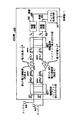
【図6】2個の空間的に離れたアンテナと、本発明の一実施例に基づき電力増幅器を共用可能な送信機の一部分とを示すブロック図である。
【図7】90度ハイブリッド組み合わせ器の一実現例である。
【図8】2個の空間的に離れたアンテナと、本発明の別の実施例に基づき電力増幅器を共用可能な送信機の一部分とを示すブロック図である。
【図9】180度ハイブリッド組み合わせ器の一実現例を示す説明図である。
【図10】電力増幅器の非線形性を補償するために用いられる在来型のフィードフォワード・ループを示すブロック図である。
【図11】2個の空間的に離れたアンテナと、本発明の別の実施例に基づき電力増幅器を共用可能な送信機の一部分とを示すブロック図である。
【図12】ディジタル前置補償器を示すブロック図である。
【図13】2個の空間的に離れたアンテナと、本発明の更に別の実施例に基づき電力増幅器を共用可能な送信機の一部分とを示すブロック図である。
【符号の説明】
100 在来型の無線通信システム
102、104、106 セル
112、114、116 基地局
120 移動交換センタ(MSC)
121 ローカル及び/又は長距離伝送ネットワーク
122、124 移動端末
125 制御器
130 送信機
135 受信機
140 アンテナ
147 チャネル処理回路
150 無線装置
162 信号
164 建物
165 信号
166 山脈
170 電力増幅器
230 送信機
240、245 アンテナ
247 チャネル処理回路
250、255 無線装置
260 信号
265 信号
270、275 電力増幅器
280、285 導線
530 送信機
547 チャネル処理回路
550、555 無線装置
570 第1の電力増幅器
575 第2の電力増幅器
602 第1の入力部
604 第2の入力部
606、608、610、614 部分パス
616 第1の出力部
618 第2の出力部
630 送信機
640、645 アンテナ
647 チャネル処理回路
650、655 無線装置
670 第1の電力増幅器
675 第2の電力増幅器
680、682、685、687 導線
690 増幅器前ハイブリッド組み合わせ器
697 増幅器後ハイブリッド組み合わせ器
702 第1の入力部
704 第2の入力部
706、708、711、714 部分パス
710、715 フィードフォワード・ループ
716 第1の出力部
718 第2の出力部
720、725 補正増幅器
721、722、724、726、727、729 導線
730 送信機
732、733、737、738 遅延回路
734、739 結合器
752、757 回路
790 増幅器前ハイブリッド組み合わせ器
797 増幅器後ハイブリッド組み合わせ器
810 回路
812 ルックアップテーブル
820 第1のディジタル前置補償器
825 第2のディジタル前置補償器
830 送信機
850、855 無線装置
860、865 RF部(変調器)
890 第1の増幅器前ハイブリッド組み合わせ器
895 第2の増幅器前ハイブリッド組み合わせ器
930 送信機
950、955 無線装置
990 第1の増幅器前ハイブリッド組み合わせ器
995 第2の増幅器前ハイブリッド組み合わせ器[0001]
BACKGROUND OF THE INVENTION
The present invention relates to effective use of amplifier power capacity in a wireless communication system having, for example, transmission diversity.
[0002]
[Prior art]
In a wireless communication system, a geographic area is divided into a plurality of spatially distinct areas called “cells”. Each cell has a base station with equipment for communicating with a mobile switching center (MSC). The mobile switching center is connected to a local and / or long distance transmission network such as a public switched telephone network (PSTN). Each base station also has a wireless device, a power amplifier, and an antenna that each base station uses to communicate with mobile terminals. Each communication session with one specific mobile terminal is called a “call”.
[0003]
As the mobile terminal moves, the strength of the signal from the base station received by the mobile terminal varies. This variation is due to various factors, such as the distance of the mobile terminal from the base station, the destructive interference due to so-called out of phase multipath, and the signal path from the base station to the mobile terminal. Includes the presence of obstacles (like buildings). This phenomenon is called fading. One way to deal with fading is by a technique known as transmit diversity.
[0004]
Transmit diversity consists of a technique in which one signal is transmitted on at least two antennas that are spatially separated. When two antennas are used, the signal is processed using two separate coding sequences to generate two diversity coded signals (hereinafter referred to as diversity coded signals), and these diversity coded signals. Are amplified in one of the two power amplifiers and transmitted from one of the two antennas.
[0005]
Since the diversity encoded signal is transmitted from spatially separated antennas, the fading of these two diversity encoded signals is different from each other. As a result, it is possible to reduce the combination value (combination transmission power) of the transmission power of these diversity coded signals without degrading the quality of the signal received at the mobile terminal. In general, a gain of 3 dB is achieved when transmit diversity is used. This means that the combined transmission power of two diversity encoded signals directed to one mobile terminal among a plurality of mobile terminals is reduced to about ½ of the transmission power of a signal transmitted without using transmission diversity. It is possible to do this without affecting the quality of the communication.
[0006]
By reducing the transmission power, it is possible to increase the number of signals that can be transmitted simultaneously, and thus increase the capacity of the wireless communication system (the capacity of the wireless communication system (or simply the system capacity) The number of calls that can be carried simultaneously by the wireless communication system). This increase in system capacity can be achieved without increasing the total power capacity of the power amplifier. Here, the power capacity of the power amplifier means the maximum value of the output power level when the power amplifier is designed to operate at a certain output power level for a considerable length of time.
[0007]
Since there are two power amplifiers, one for each of these two diversity coded signals, the power capacity of each power amplifier in a wireless communication system (simply diversity system) using transmit diversity is When the power capacity of the power amplifier of the “non-diversity system” (wireless communication system not using transmission diversity) is ½, the total power capacity of the power amplifier of the diversity system is the power used for the non-diversity system. It is the same as the power capacity of the amplifier.
[0008]
On the other hand, the transmit power reduction obtained by using transmit diversity reduces the power capacity of each of these two power amplifiers to about 1/4 of the power capacity of a non-diversity system power amplifier having the same system capacity. It becomes possible to do.
[0009]
In order to obtain the benefits of transmission diversity, the mobile terminal needs to have diversity support capability, that is, diversity support. That is, when two diversity coded signals are received at the mobile terminal, it is necessary to design the mobile terminal so that the two diversity coded signals can be processed and combined. If the mobile terminal does not have diversity support capability, that is, it does not support diversity, it cannot process and combine the diversity encoded signals. Currently, most mobile terminals do not support diversity. Therefore, it is advantageous if the base station can communicate with diversity-capable mobile terminals and non-diversity-capable terminals.
[0010]
When defining what kind of power capacity is required for one of the two amplifiers of the base station, two cases (cases) can be considered. In the first case, the base station is in full load and is only communicating with non-diversity mobile terminals. In this case, all signals are amplified by one of the power amplifiers of the base station, for example, the first power amplifier, and transmitted from one antenna. Therefore, the power capacity of the first power amplifier needs to be large enough to amplify all signals, while maintaining at least the same capacity as that of the non-diversity system.
[0011]
In the second case, the base station is in a full load state and is only communicating with a diversity-enabled mobile terminal. In this case, each of the signals is encoded to generate two diversity encoded signals, each of which is amplified in each one of the two power amplifiers. Therefore, the second power amplifier can be smaller than the first power amplifier. This is because, as described above, the power of a signal transmitted using transmission diversity is smaller than the power of a signal transmitted without using transmission diversity. However, the second power amplifier still needs to be large enough to amplify one of the two diversity encoded signals to each mobile terminal.
[0012]
[Problems to be solved by the invention]
One problem with the above base station is that at least one (and usually both) of the two power amplifiers is not fully utilized for most of the time (underutilized). If all of the mobile terminals communicating with the base station do not support diversity, all signals transmitted from the base station to the mobile terminals are amplified by the first power amplifier, and the second power amplifier remains unused. .
[0013]
If any of the mobile terminals in communication with the base station is diversity capable, the signal to these mobile terminals is amplified by both power amplifiers. If the second power amplifier is smaller than the first power amplifier, the first power amplifier is underutilized and therefore at least one of the two power amplifiers is always underutilized. It is in the state of.
[0014]
If the second power amplifier is the same size as the first power amplifier, the first power amplifier is not underutilized, but this time the second power amplifier will have a much larger power capacity, If none of the mobile terminals are non-diversity mobile terminals, all of this (second power amplifier) power capacity is wasted and wasted (in this case, some of the mobile terminals are not diversity). If it is compliant and some others are non-diversity, a significant portion of the power capacity of this power amplifier is wasted).
[0015]
Because the cost of a power amplifier is directly proportional to its power capacity and the power amplifiers used in these types of applications are very expensive (generally, the total cost of the base station is 15% to 25%), the above The waste of power capacity in both cases can be substantial.
[0016]
Therefore, it is required to obtain a base station that can communicate with a diversity-compatible mobile terminal and a non-compatible mobile terminal so that its power amplifier can be used more fully.
[0017]
[Means for Solving the Problems]
The present invention solves the above problems by sharing an amplifier in a system designed to utilize transmit diversity. In this case, the amplifier is 1) first and second diversity encoded signals, each of which is encoded by the first signal to be transmitted using transmission diversity. Shared to amplify the diversity encoded signal as represented, and 2) to amplify the second signal to be transmitted without transmit diversity.
[0018]
In one embodiment of the invention, the first and second diversity encoded signals are used to form the first and second composite signals. Each of these composite signals is amplified in a separate power amplifier of the two power amplifiers. Each of the amplified composite signals is then used to form an amplified first diversity encoded signal and an amplified second diversity encoded signal. Optionally, the amplified first diversity encoded signal and the amplified second diversity encoded signal may be converted into an amplified first diversity encoded signal phase-shifted version and an amplified second diversity encoded signal. It is also possible to use a signal phase-shifted version (a signal obtained by phase shifting (phase-shifting) the first diversity coded signal is referred to as “first diversity coded signal phase-shifted version”).
[0019]
The first and second composite signals can also be formed using the second signal. Each of these composite signals is then amplified in a separate power amplifier of the two power amplifiers (670 and 675), and using these two amplified composite signals, an amplified second signal is obtained. It is formed. In this case, the power of each composite signal is only ½ of the power of the second signal. As a result, the power capacity of each power amplifier of the two power amplifiers of the diversity system can be ½ of the power capacity of the power amplifier of the non-diversity system having the same system capacity.
[0020]
Thus, when a signal is transmitted without transmit diversity, both power amplifiers are utilized, reducing the power capacity waste and associated costs of the power amplifier. In addition, since the power amplifiers used have the same size, when transmission diversity is used, the power of the composite signal is ½ of the sum of the power of the first and second diversity encoded signals. This power amplifier is also more fully utilized.
[0021]
DETAILED DESCRIPTION OF THE INVENTION
In the conventional wireless communication system 100 shown in FIG. 1, the geographical area is divided into a plurality of
[0022]
FIG. 2 shows the
[0023]
[0024]
A
[0025]
As the
[0026]
In addition, a multipath of
[0027]
When the multipath of the
[0028]
The sum of the
[0029]
One way to deal with fading is by a technique known as transmit diversity. Transmit diversity relates to the ability to transmit multiple diversity encoded duplicate signals of one signal over a channel having uncorrelated fading characteristics. A diversity-encoded version of the signal (diversity-encoded signal) can be generated using the diversity code and encoding sequence described below.
[0030]
Transmit diversity means spatial diversity, that is, a method of transmitting diversity encoded signals from spatially separated antennas, or time diversity, that is, a method of transmitting diversity encoded signals at different time intervals, or polarization diversity. That is, it can be realized using a technique of transmitting a diversity encoded signal from two antennas having different polarization planes, or other types of diversity. For convenience of explanation, the description will be made using a spatial diversity technique, but any diversity technique can be used.
[0031]
FIG. 3 shows a transmitter 230 coupled to two
[0032]
The diversity encoded signals are each fed to a separate wireless device of the two
[0033]
Since the diversity encoded signal is transmitted from spatially separated antennas, the fading of these two diversity encoded signals is different from each other. For example, FIG. 4 shows a
[0034]
In this way, since the diversity coded signals are transmitted from the spatially separated
[0035]
This can reduce the combined transmission power of the two diversity encoded signals directed to the
[0036]
Since the combined transmission power of the two diversity coded signals directed to the
[0037]
Since there are two power amplifiers (270, 275), the power capacity of each power amplifier in the diversity system is 1/2 of the power capacity P of the
[0038]
The base station with transmitter 230 is advantageous if all the mobile terminals are diversity capable. This means that when two diversity coded signals are received at the mobile terminal, the mobile terminal is designed so that the mobile terminal can process and combine these two diversity coded signals. . Currently, most mobile terminals do not support diversity. Therefore, it is advantageous if the base station can communicate with diversity-capable mobile terminals and non-diversity-capable terminals.
[0039]
FIG. 5 shows a
[0040]
When the
[0041]
When
[0042]
In a base
[0043]
If any of the mobile terminals in communication with
[0044]
If the
[0045]
FIG. 6 shows a transmitter 630 and
[0046]
The operation of one embodiment of the transmitter 630 will be described below. When the transmitter 630 is communicating with a diversity-enabled mobile terminal, the first signal is supplied from the controller to the
[0047]
The
[0048]
These two diversity encoded signals are orthogonal to each other. This avoids a situation in which destructive interference occurs when these two diversity coded signals are received at the mobile terminal. These two diversity encoded signals can be made orthogonal by using first and second encoding sequences that are orthogonal to each other. For example, in a CDMA communication system, these two coding sequences are two different Walsh codes. (Walsh codes are orthogonal coding sequences used to encode signals at the transmitter so that several signals can share the same bandwidth.)
[0049]
The two diversity encoded signals are supplied to the signal S at the input of the pre-amplifier hybrid combiner 690.1And S2Used as Therefore, in this case, the signal S1Is the first diversity coded signal, and the signal S2Is the second diversity coded signal. A pre-amplifier hybrid combiner 690 uses each diversity encoded signal to form first and second composite signals.
[0050]
Hereinafter, an embodiment of the first and second composite signal formation will be described. Here, each composite signal has information represented by each of the two diversity encoded signals. The pre-amplifier hybrid combiner 690 is "S11st and 2nd representation signals "(signal S1The first and second signals representing the information represented by1Are referred to as first and second expression signals). Each of these representation signals is S1, But the power it has is
[0051]
The first and second composite signals are then amplified by first and
[0052]
A post-amplifier
[0053]
One of the amplified diversity encoded signals is transmitted from the
[0054]
Returning to the pre-amplifier hybrid combiner, the pre-amplifier hybrid combiner 690 may be any hybrid combiner. In the illustrated example, the pre-amplifier hybrid combiner 690 is a conventional hybrid combiner that is easy to produce, such as a 90-degree hybrid combiner. As described in more detail below, the pre-amplifier hybrid combiner 690 includes S1Two representation signals of the same power for S and S2And two representation signals of the same power for. As a result, the power of each representation signal is ½ of the power of the diversity encoded signal, and the voltage of each representation signal is 1 / (2 of the voltage of the diversity encoded signal.1/2) It becomes.
[0055]
When the pre-amplifier hybrid combiner 690 is a 90-degree hybrid combiner, the pre-amplifier hybrid combiner 690 shifts the phase of one expression signal of two expression signals of each diversity encoded signal by 90 degrees. However, the other representation signal does not shift in phase,
(1 / (21/2)) S1And [(1 / (21/2)) S1]90degWhen,
(1 / (21/2)) S2And [(1 / (21/2)) S2]90degAnd
Generate. Where [x]90degRepresents “x shifted by 90 degrees”. In the drawing, “x shifted by 90 degrees” is expressed by using “a sign obtained by drawing a double line above x”.
[0056]
S1Of the expression signal (1 / (21/2)) S1, S2Of the phase-shifted representation signal [(1 / (21/2)) S2]90degTo the first composite signal, (1 / (21/2)) S1+ [(1 / (21/2)) S2]90degIs formed. S2Of the expression signal (1 / (21/2)) S2, S1Of the phase-shifted representation signal [(1 / (21/2)) S1]90degTo the second composite signal, (1 / (21/2)) S2+ [(1 / (21/2)) S1]90degIs formed.
[0057]
Accordingly, the first composite signal is a function of the combination of the first diversity coded signal and the second diversity coded signal phase shift version, and the second composite signal is the second diversity coded signal and the first diversity signal. It is a function of the combination with the diversity coded signal phase shift version.
[0058]
FIG. 7 shows details of one implementation of the pre-amplifier hybrid combiner 690. The pre-amplifier hybrid combiner 690 has its first and
[0059]
S1When S enters the microstrip path, S1Is two representation signals, (1 / (21/2)) S1And (1 / (21/2)) S1And the first expression signal starts to travel on the
[0060]
S2The first expression signal passes through the partial path 608 to the junction point of the
[0061]
S1The second expression signal passes through the partial path 608 to the junction point of the partial paths 608 and 610. As a result, S1The phase of the second expression signal is shifted (shifted) by 90 degrees. At the junction of partial paths 608 and 610, S1Of the second representation signal phase-shifted version [(1 / (21/2)) S1]90degIs S2Of the second representation signal (1 / (21/2)) S2Combined with the second composite signal (1 / (21/2)) S2+ [(1 / (21/2)) S1]90degIs formed. The second composite signal proceeds to the
[0062]
The first composite signal is then amplified in the
[0063]
Note that the power of each of the first and second composite signals is S1To 1/2 of the power of S2Is added to half of the power. That is, the power of each composite signal is ½ of the sum of the powers of the first and second diversity encoded signals, which is ½ of the power of the first signal. Thus, only half of the power of the first signal is amplified in one of these amplifiers.
[0064]
Two amplified composite signals (1 / (21/2)) AS1+ [(1 / (21/2)) AS2]90degAnd [(1 / (21/2)) AS1]90deg+ (1 / (21/2)) AS2Is supplied to the post-amplifier hybrid combiner 697 (A is the gain of the amplifier). As described above, post-amplifier
[0065]
(Note that for the purposes of the present invention, it is not important whether the amplified and diversity encoded signals are in phase or out of phase. However, for certain applications, If it is advantageous if the phases of the amplified and diversity encoded signals are in phase, this can be done by incorporating this matching condition in the design of the transmitter, eg below. (As described, the pre-amplifier hybrid combiner and the post-amplifier hybrid combiner are 180-degree combiners.)
[0066]
If the pre-amplifier hybrid combiner 690 is a 90-degree hybrid combiner, the post-amplifier
[0067]
A post-amplifier
[0068]
The power of the second composite signal is also S1Power of ((1/2) A)2Multiplied by the value S2Power of ((1/2) A)2The value multiplied by is added. Therefore, the voltage of each representation signal of the amplified second composite signal is also S1The value obtained by multiplying the voltage of (1/2) A by S2Is obtained by adding a value obtained by multiplying the voltage of (1/2) A.
[0069]
After forming the expression signal, the post-amplifier
A non-phase-shifted (non-phase-shifted) representation signal of the amplified first composite signal,
(1/2) AS1+ [(1/2) AS2]90deg(1)
A representation phase-shifted version of the amplified first composite signal,
[(1/2) AS1]90deg+ [(1/2) AS2]180deg(2)
(Where [x]980degRepresents “x shifted by 180 degrees”. In the drawing, “x shifted by 180 degrees” is expressed by using “a sign obtained by drawing a single line above x”. )
A non-phase-shift representation signal of the amplified second composite signal;
[(1/2) AS1]90deg+ (1/2) AS2 (3) and
A representation signal phase-shifted version of the amplified second composite signal,
[(1/2) AS1]180deg+ [(1/2) AS2]90deg(4),
Is generated.
[0070]
The amplified first composite signal non-phase-shifted representation signal is added to the amplified second composite signal representation signal phase-shifted version to obtain the next signal;
(1/2) AS1+ [(1/2) AS2]90deg
+ [(1/2) AS1]180deg+ [(1/2) AS2]90deg
= (1/2) AS1+ [(1/2) AS2]180deg+ [AS2]90deg(5)
Is generated at the first output of the post-amplifier
[0071]
(1/2) AS1+ [(1/2) AS2]180degIs equal to zero, so equation (5) becomes [AS2]90degWhich is the amplified (and phase-shifted) second diversity encoded signal. Thus, the amplified second diversity encoded signal is formed from the amplified first and second composite signals. Specifically, in this case, the amplified first diversity encoded signal is a function of the combination of the first composite signal and the phase-shifted version of the second composite signal.
[0072]
This amplified second diversity encoded signal is then transmitted via
[0073]
The amplified second composite signal non-phase-shifted representation signal is added to the amplified first composite signal representation signal phase-shifted version to produce the following signal:
[(1/2) AS1]90deg+ (1/2) AS2
+ [(1/2) AS1]90deg+ [(1/2) AS2]180deg
= [AS1]90deg+ (1/2) AS2+ [(1/2) AS2]180deg(6)
Is generated at the second output of the post-amplifier
[0074]
(1/2) AS2+ [(1/2) AS2]180degIs equal to zero, so equation (6) becomes [AS1]90degWhich is an amplified (and phase-shifted) first diversity encoded signal. Thus, the amplified first diversity encoded signal is formed as a function of the amplified first and second composite signals. Specifically, in this case, the amplified first diversity encoded signal is a function of a combination of the second composite signal and a phase-shifted version of the first composite signal.
[0075]
This amplified first diversity encoded signal is then transmitted via
[0076]
When the transmitter 630 is communicating with a non-diversity mobile terminal, the operation of the transmitter 630 is the same as that when communicating with a diversity mobile terminal except for the following points. That is, a signal to be transmitted to the mobile terminal (hereinafter referred to as a second signal) is not duplicated using the diversity code but is encoded by the
[0077]
This second (encoded) signal is the signal S at the first input of the pre-amplifier hybrid combiner 690.1Since there is no signal at the second input of the pre-amplifier hybrid combiner 690, S1= Second signal and S2= 0. S2= 0, the first composite signal is (1 / (21/2)) S1And the second composite signal is [(1 / (21/2)) S1]90degIt becomes. That is, in this case, the first and second composite signals are functions of the second signal. The first composite signal is amplified in the
[0078]
Therefore, in this case, only 1/2 of the second signal is amplified in each of the power amplifiers. This means that the power level of the signal passing through each power amplifier is ½ of the power of all signals, and thus, 1 of the power capacity P of the
[0079]
S2If = 0, there is no signal at the first output of the post-amplifier
[0080]
At any particular point in time, transmitter 630 can be in communication with a diversity-enabled mobile terminal, a non-diversity-enabled mobile terminal, or both. Accordingly, (1) the transmitter 630 shares the amplification processing of the first and second diversity encoded signals between the first and
[0081]
<< Amplifier sharing with 180-degree hybrid combiner >>
The case where the pre-amplifier hybrid combiner and the post-amplifier hybrid combiner of the transmitter 630 are 90-degree hybrid combiners has been described above. As described above, the hybrid combiner supplies the amplified first diversity encoded signal to one of the two antennas, and supplies the amplified second diversity encoded signal to the other of the two antennas. As long as it is possible, any kind of hybrid combiner may be used. For example, both hybrid combiners may be 180 degree hybrid combiners.
[0082]
FIG. 8 shows the operation of the transmitter 730 when the
[0083]
The
(1 / (21/2)) S1+ (1 / (21/2)) S2 (7)
Thus, the first composite signal is a function of the sum of the first diversity encoded signal and the second diversity encoded signal.
[0084]
The
(1 / (21/2)) S1-(1 / (21/2)) S2 (8)
Thus, the second composite signal is a function of the difference between the first diversity encoded signal and the second diversity encoded signal.
[0085]
FIG. 9 shows details of one implementation of the
The
[0086]
S1When S enters the microstrip path, S1Are split into two representation signals, with the first representation signal proceeding on the
[0087]
S1And S2Of the first representation signal (1 / (21/2)) S1And (1 / (21/2)) S2Respectively proceed through
[0088]
The first composite signal is amplified in the
[0089]
A post-amplifier
[0090]
The power of the second composite signal is also S1Power of ((1/2) A)2Multiplied by the value S2Power of ((1/2) A)2The value multiplied by is added. Therefore, the voltage of each representation signal of the amplified second composite signal is also S1The value obtained by multiplying the voltage of (1/2) A by S2Is obtained by adding a value obtained by multiplying the voltage of (1/2) A.
[0091]
The post-amplifier
(1/2) AS1+ (1/2) AS2
+ (1/2) AS1-(1/2) AS2 = AS1 (9)
Is an amplified first diversity encoded signal. Thus, the amplified first diversity encoded signal is formed as a function of the sum of the amplified first composite signal and the amplified second composite signal. This amplified first diversity encoded signal is then transmitted via
[0092]
The post-amplifier
(1/2) AS1+ (1/2) AS2
-[(1/2) AS1-(1/2) AS2]
= (1/2) AS1+ (1/2) AS2
-(1/2) AS1+ (1/2) AS2] = AS2 (10)
AS2Is the amplified second diversity encoded signal. Thus, the amplified second diversity encoded signal is a function of the difference between the amplified first composite signal and the amplified second composite signal. This amplified second diversity encoded signal is then transmitted to the mobile terminal via
[0093]
When the transmitter 730 is communicating with a non-diversity mobile terminal, a signal to be transmitted to the mobile terminal (hereinafter referred to as a second signal) is the
[0094]
The first composite signal is amplified in the
[0095]
To explain with reference to equations (9) and (10), S2= 0, the first output of the post-amplifier
[0096]
<< Amplifier sharing with digital pre-compensation >>
An important goal in prior art amplifier sharing arrangements is to avoid situations where the phase and gain of the
[0097]
Advantageously,
[0098]
In feed
[0099]
Circuit 752 isolates distortion in the first composite signal produced by power amplifier 670 (this separation is generally accomplished by comparing the amplified first composite signal with a function of the signal on lead 721). The distortion value is supplied to the
[0100]
A
[0101]
Using
[0102]
FIG. 11 shows a
[0103]
Based on the idea that the prior art is formed in the analog domain to avoid situations where the phase and gain of the wireless device must be matched to obtain an acceptable antenna separation limit, as described above. Yes. However, the Applicant has recognized that in systems where amplifiers are shared, the advantages of digital pre-compensation can more than compensate for these problems. The digital pre-compensation signal amplified in the shared amplifier compensates for the non-linearity of the amplifier without the cost, inefficiency, and potential for high circuit failure of the analog feedforward loop.
[0104]
A
[0105]
Hereinafter, the operation of the
[0106]
A digital signal is expressed in terms of its real component I and quadrant component Q (Q is sometimes also referred to as an imaginary component). Therefore, the first diversity coded signal S1Is (I1, Q1) And the first diversity coded signal S2Is (I2, Q2) Can be expressed as
[0107]
Similar to the analog pre-amplifier hybrid combiner, the digital pre-amplifier hybrid combiner 890, 895 may be any type of hybrid combiner. When the pre-amplifier hybrid combiner 890, 895 is a 90-degree hybrid combiner, the first pre-amplification hybrid combiner 890 is S1And S2Of the first representation signal. Each of these representation signals is a respective diversity encoded signal (S1Or S2) Represents the same information as that represented by.
[0108]
The second pre-amplification hybrid combiner 895 is S1And S2Of the second expression signal. Each of these representation signals is a respective diversity encoded signal (S1Or S2) Represents the same information as that represented by. The power of each expression signal is ½ of the power of the diversity encoded signal, and the voltage of each expression signal is 1 / (2 of the voltage of the diversity encoded signal.1/2) It becomes.
[0109]
Therefore, the first pre-amplification hybrid combiner 890 has S1To the representation signal ((1 / (21/2)) I1, (1 / (21/2)) Q1) And S2To the representation signal ((1 / (21/2)) I2, (1 / (21/2)) Q2), And the second pre-amplification hybrid combiner 895 has S1To the representation signal ((1 / (21/2)) I1, (1 / (21/2)) Q1) And S2To the representation signal ((1 / (21/2)) I2, (1 / (21/2)) Q2) Respectively.
[0110]
Each pre-amplification hybrid combiner 890, 895 then shifts one of the two representation signals by 90 degrees, does not phase shift the other representation signal, and combines the non-phase-shift representation signal with the representation signal phase-shifted version. , Forming a composite signal. A 90 degree phase shift of the signal can be achieved by exchanging the values of the real and quadrant components. Therefore, after the phase shift, S1The expression signal of ((1 / (21/2)) I1, (1 / (21/2)) Q1) And (-(1 / (21/2)) Q1, (1 / (21/2)) I1) And S2The expression signal of ((1 / (21/2)) I2, (1 / (21/2)) Q2) And (-(1 / (21/2)) Q2, (1 / (21/2)) I2)
[0111]
The first pre-amplification hybrid combiner 890 has S1Non-phase-shift expression signal ((1 / (21/2)) I1, (1 / (21/2)) Q1) S2Expression signal phase-shifted version (-(1 / (21/2)) Q2, (1 / (21/2)) I2) To the first composite signal ((1 / (21/2)) I1-(1 / (21/2)) Q2, (1 / (21/2)) Q1+ (1 / (21/2)) I2). The second pre-amplification hybrid combiner 895 has S2Non-phase-shift expression signal ((1 / (21/2)) I2, (1 / (21/2)) Q2) S1Expression signal phase-shifted version (-(1 / (21/2)) Q1, (1 / (21/2)) I1) To the second composite signal ((1 / (21/2)) I2-(1 / (21/2)) Q1, (1 / (21/2)) Q2+ (1 / (21/2)) I1).
[0112]
Digital precompensation is then performed on the composite signal. FIG. 12 shows the first digital predistorter 820 in detail. A digital precompensator determines the power of the first composite signal in
[0113]
The RF unit 860 of the wireless device 850 then modulates the first composite signal into an RF signal, and the
[0114]
Note that the power of each of the first and second composite signals is S1To 1/2 of the power of S2Is added to half of the power. That is, the power of each of the first and second composite signals is ½ of the sum of the powers of the first and second diversity encoded signals, which is the first signal received from the transmission circuit. 1/2 of the power. Thus, only 1/2 of the first signal is amplified in each of the amplifiers.
[0115]
Two amplified composite signals ((1 / (21/2)) AI1-(1 / (21/2)) AQ2, (1 / (21/2)) AQ1+ (1 / (21/2)) AI2) And ((1 / (21/2)) AI2-(1 / (21/2)) AQ1, (1 / (21/2)) AQ2+ (1 / (21/2)) AI1Is supplied to the post-amplifier
[0116]
If pre-amplifier hybrid combiners 890 and 895 are 90-degree hybrid combiners, post-amplifier
[0117]
The post-amplifier
[0118]
The power of the first composite signal is S1Power of ((1/2) A)2Multiplied by the value S2Power of ((1/2) A)2The value multiplied by is added. Therefore, the voltage of each representation signal of the amplified first composite signal is S1The value obtained by multiplying the voltage of (1/2) A by S2Is obtained by adding a value obtained by multiplying the voltage of (1/2) A. The power of the second composite signal is also S1Power of ((1/2) A)2Multiplied by the value S2Power of ((1/2) A)2The value multiplied by is added. Therefore, the voltage of each representation signal of the amplified second composite signal is S1The value obtained by multiplying the voltage of (1/2) A by S2Is obtained by adding a value obtained by multiplying the voltage of (1/2) A.
[0119]
After forming the expression signal, the post-amplifier
A non-phase-shift representation signal of the amplified first composite signal;
((1/2) AI1-(1/2) AQ2, (1/2) AQ1+ (1/2) AI2) (11)
A representation phase-shifted version of the amplified first composite signal,
(-(1/2) AQ1-(1/2) AI2, (1/2) AI1-(1/2) AQ2(12)
A non-phase-shift representation signal of the amplified second composite signal;
((1/2) AI2-(1/2) AQ1, (1/2) AQ2+ (1/2) AI1) (13)
And a signal phase-shifted version of the amplified second composite signal,
(-(1/2) AQ2-(1/2) AI1, (1/2) AI2-(1/2) AQ1(14)
Is generated.
[0120]
The amplified first composite signal non-phase-shifted representation signal is added to the amplified second composite signal representation signal phase-shifted version, and the next signal is the first output of the post-amplifier
([(1/2) AI1-(1/2) AQ2] + [-(1/2) AQ2-(1/2) AI1],
[(1/2) AQ1+ (1/2) AI2] + [(1/2) AI2-(1/2) AQ1])
= (-AQ2, AI2(15)
As mentioned above, a 90 degree phase shift of the signal can be achieved by exchanging the values of the real and quadrant components. Therefore, (-AQ2, AI2) Is a phase-shifted amplified version of the second diversity encoded signal. This signal is then transmitted to the mobile terminal via
[0121]
The amplified second composite signal non-phase-shifted representation signal is added to the amplified first composite signal representation signal phase-shifted version, and the next signal is the second output of the post-amplifier
([(1/2) AI2-(1/2) AQ1] + [-(1/2) AQ1-(1/2) AI2],
[(1/2) AQ2+ (1/2) AI1] + [(1/2) AI1-(1/2) AQ2])
= (-AQ1, AI1(16)
(-AQ1, AI1) Is a phase-shifted amplified version of the first diversity encoded signal. This signal is then transmitted via
[0122]
When the
[0123]
S2 = 0, the first composite signal is ((1 / (21/2)) I1, (1 / (21/2)) Q1) And the second composite signal is (-(1 / (21/2)) Q1, + (1 / (21/2)) I1) Thus, the first and second composite signals are a function of the second signal. The RF unit 860 of the wireless device 850 then modulates the first composite signal into an RF signal, and the
[0124]
The resulting first composite signal is amplified in
[0125]
S2If = 0, there is no signal at the first output of the post-amplifier
[0126]
In order for the amplified first and second diversity encoded signals to be accurately obtained by the post-amplifier hybrid combiner, the RF section of the wireless device 850, 855 is obtained so as to obtain an acceptable antenna separation limit value. 860, 865 need to be phase and gain matched. The antenna separation limit is the ratio of the power of all signals that are not designed to be transmitted from an antenna to the power of signals that are designed to be transmitted from that antenna.
[0127]
For example, if the antenna separation limit value is equal to or smaller than 20 dB, it can be said that the antenna separation limit value is acceptable. In order to obtain an antenna separation limit value of 20 dB, it is necessary to match the phases of the
[0128]
By way of example, the applicant proposes that the
[0129]
<< Amplifier sharing with 180-degree hybrid combiner >>
Similar to the analog pre-amplifier hybrid combiner, the digital pre-amplifier hybrid combiner is fed with an amplified first diversity encoded signal to one of the two antennas and an amplified second diversity encoded signal. As long as is supplied to the other of the two antennas. For example, both pre-amplifier hybrid combiners may be 180 degree hybrid combiners. In that case, the post-amplifier hybrid combiner is also a 180-degree hybrid combiner.
[0130]
FIG. 13 shows the operation of the transmitter 930 when the pre-amplifier hybrid combiners 990 and 995 are 180-degree hybrid combiners. When the transmitter 930 is communicating with a diversity-enabled mobile terminal, as described above, the first signal (ie, the signal to be transmitted to the mobile terminal) is supplied to the
[0131]
The pre-amplifier hybrid combiner 990 has S1And S2Of the first representation signal. Each of these first representation signals is a respective diversity encoded signal (S1Or S2It is a signal that represents the same information that is represented by. In addition, the hybrid combination device 995 before the amplifier1And S2Of the second expression signal. Each of these second representation signals is a respective diversity encoded signal (S1Or S2It is a signal that represents the same information that is represented by. The power of each expression signal is ½ of the power of the diversity encoded signal, and the voltage of each expression signal is 1 / (2 of the voltage of the diversity encoded signal.1/2) It becomes.
[0132]
Accordingly, the first pre-amplifier hybrid combiner 990 has S1To the representation signal ((1 / (21/2)) I1, (1 / (21/2)) Q1) And S2To the representation signal ((1 / (21/2)) I2, (1 / (21/2)) Q2) And the second pre-amplifier hybrid combiner 995 is S1To the representation signal ((1 / (21/2)) I1, (1 / (21/2)) Q1) And S2To the representation signal ((1 / (21/2)) I2, (1 / (21/2)) Q2).
[0133]
A first pre-amplifier hybrid combiner 990 outputs a first composite signal. This first composite signal is S1One expression signal of S and S2Is expressed by the following equation.
((1 / (21/2)) I1+ (1 / (21/2)) I2, (1 / (21/2)) Q1+ (1 / (21/2)) Q2)) (17)
That is, the first composite signal is a function of the sum of the first diversity encoded signal and the second diversity encoded signal.
[0134]
A second pre-amplifier hybrid combiner 995 generates a second composite signal. This second composite signal is S1One expression signal of S and S2The difference from one expression signal is expressed by the following equation.
((1 / (21/2)) I1-(1 / (21/2)) I2, (1 / (21/2)) Q1-(1 / (21/2)) Q2)) (18)
Thus, the second composite signal is a function of the difference between the first diversity encoded signal and the second diversity encoded signal.
[0135]
The RF unit 860 of the
[0136]
The modulated first composite signal is then amplified in
[0137]
A post-amplifier
[0138]
The power of the second composite signal is also S1Power of ((1/2) A)2Multiplied by the value S2Power of ((1/2) A)2The value multiplied by is added. Therefore, the voltage of each representation signal of the amplified second composite signal is S1The value obtained by multiplying the voltage of (1/2) A by S2Is obtained by adding a value obtained by multiplying the voltage of (1/2) A.
[0139]
The post-amplifier
([(1/2) AI1+ (1/2) AI2] + [(1/2) AI1-(1/2) AI2],
[(1/2) AQ1+ (1/2) AQ2] + [(1/2) AQ1-(1/2) AQ2])
= (AI1, AQ1(19)
(AI1, AQ1) Is an amplified first diversity coded signal. This signal is then transmitted via
[0140]
The post-amplifier
([(1/2) AI1+ (1/2) AI2]-[(1/2) AI1-(1/2) AI2],
[(1/2) AQ1+ (1/2) AQ2]-[(1/2) AQ1-(1/2) AQ2])
= (AI2, AQ2(20)
(AI2, AQ2) Is the amplified second diversity encoded signal. This signal is then transmitted to the mobile terminal via
[0141]
When the transmitter 930 is communicating with a non-diversity mobile terminal, the operation of the transmitter 930 is the same as that when communicating with a diversity mobile terminal except for the following points. That is, a signal to be transmitted to the mobile terminal (hereinafter referred to as a second signal) is encoded by the
[0142]
S2 = 0, the first composite signal is ((1 / (21/2)) I1, (1 / (21/2)) Q1) And the second composite signal is (-(1 / (21/2)) Q1, + (1 / (21/2)) I1) Thus, the first and second composite signals are a function of the second signal. The RF unit 860 of the
[0143]
The resulting first composite signal is amplified in
[0144]
S2= 0, (AI1, AQ1) Is generated at the first output of the post-amplifier
[0145]
As mentioned above, a transmitter according to an embodiment of the present invention can form a composite signal in either analog or digital domain. For example, the above-described advantages can be obtained by forming a composite signal in the digital domain prior to amplification and precompensating the composite signal using a digital precompensation technique. On the other hand, if a composite signal is formed in the analog domain, for example, the phase and gain of the wireless device can be matched in applications where the digital precompensation technique cannot be used because the signal to be transmitted has a bandwidth greater than 5 MHz. It is possible to avoid the situation that must be made.
[0146]
Then, in applications where the bandwidth of the signal to be transmitted is wider than 5 MHz, it is also advantageous to form the composite signal in the analog domain. Even in embodiments where digital pre-compensation techniques are not used (such as those shown in FIGS. 6 and 8), pre-amplifier hybrid combiners can be implemented in the analog domain, but in these embodiments, The pre-amplifier hybrid combiner will process the signals before the wireless device processes the signals, and the wireless device needs to be phase and gain matched.
[0147]
[0148]
The above description is merely illustrative. That is, for example, in the illustrated embodiment, the shared
[0149]
One advantage of the present invention is that an increase in the power capacity of the shared power amplifier also results in a system capacity increase that is proportionally greater than these power capacity increases. For example, if the shared
[0150]
Further, in the illustrated embodiment, transmit diversity is implemented as having two diversity encoded signals. In another embodiment of the present invention, transmit diversity can be implemented as having more than two diversity encoded signals. When a plurality of diversity encoded signals are used to realize transmission diversity, one power amplifier is provided for each of the diversity encoded signals (and, when spatial diversity is used, the diversity encoded signal is provided). One antenna for each of these).
[0151]
The first signal is duplicated using a diversity code and encoded using an encoding sequence to generate a diversity encoded signal. Each diversity encoded signal is processed by one or more pre-amplifier hybrid combiners to produce a plurality of composite signals that are amplified by a power amplifier. The amplified composite signal is then processed by a post-amplifier hybrid combiner to output one amplified version of the diversity encoded signal on each antenna.
[0152]
In addition, in the exemplary embodiment of the present invention, transmission diversity is realized by transmitting a signal from the base station to the mobile terminal using transmission diversity. In another embodiment of the present invention, the mobile terminal can transmit signals to the base station using transmission diversity according to the present invention.
[0153]
Moreover, in the exemplary embodiment of the invention, the power capacities of the two power amplifiers are equal and the signal S1And S2Are divided into representation signals of the same power, and these representation signals form a composite signal. In another embodiment of the invention, the power capacities of the two power amplifiers are not equal and the powers of the two representation signals are not equal. The ratio of the power of the two representation signals is equal to the ratio of the power capacities of the two power amplifiers. The power ratio of each representation signal of the amplified composite signal is also equal to the power capacity ratio of the two power amplifiers.
[0154]
Furthermore, in the exemplary embodiment of the present invention, the radio device and the channel processing circuit have specific configurations. In other embodiments of the present invention, the wireless device and the channel processing circuit may be configured in any manner. As a first example, the functions of the
[0155]
As a third example, the function performed in the digital domain has been described as being performed in a separate circuit (for example, a channel processing circuit, a pre-amplifier hybrid combiner, and a digital pre-compensator). Can be used to perform some or all of these functions.
[0156]
In addition, in some exemplary embodiments (eg, the embodiments shown in FIGS. 6 and 8), the wireless device and the pre-amplifier hybrid combiner can be separately implemented on separate functional blocks or on the same circuit board. It was explained as a functional element. In these embodiments, the wireless device, channel processing circuit, and pre-amplifier hybrid combiner form a first device. In another exemplary embodiment, the pre-amplifier hybrid combiner can be part of a wireless device, and thus the first device will consist solely of the wireless device and channel processing circuitry.
[0157]
Further, in the exemplary embodiment, all of the signals are to be transmitted at the same frequency, but in other embodiments, the signals can be transmitted at different frequencies. For example, the amplified diversity encoded signal is transmitted at one frequency, and the amplified second signal is transmitted at another frequency. Alternatively, a certain signal of the amplified diversity coded signal and the amplified second signal is transmitted at one frequency, and another of the amplified diversity coded signal and the amplified second signal is transmitted. Are transmitted at different frequencies.
[0158]
Moreover, in the exemplary embodiment, the sharing of the amplifier has been described in an application that supports signal transmission with transmit diversity and signal transmission without transmit diversity, but in another embodiment, digital pre-compensation. Can be used in another application, for example, an application in which an amplifier is shared between two so-called sectors of a cell of a wireless communication system. In addition, the amplifier sharing approach with digital pre-compensation can be used in applications that only support signal transmission with transmit diversity or in applications that support only signal transmission without transmit diversity.
[0159]
Furthermore, while the present invention has been described in connection with the sharing of power amplifiers in an exemplary embodiment, in other embodiments of the invention, the shared amplifier can be any amplifier. In that case, the wireless device's ability to convert a digital signal into an analog RF signal may not be useful in the implementation of such an embodiment of the present invention.
[0160]
In addition, those of ordinary skill in the art will recognize that although each cell is generally a sector in the exemplary embodiment, the cell can be divided into multiple sectors. In this case, the base station includes a radio device, a hybrid combiner, at least two amplifiers, and an antenna for each sector.
[0161]
The above description relates to one embodiment of the present invention, and those skilled in the art can consider various modifications of the present invention, all of which are included in the technical scope of the present invention. The
It should be noted that the reference numerals in the claims are for easy understanding of the invention and should not be construed to limit the technical scope thereof.
[0162]
【The invention's effect】
As described above, according to the present invention, a plurality of power amplifiers are shared for amplification of signals for transmission to mobile terminals in a base station of a radio communication system capable of communicating with transmission diversity compatible mobile terminals and non-compatible mobile terminals. As a result, according to the present invention, the power amplifier can be fully utilized as compared with the case where the power amplifier and the power capacity of the base station are insufficient in the conventional technique. . Therefore, waste of the power capacity of the power amplifier and the associated high cost can be reduced, and the efficiency of the communication system can be increased.
[Brief description of the drawings]
FIG. 1 is an explanatory diagram showing a part of a conventional wireless communication system.
2 is a block diagram showing a part of a base station of the wireless communication system shown in FIG.
FIG. 3 is a block diagram illustrating two spatially separated antennas and a portion of a transmitter capable of transmitting signals using transmit diversity.
4 is an explanatory diagram of a cell of a wireless communication system including a base station including the transmitter of FIG. 3;
FIG. 5 is a block diagram illustrating two spatially separated antennas and a portion of a transmitter capable of signal transmission using transmission diversity and signal transmission without transmission diversity.
FIG. 6 is a block diagram illustrating two spatially separated antennas and a portion of a transmitter that can share a power amplifier according to one embodiment of the present invention.
FIG. 7 is an implementation example of a 90-degree hybrid combiner.
FIG. 8 is a block diagram illustrating two spatially separated antennas and a portion of a transmitter that can share a power amplifier according to another embodiment of the present invention.
FIG. 9 is an explanatory diagram showing an implementation example of a 180-degree hybrid combiner.
FIG. 10 is a block diagram illustrating a conventional feedforward loop used to compensate for power amplifier nonlinearity.
FIG. 11 is a block diagram illustrating two spatially separated antennas and a portion of a transmitter that can share a power amplifier according to another embodiment of the present invention.
FIG. 12 is a block diagram showing a digital predistorter.
FIG. 13 is a block diagram illustrating two spatially separated antennas and a portion of a transmitter that can share a power amplifier according to yet another embodiment of the present invention.
[Explanation of symbols]
100 Conventional wireless communication system
102, 104, 106 cells
112, 114, 116 Base station
120 Mobile Switching Center (MSC)
121 Local and / or long-distance transmission networks
122, 124 Mobile terminal
125 controller
130 Transmitter
135 Receiver
140 Antenna
147 channel processing circuit
150 wireless device
162 signal
164 Building
165 signal
166 Mountain Range
170 Power amplifier
230 Transmitter
240, 245 antenna
247 channel processing circuit
250, 255 wireless device
260 signal
265 signal
270, 275 Power Amplifier
280, 285 conductor
530 transmitter
547 channel processing circuit
550, 555 wireless device
570 first power amplifier
575 Second power amplifier
602 First input unit
604 Second input unit
606, 608, 610, 614 Partial path
616 1st output part
618 second output section
630 transmitter
640, 645 antenna
647 channel processing circuit
650, 655 wireless device
670 First power amplifier
675 Second power amplifier
680, 682, 685, 687 Conductor
690 Hybrid combiner in front of amplifier
697 Hybrid combiner after amplifier
702 First input unit
704 Second input unit
706, 708, 711, 714 Partial path
710, 715 Feed-forward loop
716 first output section
718 second output section
720, 725 Correction amplifier
721, 722, 724, 726, 727, 729
730 transmitter
732, 733, 737, 738 delay circuit
734, 739 coupler
752, 757 circuit
790 Hybrid combiner before amplifier
797 Hybrid combiner after amplifier
810 circuit
812 Look-up table
820 First digital predistorter
825 second digital predistorter
830 transmitter
850, 855 wireless device
860, 865 RF section (modulator)
890 First hybrid combination before amplifier
895 Second hybrid combiner before amplifier
930 transmitter
950, 955 Wireless device
990 First hybrid combiner before amplifier
995 Second hybrid combination device before amplifier
Claims (13)
少なくとも2つの増幅器の間で前記少なくとも第1及び第2のダイバーシチ符号化信号の増幅を分担するステップと、
前記少なくとも2つの増幅器の間で前記第2の信号の増幅を分担するステップと、
前記第2の信号の関数として少なくとも第1及び第2の複合信号の各々を形成するステップとを含み、前記第2の信号の増幅の分担が、
前記第1の複合信号を増幅すること、及び、
前記第2の複合信号を増幅することを含む、方法。The information of the first signal to be transmitted using transmit diversity to amplify at least a first diversity-encoded signal and the No. 2 of diversity code Cassin each represent, is transmitted without using transmit diversity a Rubeki how you amplify the second signal,
A step for dividing responsible amplification of the between at least two amplifiers at least first and second diversity encoded signals,
A step for dividing responsible amplification of the second signal between the at least two amplifiers,
It said second and at least steps of each shape formed of first and second composite signals as a function of the signal, sharing the amplification of the second signal,
Amplifying the first composite signal ; and
It comprises amplifying the second composite signal.
第1の増幅器で前記第1の複合信号を増幅すること、及び、第2の増幅器で前記第2の複合信号を増幅することを含む、請求項1に記載の方法。 Wherein the at least further comprising at least a first and a step that form each of the second composite signal as a function of the first and second diversity encoded signals, the first allocation to step,
Amplifying the first composite signal in a first amplifier, and includes amplifying the second composite signal in a second amplifier The method of claim 1.
前記少なくとも第1及び第2のダイバーシチ符号化信号の関数として少なくとも第1の複合信号と第2の複合信号とを形成するステップと、
増幅された第1の複合信号を生成するために前記第1の複合信号を増幅するステップと、
増幅された第2の複合信号を生成するために前記第2の複合信号を増幅するステップと、
少なくとも前記増幅された第1及び第2の複合信号の関数として、増幅された第1及び第2のダイバーシチ符号化信号を形成するステップとを含み、前記少なくとも第1及び第2のダイバーシチ符号化信号の増幅が少なくとも2つの増幅器の間で分担される、方法。Transmitted the information of the first signal to be transmitted using transmit diversity, each processing the at least a first diversity-encoded signal and the No. 2 of diversity code Cassin express, without using the transmit diversity a way that processes the second signal to,
Wherein the step that form at least a first composite signal and second composite signals as a function of at least first and second diversity encoded signals,
Amplifying said first composite signal to produce an amplified first composite signal;
Amplifying said second composite signal to produce an amplified second composite signal ;
As a function of the first and second composite signal at least the amplified first and second diversity encoded signals amplified and a step that form, the at least first and second diversity encoded even without low amplification of the signal is shared between the two amplification devices, methods.
第1のダイバーシチ符号化信号移相版と第2のダイバーシチ符号化信号移相版とを形成することをさらに含み、
前記増幅された第1のダイバーシチ符号化信号が、増幅された前記第1のダイバーシチ符号化信号移相版をさらに含み、前記増幅された第2のダイバーシチ符号化信号が、増幅された前記第2のダイバーシチ符号化信号移相版をさらに含む、請求項4に記載の方法。 Forming the amplified first and second diversity encoded signals comprises:
Further comprising forming a first diversity-encoded signal phase plate and a second diversity encoded signal phase plate,
The first diversity encoded signal said amplified further comprises the amplified first diversity-encoded signal phase plate, the second diversity encoded signal the amplification, the amplified second The method of claim 4, further comprising : a diversity encoded signal phase shift version.
第1のダイバーシチ符号化信号移相版と第2のダイバーシチ符号化信号移相版とを形成することをさらに含み、
前記第1の複合信号が、前記第1のダイバーシチ符号化信号と前記第2のダイバーシチ符号化信号の移相版との組み合わせの関数であり、前記第2の複合信号が、前記第2のダイバーシチ符号化信号と前記第1のダイバーシチ符号化信号の移相版との組み合わせの関数である、請求項4に記載の方法。 Forming at least the first composite signal and the second composite signal;
Further comprising forming a first diversity-encoded signal phase plate and a second diversity encoded signal phase plate,
The first composite signal is a function of a combination of the first diversity encoded signal and a phase-shifted version of the second diversity encoded signal, and the second composite signal is the second diversity signal. it is a function of the combination of the phase shift version of the encoded signal a first diversity-encoded signal the method of claim 4.
第1のダイバーシチ符号化信号移相版と第2のダイバーシチ符号化信号移相版とを形成することをさらに含み、
前記増幅された第1のダイバーシチ符号化信号が、前記増幅された第1の複合信号と前記増幅された第2の複合信号の移相版との組み合わせの関数であり、前記増幅された第2のダイバーシチ符号化信号が、前記増幅された第2の複合信号と前記増幅された第1の複合信号の移相版との組み合わせの関数である、請求項4に記載の方法。 Forming the amplified first and second diversity encoded signals comprises:
Further comprising forming a first diversity-encoded signal phase plate and a second diversity encoded signal phase plate,
The amplified first diversity encoded signal is a function of a combination of the amplified first composite signal and a phase-shifted version of the amplified second composite signal, and the amplified second diversity encoded signal is a function of the combination of the phase shift version of the first composite signal the amplified second composite signal the amplification method of claim 4.
少なくとも前記増幅された第1及び第2の複合信号の関数として、増幅された第2の信号を形成するステップとをさらに含む、請求項4に記載の方法。Forming the at least first and second composite signals as a function of a second signal ;
As a function of the first and second composite signal at least the amplifying further comprises the steps that form a second signal which has been amplified, The method of claim 4.
前記第1のデバイスに結合された入力部を有する第1の増幅器を備え、前記第1の増幅器が、増幅された第1の複合信号を生成するために前記第1の複合信号を増幅し、さらに、
前記第1のデバイスに結合された入力部を有する第2の増幅器を備え、前記第2の増幅器は、増幅された第2の複合信号を生成するために前記第2の複合信号を増幅し、さらに、
前記第1の増幅器の出力部に結合された第1の入力部と前記第2の増幅器の出力部に結合された第2の入力部とを有する第2のデバイスを備え、前記第2のデバイスは、少なくとも前記増幅された第1及び第2の複合信号の関数として、増幅された第1及び第2のダイバーシチ符号化信号を形成し、前記少なくとも第1及び第2のダイバーシチ符号化信号の増幅が前記第1及び第2の増幅器の間で分担される、送信装置。 Comprising a first device that form at least a first composite signal and second composite signals as a function of at least first and second diversity encoded signals, the first and second diversity encoded signal , representing the second signal to be transmitted without using the information and transmit diversity of the first issue signals to be transmitted using transmit diversity, further,
Comprising a first amplifier for chromatic an input coupled to said first device, said first amplifier, amplifying the first composite signal to produce a first composite signal amplified ,further,
A second amplifier for chromatic an input coupled to said first device, said second amplifier amplifies the second composite signal to produce a second composite signal amplified And
A second device for chromatic and said second input coupled to the output of the first input and the second amplifier coupled to the output of the first amplifier, the second the device, as a function of the first and second composite signal at least the amplified first and second diversity encoded signals amplified by the formation of the at least first and second diversity encoded signals amplification is shared between the front Symbol first and second amplifying device, the transmitting device.
チャネル処理回路と、
少なくとも1個の無線装置と、
前記無線装置の出力部に結合された入力部と、前記第1の増幅器に結合された第1の出力部と、前記第2の増幅器に結合された第2の出力部とを有する第1のハイブリッド組み合わせ器を備え、前記第1のハイブリッド組み合わせ器は前記第1及び第2の複合信号を形成し、
前記第2のデバイスが、前記第1の増幅器に結合された第1の入力部と前記第2の増幅器に結合された第2の入力部とを有する第2のハイブリッド組み合わせ器を含む、請求項11に記載の送信装置。The first device is
A channel processing circuit;
At least one wireless device;
An input unit coupled to said output of the wireless device, the first of chromatic and first output coupled to said first amplifier and a second output coupled to said second amplifier And the first hybrid combiner forms the first and second composite signals ;
The second device includes a second hybrid combiner having a first input coupled to the first amplifier and a second input coupled to the second amplifier. 11. The transmission device according to 11.
前記第1の増幅器は、前記増幅された第1の複合信号を生成するために前記前置補償された第1の複合信号を増幅し、
前記第2の増幅器は、前記増幅された第2の複合信号を生成するために前記前置補償された第2の複合信号を増幅する、請求項11に記載の送信装置。Said first device, said further comprises a digital predistorter for chromatic an output coupled to the first and second amplifiers, the digital predistorter, the said first composite signal first Precompensation with 2 composite signals ,
The first amplifier amplifies the precompensated first composite signal to generate the amplified first composite signal;
The second amplifier amplifies the second composite signal the is pre-distortion to generate a second composite signal the amplified transmission apparatus according to claim 11.
Applications Claiming Priority (2)
| Application Number | Priority Date | Filing Date | Title |
|---|---|---|---|
| US09/631,885 US7054384B1 (en) | 2000-08-04 | 2000-08-04 | Power amplifier sharing in a wireless communication system with transmit diversity |
| US09/631885 | 2000-08-04 |
Publications (3)
| Publication Number | Publication Date |
|---|---|
| JP2002101027A JP2002101027A (en) | 2002-04-05 |
| JP2002101027A5 JP2002101027A5 (en) | 2008-09-18 |
| JP4948717B2 true JP4948717B2 (en) | 2012-06-06 |
Family
ID=24533172
Family Applications (1)
| Application Number | Title | Priority Date | Filing Date |
|---|---|---|---|
| JP2001235155A Expired - Fee Related JP4948717B2 (en) | 2000-08-04 | 2001-08-02 | Signal amplification method and transmitter |
Country Status (9)
| Country | Link |
|---|---|
| US (1) | US7054384B1 (en) |
| EP (1) | EP1191707B1 (en) |
| JP (1) | JP4948717B2 (en) |
| KR (1) | KR100773028B1 (en) |
| CN (1) | CN1337834A (en) |
| AU (1) | AU5771801A (en) |
| BR (1) | BR0103056A (en) |
| CA (1) | CA2352369A1 (en) |
| DE (1) | DE60102882T2 (en) |
Families Citing this family (25)
| Publication number | Priority date | Publication date | Assignee | Title |
|---|---|---|---|---|
| US7423987B2 (en) * | 2001-04-27 | 2008-09-09 | The Directv Group, Inc. | Feeder link configurations to support layered modulation for digital signals |
| US7471735B2 (en) * | 2001-04-27 | 2008-12-30 | The Directv Group, Inc. | Maximizing power and spectral efficiencies for layered and conventional modulations |
| US8005035B2 (en) * | 2001-04-27 | 2011-08-23 | The Directv Group, Inc. | Online output multiplexer filter measurement |
| US7583728B2 (en) * | 2002-10-25 | 2009-09-01 | The Directv Group, Inc. | Equalizers for layered modulated and other signals |
| US7639759B2 (en) * | 2001-04-27 | 2009-12-29 | The Directv Group, Inc. | Carrier to noise ratio estimations from a received signal |
| CA2489569C (en) * | 2002-07-01 | 2012-05-22 | The Directv Group, Inc. | Improving hierarchical 8psk performance |
| TWI279113B (en) * | 2002-07-03 | 2007-04-11 | Hughes Electronics Corp | Method and apparatus for layered modulation |
| FR2842674B1 (en) * | 2002-07-22 | 2005-02-25 | Cit Alcatel | AMPLIFIER SYSTEM FOR SATELLITE |
| ES2398213T3 (en) * | 2002-10-25 | 2013-03-14 | The Directv Group, Inc. | Low complexity layer modulation signal processor |
| US7024166B2 (en) * | 2002-12-18 | 2006-04-04 | Qualcomm, Incorporated | Transmission diversity systems |
| US7031678B2 (en) * | 2003-07-15 | 2006-04-18 | Qualcomm Inc. | Wireless speech and data transmission |
| US7877081B2 (en) | 2003-07-25 | 2011-01-25 | Qualcomm Incorporated | Proxy-encrypted authentication for tethered devices |
| JP2005348116A (en) * | 2004-06-03 | 2005-12-15 | Sharp Corp | Radio communication device |
| JP4774791B2 (en) * | 2005-04-06 | 2011-09-14 | 日立金属株式会社 | High frequency module |
| US7965987B2 (en) | 2005-11-03 | 2011-06-21 | Magnolia Broadband Inc. | Amplifying a transmit signal using a fractional power amplifier |
| EP2244391B1 (en) * | 2009-04-20 | 2012-05-30 | Alcatel Lucent | Method and equipment for transmitting radio signals |
| US9059749B2 (en) * | 2009-10-02 | 2015-06-16 | Sharp Kabushiki Kaisha | Antenna port mode and transmission mode transitions |
| US8768397B2 (en) | 2009-10-02 | 2014-07-01 | Sharp Kabushiki Kaisha | Transmission power control on a wireless communication device for a plurality of regulated bands or component carriers |
| CN103748803B (en) * | 2011-08-23 | 2018-08-28 | 谷歌有限责任公司 | A method of the mobile device for various modes is to Base Transmitter signal |
| RU2563166C1 (en) * | 2014-12-16 | 2015-09-20 | Федеральное государственное бюджетное образовательное учреждение высшего профессионального образования "Рязанский государственный университет имени С.А. Есенина" | Method for real-time information transmission and system therefor |
| EP4072091A1 (en) * | 2016-05-12 | 2022-10-12 | Panasonic Intellectual Property Corporation of America | Apparatus and method for diversity transmission in a wireless communications system |
| US11398852B2 (en) | 2019-06-24 | 2022-07-26 | Qorvo Us, Inc. | Envelope tracking power amplifier apparatus |
| US11437960B2 (en) | 2019-10-29 | 2022-09-06 | Qorvo Us, Inc. | Average power tracking power amplifier apparatus |
| US20240014785A1 (en) * | 2020-12-18 | 2024-01-11 | Qorvo Us, Inc. | Signal processing apparatus and related transceiver circuit |
| CN114639948B (en) * | 2022-03-21 | 2023-07-04 | 智道网联科技(北京)有限公司 | Antenna for V2X device, V2X device and vehicle |
Family Cites Families (14)
| Publication number | Priority date | Publication date | Assignee | Title |
|---|---|---|---|---|
| JPS63190411A (en) * | 1987-02-02 | 1988-08-08 | Nippon Telegr & Teleph Corp <Ntt> | Power amplifier |
| JPH077883B2 (en) * | 1989-07-11 | 1995-01-30 | 幸弘 豊田 | Push-pull amplifier |
| TW280064B (en) | 1994-09-29 | 1996-07-01 | Radio Frequency Systems Inc | |
| JPH08154015A (en) * | 1994-09-30 | 1996-06-11 | Toshiba Corp | Multibeam power feeding device |
| US5646631A (en) | 1995-12-15 | 1997-07-08 | Lucent Technologies Inc. | Peak power reduction in power sharing amplifier networks |
| US5675285A (en) | 1995-12-21 | 1997-10-07 | Lucent Technologies Inc. | Multichannel predistortion linearizer for multiple amplifiers with multiple antennas |
| US6173005B1 (en) * | 1997-09-04 | 2001-01-09 | Motorola, Inc. | Apparatus and method for transmitting signals in a communication system |
| US6452916B1 (en) | 1999-01-04 | 2002-09-17 | Lucent Technologies Inc. | Space-time spreading method of CDMA wireless communication |
| US6724828B1 (en) * | 1999-01-19 | 2004-04-20 | Texas Instruments Incorporated | Mobile switching between STTD and non-diversity mode |
| US6377632B1 (en) * | 2000-01-24 | 2002-04-23 | Iospan Wireless, Inc. | Wireless communication system and method using stochastic space-time/frequency division multiplexing |
| US6754872B2 (en) * | 2000-05-22 | 2004-06-22 | Sarnoff Corporation | Method and apparatus for reducing channel distortion in a wireless communications network |
| US6539209B1 (en) * | 2000-05-30 | 2003-03-25 | Lucent Technologies Inc. | Code-division, multiple-access base station having transmit diversity |
| US6584330B1 (en) * | 2000-07-18 | 2003-06-24 | Telefonaktiebolaget Lm Ericsson (Publ) | Adaptive power management for a node of a cellular telecommunications network |
| US6859643B1 (en) * | 2000-08-04 | 2005-02-22 | Lucent Technologies Inc. | Power amplifier sharing in a wireless communication system with amplifier pre-distortion |
-
2000
- 2000-08-04 US US09/631,885 patent/US7054384B1/en not_active Expired - Lifetime
-
2001
- 2001-02-12 EP EP01301204A patent/EP1191707B1/en not_active Expired - Lifetime
- 2001-02-12 DE DE60102882T patent/DE60102882T2/en not_active Expired - Lifetime
- 2001-07-04 CA CA002352369A patent/CA2352369A1/en not_active Abandoned
- 2001-07-27 BR BR0103056-6A patent/BR0103056A/en not_active Application Discontinuation
- 2001-07-30 AU AU57718/01A patent/AU5771801A/en not_active Abandoned
- 2001-08-02 JP JP2001235155A patent/JP4948717B2/en not_active Expired - Fee Related
- 2001-08-03 CN CN01124879A patent/CN1337834A/en active Pending
- 2001-08-03 KR KR1020010046976A patent/KR100773028B1/en not_active IP Right Cessation
Also Published As
| Publication number | Publication date |
|---|---|
| DE60102882D1 (en) | 2004-05-27 |
| BR0103056A (en) | 2002-04-02 |
| KR100773028B1 (en) | 2007-11-02 |
| CA2352369A1 (en) | 2002-02-04 |
| EP1191707A1 (en) | 2002-03-27 |
| DE60102882T2 (en) | 2005-04-21 |
| EP1191707B1 (en) | 2004-04-21 |
| KR20020012143A (en) | 2002-02-15 |
| AU5771801A (en) | 2002-02-07 |
| CN1337834A (en) | 2002-02-27 |
| JP2002101027A (en) | 2002-04-05 |
| US7054384B1 (en) | 2006-05-30 |
Similar Documents
| Publication | Publication Date | Title |
|---|---|---|
| JP4948717B2 (en) | Signal amplification method and transmitter | |
| US6859643B1 (en) | Power amplifier sharing in a wireless communication system with amplifier pre-distortion | |
| EP1540815B1 (en) | Composite power amplifier | |
| JP3426875B2 (en) | Low distortion power sharing amplifier network | |
| JP4847579B2 (en) | Output network combined with LINC technology | |
| JP4282655B2 (en) | Radio transmitter and amplifier | |
| KR100279948B1 (en) | Apparatus and method for linearized power amplification | |
| US8331487B2 (en) | Analog signal processor for nonlinear predistortion of radio-frequency signals | |
| KR20010012138A (en) | Method and apparatus for efficient signal power amplification | |
| JPH09135127A (en) | Power amplifier | |
| JP2006339981A (en) | Doherty amplifier | |
| US6330289B1 (en) | System for improving base station amplifier performance | |
| CA2569387C (en) | Modified doherty amplifier | |
| CN106537768B (en) | Phase modulation load apparatus and method | |
| KR20080065042A (en) | Digital predistoriton linearizer for doherty power amplifier | |
| CN1390022A (en) | Linear power amplifying method and device | |
| KR101691418B1 (en) | Apparatus and method for maximizing performance of peaking amplifier in doherty amplifier | |
| KR101686351B1 (en) | 3-way doherty power amplifier | |
| KR100371531B1 (en) | Feedforward linear power amplifier using error feedback | |
| JP2004320541A (en) | Transceiver and its configuration method | |
| JP2001244751A (en) | Power amplifier | |
| KR20050093086A (en) | Interference cancellation repeater using vector modulator | |
| JPH03254236A (en) | Microwave multiplex radio transmitter | |
| GB2394145A (en) | An isolator for a wireless communication unit | |
| NASKAS et al. | POWER AMPLIFIER LINEARISATION TECHNIQUES: AN OVERVIEW |
Legal Events
| Date | Code | Title | Description |
|---|---|---|---|
| A521 | Written amendment |
Free format text: JAPANESE INTERMEDIATE CODE: A523 Effective date: 20080804 |
|
| A621 | Written request for application examination |
Free format text: JAPANESE INTERMEDIATE CODE: A621 Effective date: 20080804 |
|
| A977 | Report on retrieval |
Free format text: JAPANESE INTERMEDIATE CODE: A971007 Effective date: 20110406 |
|
| A131 | Notification of reasons for refusal |
Free format text: JAPANESE INTERMEDIATE CODE: A131 Effective date: 20110413 |
|
| A601 | Written request for extension of time |
Free format text: JAPANESE INTERMEDIATE CODE: A601 Effective date: 20110713 |
|
| A602 | Written permission of extension of time |
Free format text: JAPANESE INTERMEDIATE CODE: A602 Effective date: 20110719 |
|
| A521 | Written amendment |
Free format text: JAPANESE INTERMEDIATE CODE: A523 Effective date: 20111006 |
|
| RD02 | Notification of acceptance of power of attorney |
Free format text: JAPANESE INTERMEDIATE CODE: A7422 Effective date: 20111006 |
|
| TRDD | Decision of grant or rejection written | ||
| A01 | Written decision to grant a patent or to grant a registration (utility model) |
Free format text: JAPANESE INTERMEDIATE CODE: A01 Effective date: 20120213 |
|
| A01 | Written decision to grant a patent or to grant a registration (utility model) |
Free format text: JAPANESE INTERMEDIATE CODE: A01 |
|
| A61 | First payment of annual fees (during grant procedure) |
Free format text: JAPANESE INTERMEDIATE CODE: A61 Effective date: 20120307 |
|
| FPAY | Renewal fee payment (event date is renewal date of database) |
Free format text: PAYMENT UNTIL: 20150316 Year of fee payment: 3 |
|
| R150 | Certificate of patent or registration of utility model |
Free format text: JAPANESE INTERMEDIATE CODE: R150 |
|
| R250 | Receipt of annual fees |
Free format text: JAPANESE INTERMEDIATE CODE: R250 |
|
| R250 | Receipt of annual fees |
Free format text: JAPANESE INTERMEDIATE CODE: R250 |
|
| R250 | Receipt of annual fees |
Free format text: JAPANESE INTERMEDIATE CODE: R250 |
|
| LAPS | Cancellation because of no payment of annual fees |