JP4945793B2 - Electronic device, name resolution method, and name resolution control program - Google Patents
Electronic device, name resolution method, and name resolution control program Download PDFInfo
- Publication number
- JP4945793B2 JP4945793B2 JP2007099551A JP2007099551A JP4945793B2 JP 4945793 B2 JP4945793 B2 JP 4945793B2 JP 2007099551 A JP2007099551 A JP 2007099551A JP 2007099551 A JP2007099551 A JP 2007099551A JP 4945793 B2 JP4945793 B2 JP 4945793B2
- Authority
- JP
- Japan
- Prior art keywords
- request
- return
- upnp
- device information
- name
- Prior art date
- Legal status (The legal status is an assumption and is not a legal conclusion. Google has not performed a legal analysis and makes no representation as to the accuracy of the status listed.)
- Expired - Fee Related
Links
Images


Landscapes
- Small-Scale Networks (AREA)
Description
本発明は、電子装置、名前解決方法および名前解決制御プログラムに係わり、特にネットワークに接続された電子装置、それらの電子装置の名前を解決するための名前解決方法および名前解決制御プログラムに関する。 The present invention relates to an electronic device, a name resolution method, and a name resolution control program, and more particularly, to an electronic device connected to a network, a name resolution method and a name resolution control program for resolving names of these electronic devices.
家庭内やオフィスには、パーソナルコンピュータだけでなく各種の電子装置が使用されており、これらが、たとえば通信ケーブル、電灯線、あるいは無線を用いた通信ネットワークによって接続されている。このような通信ネットワークに接続された電子装置はお互いが情報を交換する際にIP(Internet Protocol)アドレスを必要とする。 In a home or office, not only a personal computer but also various electronic devices are used, and these are connected by, for example, a communication cable, a power line, or a communication network using radio. Electronic devices connected to such a communication network require an IP (Internet Protocol) address when they exchange information with each other.
IPアドレスはそれぞれの電子装置に固有のアドレスを表わすものなので、比較的長い数字の列によって構成されている。したがって、通信ネットワーク内で電子装置が互いを識別することができるものの、通信を初めて開始する時点で互いの電子装置がこれを知っているものとすると通信相手が限定されざるを得ない。 Since the IP address represents an address unique to each electronic device, it is constituted by a relatively long string of numbers. Therefore, although electronic devices can identify each other in the communication network, if the electronic devices know each other at the time of starting communication for the first time, communication partners must be limited.
そこで、TCP/IP(Transmission Control Protocol/Internet Protocol)ネットワークに接続された電子装置間で通信を行う場合、それぞれの電子装置のIPアドレスは利用者に直接見せないようにし、IPアドレスに関連付けられた装置名を利用者に見せることによって、ユーザビリティを確保することが通常行われている。このため、個々の電子装置の名前とIPアドレスの関連付けを行う技術が従来より幾つか用いられている。 Therefore, when communication is performed between electronic devices connected to a TCP / IP (Transmission Control Protocol / Internet Protocol) network, the IP address of each electronic device is not directly shown to the user, and is associated with the IP address. Usually, usability is ensured by showing the device name to the user. For this reason, several techniques for associating names of individual electronic devices with IP addresses have been used.
代表的なものとしては、DNS(Domain Name System)サーバを用いる技術である。これは特定の電子装置の名前を使用して身近なDNSサーバにそのIPアドレスを問い合わせるものである。問い合わせを受けたDNSサーバが該当するIPアドレスを知らない場合には、更に上層のDNSサーバへの問い合わせが行われるようになっている。 A typical technique is a technique using a DNS (Domain Name System) server. This uses the name of a specific electronic device to query a nearby DNS server for its IP address. If the DNS server that has received the inquiry does not know the corresponding IP address, an inquiry is made to the DNS server in the upper layer.
IPアドレスと電子装置の名前の対応を記述した「hostsファイル」と呼ばれるファイルを使用して名前解決を行う技術もある。また、ホームネットワークを広域ネットワークに接続するホームゲートウエイ装置内に、ホームネットワークに接続されている家電機器の機器情報を管理する宅内管理テーブルを設けることも提案されている(たとえば特許文献1参照)。この提案では、ホームゲートウエイ装置がホームネットワーク上に発見要求メッセージを周期的に送信して家電機器を発見し、発見された家電機器の機器情報を宅内管理テーブルに更新登録するようにしている。ホームゲートウエイ装置は、DHCP(Dynamic Host Configuration Protocol)サーバとしての機能も備えており、IPアドレスの動的な割り当てを行うようになっている。
このうち「hostsファイル」を使用する技術では、ファイルに記述された内容の範囲内でしか名前解決ができない。したがって、通信ネットワークの構成が変更された場合には、「hostsファイル」をその都度新しい内容に編集しなければ対応することができず、メンテナンス性が低いという問題があった。 Of these techniques, the technology that uses the “hosts file” can perform name resolution only within the range of the contents described in the file. Therefore, when the configuration of the communication network is changed, the “hosts file” cannot be dealt with unless it is edited with new contents each time, and there is a problem that the maintainability is low.
また、最初に説明したDNSサーバを用いる技術や最後に説明したDHCPサーバとしての機能を備えたホームゲートウエイ装置を使用する技術では、実際に通信を行いたい電子装置以外にこれらのサーバあるいは装置いう専用機器が必要となる。したがって、小規模なTCP/IPネットワーク環境では、オーバースペックとなる。また、利用者にある程度の通信ネットワークの知識がないと通信環境を構築できないといった問題もある。 Further, in the technology using the DNS server described at the beginning and the technology using the home gateway device having the function as the DHCP server described at the end, in addition to the electronic device that actually wants to communicate, these servers or devices are dedicated. Equipment is required. Therefore, it becomes overspec in a small TCP / IP network environment. There is also a problem that a communication environment cannot be constructed unless the user has some knowledge of the communication network.
そこで本発明の目的は、名前解決のための特別な装置を使用せずに通信ネットワークの他の電子装置と通信が可能な電子装置や、名前解決を行うための名前解決方法および名前解決制御プログラムを提供することにある。 SUMMARY OF THE INVENTION An object of the present invention is to provide an electronic device capable of communicating with other electronic devices in a communication network without using a special device for name resolution, a name resolution method for performing name resolution, and a name resolution control program. Is to provide.
本発明では、(イ)TCP/IP(Transmission Control Protocol/Internet Protocol)ネットワーク通信を行う通信ネットワークに接続された所定の相手側装置の相手側UPnPコントロールポイントから、自装置の装置情報の返信が要求されたときこれを検出する自装置側UPnPデバイスからなる装置情報返信要求検出手段と、(ロ)この装置情報返信要求検出手段が前記した装置情報の返信の要求を検出したとき要求を行った前記した所定の相手側装置の相手側UPnPデバイスにその装置の名前とアドレスを含む装置情報の返信を要求する装置情報折り返し要求手段と、(ハ)この装置情報折り返し要求手段の返信の要求に対して前記した所定の相手側装置から前記した装置情報の返信があったとき、その装置の内容を示すディスクリプションを要求する自装置側UPnPコントロールポイントからなるディスクリプション折り返し要求手段と、(ニ)このディスクリプション折り返し要求手段の要求を受信した前記した所定の相手側装置の前記した相手側UPnPデバイスからその装置のディスクリプタが送られてきたとき、これを受信する前記したUPnPコントロールポイントからなるディスクリプション折り返し受信手段と、(ホ)このディスクリプション折り返し受信手段の受信したディスクリプタの予め定めた領域に記載された名前とアドレスを含む装置情報を抽出して前記した所定の相手側装置の装置名とアドレスを対応付けることで名前解決を行う折り返し名前解決手段と、(へ)前記した所定の相手側装置が前記した装置情報の返信を再度要求してきたとき、これを制限する折り返し制限手段とを電子装置に具備させる。 In the present invention , (i) a request to return the device information of the own device from the counterpart UPnP control point of a predetermined counterpart device connected to a communication network that performs TCP / IP (Transmission Control Protocol / Internet Protocol) network communication. (B) the device information return request detection means that detects this when the device information return request detection means detects the device information return request. Device information return requesting means for requesting a return of device information including the name and address of the device to the counterpart UPnP device of the predetermined counterpart device, and (c) in response to a request for reply from the device information return requesting means. When the above-mentioned device information is returned from the above-mentioned predetermined counterpart device, a description indicating the contents of the device is displayed. A description loopback request means comprising the UPnP control point of the local apparatus to be requested, and (d) a descriptor of the apparatus from the partner UPnP device of the predetermined partner apparatus that has received the request of the description loopback request means And (e) a name and an address described in a predetermined area of the descriptor received by the description return receiving means. A name-resolving means that performs name resolution by associating a device name and an address of the predetermined counterpart device, and (f) the predetermined counterpart device When you request a reply again, And folding limiting means for limited is provided in the electronic device.
また、本発明では、(イ)TCP/IP(Transmission Control Protocol/Internet Protocol)ネットワーク通信を行う通信ネットワークに接続された所定の相手側装置の相手側UPnPコントロールポイントから、自装置の装置情報の返信が要求されたとき、自装置側UPnPデバイスを使用してこれを検出する装置情報返信要求検出ステップと、(ロ)この装置情報返信要求検出ステップで前記した装置情報の返信の要求を検出したとき要求を行った前記した所定の相手側装置の相手側UPnPデバイスにその装置の名前とアドレスを含む装置情報の返信を要求する装置情報折り返し要求ステップと、(ハ)この装置情報折り返し要求ステップによる返信の要求に対して前記した所定の相手側装置から前記した装置情報の返信があったとき、その装置の内容を示すディスクリプションを自装置側UPnPコントロールポイントを使用して要求するディスクリプション折り返し要求ステップと、(ニ)このディスクリプション折り返し要求ステップによる要求を受信した前記した所定の相手側装置の前記した相手側UPnPデバイスからその装置のディスクリプタが送られてきたとき、前記した自装置側UPnPコントロールポイントを使用してこれを受信するディスクリプション折り返し受信ステップと、(ホ)このディスクリプション折り返し受信ステップにより受信したディスクリプタの予め定めた領域に記載された名前とアドレスを含む装置情報を抽出して前記した所定の相手側装置の装置名とアドレスを対応付けることで名前解決を行う折り返し名前解決ステップと、(へ)前記した所定の相手側装置が前記した装置情報の返信を再度要求してきたとき、これを制限する折り返し制限ステップとを名前解決方法に具備させる。 In the present invention , (a) the device information of the own device is returned from the counterpart UPnP control point of the predetermined counterpart device connected to the communication network that performs TCP / IP (Transmission Control Protocol / Internet Protocol) network communication. A device information return request detecting step for detecting this using the own device side UPnP device, and (b) when the device information return request is detected in the device information return request detecting step. A device information return request step for requesting a return of device information including the name and address of the device to the counterpart UPnP device of the predetermined counterpart device that has made the request; and (c) a reply by this device information return request step. When the above device information is returned from the predetermined counterpart device in response to the request of A description return requesting step for requesting a description indicating the content using the UPnP control point on the own device side, and (d) the above-mentioned counterpart of the predetermined counterpart device that has received the request in this description return requesting step. When the descriptor of the device is sent from the UPnP device on the side, it is received by the description return reception step for receiving the descriptor using the UPnP control point of the own device, and (e) received by the description return reception step. A return name resolution step of performing name resolution by extracting device information including a name and an address described in a predetermined area of the descriptor and associating the device name and address of the predetermined counterpart device; As described above When the constant of the counterpart device has requested a return again of the apparatus information, thereby and a wrapping limiting step of limiting it to the name resolution method.
更に本発明では、TCP/IP(Transmission Control Protocol/Internet Protocol)ネットワーク通信を行う通信ネットワークに接続され自装置側UPnPデバイスと自装置側UPnPコントロールポイントを実装した電子装置のコンピュータに、名前解決制御プログラムとして、(イ)前記した通信ネットワークに接続された所定の相手側装置の相手側UPnPコントロールポイントから、自装置の装置情報の返信が要求されたとき、前記した自装置側UPnPデバイスを使用してこれを検出する装置情報返信要求検出処理と、(ロ)この装置情報返信要求検出処理で前記した装置情報の返信の要求を検出したとき要求を行った前記した所定の相手側装置の相手側UPnPデバイスにその装置の名前とアドレスを含む装置情報の返信を要求する装置情報折り返し要求処理と、(ハ)この装置情報折り返し要求処理による返信の要求に対して前記した所定の相手側装置から前記した装置情報の返信があったとき、その装置の内容を示すディスクリプションを前記した自装置側UPnPコントロールポイントを使用して要求するディスクリプション折り返し要求処理と、(ニ)このディスクリプション折り返し要求処理による要求を受信した前記した所定の相手側装置の前記した相手側UPnPデバイスからその装置のディスクリプタが送られてきたとき、前記した自装置側UPnPコントロールポイントを使用してこれを受信するディスクリプション折り返し受信処理と、(ホ)このディスクリプション折り返し受信処理により受信したディスクリプタの予め定めた領域に記載された名前とアドレスを含む装置情報を抽出して前記した所定の相手側装置の装置名とアドレスを対応付けることで名前解決を行う折り返し名前解決処理と、(へ)前記した所定の相手側装置が前記した装置情報の返信を再度要求してきたとき、これを制限する折り返し制限処理とを実行させることを特徴としている。 Further, according to the present invention , a name resolution control program is connected to a computer of an electronic apparatus that is connected to a communication network that performs TCP / IP (Transmission Control Protocol / Internet Protocol) network communication and that has its own apparatus-side UPnP device and its own apparatus-side UPnP control point. (A) When a return of the device information of the own device is requested from the counterpart UPnP control point of the predetermined counterpart device connected to the communication network, the above-mentioned device-side UPnP device is used. A device information return request detection process for detecting this, and (b) the partner UPnP of the predetermined partner device that made the request when the device information reply request detection process detected the device information reply request. Device information that requests a device to return device information including the device name and address Repeat request processing, and (c) When the device information is returned from the predetermined counterpart device in response to a reply request by the device information return request processing, a description indicating the contents of the device is displayed. Description return request processing requested using the above-mentioned UPnP control point on the own device side, and (d) from the above-mentioned counterpart UPnP device of the above-mentioned predetermined counterpart device that has received the request by this description return request processing. When the descriptor of the device is sent, the above described device side UPnP control point is used to receive the description loopback reception process, and (e) the descriptor received by the description loopback reception processing is determined in advance. Name and address A name resolution process for performing name resolution by extracting device information including a service name and associating the device name and address of the predetermined counterpart device, and (f) the device information described above by the predetermined counterpart device. This is characterized in that when a request for reply is requested again, a loop-back limiting process for limiting this is executed.
以上説明したように本発明によれば、DNSサーバ等の特別な名前解決専用機器を必要とせずに、同様の機能を有する特定の端末間で、端末内の装置名やIPアドレス等の情報を交換することができる。しかも、通信システムを構成する電子装置の追加や削除あるいは変更の際に必ずしも人手を要せず簡易に対応することができるという効果がある。 As described above, according to the present invention, information such as a device name and an IP address in a terminal can be transmitted between specific terminals having similar functions without requiring a special name resolution dedicated device such as a DNS server. Can be exchanged. In addition, there is an effect that it is possible to easily cope with the addition, deletion, or change of the electronic devices constituting the communication system without requiring manpower.
以下実施例につき本発明を詳細に説明する。 Hereinafter, the present invention will be described in detail with reference to examples.
図1は、本発明の一実施例の通信システムの構成を表わしたものである。この通信システム100は、家庭内LAN(Local Area Network)101に各種の電子装置1021〜102nを接続した構成となっている。ここで第1の電子装置1021は、パーソナルコンピュータであり、第2の電子装置1022は電話機であり、第3の電子装置1023はエアーコンディショナであり、第4の電子装置1024はディジタルテレビジョンである。第nの電子装置102nは監視カメラとなっている。この構成例で第2〜第nの電子装置1022〜102nは、一般に組み込み機器と呼ばれている。第1〜第nの電子装置1021〜102nは、製品の購入や買い替えにより、その数や構成員が変化していくことは当然である。
FIG. 1 shows the configuration of a communication system according to an embodiment of the present invention. The
図2は、説明を簡単にするために図1に示した通信システムの要部を表わしたものである。第1の電子装置1021としてのパーソナルコンピュータと第2の電子装置1022としての電話機は、この例ではハブもしくはクロスケーブルといったネットワーク構成部品111に接続されることで、図1に示す家庭内LAN101に接続されている。
FIG. 2 shows a main part of the communication system shown in FIG. 1 for ease of explanation. A personal computer as the first
第1の電子装置1021のIPアドレスは「192.168.0.2」であり、装置名は「earth」となっている。また、MAC(Media Access Control)アドレスは、「00−01−02−03−04−05」となっている。これに対して、第2の電子装置1022のIPアドレスは「192.168.0.3」であり、装置名は「mars」となっている。また、MACアドレスは、「00−05−04−03−02−01」となっている。
The IP address of the first
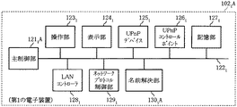
図3は、第1の電子装置の回路構成の要部を表わしたものである。第1の電子装置1021は、装置全体を制御する主制御部1211を備えている。主制御部1211は、図示しないがCPU(Central Processing Unit)とこれが実行する制御プログラムを格納したROM(Read Only Memory)等の制御プログラム格納部を備えている。
FIG. 3 illustrates a main part of the circuit configuration of the first electronic device. The first
主制御部1211は、バス等の通信手段1222を通じて装置内の各部と接続されている。このうち操作部1231はキーボード等の入力装置であり、表示部1241は文字や画像を表示する出力装置である。UPnP(Universal Plug and Play)デバイス1251は、イーサネット(登録商標)や無線LAN等の各種の通信ネットワークに家電製品等の電子装置を接続するだけでこれらの間の通信を可能にする通信デバイスである。
The
UPnPコントロールポイント1261は、UPnPを実装した電子装置を検知し制御する部分である。記憶部1271は、前記したCPUが制御プログラムを実行する際に一時的に必要となるデータを格納する作業用メモリとしての役割を持っている。LANコントローラ1281は、図1に示した家庭内LAN101に対する制御部であり、ネットワークプロトコル制御部1291は通信プロトコルを制御する部分である。名前解決部1301は、他の電子装置から到来したUPnPディスクリプションデータの解析を行って情報源の関連付けを行う。名前解決部1301の内部にはM−SEARCH検出部1311が備えられている。M−SEARCH検出部1311は、UPnPデバイス1251が通信相手からM−SEARCHパケットを受信した際に、これを検出する機能を持っている。
The
なお、主制御部1211に接続されているこれらの各種部品の少なくとも一部は、前記したCPUが制御プログラムを実行することによってソフトウェア的に実現することができる。
Note that at least a part of these various components connected to the
図4は、第2の電子装置の回路構成の要部を表わしたものである。第2の電子装置1022は、電話機としての機能を実現する機器独自構成部1412を除けば、図3に示した第1の電子装置1021と基本的に同一の回路構成となっている。そこで、これらの回路部分については、図3に示した回路部分に付した符号と同一の符号を付しており、これらの説明を省略する。ただし、これらの回路部分を表わす符号は、図3で添え字「1」を記した部分を添え字「2」に変更している。
FIG. 4 shows a main part of the circuit configuration of the second electronic device. The second
このような構成の通信システム100で、一例として第1の電子装置1021が第2の電子装置1022のIPアドレス、MACアドレスおよび装置名といった装置情報を取得する様子を次に説明する。
In the
図5は、電源が投入された後、第2の電子装置が第1の電子装置の装置情報を取得するまでの様子を表わしたものである。図3および図4と共に説明を行う。 FIG. 5 shows a state from when the power is turned on until the second electronic device acquires device information of the first electronic device. This will be described with reference to FIGS.
第1の電子装置1021はその電源が投入された後、名前解決部1301が任意のタイミングでUPnPデバイス1251を起動し(ステップS201)、引き続いてUPnPコントロールポイント1261を起動する(ステップS202)。第2の電子装置1022でもその電源が投入された後、名前解決部1302が任意のタイミングでUPnPデバイス1251を起動し(ステップS301)、引き続いてUPnPコントロールポイント1262を起動する(ステップS302)。
After the first
このようにして第1および第2の電子装置1021、1022の名前解決部1302が起動する際には、それらのディスクリプタ(descriptor)として、マークアップ言語としてのXML(eXtensible Markup Language)データが指定され、それぞれが登録される。
In this way the first and second
図6は第1の電子装置の名前解決部が登録するディスクリプタを示したものであり、図7は第2の電子装置の名前解決部が登録するディスクリプタを示したものである。ディスクリプタは図3に示した記憶部1271あるいは名前解決部1301内の図示しないメモリ領域に登録される。下線4011、4012の箇所が「デバイスタイプ」を表わしており、下線4021、4022の箇所(それぞれ4箇所)が「その他情報」を表わしている。それぞれの内容が異なっており、それぞれが明確に違うデバイスとして動作するように構成されている。
FIG. 6 shows descriptors registered by the name resolution unit of the first electronic device, and FIG. 7 shows descriptors registered by the name resolution unit of the second electronic device. The descriptor is registered in a memory area (not shown) in the
また、第1および第2の電子装置1021、1022のディスクリプタには、自装置の情報が含まれている。下線4031、4032の箇所には、それぞれ自装置のIPアドレス、装置名およびMACアドレスが順に記述されている。
Further, the descriptors of the first and second
図5に戻って説明を続ける。ある時点で第2の電子装置1022の名前解決部1302は、第1の電子装置1021の装置情報を取得する要請が生じ、自装置のUPnPコントロールポイント1262に対して名前解決要求を発行する(ステップS303)。この名前解決要求を受けたUPnPコントロールポイント1262は、図4に示した自装置のネットワークプロトコル制御部1292とLANコントローラ1282を介して、マルチキャストパケットであるM−SEARCHパケットを図1に示した家庭内LAN101に送出する。このM−SEARCHパケットは家庭内LAN101に接続された第2〜第nの電子装置1022〜102nに送出されることになる。しかしながら、ここでは第1および第2の電子装置1021、1022の通信に限定して説明している。したがって、M−SEARCHパケットは相手機端末としての第1の電子装置1021に送出される(ステップS304)。
Returning to FIG. At a certain point in time, the
ここでM−SEARCHパケットは、UPnPネットワークに接続された他の電子装置102を見つけるために発行される検索用のコマンドを内容とするパケットである。このM−SEARCHパケットを受信すると、該当する電子装置102は200 OKを返すようになっている。この例ではM−SEARCHパケットの検索のターゲットには、図6で下線4011で示した「デバイスタイプ」のURN(Uniform Resource Name)が指定される。
Here, the M-SEARCH packet is a packet containing a search command issued to find another
第1の電子装置1021のUPnPデバイス1251は、このM−SEARCHパケットを受信すると、応答(200 OK)を第2の電子装置1022のUPnPコントロールポイント1262に返す(ステップS205)。そこで、第2の電子装置1022のUPnPコントロールポイント1262はこの応答を基にしてUPnPデバイス1251に対して第1の電子装置1021のディスクリプションを要求(GET Description)する(ステップS306)。
Upon receiving this M-SEARCH packet, the
UPnPデバイス1251は、このディスクリプションの要求を受信すると、第1の電子装置1021の登録した自装置のディスクリプタを第2の電子装置1022のUPnPコントロールポイント1262に送信する(ステップS207)。
第2の電子装置1022では、第1の電子装置1021からそのディスクリプタを受け取ると、名前解決部1302がこれを表わしたXMLを解析して(ステップS308)、必要とするデータを抽出して、IPアドレスと装置名の関連付けを行う(ステップS309)。
In the second
図8は、第2の電子装置による第1の電子装置のディスクリプタの解析の原理を表わしたものである。第2の電子装置1022は、図6にも示したディスクリプタにおける下線4031の箇所を、XMLの「<modelDescription>」と「</modelDescription>」の記述に挟まれた領域として抽出し、これをその記述中の縦線で分割する。そして、記憶部1272のそれぞれ対応する領域1531〜1533に格納する。
FIG. 8 shows the principle of analysis of the descriptor of the first electronic device by the second electronic device. The second
この後、第2の電子装置1022の名前解決部1302は表示部1242から情報の取得要求が届くと(ステップS310)には、図8で示した記憶部1272のIPアドレス格納領域1512、装置名格納領域1522およびMACアドレス格納領域1532に格納した第1の電子装置1021に関する情報を返送する(ステップS311)。表示部1242は、受け取った情報が図8に示すようにIPアドレスと装置名およびMACアドレスと対応付けられているので、このうちの装置名を表示する。
Thereafter, when the
この後、第2の電子装置1022が第1の電子装置1021と何らかの通信を行うものとする(ステップS313)。この場合、第2の電子装置1022は名前解決部1302でステップS309によって解決した情報を基にして、装置名をIPアドレスに変換して通信に使用することになる。
Thereafter, it is assumed that the second
図9は、以上説明した第2の電子装置の実際の使用シーンを示したものである。電話機としての第2の電子装置1022から、現時点でIPアドレスの分からないパーソナルコンピュータとしての第1の電子装置1021にファイルの転送を行うものとする。この前提として、第2の電子装置1022は第1の電子装置1021に対してその装置情報(IPアドレス、MACアドレスおよび装置名)の取得を要求する(ステップS321)。第1の電子装置1021はこの要求に対して装置情報を第2の電子装置1022に返送する(ステップS221)。
FIG. 9 shows an actual usage scene of the second electronic device described above. It is assumed that a file is transferred from the second
第2の電子装置1022はこれによって得られた第1の電子装置1021の装置情報の中から「装置名」としての「earth」を抽出してこれを表示部1242(図4参照)に表示する(ステップS323)。利用者は、表示部1242に表示された装置名「earth」を見ることによって、ファイルの送信先を確認することができる。そこで利用者は、この表示された装置名「earth」の第1の電子装置1021に対する通信要求を操作部1232(図4参照)を介して発行する(ステップS324)。
The second
これにより、第2の電子装置1022から第1の電子装置1021に通信が行われることになる。実際の通信に際して、第2の電子装置1022は装置名「earth」を、これに対応付けられたIPアドレス「192.168.0.2」に変換する(ステップS325)。そして、第1の電子装置1021のIPアドレス「192.168.0.2」と、第2の電子装置1022のIPアドレス「192.168.0.3」を用いることで、第2の電子装置1022から第1の電子装置1021へファイル転送が行われることになる(ステップS326)。
As a result, communication is performed from the second
このように以上説明した実施例によれば、家庭内LAN101にUPnPを実装した電子装置1021〜102nを接続することで、表示部1242に装置名を表示しながら実際の通信はIPアドレスを用いて行うので、利用者の使い勝手が向上することになる。
As described above, according to the embodiment described above, by connecting the
図10は、通信ネットワークに接続された電子装置の間で装置情報を交換する様子を表わしたものである。先に説明した図5では、第2の電子装置1022が第1の電子装置1021の装置情報を取得する処理に限定して説明を行った。本実施例では、このような場合に、第1の電子装置1021が第2の電子装置1022の装置情報も同時に取得できるようにして処理の効率化を図っている。この図10で図5と同一のステップ番号については適宜説明を省略する。図3および図4と共に説明を行う。
FIG. 10 shows how device information is exchanged between electronic devices connected to a communication network. In FIG. 5 described above, the description is limited to the process in which the second
ステップS304で第2の電子装置1022のUPnPコントロールポイント1262から第1の電子装置1021のUPnPデバイス1251に対してM−SEARCHパケットが送られてきたとする。第1の電子装置1021のUPnPデバイス1251は、このM−SEARCHパケットを受信すると、応答(200 OK)として第2の電子装置1022のUPnPコントロールポイント1262に返す(ステップS205)ことはすでに説明した。
Assume that an M-SEARCH packet is sent from the
第1の電子装置1021では、その名前解決部1301内のM−SEARCH検出部1311が、自デバイスタイプと同等のM−SEARCHパケットが到来するのを監視している(ステップS241)。ここで自デバイスタイプと同等とは、図6および図7における下線4011、4012で示した「デバイスタイプ」が同等と見なせる範囲をいう。M−SEARCHパケットの送信側では、「デバイスタイプ」という情報をM−SEARCHパケットに付加しておくことで、マルチキャストパケットに対して返答する電子装置を絞り込むことができる。反対に、「デバイスタイプ」という情報で制限しないM−SEARCHパケットをマルチキャストで送信すれば、図1に示した家庭内LAN101に接続された全電子装置1022〜102nが応答(200 OK)の対象となる。
In the first
今説明している例で、第1の電子装置1021は、ステップS304でM−SEARCHパケットが送られてくると、自デバイスタイプと同等であると判別し、これをUPnPデバイス1251内で検出する。この場合、M−SEARCH検出部1311は名前解決部1301を介して自装置のUPnPコントロールポイント1261に名前解決命令を発行する(ステップS242)。
In the example now described, the first
すると、UPnPコントロールポイント1261は、ステップS304の処理と同様に図3に示した自装置のネットワークプロトコル制御部1291とLANコントローラ1281を介して、マルチキャストパケットであるM−SEARCHパケットを相手機端末としての第2の電子装置1022に送出する(ステップS243)。
Then, the
このM−SEARCHパケットを受信した第2の電子装置1022のUPnPデバイス1252は、ステップS205と同様に応答(200 OK)を第1の電子装置1021のUPnPコントロールポイント1261に返す(ステップS341)。第1の電子装置1021のUPnPコントロールポイント1261はこの応答を基にしてUPnPデバイス1252に対して第2の電子装置1022のディスクリプションを要求(GET Description)する(ステップS244)。
The
UPnPデバイス1252は、このディスクリプションの要求を受信すると、第2の電子装置1022のディスクリプタを第1の電子装置1021のUPnPコントロールポイント1261に送信する(ステップS342)。これ以降は、図示を省略するが、図5のステップS308以降で説明したと同様の処理が第1の電子装置1021で行われることになる。
When receiving the description request, the
このように図10に示した処理が行われることにより、一方の電子装置102が他方にその装置情報(IPアドレス、MACアドレスおよび装置名)を要求したとき、他方の装置側も同様の要求を行って、両装置の装置情報が交換できることになる。
By performing the processing shown in FIG. 10 in this way, when one
図11は、通信システムを構成する電子装置に関する情報を最新の情報に保つための処理の流れを示したものである。今まで例として説明した第1および第2の電子装置1021、1022の間で装置情報を最新に保つ場合を例に挙げて説明する。一方の端末としての第2の電子装置1022は、M−SEARCHパケットの送出タイミングおよびディスクリプションの書き換えタイミングの到来を監視している(ステップS501)。
FIG. 11 shows the flow of processing for keeping the information related to the electronic devices constituting the communication system up to date. A case where the device information is kept up-to-date between the first and second
このようなタイミングの到来とは、次のような場合のいずれかが生じたときをいう。
(1)LANリンクアップ(LANケーブルの接続時)
(2)IPアドレスの変更
(3)装置名の変更
(4)IPアドレスの変化の検出
The arrival of such timing means when one of the following cases occurs.
(1) LAN link up (when connecting LAN cable)
(2) IP address change (3) Device name change (4) IP address change detection
このようなタイミングが到来したら(ステップS501:Y)、第2の電子装置1022は、そのUPnPデバイス1252とUPnPコントロールポイント1262を終了させる(ステップS502)。そして、再度、そのUPnPデバイス1252とUPnPコントロールポイント1262を起動して(ステップS503)、M−SEARCHパケットを送出して相手としての第1の電子装置1021の最新の装置情報を取得する処理を開始する(ステップS504)。これは、図5のステップS304以降の処理として説明した。
When such timing comes (step S501: Y), the second
これを基にして第2の電子装置1022側による第1の電子装置1021の装置情報の処理が行われる。この処理の終了前に、図5のステップS304の処理を基にして第1の電子装置1021側が図10のステップS241以降の処理を開始する(ステップS505)。そして、これら第1および第2の電子装置1021、1022による装置情報の取得処理が終了したら(ステップS506:Y)、再びステップS501に戻って装置情報の更新のためのタイミングの到来を監視することになる(リターン)。
Based on this, the device information of the first
このような処理を通信システム100を構成する第1〜第nの電子装置1021〜102nが繰り返すことで、IPアドレス、MACアドレスおよび装置名といった装置情報が常に最新に保たれることになる。
By first to the
以上説明した実施例によれば、特別な名前解決専用機器(DNSサーバ等)を必要とせずに、同様の機能を有する電子装置の間で、装置名やIPアドレス等の情報を交換できる。また、装置情報を交換する対象の電子装置が増えても、特別な設定をせずに自動的に相手と情報交換を行うことができる。更に、電子装置の装置情報は適時自動的に処理され登録されるので、利用者の手動による操作が不要である。 According to the embodiment described above, information such as a device name and an IP address can be exchanged between electronic devices having similar functions without requiring a special name resolution dedicated device (DNS server or the like). Further, even if the number of electronic devices whose device information is to be exchanged increases, information can be automatically exchanged with the other party without any special setting. Furthermore, since the device information of the electronic device is automatically processed and registered in a timely manner, no manual operation by the user is necessary.
なお、以上説明した実施例では、図10のステップS243でM−SEARCHパケットを折り返す形で第2の電子装置1022に送信すると、形式的には第2の電子装置1022がこのM−SEARCHパケットを再度検出して第1の電子装置1021にM−SEARCHパケットを折り返すという現象が発生するおそれがある。しかしながら、これはたとえば次に説明するような手法を採ることで簡単に防止することができる。
In the above in the embodiment described, when transmitted to the M-SEARCH packet in a manner folding the second
その第1の手法は、名前解決命令が最初に発行されてから一定時間(例えば数10秒)内に自装置に届いたM−SEARCHパケットは、折り返しによるパケットであるとして、再度の折り返しを行わないという手法である。また、折り返しを行うことのできる電子装置を1対の装置のうちの片方に制限するという第2の手法も有効である。たとえば、「デバイスタイプ」が「myPC」となったUPnPデバイス125は、折り返しを行わず、「myDevice」という「デバイスタイプ」を持つUPnPデバイス125は、折り返しを行うというように規定することになる。
The first technique is that the M-SEARCH packet that reaches the device within a certain period of time (for example, several tens of seconds) after the name resolution instruction is first issued is considered to be a return packet and is returned again. There is no technique. In addition, the second method of restricting the electronic device that can be turned back to one of a pair of devices is also effective. For example, the
<発明の変形例> <Modification of the invention>
図12は、本発明の変形例における第1の電子装置の構成を表わしたものである。図12で図3と同一部分には同一の符号を付しており、これらの説明を適宜省略する。 FIG. 12 shows a configuration of a first electronic device according to a modification of the present invention. In FIG. 12, the same parts as those in FIG. 3 are denoted by the same reference numerals, and description thereof will be omitted as appropriate.
この変形例の第1の電子装置1022Aは、名前解決部1301Aに図3に示したM−SEARCH検出部1311が配置されていない。このため、図10で説明したようにたとえば相手となる第2の電子装置1022のM−SEARCHパケットが到来したときにこれを装置側で検出し(ステップS241)、装置側で名前解決命令を発行する(ステップS242)ような制御プログラムは主制御部1211Aに組み込まれていない。そこで、利用者は第2の電子装置1022の装置情報(IPアドレス、MACアドレス、装置名)の取得を手動で行うことになる。
In the first electronic device 102 2 A of this modification, the M-
<発明のその他の変形可能性> <Other deformation possibilities of the invention>
以上説明した実施例では、図11のステップS501に示すタイミングで相手先の電子装置と装置情報の交換を行うことにしたが、これに限るものではない。たとえば電子装置にハードウェアあるいはソフトウェアによってタイマ回路を設けておき、定期的に特定の電子装置と情報を交換するように構成することもできる。このような構成にすれば、相手先の電子装置の電源がオフになった等の原因により通信ができなくなったことを知ることができる。このため、相手先の電子装置の生存チェックが可能になる。 In the embodiment described above, the device information is exchanged with the counterpart electronic device at the timing shown in step S501 in FIG. 11, but the present invention is not limited to this. For example, a timer circuit may be provided in the electronic device by hardware or software, and information may be periodically exchanged with a specific electronic device. With such a configuration, it is possible to know that communication has become impossible due to the power source of the electronic device at the other end being turned off. For this reason, the existence check of the electronic device of the other party can be performed.
また、実施例では2台の電子装置の間の1対1による通信について説明したが、1対複数あるいは複数対複数の通信に本発明を適用できることは当然である。また、M−SEARCHパケットはマルチキャストパケットであるため、パケットを1つ発行すれば、通信ネットワーク内のUPnP機能を持つ複数の装置にこれを届けることができる。 In the embodiment, the one-to-one communication between the two electronic devices has been described. However, it is natural that the present invention can be applied to one-to-multiple or multiple-to-multiple communication. Also, since the M-SEARCH packet is a multicast packet, if one packet is issued, it can be delivered to a plurality of devices having the UPnP function in the communication network.
このため各端末は図8で示した記憶部1271内のIPアドレス格納領域1512、装置名格納領域1522およびMACアドレス格納領域1532にそれぞれの電子装置102に対応させる形で装置情報を格納するようにすることでこれら複数の電子装置の装置情報を管理することができる。これにより、たとえばIPアドレス格納領域1512における図1に示す第3の電子装置1023に対応する箇所に、「IPエラー!ハイパーリンクの参照に誤りがあります。」といった注意を喚起するデータを保持することも可能になる。
Therefore, each terminal stores device information in a form corresponding to each
また、記憶部1271内に格納する装置情報がそれぞれの電子装置1021〜102nの間で重複しない仕組みが必要である。このためには、たとえばMACアドレス格納領域1532に格納するMACアドレスごとに情報を格納するようにすればよい。これにより、たとえは同一のMACアドレスについての装置情報は同一のメモリ空間に書き込まれることになる。
Further, a mechanism is required in which the device information stored in the
更に実施例では家庭内LANを説明したが、本発明は一般の通信ネットワークに広く適用できることは当然である。 Further, although the home LAN has been described in the embodiments, it is natural that the present invention can be widely applied to general communication networks.
100 通信システム
101 家庭内LAN
102 電子装置
121 主制御部
125 UPnPデバイス
126 UPnPコントロールポイント
127 記憶部
130 名前解決部
131 M−SEARCH検出部
151 IPアドレス格納領域
152 装置名格納領域
153 MACアドレス格納領域
100
DESCRIPTION OF
Claims (7)
この装置情報返信要求検出手段が前記装置情報の返信の要求を検出したとき要求を行った前記所定の相手側装置の相手側UPnPデバイスにその装置の名前とアドレスを含む装置情報の返信を要求する装置情報折り返し要求手段と、
この装置情報折り返し要求手段の返信の要求に対して前記所定の相手側装置から前記装置情報の返信があったとき、その装置の内容を示すディスクリプションを要求する自装置側UPnPコントロールポイントからなるディスクリプション折り返し要求手段と、
このディスクリプション折り返し要求手段の要求を受信した前記所定の相手側装置の前記相手側UPnPデバイスからその装置のディスクリプタが送られてきたとき、これを受信する前記自装置側UPnPコントロールポイントからなるディスクリプション折り返し受信手段と、
このディスクリプション折り返し受信手段の受信したディスクリプタの予め定めた領域に記載された名前とアドレスを含む装置情報を抽出して前記所定の相手側装置の装置名とアドレスを対応付けることで名前解決を行う折り返し名前解決手段と、
前記所定の相手側装置が前記装置情報の返信を再度要求してきたとき、これを制限する折り返し制限手段
とを具備することを特徴とする電子装置。 When a return of device information of the own device is requested from a partner UPnP control point of a predetermined partner device connected to a communication network that performs TCP / IP (Transmission Control Protocol / Internet Protocol) network communication, this is detected. A device information return request detection means comprising a UPnP device on its own device side;
When this device information reply request detecting means detects a reply request for the device information, it requests a reply of device information including the name and address of the device to the counterpart UPnP device of the predetermined counterpart device that made the request. Device information return request means;
When the device information is returned from the predetermined counterpart device in response to the reply request from the device information return request means, a disk comprising the UPnP control point of the own device that requests a description indicating the contents of the device A caption return request means;
When the descriptor of the device is sent from the counterpart UPnP device of the predetermined counterpart device that has received the request of the description loopback request means, the description comprising the UPnP control point of the own device that receives this descriptor A loopback receiving means;
The device performs name resolution by extracting device information including the name and address described in a predetermined area of the descriptor received by the description return reception unit and associating the device name and address of the predetermined counterpart device. Name resolution means;
An electronic device, comprising: a return limiting means for limiting a response when the predetermined counterpart device requests a return of the device information again .
この装置情報返信要求検出ステップで前記装置情報の返信の要求を検出したとき要求を行った前記所定の相手側装置の相手側UPnPデバイスにその装置の名前とアドレスを含む装置情報の返信を要求する装置情報折り返し要求ステップと、
この装置情報折り返し要求ステップによる返信の要求に対して前記所定の相手側装置から前記装置情報の返信があったとき、その装置の内容を示すディスクリプションを自装置側UPnPコントロールポイントを使用して要求するディスクリプション折り返し要求ステップと、
このディスクリプション折り返し要求ステップによる要求を受信した前記所定の相手側装置の前記相手側UPnPデバイスからその装置のディスクリプタが送られてきたとき、前記自装置側UPnPコントロールポイントを使用してこれを受信するディスクリプション折り返し受信ステップと、
このディスクリプション折り返し受信ステップにより受信したディスクリプタの予め定めた領域に記載された名前とアドレスを含む装置情報を抽出して前記所定の相手側装置の装置名とアドレスを対応付けることで名前解決を行う折り返し名前解決ステップと、
前記所定の相手側装置が前記装置情報の返信を再度要求してきたとき、これを制限する折り返し制限ステップ
とを具備することを特徴とする名前解決方法。 When a return of device information of the own device is requested from a partner UPnP control point of a predetermined partner device connected to a communication network that performs TCP / IP (Transmission Control Protocol / Internet Protocol) network communication, A device information return request detection step for detecting this using a UPnP device;
When the device information reply request detection step detects the device information reply request, the device information reply including the device name and address is requested to the partner UPnP device of the predetermined partner device that made the request. A device information return request step;
When the device information is returned from the predetermined counterpart device in response to the reply request in the device information return request step, a description indicating the contents of the device is requested using the UPnP control point on the own device side. Description wrapping request step to perform,
When a descriptor of the device is sent from the counterpart UPnP device of the predetermined counterpart device that has received the request in the description return request step, the device descriptor is received using the UPnP control point on the own device side. A description return reception step;
A device for performing name resolution by extracting device information including a name and an address described in a predetermined area of the descriptor received by the description return reception step and associating the device name and address of the predetermined counterpart device. A name resolution step;
A name resolving method, comprising: a return restriction step for restricting when the predetermined counterpart device requests a return of the device information again .
前記通信ネットワークに接続された所定の相手側装置の相手側UPnPコントロールポイントから、自装置の装置情報の返信が要求されたとき、前記自装置側UPnPデバイスを使用してこれを検出する装置情報返信要求検出処理と、When a return of the device information of the own device is requested from the counterpart UPnP control point of the predetermined counterpart device connected to the communication network, a device information return is detected using the UPnP device of the own device. Request detection processing;
この装置情報返信要求検出処理で前記装置情報の返信の要求を検出したとき要求を行った前記所定の相手側装置の相手側UPnPデバイスにその装置の名前とアドレスを含む装置情報の返信を要求する装置情報折り返し要求処理と、When the device information reply request detection process detects the device information reply request, the device information reply including the device name and address is requested to the partner UPnP device of the predetermined partner device that made the request. Device information return request processing;
この装置情報折り返し要求処理による返信の要求に対して前記所定の相手側装置から前記装置情報の返信があったとき、その装置の内容を示すディスクリプションを前記自装置側UPnPコントロールポイントを使用して要求するディスクリプション折り返し要求処理と、When the device information is returned from the predetermined counterpart device in response to the reply request by the device information return request processing, a description indicating the content of the device is transmitted using the UPnP control point on the own device side. The requested description wrap request processing;
このディスクリプション折り返し要求処理による要求を受信した前記所定の相手側装置の前記相手側UPnPデバイスからその装置のディスクリプタが送られてきたとき、前記自装置側UPnPコントロールポイントを使用してこれを受信するディスクリプション折り返し受信処理と、When a descriptor of the device is sent from the counterpart UPnP device of the predetermined counterpart device that has received the request by the description loopback request processing, the descriptor is received using the UPnP control point on the own device side. Description loopback reception processing,
このディスクリプション折り返し受信処理により受信したディスクリプタの予め定めた領域に記載された名前とアドレスを含む装置情報を抽出して前記所定の相手側装置の装置名とアドレスを対応付けることで名前解決を行う折り返し名前解決処理と、The device performs name resolution by extracting device information including the name and address described in a predetermined area of the descriptor received by the description return reception processing and associating the device name and address of the predetermined counterpart device. Name resolution processing,
前記所定の相手側装置が前記装置情報の返信を再度要求してきたとき、これを制限する折り返し制限処理When the predetermined counterpart device requests a return of the device information again, a loopback limiting process for limiting this
とを実行させることを特徴とする名前解決制御プログラム。And executing a name resolution control program.
Priority Applications (1)
| Application Number | Priority Date | Filing Date | Title |
|---|---|---|---|
| JP2007099551A JP4945793B2 (en) | 2007-04-05 | 2007-04-05 | Electronic device, name resolution method, and name resolution control program |
Applications Claiming Priority (1)
| Application Number | Priority Date | Filing Date | Title |
|---|---|---|---|
| JP2007099551A JP4945793B2 (en) | 2007-04-05 | 2007-04-05 | Electronic device, name resolution method, and name resolution control program |
Publications (2)
| Publication Number | Publication Date |
|---|---|
| JP2008258965A JP2008258965A (en) | 2008-10-23 |
| JP4945793B2 true JP4945793B2 (en) | 2012-06-06 |
Family
ID=39982094
Family Applications (1)
| Application Number | Title | Priority Date | Filing Date |
|---|---|---|---|
| JP2007099551A Expired - Fee Related JP4945793B2 (en) | 2007-04-05 | 2007-04-05 | Electronic device, name resolution method, and name resolution control program |
Country Status (1)
| Country | Link |
|---|---|
| JP (1) | JP4945793B2 (en) |
Families Citing this family (1)
| Publication number | Priority date | Publication date | Assignee | Title |
|---|---|---|---|---|
| KR101579603B1 (en) * | 2012-06-27 | 2016-01-04 | 네이버 주식회사 | System, method and computer readable recording medium for linking a television and a smart phone using an image authentication key |
Family Cites Families (9)
| Publication number | Priority date | Publication date | Assignee | Title |
|---|---|---|---|---|
| JP2005217974A (en) * | 2004-01-30 | 2005-08-11 | Canon Inc | Electronic device and control method thereof |
| JP4642020B2 (en) * | 2004-10-22 | 2011-03-02 | パナソニック株式会社 | Communication device |
| JP4804364B2 (en) * | 2005-01-13 | 2011-11-02 | パナソニック株式会社 | Communication system, terminal device and communication device |
| JP4799005B2 (en) * | 2005-02-10 | 2011-10-19 | 富士通株式会社 | Information processing device |
| JP2006238226A (en) * | 2005-02-25 | 2006-09-07 | Alpha Systems:Kk | Home network system |
| JP2007028246A (en) * | 2005-07-19 | 2007-02-01 | Matsushita Electric Ind Co Ltd | Reserved recording method |
| JP4217701B2 (en) * | 2005-08-01 | 2009-02-04 | キヤノン株式会社 | Information processing apparatus, method, and control program |
| JP4600992B2 (en) * | 2005-08-17 | 2010-12-22 | Kddi株式会社 | Home appliance remote control system and operation method thereof |
| JP2007081497A (en) * | 2005-09-12 | 2007-03-29 | Canon Inc | Wireless communication apparatus and control method thereof |
-
2007
- 2007-04-05 JP JP2007099551A patent/JP4945793B2/en not_active Expired - Fee Related
Also Published As
| Publication number | Publication date |
|---|---|
| JP2008258965A (en) | 2008-10-23 |
Similar Documents
| Publication | Publication Date | Title |
|---|---|---|
| US20090119766A1 (en) | Method for Remotely Accessing a Local Area Network, and Switching Node for Carrying Out the Method | |
| US8954603B2 (en) | Communication device and communication method of the same | |
| CN100518125C (en) | Communication apparatus, system, method | |
| JP5821576B2 (en) | Relay device and method for starting electronic device | |
| JP2007208317A (en) | Domain name system | |
| JP2011128957A (en) | Media information sharing system and media information sharing method | |
| JP2012146197A (en) | Printing support device, printing system and printing support program | |
| US20140365606A1 (en) | Information processing apparatus, information processing method, and program | |
| CN103262502B (en) | The DNS proxy service of multi-core platform | |
| JP4799005B2 (en) | Information processing device | |
| CN101552802A (en) | Information processing method, gateway and network system | |
| JP2006203731A (en) | Network repeating device, network connection information browsing system and network connection information notification method | |
| JP4683345B2 (en) | Network load balancing apparatus, network load balancing method, and program | |
| JP4945793B2 (en) | Electronic device, name resolution method, and name resolution control program | |
| JP3803654B2 (en) | LAN connection device and UPnP device disclosure method | |
| JP2008072519A (en) | Apparatus and method for searching device, and program | |
| US20110235641A1 (en) | Communication apparatus, method of controlling the communication apparatus,and program | |
| JP6002642B2 (en) | Communication node, network system, and device control method | |
| JP2005197936A (en) | Communication system, registering device, and communication device | |
| JP2005327075A (en) | Network configuration establishment method, host apparatus corresponding to network, and target apparatus corresponding to network | |
| JP4721782B2 (en) | Communication management apparatus and communication system | |
| JP2005031725A (en) | Server and repeater | |
| JP4947118B2 (en) | Relay device and relay method | |
| JP5985377B2 (en) | Page synchronous display method and system for displaying private page synchronously among multiple terminals | |
| JP6052039B2 (en) | Information processing apparatus and network connection program |
Legal Events
| Date | Code | Title | Description |
|---|---|---|---|
| A977 | Report on retrieval |
Free format text: JAPANESE INTERMEDIATE CODE: A971007 Effective date: 20090713 |
|
| A131 | Notification of reasons for refusal |
Free format text: JAPANESE INTERMEDIATE CODE: A131 Effective date: 20090721 |
|
| A521 | Written amendment |
Free format text: JAPANESE INTERMEDIATE CODE: A523 Effective date: 20090910 |
|
| A02 | Decision of refusal |
Free format text: JAPANESE INTERMEDIATE CODE: A02 Effective date: 20100223 |
|
| A521 | Written amendment |
Free format text: JAPANESE INTERMEDIATE CODE: A523 Effective date: 20100519 |
|
| A911 | Transfer to examiner for re-examination before appeal (zenchi) |
Free format text: JAPANESE INTERMEDIATE CODE: A911 Effective date: 20100531 |
|
| A912 | Re-examination (zenchi) completed and case transferred to appeal board |
Free format text: JAPANESE INTERMEDIATE CODE: A912 Effective date: 20100618 |
|
| A01 | Written decision to grant a patent or to grant a registration (utility model) |
Free format text: JAPANESE INTERMEDIATE CODE: A01 |
|
| A61 | First payment of annual fees (during grant procedure) |
Free format text: JAPANESE INTERMEDIATE CODE: A61 Effective date: 20120215 |
|
| FPAY | Renewal fee payment (event date is renewal date of database) |
Free format text: PAYMENT UNTIL: 20150316 Year of fee payment: 3 |
|
| R150 | Certificate of patent or registration of utility model |
Free format text: JAPANESE INTERMEDIATE CODE: R150 |
|
| S111 | Request for change of ownership or part of ownership |
Free format text: JAPANESE INTERMEDIATE CODE: R313111 |
|
| R350 | Written notification of registration of transfer |
Free format text: JAPANESE INTERMEDIATE CODE: R350 |
|
| LAPS | Cancellation because of no payment of annual fees |