JP4926801B2 - Sheet processing apparatus and image forming apparatus - Google Patents
Sheet processing apparatus and image forming apparatus Download PDFInfo
- Publication number
- JP4926801B2 JP4926801B2 JP2007108410A JP2007108410A JP4926801B2 JP 4926801 B2 JP4926801 B2 JP 4926801B2 JP 2007108410 A JP2007108410 A JP 2007108410A JP 2007108410 A JP2007108410 A JP 2007108410A JP 4926801 B2 JP4926801 B2 JP 4926801B2
- Authority
- JP
- Japan
- Prior art keywords
- sheet
- processing
- laser
- unit
- waste
- Prior art date
- Legal status (The legal status is an assumption and is not a legal conclusion. Google has not performed a legal analysis and makes no representation as to the accuracy of the status listed.)
- Expired - Fee Related
Links
Images


Classifications
-
- G—PHYSICS
- G03—PHOTOGRAPHY; CINEMATOGRAPHY; ANALOGOUS TECHNIQUES USING WAVES OTHER THAN OPTICAL WAVES; ELECTROGRAPHY; HOLOGRAPHY
- G03G—ELECTROGRAPHY; ELECTROPHOTOGRAPHY; MAGNETOGRAPHY
- G03G15/00—Apparatus for electrographic processes using a charge pattern
- G03G15/65—Apparatus which relate to the handling of copy material
- G03G15/6582—Special processing for irreversibly adding or changing the sheet copy material characteristics or its appearance, e.g. stamping, annotation printing, punching
-
- G—PHYSICS
- G03—PHOTOGRAPHY; CINEMATOGRAPHY; ANALOGOUS TECHNIQUES USING WAVES OTHER THAN OPTICAL WAVES; ELECTROGRAPHY; HOLOGRAPHY
- G03G—ELECTROGRAPHY; ELECTROPHOTOGRAPHY; MAGNETOGRAPHY
- G03G2215/00—Apparatus for electrophotographic processes
- G03G2215/00362—Apparatus for electrophotographic processes relating to the copy medium handling
- G03G2215/00789—Adding properties or qualities to the copy medium
- G03G2215/00814—Cutter
Landscapes
- Physics & Mathematics (AREA)
- General Physics & Mathematics (AREA)
- Laser Beam Processing (AREA)
- Folding Of Thin Sheet-Like Materials, Special Discharging Devices, And Others (AREA)
Description
本発明は、シート処理装置及び画像形成装置に関し、特に画像形成済みのシートに対して、レーザ加工手段を用いて加工を施すものに関する。 The present invention relates to a sheet processing apparatus and an image forming apparatus, and more particularly to an apparatus for processing an image-formed sheet using a laser processing unit.
従来、例えば複写機、プリンタ等の画像形成装置においては、画像形成された後のシートに対する綴じ処理等に要する手間を軽減するため、画像形成された後のシートに対して綴じ処理、穿孔処理等を選択的に施すようにしたシート処理装置を備えたものがある。 2. Description of the Related Art Conventionally, in an image forming apparatus such as a copying machine or a printer, a binding process, a punching process, or the like is performed on a sheet after an image is formed in order to reduce the labor required for a binding process on the sheet after an image is formed. Some of them are equipped with a sheet processing apparatus that selectively applies the above.
そして、このようなシート処理装置としては、近年、画像形成済みのシートに対し、所定パルスのレーザ光を照射することにより、シートを自由な形状に切断するレーザ加工手段を備えたものがある(例えば、特許文献1参照)。 In recent years, such a sheet processing apparatus includes a laser processing unit that cuts a sheet into a free shape by irradiating an image-formed sheet with laser light of a predetermined pulse ( For example, see Patent Document 1).
図16は、このようなレーザ加工手段を備えた従来のシート処理装置の構成を示す図である。図16において、7はレーザ光を発信するレーザ発振装置8とレンズ9とを備えたレーザ加工部である。
FIG. 16 is a diagram showing a configuration of a conventional sheet processing apparatus provided with such laser processing means. In FIG. 16,
このレーザ加工部7は、レーザ発振装置8から発信されるレーザ光をレンズ9により収束してシート面Sに焦点を合わせるようにしている。これにより、レーザ光の進行方向において焦点から前後方向の所定距離内の範囲(以下、加工可能範囲という)ではシートSを切断できる出力が得られるようになっている。そして、加工形状に応じてレーザ光を制御することで、所望の形状の成果物を得ることができる。
The
ここで、このようなレーザ加工部7を備えたシート処理装置において、不図示の画像形成装置本体から画像形成済のシートが排出されると、このシートは装置入り口16から進入し、第1搬送ローラ対12により搬送パス10に沿って搬送される。
Here, in the sheet processing apparatus provided with such a
次に、このシートは、第2搬送ローラ対13、第3搬送ローラ対14により搬送され、このとき、搬送パス10の上方に配置されたレーザ加工部7の下方を通過する。そして、このようにレーザ加工部7の下方を通過する際にレーザによる切断加工(以下、レーザ切断加工という)が行われ、この後、第3搬送ローラ対14によりスタックトレイ15に排出される。
Next, the sheet is conveyed by the second
なお、図16において、11はシート搬送パス10を挟んでレーザ加工部7と対向する位置に設けられた屑箱であり、このような位置に屑箱11を設けることにより、シート搬送に影響することなくレーザ切断加工によって生じた屑Pdを収納できる。
In FIG. 16,
ところで、このような従来のシート処理装置及び画像形成装置において、レーザ加工部7と対向する位置に回収手段としての屑箱11を設けた場合、継続して切断加工が行われると屑Pdの堆積量(収容量)が増していく。
By the way, in such a conventional sheet processing apparatus and image forming apparatus, when the
ここで、このように屑Pdの堆積(回収)量が増すと、図17に示すようにシートの屑Pdの上面がレーザ光による切断加工が可能となるレーザ光の加工可能範囲に近づくようになる。そして、このようにシートの屑Pdがレーザ光の加工可能範囲に近づくと、後続シートの切断加工時に発せられるレーザ光により、シートの屑Pdが過熱されるおそれがある。 Here, when the accumulation (recovery) amount of the waste Pd increases in this way, the upper surface of the waste Pd of the sheet approaches the laser beam processable range where the laser beam can be cut as shown in FIG. Become. When the sheet waste Pd approaches the laser beam processable range in this way, the sheet waste Pd may be overheated by the laser light emitted during the cutting process of the subsequent sheet.
そこで、本発明は、このような現状に鑑みてなされたものであり、回収された屑がレーザ光により過熱されるのを防ぐことのできるシート処理装置及び画像形成装置を提供することを目的とするものである。 Therefore, the present invention has been made in view of such a current situation, and an object thereof is to provide a sheet processing apparatus and an image forming apparatus that can prevent recovered waste from being overheated by laser light. To do.
本発明は、レーザ光を走査する走査手段を備え、上方からシートにレーザ光を走査しながら照射してシートを加工するレーザ加工手段と、前記レーザ加工手段によるレーザ加工位置の下方に設けられ、前記レーザ加工手段によりシートが加工される際に生じて落下するシートの屑を回収する回収手段と、前記回収手段に堆積され、所定の高さに達したシートの屑を検出する検出手段と、を備え、前記検出手段は、前記走査手段によるレーザ光の走査方向に沿ってシートの屑の堆積高さ検出が可能となるようにレーザ光の走査方向に沿って配置される発光部と受光部とから構成された光学式センサであり、前記検出手段の検出位置をレーザ光の進行方向において焦点から上下方向の所定距離内の、レーザ光による加工が可能な加工可能範囲よりも下方としたことを特徴とするものである。 The present invention includes a scanning unit that scans a laser beam, and is provided below the laser processing position by the laser processing unit, a laser processing unit that processes the sheet by irradiating the sheet while scanning the laser beam from above, A recovery means for recovering and dropping the sheet waste that is generated when the sheet is processed by the laser processing means; a detection means for detecting the waste of the sheet that has been deposited on the recovery means and has reached a predetermined height; And the detecting means includes a light emitting portion and a light receiving portion arranged along the laser light scanning direction so as to enable detection of the accumulated height of sheet scraps along the laser light scanning direction by the scanning means. an optical sensor which is composed of a, the detection position in a predetermined distance from the focal point in the traveling direction of the laser beam in the vertical direction, workable range can be processed by the laser beam of the detection means It is characterized in that it has a lower.
本発明のように、レーザ加工の際、回収手段に堆積するシートの屑の堆積高さを検出する検出手段の検出位置をレーザ光の加工可能範囲よりも下方とすることにより、回収手段に収容された屑がレーザ光により過熱されるのを防ぐことができる。 As in the present invention, during laser processing, the detection position of the detection means for detecting the stack height of the sheet debris deposited on the recovery means is set below the laser beam processable range so that it is accommodated in the recovery means. It is possible to prevent the waste that has been removed from being overheated by the laser beam.
以下、本発明を実施するための最良の形態を、図面を参照しながら詳細に説明する。 Hereinafter, the best mode for carrying out the present invention will be described in detail with reference to the drawings.
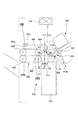
図1は、本発明の第1の実施の形態に係るシート処置装置を備えた画像形成装置の概略構成を示す図である。図1において、50は画像形成装置、50Aは画像形成装置本体、100は画像形成装置本体50Aの上面に設けられた自動原稿給送装置(ADF)、500は画像形成装置本体50Aから排出されたシートの処理を行うシート処理装置であるフィニッシャである。
FIG. 1 is a diagram showing a schematic configuration of an image forming apparatus provided with a sheet treatment apparatus according to a first embodiment of the present invention. In FIG. 1, 50 is an image forming apparatus, 50A is an image forming apparatus main body, 100 is an automatic document feeder (ADF) provided on the upper surface of the image forming apparatus
なお、図1において、200は原稿を画像データに変換するイメージリーダ部(画像入力装置)である。300は複数種類のシートカセット114,115、手差し給紙部125を有し、プリント命令により画像データをシート上に可視像として出力する画像形成部であるプリンタ部である。
In FIG. 1,
そして、このような構成の画像形成装置50において、原稿画像を読取って画像を形成する場合、まず自動原稿給送装置100上に上向きに積載された原稿Dを先頭ページから順に1枚ずつ左方向へ給紙する。この後、湾曲したパスを介してプラテンガラス102上を左から読取り位置を経て右へ搬送し、この後、外部の排紙トレイ112に向けて排出する。
In the
ここで、このように原稿Dがプラテンガラス102上の読取り位置を左から右へ向けて通過するときに、原稿画像は読取り位置に対応する位置に保持されたスキャナユニット104により読取られる。この読取り方法は、一般的に、原稿流し読みと呼ばれる方法である。
Here, when the document D passes through the reading position on the
具体的には、原稿Dが読取り位置を通過する際に、原稿Dの読取り面がスキャナユニット104のランプ103の光で照射され、その原稿からの反射光がミラー105,106,107を介してレンズ108に導かれる。このレンズ108を通過した光は、イメージセンサ109の撮像面に結像する。
Specifically, when the document D passes through the reading position, the reading surface of the document D is irradiated with the light from the
このように読取り位置を左から右へ通過するように原稿Dを搬送することにより、原稿Dの搬送方向に対して直交する方向である幅方向を主走査方向とし、搬送方向を副走査方向とする原稿読取り走査が行われる。即ち、原稿Dが読取り位置を通過する際に主走査方向に原稿画像を1ライン毎にイメージセンサ109で読取りながら、原稿を副走査方向に搬送することによって原稿画像全体の読取りが行われる。
In this way, by transporting the document D so as to pass through the reading position from left to right, the width direction that is orthogonal to the transport direction of the document D is defined as the main scanning direction, and the transport direction is defined as the sub-scanning direction. A document reading scan is performed. That is, when the document D passes through the reading position, the entire document image is read by conveying the document in the sub-scanning direction while reading the document image by the
この後、光学的に読取られた原稿画像はイメージセンサ109によって画像データに変換されて出力される。そして、このようにイメージセンサ109から出力された画像データは、後述する図7に示す画像信号制御部202において、所定の処理が施された後にプリンタ部300の露光制御部110にビデオ信号として入力される。
Thereafter, the optically read original image is converted into image data by the
なお、イメージリーダ部200は、自動原稿給送装置100により原稿をプラテンガラス102上に搬送して所定位置に停止させ、この状態でスキャナユニット104を左から右へ走査させることにより原稿画像を読取ることも可能である。この読取り方法は、いわゆる原稿固定読みと呼ばれる方法である。
Note that the
また、このように自動原稿給送装置100を使用しないで原稿画像を読取るときには、先ず自動原稿給送装置100を持ち上げてプラテンガラス102上に原稿Dを載置する。この後、スキャナユニット104を左から右へ走査させることにより、原稿画像の読取りを行う。即ち、自動原稿給送装置100を使用しないで原稿画像を読取るときには、原稿固定読みが行われる。
When reading an original image without using the
次に、プリンタ部300の露光制御部110は、入力されたビデオ信号に基づきレーザ光を変調して出力する。そして、このレーザ光はポリゴンミラー110aにより走査されながら、予め表面が帯電されている感光ドラム111上に照射され、これにより感光ドラム111上には走査されたレーザ光に応じた静電潜像が形成される。ここで、露光制御部110は、原稿固定読み時には、正しい画像(鏡像でない画像)が形成されるようにレーザ光を出力する。次に、このように感光ドラム111上に形成された静電潜像は、この後、現像器113から供給される現像剤によって現像剤像として可視像化される。
Next, the
一方、レーザ光の照射開始と同期したタイミングで、各カセット114,115、手差給紙部125、又は両面搬送パス124からシートPが給紙され、このシートPは感光ドラム111と転写帯電器116とにより構成される転写部に搬送される。そして、この転写部を通過する際、感光ドラム111に形成された現像剤像は転写帯電器116によりシート上に転写される。
On the other hand, at the timing synchronized with the start of laser light irradiation, the sheet P is fed from each of the
次に、現像剤像が転写されたシートPは定着部117に搬送され、定着部117において加熱及び加圧されることにより、現像剤像がシート上に定着される。そして、このように現像剤像が定着された後、シートPはフラッパ121及び排出ローラ118を経てプリンタ部300から外部(フィニッシャ500)に向けて排出される。
Next, the sheet P to which the developer image has been transferred is conveyed to the
ここで、シートPをその画像形成面が下向きになる状態(フェイスダウン)で排出するときには、まず定着部117を通過したシートPをフラッパ121の切換動作により一旦反転パス122内に導く。次に、シート後端がフラッパ121を通過した後、シートPをスイッチバックさせて排出ローラ118によりプリンタ部300から排出する。
Here, when the sheet P is discharged in a state in which the image forming surface faces downward (face down), the sheet P that has passed through the
なお、このような反転排紙は、自動原稿給送装置100を使用して読取った画像を形成するとき又はコンピュータから出力された画像を形成するとき等のように先頭ページから順に画像形成するときに行われる。そして、このような反転排紙によれば、排紙後のシートの順序は正しいページ順になる。
Note that such reverse paper discharge is used when forming an image sequentially from the first page, such as when forming an image read using the
また、手差給紙部125からOHPシート等の硬いシートPが給紙され、このシートPに画像を形成するときには、シートPを反転パス122に導くことなく、画像形成面を上向きにした状態(フェイスアップ)で排出ローラ118により排出する。
In addition, when a hard sheet P such as an OHP sheet is fed from the manual
更に、シートPの両面に画像形成を行う両面記録が設定されている場合には、フラッパ121の切換動作によりシートPを反転パス122に導いた後に両面搬送パス124へ搬送する。そして、両面搬送パス124へ導かれたシートPを、既述したタイミングで転写部に再度搬送する制御が行われる。
Further, when double-sided recording for image formation is set on both sides of the sheet P, the sheet P is guided to the
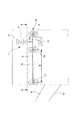
一方、フィニッシャ500は、図2に示すように画像形成装置本体50Aからのシートを取り込み、取り込んだ複数のシートを整合しながら重ね合わせて形成したシート束を針綴じ製本する製本処理部550を備えている。また、シート、あるいはシート束に対し任意の形状の切断処理を行うレーザ切断部400と、切断処理済みの成果物をまとめて積載するスタックトレイ700とを備えている。
On the other hand, the
製本処理部550は、取り込んだ複数のシートを整合しながら重ね合わせるための処理トレイ506と、処理トレイ506上のシート束に対して針綴じを行うステイプルユニット508とを備えている。
The
ここで、処理トレイ506は搬送方向下流側が下方となるように傾斜すると共に、その終端にはストッパ507が設けられている。これにより、処理トレイ506にシートが排出されると、排出されたシートは、重力によりその先端をストッパ507に係止されて収納される。なお、509は処理トレイ上に収納されたシートの幅方向の整合を行う整合板対であり、この整合板対509を整合モータM2により幅方向に移動させることにより、シートの幅方向の整合を行うようにしている。
Here, the
また、ステイプルユニット508は、ストッパ507の上流側近傍に配置されると共に、シートPを挟んで対向配置された、針を突き出すドライバーユニット508aと突き出された針を折り曲げるクリンチャーユニット508bで構成される。
The
なお、図2に示すように製本処理部550の上流部は、プリンタ部300の排出ローラ118から排出されるシートを受け取る入り口ローラ502が設けられている。そして、入口ローラ502で受け取ったシートは、搬送パス503に設けられた搬送ローラ対504,505を経て、処理トレイ506に排出される。
As shown in FIG. 2, an
また、ステイプラユニット508と整合板対509の間には処理トレイ506で作製されたシート束を更に下流に搬送する為の束搬送ローラ対510が設けられている。ここで、この束搬送ローラ対510は、位置が固定された下搬送ローラ510aと、下搬送ローラ510aに対して不図示のソレノイドにより接離自在な上搬送ローラ510bとから構成されている。
A bundle conveying
上搬送ローラ510bは、通常、シートの収容動作を阻害することがないよう処理トレイ506から退避した位置にあり、束排出動作時のみに、下搬送ローラ側に移動し、シート束を搬送するのに充分な挟持搬送力をシートに加えるようになっている。また、この束搬送ローラ対510による束排出動作時には、ストッパ507は不図示のソレノイドにより、処理トレイ上に積載されたシートの上面から後述する図3に示す破線位置まで退避し、下流へのパスを開放するようになっている。
The upper conveying
なお、製本処理部550では、常時ストッパ507を下げ、束搬送ローラ対510をニップさせておけば、処理トレイ506にシートを貯めずにそのまま搬送することも可能である。
In the
また、図2において、511、512は搬送パス503に設けられ、処理トレイ506へ収納されるシートの入り口を切り替えるフラッパであり、これら各フラッパ511,512はシートサイズに応じて適宜切り替えられるようになっている。そして、このようなフラッパ511,512を設けることにより、処理トレイ506にすでに積載されたシートの後端と、次に収納されるシートの先端の衝突を防止することができる。また、M1は搬送モータであり、この搬送モータM1により各ローラ対502,504,505,510は同一の方向に等速で駆動される。
In FIG. 2,
レーザ切断部400は、ストッパ507の下流に配置されると共に、図3及び図4に示すように製本処理部550から送られたシートを受け取る加工搬送ローラ対402を備えている。また、加工搬送ローラ対402が受け取ったシートを機外に排出する加工搬送ベルト対403を備えている。また、綴じ処理等の処理が施されたシート束に対し、所望パルスのレーザ光を照射することにより、シート束を自由な形状に切断するレーザ加工部410を備えている。
The
なお、このレーザ加工手段であるレーザ加工部410は、第2搬送手段である加工搬送ベルト対403と、レーザ加工部410に向けてシートを搬送する第1搬送手段である加工搬送ローラ対402との間に形成されるシート搬送パスの上方に設けられている。
The
ここで、加工搬送ベルト対403は、シート、あるいは成果物を挟持搬送するための上下2対の上加工搬送ベルト403aと、下加工搬送ベルト403bとから構成されるものである。そして、少なくとも下加工搬送ベルト403bは、搬送されるシート、あるいは成果物の幅方向全域を支持できる搬送方向に連続した搬送面を有している。
Here, the processing and conveying
なお、上加工搬送ベルト403aは駆動プーリ404とアイドラプーリ405に掛けられ、下加工搬送ベルト403bは駆動プーリ406とアイドラプーリ407に掛けられている。そして、駆動プーリ404,406を加工搬送モータM3によって回転させて加工搬送ベルト対403を回転させることにより、加工搬送ローラ対402と共にシートを下流(図3の右から左)に搬送するようになっている。
The upper
また、レーザ加工部410は、レーザ発振装置408と、ポリゴンミラー418と、ミラー417と、レンズ416と、エア放出ノズル411とを備えたものである。ここで、レンズ416、ミラー417、ポリゴンミラー418は、レーザ発振装置408から発振されるレーザ光をシート搬送パスに垂直に照射できるように配置されている。
The
また、エア放出ノズル411は、レンズ416からの照射部付近に設けられており、このエア放出ノズル411からはレーザ照射タイミングと同期してエアがシートに向けて放出される。そして、このようにエア放出ノズル411からシートに向けてエアを放出することにより、シートを切断する際に生じる屑を、後述する屑箱に確実に落下させることができる。なお、このエアは不図示のパイプを通してエア供給手段412から供給される。
The
レーザ発振装置408は炭酸ガスレーザを発振するものであり、レンズ416を介してシート搬送パスを通過するシートに焦点が合わされている。その出力は、レーザ光の進行方向において焦点から前後方向の所定範囲である加工可能範囲においてシートを切断するのに適した値に設定されている。
The
そして、このレーザ発振装置408は所定タイミングで、ポリゴンモータM4により一定回転している走査手段であるポリゴンミラー418にパルスレーザを照射するようになっている。これによりシートに対してシート搬送方向と交差する主走査方向のレーザ照射を行うことができる。なお、副走査方向へのレーザ照射は、加工搬送モータM3を駆動してシートを副走査方向であるシート搬送方向下流側へ移動することにより行われる。
The laser
なお、これら加工搬送モータM3及びポリゴンモータM4の駆動は、後述する図7に示すフィニッシャ制御部501により制御されるようになっている。また、レーザ発振装置408のパルスレーザの照射は、後述する切断加工情報(カット情報)が入力されたビデオ信号を基にフィニッシャ制御部501により制御される。このビデオ信号に応じたパルスレーザを照射することにより、シート(束)を所望形状に切断することができる。
The driving of the processing and conveying motor M3 and the polygon motor M4 is controlled by a
ところで、図3に示すように、シート搬送方向におけるシート上の照射位置は、即ちシートの切断(カット)位置は、加工搬送ローラ対402の端からL2、加工搬送ベルト対403の端からL1の位置となっている。また、加工搬送ローラ対402の軸中心と加工搬送ベルト対403の駆動プーリ404の軸中心との間の距離(以下、搬送軸間距離(ニップ間寸法)という)はL3である。さらに、シート上の照射位置と加工搬送ベルト対403の駆動プーリ404の軸中心との間の距離(寸法)はL4である。
Incidentally, as shown in FIG. 3, the irradiation position on the sheet in the sheet conveyance direction, that is, the cutting (cutting) position of the sheet is L2 from the end of the processing
また、加工搬送ローラ対402付近には、シートを案内するガイド対415が設けられており、このガイド対415にはタイミングセンサS1が設けられている。そして、このタイミングセンサS1からの検出信号に基づき、レーザ発振装置408の照射タイミングが決定される。
Further, a
なお、このガイド対415の下方にはレーザにより切断加工されたシートの残り屑を回収する回収手段である屑箱413が取り付けられている。ここで、このガイド対415の上部ガイド415aは、レーザ照射部下流においてシートを加工搬送ベルト対403のニップに導くことができるようにテーパ形状をなしている。また、下部ガイド415bも、加工搬送ベルト対403のニップに導けるようにテーパ形状が設けられている。そして、このようにガイド対415にテーパを形成することにより、加工搬送ローラ対402からのシートを加工搬送ベルト対403間に確実に受け渡しすることができる。
A
なお、加工搬送ローラ対402と加工搬送ベルト対403との間には、不図示のガイド部材が設けられており、このガイド部材により支持されながらシートは、レーザ加工部410の下方を通過するようになっている。なお、このガイド部材にはレーザが走査する全域に渡って、不図示のレーザ加工用の穴が開けられており、この穴の下方に、屑箱413が配設されている。
A guide member (not shown) is provided between the processing and conveying
ここで、この屑箱413の上面にはレーザ走査領域よりも広い回収口が設けられており、これにより加工搬送ローラ対402と加工搬送ベルト対403の間で生じる全ての屑を受け取ることができる。なお、エア放出ノズル411は、屑が屑箱413に確実に落下するようにアシストするものである。
Here, a recovery port wider than the laser scanning region is provided on the upper surface of the
また、屑箱413には、屑の堆積高さを検出する検出手段である検知センサ414が設けられている。ここで、この検知センサ414は、図4に示すように発光部414a,受光部414bを備えた光学式センサである。そして、レーザ光のシート上の照射位置、即ち切断加工位置から下方にレーザ走査方向に平行して発光部414a,受光部414bが回収空間を挟んで取り付けられている。
In addition, the
このように発光部414a,受光部414bを配置することにより、検知センサ414は、レーザ走査方向に沿って位置し、かつ発光部414a,受光部414bの取り付け高さに達した屑を確実に検出できる。
By arranging the
また、この検知センサ414の検出位置は、屑箱413に収容された屑にレーザ発振装置408からのレーザ光が照射されても、屑が過熱されることがないようレーザ光の加工可能範囲から所定距離、下方にずれた位置に設定されている。そして、このように検知センサ414の検出位置を設定することにより、即ち検出位置をレーザ加工が可能なレーザ光の加工可能範囲よりも十分に下方に設定することにより、屑箱413に回収された屑の過熱を防ぐことができる。
In addition, the detection position of the
このように検知センサ414の高さ検出位置を、レーザ光の加工可能範囲から所定距離、下方にずれた位置に設定するのは、レーザ光が屑を切断加工するまでの強度を持たない領域であっても熱を与えることによって煙、匂い等が発生するおそれがあるからである。本実施の形態においてレーザ光は、シート搬送方向と交差する方向に走査されるようになっており、しかも常時点灯するわけではないので、このような構成にすることで安全は確保される。
Thus, the height detection position of the
なお、この検知センサ414が所定時間、屑ありを検出すると、レーザ発振装置408からのパルスレーザ発振は中断され、ユーザに屑箱413の屑捨てを促すアラームを出す。そして、この後、屑の廃棄が行われ、検知センサ414の応答がOFFとなれば、動作は再び継続される。
When this
次に、このように構成されたフィニッシャ500におけるシート(束)切断処理における各部の動作について説明する。
Next, the operation of each part in the sheet (bundle) cutting process in the
ユーザの設定が終了し、スタート信号が送られると、画像形成装置本体50Aによりシートに画像が形成され、この後、画像が形成されたシートは順次、プリンタ部300の排紙ローラ118から排出される。そして、このように排出されたシートは、まずフィニッシャ500の入り口ローラ502で受け取られ、この後、シートサイズに応じた位置に移動しているフラッパ511,512を通過して、処理トレイ506に収容される。
When the user setting is completed and a start signal is sent, an image is formed on the sheet by the image forming apparatus
次に、このように処理トレイ506に収容されたシートは、重力方向の力を受けて先端がストッパ507に当接して位置決めされる。この後、幅方向に広がって待機していた整合板対509がシートを挟みこむことにより、幅方向の整合がなされる。そして、この動作をシート束の最終ページまで繰り返すことにより、図5に示すように所望の枚数のシートPの束PAが処理トレイ506に整合収納され、この後、選択的にステイプルユニット508による針綴じ動作が行われ、シート束PAが綴じられる。
Next, the sheets accommodated in the
次に、離間状態で待機していた束搬送ローラ対510によるシート束PAの挟持が行われると共に、ストッパ507が退避位置へ移動する。この後、束搬送ローラ対510により挟持されたシート束PAは、搬送モータM1と加工搬送モータM3が同期して駆動することで、下流へ搬送される。
Next, the sheet bundle PA is held by the bundle conveying
次に、切断処理が設定されている場合は、シート束PAの先端をタイミングセンサS1で検出することにより、図6に示すようにシート束PAの搬送と同期を取ってレーザ加工部410によるレーザ切断加工が施される。なお、このようなレーザ加工時には、エア放出ノズル411からエアが屑箱413に向けて放出されており、屑Pdが成果物に付着して搬送されたり、ガイド間に飛散したりすることはなく、確実に屑箱413に収容される。
Next, when the cutting process is set, the leading edge of the sheet bundle PA is detected by the timing sensor S1, and the laser by the
このように、2つの搬送手段間でシート束PAに対してレーザ光を照射することにより、シート束PAの任意の個所を切断することが可能であり、この切断処理で生じる屑Pdを確実に屑箱413に収容することができる。
In this way, by irradiating the sheet bundle PA with laser light between the two conveying means, it is possible to cut any part of the sheet bundle PA, and reliably remove the waste Pd generated by this cutting process. It can be accommodated in the
また、レーザ切断加工が実行される毎に、後述する図7に示すフィニッシャ制御部501(CPU回路部150)は、検知センサ414の監視を行う。ここで、検知センサ414の応答がOFFである時、即ち検知センサ414が透過状態のとき、図6のHに示す収納された屑Pdの堆積上面位置は検知センサ414より下方となる。
Further, every time laser cutting is executed, a finisher control unit 501 (CPU circuit unit 150) shown in FIG. 7 described later monitors the
このため、レーザが照射されても、その加工可能範囲は屑Pdの上面から上方にずれている。そして、この状態のときには、レーザが照射された場合でも、レーザは、屑Pdを過熱するエネルギーはなく、レーザ加工の継続が許可される。 For this reason, even if a laser is irradiated, the processable range is shifted upward from the upper surface of the waste Pd. In this state, even when the laser is irradiated, the laser has no energy to overheat the waste Pd, and laser processing is allowed to continue.
一方、検知センサ414がONとなり、このON時間が、屑Pdが落下する所定時間を超えた場合、即ち検知センサ414が遮蔽状態のとき、収納された屑Pdは検知センサ414より上方、即ち加工可能範囲に近いと判断される。
On the other hand, when the
そして、この状態のとき、即ち検知センサ414による屑Pdの検出状態が続いたときには、レーザにより屑Pdが過熱されるおそれがあるため、レーザ切断加工は中断され、ユーザに対して屑Pdの廃棄アラームが出される。なお、このように廃棄アラームが出された後、屑Pdの廃棄が行われると検知センサ414の応答がOFFとなり、これによりレーザ切断加工動作は再び開始される。
In this state, that is, when the detection state of the waste Pd by the
次に、このように切断加工されたシート束PA、即ち成果物は、紙面位置で待機しているスタックトレイ700に、加工搬送ベルト対403により排出される。このとき、成果物は、レーザ加工加工されたレーザ加工位置からスタックトレイ700まで搬送方向で連続した搬送面をもつ加工搬送ベルト対403により搬送されるため、その搬送方向の長さによらず搬送、排出動作が可能となる。
Next, the sheet bundle PA that has been cut and processed, that is, the product, is discharged by the processing and conveying
この動作を所望の束数分繰り返し、ジョブは終了される。なお、加工搬送ベルト対403の代わりに、少なくとも成果物の幅方向の長さよりも長い連続した搬送面を有する複数の搬送ローラを、成果物の搬送方向長さよりも狭いピッチ(間隔)で搬送方向に配するようにしても、この作用は変わらない。
This operation is repeated for the desired number of bundles, and the job is completed. Instead of the processing
図7は、このような構成の画像形成装置全体の制御ブロック図であり、図7に示すように、150は制御手段を構成するCPU回路部である。そして、このCPU回路部150は、不図示のCPU、ROM151、RAM152を内蔵し、ROM151に格納されている制御プログラムにより原稿給送装置制御部101、イメージリーダ制御部201、プリンタ制御部301を制御する。また、このCPU回路部150は画像信号制御部202、切断信号制御部401、フィニッシャ制御部501を制御する。
FIG. 7 is a control block diagram of the entire image forming apparatus having such a configuration. As shown in FIG. 7,
ここで、RAM152は、制御データを一時的に保持し、また、制御に伴う演算処理の作業領域として用いられるものであり、原稿給送装置制御部101は、自動原稿給送装置100をCPU回路部150からの指示に基づき駆動制御するものである。イメージリーダ制御部201は、スキャナユニット104、イメージセンサ109等に対する駆動制御を行い、イメージセンサ109から出力されたアナログ画像信号を、既述したように画像信号制御部202に転送するものである。
Here, the
画像信号制御部202は、イメージセンサ109からのアナログ画像信号をデジタル信号に変換した後に各処理を施し、このデジタル信号をビデオ信号に変換してプリンタ制御部301に出力するものである。また、コンピュータ210から外部I/F209を介して入力されたデジタル画像信号に各種処理を施し、このデジタル画像信号をビデオ信号に変換してプリンタ制御部301に出力するものである。なお、この画像信号制御部202による処理動作は、CPU回路部150により制御される。プリンタ制御部301は、入力されたビデオ信号に基づき既述した露光制御部110を駆動するものである。
The image
なお、図7において、153は画像形成装置本体に設けられた操作部であり、この操作部153は、画像形成に関する各種機能を設定する複数のキー、設定状態を示す情報を表示するための表示部等を有している。そして、各キーの操作に対応するキー信号をCPU回路部150に出力すると共に、CPU回路部150からの信号に基づき対応する情報を表示部に表示する。
In FIG. 7,
切断信号制御部401はコンピュータ210から外部I/F209を介して入力されたデジタル切断信号に各種処理を施し、このデジタル切断信号をビデオ信号に変換してフィニッシャ制御部501に出力する。この切断信号制御部401による処理動作は、CPU回路部150により制御される。
The cutting
フィニッシャ制御部501はフィニッシャ500に搭載され、CPU回路部150と情報のやり取りを行うことによってレーザ加工部を含むフィニッシャ全体の駆動制御を行うものである。
The
本実施の形態において、フィニッシャ制御部501がフィニッシャ500に搭載された構成について説明するが、CPU回路部150と一体的に画像形成装置本体側に設け、画像形成装置本体側から直接制御するようにしてもよい。切断信号制御部401からビデオ信号が入力されると、このビデオ信号に基づき、あるいは操作部153からのシートの搬送方向長さ、シートの先端部分の切断加工長さ及びシートの後端部分の切断加工長さ等の切断加工情報に基づきレーザ加工部410を駆動する。
In this embodiment, a configuration in which the
次に、フィニッシャ制御部501及び切断信号制御部401におけるレーザ加工制御について図8に示すフローチャートを用いて説明する。
Next, laser processing control in the
ユーザの操作によるカット情報は入力手段であるコンピュータ210で設定され、外部インターフェース209を介して切断信号制御部401に送られる。なお、このような切断加工情報(カット情報)としては、先端カット処理を行う場合のカット量、穴明け処理を行う場合の穴あけ量、後端カット処理を行う場合のカット量、及び綴じ処理されたシート束の切断の有無等の情報が含まれる。また、このようなカット情報、即ちシートの先端部分の切断加工長さ及びシートの後端部分の切断加工長さ、あるいはシートの搬送方向長さ等を入力手段である操作部153により入力しても良い。
Cut information by the user's operation is set by the
ここで、切断信号制御部401は、まずカット情報にシート先端に対するカット(切断)処理が含まれているかを判断する(STEP1)。
Here, the cutting
ここで、先端カット処理がある場合は(STEP1のY)、図9に示す切断処理後のシート(以下、最終成果物という)の搬送方向長さlと、既述した図3に示す搬送軸間距離L3とを比較する(STEP2)。 Here, when there is a tip cutting process (Y in STEP 1), the length l in the conveyance direction of the sheet after the cutting process (hereinafter referred to as the final product) shown in FIG. 9 and the conveyance axis shown in FIG. The distance L3 is compared (STEP 2).
ここでl<L3のときは(STEP2のN)、レーザ切断後に、最終成果物を加工搬送ローラ対402から加工搬送ベルト対403に受け渡すことができなくなる。このため、この場合は、ジョブを禁止するよう動作開始前に操作部153の不図示の表示部にアラームを表示する(STEP13)。
If l <L3 (N in STEP 2), the final product cannot be transferred from the processing / conveying
一方、l≧L3のときは(STEP2のY)、次に図9に示す最終成果物から切断する先端部分(以下、先端不要部という)の搬送方向長さl1と、シートへの照射位置と加工搬送ベルト対403の端までの寸法L1(図3参照)とを比較する(STEP3)。ここで、l1≦L1であれば(STEP3のY)、レーザ加工部によって切断された屑は、自重により落下して、屑箱413への収容が可能である。
On the other hand, when l ≧ L3 (Y in STEP 2), the conveyance direction length l1 of the leading end portion (hereinafter referred to as a leading end unnecessary portion) to be cut from the final product shown in FIG. The dimension L1 (see FIG. 3) to the end of the processing and conveying
しかし、l1>L1のときには(STEP3のN)、先端不要部が切断される際、先端不要部の先端が加工搬送ベルト対403に達しているため、そのままでは発生した屑、即ち先端不要部が落下することなく、加工搬送ベルト対403により搬送されてしまう。
However, when l1> L1 (N in STEP 3), when the tip unnecessary portion is cut, the tip of the tip unnecessary portion reaches the processing and conveying
したがって、このときは、即ちシートの先端部分の切断加工位置が、切断加工を開始するときにシートの先端が加工搬送ベルト対403に達する位置と判断した場合には、l1≦L1になるような細分化信号を作成する(STEP14)。これにより、シートの先端が加工搬送ベルト対403に達する前にシートの切断加工位置とシート先端との間の部分を切断加工することができる。
Accordingly, in this case, that is, when it is determined that the cutting position of the leading end portion of the sheet is a position where the leading end of the sheet reaches the processing and conveying
次に、穴あけ処理があるかを判断する(STEP4)。なお、先端切断が無い場合にも(STEP1のN)、次に、穴あけ処理があるかを判断する(STEP4)。ここで、穴あけ処理がある場合(STEP4のY)、図9に示すシートPの穴あけにより切断される中間切断部分Pcの搬送方向長さl2と、シートへの照射位置と加工搬送ベルト対403の端までの寸法L1とを比較する(STEP5)。 Next, it is determined whether there is a drilling process (STEP 4). Even when the tip is not cut (N in STEP 1), it is next determined whether there is a drilling process (STEP 4). Here, when there is a punching process (Y in STEP 4), the conveyance direction length l2 of the intermediate cut portion Pc cut by punching the sheet P shown in FIG. The dimension L1 to the end is compared (STEP 5).
ここで、l2≦L1であれば(STEP5のY)、レーザによって切断された屑は、自重により落下して、屑箱413への収容することができる。しかし、l2>L1のときには(STEP5のN)、穴あけの際、切断部分Pcの先端が加工搬送ベルト対403に達しているため、そのままでは発生した屑、即ち中間切断部分Pcが落下することなく、加工搬送ベルト対403により搬送されてしまう。
Here, if l2 ≦ L1 (Y in STEP 5), the waste cut by the laser can be dropped by its own weight and accommodated in the
したがって、このときは、即ち穴あけ加工位置が、穴あけが終了する前に穴の先端が加工搬送ベルト対403に達する位置と判断した場合には、l2≦L1になるような細分化信号を作成する(STEP15)。つまり、穴あけ処理を行う場合でも、発生した屑を屑箱413に収容するため、l2>L1のときには、l2≦L1になるような細分化信号を作成する。これにより、穴の先端が加工搬送ベルト対403に達する前にシートの穴あけ部分を切断加工することができる。
Therefore, in this case, that is, when it is determined that the drilling position is a position where the tip of the hole reaches the processing and conveying
次に、後端の切断(カット)処理があるかを判断する(STEP6)。なお、穴あけ処理がない場合にも(STEP4のN)、次に、後端の切断(カット)処理があるかを判断する(STEP6)。 Next, it is determined whether or not there is a rear end cutting process (STEP 6). Even when there is no drilling process (N in STEP 4), it is next determined whether or not there is a rear end cutting process (STEP 6).
ここで、後端の切断処理がある場合は(STEP6のY)、最終成果物の搬送方向長さlと、図3に示すシートへの照射位置と加工搬送ベルト対403の駆動プーリ404の軸中心との間の寸法L4とを比較する(STEP7)。ここで、後端の切断処理は、シートPが加工搬送ベルト対403に受け渡された後に行われる為、l≧L4の成果物しか得ることができない。したがって、l<L4のときは(STEP7のN)、ジョブを禁止するよう動作開始前に操作部153の表示部にアラームを表示する(STEP16)。
Here, when there is a cutting process at the rear end (Y in STEP 6), the final product conveyance direction length l, the irradiation position on the sheet shown in FIG. The dimension L4 between the centers is compared (STEP 7). Here, since the cutting process of the rear end is performed after the sheet P is transferred to the processing and conveying
一方、l≧L4のときは(STEP7のY)、次に図9に示す最終成果物から切断する後端部分の搬送方向長さl3と、図3に示す加工搬送ローラ対402の端から加工搬送ベルト対403の端までの寸法L1+L2とを比較する(STEP8)。ここで、l3≦L1+L2であれば(STEP8のY)、レーザによって切断された屑は、自重により落下して、屑箱413への収容が可能である。
On the other hand, when l ≧ L4 (Y in STEP 7), the
しかし、l3>L1+L2のときには(STEP8のN)、最終成果物から切断する後端部分(以下、後端不要部という)は、切断された後、加工搬送ベルト対403に達することができる。このため、そのままでは発生した屑、即ち後端不要部が落下することなく、加工搬送ベルト対403により搬送されてしまう。
However, when l3> L1 + L2 (N of STEP 8), the rear end portion cut from the final product (hereinafter, referred to as a rear end unnecessary portion) can reach the processing
そこで、このように後端部分の切断加工位置が、切断された後端部分の搬送方向長さが加工搬送ローラ対402から加工搬送ベルト対403までの寸法より長くなる位置と判断した場合は、l3≦L1+L2になるような細分化信号を作成する(STEP17)。これにより、切断加工されたシートの後端部分とシート後端との間の部分を加工搬送ローラ対402の端から加工搬送ベルト対403との間隔よりも短くなる位置で切断加工することができる。
Therefore, when it is determined that the cutting position of the rear end portion is a position where the length of the cut rear end portion in the conveyance direction is longer than the dimension from the processing
なお、STEP14、STEP15及びSTEP17で作成された切断信号はフィニッシャ制御部501に送られる。そして、フィニッシャ制御部501は、細分化信号に基づきレーザ加工部410を制御し、先端不要部、中間切断部分Pc及び後端不要部を、図9の破線で示すように分割して切断する。なお、この分割された切断部分の搬送方向長さは、自重により落下して、屑箱413への収容が可能となるようL1よりも短くなっている。
Note that the disconnection signals created in STEP14, STEP15, and STEP17 are sent to the
次に、加工シートは綴じシート束であるかを判断する(STEP9)。なお、後端の切断処理がない場合にも(STEP6のN)、次に、加工シートは綴じシート束であるかを判断する(STEP9)。 Next, it is determined whether the processed sheet is a bound sheet bundle (STEP 9). Even when there is no rear end cutting processing (N in STEP 6), it is next determined whether the processed sheet is a bound sheet bundle (STEP 9).
なお、本実施の形態においては、シート束を綴じる際、図10の(a)に示すように奥側1箇所を針Xで綴じる方法と、図10の(b)に示すように切断加工により、送出予定の全ての成果物P1,P2について綴じ針Xが存在するように綴じる方法がある。 In this embodiment, when binding a sheet bundle, a method of binding one place on the back side with a needle X as shown in FIG. 10A and a cutting process as shown in FIG. 10B. There is a method of binding so that the binding needle X exists for all the deliverables P1 and P2 to be sent.
そこで、加工シートが綴じられたシート束である場合は(STEP9のY)、次に綴じられたシート束PAが、図10の(b)に示すように、全ての成果物P1,P2に綴じ針Xが有るかを判断する(STEP10)。 Therefore, when the processed sheet is a bound sheet bundle (Y in STEP 9), the next bound sheet bundle PA is bound to all the products P1 and P2, as shown in FIG. 10B. It is determined whether or not the needle X is present (STEP 10).
ここで、全ての成果物P1,P2に綴じ針が有る場合には(STEP10のY)、また加工シートが綴じられたシート束でない場合にも(STEP9のN)、切断信号制御部401は、レーザ加工開始信号をフィニッシャ制御部501に出力する。そして、フィニッシャ制御部501は、このレーザ加工開始信号に基づき、レーザ加工を開始する(STEP11)。
Here, when all the products P1 and P2 have binding needles (Y of STEP 10), and when the processed sheets are not bound sheets (N of STEP 9), the cutting
なお、シート束PAが図10の(a)に示すように、全ての成果物P1,P2には綴じ針Xがない場合には(STEP10のN)、シート束PAを走査方向に切断すると、針Xで綴じられていない側の成果物P2は、未綴じ状態で搬送されるようになる。そして、このように未綴じ状態で搬送されると、成果物P2はスタックトレイ700に搬送される前に、分散して搬送不良に陥るおそれがある。したがって、この場合は、ジョブを禁止するよう動作開始前に操作部153の表示部にアラームを表示する(STEP18)。
As shown in FIG. 10A, when all the products P1 and P2 have no binding needle X (N in STEP 10), when the sheet bundle PA is cut in the scanning direction, as shown in FIG. The product P2 on the side not bound by the needle X is conveyed in an unbound state. If the product P2 is conveyed in an unbound state in this manner, the product P2 may be dispersed before the conveyance to the
次に、このような切断信号制御部401からの各種信号に基づき、フィニッシャ制御部501はレーザ加工を開始し、全てのシート束が排出完了すると(STEP12のY)、レーザ切断加工を終了し、次のジョブに備える。
Next, based on the various signals from the cutting
なお、加工された成果物、例えば図10の(b)に示す成果物P1,P2は、加工搬送ベルト対403により、スタックトレイ700に積載される。ここで、スタックトレイ700は、積載されるシートの枚数に関わらず、加工搬送ベルト対403より所定量下降した積載位置となるように、不図示の紙面センサの出力に基づいて正逆転させるトレイモータM5により昇降するようになっている。
The processed products, for example, the products P1 and P2 shown in FIG. 10B are stacked on the
ところで、このようなスタックトレイ700に排出される際、成果物P1,P2は、連続した搬送面をもつ加工搬送ベルト対403によりレーザ加工位置からスタックトレイ700まで搬送されるため、その搬送方向の長さによらず搬送、排出動作は可能である。
By the way, when the products P1 and P2 are discharged to such a
なお、これまでの説明においては、シート束PAを走査方向に複数切断する場合について述べてきたが、図11に示すようにシート束PAを副走査方向に複数切断することもできる。なお、この場合、図11の(b)に示すように全ての成果物P1〜P4に綴じ針が有る場合には、レーザ加工を開始する。 In the above description, the case where a plurality of sheet bundles PA are cut in the scanning direction has been described. However, as shown in FIG. 11, a plurality of sheet bundles PA can be cut in the sub-scanning direction. In this case, when all the products P1 to P4 have binding needles as shown in FIG. 11B, laser processing is started.
一方、図11の(a)に示すように、全ての成果物P1,P2には綴じ針Xがない場合には、シート束PAを副走査方向に切断すると、針Xで綴じられていない側の成果物P2は、未綴じ状態で搬送されるようになる。この場合は、既述したようにジョブを禁止するよう動作開始前に操作部153の表示部にアラームを表示する。
On the other hand, as shown in FIG. 11A, when all the products P1 and P2 do not have the binding needle X, when the sheet bundle PA is cut in the sub-scanning direction, the side not bound by the needle X The deliverable P2 is conveyed in an unbound state. In this case, as described above, an alarm is displayed on the display unit of the
また、シート束PAを副走査方向に切断する場合、図12に示すように成果物P1〜P4の間に不要部Pwがある場合には、先端切断がある場合と同様に、不要部PwをL1以下の長さに細分化信号を作成して、切断処理を実行する。 Further, when the sheet bundle PA is cut in the sub-scanning direction, as shown in FIG. 12, if there is an unnecessary part Pw between the products P1 to P4, the unnecessary part Pw is set in the same manner as in the case where there is a front end cut. A segmentation signal is created to a length equal to or less than L1, and the cutting process is executed.
なお、このように切断加工された成果物P1〜P4は、幅方向に狭くなるが、加工搬送ベルト対403は搬送されるシートの幅方向全域を支持できる面を有しているので、スタックトレイ700までの搬送に支障はない。
Although the products P1 to P4 cut and processed in this manner are narrowed in the width direction, the processing and conveying
このように、シート(束)Pを切断加工する前に、成果物の加工搬送ベルト対403による搬送が可能かを判断し、可能と判断した場合にレーザ加工部410を駆動することにより、成果物を確実に搬送することができる。この結果、搬送パス内での紙詰まりの発生を防ぐことができる。
As described above, before cutting the sheet (bundle) P, it is determined whether the product can be conveyed by the processing
さらに、既述したようにシートの搬送方向長さ、シートの先端部分の切断加工長さ及びシートの後端部分の切断加工長さに応じてレーザ加工部410の駆動を制御することにより、切断されたシートの屑Pdを屑箱413に落下させることができる。これにより、シートが加工される際に生じるシートの屑Pdを、レーザ加工位置の下方に設けられた屑箱413に確実に回収することができる。
Further, as described above, the driving of the
また、本実施の形態のように、屑箱413に堆積された屑Pdの高さを検出する検知センサ414の検出位置をレーザ光による加工が可能な範囲よりも下方とすることにより、屑箱413に回収された屑Pdがレーザ光により過熱されるのを防ぐことができる。
In addition, as in the present embodiment, the detection position of the
ところで、これまで説明したように本実施の形態によれば、シートの屑Pdを屑箱413に確実に回収することができると共に、検知センサ414により屑箱413に堆積された屑Pdが所定の高さとなったことを検出することができる。
As described above, according to the present embodiment, the waste Pd of the sheet can be reliably collected in the
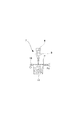
しかし、屑Pdの形状や落下の状況によっては、図13に示すように、検知センサ414は透過状態であるが、実際にはレーザ光の加工可能範囲に近い位置に屑Pdが積載することもある。即ち、検知センサ414が屑Pdの所定の堆積高さを検出しない場合でも、レーザ光の加工可能範囲に近い位置に屑Pdが存在するようになることがある。
However, as shown in FIG. 13, the
そこで、本実施の形態においては、このような場合に備えて、図13に示すように、実際にレーザ光が照射されるレンズ416から検知センサ414の間で、レーザ光線上の屑Pdを検出する領域検出手段としての領域センサ420を設けるようにしている。
Therefore, in this embodiment, in preparation for such a case, as shown in FIG. 13, dust Pd on the laser beam is detected between the
なお、この領域センサ420は、上下方向に複数の不図示の光学式センサが並列された光学式ラインセンサであり、この領域センサ420の不図示の発光部及び受光部は、検知センサ414と同様、回収空間を挟んでレーザ走査方向に平行して取り付けられている。
The
本実施の形態においては、領域センサ420が屑Pdを検出した場合には、フィニッシャ制御部501(CPU回路部150)は、レーザ光の発光を規制、あるいはポリゴンモータM4の回転を制御し、ポリゴンミラー418の回転を規制するようにしている。
In the present embodiment, when the
そして、このようにレーザ光の発光、ポリゴンミラー418の回転を規制することにより、加工をするため搬送されるシートの搬送領域外ではレーザ光の照射を禁止することができる。すなわち、領域センサ420によりシートの屑Pdが検出されたときには、レーザ光の照射領域をシート搬送領域と一致するようポリゴンミラー418の駆動を制御するようにしている。
By thus restricting the emission of the laser beam and the rotation of the
このようにシートの搬送領域外でのレーザ光の照射を禁止することにより、シートに照射されることなく、即ちエネルギーが減少することのない状態のレーザ光がシートの搬送領域外の部分に積載されている屑Pdに直接照射されるのを防ぐことができる。 By prohibiting the irradiation of the laser beam outside the sheet conveyance area in this way, the laser beam that is not irradiated on the sheet, that is, the energy is not reduced, is stacked on the portion outside the sheet conveyance area. It is possible to prevent direct irradiation of the scrap Pd.
なお、レーザ加工時、シートの搬送領域に加工の対象となるシートが存在した場合、たとえシートの搬送領域内でレーザ光の加工可能範囲に屑Pdが存在したとしても、屑Pdに照射されるレーザ光はシートの切断加工後でエネルギーが減少した状態である。 During laser processing, if there is a sheet to be processed in the sheet conveyance area, even if the waste Pd exists in the laser beam processable range within the sheet conveyance area, the waste Pd is irradiated. The laser beam is in a state where energy is reduced after the sheet is cut.
これにより、屑Pdが図13に示すような状態で積載された場合でも、屑Pdがレーザ光により過熱されるのを防ぐことができる。なお、加工の対象となるシートが搬送されていないときにシートの搬送領域内で領域センサ420によって屑Pdを検出した場合はアラームを表示し、注意を喚起するようにしてもよい。
Thereby, even when the waste Pd is loaded in a state as shown in FIG. 13, it is possible to prevent the waste Pd from being overheated by the laser beam. In addition, when the waste sensor Pd is detected by the
次に、本発明の第2の実施の形態について説明する。 Next, a second embodiment of the present invention will be described.
図14は、本実施の形態に係るシート処理装置であるフィニッシャ500の概略構成を示す図である、なお、図14において、既述した図2と同一符号は、同一、又は相当部分を示している。
FIG. 14 is a diagram showing a schematic configuration of a
ここで、本実施の形態においては、レーザ切断部400をプリンタ部300の排紙ローラ118と製本処理部550の間に設けている。
Here, in this embodiment, the
この場合、排紙ローラ118から排出されるシートは加工搬送ローラ対402に受け渡され、レーザ切断部400を通過して、処理トレイ506に収納される。この後、シートは、整合、ステイプル処理が行われた後、束排出ローラ513によりスタックトレイ700に排出される。なお、束排出ローラ513は搬送モータM1で駆動される。
In this case, the sheet discharged from the
ここで、本実施の形態の場合、処理トレイ506の上流でレーザ切断処理が行われるため、1枚1枚任意の形状に切断したシートからなる製本を行うことができる。しかし、所望とされる成果物の搬送方向長さlは、レーザ切断部400より下流の搬送ローラピッチ(軸間距離)以上でなければ搬送ができない。
Here, in the case of the present embodiment, since the laser cutting process is performed upstream of the
例えば、本実施の形態において、第2搬送手段を構成する束搬送ローラ対510と束排出ローラ513とのピッチL5が、最大搬送ピッチとすると、l≧L5の必要がある。したがって、本実施の形態の場合は、図15に示すフローチャートのように、カット情報が送られると、切断信号制御部401は、まず成果物の搬送方向長さlと、束搬送ローラ対510と束排出ローラ513とのピッチL5とを比較する(STEP0)。
For example, in this embodiment, if the pitch L5 between the bundle
ここで、l≧L5ならば(STEP0のY)、次にカット情報にシート先端に対するカット(切断)処理が含まれているかを判断する(STEP1)。また、ここでl<L5のときは(STEP0のN)、ジョブを禁止するよう動作開始前に操作部153の不図示の表示部にアラームを表示する(STEP02)。
Here, if l ≧ L5 (Y in STEP 0), it is next determined whether or not the cutting information includes a cutting (cutting) process for the sheet leading edge (STEP 1). If l <L5 (N in STEP 0), an alarm is displayed on a display unit (not shown) of the
なお、この後、切断信号制御部401は、加工シートが綴じシート束であるかの判断を行わないことを除いて、既述した図8に示すフローチャートと同じSTEP2〜STEP8までの処理を行う。
Thereafter, the cutting
つまり、本実施の形態においても、シートの搬送方向長さ、シートの先端部分の切断加工長さ及びシートの後端部分の切断加工長さに応じて、即ちシートの加工位置に応じてレーザ加工部410の駆動を制御するようにしている。これにより、切断されたシートの屑Pdを屑箱413に落下させることができ、この結果、シートが加工される際に生じるシートの屑Pdを、レーザ加工位置の下方に設けられた屑箱413に確実に回収することができる。
That is, also in the present embodiment, laser processing is performed according to the length of the sheet in the conveyance direction, the cutting length of the leading end portion of the sheet, and the cutting length of the trailing end portion of the sheet, that is, according to the processing position of the sheet. The driving of the
また、本実施の形態においても、屑箱413の所定の堆積高さを検出する検知センサ414の検出位置をレーザ光による切断加工が可能な範囲よりも下方とすることにより、屑箱413に回収された屑Pdがレーザ光により過熱されるのを防ぐことができる。
Also in the present embodiment, the detection position of the
そして、この後、切断信号制御部401からの各種信号基づき、フィニッシャ制御部501はレーザ加工を開始し(STEP11)、全てのシート束が排出完了すると(STEP12のY)、次のジョブに備える。
Then, based on various signals from the cutting
ところで、本実施の形態の場合においても、レーザ切断部400において既述した図12に示すような副走査方向にシートを切断する場合がある。この場合でも、成果物を確実に搬送するためには、レーザ切断部400より下流に位置する搬送ローラ504,505,510,513としては、成果物の搬送方向と直交する方向の全域を支持する連続した搬送面を有するものを用いるようにする。
Incidentally, even in the case of the present embodiment, the sheet may be cut in the sub-scanning direction as shown in FIG. Even in this case, in order to reliably transport the product, the
なお、これまでは針綴じしたシート束PAの切断処理について述べてきたが、針綴じを行わない場合、又は1枚毎の搬送であってもレーザ切断処理の動作は変わらない。また、これまでの説明においては、周知のポリゴンミラーを使用してレーザ光を幅方向に走査する場合について説明したが、レーザ発振装置408自体を、別の駆動手段を設けることにより走査させても勿論よい。
Although the cutting process of the staple-bound sheet bundle PA has been described so far, the operation of the laser cutting process does not change even when the staple binding is not performed or even when the sheet is conveyed one by one. In the description so far, the case where the laser beam is scanned in the width direction using a known polygon mirror has been described. However, the
さらに、これまでの説明において、製本処理部550は、ステイプルユニット508を用いた平綴じ製本処理を行うものを例に挙げたが、製本処理部550としては中綴じ製本処理、糊付け製本処理、テープ製本処理、糸綴じ製本処理を行うものであってもよい。
Furthermore, in the description so far, the
150 CPU回路部
210 コンピュータ
300 プリンタ部
400 レーザ切断部
401 切断信号制御部
402 加工搬送ローラ対
403 加工搬送ベルト対
408 レーザ発振装置
410 レーザ加工部
413 屑箱
414 検知センサ
414a 発光部
414b 受光部
418 ポリゴンミラー
420 領域センサ
501 フィニッシャ制御部
506 処理トレイ
507 ストッパ
509 整合板対
510 束搬送ローラ対
513 束排出ローラ
550 製本処理部
700 スタックトレイ
P シート
Pd 屑
150
Claims (5)
前記レーザ加工手段によるレーザ加工位置の下方に設けられ、前記レーザ加工手段によりシートが加工される際に生じて落下するシートの屑を回収する回収手段と、
前記回収手段に堆積され、所定の高さに達したシートの屑を検出する検出手段と、を備え、
前記検出手段は、前記走査手段によるレーザ光の走査方向に沿ってシートの屑の堆積高さ検出が可能となるようにレーザ光の走査方向に沿って配置される発光部と受光部とから構成された光学式センサであり、前記検出手段の検出位置をレーザ光の進行方向において焦点から上下方向の所定距離内の、レーザ光による加工が可能な加工可能範囲よりも下方としたことを特徴とするシート処理装置。 A laser processing unit that includes a scanning unit that scans the laser beam, and irradiates the sheet while scanning the laser beam from above;
A recovery unit that is provided below a laser processing position by the laser processing unit, and that recovers scraps of the sheet that are generated and dropped when the sheet is processed by the laser processing unit;
Detecting means that is deposited on the collecting means and detects sheet waste reaching a predetermined height;
The detection means is composed of a light emitting part and a light receiving part arranged along the laser beam scanning direction so as to enable detection of the accumulation height of the sheet scraps along the laser light scanning direction by the scanning means. an optical sensor which is a feature in that the detection position from the focal point in the traveling direction of the laser beam in the vertical direction within a predetermined distance of the detection means, and a lower than workable range can be processed by the laser beam Sheet processing apparatus.
前記制御手段は、前記検出手段によりシートの屑が検出された時、前記レーザ加工手段の動作を停止するよう制御することを特徴とする請求項1記載のシート処理装置。 Control means for controlling the operation of the laser processing means,
The sheet processing apparatus according to claim 1, wherein the control unit controls the operation of the laser processing unit to stop when the detection unit detects the waste of the sheet.
前記制御手段は、前記領域検出手段によりシートの屑が検出されたときには、レーザ光の照射領域をシート搬送領域と一致するよう前記走査手段の駆動を制御することを特徴とする請求項1乃至3のいずれか1項に記載のシート処理装置。 An area detecting means for detecting sheet waste existing in an area between the detection position of the detecting means and the laser processing position is provided,
Wherein, when the scrap of the sheet is detected by the area detecting means, according to claim 1, wherein the controller controls the driving of the scanning means so as to match the irradiation area of the laser light and the sheet conveying region The sheet processing apparatus according to any one of the above.
Priority Applications (2)
| Application Number | Priority Date | Filing Date | Title |
|---|---|---|---|
| JP2007108410A JP4926801B2 (en) | 2006-06-07 | 2007-04-17 | Sheet processing apparatus and image forming apparatus |
| US11/759,149 US8013272B2 (en) | 2006-06-07 | 2007-06-06 | Sheet processing apparatus and image forming apparatus |
Applications Claiming Priority (3)
| Application Number | Priority Date | Filing Date | Title |
|---|---|---|---|
| JP2006159134 | 2006-06-07 | ||
| JP2006159134 | 2006-06-07 | ||
| JP2007108410A JP4926801B2 (en) | 2006-06-07 | 2007-04-17 | Sheet processing apparatus and image forming apparatus |
Publications (3)
| Publication Number | Publication Date |
|---|---|
| JP2008013367A JP2008013367A (en) | 2008-01-24 |
| JP2008013367A5 JP2008013367A5 (en) | 2010-06-03 |
| JP4926801B2 true JP4926801B2 (en) | 2012-05-09 |
Family
ID=38822149
Family Applications (1)
| Application Number | Title | Priority Date | Filing Date |
|---|---|---|---|
| JP2007108410A Expired - Fee Related JP4926801B2 (en) | 2006-06-07 | 2007-04-17 | Sheet processing apparatus and image forming apparatus |
Country Status (2)
| Country | Link |
|---|---|
| US (1) | US8013272B2 (en) |
| JP (1) | JP4926801B2 (en) |
Families Citing this family (9)
| Publication number | Priority date | Publication date | Assignee | Title |
|---|---|---|---|---|
| DE102008011493A1 (en) * | 2008-02-20 | 2009-08-27 | Spm Steuer Gmbh & Co. Kg | Method for disposal of spent embossing foil web and embossing device with continuously operating disposal device |
| US20100143015A1 (en) * | 2008-12-09 | 2010-06-10 | Nisca Corporation | Sheet processing apparatus and image formation system provided with the same |
| US20130138391A1 (en) * | 2011-11-30 | 2013-05-30 | Zih Corp. | Platen wrap detection |
| FR2989910B1 (en) * | 2012-04-27 | 2015-04-10 | Voith Patent Gmbh | DEVICE FOR MAKING DEBUGING HOLES IN A SUBSTRATE USING A LASER DEVICE |
| US10026540B2 (en) * | 2014-04-02 | 2018-07-17 | Vishay Dale Electronics, Llc | Magnetic components and methods for making same |
| JP6837815B2 (en) * | 2016-11-25 | 2021-03-03 | 株式会社東芝 | Sheet binding device, sheet post-processing device, and image forming device |
| CN108080638B (en) * | 2018-01-30 | 2023-07-04 | 华中科技大学 | Laser 3D printing forming system and forming method for amorphous alloy foil |
| CN108705373B (en) * | 2018-05-30 | 2023-11-24 | 华域视觉科技(上海)有限公司 | Continuous waste conveying device and control method thereof |
| DE102019128861A1 (en) * | 2019-10-25 | 2021-04-29 | Maximilian Neiß | Component |
Family Cites Families (17)
| Publication number | Priority date | Publication date | Assignee | Title |
|---|---|---|---|---|
| US3882770A (en) * | 1973-08-31 | 1975-05-13 | Edwin Mills & Son Limited | Combined shredder and baler |
| JPH0238497B2 (en) * | 1984-12-06 | 1990-08-30 | Mitsubishi Jukogyo Kk | KOIRUSHOJIDOTEEPUSHITATESOCHI |
| US5253030A (en) * | 1989-07-18 | 1993-10-12 | Mita Industrial Co., Ltd. | Image forming apparatus |
| JP2931467B2 (en) * | 1992-02-06 | 1999-08-09 | 富士通株式会社 | Printing equipment |
| DE4442411B4 (en) * | 1994-11-29 | 2007-05-03 | Heidelberger Druckmaschinen Ag | Method of forming paper in a printing machine |
| US6191382B1 (en) * | 1998-04-02 | 2001-02-20 | Avery Dennison Corporation | Dynamic laser cutting apparatus |
| JP3740280B2 (en) * | 1998-05-20 | 2006-02-01 | キヤノン株式会社 | Sheet processing apparatus and image forming apparatus having the same |
| US6978954B2 (en) * | 2001-08-28 | 2005-12-27 | Fellowes, Inc. | Detector for a shredder |
| US7296791B2 (en) * | 2002-02-14 | 2007-11-20 | Canon Kabushiki Kaisha | Image forming apparatus, sheet containing device, sheet inserting device, book-binding system, and sheet processing apparatus |
| US20030215275A1 (en) * | 2002-03-12 | 2003-11-20 | Masahiro Tamura | Sheet finisher with a punching unit |
| JP2004130754A (en) * | 2002-10-15 | 2004-04-30 | Noritsu Koki Co Ltd | Photographic printing device |
| US20060118529A1 (en) * | 2003-01-21 | 2006-06-08 | Tatsuhiko Aoki | Laser cutting device, laser cutting method, and laser cutting system |
| JP4143446B2 (en) * | 2003-03-07 | 2008-09-03 | キヤノンファインテック株式会社 | Sheet processing apparatus and image forming apparatus provided with the apparatus |
| US6816180B1 (en) * | 2003-05-05 | 2004-11-09 | Eastman Kodak Company | Authenticated images on labels |
| JP2004331328A (en) * | 2003-05-08 | 2004-11-25 | Konica Minolta Business Technologies Inc | Edge cutting device and image formation system |
| US7380779B2 (en) * | 2003-10-16 | 2008-06-03 | Canon Kabushiki Kaisha | Sheet processing system |
| US7246961B2 (en) * | 2005-03-11 | 2007-07-24 | Gilmour Daniel A | Printer system and software for adhesive labels |
-
2007
- 2007-04-17 JP JP2007108410A patent/JP4926801B2/en not_active Expired - Fee Related
- 2007-06-06 US US11/759,149 patent/US8013272B2/en not_active Expired - Fee Related
Also Published As
| Publication number | Publication date |
|---|---|
| US8013272B2 (en) | 2011-09-06 |
| US20070286658A1 (en) | 2007-12-13 |
| JP2008013367A (en) | 2008-01-24 |
Similar Documents
| Publication | Publication Date | Title |
|---|---|---|
| JP4926801B2 (en) | Sheet processing apparatus and image forming apparatus | |
| JP4044420B2 (en) | Paper post-processing device | |
| JP5578958B2 (en) | Sheet processing apparatus and image forming system | |
| JP5925157B2 (en) | Sheet stacking apparatus, sheet processing apparatus, and image forming apparatus | |
| US20060238811A1 (en) | Image forming system and post-processing apparatus | |
| JP3805239B2 (en) | Sheet processing apparatus and image forming apparatus having the same | |
| JP2007062912A (en) | Image forming device, its control method, program and recording medium | |
| JP2010159130A (en) | Image forming device | |
| US20090310999A1 (en) | Sheet post-processing apparatus, image forming system and power saving control method | |
| JP2023134845A (en) | Sheet feeding device, image reading device and image forming device | |
| US20070284801A1 (en) | Sheet processing apparatus and image forming apparatus | |
| US20080075491A1 (en) | Image forming apparatus | |
| JP4976752B2 (en) | Sheet processing apparatus and image forming apparatus | |
| JP2008094570A (en) | Image forming system | |
| JP2007050526A (en) | Image forming system, image forming apparatus, method for controlling image forming system and image forming method | |
| JP2007045580A (en) | Sheet feeder and sheet inserting device | |
| JP2007326677A (en) | Sheet processing device and image forming device | |
| JP2009101439A (en) | Cutting device, sheet processor, and image forming device | |
| JP2007069992A (en) | Sheet insertion device and image forming system | |
| JP2005007539A (en) | Sheet processing device and image forming device | |
| JP2008297098A (en) | Sheet processor and image forming device | |
| JP4072386B2 (en) | Sheet conveying apparatus and image forming system | |
| JP2016016908A (en) | Sheet processing device and image forming apparatus | |
| JP2003192215A (en) | Image forming device | |
| JP2004035228A (en) | Sheet conveyance device and image forming system |
Legal Events
| Date | Code | Title | Description |
|---|---|---|---|
| A521 | Written amendment |
Free format text: JAPANESE INTERMEDIATE CODE: A523 Effective date: 20100415 |
|
| A621 | Written request for application examination |
Free format text: JAPANESE INTERMEDIATE CODE: A621 Effective date: 20100415 |
|
| A977 | Report on retrieval |
Free format text: JAPANESE INTERMEDIATE CODE: A971007 Effective date: 20111005 |
|
| A131 | Notification of reasons for refusal |
Free format text: JAPANESE INTERMEDIATE CODE: A131 Effective date: 20111011 |
|
| A521 | Written amendment |
Free format text: JAPANESE INTERMEDIATE CODE: A523 Effective date: 20111208 |
|
| TRDD | Decision of grant or rejection written | ||
| A01 | Written decision to grant a patent or to grant a registration (utility model) |
Free format text: JAPANESE INTERMEDIATE CODE: A01 Effective date: 20120110 |
|
| A01 | Written decision to grant a patent or to grant a registration (utility model) |
Free format text: JAPANESE INTERMEDIATE CODE: A01 |
|
| A61 | First payment of annual fees (during grant procedure) |
Free format text: JAPANESE INTERMEDIATE CODE: A61 Effective date: 20120208 |
|
| FPAY | Renewal fee payment (event date is renewal date of database) |
Free format text: PAYMENT UNTIL: 20150217 Year of fee payment: 3 |
|
| FPAY | Renewal fee payment (event date is renewal date of database) |
Free format text: PAYMENT UNTIL: 20150217 Year of fee payment: 3 |
|
| LAPS | Cancellation because of no payment of annual fees |