JP4920308B2 - Path setting method, node device, and monitoring control device - Google Patents
Path setting method, node device, and monitoring control device Download PDFInfo
- Publication number
- JP4920308B2 JP4920308B2 JP2006143758A JP2006143758A JP4920308B2 JP 4920308 B2 JP4920308 B2 JP 4920308B2 JP 2006143758 A JP2006143758 A JP 2006143758A JP 2006143758 A JP2006143758 A JP 2006143758A JP 4920308 B2 JP4920308 B2 JP 4920308B2
- Authority
- JP
- Japan
- Prior art keywords
- node
- gmpls
- control
- network configuration
- monitoring control
- Prior art date
- Legal status (The legal status is an assumption and is not a legal conclusion. Google has not performed a legal analysis and makes no representation as to the accuracy of the status listed.)
- Expired - Fee Related
Links
Images


Classifications
-
- H—ELECTRICITY
- H04—ELECTRIC COMMUNICATION TECHNIQUE
- H04L—TRANSMISSION OF DIGITAL INFORMATION, e.g. TELEGRAPHIC COMMUNICATION
- H04L41/00—Arrangements for maintenance, administration or management of data switching networks, e.g. of packet switching networks
- H04L41/08—Configuration management of networks or network elements
-
- H—ELECTRICITY
- H04—ELECTRIC COMMUNICATION TECHNIQUE
- H04J—MULTIPLEX COMMUNICATION
- H04J14/00—Optical multiplex systems
- H04J14/02—Wavelength-division multiplex systems
- H04J14/0227—Operation, administration, maintenance or provisioning [OAMP] of WDM networks, e.g. media access, routing or wavelength allocation
- H04J14/0241—Wavelength allocation for communications one-to-one, e.g. unicasting wavelengths
-
- H—ELECTRICITY
- H04—ELECTRIC COMMUNICATION TECHNIQUE
- H04L—TRANSMISSION OF DIGITAL INFORMATION, e.g. TELEGRAPHIC COMMUNICATION
- H04L45/00—Routing or path finding of packets in data switching networks
- H04L45/50—Routing or path finding of packets in data switching networks using label swapping, e.g. multi-protocol label switch [MPLS]
-
- H—ELECTRICITY
- H04—ELECTRIC COMMUNICATION TECHNIQUE
- H04Q—SELECTING
- H04Q11/00—Selecting arrangements for multiplex systems
- H04Q11/0001—Selecting arrangements for multiplex systems using optical switching
- H04Q11/0062—Network aspects
-
- H—ELECTRICITY
- H04—ELECTRIC COMMUNICATION TECHNIQUE
- H04J—MULTIPLEX COMMUNICATION
- H04J14/00—Optical multiplex systems
- H04J14/02—Wavelength-division multiplex systems
- H04J14/0227—Operation, administration, maintenance or provisioning [OAMP] of WDM networks, e.g. media access, routing or wavelength allocation
-
- H—ELECTRICITY
- H04—ELECTRIC COMMUNICATION TECHNIQUE
- H04J—MULTIPLEX COMMUNICATION
- H04J14/00—Optical multiplex systems
- H04J14/02—Wavelength-division multiplex systems
- H04J14/0278—WDM optical network architectures
- H04J14/0283—WDM ring architectures
-
- H—ELECTRICITY
- H04—ELECTRIC COMMUNICATION TECHNIQUE
- H04J—MULTIPLEX COMMUNICATION
- H04J14/00—Optical multiplex systems
- H04J14/02—Wavelength-division multiplex systems
- H04J14/0287—Protection in WDM systems
- H04J14/0293—Optical channel protection
- H04J14/0294—Dedicated protection at the optical channel (1+1)
-
- H—ELECTRICITY
- H04—ELECTRIC COMMUNICATION TECHNIQUE
- H04J—MULTIPLEX COMMUNICATION
- H04J14/00—Optical multiplex systems
- H04J14/02—Wavelength-division multiplex systems
- H04J14/0287—Protection in WDM systems
- H04J14/0293—Optical channel protection
- H04J14/0295—Shared protection at the optical channel (1:1, n:m)
-
- H—ELECTRICITY
- H04—ELECTRIC COMMUNICATION TECHNIQUE
- H04L—TRANSMISSION OF DIGITAL INFORMATION, e.g. TELEGRAPHIC COMMUNICATION
- H04L41/00—Arrangements for maintenance, administration or management of data switching networks, e.g. of packet switching networks
- H04L41/08—Configuration management of networks or network elements
- H04L41/085—Retrieval of network configuration; Tracking network configuration history
- H04L41/0853—Retrieval of network configuration; Tracking network configuration history by actively collecting configuration information or by backing up configuration information
-
- H—ELECTRICITY
- H04—ELECTRIC COMMUNICATION TECHNIQUE
- H04Q—SELECTING
- H04Q11/00—Selecting arrangements for multiplex systems
- H04Q11/0001—Selecting arrangements for multiplex systems using optical switching
- H04Q11/0062—Network aspects
- H04Q2011/0077—Labelling aspects, e.g. multiprotocol label switching [MPLS], G-MPLS, MPAS
-
- H—ELECTRICITY
- H04—ELECTRIC COMMUNICATION TECHNIQUE
- H04Q—SELECTING
- H04Q11/00—Selecting arrangements for multiplex systems
- H04Q11/0001—Selecting arrangements for multiplex systems using optical switching
- H04Q11/0062—Network aspects
- H04Q2011/0079—Operation or maintenance aspects
- H04Q2011/0081—Fault tolerance; Redundancy; Recovery; Reconfigurability
-
- H—ELECTRICITY
- H04—ELECTRIC COMMUNICATION TECHNIQUE
- H04Q—SELECTING
- H04Q11/00—Selecting arrangements for multiplex systems
- H04Q11/0001—Selecting arrangements for multiplex systems using optical switching
- H04Q11/0062—Network aspects
- H04Q2011/009—Topology aspects
- H04Q2011/0092—Ring
Description
本発明は、各国間や国内をカバーするバックボーン網あるいは都市領域や県内網等で使用される光伝送システムのパス設定方法、ノード装置および監視制御装置に係り、特に、GMPLS(Generalized Multi-Protocol Label Switching)搭載ノードとGMPLS非搭載ノードが混在する状態においても効率的なパス設定が可能なパス設定方法、ノード装置および監視制御装置に関する。 The present invention relates to a path setting method, a node device, and a supervisory control device for an optical transmission system used in a backbone network or an urban area or a prefectural network covering each country or country, and more particularly, a GMPLS (Generalized Multi-Protocol Label). The present invention relates to a path setting method, a node device, and a monitoring control device capable of efficiently setting a path even in a state where a mounted node and a non-GMPLS node are mixed.
近年、伝送装置においてノード間相互制御技術の研究開発が盛んである。ノード間相互制御技術として伝送装置などで構成される通信ネットワークにおいてラベルを用いて通信経路を開通する技術としてGMPLS技術がある。GMLS技術は、非特許文献1(RFC3945)に記載があり、サービスの多様化や伝送容量の増大により、ネットワーク上の装置が、ルータ、時分割多重装置、OXC(Optical Cross-Connect)/PXC(Photonic Cross-Connect)と多様化しているのに対し、効率的なネットワーク管理を実現する手段として期待されている。 In recent years, research and development of inter-node mutual control technology has been active in transmission devices. There is a GMPLS technology as a technology for opening a communication path using a label in a communication network composed of a transmission device or the like as an inter-node mutual control technology. The GMLS technology is described in Non-Patent Document 1 (RFC3945), and due to the diversification of services and the increase in transmission capacity, devices on the network become routers, time division multiplexers, OXC (Optical Cross-Connect) / PXC ( It is expected as a means to realize efficient network management.
GMPLSでは、GMPLS RSVP-TE(ReSerVation Protocol-Traffic Engineering)などのシグナリングプロトコル、OSPF-TE(Traffic Engineering Extensions to OSPF(Open Shortest Path First))などのルーティングプロトコルなどのプロトコルにより、ルータなどのパケット・スイッチや、SONET(Synchronous Optical Network)/SDH(Synchronous Digital Hierarchy)などの時分割多重装置や、OXC/PXCなどの波長スイッチなどにより構成される通信ネットワーク上に、ラベルを用いることによりLSP(Label Switched Path)を開通することが可能となる。なお、GMPLS RSVP-TEは非特許文献2(RFC3437)に、OSPF-TEは非特許文献3(RFC3630)に記載がある。 In GMPLS, GMPLS RSVP-TE (ReSerVation Protocol-Traffic Engineering) and other signaling protocols, OSPF-TE (Traffic Engineering Extensions to OSPF (Open Shortest Path First)) and other routing protocols, etc. LSP (Label Switched Path) by using a label on a communication network composed of time division multiplexing devices such as SONET (Synchronous Optical Network) / SDH (Synchronous Digital Hierarchy), wavelength switches such as OXC / PXC, etc. ) Can be opened. Note that GMPLS RSVP-TE is described in Non-Patent Document 2 (RFC3437) and OSPF-TE is described in Non-Patent Document 3 (RFC3630).
現状の通信ネットワークの一部として、通信ネットワークを集中的に管理する装置としてSNMP(Simple Network Management Protocol)やTL1(Transaction Language 1)などのプロトコルを使用したNMS(Network Management System)などの監視制御装置が存在する。 As part of the current communication network, a monitoring control device such as NMS (Network Management System) using protocols such as SNMP (Simple Network Management Protocol) and TL1 (Transaction Language 1) as a device for centrally managing the communication network Exists.
また、送信元クライアント装置において、O-UNI(Optical-User Network Interface)、OIF-UNI-01.0 R2、GMPLS UNIなどのユーザ・コントロールのプロトコルおよびGMPLSを使用し、SONET/SDHやOXC/PXCなどから構成されるコア網をも含んで宛先のクライアントまでのLSPを一貫して開通する技術が検討されている。なお、OIF-UNI-01.0 R2は非特許文献4に、GMPLS UNIは非特許文献5に記載がある。 In addition, the source client device uses a user control protocol such as O-UNI (Optical-User Network Interface), OIF-UNI-01.0 R2, GMPLS UNI, and GMPLS, and uses SONET / SDH or OXC / PXC. A technique for consistently opening an LSP up to a destination client, including a core network composed of the above, has been studied. Note that OIF-UNI-01.0 R2 is described in Non-Patent Document 4, and GMPLS UNI is described in Non-Patent Document 5.
伝送容量の増大に伴い、伝送装置に収容される主信号の通信速度の高速化や、大容量化が進んでいる為、通信ネットワークにおいて障害発生から回復までの時間を極力短時間とすることが要求されている。 As the transmission capacity increases, the communication speed of the main signal accommodated in the transmission device has been increased and the capacity has been increased, so that the time from failure occurrence to recovery in the communication network can be made as short as possible. It is requested.
非特許文献6に記載されている技術では、GMPLS RSVP-TEを拡張し、LSPの端点のノードで障害を検出するか、Notifyメッセージにより端点ノードに障害情報が通知された場合、予備経路への切替を実施することによりLSP障害復旧を可能としている。使用可能な予備経路への切替技術としては、1+1片方向プロテクション、1+1双方向プロテクション、1:1プロテクション、1:Nプロテクション、Re-routingなどである。 In the technology described in Non-Patent Document 6, when GMPLS RSVP-TE is expanded and a failure is detected at an end node of an LSP or failure information is notified to an end point node by a Notify message, LSP failure recovery is enabled by switching. Usable technologies for switching to a backup route include 1 + 1 unidirectional protection, 1 + 1 bidirectional protection, 1: 1 protection, 1: N protection, and re-routing.
既存の通信ネットワークには、GMPLS機能を搭載していないGMPLS非搭載ノードも存在するため、通信ネットワークを構築する際に、GMPLS非搭載ノードとGMPLS搭載ノードが混在することが起こりえる。 In an existing communication network, there is a GMPLS non-installed node that is not equipped with a GMPLS function. Therefore, when a communication network is constructed, a GMPLS non-installed node and a GMPLS-installed node may coexist.
GMPLS搭載ノードとGMPLS非搭載ノードが混在した通信ネットワークの場合、GMPLS非搭載ノードは、GMPLS搭載ノードからは、その存在を認識することができないため、GMPLSによる制御を行うことができない。このため、迅速且つ効率的なリソース活用のために、GMPLS非搭載ノードをも経由するLSPをGMPLSで制御を行うには、GMPLS非搭載ノードに必要な設定を全て完了していることが必要である。また、リソースを有効に活用するには、GMPLSによる突発的かつ動的な資源の予約や割り当てなどが発生したことを契機としてGMPLS非搭載ノードに対する設定を行うことが必要である。 In the case of a communication network in which a GMPLS mounted node and a GMPLS non-mounted node are mixed, the non-GMPLS mounted node cannot recognize the presence from the GMPLS mounted node, and thus cannot perform control by GMPLS. For this reason, in order to use LMP that also passes through a non-GMPLS node for GMPLS in order to use resources quickly and efficiently, it is necessary to complete all necessary settings for the non-GMPLS node. is there. Further, in order to effectively use resources, it is necessary to make settings for nodes not equipped with GMPLS triggered by the occurrence of sudden and dynamic resource reservation or allocation by GMPLS.
GMPLSでは、その利用形態により突発的かつ動的な資源の予約や割り当てなどが行われる為、GMPLS非搭載ノードに対して事前に必要な設定を全て完了させておくことは、現状技術では困難である。更に、GMPLSによる資源の予約や割り当てなどが発生したことを契機にGMPLS非搭載ノードに対する設定を行うことは、現状技術では困難である。 In GMPLS, sudden and dynamic resource reservation and allocation are performed depending on its usage, so it is difficult to complete all necessary settings in advance for non-GMPLS nodes. is there. Furthermore, it is difficult for current technology to make settings for nodes not equipped with GMPLS when resource reservation or allocation by GMPLS occurs.
非特許文献1記載の技術では、予備経路への切替を実施し、障害復旧を行った場合でも、予備経路上にGMPLS非搭載ノードが存在していた場合、GMPLS非搭載ノードに対する設定が完了していなかった場合、切替後のLSPでも障害状態となる。この結果、障害復旧を行うことができない。
In the technology described in
本発明は、GMPLSで突発的または、動的に資源の予約や割り当てなどが発生した際に、監視制御装置により経路上にGMPLS非搭載ノードの有無を判別し、GMPLS非搭載ノードが存在した場合、GMPLSによる処理を保留し、GMPLS非搭載ノードに対して必要な設定を自動的に算出し、GMPLS非搭載ノードに対する設定を完了させた後、GMPLSによる処理を継続させることにより上記課題を解決する。より具体的には以下の通りである。 In the present invention, when a resource reservation or allocation occurs suddenly or dynamically in GMPLS, the monitoring control device determines whether or not there is a GMPLS non-mounted node on the route, and there is a non-GMPLS mounted node , Suspend processing by GMPLS, automatically calculate necessary settings for non-GMPLS nodes, complete settings for non-GMPLS nodes, and continue processing by GMPLS to solve the above problem . More specifically, it is as follows.
第一に、各ノードに監視制御装置との通信インタフェースを設け、監視制御装置は、この通信インタフェースを経由して各ノードの装置構成情報と網構成情報を取得する。監視制御装置は、取得した装置構成情報を装置構成情報データベースに記録する。この装置構成情報データベースを参照することにより、監視制御装置は、GMPLS非搭載通信装置とGMPLS搭載通信装置により構成される通信ネットワークを制御する。 First, each node is provided with a communication interface with the monitoring control device, and the monitoring control device acquires device configuration information and network configuration information of each node via this communication interface. The monitoring control apparatus records the acquired apparatus configuration information in the apparatus configuration information database. By referring to this device configuration information database, the supervisory control device controls a communication network constituted by a non-GMPLS communication device and a GMPLS communication device.
第二に、GMPLS搭載ノードは、監視制御装置に対するGMPLS制御メッセージ通知機能を搭載する。このGMPLS制御メッセージにより、GMPLS搭載ノードで、動的な資源の予約や割り当てが必要な事態が発生した際に、監視制御装置が、それを検出する。この検出に基づいて、監視制御装置は事前設定の要否を判定する。 Secondly, the GMPLS-equipped node is equipped with a GMPLS control message notification function for the monitoring control device. With this GMPLS control message, when a situation that requires dynamic resource reservation or allocation occurs in the GMPLS node, the supervisory control device detects it. Based on this detection, the monitoring control device determines whether or not pre-setting is necessary.
第三に、監視制御装置は、GMPLS経路計算機能を設け、動的な資源の予約や割り当てが必要な事態を検出したとき、GMPLS搭載ノードで選択される経路を算出する。監視制御装置は、GMPLSで選択される経路上にGMPLS非搭載ノードが存在するかどうか判別し、経路上にGMPLS非搭載ノードが存在した場合、経路上に存在する全てのGMPLS非搭載ノードに対してデータスイッチ設定などの、GMPLSによる処理を行う際に必要な設定を行なう。 Third, the supervisory control device provides a GMPLS route calculation function, and calculates a route selected by the GMPLS node when detecting a situation where dynamic resource reservation or allocation is required. The monitoring and control apparatus determines whether or not a non-GMPLS node is present on the route selected by GMPLS. If there is a non-GMPLS node on the route, all the non-GMPLS nodes that are present on the route Then, settings necessary for processing by GMPLS such as data switch setting are performed.
上述した手段のいずれか一つにより、以下の課題のうち少なくとも一つが解決される。
第一に、GMPLS非搭載ノードに対して事前に必要な全ての設定を完了させることが可能となるため、GMPLSによるLSP開通の際に、GMPLS非搭載ノードにより主信号導通に対する支障を排除できる。
At least one of the following problems is solved by any one of the above-described means.
First, since it becomes possible to complete all necessary settings in advance for a node not equipped with GMPLS, it is possible to eliminate troubles for main signal conduction by the node not equipped with GMPLS when the LSP is opened by GMPLS.
第二に、GMPLS非搭載ノードに対して事前に必要な全ての設定を完了させることが可能となるため、GMPLSによる予備経路への切替の際に、GMPLS非搭載通信機器によるGMPLSによる障害復旧への支障を排することができる。 Second, since it is possible to complete all necessary settings in advance for a node not equipped with GMPLS, when switching to a backup path by GMPLS, a failure recovery by GMPLS by a communication device not equipped with GMPLS Can be eliminated.
第三に、監視制御装置が、装置構成と網構成情報を集中的に管理するため、GMPLS搭載ノード内部のGMPLS処理機能部に対する負荷を低減することができる。 Third, since the monitoring and control apparatus centrally manages the apparatus configuration and the network configuration information, it is possible to reduce the load on the GMPLS processing function unit inside the GMPLS node.
本発明により、GMPLS搭載ノードとGMPLS非搭載ノードが混在した通信網において、双方を連携して動作させることによりGMPLSによりGMPLS非搭載ノードをも含めた効率的なLSP開通処理が可能となる。また、GMPLS非搭載通信機器が存在した場合でも、GMPLSによるGMPLS非搭載ノードをも含めた効率的な障害復旧が可能となる。 According to the present invention, in a communication network in which GMPLS mounted nodes and non-GMPLS mounted nodes are mixed, by operating both in cooperation, efficient LSP establishment processing including GMPLS unmounted nodes can be performed by GMPLS. Further, even when there is a non-GMPLS-equipped communication device, efficient failure recovery including GMPLS non-equipped nodes by GMPLS becomes possible.
本発明の実施形態について、以下に実施例を用いて図面を参照しながら説明する。なお、実質同一部位には同じ参照番号を振り説明は繰り返さない。図1は通信ネットワークのブロック図である。図2はコア網を説明するブロック図である。図3はGMPLS搭載ノードのブロック図である。図4はGMPLS非搭載ノードのブロック図である。図5は監視制御装置のブロック図である。図6は装置構成通知処理を説明する遷移図である。図7は装置構成データベースを説明する図である。図8は網構成通知処理を説明する遷移図である。図9は網構成データベースを説明する図である。図10はGMPLS処理開始通知を説明する遷移図である。図11は監視制御装置のGMPLS非搭載ノードに対する事前設定処理のフロー図である。図12はGMPLS非搭載ノードに対する事前設定処理を説明する遷移図である。 Embodiments of the present invention will be described below with reference to the drawings using examples. Note that the same reference numerals are assigned to substantially the same portions, and the description will not be repeated. FIG. 1 is a block diagram of a communication network. FIG. 2 is a block diagram illustrating the core network. FIG. 3 is a block diagram of a GMPLS node. FIG. 4 is a block diagram of a node not equipped with GMPLS. FIG. 5 is a block diagram of the monitoring control device. FIG. 6 is a transition diagram for explaining the device configuration notification process. FIG. 7 is a diagram for explaining the apparatus configuration database. FIG. 8 is a transition diagram illustrating network configuration notification processing. FIG. 9 is a diagram for explaining the network configuration database. FIG. 10 is a transition diagram for explaining the GMPLS process start notification. FIG. 11 is a flowchart of the pre-setting process for the non-GMPLS node of the monitoring control device. FIG. 12 is a transition diagram for explaining pre-setting processing for a node not equipped with GMPLS.
まず、通信ネットワークについて、図1を用いて説明する。
図1に示す通信ネットワーク710は、ルータ、Layer 2 Switch、Layer 3 Switch、WDM(Wavelength Division Multiplexing)、SONET/SDH、OXC/PXCなどのノード100−1〜100−5によりコア網701を構成し、ノードは、ルータ、Layer 2 Switch、Layer 3 Switch、SONET/SDHなどクライアント装置110−1〜110−4と接続されて、構成されている。クライアント装置110には、ユーザコントロールプロトコル600−1、600−2がプログラムとして搭載されていても良い。ユーザコントロールプロトコルとしては、RSVP-TE、GMPLS−UNI、O-UNIなどのプロトコルを使用可能である。
Also not a, the communication network will be described with reference to FIG.
A
なお、本実施例中のプログラムは、必要に応じてFPGA(Field Programmable Gate Array)、DSP(Digital Signal Processor)、ネットワーク・プロセッサなどのハードウェア処理により実現されても良い。 Note that the program in this embodiment may be realized by hardware processing such as an FPGA (Field Programmable Gate Array), a DSP (Digital Signal Processor), and a network processor as necessary.
次に、コア網を説明する。図2に示すコア網701は、GMPLS搭載ノード230とGMPLS非搭載ノード231および監視制御装置251と、各ノードと監視制御装置間を接続する制御信号線252により構成される。また、GMPLS搭載ノード230には、GMPLS610が搭載されており、GMPLSによるノード間相互制御が可能となっている。
Next, the core network will be described. The core network 701 shown in FIG. 2 includes a GMPLS mounted
図2において、現用系LSP(Label Switched Path)200−1がGMPLS搭載ノード230−1 − GMPLS搭載ノード230−2 − GMPLS搭載ノード230−3の主信号上にGMPLSにより開通されている。現用系LSP200−1上で障害が発生すると、GMPLS搭載ノード230−1 − GMPLS搭載ノード230−4 − GMPLS非搭載ノード231 − GMPLS搭載ノード230−3の主信号上の予備系LSP200−2への切替処理が発生する。なお、予備系LSP200−2は、障害発生前に事前に開通しても良い。本明細書において、GMPLSプロトコルを搭載したノードを“GMPLS搭載ノード”、GMPLSプロトコルを搭載しないノードを“GMPLS非搭載ノード”、両者を区別せずに説明する場合は、“ノード”と呼ぶこととする。なお、図2に示す監視制御装置は、クライアント装置の監視、制御をも実施しても良い。また、制御信号線252は、無線を使用する方式であっても良い。
In FIG. 2, a working LSP (Label Switched Path) 200-1 is opened by GMPLS on the main signals of the GMPLS mounted node 230-1-GMPLS mounted node 230-2-GMPLS mounted node 230-3. When a failure occurs on the active LSP 200-1, the GMPLS mounted node 230-1-the GMPLS mounted node 230-4-the GMPLS non-mounted node 231-the GMPLS mounted node 230-3 to the standby LSP 200-2 on the main signal Switching processing occurs. Note that the standby LSP 200-2 may be opened in advance before a failure occurs. In this specification, a node equipped with the GMPLS protocol is referred to as a “GMPLS-equipped node”, a node not equipped with the GMPLS protocol is referred to as a “GMPLS non-equipped node”, and the two nodes are referred to as “nodes”. To do. Note that the monitoring control device shown in FIG. 2 may also monitor and control the client device. Further, the
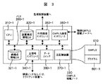
次に、GMPLS搭載ノードのハードウェア構成について、図3を用いて説明する。GMPLS搭載ノード230は、中央演算処理部(CPU)310−1、バスなどの内部通信線390−1、外部通信インタフェース350−1、GMPLS通信インタフェース360−1、装置構成情報データベース320−1、網構成情報データベース321−1、主信号インタフェース340−1、データスイッチ380−1、主記憶装置370−1から構成される。
Next, the hardware configuration of the GMPLS node will be described with reference to FIG. The
主記憶装置370−1は、RAM(Random Access Memory)などの書き換え可能な半導体メモリであり、CPU310−1が実行するプログラム601−1と、GMPLSプロトコル610を記憶している。また、主記憶装置370−1は、装置構成情報データベース320−1または網構成情報データベース321−1を記憶していても良い。
The main storage device 370-1 is a rewritable semiconductor memory such as a RAM (Random Access Memory), and stores a program 601-1 executed by the CPU 310-1 and a
装置構成情報データベース320−1または網構成情報データベース321−1は、ハードディスクなどの二次記憶装置上に記憶されていても良い。また、Flash ROM(Read Only Memory)、Compact Flash、SSFDC(Solid State Floppy(登録商標) Disk Card)、SDメモリカード(Secure Digital memory card)などの書き換え可能な不揮発性半導体メモリなどを用いても良い。 The device configuration information database 320-1 or the network configuration information database 321-1 may be stored on a secondary storage device such as a hard disk. In addition, a rewritable nonvolatile semiconductor memory such as a flash ROM (Read Only Memory), a Compact Flash, an SSFDC (Solid State Floppy (registered trademark) Disk Card), and an SD memory card (Secure Digital memory card) may be used. .
主信号インタフェース340−1は必要に応じて複数も設けても良い。主信号インタフェース340−1は、必要に応じてIEEE 802.3、802.3z、802.3ae等で規定されるEthernet(登録商標)や"International Telecommunication Union Telecommunication Standardization Sector"(ITU-T) G.707やG.783等で規定されるSONET/SDH、ITU-T G.709等で規定されるOTN(Optical TransportNetwork)などの信号方式のものを用いる。主信号インタフェース340−1は、隣接の他のノードと接続され、ユーザデータの交換に用いられる。主信号インタフェース340−1は、更に、クライアント装置と接続され、クライアント装置とのユーザデータの交換にも用いられる。また、データスイッチ380−1は、電気スイッチや、MEMS(Micro Electro Mechanical Systems)方式の光スイッチ、PLC(Planar Lightwave Circuit)方式の光スイッチ、時分割多重スイッチ、ADD/DROPスイッチ等から選択され、主信号の切替および接続を行う。 A plurality of main signal interfaces 340-1 may be provided as necessary. The main signal interface 340-1 may be an Ethernet (registered trademark) or “International Telecommunication Union Telecommunication Standardization Sector” (ITU-T) G.707 or G. A signal system such as SONET / SDH defined by 783 or the like, OTN (Optical Transport Network) defined by ITU-T G.709 or the like is used. The main signal interface 340-1 is connected to other adjacent nodes and used for exchanging user data. The main signal interface 340-1 is further connected to the client device and used for exchanging user data with the client device. The data switch 380-1 is selected from an electrical switch, a MEMS (Micro Electro Mechanical Systems) type optical switch, a PLC (Planar Lightwave Circuit) type optical switch, a time division multiplexing switch, an ADD / DROP switch, and the like. Switch and connect main signal.
GMPLS通信インタフェース360−1は、隣接の他のGMPLS搭載ノードと接続される。GMPLS通信インタフェースを介してルーティングプロトコルやシグナリングプロトコルなどの制御信号と装置構成情報などのデータをやりとりする。GMPLS通信インタフェース360−1は、GMPLSの規定に従って、主信号インタフェースと同一のインタフェースを使用することも可能である。 The GMPLS communication interface 360-1 is connected to another adjacent GMPLS node. Control signals such as routing protocols and signaling protocols and data such as device configuration information are exchanged via the GMPLS communication interface. The GMPLS communication interface 360-1 can use the same interface as the main signal interface in accordance with the GMPLS regulations.
外部通信インタフェース350−1は、監視制御装置251と接続される。外部通信インタフェース350−1は、SNMPやHDLC(High-level Data Link Control procedure)や、TL1などのプロトコルを用いることにより、監視制御装置251との間で網構成情報や、装置構成情報などのデータを交換する。
The external communication interface 350-1 is connected to the
主記憶装置370−1には、GMPLSプロトコル610と、プログラム601−1が格納されており、GMPLSプロトコル610によりGMPLSで規定される処理を、CPU310−1に実現させる。また、プログラム601−1を実行することにより図2に示すコア網で、ノードから監視制御装置へ装置構成情報を通知し(図6を用いて後述する)、また、ノードから監視制御装置へ網構成情報を通知する(図8を用いて後述する)。さらに、図10の処理によりGMPLS搭載ノードからGMPLS制御開始メッセージを監視制御装置に通知する(図10を用いて後述する)ことにより、GMPLS非搭載ノードへの事前設定処理を監視制御装置で実施する(図11を用いて後述する)。主記憶装置上のプログラムは、必要に応じて、上記以外の処理を実施させるものでも良い。
The main storage device 370-1 stores a
次に、GMPLS非搭載ノードのハードウェア構成について、図4を用いて説明する。GMPLS非搭載ノード231は、中央演算処理部(CPU)310−2、バスなどの内部通信線390−2、外部通信インタフェース350−2、装置構成情報データベース320−2、網構成情報データベース321−2、主信号インタフェース340−2、データスイッチ380−2、主記憶装置370−2から構成される。
Next, the hardware configuration of the non-GMPLS node will be described with reference to FIG. The
主記憶装置370−2は、RAMなどの書き換え可能な半導体メモリであり、CPU310−2が実行するプログラム601−2を記憶している。また、主記憶装置370−2は、装置構成情報データベース320−2または網構成情報データベース321−2を記憶していても良い。 The main storage device 370-2 is a rewritable semiconductor memory such as a RAM, and stores a program 601-2 executed by the CPU 310-2. The main storage device 370-2 may store a device configuration information database 320-2 or a network configuration information database 321-2.
装置構成情報データベース320−2または網構成情報データベース321−2は、ハードディスクなどの二次記憶装置上に記憶されていても良い。また、Flash ROMや、Compact Flash、SSFDC、SDメモリカードなどの書き換え可能な不揮発性半導体メモリなどを用いても良い。 The device configuration information database 320-2 or the network configuration information database 321-2 may be stored on a secondary storage device such as a hard disk. In addition, a rewritable nonvolatile semiconductor memory such as a Flash ROM, Compact Flash, SSFDC, and SD memory card may be used.
主信号インタフェース340−2はGMPLS搭載ノードと同様に必要に応じて複数でも良い。主信号インタフェース340−2は、必要に応じてEthernet、SONET/SDH、OTN等の信号方式のものを用いる。主信号インタフェース340−2は、隣接の他のノードと接続され、ユーザデータの交換に用いられる。主信号インタフェース340−2は、更に、クライアント装置と接続され、クライアント装置とのユーザデータの交換にも用いられる。また、データスイッチ380−2は、電気スイッチ、MEMS方式の光スイッチ、PLC方式の光スイッチ、時分割多重スイッチ、ADD/DROPスイッチ等から選択され、主信号の切替および接続を行う。 A plurality of main signal interfaces 340-2 may be provided as necessary, similarly to the GMPLS node. The main signal interface 340-2 uses a signal system such as Ethernet, SONET / SDH, or OTN as necessary. The main signal interface 340-2 is connected to other adjacent nodes and used for exchanging user data. The main signal interface 340-2 is further connected to the client device and used for exchanging user data with the client device. The data switch 380-2 is selected from an electrical switch, a MEMS optical switch, a PLC optical switch, a time division multiplexing switch, an ADD / DROP switch, and the like, and performs switching and connection of the main signal.
外部通信インタフェース350−2は、GMPLS搭載ノード230と同様に監視制御装置251と接続する。外部通信インタフェース350−2は、SNMP、HDLC、TL1などのプロトコルを用いることにより、監視制御装置251と間で網構成情報、装置構成情報などのデータを交換する。
The external communication interface 350-2 is connected to the
主記憶装置370−2には、プログラム601−2を格納する。CPU310−2が、プログラムを実行することにより図2に示すコア網で、ノードから監視制御装置へ装置構成情報を通知し、ノードから監視制御装置へ網構成情報を通知する。そして、監視制御装置251からの指示により、CPU310−2は、パス切替の事前設定処理を実行する。主記憶装置上のプログラムは、必要に応じて、上記以外の処理を実施させるものでも良い。
The main storage device 370-2 stores the program 601-2. The CPU 310-2 executes the program to notify the device configuration information from the node to the monitoring control device and the network configuration information from the node to the monitoring control device in the core network shown in FIG. Then, in response to an instruction from the
次に、監視制御装置のハードウェア構成を図5を用いて説明する。監視制御装置251は、中央演算装置(CPU)310−3、バスなどの内部通信線390−3、外部通信インタフェース350−3、装置構成情報データベース320−3、網構成情報データベース321−3、主記憶装置370−3から構成される。
Next, the hardware configuration of the monitoring control apparatus will be described with reference to FIG. The
外部通信インタフェース350−3は、ノードと接続され、SNMPやHDLC、TL1などのプロトコルを用いることにより、網構成情報や、装置構成情報などのデータを交換する。 The external communication interface 350-3 is connected to a node and exchanges data such as network configuration information and device configuration information by using a protocol such as SNMP, HDLC, or TL1.
主記憶装置370−3は、プログラム601−3を格納しており、CPU310−3がプログラム601−3を実行することで、図2に示すコア網においてコア網内の全てのノードに関する装置構成情報と網構成情報を取得し、装置構成情報データベース320−3、網構成情報データベース321−3を構築する。主記憶装置370−3上のプログラム601−3は、必要に応じて、上記以外の処理をCPU310−3に実施させるものであっても良い。 The main storage device 370-3 stores the program 601-3, and when the CPU 310-3 executes the program 601-3, the device configuration information regarding all nodes in the core network in the core network shown in FIG. The network configuration information is acquired, and the device configuration information database 320-3 and the network configuration information database 321-3 are constructed. The program 601-3 on the main storage device 370-3 may cause the CPU 310-3 to perform processes other than the above as necessary.
装置構成情報データベース320−3および網構成情報データベース321−3は、ハードディスクなどの二次記憶装置上に記憶されている。また、主記憶装置370−3に記憶されても良い。さらに、二次記憶装置として、Flash ROM、Compact Flash、SSFDC、SDメモリカードなどの書き換え可能な不揮発性半導体メモリなどを用いても良い。 The device configuration information database 320-3 and the network configuration information database 321-3 are stored on a secondary storage device such as a hard disk. Further, it may be stored in the main storage device 370-3. Further, a rewritable nonvolatile semiconductor memory such as Flash ROM, Compact Flash, SSFDC, SD memory card, or the like may be used as the secondary storage device.
図6を参照して、ノードと監視制御装置との間の、装置構成通知処理を説明する。ノード100は、オペレータによる作業などにより、主信号インタフェース、データスイッチなどの装置構成に変更が生じた際に、装置構成データベース320−1/2の更新処理を実施する(T601)。更新処理をしたノード100は、制御信号線経由で監視制御装置251へ、装置構成通知メッセージを送信する(T602)。この装置構成通知メッセージには、装置構成の変更内容を記載している。監視制御装置251は、受信した装置構成通知メッセージに基づいて、主記憶装置370−3に格納されているプログラムを実行することにより、装置構成情報データベース320−3の更新処理を実施する(T603)。監視制御装置251は、装置構成情報データベースの更新処理の完了をノードに100対して、装置構成通知確認メッセージを用いて通知する(T604)。装置構成通知確認メッセージを受信したノード100は、監視制御装置内の装置構成情報データベース更新処理により自ノード内の装置構成情報データベースとの同期が完了したことを検知する。なお、装置構成通知確認メッセージは、監視制御装置内での装置構成情報データベース更新結果により、装置構成通知メッセージの再送要求を示す内容であっても良く、監視制御装置内の装置構成情報データベース更新に失敗した場合は、失敗要因を示す内容を含んでいても良い。なお、装置構成通知処理は、自動更新の場合など、繰返し実施されても良く、またオペレータ契機で1回実施しても良い。
With reference to FIG. 6, a device configuration notification process between the node and the monitoring control device will be described. The
さらに、ノード100は、IPアドレス、ノードID、ノード名などのノードを一意に識別可能な値(ノード識別子)と、GMPLS通信インタフェース360、外部通信インタフェース350、主信号インタフェース340、データスイッチ380に関する情報(インタフェース情報)と、インタフェースの種別と、実装位置とを保持する。ノード100がGMPLS搭載ノードの場合は、さらにGMPLS搭載ノードであることを示す情報を保持する。
Further, the
ここで、インタフェースの種別は、GMPLS通信インタフェース360、外部通信インタフェース350、主信号インタフェース340、データスイッチ380のいずれかに関する情報であるかを一意に識別可能な値を使用する。また、インタフェースが主信号インタフェース340の場合、クライアント装置と接続されるインタフェースとノード側に接続されるインタフェースを一意に識別可能な識別子を使用する。 Here, the interface type uses a value that can uniquely identify whether the information is any of the GMPLS communication interface 360, the external communication interface 350, the main signal interface 340, and the data switch 380. Further, when the interface is the main signal interface 340, an identifier that can uniquely identify the interface connected to the client apparatus and the interface connected to the node side is used.
インタフェースの種別が、GMPLS通信インタフェース360もしくは、外部通信インタフェース350の場合は、IPアドレスやサブネットマスクなどの情報をインタフェース情報として保持する。また、インタフェースの種別が主信号インタフェース340の場合は、Ethernet、OTN、SONET/SDHなどのフレームフォーマットに関する情報や、主信号の通信速度情報、主信号の波長情報などをインタフェース情報として保持する。また、種別が、データスイッチ380の場合、データスイッチのスイッチング能力を示す情報や、MEMSや、電気スイッチといったデータスイッチの種類を示す情報などをインタフェース情報として保持する。 When the interface type is GMPLS communication interface 360 or external communication interface 350, information such as an IP address and a subnet mask is held as interface information. When the interface type is the main signal interface 340, information on frame formats such as Ethernet, OTN, SONET / SDH, main signal communication speed information, main signal wavelength information, and the like are held as interface information. When the type is the data switch 380, information indicating the switching capability of the data switch, information indicating the type of the data switch such as a MEMS or an electrical switch, and the like are held as interface information.
また、ノードが保持する実装位置は、それぞれのインタフェースが実装されている位置を一意に識別可能な架番号、ユニット番号、スロット位置情報などの情報である。 The mounting position held by the node is information such as a rack number, a unit number, and slot position information that can uniquely identify the position where each interface is mounted.
ノード100は、これらの情報について装置構成通知メッセージを用いて、制御信号線経由で監視制御装置251へ通知する。これによって、監視制御装置251には、図7に示す装置構成データベースが構築される。図7において、装置構成データベース320−3は、ノード識別子330と、インタフェース情報331と、インタフェース種別332と、実装位置333と、当該ノードがGMPLSノード(Yes)か、否か(−)を示すGMPLS334とにより構成されている。ノード100がGMPLS非搭載ノードの場合は、GMPLS搭載ノードであることを示す情報が、装置構成通知メッセージに含まれないので、GMPLS334は、「−」となっている。
The
図8を参照して、ノードと監視制御装置との間の、網構成通知処理を説明する。オペレータによる作業などにより、網構成に変更が生じた場合、ノード100は、網構成データベース321−1/2の更新処理を実施する(T801)。更新処理をしたノード100は、制御信号線経由で監視制御装置251へ、網構成通知メッセージを送信する(T802)。この網構成通知メッセージには、網構成の変更内容を記載している。監視制御装置251は、受信した網構成通知メッセージに基づいて、主記憶装置370−3に格納されているプログラムを実施することにより、網構成情報データベース321−3の更新処理を実施する(T803)。監視制御装置251は、網構成情報データベースの更新処理の完了をノードに100対して、網構成通知確認メッセージを用いて通知する(T804)。網構成通知確認メッセージを受信したノード100は、監視制御装置内の網構成情報データベース更新処理により自ノード内の網構成情報データベースとの同期が完了したことを検知する。なお、網構成通知確認メッセージは、監視制御装置内での網構成情報データベース更新結果により、網構成通知メッセージの再送要求を示す内容であっても良く、監視制御装置内の網構成情報データベース更新に失敗した場合は、失敗要因を示す内容を含んでいても良い。なお、網構成通知処理は、自動更新の場合など、繰返し実施されても良く、またオペレータ契機で1回実施しても良い。
With reference to FIG. 8, the network configuration notification process between the node and the monitoring control apparatus will be described. When the network configuration is changed due to the operator's work or the like, the
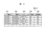
ノード100は、網構成に関する情報をOSPF-TEなどのルーティングプロトコルを使用して収集する。また、網構成に関する情報をオペレータが手動で設定しても良い。この結果、ノード100は、IPアドレス、ノードID、ノード名などのノードを一意に識別可能な値として自ノードのノード識別子と、隣接ノードのノード識別子と、網構成を取得した手段に関する情報としてプロトコル情報とを保持する。また、ノード100がGMPLS搭載ノードの場合、ノード100は、さらに、GMPLSの隣接関係を構築するか否かの情報であるGMPLS隣接を保持する。ここで、GMPLS隣接関係は、GMPLS搭載ノード間でのみ構築する。GMPLS非搭載ノードは、GMPLSを搭載していない為、GMPLS隣接関係を構築することはできない。また、ノード100は、主信号インタフェース同士が接続されていか否かの情報である主信号隣接を保持する。GMPLS隣接および、主信号隣接は、OSPF-TEや、LMP(Link Management Protocol)を使用して収集しても良く、オペレータが手動で設定しても良い。また、OSPF-TEなどの動的ルーティングプロトコルを使用した場合、隣接関係に無いノードに関する情報を収集することも可能である。
The
ノード100は、これらの情報を網構成通知メッセージを用いて、制御信号線経由で監視制御装置251に通知する。これによって、監視制御装置251は、網構成データベース321−3を構築する。
The
図9において、網構成データベース321−3は、ノード識別子1 321と、ノード識別子1 321毎に、そのノード識別子に隣接するノード識別子2 322と、プロトコル323とGMPLS隣接324と、主信号隣接325とから構成されている。ここで、GMPLS隣接324は、ノード識別子1のノードと、ノード識別子2のノードとが共に、GMPLS搭載ノードであり、かつ主信号隣接がYesのときYesとなる。
In FIG. 9, the network configuration database 321-3 includes a
図10を参照して、GMPLS処理開始通知を説明する。GMPLS搭載ノード230は、GMPLSによるLSP開通処理やLSP削除処理、LSP切替処理の発生を監視している。GMPLS搭載ノード230は、これらを契機としたGMPLSによる処理が開始された場合には、GMPLS制御保留処理を実施する(T901)。次に、GMPLS搭載ノード230は、監視制御装置251に対してGMPLS制御開始メッセージを送信する(T902)。この際、GMPLS制御開始メッセージには、LSP切替処理で1+1パスプロテクションなどの切替処理の種別と、予備系の経路情報もあわせて通知を行う。また、LSP開通処理で、中間経路の指定がある場合は、中間経路の情報とを含めても良い。更に、LSP削除処理の場合、GMPLS制御開始通知メッセージには、削除対象LSPを一意に識別可能なPath ID、Path Nameなどの情報を含んでいても良い。
The GMPLS process start notification will be described with reference to FIG. The
なお、一連の処理中にGMPLS制御保留処理により、GMPLS制御がタイム・アウトする可能性があるが、GMPLS制御が保留中で監視制御装置での処理中であるメッセージを、他のGMPLS搭載ノードに対して送信することによりタイム・アウトによる処理失敗を防ぐことが可能である。 Note that there is a possibility that GMPLS control will time out due to GMPLS control hold processing during a series of processing, but a message indicating that GMPLS control is on hold and being processed by the monitoring control device is sent to other GMPLS nodes. In contrast, it is possible to prevent a processing failure due to time-out by transmitting.
監視制御装置251は、GMPLS制御開始メッセージを受信した場合、予備経路上通信機器に対する事前設定処理を実施する(T903)。監視制御装置251は、事前設定が完了すると、GMPLS制御保留解除メッセージをGMPLS搭載ノード230に送信する(T904)。
When the
GMPLS搭載ノード230は、GMPLS制御保留解除メッセージを受信すると、GMPLSによる制御保留を解除して(T905)、GMPLSで規定の処理を実施する。なお、図10の処理は通常繰り返し実施される処理である。
When receiving the GMPLS control hold release message, the GMPLS mounted
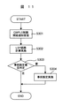
次に、図11を用いて、予備経路上のGMPLS非搭載ノード231に対する事前設定処理の詳細を説明する。ここで、事前設定処理とは、図10のT903の詳細内容である。GMPLS制御開始メッセージを受信したとき(S301)、監視制御装置251は、まず、GMPLS制御開始メッセージに含まれる情報を元に、GMPLS制御後のLSPに関する経路計算処理を実施する(S302)。監視制御装置251は、次にLSP経路上にGMPLS非搭載ノードが存在するかどうかによりGMPLS非搭載ノードに対する事前設定要否の判定処理を実施する(S303)。予備経路計算から得られた情報から、予備系路上に非GMPLS搭載ノードが存在し、事前設定が必要だと判断した場合、GMPLS非搭載ノードに対して、必要なデータスイッチの事前設定を行う(S304)。なお、ステップ303で、予備系路上に非GMPLS搭載ノードが存在しないとき、処理を終了する(図10のT904に遷移する)。
Next, details of the pre-setting process for the
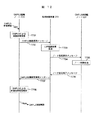
次に、切替経路上にGMPLS非搭載ノードが存在した場合の、GMPLS搭載ノード、監視制御装置、GMPLS非搭載ノードの動作について、図12を用いて説明する。図12において、GMPLS搭載ノード230は、GMPLS処理を開始するに際して、まずGMPLSによる制御保留を実施する(T701)。GMPLS搭載ノード230は、監視制御装置251に対してGMPLS制御開始メッセージを送信する(T702)。
Next, operations of the GMPLS mounted node, the monitoring control device, and the GMPLS non-mounted node when there is a GMPLS non-mounted node on the switching path will be described with reference to FIG. In FIG. 12, when starting the GMPLS process, the
GMPLS制御開始メッセージを受信した監視制御装置251は、LSP経路計算を実施する(T703)。監視制御装置251は、切替系路上に存在するGMPLS非搭載ノード231に対して主信号を導通させるのに必要なデータスイッチのクロスコネクト接続設定情報、主信号インタフェース発光制御情報などの設定情報についてノード設定要求メッセージを用いて送信する(T704)。
The
ノード設定要求メッセージを受信したGMPLS非搭載ノード231は、受信したメッセージを解読し、監視制御装置251から要求されたノード制御処理を実施する(T705)。また、GMPLS非搭載ノード231は、ノード制御処理が完了したあと、ノード設定完了メッセージを監視制御装置251へ送信する(T706)。ここで、ノード設定完了メッセージは、GMPLS非搭載ノード231において要求された設定が完了した事を示すメッセージまたは、設定が失敗した場合は、設定失敗の要因を示す内容を含んでいても良い。
The GMPLS
ノード設定完了メッセージを受信した監視制御装置251は、GMPLS制御保留解除メッセージをGMPLS搭載ノード230に送信する(T707)。
The
GMPLS搭載ノード230は、GMPLS制御保留解除メッセージを受信後に、GMPLSによる制御保留を解除し(T708)、GMPLS制御を再開しする。
After receiving the GMPLS control hold release message, the
上述した実施例において、コア網の予備経路上のGMPLS非搭載ノードは1ノードであるが、予備経路上にGMPLS非搭載ノードが複数存在した場合は、予備経路上に存在する全てのGMPLS非搭載ノードに対して必要なデータスイッチの設定を行う。 In the above-described embodiment, the number of non-GMPLS nodes on the backup path of the core network is one node. However, when there are a plurality of non-GMPLS nodes on the backup path, all of the GMPLS non-loading nodes existing on the backup path are present. Set the necessary data switch for the node.
以上、ノード間相互制御技術としてGMPLSを例に説明したが、本発明は、GMPLSに限定されるものでない。すなわち、上述した実施例にGMPLS以外のノード間相互制御技術やRSVP-TEやO-UNI以外のユーザコントロールプロトコルを用いたネットワークであっても、ネットワークに監視制御装置が存在し、上述の制御方法または装置を用いれば、ノード間相互制御プトロコル搭載ノードと、非搭載ノードが混在する場合であっても、双方が連携した制御を行うことが可能である。 As described above, GMPLS has been described as an example of the inter-node mutual control technology, but the present invention is not limited to GMPLS. That is, even in a network using inter-node mutual control technology other than GMPLS and a user control protocol other than RSVP-TE or O-UNI in the above-described embodiment, a monitoring control device exists in the network, and the above-described control method Alternatively, if the device is used, even if the inter-node mutual control protocol mounting node and the non-mounting node coexist, it is possible to perform control in cooperation with each other.
100…ノード、110…クライアント装置、200−1…現用LSP、200−2…予備LSP、230…GMPLS搭載ノード、231…GMPLS非搭載ノード、251…監視制御装置、252…制御信号線、310…中央演算処理部(CPU)、320…装置構成データベース、321…網構成データベース、340…主信号インタフェース、350…外部通信インタフェース、360…GMPLS通信インタフェース、370…主記憶装置、380…データスイッチ、390…バス、600…ユーザコントロールプロトコル、601…プログラム、610…GMPLS、701…コア網、710…通信ネットワーク。
DESCRIPTION OF
Claims (7)
前記第1のノードおよび前記第2のノードは、前記ノード間相互制御プロトコルにおける隣接関係の有無を網構成情報としてデータベースに保持し、前記データベースに基づいて網構成情報を前記監視制御装置に通知を行い、
前記ノード間相互制御プロトコルを用いたパス開通、削除または変更のパス設定制御の起点となる前記第1のノードにおける前記ノード間相互制御プトロコルを用いたパス設定制御を留保するステップと、前記監視制御装置にパス設定制御開始を通知する第1のメッセージを送出するステップと、
前記監視制御装置における前記第1のメッセージの受信を契機として前記第1のノードおよび前記第2のノードから通知された前記網構成情報を元にパス設定経路を計算するステップと、計算したパス設定経路に前記第2のノードが含まれているか判定するステップと、計算したパス設定に含まれる前記第2のノードに対してパス設定制御を行うステップと、前記第1のメッセージを送出した前記第1のノードに前記パス設定制御の保留を解除させる第2のメッセージを送出するステップとを含むことを特徴とするパス設定方法。 A network composed of a first node equipped with an inter-node mutual control protocol, a second node not equipped with the inter-node mutual control protocol, and a monitoring control device for controlling the first node and the second node Path setting method,
The first node and the second node hold the presence / absence of an adjacent relationship in the inter-node mutual control protocol in a database as network configuration information, and notify the monitoring control device of the network configuration information based on the database. Done
Reserving path setting control using the inter-node mutual control protocol in the first node as a starting point of path setting control of path establishment, deletion or change using the inter-node mutual control protocol; and the monitoring control Sending a first message notifying the device of the start of path setting control;
A step of calculating a path setting route based on the network configuration information notified from the first node and the second node triggered by reception of the first message in the monitoring control device; Determining whether the route includes the second node, performing path setting control on the second node included in the calculated path setting, and transmitting the first message. And a step of sending a second message for releasing the suspension of the path setting control to one node.
前記第2のメッセージを受信した前記第1のノードにおける保留していた前記パス設定制御を再開するステップを更に含むことを特徴とするパス設定方法。 The path setting method according to claim 1,
The path setting method further comprising the step of resuming the path setting control held in the first node that has received the second message.
ノード識別子と、インタフェース情報と、種別と、実装位置と、GMPLS搭載有無とを装置構成データベースとして保持し、
自ノードのノード識別子と、隣接ノードのノード識別子と、プロトコル情報と、前記隣接ノードとの間のノード間相互制御プロトコルにおける隣接関係の有無とを網構成データベースとして保持し、
GMPLSとユーザコントロールプロトコルとを搭載し、監視制御装置に対する装置構成通知手段と、網構成通知手段とを備え、
装置構成または網構成に変化が生じたとき、前記監視制御装置に対して網構成情報と装置構成情報とを通知して、前記監視制御装置との間の前記装置構成データベースと前記網構成データベースとの同期状態を維持し、
LSP開通処理、LSP削除処理またはLSP切替処理であるGMPLS制御が開始されたとき、GMPLS制御通知を前記監視制御装置に送信し、前記GMPLS制御を保留することを特徴とするノード装置。 In the node device that switches the main signal with the data switch,
The node identifier, interface information, type, mounting position, and presence / absence of GMPLS are held as a device configuration database,
The node identifier of the own node, the node identifier of the adjacent node, the protocol information, and the presence or absence of the adjacent relationship in the inter-node mutual control protocol between the adjacent nodes are held as a network configuration database,
Equipped with GMPLS and a user control protocol, comprising a device configuration notification means for the monitoring control device, and a network configuration notification means,
When a change occurs in the device configuration or the network configuration, network configuration information and device configuration information are notified to the monitoring control device, and the device configuration database and the network configuration database between the monitoring control device and Keep in sync
A node device characterized by transmitting a GMPLS control notification to the monitoring control device and suspending the GMPLS control when GMPLS control which is LSP opening processing, LSP deletion processing or LSP switching processing is started.
前記監視制御装置からの応答を受信したとき、前記GMPLS制御を再開することを特徴とするノード装置。 The node device according to claim 3, wherein
The node device restarts the GMPLS control when receiving a response from the monitoring control device.
前記ユーザコントロールプロトコルは、O-UNI、GMPLS-UNIまたはRSVP-TEであることを特徴とするノード装置。 The node device according to claim 3, wherein
The node apparatus characterized in that the user control protocol is O-UNI, GMPLS-UNI, or RSVP-TE.
ノード装置から通知される装置構成情報と、ノード装置間に存在するノード間相互制御プロトコルにおける隣接関係の有無を含む網構成情報とを受信し、前記装置構成情報と前記網構成情報に基づいて前記装置構成データベースと、前記網構成データベースとを更新し、前記ノード装置との間で装置構成データベースと、網構成データベースとの同期状態を維持し、
GMPLS搭載ノードからLSP開通処理、LSP削除処理またはLSP切替処理であるGMPLS制御開始メッセージを受信したとき、前記装置構成データベースと、前記網構成データベースとに基づいて、経路計算を実施することを特徴とする監視制御装置。 Using the node identifier, interface information, type, mounting position, and GMPLS mounting presence / absence as a device configuration database, the node identifier of the first node, the node identifier of the adjacent node, the protocol information, and the first node And the presence / absence of an adjacency relationship in the inter-node mutual control protocol between the node and the adjacent node as network configuration databases,
Receiving the device configuration information notified from the node device and the network configuration information including the presence or absence of the adjacent relationship in the inter-node mutual control protocol existing between the node devices, and based on the device configuration information and the network configuration information Update the device configuration database and the network configuration database, maintain the synchronization state of the device configuration database and the network configuration database with the node device ,
LSP establishment process from GMPLS mounting node, when receiving the GMPLS control start message is a LSP deletion or LSP switching processing, and the device configuration database, based on said network configuration database, and wherein performing the route calculation Monitoring and control device.
前記経路計算で得た経路上にGMPLS非搭載ノードが存在するとき、該GMPLS非搭載ノードにノード設定要求メッセージを送信することを特徴とする監視制御装置。 The monitoring control device according to claim 6,
A monitoring and control apparatus, comprising: a node setting request message transmitted to a non-GMPLS node when a non-GMPLS node is present on the route obtained by the route calculation.
Priority Applications (2)
| Application Number | Priority Date | Filing Date | Title |
|---|---|---|---|
| JP2006143758A JP4920308B2 (en) | 2006-05-24 | 2006-05-24 | Path setting method, node device, and monitoring control device |
| US11/749,773 US20070274224A1 (en) | 2006-05-24 | 2007-05-17 | Path setting method, node device, and monitoring/control device |
Applications Claiming Priority (1)
| Application Number | Priority Date | Filing Date | Title |
|---|---|---|---|
| JP2006143758A JP4920308B2 (en) | 2006-05-24 | 2006-05-24 | Path setting method, node device, and monitoring control device |
Publications (3)
| Publication Number | Publication Date |
|---|---|
| JP2007318288A JP2007318288A (en) | 2007-12-06 |
| JP2007318288A5 JP2007318288A5 (en) | 2009-04-09 |
| JP4920308B2 true JP4920308B2 (en) | 2012-04-18 |
Family
ID=38749376
Family Applications (1)
| Application Number | Title | Priority Date | Filing Date |
|---|---|---|---|
| JP2006143758A Expired - Fee Related JP4920308B2 (en) | 2006-05-24 | 2006-05-24 | Path setting method, node device, and monitoring control device |
Country Status (2)
| Country | Link |
|---|---|
| US (1) | US20070274224A1 (en) |
| JP (1) | JP4920308B2 (en) |
Families Citing this family (14)
| Publication number | Priority date | Publication date | Assignee | Title |
|---|---|---|---|---|
| JP2002353809A (en) * | 2001-05-28 | 2002-12-06 | Mitsubishi Electric Corp | Clock generating circuit |
| GB2469408A (en) * | 2008-01-31 | 2010-10-13 | Fujitsu Ltd | Apparatus structure integration information management program, apparatus structure information management program, apparatus structure integration informatio |
| JP5035120B2 (en) * | 2008-05-30 | 2012-09-26 | 富士通株式会社 | Transmission apparatus, transmission method, and transmission program |
| JP5045648B2 (en) | 2008-11-12 | 2012-10-10 | 富士通株式会社 | Communication control method and communication apparatus |
| US8452175B2 (en) * | 2009-10-19 | 2013-05-28 | Futurewei Technologies, Inc. | Method for generalized multi-protocol label switching routing to support wavelength switched optical network signal characteristics and network element compatibility constraints |
| US10511497B2 (en) * | 2012-10-04 | 2019-12-17 | Fortinet, Inc. | System and method for dynamic management of network device data |
| JP6300577B2 (en) * | 2014-03-05 | 2018-03-28 | キヤノン株式会社 | Zoom lens and imaging apparatus having the same |
| US9571220B2 (en) * | 2014-05-21 | 2017-02-14 | Verizon Patent And Licensing Inc. | Flexible channel coordination for multiple optical carrier optical networks |
| US10505655B2 (en) * | 2016-07-07 | 2019-12-10 | Infinera Corp. | FlexE GMPLS signaling extensions |
| WO2018179125A1 (en) * | 2017-03-29 | 2018-10-04 | 三菱電機株式会社 | Network configuration information generation method and communication device |
| CN110392318B (en) * | 2019-07-29 | 2021-10-19 | 烽火通信科技股份有限公司 | Method and system for checking control plane layer LSP (Label switched Path) in ASON (automatic switched optical network) |
| CN111865406B (en) * | 2020-06-11 | 2021-12-14 | 烽火通信科技股份有限公司 | Link detection method and system |
| US11601395B1 (en) * | 2021-12-22 | 2023-03-07 | Uab 360 It | Updating parameters in a mesh network |
| US11770362B2 (en) * | 2021-12-29 | 2023-09-26 | Uab 360 It | Access control in a mesh network |
Family Cites Families (14)
| Publication number | Priority date | Publication date | Assignee | Title |
|---|---|---|---|---|
| US6885677B1 (en) * | 1999-03-12 | 2005-04-26 | Fujitsu Limited | Multiprotocol label switching routers |
| US7082140B1 (en) * | 2000-03-17 | 2006-07-25 | Nortel Networks Ltd | System, device and method for supporting a label switched path across a non-MPLS compliant segment |
| US6765921B1 (en) * | 2000-06-28 | 2004-07-20 | Nortel Networks Limited | Communications network |
| CA2371432A1 (en) * | 2001-02-13 | 2002-08-13 | Telecommunications Research Laboratory | Restoration of ip networks using precalculated restoration routing tables |
| US6956868B2 (en) * | 2001-02-15 | 2005-10-18 | Chunming Qiao | Labeled optical burst switching for IP-over-WDM integration |
| JP3744362B2 (en) * | 2001-02-21 | 2006-02-08 | 日本電気株式会社 | Ring formation method and failure recovery method in network, and node address assignment method during ring formation |
| JP3855809B2 (en) * | 2002-03-14 | 2006-12-13 | 日本電気株式会社 | Route control method and route control device |
| JP3914087B2 (en) * | 2002-04-19 | 2007-05-16 | 富士通株式会社 | Signaling control method, signaling-compatible communication apparatus, and network management system |
| JP4052126B2 (en) * | 2003-01-22 | 2008-02-27 | 日本電気株式会社 | Leased line service providing system and leased line service method used therefor |
| US7813270B2 (en) * | 2003-05-15 | 2010-10-12 | Alcatel-Lucent Usa Inc. | Route precomputation method and apparatus for bandwidth guaranteed traffic |
| ATE387045T1 (en) * | 2003-07-18 | 2008-03-15 | Alcatel Lucent | RESTORING A NETWORK |
| JP2005252368A (en) * | 2004-03-01 | 2005-09-15 | Nippon Telegr & Teleph Corp <Ntt> | Path calculation system and method, and communication node |
| JP2006014151A (en) * | 2004-06-29 | 2006-01-12 | Nippon Telegr & Teleph Corp <Ntt> | Network management apparatus and network management program |
| US7643451B2 (en) * | 2004-10-15 | 2010-01-05 | Nortel Networks Limited | Method and apparatus for extending a mobile unit data path between access points |
-
2006
- 2006-05-24 JP JP2006143758A patent/JP4920308B2/en not_active Expired - Fee Related
-
2007
- 2007-05-17 US US11/749,773 patent/US20070274224A1/en not_active Abandoned
Also Published As
| Publication number | Publication date |
|---|---|
| JP2007318288A (en) | 2007-12-06 |
| US20070274224A1 (en) | 2007-11-29 |
Similar Documents
| Publication | Publication Date | Title |
|---|---|---|
| JP4920308B2 (en) | Path setting method, node device, and monitoring control device | |
| JP4661892B2 (en) | COMMUNICATION NETWORK SYSTEM, COMMUNICATION DEVICE, ROUTE DESIGN DEVICE, AND FAILURE RECOVERY METHOD | |
| US7881183B2 (en) | Recovery from control plane failures in the LDP signalling protocol | |
| US20080056159A1 (en) | Method for setting path and node apparatus | |
| JP4374307B2 (en) | Label switch path routing control method | |
| US7990946B2 (en) | Node apparatus and path setup method | |
| EP1898584B1 (en) | A method and device for recovering the share mesh network | |
| EP2658149B1 (en) | Method and device for restoring network | |
| US20030189920A1 (en) | Transmission device with data channel failure notification function during control channel failure | |
| JP5163479B2 (en) | Path switching method | |
| WO2010109802A1 (en) | Path setting method and system by means of autonomous distributed control, and communication device | |
| US20080205262A1 (en) | Node controller and node system | |
| US8897126B2 (en) | Communication apparatus, apparatus activation control method, communication control method, and communication control program | |
| JP2006340058A (en) | Recovery method, sender node device for performing the same, relay node device, and receiver node device | |
| US20100128640A1 (en) | Apparatus and method for calculating an optimum route between a pair of nodes in a communication network | |
| WO2005125056A1 (en) | A method for service connection setup and service resume protection in optical network | |
| EP1146682A2 (en) | Two stage, hybrid logical ring protection with rapid path restoration over mesh networks | |
| US20030043427A1 (en) | Method of fast circuit recovery using local restoration | |
| JP4120671B2 (en) | Path setting method, communication network, centralized control device and node device used therefor | |
| JP2006319758A (en) | Communication device, communication system, and communication program | |
| JP3790508B2 (en) | Communication apparatus, transmission system, and path management information recovery method | |
| KR100416509B1 (en) | Method for controlling switch connection to accomodate the optical network in open switching system | |
| Miyazawa et al. | Multi-layer network management system integrated with a network planning tool for IP/optical integrated network | |
| JP2012054730A (en) | Communication apparatus, network, and autonomous distributed routing control method and program for use with them | |
| Mukherjee et al. | Present issues & challenges in survivable WDM optical mesh networks |
Legal Events
| Date | Code | Title | Description |
|---|---|---|---|
| A521 | Request for written amendment filed |
Free format text: JAPANESE INTERMEDIATE CODE: A523 Effective date: 20090219 |
|
| A621 | Written request for application examination |
Free format text: JAPANESE INTERMEDIATE CODE: A621 Effective date: 20090219 |
|
| A711 | Notification of change in applicant |
Free format text: JAPANESE INTERMEDIATE CODE: A712 Effective date: 20100115 |
|
| A977 | Report on retrieval |
Free format text: JAPANESE INTERMEDIATE CODE: A971007 Effective date: 20101203 |
|
| A131 | Notification of reasons for refusal |
Free format text: JAPANESE INTERMEDIATE CODE: A131 Effective date: 20101214 |
|
| A521 | Request for written amendment filed |
Free format text: JAPANESE INTERMEDIATE CODE: A523 Effective date: 20110207 |
|
| A131 | Notification of reasons for refusal |
Free format text: JAPANESE INTERMEDIATE CODE: A131 Effective date: 20110412 |
|
| A521 | Request for written amendment filed |
Free format text: JAPANESE INTERMEDIATE CODE: A523 Effective date: 20110610 |
|
| TRDD | Decision of grant or rejection written | ||
| A01 | Written decision to grant a patent or to grant a registration (utility model) |
Free format text: JAPANESE INTERMEDIATE CODE: A01 Effective date: 20120124 |
|
| A01 | Written decision to grant a patent or to grant a registration (utility model) |
Free format text: JAPANESE INTERMEDIATE CODE: A01 |
|
| A61 | First payment of annual fees (during grant procedure) |
Free format text: JAPANESE INTERMEDIATE CODE: A61 Effective date: 20120201 |
|
| R150 | Certificate of patent or registration of utility model |
Free format text: JAPANESE INTERMEDIATE CODE: R150 |
|
| FPAY | Renewal fee payment (event date is renewal date of database) |
Free format text: PAYMENT UNTIL: 20150210 Year of fee payment: 3 |
|
| LAPS | Cancellation because of no payment of annual fees |