JP4898531B2 - Image processing apparatus, control method therefor, and computer program - Google Patents
Image processing apparatus, control method therefor, and computer program Download PDFInfo
- Publication number
- JP4898531B2 JP4898531B2 JP2007105250A JP2007105250A JP4898531B2 JP 4898531 B2 JP4898531 B2 JP 4898531B2 JP 2007105250 A JP2007105250 A JP 2007105250A JP 2007105250 A JP2007105250 A JP 2007105250A JP 4898531 B2 JP4898531 B2 JP 4898531B2
- Authority
- JP
- Japan
- Prior art keywords
- image
- dividing
- image block
- edge
- determination
- Prior art date
- Legal status (The legal status is an assumption and is not a legal conclusion. Google has not performed a legal analysis and makes no representation as to the accuracy of the status listed.)
- Expired - Fee Related
Links
Images


Classifications
-
- G—PHYSICS
- G06—COMPUTING; CALCULATING OR COUNTING
- G06V—IMAGE OR VIDEO RECOGNITION OR UNDERSTANDING
- G06V10/00—Arrangements for image or video recognition or understanding
- G06V10/40—Extraction of image or video features
- G06V10/44—Local feature extraction by analysis of parts of the pattern, e.g. by detecting edges, contours, loops, corners, strokes or intersections; Connectivity analysis, e.g. of connected components
- G06V10/443—Local feature extraction by analysis of parts of the pattern, e.g. by detecting edges, contours, loops, corners, strokes or intersections; Connectivity analysis, e.g. of connected components by matching or filtering
-
- G—PHYSICS
- G06—COMPUTING; CALCULATING OR COUNTING
- G06V—IMAGE OR VIDEO RECOGNITION OR UNDERSTANDING
- G06V10/00—Arrangements for image or video recognition or understanding
- G06V10/40—Extraction of image or video features
- G06V10/50—Extraction of image or video features by performing operations within image blocks; by using histograms, e.g. histogram of oriented gradients [HoG]; by summing image-intensity values; Projection analysis
- G06V10/507—Summing image-intensity values; Histogram projection analysis
Landscapes
- Engineering & Computer Science (AREA)
- Physics & Mathematics (AREA)
- General Physics & Mathematics (AREA)
- Multimedia (AREA)
- Theoretical Computer Science (AREA)
- Computer Vision & Pattern Recognition (AREA)
- Image Analysis (AREA)
- Image Processing (AREA)
- Information Retrieval, Db Structures And Fs Structures Therefor (AREA)
- Studio Devices (AREA)
- Facsimile Image Signal Circuits (AREA)
Description
本発明は、画像からエッジ特徴を抽出する画像処理装置、その制御方法、コンピュータプログラムに関するものである。 The present invention relates to an image processing apparatus that extracts edge features from an image, a control method thereof, and a computer program.
従来より、エッジ特徴を用いた様々な画像検索方法や認識方法が提案されている。エッジの抽出方法としては、画素ごとに、周囲の画素を含めた範囲に対して、微分フィルタを用いて演算を行う方法が一般的である。フィルタとしては、Prewittフィルタ、Sobelフィルタ、Robinsonフィルタ、Kirishフィルタなどがある。エッジ特徴を画像検索などに用いる場合には、多くの場合、画像の部分領域におけるエッジの分布を特徴量とする。 Conventionally, various image search methods and recognition methods using edge features have been proposed. As an edge extraction method, a method of performing an operation using a differential filter on a range including surrounding pixels for each pixel is general. Examples of the filter include a Prewitt filter, a Sobel filter, a Robinson filter, and a Kirish filter. When edge features are used for image retrieval or the like, in many cases, an edge distribution in a partial region of an image is used as a feature amount.
また、非特許文献1のエッジヒストグラムでは、Sobelフィルタなどを用いる方法と比べて、より少ない計算コストでエッジ分布を得るのに必要なエッジ抽出方法を用いている。以下、非特許文献1に記載されたエッジ抽出方法について説明する。
In addition, the edge histogram of Non-Patent
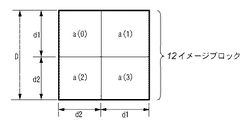
まず、図12に示したように入力画像10を4×4のサブイメージ11(sub-image)に分割する。それぞれのサブイメージを更に所定数に近くなるように正方形のイメージブロック12(image-block)に分割する。次に、イメージブロックを更に4(2×2)つの区画13に分割し、それぞれの区画に対して平均輝度a(0)〜a(3)を求める。次に、図13に示した4つの方向、(a)垂直方向、(b)水平方向、(c)45度方向、(d)135度方向、(e)無方向に対応するフィルタを用いて、それぞれのエッジ強度m_v、m_h、m_d45、m_d135、m_ndを計算する。例えば、m_vは、イメージブロック12の4分割された各区画の平均輝度をa(n)と表現すると次式のようになる(なお、n=0〜3であり、4分割された各区画に付加した番号を示している。
m_v=|1×a(0)+(-1)×a(1)+1×a(2)+(-1)×a(3)| …(1)
First, as shown in FIG. 12, the
m_v = | 1 × a (0) + (-1) × a (1) + 1 × a (2) + (-1) × a (3) | (1)
そして、エッジ強度m_v、m_h、m_d45、m_d135、m_ndの中の最大値が、所定の閾値A以上のとき、その最大値の方向が当該イメージブロックのエッジの方向であると判定する。閾値Aは、エッジが存在しているとみなせる強度の下限値である。サブイメージ11に含まれる各イメージブロック12の方向をカウントすることで、エッジヒストグラムEijが計算される。なお、i=0〜4は図13の(a)〜(e)に示される各フィルタに対応し、j=0〜15は各サブイメージ11に対応する。こうして得られたエッジヒストグラムEijを特徴量とする。
しかしながら、文献1で示されるエッジ抽出方法は、Sobelフィルタなどを用いたエッジ抽出方法に比べて、計算コストが小さいという利点があるものの、エッジ特徴を十分に得ることができない場合がある。特に顕著に表れる例として2値画像の線画を対象とした画像検索に適用した場合について説明する。
However, although the edge extraction method disclosed in
図14(a)に、等間隔の線21を4本と、幅2dの4つのイメージブロックをそれぞれ4分割した計16領域とを重ねて示す。2値画像の線画では、線21に対応した領域で表現されているように、特定の濃度領域を表現するために、直線を等間隔で並べたハッチングが用いられることが多い。このようなハッチングの領域に対して、イメージブロック12のサイズとハッチングの線21の間隔との関係によって、ハッチングが抽出できなくなる場合がある。例えば、図14の(a)に示したように、イメージブロック12のサイズと線21の間隔が同期した場合を考える。イメージブロック12のサイズ(幅および高さ)を2d、線21の太さ(幅)をb、線21と線21の間の隙間をgとして、これらが例えば以下の(2)式の関係にあるとき、式(1)において、a(n)の値がすべて同じ値になる。このため、m_vの値は0になり、明らかにくっきりと縦線が存在しているにもかかわらず、縦線が検出できなくなる。
d=b+g …(2)
FIG. 14A shows four equally
d = b + g (2)
エッジヒストグラムを用いた画像検索を行う場合、データベースに格納されている画像のエッジヒストグラムと、クエリで与える画像のエッジヒストグラムが類似していれば検索ができる。従って、図14の(a)のように線21が存在していても常にエッジを検出できないのであれば、データベースとクエリとでエッジヒストグラムの特徴量が類似する。しかしながら、図14の(b)のように、イメージブロック12のサイズと線21の間隔の同期が少しずれている場合は、そのずれ具合によって、エッジが検出できたりできなかったりする場合がある。例えば、図14の(b)のような関係でイメージブロック12とハッチングの線21が配置された場合を考える。また、イメージブロック12のサイズ(幅および高さ)を2d、イメージブロック12の左端から線21の左端のずれをa、線21の太さをb、線21間の隙間をg、線21の輝度を0、紙白の輝度を255とすると、式(1)の値は、以下のようになる。
When an image search using an edge histogram is performed, the search can be performed if the edge histogram of the image stored in the database is similar to the edge histogram of the image given by the query. Accordingly, as shown in FIG. 14A, if the edge cannot always be detected even if the
a(0)=a(2)=(d−(b−a)×255)/d
a(1)=a(3)=((d−b)×255)/d
m_v=(a×255)/d …(3)
したがって、イメージブロックのサイズがクエリの画像とデータベースの画像とで同じであるとすると、m_vの値は、aの値によって、閾値Aより大きくなったり小さくなったりして、エッジが検出できたりできなかったりする。
a (0) = a (2) = (d− (ba) × 255) / d
a (1) = a (3) = ((db) × 255) / d
m_v = (a × 255) / d (3)
Therefore, if the size of the image block is the same between the query image and the database image, the value of m_v can be larger or smaller than the threshold value A depending on the value of a, and an edge can be detected. There is not.
このような状態は、ハッチングの線21が長ければ、線21の方向に沿って広がっていき、線21の太さや間隔等の条件によっては、線21の鉛直方向に広がっていく。ハッチングは、広い領域に適用される場合も有り、このような場合は、人間にとっては非常に似通った画像であっても、エッジヒストグラムの特徴量は大きく異なることにつながり、結果的に、類似する画像が検索できないという不具合が発生する。
Such a state spreads along the direction of the
本発明は上記の課題に鑑みてなされたものであり、より正確に画像のエッジ特徴量を算出可能な画像処理装置及び方法を提供することを目的とする。 The present invention has been made in view of the above-described problems, and an object thereof is to provide an image processing apparatus and method capable of calculating an edge feature amount of an image more accurately.
上記の目的を達成するための本発明の一態様による画像処理装置は以下の構成を備える。即ち、
画像を複数のイメージブロックへ分割する分割手段と、
前記分割手段で得られたイメージブロックを分割して2次元に配列された所定数の区画を取得する取得手段と、
前記取得手段で取得した前記所定数の前記区画の輝度情報に基づいて前記イメージブロックの画像のエッジ方向を判定する第1判定手段と、
前記第1判定手段でエッジ方向を判定できなかった場合に、前記イメージブロックにおける区画の生成の仕方を変更することにより、前記所定数の変更された区画を生成する生成手段と、
前記生成手段で生成した前記所定数の前記変更された区画の輝度情報に基づいてエッジ方向を判定し、該判定したエッジ方向を前記イメージブロックの画像のエッジ方向とする第2判定手段と、
前記第1判定手段または前記第2判定手段の判定結果にしたがって前記イメージブロックのエッジ方向を決定する決定手段とを備える。
In order to achieve the above object, an image processing apparatus according to an aspect of the present invention has the following arrangement. That is,
A dividing means for dividing the image into a plurality of image blocks;
Obtaining means for dividing the image block obtained by the dividing means to obtain a predetermined number of sections arranged two-dimensionally ;
First determination means for determining an edge direction of an image of the image block based on luminance information of the predetermined number of sections acquired by the acquisition means;
Generating means for generating the predetermined number of changed sections by changing a method of generating the sections in the image block when the edge direction cannot be determined by the first determination section ;
A second judging means for judging an edge direction, the edge direction which has the determined edge direction of the image of the image block based on the changed luminance information section of the predetermined number generated by said generating means,
And a determining means for determining an edge direction determination result thus the image block of the first judging means or the second judging means.
また、上記の目的を達成するための本発明の他の態様による画像処理装置の制御方法は、
分割手段が、画像を複数のイメージブロックへ分割する分割工程と、
取得手段が、前記分割工程で得られたイメージブロックを分割して2次元的に配列された所定数の区画を取得する取得工程と、
第1判定手段が、前記取得工程で取得した前記所定数の前記区画の輝度情報に基づいて前記イメージブロックの画像のエッジ方向を判定する第1判定工程と、
生成手段が、前記第1判定工程でエッジ方向を判定できなかった場合に、前記イメージブロックにおける区画の生成の仕方を変更することにより、前記所定数の変更された区画を生成する生成工程と、
第2判定手段が、前記生成工程で生成した前記所定数の前記変更された区画の輝度情報に基づいてエッジ方向を判定し、該判定したエッジ方向を前記イメージブロックの画像のエッジ方向とする第2判定工程と、
決定手段が、前記第1判定工程または前記第2判定工程の判定結果にしたがって前記イメージブロックのエッジ方向を決定する決定工程とを有する。
In addition, a method for controlling an image processing apparatus according to another aspect of the present invention for achieving the above object is as follows:
A dividing step of dividing the image into a plurality of image blocks;
An obtaining unit that obtains a predetermined number of sections arranged in a two-dimensional manner by dividing the image block obtained in the dividing step;
A first determination step in which a first determination unit determines an edge direction of the image of the image block based on the luminance information of the predetermined number of sections acquired in the acquisition step;
A generation step of generating the predetermined number of changed sections by changing a generation method of the sections in the image block when the generation unit fails to determine the edge direction in the first determination step ;
Second determination means determines an edge direction based on the changed luminance information section of the predetermined number generated in the generating step, the edge direction which is the determination to the edge direction of the image of said
Determining means, and a determination step of determining an edge direction of the first determination step or the second determination step of determining results therefore the image block.
本発明によれば、より正確に画像のエッジ特徴量を算出することができる。また、本発明によれば、イメージブロックを単位としたエッジ方向判定を行なうので、Sobelフィルタなどを用いる手法に比べて高速である。即ち、本発明によれば、高速、且つ、画像検索などに用いるのに十分なエッジ特徴を得ることが可能な画像処理装置及び方法が提供され得る。 According to the present invention, the edge feature amount of an image can be calculated more accurately. In addition, according to the present invention, the edge direction determination is performed in units of image blocks, which is faster than a method using a Sobel filter or the like. That is, according to the present invention, it is possible to provide an image processing apparatus and method capable of obtaining edge features sufficient for use in high-speed image retrieval and the like.
以下、添付の図面を参照して本発明の好適な実施形態について詳細に説明する。以下の実施形態では、画像のエッジ抽出方法を、エッジヒストグラムを特徴量とした画像検索に応用した例で説明する。 Hereinafter, preferred embodiments of the present invention will be described in detail with reference to the accompanying drawings. In the following embodiments, an image edge extraction method will be described with reference to an example in which an image search using an edge histogram as a feature amount is applied.
図1は、本実施形態における画像処理装置100の制御構成を示すブロック図である。図1において、101はCPUであり、本実施形態の画像処理装置100における各種制御を実行する。102はROMであり、本装置の立ち上げ時に実行されるブートプログラムや各種データを格納する。103はRAMであり、CPU101が処理するためのコンピュータプログラムを格納するとともに、CPU101が各種制御を実行する際の作業領域を提供する。104はキーボード、105はマウスであり、ユーザによる各種入力操作環境を提供する。
FIG. 1 is a block diagram illustrating a control configuration of the
106は外部記憶装置であり、ハードディスクやフロッピー(登録商標)ディスク、光ディスク、磁気ディスク、光磁気ディスク、磁気テープ、不揮発性のメモリカード等で構成される。107は表示器であり、ディスプレイなどで構成され、結果等をユーザに対して表示する。108はネットワークインターフェースであり、ネットワーク上の各機器との通信を可能とする。109はIEEE1394、USBなどのインターフェースであり、スキャナ111やデジタルカメラ112などの機器と通信を行う。110はシステムバスであり、上述した各構成を通信可能に接続する。
An
なお、上記の構成において外部記憶装置106、スキャナ111、デジタルカメラ112はネットワーク上に配置されたもので代用されてもよい。
In the above configuration, the
図2は、本実施形態の画像処理装置100によるエッジ抽出及び特徴量算出処理に関する機能構成を示すブロック図である。
FIG. 2 is a block diagram illustrating a functional configuration related to edge extraction and feature amount calculation processing by the
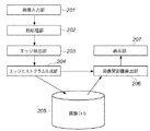
図2において、201は画像入力部であり、スキャナ111やデジタルカメラ112などの機器で取得した画像をインターフェース109を介して、或いは、インターネット上やLAN上に存在する画像をネットワークインターフェース108を介して入力する。202は前処理部であり、入力された画像に対して必要な前処理を行う。203はエッジ抽出部であり、前処理部202による前処理後の画像に対してエッジ抽出処理を行う。204はヒストグラム生成部であり、エッジ抽出部203によるエッジ抽出結果に基づいてエッジ方向の出現頻度を表すエッジヒストグラムを生成する。205は画像データベースであり、入力された画像とエッジヒストグラムを関連付けて記憶・管理する。206は画像間距離算出部であり、検索時に画像データベース205中の画像のエッジヒストグラムと、検索元として入力された画像のエッジヒストグラムの距離を算出する。207は表示部であり、画像間距離算出部206による距離の算出結果に基づいて、ユーザに対して検索結果の画像の表示を行う。上述した各部はCPU101がROM102に格納されたコンピュータプログラム或は外部記憶装置106からRAM103にロードされたコンピュータプログラムを実行することにより実現される。
In FIG. 2,
[登録処理]
まず、画像処理装置100への画像の登録処理について、図3のフローチャートを用いて説明する。
[registration process]
First, image registration processing in the
まず、ステップS301において、画像入力部201は、ネットワークインターフェース108やインターフェース109を介して登録対象の画像を入力する。次に、ステップS302において前処理部202は、入力画像がカラーかグレースケールかを判定する。入力画像がカラーの場合は、ステップS203において、前処理部202は、当該入力画像をグレースケールに変換する。尚、カラーかグレースケールかの判定は、デジタルカメラ112から画像を取得した場合などでは、画像のデータフォーマットを解析し、そのヘッダ情報を参照することで判定できる。また、スキャナ111から画像を取得した場合などでは、ユーザによって設定されたスキャン条件から判定できる。又、ステップS303におけるカラーからグレースケールへの変換は、例えば以下の(4)式により、カラー画像データの各画素のR(赤)、G(緑)、B(青)の値をグレースケールの信号(Y)へ変換することにより行われる。
First, in step S301, the
Y=0.299×R+0.587×G+0.114×B …(4)
次に、ステップS304においてエッジ抽出部203は、入力画像に対してエッジの抽出を行う。エッジ抽出の処理の詳細は後述する。次に、ステップS305においてエッジヒストグラム生成部204は、ステップS305で抽出されたエッジを集計し、図12、図13により上述したようにエッジヒストグラムEijを生成する。次に、ステップS306においてエッジヒストグラム生成部204は、生成したエッジヒストグラムEijをインデックスとして画像と関連付けて画像データベース205に記憶する。
Y = 0.299 × R + 0.587 × G + 0.114 × B (4)
Next, in step S304, the
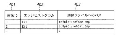
図4は、エッジヒストグラムによるインデックスの例である。画像ID401は、登録される画像にふられたID(識別子)である。エッジヒストグラム402は、対応する画像のエッジヒストグラムEijである。画像ファイルへのパス403は、登録された画像ファイルへのパス情報であり、これを参照することで、画像データの本体を読み出すことができる。
FIG. 4 is an example of an index based on an edge histogram. An
[エッジ抽出処理]
エッジ抽出処理の詳細について、図5のフローチャートを用いて説明する。
[Edge extraction processing]
Details of the edge extraction processing will be described with reference to the flowchart of FIG.
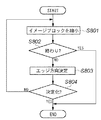
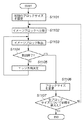
まず、ステップS501において、エッジ抽出部203は、入力画像をイメージブロックに分割する。これは、図12により上述したように、4x4のサブイメージ11中に所定数に近い数の正方形のイメージブロック12を確保するように分割することである。ここで「所定数」は特に限定されるものではないが、後にイメージブロックに対して2×2のフィルタ処理を施すことになるので、正方形の一辺は、2画素以上であり、かつ、偶数でなければならない。すなわち、ステップS501において、画像が当該画像の部分領域である複数のイメージブロックへ分割される。本願では、このステップS501で得られた複数のイメージブロックを第1のイメージブロックと称する。複数の第1のイメージブロックの各々からは、イメージブロックの画像のエッジ方向を判定するフィルタに対応した複数の区画が取得される。
First, in step S501, the
次に、ステップS502において、イメージブロックを一つずつ順番に取り出す。全てのイメージブロックについて処理を終えた場合は、ステップS503から本エッジ抽出処理を終了する。未処理のイメージブロックが取り出された場合は、ステップS503からステップS504へ処理が進む。 Next, in step S502, image blocks are taken out one by one. When the processing has been completed for all the image blocks, the edge extraction processing ends from step S503. If an unprocessed image block is extracted, the process proceeds from step S503 to step S504.
ステップS504において、上記取得された複数の区画とフィルタに基づいて第1のイメージブロックの画像のエッジ方向が判定される(第1判定処理)。すなわち、対象のイメージブロックに対して、図13に示した4つの方向と無方向のフィルタを掛け、それぞれのエッジ強度(m_v、m_h、m_d45、m_d135、m_nd)を求める。そして、求めたエッジ強度のうちの最大のエッジ強度に閾値A以上であれば、そのエッジ強度に対応する方向を当該イメージブロック12の方向として決定し、方向とエッジ強度をRAM103に一時保存する。一方、最大のエッジ強度が閾値A未満であれば、エッジの方向は決定できないままである。このとき、当該イメージブロック12の平均輝度をRAM103に一時保存しておく。(1)式に示したように、エッジ強度を求める際に、イメージブロックの4分割された各小領域の平均輝度(a(0)〜a(3))を求めてあるので、イメージブロック12の平均輝度は少ない処理コストで求めることができる。
In step S504, the edge direction of the image of the first image block is determined based on the acquired plurality of sections and filters (first determination process). That is, the target image block is subjected to the four direction and non-directional filters shown in FIG. 13 to obtain respective edge strengths (m_v, m_h, m_d45, m_d135, m_nd). If the maximum edge strength of the obtained edge strengths is equal to or greater than the threshold A, the direction corresponding to the edge strength is determined as the direction of the
ステップS504においてエッジの方向が決定できた場合は、ステップS505からステップS502に戻る。一方、ステップS504においてエッジの方向が決定できなかった場合は、ステップS505からステップS506へ進む。 If the edge direction can be determined in step S504, the process returns from step S505 to step S502. On the other hand, if the edge direction cannot be determined in step S504, the process proceeds from step S505 to step S506.
ステップS506において、エッジ抽出部203は、処理対象のイメージブロック12に対して、エッジの抽出漏れが発生したかどうかを判定する。エッジ抽出漏れの判定は図6の参照により後述する。ステップS506において抽出漏れが発生していると判定された場合、処理はステップS507へ進む。ステップS507において、エッジ抽出部203は、対象のイメージブロック12のエッジの方向を補正処理によって決定しなおす(方向決定補正処理)。なお、このステップS507においてなされるエッジ方向の判定を、上記第1判定処理に対して第2判定処理ともいう。また、ステップS506による判定処理は、第1判定手段でエッジ方向を判定できなかった場合に、第1のイメージブロックの輝度分布等に基づいて、イメージブロックにおけるエッジの存在の可能性を判定する第3判定処理であり、第3判定処理ともいう。そして、処理はステップS502に戻る。この補正処理の詳細は、図8の参照により後述する。尚、ステップS506においてエッジの抽出漏れは発生していないと判定された場合には、処理はそのままステップS502へ戻る。
In step S506, the
続いて、ステップS506によるエッジ抽出漏れの判定処理の詳細を、図6のフローチャートを用いて説明する。 Next, details of the edge extraction omission determination process in step S506 will be described with reference to the flowchart of FIG.
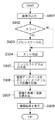
ステップS601において、エッジ抽出部203は、処理対象のイメージブロック12の平均輝度値が所定の値よりも大きいかどうかを判定する。本発明が解決しようとしている課題は、主に線画において発生し、線画の背景が白地である場合が多く、また、線画では、線分が存在しないイメージブロックも多数存在する可能性が高い。そこで、本実施形態では、処理対象のイメージブロックの平均輝度が所定の値よりも大きければ、線分が存在しない、或は、エッジが少ないイメージブロックであると判断する。即ち、平均輝度が所定の値よりも大きければ、エッジの抽出漏れはないとして本処理を終了する。これにより、線分が少ないイメージブロックに不必要な補正処理を行ってしまうことを防止でき、エッジ抽出処理の高速化を図ることができる。一方、ステップS601においてイメージブロック12の平均輝度値が所定の値以下の場合はステップS602へ進む。
In step S601, the
ステップS602において、エッジ抽出部203は、複数の当該イメージブロック12に線分が存在しているかどうかを判定するために、複数の当該イメージブロック12に関して輝度ヒストグラムを生成する。この輝度ヒストグラムの生成では、ステップS504で求めた当該イメージブロック12の平均輝度が用いられる。ヒストグラムの生成について以下により詳細に説明する。
In step S <b> 602, the
イメージブロック12の輝度ヒストグラムは、線分が存在しない場合には、一様な図7の(a)に示されるような分布を取ると思われる。しかしながら、図14に示したようにイメージブロック12内に線分が存在する場合には、図7の(b)に示されるように、平均輝度の度数よりも平均輝度の両側の極大値の度数の方が大きくなる。線の太さによりどちらかの山が高くなることもある。したがって、本実施形態では、図7の(c)に示されるように、ビン数を3とし、ビンの境界を平均輝度から所定の値Wを引いた値と、平均輝度に所定の値Wを加えた値として輝度ヒストグラムを生成する。このような輝度ヒストグラムによれば、図7の(a)と(b)の違いを容易に判定できるようになる。
The luminance histogram of the
ステップS603において、エッジ抽出部203は、ステップS602で生成した輝度ヒストグラムを用いてエッジの抽出漏れが発生したかどうかを判定する。本実施形態では、エッジ抽出部203は、平均輝度に対応したビンの度数の値が、他の2つのビンのどちらの値よりも所定の値Z以上に小さければ抽出漏れが発生したと判断し、そうでなければ、抽出漏れは発生していないと判断する。このように、エッジの抽出漏れが発生しているかどうかを、ステップS507の補正処理を行う前に行うことにより、エッジ漏れの発生していないイメージブロックに対して補正処理が実行されてしまうことを防止できる。後述のように、ステップS507の補正処理はイメージブロックのサイズを変えて何度もエッジの方向決定処理を試みるため、無駄な補正処理を省くことは、処理速度の向上に著しく貢献する。
In step S603, the
続いて、ステップS507による補正処理の詳細を、図8のフローチャートを用いて説明する。補正処理では、上記第1のイメージブロックについて取得された複数の区画とは大きさが異なる複数の区画から構成される第2のイメージブロックが生成され、これら複数の区画とフィルタに基づいて第2のイメージブロックの画像のエッジ方向が判定される。 Next, details of the correction processing in step S507 will be described with reference to the flowchart of FIG. In the correction process, a second image block including a plurality of sections having different sizes from the plurality of sections acquired for the first image block is generated, and a second image block is generated based on the plurality of sections and the filter. The edge direction of the image of the image block is determined.
ステップS801において、エッジ抽出部203は、対象のイメージブロック12に対して、当該イメージブロック12の高さと幅を2画素ずつ減らしていく。こうして、ステップS501で取得された複数の区画とは大きさの異なる複数の区画が取得されることになる。図15を見れば明らかなように、イメージブロックの大きさを徐々に小さくしていけば、ハッチングに対してエッジが抽出できていない場合でも、いつかはエッジが抽出できるようになる。例えば、図15の(a)に示されるように線21とイメージブロック12が配置されていると、上下左右の区画に平均輝度値の差が発生しないのでエッジは検出されない。図15の(b)に示されるように、元のイメージブロック12から縦横2画素を減少させても、上下左右の区画に平均輝度値の差は生じない。これに対して、図15の(c)に示されるように、元のイメージブロック12の大きさを縦横4画素ずつ減少させると、左右の区画で平均輝度値に差が生じ、縦方向のエッジが検出されることになる。
In step S <b> 801, the
次に、ステップS802において、エッジ抽出部203は、イメージブロックのサイズに応じて分岐する。処理時のイメージブロックのサイズが、初めのイメージブロックのサイズより所定の割合以下になったかどうかで分岐する。例えば、イメージブロックのサイズが元のサイズの2分の1よりも小さくなれば、エッジは抽出できなかったものとして、RAM103にエッジがないということを一時保存し処理を終了する。イメージブロックのサイズが元のサイズの2分の1以上であれば処理はステップS803へ進む。
Next, in step S802, the
ステップS803において、エッジ抽出部203は、エッジの方向を決定する(第2判定処理。この処理はステップS504と同じ処理である。そして、ステップS804において、エッジ抽出部203は、ステップS803においてエッジの方向が決定できたかどうかを判定する。エッジの方向が決定できていない場合は、処理はステップS801へ戻り、決定できていれば、処は終了する。以上のようにして、イメージブロックのサイズを徐々に縮小してエッジの方向を決定することによって、ハッチングなどに対してステップS504で決定できなかったエッジの方向を決定して補正することができる。
In step S803, the
尚、上記の処理では、ステップS506の第3判定処理で抽出漏れありと判定された場合にのみステップS507の方向決定処理が行われるが、これに限られるものではない。例えば、ステップS506の判定を行わずに、ステップS507の方向決定補正処理を必ず実行するようにしてもよい。この場合、例えば、イメージブロックのサイズを変更することにより得られた複数種類のエッジ方向判定結果から、最もエッジ強度の強いエッジ方向判定結果を採用する。以上のように、本実施形態によれば、第1判定処理と第2判定処理の少なくともいずれかによって判定されたエッジ方向に基づいて画像に含まれる部分領域のエッジ方向が決定される。 In the above process, the direction determination process in step S507 is performed only when it is determined that there is an omission in the third determination process in step S506, but the present invention is not limited to this. For example, the direction determination correction process in step S507 may be executed without performing the determination in step S506. In this case, for example, an edge direction determination result having the strongest edge strength is adopted from a plurality of types of edge direction determination results obtained by changing the size of the image block. As described above, according to the present embodiment, the edge direction of the partial region included in the image is determined based on the edge direction determined by at least one of the first determination process and the second determination process.
[検索処理]
画像処理装置100による検索処理について、図9のフローチャートを用いて説明する。
[Search processing]
Search processing by the
まず、ステップS901〜S905において、画像入力部201により検索元画像を入力し、前処理部202、エッジ抽出部203、エッジヒストグラム生成部204によりエッジヒストグラムを生成する。ここまでの処理は、図3の登録処理におけるステップS301〜ステップS305と同じである。
First, in steps S901 to S905, a search source image is input by the
次に、ステップS906において、画像間距離算出部206は、画像データベース205内の各画像のエッジヒストグラムを順に読み出し、検索元画像のエッジヒストグラムとの距離を算出する。具体的には、例えば、エッジヒストグラムEijの各ビンの差分の絶対値の総和を算出する。算出された距離が小さいほど両画像が類似していることになり、最も距離が小さいものが第1候補となる。このように算出された距離と検索先画像のIDのリストをRAM103に一時保存する。
Next, in step S <b> 906, the inter-image
次に、ステップS907において画像間距離算出部206は、ステップS907で取得したリストを距離の昇順にソートした後、順に画像IDからインデックスを参照して画像を画像データベース205より読み出し、縮小してサムネイル画像とする。
Next, in step S907, the inter-image
次に、ステップS908において、表示部207は検索結果を表示する。より具体的には、表示部207は、ステップS907で取得されたサムネイル画像を距離と共にマトリックス上に並べて表示する。例えば、第1候補から順に列の左から右へ、上の列から下の列へ並べて表示する。ユーザはこれにより所望の画像が得られたかを確認することができる。
Next, in step S908, the
[他の実施形態]
上記実施形態においては、画像検索に用いられる特徴量として文献1に記載されているエッジヒストグラムを使用したが、もちろん、これに限定されるものではない。例えば、無方向フィルタを用いず、方向フィルタのみを用いるようにしてもよい。また、式(1)では、エッジの向きの違いは考慮していない(絶対値をとっている)が、式(1)においてプラスの値とマイナスの値を別々に扱うようにして、向きの違いを考慮するようにしてもよい。また、方向フィルタを5つ以上用いてもよい。例えば、図13に示した(a)〜(d)の方向フィルタに、22.5度、67.5度、112.5度、157.5度を加えた8つの方向フィルタを用いてもよい。
[Other embodiments]
In the above-described embodiment, the edge histogram described in
また、上記実施形態では、エッジの抽出漏れが発生し、エッジの方向決定を補正するために、ステップS901に示したように、イメージブロックのサイズを縮小して補正していたが、これに限られるものではない。例えば、イメージブロックのサイズを拡大して補正を行うようにしてもよく、このような手法でもハッチングなどに対してエッジが抽出できるようになる。また、イメージブロックのサイズを変えるのではなく、図10に示すように、イメージブロック中の区画のサイズを変えるようにしてもよい。すなわち、図10に示されるように、d2の値を小さくし、d1の値を大きくするといったように、分割の比率を変更することにより、イメージブロック12内の区画の形状が変更される。このように区画の形状を変更して上記フィルタによるエッジ方向検出を行なうことにより、ハッチングなどに関連したエッジを抽出できるようになる。即ち、上記実施形態によれば、イメージブロックから取得される複数の区画の画素構成を異ならせて変更された複数の区画を取得し、新たな複数の区画についてフィルタによるエッジ方向検出を行なうことにより、線分の検出漏れが防止されるのである。
Further, in the above-described embodiment, edge extraction omission occurs, and correction is performed by reducing the size of the image block as shown in step S901 in order to correct the determination of the edge direction. It is not something that can be done. For example, the correction may be performed by enlarging the size of the image block, and an edge can be extracted for hatching or the like by such a method. Further, instead of changing the size of the image block, as shown in FIG. 10, the size of the section in the image block may be changed. That is, as shown in FIG. 10, by changing the division ratio such that the value of d2 is decreased and the value of d1 is increased, the shape of the partition in the
また、上記実施形態では、エッジ抽出漏れと判定されたイメージブロックに対してエッジ方向決定の補正を行っていたが、複数種類のイメージブロックで複数のエッジヒストグラムを生成し、度数の大きいエッジヒストグラムを採用するようにしてもよい。例えば、最初のイメージブロックのサイズでエッジヒストグラムを生成した後、イメージブロックのサイズを段階的に小さくしていって、エッジヒストグラムを再生成する。こうして得られた複数のエッジヒストグラムの中から、サブイメージに対する各方向の度数の大きいほうを採用する。尚、異なるサイズのイメージブロック(即ち、異なる個数のサブイメージ内のイメージブロック)に対するエッジヒストグラムの度数を比較する場合、当然のことながら、度数はイメージブロックの個数で正規化を行っておく必要がある。 In the above embodiment, the edge direction determination correction is performed on the image block determined to be the edge extraction omission, but a plurality of edge histograms are generated with a plurality of types of image blocks, and the edge histogram having a high frequency is generated. You may make it employ | adopt. For example, after the edge histogram is generated with the size of the first image block, the size of the image block is gradually reduced, and the edge histogram is regenerated. Of the plurality of edge histograms obtained in this way, the one with the higher frequency in each direction with respect to the sub-image is adopted. It should be noted that when comparing the frequency of edge histograms for image blocks of different sizes (that is, image blocks in different numbers of sub-images), the frequency must naturally be normalized by the number of image blocks. is there.
図11は、上記複数のエッジヒストグラムを生成する場合の処理を説明するフローチャートである。エッジ抽出部203は、ステップS1101において、初期のイメージブロックサイズを設定する。ステップS1102において、エッジ抽出部203は、設定されたブロックサイズのイメージブロックへ入力画像を分割する。ステップS1102〜S1105は図5ステップS501〜S504と同様である。ステップS1104で全てのイメージブロックについて処理を終えたと判定されると、処理はステップS1106へ進む。ステップS1106においてエッジ抽出部203は、イメージブロックのブロックサイズを変更する。例えば、縦横に2画素ずつ小さいイメージブロックのサイズを設定する。予め用意した全てのブロックサイズについて処理を終えている場合は、ステップS1107から本処理を終了する。未処理のブロックサイズがあれば、処理をステップS1102に戻し、当該変更されたブロックサイズのイメージブロックへ分割してエッジ方向の決定を行う。ステップS305では、こうして、複数のイメージブロックのサイズに対応したエッジ抽出結果から度数の大きいエッジヒストグラムが選択され、当該入力画像のエッジヒストグラムとして採用される。
FIG. 11 is a flowchart for explaining processing when generating the plurality of edge histograms. In step S1101, the
また、上記実施形態では、ステップS601に示すように、イメージブロックの平均輝度が大きい場合にエッジの抽出漏れ無しと判定していたが、イメージブロックの平均輝度が所定閾値よりも小さい場合にもエッジの抽出漏れ無しと判定するようにしてもよい。また、上記実施形態では、ステップS602に示したように、イメージブロックの平均を中心とした輝度ヒストグラムを用いてエッジの抽出漏れを判定していたがこれに限られるものではない。例えば、イメージブロック内の輝度の分散を求めて、分散が所定の値よりも大きければエッジの抽出漏れありと判定するようにしてもよい。即ち、イメージブロック内の輝度分布(輝度ヒストグラムや輝度の分散)に基づいてエッジの存在の可能性が判定される。 In the above embodiment, as shown in step S601, it is determined that there is no omission of edge extraction when the average luminance of the image block is large, but the edge is also detected when the average luminance of the image block is smaller than a predetermined threshold. It may be determined that there is no extraction omission. In the above embodiment, as shown in step S602, the edge extraction omission is determined using the luminance histogram centered on the average of the image blocks. However, the present invention is not limited to this. For example, the luminance variance in the image block may be obtained, and if the variance is larger than a predetermined value, it may be determined that there is an edge extraction omission. That is, the possibility of the presence of an edge is determined based on the luminance distribution (luminance histogram and luminance dispersion) in the image block.
以上説明したように、上記実施形態によれば、Sobelフィルタなどを用いる手法に比べて高速であり、かつ、ハッチング等に対してエッジの抽出漏れを回避したエッジ抽出が可能となり、エッジ特徴を利用した画像検索の高精度化を図ることができる。 As described above, according to the above-described embodiment, edge extraction can be performed at a higher speed than a method using a Sobel filter and avoiding edge extraction omission for hatching and the like, and edge features are used. It is possible to improve the accuracy of the image search.
以上、実施形態を詳述したが、本発明は、例えば、システム、装置、方法、プログラムもしくは記憶媒体等としての実施態様をとることが可能である。具体的には、複数の機器から構成されるシステムに適用しても良いし、また、一つの機器からなる装置に適用しても良い。 Although the embodiment has been described in detail above, the present invention can take an embodiment as a system, apparatus, method, program, storage medium, or the like. Specifically, the present invention may be applied to a system composed of a plurality of devices, or may be applied to an apparatus composed of a single device.
尚、本発明は、ソフトウェアのプログラムをシステム或いは装置に直接或いは遠隔から供給し、そのシステム或いは装置のコンピュータが該供給されたプログラムコードを読み出して実行することによって前述した実施形態の機能が達成される場合を含む。この場合、供給されるプログラムは実施形態で図に示したフローチャートに対応したプログラムである。 In the present invention, the functions of the above-described embodiments are achieved by supplying a software program directly or remotely to a system or apparatus, and the computer of the system or apparatus reads and executes the supplied program code. Including the case. In this case, the supplied program is a program corresponding to the flowchart shown in the drawing in the embodiment.
従って、本発明の機能処理をコンピュータで実現するために、該コンピュータにインストールされるプログラムコード自体も本発明を実現するものである。つまり、本発明は、本発明の機能処理を実現するためのコンピュータプログラム自体も含まれる。 Accordingly, since the functions of the present invention are implemented by computer, the program code installed in the computer also implements the present invention. In other words, the present invention includes a computer program itself for realizing the functional processing of the present invention.
その場合、プログラムの機能を有していれば、オブジェクトコード、インタプリタにより実行されるプログラム、OSに供給するスクリプトデータ等の形態であっても良い。 In that case, as long as it has the function of a program, it may be in the form of object code, a program executed by an interpreter, script data supplied to the OS, or the like.
プログラムを供給するためのコンピュータ可読記憶媒体としては以下が挙げられる。例えば、フロッピー(登録商標)ディスク、ハードディスク、光ディスク、光磁気ディスク、MO、CD−ROM、CD−R、CD−RW、磁気テープ、不揮発性のメモリカード、ROM、DVD(DVD−ROM,DVD−R)などである。 Examples of the computer-readable storage medium for supplying the program include the following. For example, floppy (registered trademark) disk, hard disk, optical disk, magneto-optical disk, MO, CD-ROM, CD-R, CD-RW, magnetic tape, nonvolatile memory card, ROM, DVD (DVD-ROM, DVD- R).
その他、プログラムの供給方法としては、クライアントコンピュータのブラウザを用いてインターネットのホームページに接続し、該ホームページから本発明のコンピュータプログラムをハードディスク等の記録媒体にダウンロードすることが挙げられる。この場合、ダウンロードされるプログラムは、圧縮され自動インストール機能を含むファイルであってもよい。また、本発明のプログラムを構成するプログラムコードを複数のファイルに分割し、それぞれのファイルを異なるホームページからダウンロードすることによっても実現可能である。つまり、本発明の機能処理をコンピュータで実現するためのプログラムファイルを複数のユーザに対してダウンロードさせるWWWサーバも、本発明に含まれるものである。 As another program supply method, a client computer browser is used to connect to a homepage on the Internet, and the computer program of the present invention is downloaded from the homepage to a recording medium such as a hard disk. In this case, the downloaded program may be a compressed file including an automatic installation function. It can also be realized by dividing the program code constituting the program of the present invention into a plurality of files and downloading each file from a different homepage. That is, a WWW server that allows a plurality of users to download a program file for realizing the functional processing of the present invention on a computer is also included in the present invention.
また、本発明のプログラムを暗号化してCD−ROM等の記憶媒体に格納してユーザに配布するという形態をとることもできる。この場合、所定の条件をクリアしたユーザに、インターネットを介してホームページから暗号を解く鍵情報をダウンロードさせ、その鍵情報を使用して暗号化されたプログラムを実行し、プログラムをコンピュータにインストールさせるようにもできる。 Further, the program of the present invention may be encrypted, stored in a storage medium such as a CD-ROM, and distributed to users. In this case, a user who has cleared a predetermined condition is allowed to download key information for decryption from a homepage via the Internet, execute an encrypted program using the key information, and install the program on the computer. You can also.
また、コンピュータが、読み出したプログラムを実行することによって、前述した実施形態の機能が実現される他、そのプログラムの指示に基づき、コンピュータ上で稼動しているOSなどとの協働で実施形態の機能が実現されてもよい。この場合、OSなどが、実際の処理の一部または全部を行ない、その処理によって前述した実施形態の機能が実現される。 In addition to the functions of the above-described embodiment being realized by the computer executing the read program, the embodiment of the embodiment is implemented in cooperation with an OS or the like running on the computer based on an instruction of the program. A function may be realized. In this case, the OS or the like performs part or all of the actual processing, and the functions of the above-described embodiments are realized by the processing.
さらに、記録媒体から読み出されたプログラムが、コンピュータに挿入された機能拡張ボードやコンピュータに接続された機能拡張ユニットに備わるメモリに書き込まれて前述の実施形態の機能の一部或いは全てが実現されてもよい。この場合、機能拡張ボードや機能拡張ユニットにプログラムが書き込まれた後、そのプログラムの指示に基づき、その機能拡張ボードや機能拡張ユニットに備わるCPUなどが実際の処理の一部または全部を行なう。 Furthermore, the program read from the recording medium is written in a memory provided in a function expansion board inserted into the computer or a function expansion unit connected to the computer, so that part or all of the functions of the above-described embodiments are realized. May be. In this case, after a program is written in the function expansion board or function expansion unit, the CPU or the like provided in the function expansion board or function expansion unit performs part or all of the actual processing based on the instructions of the program.
Claims (13)
前記分割手段で得られたイメージブロックを分割して2次元に配列された所定数の区画を取得する取得手段と、
前記取得手段で取得した前記所定数の前記区画の輝度情報に基づいて前記イメージブロックの画像のエッジ方向を判定する第1判定手段と、
前記第1判定手段でエッジ方向を判定できなかった場合に、前記イメージブロックにおける区画の生成の仕方を変更することにより、前記所定数の変更された区画を生成する生成手段と、
前記生成手段で生成した前記所定数の前記変更された区画の輝度情報に基づいてエッジ方向を判定し、該判定したエッジ方向を前記イメージブロックの画像のエッジ方向とする第2判定手段と、
前記第1判定手段または前記第2判定手段の判定結果にしたがって前記イメージブロックのエッジ方向を決定する決定手段とを備えることを特徴とする画像処理装置。 A dividing means for dividing the image into a plurality of image blocks;
Obtaining means for dividing the image block obtained by the dividing means to obtain a predetermined number of sections arranged two-dimensionally ;
First determination means for determining an edge direction of an image of the image block based on luminance information of the predetermined number of sections acquired by the acquisition means;
Generating means for generating the predetermined number of changed sections by changing a method of generating the sections in the image block when the edge direction cannot be determined by the first determination section ;
A second judging means for judging an edge direction, the edge direction which has the determined edge direction of the image of the image block based on the changed luminance information section of the predetermined number generated by said generating means,
The image processing apparatus characterized by comprising determination means for determining an edge direction determination result thus the image block of the first judging means or the second judging means.
前記第3判定手段で前記イメージブロックにエッジの存在する可能性があると判定された場合に、前記生成手段と前記第2判定手段による処理を実行させる制御手段とを更に備えることを特徴とする請求項1乃至3の何れか1項に記載の画像処理装置。 Third determination means for determining the presence of an edge in the image block based on a luminance histogram of all images in the image block when the edge direction cannot be determined by the first determination means;
And a control means for executing processing by the generation means and the second determination means when the third determination means determines that there is a possibility that an edge exists in the image block. The image processing apparatus according to claim 1.
前記複数のサブイメージの各々について、前記決定手段によって決定された各イメージブロックのエッジ方向のヒストグラムを生成して、前記入力された画像の特徴量とする特徴量生成手段を更に備えることを特徴とする請求項1乃至4の何れか1項に記載の画像処理装置。 The dividing unit divides an input image into a plurality of sub-images, further divides each of the plurality of sub-images to obtain the plurality of image blocks,
For each of the plurality of sub-images, the image processing apparatus further includes a feature amount generation unit that generates a histogram in the edge direction of each image block determined by the determination unit and sets the histogram as the feature amount of the input image. The image processing apparatus according to any one of claims 1 to 4.
分割手段が、画像を複数のイメージブロックへ分割する分割工程と、
取得手段が、前記分割工程で得られたイメージブロックを分割して2次元的に配列された所定数の区画を取得する取得工程と、
第1判定手段が、前記取得工程で取得した前記所定数の前記区画の輝度情報に基づいて前記イメージブロックの画像のエッジ方向を判定する第1判定工程と、
生成手段が、前記第1判定工程でエッジ方向を判定できなかった場合に、前記イメージブロックにおける区画の生成の仕方を変更することにより、前記所定数の変更された区画を生成する生成工程と、
第2判定手段が、前記生成工程で生成した前記所定数の前記変更された区画の輝度情報に基づいてエッジ方向を判定し、該判定したエッジ方向を前記イメージブロックの画像のエッジ方向とする第2判定工程と、
決定手段が、前記第1判定工程または前記第2判定工程の判定結果にしたがって前記イメージブロックのエッジ方向を決定する決定工程とを有することを特徴とする画像処理装置の制御方法。 A control method for an image processing apparatus, comprising:
A dividing step of dividing the image into a plurality of image blocks;
An obtaining unit that obtains a predetermined number of sections arranged in a two-dimensional manner by dividing the image block obtained in the dividing step;
A first determination step in which a first determination unit determines an edge direction of the image of the image block based on the luminance information of the predetermined number of sections acquired in the acquisition step;
A generation step of generating the predetermined number of changed sections by changing a generation method of the sections in the image block when the generation unit fails to determine the edge direction in the first determination step ;
Second determination means determines an edge direction based on the changed luminance information section of the predetermined number generated in the generating step, the edge direction which is the determination to the edge direction of the image of said image block 2 determination steps;
Determining means, the control method of the image processing apparatus characterized by having a determining step of determining an edge direction of the first determination step or the second determination step of determining results therefore the image block.
制御手段が、前記第3判定工程で前記イメージブロックにエッジの存在する可能性があると判定された場合に、前記生成工程と前記第2判定工程による処理を実行させる制御工程とを更に備えることを特徴とする請求項6乃至8の何れか1項に記載の画像処理装置の制御方法。 When the edge direction cannot be determined in the first determination step, a third determination unit determines the possibility of the presence of an edge in the image block based on the luminance histogram of all the images in the image block. A determination process;
The control means further includes a control step for executing the processing in the generation step and the second determination step when it is determined in the third determination step that there is a possibility that an edge exists in the image block. The method for controlling an image processing apparatus according to claim 6, wherein:
特徴量生成手段が、前記複数のサブイメージの各々について、前記決定工程によって決定された各イメージブロックのエッジ方向のヒストグラムを生成して、前記入力された画像の特徴量とする特徴量生成工程を更に有することを特徴とする請求項6乃至9の何れか1項に記載の画像処理装置の制御方法。 In the dividing step, the input image is divided into a plurality of sub-images, and each of the plurality of sub-images is further divided to obtain the plurality of image blocks,
A feature amount generating unit generates a histogram in the edge direction of each image block determined by the determination step for each of the plurality of sub-images, and sets the feature amount of the input image as a feature amount generation step. The method for controlling an image processing apparatus according to claim 6, further comprising :
前記分割手段で得られたイメージブロックを分割して2次元に配列された所定数の区画からなる区画集合を取得する取得手段と、
前記取得手段で取得した前記複数の区画集合のそれぞれについて、区画の輝度情報に基づいてエッジ方向を判定することにより、各サブイメージについてエッジ方向のヒストグラムを生成する判定手段と、
前記分割手段による前記サブイメージの分割の仕方を変えて異なるサイズの複数のイメージブロックを生成させ、前記判定手段にエッジ方向のヒストグラムを生成させることにより、複数のヒストグラムを生成する生成手段と、
前記生成手段により生成された複数のヒストグラムのうち、最も度数の大きいヒストグラムを対応するサブイメージのエッジヒストグラムとする決定手段とを備えることを特徴とする画像処理装置。 Dividing means for dividing an image into a plurality of sub-images and dividing each sub-image into a plurality of image blocks;
Obtaining means for dividing the image block obtained by the dividing means to obtain a set of partitions composed of a predetermined number of partitions arranged two-dimensionally;
A determination unit that generates an edge direction histogram for each sub-image by determining an edge direction based on luminance information of a partition for each of the plurality of partition sets acquired by the acquisition unit;
Generating means for generating a plurality of histograms by generating a plurality of image blocks of different sizes by changing a way of dividing the sub-image by the dividing means, and generating a histogram of edge directions in the determination means;
An image processing apparatus comprising: a determining unit that sets a histogram having the highest frequency among the plurality of histograms generated by the generating unit as an edge histogram of a corresponding sub-image .
分割手段が、画像を複数のサブイメージへ分割し、各サブイメージを複数のイメージブロックへ分割する分割工程と、
取得手段が、前記分割工程で得られたイメージブロックを分割して2次元に配列された所定数の区画からなる区画集合を取得する取得工程と、
判定手段が、前記取得工程で取得された前記複数の区画集合のそれぞれについて、区画の輝度情報に基づいてエッジ方向を判定することにより、各サブイメージについてエッジ方向のヒストグラムを生成する判定工程と、
生成手段が、前記サブイメージの分割の仕方を変えて異なるサイズの複数のイメージブロックを前記分割工程に生成させ、前記判定工程にエッジ方向のヒストグラムを生成させることにより、複数のヒストグラムを生成する生成工程と、
決定手段が、前記生成工程で生成された複数のヒストグラムのうち、最も度数の大きいヒストグラムを対応するサブイメージのエッジヒストグラムとする決定工程とを有することを特徴とする画像処理装置の制御方法。 A control method for an image processing apparatus, comprising:
A dividing step of dividing the image into a plurality of sub-images and dividing each sub-image into a plurality of image blocks;
An obtaining unit that obtains a set of partitions including a predetermined number of partitions arranged in a two-dimensional manner by dividing the image block obtained in the dividing step;
A determination step for generating a histogram of the edge direction for each sub-image by determining an edge direction based on luminance information of the partition for each of the plurality of partition sets acquired in the acquisition step;
Generating means for generating a plurality of histograms by causing the dividing step to generate a plurality of image blocks of different sizes by changing the way of dividing the sub-image, and generating a histogram in the edge direction in the determination step. Process,
And a determining unit that determines a histogram having the highest frequency among the plurality of histograms generated in the generating step as an edge histogram of a corresponding sub-image .
Priority Applications (3)
| Application Number | Priority Date | Filing Date | Title |
|---|---|---|---|
| JP2007105250A JP4898531B2 (en) | 2007-04-12 | 2007-04-12 | Image processing apparatus, control method therefor, and computer program |
| US12/060,838 US8064705B2 (en) | 2007-04-12 | 2008-04-01 | Image processing apparatus and control method thereof |
| CN2008100899498A CN101286230B (en) | 2007-04-12 | 2008-04-11 | Image processing apparatus and method thereof |
Applications Claiming Priority (1)
| Application Number | Priority Date | Filing Date | Title |
|---|---|---|---|
| JP2007105250A JP4898531B2 (en) | 2007-04-12 | 2007-04-12 | Image processing apparatus, control method therefor, and computer program |
Publications (3)
| Publication Number | Publication Date |
|---|---|
| JP2008262424A JP2008262424A (en) | 2008-10-30 |
| JP2008262424A5 JP2008262424A5 (en) | 2010-05-27 |
| JP4898531B2 true JP4898531B2 (en) | 2012-03-14 |
Family
ID=39853767
Family Applications (1)
| Application Number | Title | Priority Date | Filing Date |
|---|---|---|---|
| JP2007105250A Expired - Fee Related JP4898531B2 (en) | 2007-04-12 | 2007-04-12 | Image processing apparatus, control method therefor, and computer program |
Country Status (3)
| Country | Link |
|---|---|
| US (1) | US8064705B2 (en) |
| JP (1) | JP4898531B2 (en) |
| CN (1) | CN101286230B (en) |
Families Citing this family (9)
| Publication number | Priority date | Publication date | Assignee | Title |
|---|---|---|---|---|
| JP4727720B2 (en) * | 2008-12-31 | 2011-07-20 | 株式会社モルフォ | Image processing method and image processing apparatus |
| JP5322824B2 (en) * | 2009-07-28 | 2013-10-23 | キヤノン株式会社 | Resolution conversion apparatus and resolution conversion method |
| JP5507962B2 (en) * | 2009-11-05 | 2014-05-28 | キヤノン株式会社 | Information processing apparatus, control method therefor, and program |
| JP5391144B2 (en) * | 2010-05-10 | 2014-01-15 | 日本放送協会 | Facial expression change degree measuring device, program thereof, and program interest degree measuring device |
| JP5685837B2 (en) * | 2010-06-15 | 2015-03-18 | ソニー株式会社 | Gesture recognition device, gesture recognition method and program |
| CN102622366B (en) * | 2011-01-28 | 2014-07-30 | 阿里巴巴集团控股有限公司 | Similar picture identification method and similar picture identification device |
| JP5176067B1 (en) * | 2011-12-20 | 2013-04-03 | 株式会社アクセル | Image processing apparatus and image processing method |
| CN106295478A (en) * | 2015-06-04 | 2017-01-04 | 深圳市中兴微电子技术有限公司 | A kind of image characteristic extracting method and device |
| CN113743351B (en) * | 2021-09-14 | 2023-07-04 | 北京石油化工学院 | Remote sensing image scene recognition method based on edge direction semantic information |
Family Cites Families (5)
| Publication number | Priority date | Publication date | Assignee | Title |
|---|---|---|---|---|
| JPH0658687B2 (en) * | 1987-01-22 | 1994-08-03 | 富士電機株式会社 | Edge enhancement device |
| JP3915563B2 (en) * | 2002-03-19 | 2007-05-16 | 富士ゼロックス株式会社 | Image processing apparatus and image processing program |
| US20060104535A1 (en) | 2002-12-05 | 2006-05-18 | Christiaan Varekamp | Method and apparatus for removing false edges from a segmented image |
| JP4442893B2 (en) * | 2005-01-14 | 2010-03-31 | キヤノン株式会社 | Image search apparatus, control method therefor, computer program, and computer-readable storage medium |
| CN100466746C (en) * | 2005-07-21 | 2009-03-04 | 海信集团有限公司 | Method for information selecting and dividing based on micro block inner edge |
-
2007
- 2007-04-12 JP JP2007105250A patent/JP4898531B2/en not_active Expired - Fee Related
-
2008
- 2008-04-01 US US12/060,838 patent/US8064705B2/en not_active Expired - Fee Related
- 2008-04-11 CN CN2008100899498A patent/CN101286230B/en not_active Expired - Fee Related
Also Published As
| Publication number | Publication date |
|---|---|
| CN101286230A (en) | 2008-10-15 |
| US20080253661A1 (en) | 2008-10-16 |
| US8064705B2 (en) | 2011-11-22 |
| CN101286230B (en) | 2012-03-21 |
| JP2008262424A (en) | 2008-10-30 |
Similar Documents
| Publication | Publication Date | Title |
|---|---|---|
| JP4898531B2 (en) | Image processing apparatus, control method therefor, and computer program | |
| CN106254933B (en) | Subtitle extraction method and device | |
| US8023147B2 (en) | Image processing method and image processing apparatus | |
| US7680339B2 (en) | Image processing method and apparatus for edge detection in an image | |
| JP4817821B2 (en) | Image processing apparatus, control method therefor, computer program, and computer-readable storage medium | |
| EP1173003A2 (en) | Image processing method and image processing apparatus | |
| JP4966077B2 (en) | Image processing apparatus and control method thereof | |
| JP2006344069A (en) | Image processing method and image processor | |
| CN102473278B (en) | Image processing apparatus, image processing method, and storage medium | |
| JP2007158725A (en) | Image processor, image processing method, and program | |
| JP4739082B2 (en) | Image processing method and image processing apparatus | |
| JP2004199622A (en) | Apparatus and method for image processing, recording media, and program | |
| JP4748789B2 (en) | Image processing method and image processing apparatus | |
| JP2007156841A5 (en) | ||
| JP3817506B2 (en) | Image compression apparatus, image expansion apparatus, method thereof, and program | |
| JP4579646B2 (en) | Image processing apparatus, image processing method, computer program, and storage medium | |
| CN111127288A (en) | Reversible image watermarking method and device and computer readable storage medium | |
| JP4383187B2 (en) | Image processing apparatus, image processing program, and storage medium | |
| CN110996173B (en) | Image data processing method and device and storage medium | |
| JP2007058375A (en) | Image recognition method, image recognition device and image-recognizing program | |
| JP4854398B2 (en) | Image processing apparatus, image processing method, and program | |
| JP4104590B2 (en) | Copy management system, watermark information extraction apparatus, watermark information extraction method, and program thereof | |
| JP2024025683A (en) | Discovery of semantic object region in image | |
| JP2015015526A (en) | Image processing device and program | |
| JP2009071736A (en) | Image processing apparatus, image processing method, program, and recording medium |
Legal Events
| Date | Code | Title | Description |
|---|---|---|---|
| A521 | Request for written amendment filed |
Free format text: JAPANESE INTERMEDIATE CODE: A523 Effective date: 20100412 |
|
| A621 | Written request for application examination |
Free format text: JAPANESE INTERMEDIATE CODE: A621 Effective date: 20100412 |
|
| A977 | Report on retrieval |
Free format text: JAPANESE INTERMEDIATE CODE: A971007 Effective date: 20111021 |
|
| TRDD | Decision of grant or rejection written | ||
| A01 | Written decision to grant a patent or to grant a registration (utility model) |
Free format text: JAPANESE INTERMEDIATE CODE: A01 Effective date: 20111125 |
|
| A01 | Written decision to grant a patent or to grant a registration (utility model) |
Free format text: JAPANESE INTERMEDIATE CODE: A01 |
|
| A61 | First payment of annual fees (during grant procedure) |
Free format text: JAPANESE INTERMEDIATE CODE: A61 Effective date: 20111226 |
|
| R151 | Written notification of patent or utility model registration |
Ref document number: 4898531 Country of ref document: JP Free format text: JAPANESE INTERMEDIATE CODE: R151 |
|
| FPAY | Renewal fee payment (event date is renewal date of database) |
Free format text: PAYMENT UNTIL: 20150106 Year of fee payment: 3 |
|
| LAPS | Cancellation because of no payment of annual fees |