JP3915563B2 - Image processing apparatus and image processing program - Google Patents
Image processing apparatus and image processing program Download PDFInfo
- Publication number
- JP3915563B2 JP3915563B2 JP2002076896A JP2002076896A JP3915563B2 JP 3915563 B2 JP3915563 B2 JP 3915563B2 JP 2002076896 A JP2002076896 A JP 2002076896A JP 2002076896 A JP2002076896 A JP 2002076896A JP 3915563 B2 JP3915563 B2 JP 3915563B2
- Authority
- JP
- Japan
- Prior art keywords
- image
- edge
- edge direction
- pattern
- unit
- Prior art date
- Legal status (The legal status is an assumption and is not a legal conclusion. Google has not performed a legal analysis and makes no representation as to the accuracy of the status listed.)
- Expired - Fee Related
Links
- 238000000034 method Methods 0.000 claims description 47
- 238000004364 calculation method Methods 0.000 claims description 11
- 230000002708 enhancing effect Effects 0.000 claims 3
- 238000010586 diagram Methods 0.000 description 22
- 230000002093 peripheral effect Effects 0.000 description 14
- 238000013500 data storage Methods 0.000 description 6
- 238000003672 processing method Methods 0.000 description 4
- 238000005070 sampling Methods 0.000 description 4
- 238000001514 detection method Methods 0.000 description 3
- 230000003044 adaptive effect Effects 0.000 description 2
- 230000015556 catabolic process Effects 0.000 description 2
- 238000006243 chemical reaction Methods 0.000 description 2
- 238000006731 degradation reaction Methods 0.000 description 2
- 238000009499 grossing Methods 0.000 description 2
- 238000013507 mapping Methods 0.000 description 2
- 239000011159 matrix material Substances 0.000 description 2
- 238000004891 communication Methods 0.000 description 1
- 230000003247 decreasing effect Effects 0.000 description 1
- 230000007547 defect Effects 0.000 description 1
- 230000001419 dependent effect Effects 0.000 description 1
- 230000000694 effects Effects 0.000 description 1
- 238000010606 normalization Methods 0.000 description 1
- 230000001131 transforming effect Effects 0.000 description 1
Images


Classifications
-
- G—PHYSICS
- G06—COMPUTING; CALCULATING OR COUNTING
- G06T—IMAGE DATA PROCESSING OR GENERATION, IN GENERAL
- G06T3/00—Geometric image transformations in the plane of the image
- G06T3/40—Scaling of whole images or parts thereof, e.g. expanding or contracting
- G06T3/403—Edge-driven scaling; Edge-based scaling
Landscapes
- Physics & Mathematics (AREA)
- General Physics & Mathematics (AREA)
- Engineering & Computer Science (AREA)
- Theoretical Computer Science (AREA)
- Editing Of Facsimile Originals (AREA)
- Image Processing (AREA)
- Image Analysis (AREA)
- Color Image Communication Systems (AREA)
- Facsimile Image Signal Circuits (AREA)
Description
【0001】
【発明の属する技術分野】
本発明は、多階調で表現された画像の拡大処理を目的としており、特に入力された画像に対してボケやジャギーなどの画質欠陥の発生を抑制して高画質に拡大処理を行う画像処理装置、画像処理方法、画像処理プログラムおよび画像処理プログラムを記録したコンピュータ読取可能な記録媒体に関する。
【0002】
【従来の技術】
画像の拡大処理は、画像の編集やファイリング、表示、印刷などを行うシステムにとって基本的な処理の一つであり、また近年、インターネットのホームページ上の画像やデジタルビデオなどのディスプレイ解像度での表示を主目的とした画像データなどの普及により、これらの低解像度画像を高解像度のプリンタなどで印刷する際に、高画質の出力結果を得るために、高画質の拡大処理は重要度が高まっている。
【0003】
多階調で表現された画像(以下では、これを多値画像と称する)を拡大処理する既存の手法としては、最近傍法や線形補間法、キュービック・コンボリューション法などがある。
【0004】
最近傍法は、拡大後の各画素値として、その画素を原画像上に逆写像した際に最も距離が近い画素の画素値を使うという方法であり、演算量が少ないため高速に処理できるが、原画像の1画素がそのまま矩形形状に拡大されるため、斜線部にジャギーが発生したり、倍率が大きい場合には画像がモザイク状になるなど、画質劣化の程度は大きい。
【0005】
線形補間法は、画素間の画素値が直線的に変化していると仮定し、拡大後の画素を逆写像した点の近傍4画素の画素値を線形に補間して画素値を求めるという方法であり、最近傍法よりも重いものの演算量は比較的少なく、ジャギーなども発生しにくい。その一方で、直線的に変化しているという仮定に当てはまらないエッジ部分を中心に、画像全体がボケ気味になるという欠点がある。
【0006】
キュービック・コンボリューション法は、標本化定理に基づいてsinc関数(sin(x)/x)を近似した補間関数を定義し、拡大後の画素を逆写像した点の近傍16画素(X、Y方向それぞれ4画素)と前記の近似補間関数との畳み込みにより、拡大後の画素値を求める方法である。この方法は、前記2つの手法に比べて画質は比較的良いが、参照範囲が大きく演算量が多い、高域強調気味の特性を持つためエッジ部分で軽いジャギーが発生したり、ノイズ成分が強調されてしまうなどの欠点がある。
【0007】
これらの問題を解決する試みとして、例えば特開平7−182503号公報、特開2000−228723号公報、特開2000−253238号公報、「適応的な2次元標本化関数による高品質な画像拡大再構成」(画像電子学会誌第28巻第5号P.P.620〜626)などの方式が提案されている。
【0008】
【発明が解決しようとする課題】
特開平7−182503号公報は、注目画素の周囲N×M領域(例えば3×3)の画素から最大値、最小値を検出し、さらにコントラストおよび中間値を算出し、このコントラストにより最大値、最小値のいずれかとそれ以外の値の平均値を代表値として導出する。次に注目画素をN×M画素に線形補間処理し、先に算出した中間値を閾値として2値化し、上記2つの代表値を2値化の結果により配置する。コントラストが小さい場合は線形補間処理の画素値をそのまま用いることにより最終的に拡大画像を得るものである。
【0009】
これによりジャギーが発生せず、自然画像でも補間ボケが生じない良好な変換が可能である旨が記載されているが、コントラストのみでエッジ部を判断しており、エッジの方向再現が難しいという問題がある。またN×M領域を2つの値のみで構成するため、エッジ部にブロック状の歪みが生じるという問題がある。
【0010】
また、特開2000−228723号公報は、原画像を2値化し、その2値画像から原画像に含まれる斜め成分の方向を予め用意した2次元パターン(行列データ)と一致判定することにより求め、求められた斜め方向に沿って補間処理をする。またそれ以外の部分は線形補間処理を行っている。
【0011】
しかし、原画像を予め定められた閾値により2値化してから斜め成分の方向判定を行っているので、濃度差の大きいエッジに対しては有効であるが、濃度差の小さいエッジの再現には問題がある。
【0012】
また、特開2000−253238号公報は、原画像を線形補間処理で拡大し、それと平行して、原画像において注目画素を含む周囲N×M領域毎に2値化し、予め設定された斜線検出パターンと一致判定を行い、注目画素がエッジ領域に属する(斜線検出パターンと一致する)場合には、その方向情報を注目画素にマッピングする。さらにこの方向情報を先に線形補間処理で拡大した拡大画像にマッピングし、マッピングされた方向情報の方向に沿った平滑化フィルタを施すことにより、ジャギーの発生を抑えた拡大処理を行っている。
【0013】
しかし、特開2000−253238号公報の手法は、原画像の拡大、パターンマッチング、方向情報の拡大、拡大処理画像に対する方向依存平滑化フィルタ処理という流れであり、画像サイズが大きくなると処理負荷が非常に大きくなるという問題がある。
【0014】
また、上記「適応的な2次元標本化関数による高品質な画像拡大再構成」(画像電子学会誌第28巻第5号P.P.620〜626)は、キュービック・コンボリューション法においてsinc関数が無限系列であるため有限で打ち切った近似関数を用いる事による誤差や、標本化定理が連続かつ微分可能な信号を対象としているのに対して、画像には不連続な点が多く存在することを課題として、sinc関数とは異なる不連続に向いておりかつ局所性のある関数を補間関数に用い、さらにエッジ方向を大域的に検出して補間関数をその方向に変形させることでボケやジャギーの少ない拡大画像を得るものである。
【0015】
しかし、この方式で用いられる関数は、局所的ではあるが倍率nに対して畳み込みのマトリクスサイズが4nになることからや、大域的なエッジ方向の検出などにより演算量が多いという問題がある。
【0016】
本発明は以上のような従来技術の問題点を考慮してなされたものであり、ボケやジャギーの少ない拡大画像を処理負荷が小さく高速に求める事が可能な画像処理装置、画像処理方法、画像処理プログラムおよび画像処理プログラムを記録したコンピュータ読取可能な記録媒体を実現することを目的とする。
【0017】
【課題を解決するための手段】
上記目的を達成するため、本発明は、注目画素を含む第1の画像領域に対してエッジ方向情報を推定し、この推定した所定のエッジ方向に相当する第1の画像領域に対応したエッジ形状パターンをエッジ方向情報と注目画素を含む画像領域内の画素値とにより選択し、注目画素を含む第1の画像領域の画素値を強調する。そして、選択されたエッジ形状パターンと第1の画像領域の強調された画素値とを用いて拡大画像領域を生成し、この拡大画像領域を所定の方法で配置するものである。ここで、選択するエッジ形状パターンには、前記注目画素を含む第1の画像領域に対応した第1のエッジ形状パターンと、その第1のエッジ形状パターンとエッジ方向が対応し、サイズの異なる第2のエッジ形状パターンとを有しているものである。
【0018】
このような本発明では、注目画素を含む第1の画像領域に対してエッジ方向情報を推定し、その推定した所定のエッジ方向に相当する第1の画像領域に対応したエッジ形状パターンをエッジ方向情報と注目画素を含む画像領域内の画素値により選択することから、簡単なパターンマッチングのみでエッジ方向に対応したエッジ形状パターンを判別できるようになる。さらに、注目画素を含む第1の画像領域の画素値を強調し、選択されたエッジ形状パターンと第1の画像領域内の強調された画素値を用いて拡大画像領域を生成し、前記拡大画像領域を所定の方法で配置することにより、エッジ方向を考慮した拡大画像を生成でき、ボケやジャギーの少ない拡大画像を処理負荷が小さく高速に求めることができるようになる。
【0019】
【発明の実施の形態】
以下、本発明の実施の形態を図に基づいて説明する。図1は本発明の実施形態に係る画像処理装置の拡大処理を行う処理部を示すブロック図である。同図において、拡大処理部1は、画像ブロック設定部10と、エッジ方向推定部11と、画像強調部12と、エッジパターン選択部13と、拡大画像ブロック生成部14と、画像ブロック配置部15と、画像データ格納部16から構成されている。以下、本実施形態の各構成要素の概要および動作について説明する。
【0020】
図1において、画像データは画像処理装置で処理可能な画像フォーマット(例えばBMP、TIFF、PNG)で記述されたものであり、図示しないパーソナルコンピュータやデジタルカメラなどにおいて、作成や編集等を処理するアプリケーションプログラムで作成された画像データから生成されたものである。
【0021】
画像データ格納部16は、図示しない入力装置から入力された画像データが拡大処理部1で拡大処理が行われるまで一時的に記憶する機能や、解像度変換または拡大処理された拡大画像データが、図示しない出力装置に出力されるまで一時的に記憶する機能などを備えたものである。
【0022】
画像ブロック設定部10は、エッジ方向推定部11および画像強調部12における処理で必要とされる各々ブロックサイズを設定し、画像データ格納部16に記憶されている入力画像データから前記ブロックサイズの画像ブロックを順次切り出し、エッジ方向推定部11および画像強調部12に送信する機能を備えたものである。
【0023】
エッジ方向推定部11は、前記画像ブロック設定部10で順次切り出された画像ブロック中の注目領域および前記注目領域周辺の参照領域におけるエッジ方向を、各々の領域の画素値分布から計算し、複数領域で計算された前記エッジ方向から前記注目領域のエッジ方向を推定する機能を備えたものである。
【0024】
画像強調部12は、拡大処理部1における拡大処理の拡大倍率に応じたサイズおよび要素のカーネルを用いて、前記画像ブロック設定部10で切り出された画像ブロック中の注目領域およびその周辺領域の画像データのコントラストを強調する機能を備えたものである。
【0025】
エッジパターン選択部13は、エッジ方向推定部11で推定された注目領域のエッジ方向に相当する注目領域と同サイズの第1エッジパターンを選択し、前記第1エッジパターンに1対1で対応する異なるサイズの第2エッジパターンを特定する機能を備えたものである。
【0026】
拡大画像ブロック生成部14は、エッジ方向推定部11で推定されたエッジ方向と、エッジパターン選択部13で得られた前記第2エッジパターンと、画像強調部12においてコントラスト強調された画素値を用いて、注目領域に対する拡大画像ブロックを生成する機能を備えたものである。
【0027】
画像ブロック配置部15は、拡大画像ブロック生成部14から出力された拡大画像ブロックを順次配置し、解像度変換および拡大された画像データを画像データ格納部16に出力する機能を備えたものである。
【0028】
次に、本発明の実施形態における拡大処理の流れの概要について、図2に示すフローチャートを用いて説明する。なお、以下の説明で図2に示されない符号は図1を参照するものとする。
【0029】
先ず、ステップS20において、図示しない入力装置から入力され、画像データ格納部16に記憶された入力画像データに対して、画像ブロック設定部10で、エッジ方向推定部11および画像強調部12の処理で必要とされる各々のブロックサイズを設定し、前記ブロックサイズの画像ブロックを入力画像データから切り出す。
【0030】
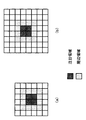
例えば、図3に示すように、注目領域が2×2サイズ、前記注目領域を含む周辺領域が4×4サイズの場合、設定されるブロックサイズは2倍拡大の場合は図3(a)に示す6×6サイズブロック、4倍拡大の場合は図3(b)に示す8×8サイズブロックが切り出される。
【0031】
次いで、ステップS21において、エッジ方向推定部12は、切り出された画像ブロック中の注目領域および前記注目領域を含む周辺領域中の参照領域のエッジ方向を計算し、得られた複数のエッジ方向から注目領域のエッジ方向θを推定する。
【0032】
次に、ステップS22において、エッジパターン選択部13は、エッジ方向推定部12で推定されたエッジ方向θおよび注目領域の画素分布パターンを用いて第1および第2エッジパターンを選択する。ここで第1および第2エッジパターンは、後述するエッジ方向および画素分布パターン毎に予め用意されており、図1中には図示しない記憶部などに例えばテーブル情報として記憶されている。
【0033】
続いて、ステップS23において、画像強調部12は、拡大率の応じたサイズおよび要素値をもつカーネルを用いて、前記画像ブロック設定部10で切り出された画像ブロック中の前記注目領域およびその周辺領域の画像データを強調する。
【0034】
次に、ステップS24において、拡大画像ブロック生成部14は、エッジ方向推定部12で推定された前記注目領域のエッジ方向θと、エッジパターン選択部13で選択された前記エッジパターンおよび画像強調部12において強調された前記注目領域および周辺領域の画素値を用いて、前記注目領域に対する拡大画像ブロックを生成する。
【0035】
その後、ステップS25において、画像ブロック配置部15は、拡大画像ブロック生成部14で生成された前記注目領域に対する拡大画像ブロックを後述する所定の方法で順次配置し、配置を終えた画像ブロックを画像データ格納部16に格納する。
【0036】
そして、ステップS26において、入力画像データに対して出力すべき拡大画像データが生成完了したかを判断し、完了していない場合は、ステップS20に処理を戻し、次の画像ブロックを切り出し上述の処理を繰り返す。完了した場合は、拡大画像データを出力して拡大処理を終了する。
【0037】
以上、本発明の実施形態における画像処理装置の概要および動作について記述した。次に、この画像処理装置の主要部であるエッジ方向推定部11、画像強調部12、エッジパターン選択部13および拡大画像ブロック生成部14および画像ブロック配置部15の詳細について説明する。
【0038】
先述の図3に示したように、注目領域2×2サイズブロック、前記注目領域を含む周辺領域4×4サイズブロックの場合を例にとり、本実施形態のエッジ方向推定部11におけるエッジ方向推定の詳細を述べる。
【0039】
図4(a)は注目領域および周辺領域の一例を示す図である。図4中において、注目領域は枠で囲まれた画素{a、b、c、d}={15、177、86、203}であり、各数字は各々の画素値を示すものとする。エッジ方向推定部11におけるエッジ方向推定処理の流れについて、図5に示すフローチャートを用いて説明する。
【0040】
先ず、ステップS50において、図4中の太線枠で囲まれた注目ブロックのエッジ方向θを以下の式(1)で計算する。また、後述するステップS55における注目領域のエッジ方向推定に用いるエッジ角度の参照数をカウントするための変数である角度参照数を1にセットする。
【0041】
gx = (a + c ≡ b ≡ d)/2
gy = (a + b ≡ c ≡ d)/2
θ = arctan(gy/gx) …(1)
【0042】
例えば、具体的に図4(a)に示すような注目領域{15、177、86、203})の場合、gx、gyはそれぞれ式(1)よりgx = -139.5、gy = -97となり、図4(a)に示す注目領域におけるエッジ方向θはθ=-145.2°となる。さらに図4(b)に示すように、得られたエッジ方向θを22.5°(8方向)で正規化した場合は、上記θ==-145.2°の場合は方向2となる。
【0043】
次に、ステップS51において、ステップS50で計算された注目領域のエッジ方向θに応じて、図4(a)に示した周辺領域中からエッジ方向推定に用いる参照領域を選択する。
【0044】
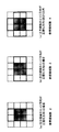
図6に、注目領域のエッジ方向による参照領域選択の一例を示す。本注目領域の場合は、正規化されたエッジ方向が方向2であるので、図6(c)に示した4つの参照領域(注目領域を含む上下左右2×2の4つの領域)が選択される。なお、参照領域の選択は図6に示したものに限定されるわけではなく、たとえば図6(c)の場合などは、参照領域数を8(注目領域を含む上下左右および斜め2×2の8つの領域)としたものを用いてもよい。
【0045】
次に、ステップS52において、ステップS51で選択された参照領域に対して、ステップS50と同様に式(1)に従って、エッジ方向θを計算する。
【0046】
その後、ステップS53において、ステップS52で計算された選択参照領域のエッジ方向と、ステップS50で計算された注目領域のエッジ方向とをそれぞれ比較する。
【0047】
両エッジ方向の差が予め設定されている閾値Thよりも小さい場合には、ステップS54において角度参照数を1増やし(ステップS54)、ステップS55に処理を移す。両エッジ方向の差が予め設定されている閾値Thよりも大きい場合には、エッジ方向推定には適さない参照領域と判断し、そのままステップS55に処理を移す。
【0048】
次に、ステップS55において、全ての選択参照領域のエッジ方向計算が終了したかどうか判断する。終了していればステップS56に処理を移し、まだ終了していない参照領域がある場合には、ステップS52からステップS54の処理を繰り返す。
【0049】
そして、ステップS56において、注目領域のエッジ方向と、ステップS53においてエッジ方向推定に適したと判断された参照領域のエッジ方向との総和を計算し、前記エッジ方向の総和を角度参照数で割った平均エッジ方向を注目領域の推定エッジ方向とする。
【0050】
このように、注目領域のエッジ方向として、注目領域のみで推定したエッジ方向から導かれる参照領域のエッジ方向も考慮して注目領域のエッジ方向を推定することによって、簡単な計算のみで精度の高いエッジ方向検出を行うことができるようになる。
【0051】
なお、上記に示したエッジ方向推定部11では、入力画像データがグレースケール画像である場合について説明を行っているが、勿論これに限定されるわけではない。例として図7にRGB色空間カラー画像の場合におけるエッジ方向推定処理の流れについて、フローチャートを用いて説明する。
【0052】
先ず、ステップS70において、注目領域におけるRGB各色空間ブロックそれぞれについて、上記式(1)および下記式(2)を用いてエッジ強度Gを計算する。
G = gx*gx + gy*gy …(2)
【0053】
次に、ステップS71において、式(2)で計算されたRGB各色空間ブロックの各々のエッジ強度に対して、最大のエッジ強度である色空間ブロックを選択する。
【0054】
次いで、ステップS72において、ステップS71で選択された色空間ブロックで、図5に示したエッジ方向推定処理であるステップS50からステップS56までの処理を行う。
【0055】
その後、ステップS73において、最大エッジ強度の色空間ブロックで推定された推定エッジ方向を他の色空間ブロックにおける推定エッジ方向とし、後述するエッジパターン選択部13および拡大画像ブロック生成部14に置ける処理を各色空間ブロックに対して行う。
【0056】
上述したステップS70からステップS73の処理を行うことで、カラー画像における拡大画像データのエッジ部の色ずれなど画質低下原因を抑えることが可能となる。
【0057】
なお、本実施形態では注目領域および参照領域における式(1)を用いたエッジ方向計算後の正規化を8方向として説明を行ってきたが、勿論これに限定されるわけではなく、さらに精度の高いエッジ方向が必要であれば12方向(15.0°)、16方向(12.25°)などに正規化しても良い。
【0058】
次に、エッジパターン選択部13の動作の詳細について説明する。エッジパターン選択部13では、例えば図9に示すようなエッジパターンテーブルを用いて、エッジ方向推定部11で推定された注目領域のエッジ方向に相当する第1エッジパターンを選択し、選択された第1エッジパターンに対応する第2エッジパターンを決定する。
【0059】
具体的に図4(a)に示す枠で囲まれた注目領域およびその周辺領域の場合について説明する。図4(a)に示した前記注目領域に対する推定エッジ方向は、上述のエッジ方向推定部11の各処理ステップにより、図8に示すように方向1と推定される(注目領域および4つの参照領域のエッジ方向の総和(-738.04)/角度参照数(5) = -147.6、正規化エッジ方向1)。
【0060】
推定された注目領域のエッジ方向(方向1)に従い、図9に示すエッジパターンテーブル内から注目領域のエッジパターンに相当するパターン候補が選択される。この場合、方向1の第1エッジパターンであるパターン0からパターン3の4つのパターンが、図4(a)に示す注目領域に対する第1エッジパターンの候補となる。
【0061】
次に、エッジパターン選択部13では、以下に説明するように、パターン0からパターン3のいずれか1つを注目領域に対する第1エッジパターンとして選択する。
【0062】
図10は、図4(a)に示した注目領域の場合について、4つのエッジパターン候補の中から1つのエッジパターンを選択する方法を具体的に説明した図である。まず、第1エッジパターン候補を図10(b)に示すようにビットパターン化する。(白部分を0、それ以外を1)。ただし、図9に示すエッジパターンテーブルを予めビットテーブル化して図1中に図示しない記憶部などに記憶しておいても良く、その場合は本処理は省略できる。
【0063】
次に、下記式(3)に従い、注目領域中の平均画素値(図4(a)の場合では120.25)を計算し、注目領域各々の画素値から平均値を引き、その符号を以って注目領域の画素値パターンとする(図10(c))。さらに画素値パターンをビットパターン化する(図10(d))。
【0064】
Mean = (a + b + c + d)/4
a_sign = a ≡ Mean
b_sign = b ≡ Mean
c_sign = c ≡ Mean
d_sign = d ≡ Mean …(3)
【0065】
次に、図10(b)の各エッジパターン候補のビットパターンと、図10(d)の注目領域のビットパターンにおいてパターンマッチングを行い、注目領域に対する第1エッジパターンを1つ選択する。この場合はパターン2が注目領域に対する第1エッジパターンとして選択される。
【0066】
最後に、第1エッジパターンが選択されると、それに1対1に対応するように予め用意された第2エッジパターンが決定する。この場合は図11に示す第2エッジパターンが選ばれる。第2エッジパターンは、後述する拡大画像ブロック生成部14における注目領域に対する拡大画像ブロック生成の際に使用される。
【0067】
なお、第1および第2エッジパターンは図9に示したものに限定されるわけではなく、例えば、入力画像データの種類に応じて図9とは異なったエッジパターンを用いてもよく、また各角度における第1および第2エッジパターン候補数を増減させてもよい。
【0068】
次に、画像強調部12について詳細に説明する。画像強調部12では、図1における拡大処理部1における拡大処理の拡大倍率に応じたサイズおよび要素のカーネルを用いて、先述の図3に示したような画像ブロック設定部10で切り出された画像ブロック中の注目領域およびその周辺領域の画像データのコントラストを強調する。
【0069】
図12に画像強調部12で用いる強調カーネルの具体的な一例を示す。また、図13は図12(a)に示したカーネル0を用いて画素Pを強調する様子を示した図である。この場合、画素Pの画素値P’は次の式(4)に従って計算される。
【0070】
注目画素値P’ = 1.60*P‐0.15*(a + b + c + d) (4)
a、b、c、d、Pはそれぞれ図13に示した位置の画素値である。
【0071】
図14に入力画像データを8倍拡大する場合、図12に示した各々の強調カーネルによるコントラスト強調の一例を示す。先ず、入力画像データを2倍拡大する場合に、図12(a)に示すカーネル0を用いて入力画像データのコントラスト強調を行う。
【0072】
次に、2倍拡大された画像データを2倍拡大する場合に、2倍拡大画像データに対して図12(b)に示すカーネル1を用いてコントラスト強調を行い、同様に8倍拡大する場合に、4倍拡大画像データに対して図12(c)に示すカーネル2を用いてコントラスト強調を行う。
【0073】
なお、コントラスト強調を施すカーネルは図12に示したものに限定されるわけではなく、入力画像データの種類およびサイズなどにより、カーネルの要素および要素間距離が図12と異なったカーネルを用いても勿論よい。
【0074】
次に、拡大画像ブロック生成部14について説明する。拡大画像ブロック生成部14では、エッジパターン選択部13で得られた前記第2エッジパターンと、画像強調部12においてコントラスト強調された画素値を用いて、注目領域に対する拡大画像ブロックを生成する。
【0075】
拡大画像ブロック生成部14における拡大画像ブロック生成処理の流れの一例について、図15に示すフローチャートを用いて説明する。先ず、ステップS150において、図16に示すように画像強調部12においてコントラスト強調された注目領域およびエッジパターン選択部13で選択された第2エッジパターンを用いて、まず3×3拡大画像ブロックを生成する。3×3拡大画像ブロックの各画素値は、図16中に示される式で計算される。この画素値計算式は第2エッジパターンによって決まっており、例えば図17中に他の第2エッジパターンにおける画素値計算式の具体的な例を示す。
【0076】
次に、ステップS151において、エッジ方向推定部11で推定された注目領域の推定エッジ方向を判断し、推定エッジ方向が方向1〜方向3および方向5〜方向7の場合はステップS152に、推定エッジ方向が方向0および方向4の場合はステップS153に処理を移す。
【0077】
ステップS152では、注目領域の推定エッジ方向が方向1〜方向3および方向5〜方向7の場合に、ステップS150で生成された3×3拡大画像ブロックから4×4拡大画像ブロックを生成する。
【0078】
先ず、図18に示すように、3×3拡大画像ブロックおよび画像強調部12においてコントラスト強調された周辺領域中の参照画素(r0からr5)を用いて、3×4拡大画像ブロックを生成する。3×4拡大画像ブロックの各画素値は図18に示す計算式により決定される。また周辺領域中の前記参照画素(r0からr5)は、注目領域における推定エッジ方向に従い選択される。
【0079】
図19に推定エッジ方向による選択される参照画素の具体的な一例を示す。なお、参照画素の選択は図19に示すように2パターンの選択例に限定されるわけではなく、推定エッジ方向に従い、より多くの参照画素選択パターンを用意してもよい。
【0080】
次に、図20に示すように、3×4拡大画像ブロックおよび画像強調部12においてコントラスト強調された周辺領域中の参照画素(r0からr7)を用いて、4×4拡大画像ブロックを生成する。4×4拡大画像ブロックの各画素値は図20内に示される計算式により決定される。
【0081】
なお、上記で説明したステップS152における4×4拡大画像ブロック生成において、3×3ブロック→3×4ブロック→4×4ブロック生成の処理の流れを示したが、勿論3×3ブロック→4×3ブロック→4×4ブロックの処理の流れでもよく、勿論この場合の参照画素選択は便宜変更される。
【0082】
ステップS153では、注目領域の推定エッジ方向が方向0および方向4の場合に、ステップS150で生成された3×3拡大画像ブロックから4×4拡大画像ブロックを生成する。
【0083】
図21にステップS153における4×4拡大画像ブロック生成処理の概要を示す。まず、画像強調部12においてコントラスト強調された注目領域および周辺領域ブロック(4×4ブロック)を1.25倍拡大する。この場合の拡大手法は線形拡大法であっても投影拡大法であってもよい。
【0084】
次に、拡大された5×5ブロックの中心部分(3×3ブロック)を、ステップS150で生成した3×3拡大画像ブロックで置き換え、さらに置き換えた5×5ブロックを1.2倍拡大する。この場合の拡大手法も線形拡大法であっても投影拡大法であってもよい。
【0085】
最後に、拡大された6×6ブロックの中心部分(4×4ブロック)を、注目領域に対する4×4拡大画像ブロックとして抜き出す。以上、ステップS150からステップS153の処理を行うことにより、例えば図22に示すような、注目領域に対する拡大画像ブロックが生成される。
【0086】
次に、画像ブロック配置部15について説明する。画像ブロック配置部15では、拡大画像ブロック生成部14で生成された注目領域に対する拡大画像ブロックを所定の方法により順次配置する。
【0087】
図23に、拡大画像ブロック生成部14で生成された4×4拡大画像ブロックを配置する具体的な一例を示す。図23に示す例では、順次生成された拡大画像ブロック0および拡大画像ブロック1をオーバーラップさせるように配置している。オーバーラップする画素は各々前画素値との平均をよるようにして配置する。
【0088】
このような本実施形態の画像処理装置および画像処理方法によって、画像の拡大処理を行うにあたり、簡単なパターンマッチングのみでエッジ方向に対応したエッジ形状パターンを選択できるとともに、選択されたエッジ形状パターンに基づくエッジ方向を考慮した画素値を用いて拡大画像を生成することから、ボケやジャギーの発生を抑制した拡大画像を少ない処理負荷によって実現できるようになる。
【0089】
なお、上記説明した画像処理方法は、画像処理プログラムとしてパーソナルコンピュータ等で実行されたり、インターネット等の通信回線を介して配信されたり、コンピュータ読取可能な記録媒体(例えば、CD−ROM)に記録される態様であってもよい。
【0090】
また、このような画像処理プログラムは、デジタルスチルカメラ、デジタルビデオカメラ、携帯電話、PDA(携帯端末)等のデジタル画像を取り扱う機器において取り込み画像をデジタル的に拡大する場合にも適用可能である。
【0091】
【発明の効果】
以上説明したように本発明では、画像の拡大処理において、正確なエッジ方向を検出し、そのエッジ方向に応じた画素値から拡大画像を生成することから、ボケやジャギーの画質欠陥を抑制した高画質な拡大処理を小さな処理負荷で高速に実現することが可能となる。
【図面の簡単な説明】
【図1】 本発明の実施の形態の基本構成を示すブロック図である。
【図2】 本発明の実施の形態の処理の流れを示すフローチャートである。
【図3】 画像ブロック設定部で切り出される画像ブロックおよび注目領域、周辺領域の例を示す図である。
【図4】 注目領域および周辺領域の具体的な一例と注目領域のエッジ方向を説明する図である。
【図5】 エッジ方向推定部におけるエッジ方向推定処理の流れを示すフローチャートである。
【図6】 エッジ方向推定に用いる参照領域の例を示す図である。
【図7】 エッジ方向推定部における、RGB色空間カラー画像に対するエッジ方向推定処理の流れを示すフローチャートである。
【図8】 図4の注目領域における推定エッジ方向を示す図である。
【図9】 エッジパターンテーブルの具体的な一例を示す図である。
【図10】 図4の注目領域に対して、第1エッジパターンを選択する方法を具体的に説明した図である。
【図11】 図4の注目領域における第2エッジパターンを示す図である。
【図12】 画像強調部で用いる強調カーネルの具体的な例を示す図である。
【図13】 図12(a)の強調カーネルで画素Pを強調する例を示す図である。
【図14】 入力画像データを8倍拡大する場合の、強調カーネルによるコントラスト強調を説明する図である。
【図15】 拡大画像ブロック生成部14における、拡大画像ブロック生成処理の流れを示すフローチャートである。
【図16】 3×3拡大画像ブロック生成の具体的な一例を示す図である。
【図17】 図16の第2エッジパターンと異なる第2エッジパターンの場合の、3×3拡大画像ブロック生成の例を示す図である。
【図18】 3×4拡大画像ブロック生成の具体的な一例を示す図である。
【図19】 推定エッジ方向による参照画素の選択を説明する図である。
【図20】 4×4拡大画像ブロック生成の具体的な一例を示す図である。
【図21】 推定エッジ方向が方向0および方向4の場合における、4×4拡大画像ブロック生成の例を示す図である。
【図22】 注目領域に対する拡大画像ブロックを示す図である。
【図23】 画像ブロック配置部における、4×4拡大画像ブロック配置の具体的な一例を示す図である。
【符号の説明】
1…拡大処理部、10…画像ブロック設定部、11…エッジ方向推定部、12…画像強調部、13…エッジパターン選択部、14…拡大画像ブロック生成部、15…画像ブロック配置部、16…画像データ格納部[0001]
BACKGROUND OF THE INVENTION
The present invention is intended for enlargement processing of an image expressed in multiple gradations, and in particular, image processing for performing enlargement processing with high image quality while suppressing occurrence of image quality defects such as blurring and jaggy on an input image. The present invention relates to an apparatus, an image processing method, an image processing program, and a computer-readable recording medium on which the image processing program is recorded.
[0002]
[Prior art]
The image enlargement process is one of the basic processes for image editing, filing, display, and printing systems. In recent years, it has been possible to display images on the Internet homepage and display them at display resolutions such as digital video. Due to the widespread use of image data as the main purpose, high-quality enlargement processing is becoming increasingly important in order to obtain high-quality output results when printing these low-resolution images with a high-resolution printer. .
[0003]
As existing methods for enlarging an image expressed in multiple gradations (hereinafter referred to as a multi-valued image), there are a nearest neighbor method, a linear interpolation method, a cubic convolution method, and the like.
[0004]
The nearest neighbor method uses the pixel value of the pixel with the closest distance when the pixel is inversely mapped on the original image as each pixel value after enlargement. Since one pixel of the original image is directly enlarged into a rectangular shape, the degree of image quality degradation is large, such as jaggy in the shaded area or a mosaic image when the magnification is large.
[0005]
In the linear interpolation method, it is assumed that pixel values between pixels change linearly, and pixel values of four pixels in the vicinity of a point obtained by inversely mapping the enlarged pixel are linearly interpolated to obtain a pixel value. Although it is heavier than the nearest neighbor method, the amount of computation is relatively small, and jaggies are not likely to occur. On the other hand, there is a drawback that the entire image becomes blurred, centering on the edge portion that does not apply to the assumption that it changes linearly.
[0006]
The cubic convolution method defines an interpolation function that approximates a sinc function (sin (x) / x) based on the sampling theorem, and 16 pixels in the vicinity of a point obtained by inversely mapping the enlarged pixel (X and Y directions) This is a method for obtaining an enlarged pixel value by convolution of each of the four pixels) and the approximate interpolation function. This method has a relatively good image quality compared to the above two methods, but has a large reference range and a large amount of calculation, and has a characteristic of high frequency emphasis, so that light jaggy occurs at the edge portion and noise components are emphasized. There are drawbacks such as
[0007]
As an attempt to solve these problems, for example, Japanese Patent Application Laid-Open No. 7-182503, Japanese Patent Application Laid-Open No. 2000-228723, Japanese Patent Application Laid-Open No. 2000-253238, “High-quality image enlargement reproduction using an adaptive two-dimensional sampling function” "Structure" (The Institute of Image Electronics Engineers of Japan, Vol. 28, No. 5, PP620-626) has been proposed.
[0008]
[Problems to be solved by the invention]
Japanese Patent Application Laid-Open No. 7-182503 detects the maximum value and the minimum value from the pixels in the N × M region (for example, 3 × 3) around the pixel of interest, calculates the contrast and the intermediate value, and calculates the maximum value based on this contrast. An average value of any one of the minimum values and other values is derived as a representative value. Next, the target pixel is linearly interpolated into N × M pixels, binarized using the previously calculated intermediate value as a threshold, and the two representative values are arranged according to the binarization result. When the contrast is low, the pixel value of the linear interpolation process is used as it is to finally obtain an enlarged image.
[0009]
As a result, it is stated that jaggies do not occur and it is possible to perform good conversion without interpolation blur even in a natural image, but the edge part is judged only by contrast, and it is difficult to reproduce the edge direction. There is. Further, since the N × M region is composed of only two values, there is a problem that block-like distortion occurs in the edge portion.
[0010]
Japanese Patent Laid-Open No. 2000-228723 obtains an original image by binarizing and determining the direction of the diagonal component included in the original image from the binary image to coincide with a prepared two-dimensional pattern (matrix data). Then, interpolation processing is performed along the obtained oblique direction. In addition, linear interpolation processing is performed for the other portions.
[0011]
However, since the direction of the diagonal component is determined after binarizing the original image with a predetermined threshold, it is effective for edges with a large density difference, but for reproducing edges with a small density difference. There's a problem.
[0012]
Japanese Patent Laid-Open No. 2000-253238 enlarges an original image by linear interpolation processing, and in parallel with it, binarizes each surrounding N × M region including the target pixel in the original image, and detects a diagonal line set in advance. If the pixel of interest belongs to the edge region (matches the oblique line detection pattern), the direction information is mapped to the pixel of interest. Further, this direction information is mapped to the enlarged image previously enlarged by the linear interpolation process, and the smoothing filter is applied along the direction of the mapped direction information, thereby performing the enlargement process suppressing the occurrence of jaggy.
[0013]
However, the method of Japanese Patent Laid-Open No. 2000-253238 is a flow of enlargement of an original image, pattern matching, enlargement of direction information, and direction-dependent smoothing filter processing for an enlarged image, and the processing load becomes very large as the image size increases. There is a problem of becoming larger.
[0014]
In addition, the above "high-quality image enlargement reconstruction using an adaptive two-dimensional sampling function" (Image Electronics Society of Japan Vol. 28, No. 5, PP 620 to 626) is an infinite series of sinc functions in the cubic convolution method. The problem is that there are many discontinuous points in the image while there are errors due to the use of approximate functions that are finite and truncated, and the sampling theorem is for continuous and differentiable signals. An enlarged image with less blur and jaggy by using a function with discontinuity that is different from the sinc function and having locality as the interpolation function, and further detecting the edge direction globally and transforming the interpolation function in that direction. Is what you get.
[0015]
However, the function used in this method has a problem that the amount of calculation is large due to detection of a global edge direction or the like because the convolution matrix size is 4n with respect to the magnification n although it is local.
[0016]
The present invention has been made in consideration of the above-described problems of the prior art, and an image processing apparatus, an image processing method, and an image processing apparatus that can obtain an enlarged image with less blur and jaggy at a high speed with a small processing load. It is an object of the present invention to realize a computer-readable recording medium in which a processing program and an image processing program are recorded.
[0017]
[Means for Solving the Problems]
In order to achieve the above object, the present invention estimates edge direction information for a first image region including a target pixel, and an edge shape corresponding to the first image region corresponding to the estimated predetermined edge direction. A pattern is selected based on the edge direction information and the pixel value in the image area including the target pixel, and the pixel value in the first image area including the target pixel is emphasized. Then, an enlarged image area is generated using the selected edge shape pattern and the emphasized pixel value of the first image area, and the enlarged image area is arranged by a predetermined method. Here, the edge shape pattern to be selected includes a first edge shape pattern corresponding to the first image region including the target pixel, and The first edge shape pattern corresponds to the edge direction, Second edge shape patterns of different sizes When It is what has.
[0018]
In the present invention, the edge direction information is estimated for the first image area including the target pixel, and the edge shape pattern corresponding to the first image area corresponding to the estimated predetermined edge direction is determined as the edge direction. Since the selection is performed based on the pixel values in the image area including the information and the target pixel, the edge shape pattern corresponding to the edge direction can be determined only by simple pattern matching. Further, the pixel value of the first image region including the target pixel is emphasized, an enlarged image region is generated using the selected edge shape pattern and the emphasized pixel value in the first image region, and the enlarged image By arranging the regions by a predetermined method, an enlarged image in consideration of the edge direction can be generated, and an enlarged image with less blur and jaggy can be obtained at a high speed with a small processing load.
[0019]
DETAILED DESCRIPTION OF THE INVENTION
Hereinafter, embodiments of the present invention will be described with reference to the drawings. FIG. 1 is a block diagram illustrating a processing unit that performs an enlargement process of an image processing apparatus according to an embodiment of the present invention. In the figure, the
[0020]
In FIG. 1, the image data is described in an image format (for example, BMP, TIFF, PNG) that can be processed by the image processing apparatus, and an application for processing creation and editing in a personal computer or a digital camera (not shown). It is generated from image data created by a program.
[0021]
The image
[0022]
The image
[0023]
The edge direction estimation unit 11 calculates an edge direction in a region of interest in the image block sequentially cut out by the image
[0024]
The
[0025]
The edge
[0026]
The enlarged image
[0027]
The image
[0028]
Next, an outline of the flow of enlargement processing in the embodiment of the present invention will be described using the flowchart shown in FIG. In the following description, reference numerals not shown in FIG. 2 refer to FIG.
[0029]
First, in step S20, the input image data input from an input device (not shown) and stored in the image
[0030]
For example, as shown in FIG. 3, when the attention area is 2 × 2 size and the peripheral area including the attention area is 4 × 4 size, the set block size is doubled as shown in FIG. In the case of the 6 × 6 size block shown and 4 × enlargement, the 8 × 8 size block shown in FIG. 3B is cut out.
[0031]
Next, in step S21, the edge
[0032]
Next, in step S22, the edge
[0033]
Subsequently, in step S23, the
[0034]
Next, in step S24, the enlarged image
[0035]
Thereafter, in step S25, the image
[0036]
In step S26, it is determined whether the enlarged image data to be output with respect to the input image data has been generated. If not, the process returns to step S20, and the next image block is cut out and the processing described above is performed. repeat. If completed, the enlarged image data is output and the enlargement process ends.
[0037]
The outline and operation of the image processing apparatus according to the embodiment of the present invention have been described above. Next, details of the edge direction estimation unit 11, the
[0038]
As shown in FIG. 3, the edge direction estimation unit 11 of the present embodiment performs edge direction estimation, taking as an example the case of an
[0039]
FIG. 4A shows an example of the attention area and the peripheral area. In FIG. 4, the region of interest is a pixel {a, b, c, d} = {15, 177, 86, 203} surrounded by a frame, and each number represents each pixel value. The flow of edge direction estimation processing in the edge direction estimation unit 11 will be described with reference to the flowchart shown in FIG.
[0040]
First, in step S50, the edge direction θ of the block of interest surrounded by the thick line frame in FIG. 4 is calculated by the following equation (1). In addition, an angle reference number that is a variable for counting the reference number of the edge angle used for estimating the edge direction of the attention area in step S55 described later is set to 1.
[0041]
gx = (a + c ≡ b ≡ d) / 2
gy = (a + b ≡ c ≡ d) / 2
θ = arctan (gy / gx) (1)
[0042]
For example, in the case of a region of interest {15, 177, 86, 203}) as specifically shown in FIG. 4A, gx and gy are gx = −139.5 and gy = −97, respectively, from the equation (1), The edge direction θ in the region of interest shown in FIG. 4A is θ = −145.2 °. Further, as shown in FIG. 4B, when the obtained edge direction θ is normalized by 22.5 ° (8 directions), the
[0043]
Next, in step S51, a reference area used for edge direction estimation is selected from the peripheral areas shown in FIG. 4A in accordance with the edge direction θ of the attention area calculated in step S50.
[0044]
FIG. 6 shows an example of reference area selection based on the edge direction of the attention area. In the case of this attention area, since the normalized edge direction is
[0045]
Next, in step S52, the edge direction θ is calculated for the reference region selected in step S51 according to the equation (1) as in step S50.
[0046]
Thereafter, in step S53, the edge direction of the selected reference area calculated in step S52 is compared with the edge direction of the attention area calculated in step S50.
[0047]
If the difference between the two edge directions is smaller than the preset threshold Th, the number of angle references is increased by 1 in step S54 (step S54), and the process proceeds to step S55. If the difference between the two edge directions is larger than a preset threshold value Th, it is determined that the reference area is not suitable for the edge direction estimation, and the process proceeds to step S55.
[0048]
Next, in step S55, it is determined whether or not the edge direction calculation of all selected reference areas has been completed. If completed, the process proceeds to step S56. If there is a reference area that has not been completed, the process from step S52 to step S54 is repeated.
[0049]
Then, in step S56, the sum of the edge direction of the region of interest and the edge direction of the reference region determined to be suitable for the edge direction estimation in step S53 is calculated, and the average obtained by dividing the sum of the edge directions by the angle reference number Let the edge direction be the estimated edge direction of the region of interest.
[0050]
In this way, the edge direction of the attention area is estimated in consideration of the edge direction of the reference area derived from the edge direction estimated only by the attention area as the edge direction of the attention area, so that high accuracy can be obtained by simple calculation alone. Edge direction detection can be performed.
[0051]
Note that although the edge direction estimation unit 11 described above has described the case where the input image data is a grayscale image, the present invention is not limited to this. As an example, the flow of edge direction estimation processing in the case of an RGB color space color image will be described with reference to a flowchart in FIG.
[0052]
First, in step S70, the edge strength G is calculated for each RGB color space block in the region of interest using the above equation (1) and the following equation (2).
G = gx * gx + gy * gy (2)
[0053]
Next, in step S71, the color space block having the maximum edge strength is selected for each edge strength of each RGB color space block calculated by the equation (2).
[0054]
Next, in step S72, the process from step S50 to step S56, which is the edge direction estimation process shown in FIG. 5, is performed on the color space block selected in step S71.
[0055]
After that, in step S73, the estimated edge direction estimated in the color space block with the maximum edge strength is set as the estimated edge direction in the other color space block, and processing that can be placed in the edge
[0056]
By performing the processing from step S70 to step S73 described above, it is possible to suppress the cause of image quality degradation such as a color shift at the edge portion of the enlarged image data in the color image.
[0057]
In the present embodiment, the normalization after the edge direction calculation using the expression (1) in the attention area and the reference area has been described as eight directions, but of course, the present invention is not limited to this. If a high edge direction is required, it may be normalized to 12 directions (15.0 °), 16 directions (12.25 °), and the like.
[0058]
Next, details of the operation of the edge
[0059]
Specifically, the case of the attention area surrounded by a frame shown in FIG. The estimated edge direction for the region of interest shown in FIG. 4A is estimated as
[0060]
In accordance with the estimated edge direction (direction 1) of the attention area, pattern candidates corresponding to the edge pattern of the attention area are selected from the edge pattern table shown in FIG. In this case, four patterns from pattern 0 to pattern 3, which are the first edge patterns in
[0061]
Next, the edge
[0062]
FIG. 10 is a diagram specifically explaining a method of selecting one edge pattern from four edge pattern candidates in the case of the attention area shown in FIG. First, the first edge pattern candidate is formed into a bit pattern as shown in FIG. (White part is 0, otherwise 1). However, the edge pattern table shown in FIG. 9 may be converted into a bit table in advance and stored in a storage unit (not shown in FIG. 1). In this case, this process can be omitted.
[0063]
Next, the average pixel value in the attention area (120.25 in the case of FIG. 4A) is calculated according to the following formula (3), the average value is subtracted from the pixel values of each attention area, and the sign is used. A pixel value pattern of the region of interest is set (FIG. 10C). Further, the pixel value pattern is converted into a bit pattern (FIG. 10D).
[0064]
Mean = (a + b + c + d) / 4
a_sign = a ≡ Mean
b_sign = b ≡ Mean
c_sign = c ≡ Mean
d_sign = d ≡ Mean (3)
[0065]
Next, pattern matching is performed on the bit pattern of each edge pattern candidate in FIG. 10B and the bit pattern of the attention area in FIG. 10D to select one first edge pattern for the attention area. In this case,
[0066]
Finally, when the first edge pattern is selected, the second edge pattern prepared in advance so as to correspond to the first edge pattern is determined. In this case, the second edge pattern shown in FIG. 11 is selected. The second edge pattern is used when generating an enlarged image block for the attention area in the enlarged image
[0067]
The first and second edge patterns are not limited to those shown in FIG. 9. For example, an edge pattern different from that shown in FIG. 9 may be used depending on the type of input image data. The number of first and second edge pattern candidates in the angle may be increased or decreased.
[0068]
Next, the
[0069]
FIG. 12 shows a specific example of the enhancement kernel used in the
[0070]
Pixel value of interest P '= 1.60 * P-0.15 * (a + b + c + d) (4)
a, b, c, d, and P are pixel values at the positions shown in FIG.
[0071]
FIG. 14 shows an example of contrast enhancement by each enhancement kernel shown in FIG. 12 when the input image data is enlarged eight times. First, when the input image data is enlarged twice, the contrast enhancement of the input image data is performed using the kernel 0 shown in FIG.
[0072]
Next, when the image data enlarged twice is enlarged twice, the contrast enhancement is performed on the twice enlarged image data using the
[0073]
Note that the kernel for performing contrast enhancement is not limited to that shown in FIG. 12, and a kernel having different kernel elements and inter-element distances as shown in FIG. 12 may be used depending on the type and size of input image data. Of course.
[0074]
Next, the enlarged image
[0075]
An example of the flow of enlarged image block generation processing in the enlarged image
[0076]
Next, in step S151, the estimated edge direction of the attention area estimated by the edge direction estimation unit 11 is determined. If the estimated edge directions are
[0077]
In step S152, when the estimated edge directions of the attention area are
[0078]
First, as shown in FIG. 18, a 3 × 4 enlarged image block is generated using the 3 × 3 enlarged image block and the reference pixels (r0 to r5) in the peripheral region in which the contrast enhancement is performed in the
[0079]
FIG. 19 shows a specific example of reference pixels selected by the estimated edge direction. Note that the selection of reference pixels is not limited to the selection example of two patterns as shown in FIG. 19, and more reference pixel selection patterns may be prepared according to the estimated edge direction.
[0080]
Next, as illustrated in FIG. 20, a 4 × 4 enlarged image block is generated using the 3 × 4 enlarged image block and the reference pixels (r0 to r7) in the peripheral region in which the contrast enhancement is performed in the
[0081]
In addition, in the 4 × 4 enlarged image block generation in step S152 described above, the flow of processing of 3 × 3 block → 3 × 4 block → 4 × 4 block generation is shown. Of course, 3 × 3 block → 4 × The processing flow from 3 blocks to 4 × 4 blocks may be used. Of course, the reference pixel selection in this case is changed for convenience.
[0082]
In step S153, when the estimated edge directions of the attention area are direction 0 and direction 4, a 4 × 4 enlarged image block is generated from the 3 × 3 enlarged image block generated in step S150.
[0083]
FIG. 21 shows an outline of the 4 × 4 enlarged image block generation processing in step S153. First, the attention area and the peripheral area block (4 × 4 blocks) whose contrast is enhanced in the
[0084]
Next, the central portion (3 × 3 block) of the enlarged 5 × 5 block is replaced with the 3 × 3 enlarged image block generated in step S150, and the replaced 5 × 5 block is enlarged by 1.2 times. The enlargement method in this case may be a linear enlargement method or a projection enlargement method.
[0085]
Finally, the center portion (4 × 4 block) of the enlarged 6 × 6 block is extracted as a 4 × 4 enlarged image block for the region of interest. As described above, by performing the processing from step S150 to step S153, an enlarged image block for the attention area as shown in FIG. 22, for example, is generated.
[0086]
Next, the image
[0087]
FIG. 23 shows a specific example of arranging 4 × 4 enlarged image blocks generated by the enlarged image
[0088]
With such an image processing apparatus and image processing method of the present embodiment, when performing image enlargement processing, an edge shape pattern corresponding to the edge direction can be selected only by simple pattern matching, and the selected edge shape pattern can be selected. Since the enlarged image is generated using the pixel value in consideration of the edge direction based on the enlarged image, an enlarged image in which the occurrence of blurring and jaggy is suppressed can be realized with a small processing load.
[0089]
The image processing method described above is executed as an image processing program by a personal computer or the like, distributed via a communication line such as the Internet, or recorded on a computer-readable recording medium (for example, a CD-ROM). It may be an embodiment.
[0090]
Such an image processing program can also be applied to a case where a captured image is digitally enlarged in a device that handles digital images, such as a digital still camera, a digital video camera, a mobile phone, and a PDA (mobile terminal).
[0091]
【The invention's effect】
As described above, according to the present invention, in the image enlargement process, an accurate edge direction is detected, and an enlarged image is generated from pixel values corresponding to the edge direction. An image quality enlargement process can be realized at high speed with a small processing load.
[Brief description of the drawings]
FIG. 1 is a block diagram showing a basic configuration of an embodiment of the present invention.
FIG. 2 is a flowchart showing a flow of processing according to the embodiment of the present invention.
FIG. 3 is a diagram illustrating an example of an image block cut out by an image block setting unit, a region of interest, and a peripheral region.
FIG. 4 is a diagram illustrating a specific example of a region of interest and a peripheral region, and edge directions of the region of interest.
FIG. 5 is a flowchart showing a flow of edge direction estimation processing in an edge direction estimation unit.
FIG. 6 is a diagram illustrating an example of a reference region used for edge direction estimation.
FIG. 7 is a flowchart showing a flow of edge direction estimation processing for an RGB color space color image in an edge direction estimation unit.
FIG. 8 is a diagram illustrating an estimated edge direction in the region of interest in FIG.
FIG. 9 is a diagram illustrating a specific example of an edge pattern table.
10 is a diagram specifically illustrating a method for selecting a first edge pattern for the region of interest in FIG. 4; FIG.
11 is a diagram showing a second edge pattern in the region of interest in FIG. 4. FIG.
FIG. 12 is a diagram illustrating a specific example of an enhancement kernel used in an image enhancement unit.
FIG. 13 is a diagram illustrating an example in which a pixel P is emphasized by the enhancement kernel of FIG.
FIG. 14 is a diagram for explaining contrast enhancement by an enhancement kernel when input image data is enlarged by 8 times;
FIG. 15 is a flowchart showing a flow of enlarged image block generation processing in the enlarged image block generation unit;
FIG. 16 is a diagram illustrating a specific example of 3 × 3 enlarged image block generation.
FIG. 17 is a diagram illustrating an example of 3 × 3 enlarged image block generation in the case of a second edge pattern different from the second edge pattern of FIG. 16;
FIG. 18 is a diagram illustrating a specific example of 3 × 4 enlarged image block generation.
FIG. 19 is a diagram illustrating selection of a reference pixel based on an estimated edge direction.
FIG. 20 is a diagram illustrating a specific example of 4 × 4 enlarged image block generation.
FIG. 21 is a diagram illustrating an example of 4 × 4 enlarged image block generation when the estimated edge directions are direction 0 and direction 4;
FIG. 22 is a diagram illustrating an enlarged image block for a region of interest.
FIG. 23 is a diagram illustrating a specific example of 4 × 4 enlarged image block arrangement in the image block arrangement unit.
[Explanation of symbols]
DESCRIPTION OF
Claims (19)
注目画素を含む第1の画像領域に対してエッジ方向情報を推定するエッジ方向推定手段と、
前記エッジ方向推定手段で推定した所定のエッジ方向に相当する前記第1の画像領域に対応したエッジ形状パターンを前記エッジ方向情報と前記注目画素を含む画像領域内の画素値とにより選択するエッジパターン選択手段と、
前記注目画素を含む第1の画像領域の画素値を強調する画像強調手段と、
前記エッジパターン選択手段で選択されたエッジ形状パターンと前記画像強調手段で強調された第1の画像領域の画素値とを用いて、拡大画像領域を生成する拡大画像領域生成手段と、
前記拡大画像領域生成手段で生成された拡大画像領域を所定の方法で配置する画像配置手段とを有しており、
前記エッジパターン選択手段のエッジ形状パターンには、前記注目画素を含む第1の画像領域に対応した第1のエッジ形状パターンと、その第1のエッジ形状パターンとエッジ方向が対応し、サイズの異なる第2のエッジ形状パターンとを有している
ことを特徴とする画像処理装置。In an image processing apparatus that performs image enlargement processing,
Edge direction estimation means for estimating edge direction information for the first image region including the pixel of interest;
An edge pattern for selecting an edge shape pattern corresponding to the first image area corresponding to the predetermined edge direction estimated by the edge direction estimating means based on the edge direction information and a pixel value in the image area including the target pixel A selection means;
Image enhancement means for enhancing the pixel value of the first image region including the target pixel;
An enlarged image region generating unit that generates an enlarged image region using the edge shape pattern selected by the edge pattern selecting unit and the pixel value of the first image region emphasized by the image enhancing unit;
Image arrangement means for arranging the enlarged image area generated by the enlarged image area generation means by a predetermined method,
The edge shape pattern of the edge pattern selection means corresponds to the first edge shape pattern corresponding to the first image region including the target pixel, and the first edge shape pattern and the edge direction are different in size. the image processing apparatus characterized by and a second edge shape pattern.
ことを特徴とする請求項1記載の画像処理装置。The edge direction estimation means calculates each edge angle based on a pixel value difference for each of the first image area including the target pixel and the surrounding image area, and calculates the edge angle from the calculated plurality of edge angles. The image processing apparatus according to claim 1, wherein edge direction information of the first image area including the target pixel is estimated.
ことを特徴とする請求項1記載の画像処理装置。The image processing apparatus according to claim 1, wherein the edge direction estimation unit is capable of selecting the image area used for edge direction information estimation of the first image area including the target pixel.
ことを特徴とする請求項1記載の画像処理装置。The image processing apparatus according to claim 1, wherein the edge direction information estimated by the edge direction estimation unit is normalized in a predetermined number of directions.
ことを特徴とする請求項1記載の画像処理装置。The image processing apparatus according to claim 1, wherein the edge direction estimating unit calculates edge direction information at the same time as estimating edge direction information of the first image region including the target pixel.
ことを特徴とする請求項1記載の画像処理装置。The edge direction estimation means selects one color space data from among the color space data according to the edge intensity information, and estimates the edge direction information from the selected color space data. Image processing apparatus.
ことを特徴とする請求項1記載の画像処理装置。The image processing apparatus according to claim 1, wherein the edge pattern selection unit has at least one edge shape pattern with respect to certain specific edge direction information.
ことを特徴とする請求項1記載の画像処理装置。The edge pattern selection means, when there are a plurality of edge shape patterns corresponding to the first image area including the pixel of interest with respect to the specific edge direction information, the first image including the pixel of interest The image processing apparatus according to claim 1, wherein each pixel in the region is converted into a binary pattern, and one edge shape pattern is selected by pattern matching with the edge shape pattern.
ことを特徴とする請求項1記載の画像処理装置。The image processing apparatus according to claim 1, wherein the first edge shape pattern and the second edge shape pattern have a one-to-one correspondence .
ことを特徴とする請求項1記載の画像処理装置。The image processing apparatus according to claim 1, wherein the image enhancement means includes a plurality of enhancement kernels having different kernel elements and distances between kernel elements, and each enhancement kernel is applied according to an enlargement ratio.
ことを特徴とする請求項1記載の画像処理装置。The image processing apparatus according to claim 1, wherein the enlarged image region generating unit includes a first enlarged image region generating unit and a second enlarged image region generating unit.
ことを特徴とする請求項11記載の画像処理装置。The first enlarged image region generation unit calculates the pixel value in the first image region emphasized by the image enhancement unit or the pixel value using two or more pixels for each pattern in the edge shape pattern. The image processing apparatus according to claim 11, wherein the first image area is enlarged using a value to generate a first enlarged image area.
ことを特徴とする請求項11記載の画像処理装置。The image processing apparatus according to claim 11, wherein the second enlarged image area generating unit enlarges the first enlarged image area by using different means according to the edge direction information estimated by the edge direction estimating unit.
ことを特徴とする請求項11記載の画像処理装置。One enlarging means in the second enlarged image area generating means uses a pixel value in the first enlarged image area and a pixel value around the first image area emphasized by the image emphasizing means. The image processing apparatus according to claim 11, wherein the second enlarged image area is generated by calculation.
ことを特徴とする請求項11記載の画像処理装置。The one enlargement unit in the second enlarged image region generation unit selects pixel values around the first image region according to the edge direction information estimated by the edge direction estimation unit. The image processing apparatus described.
ことを特徴とする請求項11記載の画像処理装置。Another enlargement unit in the second enlarged image region generation unit uses the value obtained by converting the pixel values around the first image region emphasized by the image enhancement unit by a predetermined calculation, to use the second enlarged image region. The image processing apparatus according to claim 11, wherein:
ことを特徴とする請求項1記載の画像処理装置。The image processing apparatus according to claim 1, wherein the image arrangement unit sequentially arranges the enlarged image areas that are sequentially generated so as to overlap each other.
ことを特徴とする請求項1記載の画像処理装置。 The edge pattern selection unit subtracts an average pixel value of the image area from each pixel value in the image area including the target pixel, generates a pixel value pattern according to the result, and generates the pixel value pattern and the first pattern value. The second edge shape pattern is selected based on the one edge shape pattern
The image processing apparatus according to claim 1 .
注目画素を含む第1の画像領域に対してエッジ方向情報を推定するステップと、
推定した所定のエッジ方向に相当する前記第1の画像領域に対応したエッジ形状パターンを前記エッジ方向情報と前記注目画素を含む画像領域内の画素値とにより選択し、前記注目画素を含む第1の画像領域の画素値を強調するステップと、
選択された前記エッジ形状パターンと前記第1の画像領域内の強調された画素値とを用いて拡大画像領域を生成し、前記拡大画像領域を所定の方法で配置するステップとを備える画像処理プログラムにおいて、
前記エッジ形状パターンの選択では、前記注目画素を含む第1の画像領域に対応した第1のエッジ形状パターンと、その第1のエッジ形状パターンとエッジ方向が対応し、サイズの異なる第2のエッジ形状パターンとを選択する
ことを特徴とする画像処理プログラム。In an image processing program that performs image enlargement processing,
Estimating edge direction information for a first image region including a pixel of interest;
An edge shape pattern corresponding to the first image area corresponding to the estimated predetermined edge direction is selected based on the edge direction information and a pixel value in the image area including the target pixel, and the first shape including the target pixel is selected. Enhancing the pixel values of the image area of
Generating an enlarged image area by using the selected the edge shape pattern and the enhanced pixel values of the first image region, the image processing program comprising the steps of placing the enlarged image region in a predetermined manner In
In the selection of the edge shape pattern, a first edge shape pattern corresponding to the first image region including the target pixel, and a second edge having a different size corresponding to the first edge shape pattern and the edge direction. image processing program and selects the shape pattern.
Priority Applications (5)
| Application Number | Priority Date | Filing Date | Title |
|---|---|---|---|
| JP2002076896A JP3915563B2 (en) | 2002-03-19 | 2002-03-19 | Image processing apparatus and image processing program |
| DE60321739T DE60321739D1 (en) | 2002-03-19 | 2003-02-10 | Edge-based enlargement and interpolation of images |
| EP03002641A EP1347410B1 (en) | 2002-03-19 | 2003-02-10 | Edge-based enlargement and interpolation of images |
| US10/360,874 US7149355B2 (en) | 2002-03-19 | 2003-02-10 | Image processing apparatus, image processing method, image processing program, and computer-readable record medium storing image processing program |
| CN031025625A CN1217526C (en) | 2002-03-19 | 2003-02-10 | Image processing device, image processing method, image processing program and its recording medium |
Applications Claiming Priority (1)
| Application Number | Priority Date | Filing Date | Title |
|---|---|---|---|
| JP2002076896A JP3915563B2 (en) | 2002-03-19 | 2002-03-19 | Image processing apparatus and image processing program |
Publications (2)
| Publication Number | Publication Date |
|---|---|
| JP2003274157A JP2003274157A (en) | 2003-09-26 |
| JP3915563B2 true JP3915563B2 (en) | 2007-05-16 |
Family
ID=27785230
Family Applications (1)
| Application Number | Title | Priority Date | Filing Date |
|---|---|---|---|
| JP2002076896A Expired - Fee Related JP3915563B2 (en) | 2002-03-19 | 2002-03-19 | Image processing apparatus and image processing program |
Country Status (5)
| Country | Link |
|---|---|
| US (1) | US7149355B2 (en) |
| EP (1) | EP1347410B1 (en) |
| JP (1) | JP3915563B2 (en) |
| CN (1) | CN1217526C (en) |
| DE (1) | DE60321739D1 (en) |
Cited By (1)
| Publication number | Priority date | Publication date | Assignee | Title |
|---|---|---|---|---|
| US7885486B2 (en) | 2006-07-31 | 2011-02-08 | Fuji Xerox Co., Ltd. | Image processing system, method for processing image and computer readable medium |
Families Citing this family (34)
| Publication number | Priority date | Publication date | Assignee | Title |
|---|---|---|---|---|
| JP3915563B2 (en) * | 2002-03-19 | 2007-05-16 | 富士ゼロックス株式会社 | Image processing apparatus and image processing program |
| JP3767513B2 (en) * | 2002-04-26 | 2006-04-19 | 三菱電機株式会社 | Pixel interpolation circuit, scanning line interpolation circuit, pixel interpolation method, scanning line interpolation method, and application apparatus |
| JP4407801B2 (en) * | 2003-12-16 | 2010-02-03 | セイコーエプソン株式会社 | Edge generation apparatus, edge generation method, and edge generation program |
| US7362376B2 (en) | 2003-12-23 | 2008-04-22 | Lsi Logic Corporation | Method and apparatus for video deinterlacing and format conversion |
| JP4668185B2 (en) * | 2004-02-19 | 2011-04-13 | 三菱電機株式会社 | Image processing method |
| TWI288890B (en) * | 2005-04-01 | 2007-10-21 | Realtek Semiconductor Corp | Method and apparatus for pixel interpolation |
| JP4730525B2 (en) * | 2005-06-13 | 2011-07-20 | 富士ゼロックス株式会社 | Image processing apparatus and program thereof |
| DE102005044866A1 (en) * | 2005-09-20 | 2007-04-19 | Siemens Ag | Device for measuring the position of electrical components |
| DE102005052061A1 (en) * | 2005-11-01 | 2007-05-16 | Carl Zeiss Imaging Solutions G | Method and device for image processing |
| JP4736121B2 (en) * | 2005-11-21 | 2011-07-27 | 富士ゼロックス株式会社 | Image analysis apparatus, image processing apparatus, image analysis method, image analysis program, and recording medium recording the same |
| JP5013243B2 (en) * | 2005-12-20 | 2012-08-29 | 富士ゼロックス株式会社 | Image processing apparatus, image processing method, image processing program, and recording medium recording the same |
| JP4703504B2 (en) * | 2006-07-21 | 2011-06-15 | ソニー株式会社 | Image processing apparatus, image processing method, and program |
| JP4999392B2 (en) | 2006-07-28 | 2012-08-15 | キヤノン株式会社 | Image processing apparatus, control method therefor, computer program, and computer-readable storage medium |
| US8059915B2 (en) * | 2006-11-20 | 2011-11-15 | Videosurf, Inc. | Apparatus for and method of robust motion estimation using line averages |
| JP4898531B2 (en) * | 2007-04-12 | 2012-03-14 | キヤノン株式会社 | Image processing apparatus, control method therefor, and computer program |
| KR100866492B1 (en) * | 2007-05-30 | 2008-11-03 | 삼성전자주식회사 | Apparatus for noise reduction with edge enhancement and method thereof |
| US8538203B2 (en) * | 2007-07-24 | 2013-09-17 | Sharp Laboratories Of America, Inc. | Image upscaling technique |
| CN101796550B (en) * | 2007-09-07 | 2012-12-12 | 光荣株式会社 | Paper sheet identification device and paper sheet identification method |
| EP2245591A2 (en) * | 2008-01-24 | 2010-11-03 | Koninklijke Philips Electronics N.V. | Method and image-processing device for hole filling |
| JP5115361B2 (en) * | 2008-06-27 | 2013-01-09 | 富士通株式会社 | Pixel interpolation device, pixel interpolation method, and pixel interpolation program |
| WO2010006334A1 (en) | 2008-07-11 | 2010-01-14 | Videosurf, Inc. | Apparatus and software system for and method of performing a visual-relevance-rank subsequent search |
| US8364660B2 (en) * | 2008-07-11 | 2013-01-29 | Videosurf, Inc. | Apparatus and software system for and method of performing a visual-relevance-rank subsequent search |
| JP5369526B2 (en) * | 2008-07-28 | 2013-12-18 | 株式会社日立製作所 | Image signal processing device, display device, recording / playback device, and image signal processing method |
| KR101527409B1 (en) * | 2008-09-22 | 2015-06-09 | 삼성전자주식회사 | Apparatus and method for interpolating image using region segmentation |
| US8682094B2 (en) * | 2009-05-12 | 2014-03-25 | Dynamic Invention Llc | Adaptive subpixel-based downsampling and filtering using edge detection |
| JP5315157B2 (en) | 2009-07-27 | 2013-10-16 | キヤノン株式会社 | Information processing apparatus, line noise reduction processing method, and program |
| JP2011154418A (en) * | 2010-01-26 | 2011-08-11 | Nippon Telegr & Teleph Corp <Ntt> | Super-high resolution image generating device, super-high resolution image generation method and program therefor |
| JP5790944B2 (en) * | 2010-02-26 | 2015-10-07 | 日本電気株式会社 | Image processing method, image processing apparatus, and program |
| US9508011B2 (en) | 2010-05-10 | 2016-11-29 | Videosurf, Inc. | Video visual and audio query |
| CN102609959B (en) * | 2011-01-19 | 2015-06-10 | 炬芯(珠海)科技有限公司 | Image block type judging method and system |
| JP2012191465A (en) * | 2011-03-11 | 2012-10-04 | Sony Corp | Image processing apparatus, image processing method, and program |
| JP2014123173A (en) * | 2012-12-20 | 2014-07-03 | Sony Corp | Image processor, imaging device, and image processing method |
| CN104134189B (en) * | 2014-07-31 | 2017-07-28 | 青岛海信电器股份有限公司 | A kind of method and device of image amplification |
| JP6226206B2 (en) * | 2015-05-22 | 2017-11-08 | 京セラドキュメントソリューションズ株式会社 | Image processing apparatus, image processing method, and image processing program |
Family Cites Families (15)
| Publication number | Priority date | Publication date | Assignee | Title |
|---|---|---|---|---|
| JP3267289B2 (en) | 1989-05-10 | 2002-03-18 | キヤノン株式会社 | Color image processing method |
| US5161035A (en) * | 1989-10-31 | 1992-11-03 | Brother Kogyo Kabushiki Kaisha | Digital image processing device for enlarging original image with high fidelity |
| DE69220819T2 (en) * | 1991-02-01 | 1997-11-20 | Canon Kk | Image processing method and device |
| JP3073381B2 (en) | 1993-12-24 | 2000-08-07 | キヤノン株式会社 | Image processing method and apparatus |
| JPH0998282A (en) | 1995-09-29 | 1997-04-08 | Fuji Xerox Co Ltd | Image processing unit |
| JP3753197B2 (en) * | 1996-03-28 | 2006-03-08 | 富士写真フイルム株式会社 | Image data interpolation calculation method and apparatus for performing the method |
| JPH09326921A (en) | 1996-06-04 | 1997-12-16 | Matsushita Electric Ind Co Ltd | Magnification method for digital image |
| US6415053B1 (en) * | 1998-04-20 | 2002-07-02 | Fuji Photo Film Co., Ltd. | Image processing method and apparatus |
| JP3075269B2 (en) * | 1998-10-13 | 2000-08-14 | セイコーエプソン株式会社 | Image data interpolation method, image data interpolation device, and medium recording image data interpolation program |
| JP2000228723A (en) | 1999-02-05 | 2000-08-15 | Matsushita Electric Ind Co Ltd | Device and method for converting number of pixels |
| JP2000253238A (en) | 1999-03-01 | 2000-09-14 | Mitsubishi Electric Corp | Picture processor and picture processing method |
| JP3614324B2 (en) * | 1999-08-31 | 2005-01-26 | シャープ株式会社 | Image interpolation system and image interpolation method |
| AUPQ377899A0 (en) | 1999-10-29 | 1999-11-25 | Canon Kabushiki Kaisha | Phase three kernel selection |
| JP3915563B2 (en) * | 2002-03-19 | 2007-05-16 | 富士ゼロックス株式会社 | Image processing apparatus and image processing program |
| JP4407801B2 (en) * | 2003-12-16 | 2010-02-03 | セイコーエプソン株式会社 | Edge generation apparatus, edge generation method, and edge generation program |
-
2002
- 2002-03-19 JP JP2002076896A patent/JP3915563B2/en not_active Expired - Fee Related
-
2003
- 2003-02-10 CN CN031025625A patent/CN1217526C/en not_active Expired - Fee Related
- 2003-02-10 US US10/360,874 patent/US7149355B2/en not_active Expired - Fee Related
- 2003-02-10 DE DE60321739T patent/DE60321739D1/en not_active Expired - Lifetime
- 2003-02-10 EP EP03002641A patent/EP1347410B1/en not_active Expired - Fee Related
Cited By (1)
| Publication number | Priority date | Publication date | Assignee | Title |
|---|---|---|---|---|
| US7885486B2 (en) | 2006-07-31 | 2011-02-08 | Fuji Xerox Co., Ltd. | Image processing system, method for processing image and computer readable medium |
Also Published As
| Publication number | Publication date |
|---|---|
| US20030179935A1 (en) | 2003-09-25 |
| CN1445982A (en) | 2003-10-01 |
| CN1217526C (en) | 2005-08-31 |
| DE60321739D1 (en) | 2008-08-07 |
| EP1347410B1 (en) | 2008-06-25 |
| EP1347410A2 (en) | 2003-09-24 |
| JP2003274157A (en) | 2003-09-26 |
| US7149355B2 (en) | 2006-12-12 |
| EP1347410A3 (en) | 2006-06-28 |
Similar Documents
| Publication | Publication Date | Title |
|---|---|---|
| JP3915563B2 (en) | Image processing apparatus and image processing program | |
| JP6164564B1 (en) | Image processing apparatus, image processing method, recording medium, program, and imaging apparatus | |
| JP3549720B2 (en) | Image processing device | |
| JPH05328106A (en) | Picture variable magnification device | |
| US7418130B2 (en) | Edge-sensitive denoising and color interpolation of digital images | |
| JP2006222965A (en) | Image processing method and image processor | |
| US7885486B2 (en) | Image processing system, method for processing image and computer readable medium | |
| JP2009212969A (en) | Image processing apparatus, image processing method, and image processing program | |
| JP2000339449A (en) | Picture processor and picture processing method | |
| JP4126541B2 (en) | Image processing apparatus, image processing method, image processing program, and storage medium | |
| US9811892B1 (en) | Separating sub-band image data for processing and merging with unprocessed image data | |
| JP2008263465A (en) | Image processing system and image processing program | |
| JP4857975B2 (en) | Image processing system and image processing program | |
| US9916637B1 (en) | Splitting and merging subband image data | |
| JP4882843B2 (en) | Image processing system and image processing program | |
| JP3972625B2 (en) | Image processing apparatus and image processing method | |
| JP2006050481A (en) | Image processing apparatus, image processing method and program thereof | |
| JP4730525B2 (en) | Image processing apparatus and program thereof | |
| JP2005293265A (en) | Image processing device, and method | |
| JP3491830B2 (en) | Image processing apparatus and image processing method | |
| JP2006050480A (en) | Image processing apparatus, image processing method and program thereof | |
| WO2016035568A1 (en) | Signal processing device and signal processing method, solid-state imaging element, imaging device, electronic instrument, and program | |
| JPH0993424A (en) | Image processor | |
| JP5085589B2 (en) | Image processing apparatus and method | |
| JP2006252108A (en) | Image processing device, image processing method, and its program |
Legal Events
| Date | Code | Title | Description |
|---|---|---|---|
| A621 | Written request for application examination |
Free format text: JAPANESE INTERMEDIATE CODE: A621 Effective date: 20040917 |
|
| A977 | Report on retrieval |
Free format text: JAPANESE INTERMEDIATE CODE: A971007 Effective date: 20060627 |
|
| A131 | Notification of reasons for refusal |
Free format text: JAPANESE INTERMEDIATE CODE: A131 Effective date: 20060711 |
|
| A521 | Request for written amendment filed |
Free format text: JAPANESE INTERMEDIATE CODE: A523 Effective date: 20060911 |
|
| A131 | Notification of reasons for refusal |
Free format text: JAPANESE INTERMEDIATE CODE: A131 Effective date: 20061017 |
|
| A521 | Request for written amendment filed |
Free format text: JAPANESE INTERMEDIATE CODE: A523 Effective date: 20061218 |
|
| TRDD | Decision of grant or rejection written | ||
| A01 | Written decision to grant a patent or to grant a registration (utility model) |
Free format text: JAPANESE INTERMEDIATE CODE: A01 Effective date: 20070116 |
|
| A61 | First payment of annual fees (during grant procedure) |
Free format text: JAPANESE INTERMEDIATE CODE: A61 Effective date: 20070129 |
|
| R150 | Certificate of patent or registration of utility model |
Free format text: JAPANESE INTERMEDIATE CODE: R150 |
|
| FPAY | Renewal fee payment (event date is renewal date of database) |
Free format text: PAYMENT UNTIL: 20110216 Year of fee payment: 4 |
|
| FPAY | Renewal fee payment (event date is renewal date of database) |
Free format text: PAYMENT UNTIL: 20120216 Year of fee payment: 5 |
|
| FPAY | Renewal fee payment (event date is renewal date of database) |
Free format text: PAYMENT UNTIL: 20130216 Year of fee payment: 6 |
|
| FPAY | Renewal fee payment (event date is renewal date of database) |
Free format text: PAYMENT UNTIL: 20130216 Year of fee payment: 6 |
|
| FPAY | Renewal fee payment (event date is renewal date of database) |
Free format text: PAYMENT UNTIL: 20140216 Year of fee payment: 7 |
|
| LAPS | Cancellation because of no payment of annual fees |