JP4865386B2 - Video camera - Google Patents
Video camera Download PDFInfo
- Publication number
- JP4865386B2 JP4865386B2 JP2006103227A JP2006103227A JP4865386B2 JP 4865386 B2 JP4865386 B2 JP 4865386B2 JP 2006103227 A JP2006103227 A JP 2006103227A JP 2006103227 A JP2006103227 A JP 2006103227A JP 4865386 B2 JP4865386 B2 JP 4865386B2
- Authority
- JP
- Japan
- Prior art keywords
- video
- memory
- recording
- shooting
- address
- Prior art date
- Legal status (The legal status is an assumption and is not a legal conclusion. Google has not performed a legal analysis and makes no representation as to the accuracy of the status listed.)
- Expired - Fee Related
Links
Images


Classifications
-
- H—ELECTRICITY
- H04—ELECTRIC COMMUNICATION TECHNIQUE
- H04N—PICTORIAL COMMUNICATION, e.g. TELEVISION
- H04N5/00—Details of television systems
- H04N5/76—Television signal recording
- H04N5/765—Interface circuits between an apparatus for recording and another apparatus
- H04N5/77—Interface circuits between an apparatus for recording and another apparatus between a recording apparatus and a television camera
- H04N5/772—Interface circuits between an apparatus for recording and another apparatus between a recording apparatus and a television camera the recording apparatus and the television camera being placed in the same enclosure
-
- H—ELECTRICITY
- H04—ELECTRIC COMMUNICATION TECHNIQUE
- H04N—PICTORIAL COMMUNICATION, e.g. TELEVISION
- H04N5/00—Details of television systems
- H04N5/76—Television signal recording
- H04N5/84—Television signal recording using optical recording
- H04N5/85—Television signal recording using optical recording on discs or drums
-
- H—ELECTRICITY
- H04—ELECTRIC COMMUNICATION TECHNIQUE
- H04N—PICTORIAL COMMUNICATION, e.g. TELEVISION
- H04N5/00—Details of television systems
- H04N5/76—Television signal recording
- H04N5/907—Television signal recording using static stores, e.g. storage tubes or semiconductor memories
Description
本発明は、液晶モニタ(LCD)等の表示手段を有し、動画撮影を行うビデオカメラに関する。 The present invention relates to a video camera having display means such as a liquid crystal monitor (LCD) and performing moving image shooting.
ビデオカメラは、磁気テープ方式から、HDD記録方式へと普及しているが、近年、下記特許文献1に記載されているように光ディスクであるDVDを記録媒体とするものが登場している。
Video cameras are widely used from the magnetic tape system to the HDD recording system. Recently, as described in
上記従来のDVD方式のビデオカメラにおいて、録画モードにおいては、撮影中の映像が液晶モニタの画面に表示される。撮影した映像を確認する場合には、ボタン操作により撮影を中断し、録画モードから再生モードへ切り換えることにより、録画した映像を液晶モニタ等により表示していた。 In the conventional DVD-type video camera, in the recording mode, the image being shot is displayed on the screen of the liquid crystal monitor. When confirming a photographed video, photographing is interrupted by a button operation, and the recorded video is displayed on a liquid crystal monitor or the like by switching from the recording mode to the reproduction mode.
下記特許文献1に記載されるビデオカメラでは、録画した映像を確認する場合に、再生モードに移行し、DVDに録画されている映像のサムネイル(thumnail)をメモリに展開して液晶モニタに表示している。
In the video camera described in
しかしながら、被写体の状況によっては撮影開始タイミングが急に訪れることも多々ある。そのような場合、録画ボタンを慌てて押した後に、撮り始めの映像が中途半端なものになっていないか疑心暗鬼のまま撮影を続行することになる。そして、例えば、30分撮影した後に録画映像を確認して初めて撮り始めが失敗していることが分かり、失望することがあった。 However, the shooting start timing often comes suddenly depending on the condition of the subject. In such a case, after the recording button is pressed and pressed, the shooting is continued with the suspicion of whether the video at the beginning of shooting is halfway. For example, after 30 minutes of shooting, the recorded video was confirmed and it was found that the start of shooting failed, and it was sometimes disappointing.
また、他のケースとして、撮影開始時に被写体の前後、あるいは撮影フレーム内に障害物が微妙に被ることがある。このような場合も撮り直すべきか否か撮影中に判断できずに、撮影終了後に残念な思いをすることがあった。 As another case, an obstacle may be slightly covered before or after the subject or within the shooting frame at the start of shooting. Even in such a case, it may not be possible to determine whether or not to re-shoot during shooting, and it may be disappointing after shooting.
一方、下記特許文献2には、ハードディスク又は光ディスクの情報記録媒体を採用した据え置き型システムとしての記録再生装置が知られている。同装置において、ビデオカメラ、VTRなどの画像や音声のデータが入力され、記録、再生、編集が行われる。情報記録媒体に情報が記録されるのと同時に、その情報記録媒体に既に記録された情報が、任意の位置から再生される。
上記したように、記録再生装置において、情報記録媒体に動画像の情報が記録されるのと同時に、その情報記録媒体に既に記録された情報が、任意の位置から再生される機能を有している。しかし、その記録再生装置は、パーソナルコンピュータと外部機器からなる据え置き型システムであって、携帯型のビデオカメラ自身に機能を持たせて実現したものではなく、ビデオカメラで撮影中に不便を来していたことに変わりがない。 As described above, the recording / reproducing apparatus has a function of reproducing the information already recorded on the information recording medium from an arbitrary position at the same time that the information of the moving image is recorded on the information recording medium. Yes. However, the recording / reproducing apparatus is a stationary system composed of a personal computer and external devices, and is not realized by providing a function to the portable video camera itself, which causes inconvenience during shooting with the video camera. There was no change in what I was doing.
そこで、本発明は、撮影中に、録画映像、特に撮影開始からの映像を表示して確認することができるビデオカメラを提供することを目的としている。 Accordingly, an object of the present invention is to provide a video camera that can display and check a recorded video, particularly a video from the start of shooting, during shooting.
上記課題を解決するため、本発明に係るビデオカメラは、撮影中の映像を保持する第1のメモリ手段と、前記第1のメモリ手段に保持された映像を記録媒体に記録する手段と、前記撮影中の映像を、前記記録媒体に記録しながらメイン画面に表示すると共に、前記撮影中の映像を、前記記録媒体に記録しながら撮影開始から一定時間分の映像を前記メイン画面の一部であるサブ画面に表示する表示手段を有することを特徴とする。 In order to solve the above-mentioned problems, a video camera according to the present invention includes a first memory means for holding an image being shot, a means for recording the image held in the first memory means on a recording medium, the image being captured, the while recording on a recording medium and displays the main screen, the video in the shooting, the image of the predetermined time period from the start of shooting while recording on the recording medium at a portion of the main screen It has a display means for displaying on a certain sub- screen.
本発明によれば、ビデオカメラで動画を撮影する際に、撮影中の映像を記録しながら撮影開始からの一定時間分の映像を画面に表示している。これにより、撮影中に撮影開始直後の映像を画面で確認できるので、撮影の成否を迅速に確認でき、撮り直す場合でもすぐに次の撮影準備を行うことができる。 According to the present invention, when shooting a moving image with a video camera, the video for a certain period from the start of shooting is displayed on the screen while recording the video being shot. As a result, since the video immediately after the start of shooting can be confirmed on the screen during shooting, the success or failure of shooting can be quickly confirmed, and preparation for the next shooting can be made immediately even when shooting again.
以下、各実施形態について説明する。撮影中の映像を記録しながら撮影開始から一定時間分の映像を画面に表示する発明は、第1、第3の実施形態に対応し、撮影中の映像を記録しながら撮影開始から任意時間分の映像を画面に表示する発明は、第2の実施形態に対応する。 Each embodiment will be described below. The invention of displaying a video for a certain period of time from the start of shooting while recording the video being shot corresponds to the first and third embodiments, and corresponds to the first and third embodiments. The invention for displaying the video on the screen corresponds to the second embodiment.
(第1の実施形態)
本発明の第1の実施形態について図面(図1〜3)を参照して説明する。
(First embodiment)
A first embodiment of the present invention will be described with reference to the drawings (FIGS. 1 to 3).
図1は、本実施形態によるビデオカメラの装置の概略を示すブロック図である。 FIG. 1 is a block diagram showing an outline of the apparatus of the video camera according to the present embodiment.
以下、各部の内部構成について説明する。 Hereinafter, the internal configuration of each unit will be described.
図1において、101はレンズであり、102はCCD等の撮像センサ、103は映像信号処理部、104はレンズを駆動するレンズドライバ、105は映像や音声信号を圧縮・伸張する圧縮伸長処理部、106は表示手段としてのLCDである。107は映像表示処理部、108は第1のメモリ1、109は第2のメモリ2、110は制御マイコン、111は録画開始ボタン等の操作ボタン類、120は記録媒体としての光ディスクのようなディスクである。121はディスクを回転するスピンドルモータ、122はディスク120に対して信号の記録または再生を行うピックアップ、123は再生信号または記録信号の処理を行うドライブ信号処理部、124はピックアップをディスクの径方向に移動させる送りモータである。125はピックアップのフォーカス及びトラッキング制御を行うアクチュエータ及びレーザーを駆動するピックアップドライバである。
In FIG. 1, 101 is a lens, 102 is an imaging sensor such as a CCD, 103 is a video signal processing unit, 104 is a lens driver that drives the lens, 105 is a compression / decompression processing unit that compresses / decompresses video and audio signals,
被写体像がレンズ101を介して撮像センサ102において光電変換される。変換された電気信号は映像信号処理部103において映像信号に変換される。映像信号は圧縮伸長処理部105に供給されてデジタルの映像圧縮信号に変換される。圧縮方式としては静止画を扱う場合はJPEG方式、動画を扱う場合はMPEG方式等の公知の技術を用いる。一方、映像信号は、映像表示処理部107を介して、LCD106に表示される。
The subject image is photoelectrically converted by the imaging sensor 102 via the lens 101. The converted electric signal is converted into a video signal in the video
圧縮された映像信号は、第1のメモリ108に逐次保持される。次に第1のメモリ108に保持されている映像信号をディスク120に記録する。まず、スピンドルモータ121によりディスク120を回転する。次にピックアップドライバ125によりピックアップ122のフォーカス及びトラッキングアクチュエータを制御してサーボ制御を行う。
The compressed video signal is sequentially held in the
サーボが正常に制御された後に、必要に応じて記録アドレス位置までシークする。そこで記録開始アドレスまで回転待ちして、所望の記録アドレスから記録を開始する。また、第2のメモリメモリ109には操作ボタン111の録画開始ボタンが押された直後から、一定の時間、例えば5秒間分の映像データが保持されている。
After the servo is controlled normally, seek to the recording address position as necessary. Therefore, the rotation is waited until the recording start address, and the recording is started from the desired recording address. The
次に、撮り始め映像の確認シーケンスについて説明する。 Next, the confirmation sequence of the start video will be described.
図2は、ビデオカメラの動作フロー図である。 FIG. 2 is an operation flowchart of the video camera.
図2において、電源が投入されて撮影可能状態S101になった後にS102で録画ボタンが押し下げされたかを判断する。録画ボタンが押し下げられたことを検出すると、S103で撮影している映像の符合化を開始する。符号化された映像データは、S105で第1のメモリ108に蓄積される。また、S102で録画ボタンが押し下げられると、S104で撮影中映像信号により映像がLCD106等の表示器に表示される。
In FIG. 2, it is determined whether or not the recording button has been depressed in S102 after the power is turned on and the photographing ready state S101 is reached. When it is detected that the recording button has been depressed, encoding of the video imaged in S103 is started. The encoded video data is stored in the
第1のメモリ108に蓄積された映像データは、S106において所定のタイミングでディスク120に記録される。
The video data stored in the
S107において、録画ボタンが再度押し下げられたことを検出すると、一連の撮影を停止する。まずS108において映像の符合化を停止し、S109において第1のメモリ108に蓄積されている映像を全てディスク120に記録する。記録が完了するとS114において1回の撮影が終了する。
In S107, when it is detected that the recording button is pressed again, a series of photographing is stopped. First, encoding of the video is stopped in S108, and all video stored in the
一方、第2のメモリ109にも符号化された映像データがS110において記録される。第1のメモリ108と第2のメモリ109に蓄積される映像データは同一のものである。ただし、第2のメモリ109には撮影開始直後の所定量の映像データのみを蓄積保持する。所定量とは、例えば符合化の際の最大レートをN(bps)としてその5秒分でN×5(bit)分の容量とすることにより設定することができる一定量である。通常の映像レートは最大レートより低いので、前記の設定によれば5秒分の映像の蓄積を保証することができる。
On the other hand, the encoded video data is also recorded in the
S111で第2のメモリ109への映像データの蓄積が完了する。蓄積が完了すると、操作ボタンの1つの確認ボタンをS112において押すことにより、映像データを確認することが可能となる。なお、S111で第2のメモリ109への蓄積が完了した後に、LCD106の画面に任意の記号等を表示することで、撮影者に告知する。
In S111, the accumulation of the video data in the
S112において確認ボタンが押されたことを検出すると、S113でLCD106に第2のメモリ109の映像を表示する。これは、第2のメモリ109の映像を圧縮伸長処理部105で伸長し、映像処理部107でLCD表示画面を生成することにより行う。
When it is detected in S112 that the confirmation button has been pressed, the image in the
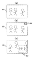
次に、図3に上記映像確認に至るフローに対応するLCD画面構成を示す。 Next, FIG. 3 shows an LCD screen configuration corresponding to the flow up to the video confirmation.
図3は、本実施形態によるビデオカメラの表示画面概略図である。 FIG. 3 is a schematic view of a display screen of the video camera according to the present embodiment.
図3において、(a)は、S102の録画ボタン押し下げ時の表示画面であり、メイン画面301を示している。(b)は、S111で第2のメモリ109に所定量の映像データが蓄積された直後の表示画面を表す。ここで、メイン画面301中に記号302を表示して撮り始めの映像の確認が可能であることを告知する。
3A shows a display screen when the recording button is pressed in S102, and shows a
(c)は、映像確認中の画面構成である。メイン画面301として現在撮影中の映像を、サブ画面303には第2のメモリ109に蓄積されている撮影開始直後から数秒分の映像を表示する。
(C) is a screen configuration during video confirmation. The
撮影開始直後の映像の確認は、撮影が始まり第2のメモリ109への映像データの蓄積が始まった後はいつでも可能となる。従って、撮影途中であっても確認ができるので、撮り始めの映像を確認して撮影を中止し、次の録画タイミングのための準備をすることが可能となる。
Confirmation of the video immediately after the start of shooting can be performed any time after shooting starts and accumulation of video data in the
このように、本実施形態では、記録媒体に記録する映像を保持するメモリとは別に撮影開始時点から一定時間分の映像を保持する専用のメモリに保持して撮影中に表示するので、装置の構成及び制御が簡潔となる。 As described above, in the present embodiment, since the video is recorded in the dedicated memory that holds the video for a certain time from the shooting start time separately from the memory that holds the video to be recorded on the recording medium, Configuration and control are simplified.
(第2の実施形態)
以下、本発明に係る第2の実施形態について図面(図4,5)を参照して説明する。
(Second Embodiment)
Hereinafter, a second embodiment of the present invention will be described with reference to the drawings (FIGS. 4 and 5).
図4は、本実施形態によるビデオカメラの装置の概略を示すブロック図である。図5は、同じくビデオカメラの動作フロー図である。 FIG. 4 is a block diagram showing an outline of the apparatus of the video camera according to the present embodiment. FIG. 5 is an operation flowchart of the video camera.
まず、各部の内部構成について説明する。なお、図1と同一の番号を付するブロックは、その作用も同様であり、説明を省略する。 First, the internal configuration of each part will be described. Note that the blocks denoted by the same reference numerals as those in FIG.
本実施形態の装置は、半導体メモリを記録媒体として用いるものである。図4において130は、映像データを記録するフラッシュメモリである。131はメモリを制御するメモリ制御部である。
The apparatus of this embodiment uses a semiconductor memory as a recording medium. In FIG. 4, 130 is a flash memory for recording video data. A
図4、図5により動作及び撮影フローを説明する。 The operation and shooting flow will be described with reference to FIGS.
S501で電源投入後の起動が完了してスタンバイ状態となり、S502で録画ボタンが押されると撮影が開始される。制御マイコン110が圧縮伸長処理部105に符号化の開始を指示すると、S503で映像の符合化が開始される。また、撮影中の映像はS504においてLCD106等の表示器に表示される。
In S501, the start-up after power-on is completed and the camera enters a standby state. When the recording button is pressed in S502, shooting is started. When the
符合化された映像は、S505においてメモリ制御部131を介してフラッシュメモリ130に記録される。撮影中は、映像の内容に応じた転送レートで逐次フラッシュメモリ130に符号化された映像データが記録されている。
The encoded video is recorded in the
S507で録画ボタンが再度押し下げられると撮影が停止される。S508で圧縮伸長処理部105に対して処理の停止が制御マイコン110により指示され、映像の符合化が停止する。
When the recording button is pressed again in S507, shooting is stopped. In step S508, the
また、S509で圧縮された映像が全てフラッシュメモリ130に記録されたことが確認され記録が完了となる。そしてS516で1回の撮影が終了する。
Further, it is confirmed that all the videos compressed in S509 are recorded in the
ここで、S505でフラッシュメモリ130への蓄積が開始される際に、映像データが記録される先頭のアドレス値を制御マイコン110は保持しておく。
Here, when accumulation in the
そして、S512において確認ボタンが押し下げられると、制御マイコン110が保持している先頭アドレス値をメモリ制御部131に指示すると、フラッシュメモリ130の指定アドレスから映像データが読み出される。読み出された映像は、圧縮伸長部105で伸長処理され映像表示処理部107で変換された後にLCD106に表示される。
When the confirmation button is pressed in S512, when the start address value held by the
さらに、S515において再度確認ボタンが押されると、確認映像の表示が停止する。 Furthermore, when the confirmation button is pressed again in S515, the display of the confirmation video is stopped.
本実施形態の装置においては、記録媒体としてフラッシュメモリを用いており、撮り始めを確認する際の映像はそのフラッシュメモリの一部を読み出して生成し表示している。従って、確認映像の容量はフラッシュメモリの容量と同じであるので、数秒分に限定されることがないので、長時間の確認が可能となる。 In the apparatus of the present embodiment, a flash memory is used as a recording medium, and a video when confirming the start of shooting is generated by reading a part of the flash memory and displaying it. Therefore, since the capacity of the confirmation video is the same as the capacity of the flash memory, the confirmation video is not limited to several seconds, so that confirmation can be performed for a long time.
このように、本実施形態では、撮影した映像データを記録している記録媒体から、撮影した記録データを撮影開始時点から任意時間分撮影中に確認することができる。データを一時的に保持するメモリやディスクドライブ機構を有せず、より簡単な構成にすることができる。 As described above, in the present embodiment, it is possible to confirm the recorded recording data from the recording medium on which the captured video data is recorded during imaging for an arbitrary time from the imaging start time. There is no memory or disk drive mechanism for temporarily storing data, and a simpler configuration can be achieved.
(第3の実施形態)
以下、本発明に係る第3の実施形態について図面(図6〜10)を参照して説明する。
(Third embodiment)
A third embodiment according to the present invention will be described below with reference to the drawings (FIGS. 6 to 10).
図6は、本実施形態におけるビデオカメラの装置の概略を示すブロック図である。 FIG. 6 is a block diagram showing an outline of the apparatus of the video camera in the present embodiment.
まず、各部の内部構成について説明する。なお、図1と同一の番号を付するブロックは、その作用も同様であり、説明を省略する。ただし、図1の第2のメモリ109は存在せず、第1のメモリ108を単一のメモリとしている。
First, the internal configuration of each part will be described. Note that the blocks denoted by the same reference numerals as those in FIG. However, the
本実施形態の特徴は、実施形態1と同様の光ディスクを用いた記録再生装置で、1つのメモリで通常の撮影と撮り始め映像確認を実現するものである。 A feature of this embodiment is a recording / reproducing apparatus using the same optical disk as that of the first embodiment, which realizes normal photographing and video confirmation at the start of shooting with one memory.
最初に光ディスクを用いた間欠記録について説明する。 First, intermittent recording using an optical disk will be described.
通常映像データをメモリに転送するレートに比べて、メモリからディスクに記録する際のレートの方が速い。例えばDVD等では映像の転送レートは通常4〜6Mbpsで、ディスクへの転送レートは24Mbpsとなっている。 Compared with the rate at which normal video data is transferred to the memory, the rate at which the video data is recorded on the disk is faster. For example, in a DVD or the like, the transfer rate of video is usually 4 to 6 Mbps, and the transfer rate to the disc is 24 Mbps.
従って、圧縮された映像データがメモリに蓄積されて所定量に達するまで、ディスクドライブを休止することができる。 Therefore, the disk drive can be paused until the compressed video data is accumulated in the memory and reaches a predetermined amount.
図7は、ビデオカメラの間欠動作を示す図である。 FIG. 7 is a diagram illustrating the intermittent operation of the video camera.
図7において、(a)はメモリのデータ蓄積量を示し、(b)はドライブの休止、起動の制御信号、(c)は記録タイミングの制御信号である。(a)において、間欠動作のために、メモリ内のデータ蓄積量に対してしきい値Thが設定されている。ドライブが休止している間、メモリ108にはデータが蓄積され、時刻t1でデータ蓄積量がしきい値Thに達すると、ドライブを起動してサーボ制御し、所定のトラックにシークする。シークが完了すると時刻t2で記録開始してメモリ108内のデータを記録して時刻t3で再び休止する。具体的にはスピンドルモータ121を停止して、ディスク120の回転を止める、またはサーボ制御を停止して、レーザーを消灯するなどによりディスクドライブの消費電力を低減する。
In FIG. 7, (a) shows the amount of data stored in the memory, (b) is a drive stop / start control signal, and (c) is a recording timing control signal. In (a), a threshold Th is set for the amount of data stored in the memory for intermittent operation. While the drive is idle, data is accumulated in the
以上のように休止と起動を繰り返しながら記録を行う。 As described above, recording is performed while repeating the pause and activation.
次に、メモリの読み書きの概略を説明する。 Next, an outline of memory reading and writing will be described.
図8は、ビデオカメラのメモリ制御を示す図である。 FIG. 8 is a diagram showing memory control of the video camera.
図8において、図7の各時刻t2,t3,t5及びt6の時点のメモリ108に対する映像データの書込み状況とメモリ108からディスク120への読み出し状況を表したものである。
FIG. 8 shows a video data writing state to the
時刻t2は、ドライブが起動してディスク120に書き込みを始める直前の状態である。図8に示すように時刻t2においては、映像データはアドレス0〜アドレスM1まで書き込まれている。ディスク120への読み出しは、未だ行われていない。 Time t2 is a state immediately before the drive is started and writing to the disk 120 is started. As shown in FIG. 8, at time t2, the video data is written from address 0 to address M1. Reading to the disk 120 has not been performed yet.
時刻t3では、映像データはアドレスM5まで書き込まれている。またディスク120への1回目の読み出しが行われアドレス0〜アドレスM2までのデータがディスク120に記録された状態である。 At time t3, the video data is written up to address M5. In addition, the first reading to the disk 120 is performed, and data from address 0 to address M2 is recorded on the disk 120.
従って、メモリ108のアドレス0〜アドレスM2までのデータは上書きすることが可能となる。
Therefore, data from address 0 to address M2 in the
時刻t5では、映像データの書込みはアドレスM5から上限のアドレスMに到達した後に、続けてアドレス0〜M3まで進んだ状態である。 At time t5, the writing of the video data is in a state of continuing from address M5 to address 0 to M3 after reaching the upper limit address M.
一方、ドライブは図7に示すように時刻t3〜t4まで休止した状態であり、時刻t5で再度起動した直後であるので、メモリ上の位置は前回の時刻t3の読み出しアドレスM2のままである。 On the other hand, as shown in FIG. 7, the drive is in a state of being suspended from time t3 to t4, and immediately after being restarted at time t5, the position on the memory remains the read address M2 at the previous time t3.
時刻t5からディスク120への2回目の記録が始まり、時刻t6までにアドレスM2〜アドレスMまで記録し、続けてアドレス0〜アドレスM4までの映像データを読み出してディスク120に記録している。 The second recording on the disk 120 starts from time t5, recording is performed from address M2 to address M by time t6, and video data from address 0 to address M4 is subsequently read and recorded on the disk 120.
上記のシーケンスを繰り返すことにより間欠的に映像データをディスク120に記録している。 Video data is recorded on the disc 120 intermittently by repeating the above sequence.
図9は、ビデオカメラの動作フロー図である。 FIG. 9 is an operation flowchart of the video camera.
動作フローは、撮影開始直後の撮り始め映像を確認する際のフローを示す。 The operation flow shows a flow when confirming a start video immediately after the start of shooting.
電源が投入されて初期立ち上げが完了しS901で動作スタートする。S902において録画ボタンが押し下げられると、S903で映像の圧縮符合化が開始される。また、撮影中の映像はS904においてLCD106に表示される。
The power is turned on, the initial startup is completed, and operation starts in S901. When the recording button is pressed in S902, video compression encoding is started in S903. Further, the image being shot is displayed on the
符号化された映像データはS905においてメモリ108に蓄積される。
The encoded video data is stored in the
ここで、メモリ内108の映像データの書込み及びディスク120への読み出しの概略を説明する。
Here, an outline of writing video data in the
図10は、ビデオカメラのメモリ制御を示す図である。 FIG. 10 is a diagram illustrating memory control of the video camera.
本実施形態では、1つのメモリで通常映像の間欠動作と、撮り始め映像の確認動作を実現するために、蓄積開始アドレス0〜Mxまでは最初の1回目のみ映像データを書込み、2回目以降は書込み禁止に設定する。図10の(A)は1回目の書込みであるので、アドレスM1まで映像データが書き込まれた状態である。 In the present embodiment, in order to realize the normal video intermittent operation and the shooting start video confirmation operation in one memory, the video data is written only for the first time from the storage start address 0 to Mx, and the second time and thereafter. Set to write-protection. Since (A) in FIG. 10 is the first writing, the video data has been written up to the address M1.
S906でメモリ108に蓄積された映像をディスク120に記録する。図10の(B)は、ディスク120に1回目の記録が行われた直後の状態である。映像データの書込みアドレスはM5まで進行し、ディスク120へはアドレス0〜M2までの映像データが記録されている。
In S906, the video stored in the
従って、従来ならアドレス0〜M2まで映像データの上書きが可能であるが、本実施形態ではアドレス0〜アドレスMxまでの映像データは撮り始め確認用に保持するので上書き禁止エリアに設定されている。 Therefore, conventionally, video data can be overwritten from address 0 to M2, but in this embodiment, video data from address 0 to address Mx is held for overwriting prohibition because it is held for confirmation of the start of shooting.
よって、図10の(C)では、アドレスM5〜アドレスMに達した後に、アドレスMxから続きの映像を上書きしている。ここではアドレスM3まで映像データが書き込まれている。 Therefore, in (C) of FIG. 10, after reaching the addresses M5 to M, the subsequent video from the address Mx is overwritten. Here, video data is written up to address M3.
図10の(D)では、2回目のディスク120への記録が行われアドレスM2〜アドレスM、さらにアドレスMx〜アドレスM4までの映像データが読み出されてディスク120に記録される。 In FIG. 10D, recording is performed on the disk 120 for the second time, and video data from address M2 to address M and further from address Mx to address M4 is read and recorded on the disk 120.
従って、通常撮影中でも撮り始めの映像データはアドレス0〜アドレスMxに保持される。 Therefore, video data at the start of shooting is held at addresses 0 to Mx even during normal shooting.
図9のS907で録画ボタンが再度押し下げられると撮影は停止し、S908で映像の圧縮符号化が停止される。次にメモリ108に保持されている残りの映像が全てディスク120に記録されるとS914で撮影の終了となる。
When the recording button is pressed again in S907 in FIG. 9, shooting is stopped, and in S908, video compression encoding is stopped. Next, when all the remaining videos stored in the
また、S912で図6の操作ボタン111の中の確認ボタンが押されると、S913においてメモリ108のアドレス0〜アドレスMxの映像データが圧縮伸長処理部105で伸長される。そして映像表示処理部107で表示信号に変換後にLCD106に表示される。
When the confirmation button in the operation button 111 in FIG. 6 is pressed in S912, the video data at addresses 0 to Mx in the
表示映像は、図3と同様であるので省略する。 The display video is the same as in FIG.
ただし、図3ではメイン画面の一部にサブ画面として撮り始めの映像を表示しているが、画面を2分割して表示することも当然可能である。また、メインとサブの画面を切り換えて、撮り始めの映像を大きく表示するように切り換えるように変更することもできる。 However, in FIG. 3, the video at the beginning of shooting is displayed as a sub-screen on a part of the main screen, but it is naturally possible to display the screen by dividing it into two. It is also possible to change the main and sub screens so that the video at the beginning of shooting is displayed in a large size.
本実施形態では、光ディスクを用いたビデオカメラで、通常のメモリのみを使用し、光ディスクに間欠記録する際に用いるメモリの一部を一定時間分の映像データの保持に割り当てている。それにより、撮り始めの映像の保持と、撮影中の表示を実現しているので、低コストで機能の実現を図ることができる。 In this embodiment, a video camera using an optical disk uses only a normal memory, and a part of the memory used for intermittent recording on the optical disk is assigned to hold video data for a certain period of time. Accordingly, since the video at the beginning of shooting is held and the display during shooting is realized, the function can be realized at low cost.
101…レンズ
102…撮像センサ
103…映像信号処理部
104…レンズドライバ
105…圧縮伸長処理部
106…LCD
107…映像表示処理部
108…第1のメモリ
109…第2のメモリ
110…制御マイコン
111…操作ボタン
120…ディスク
121…スピンドルモータ
122…ピックアップ
123…ドライブ信号処理部
124…送りモータ
125…ピックアップドライバ
DESCRIPTION OF SYMBOLS 101 ... Lens 102 ...
DESCRIPTION OF
Claims (2)
前記第1のメモリ手段に保持された映像を記録媒体に記録する手段と、
前記撮影開始から一定時間分の映像を保持する第2のメモリ手段と、
前記撮影中の映像を、前記記録媒体に記録しながらメイン画面に表示すると共に、前記撮影中の映像を、前記記録媒体に記録しながら撮影開始から一定時間分の映像を前記第2のメモリ手段から読み出し、前記メイン画面の一部であるサブ画面に表示する表示手段を有することを特徴とするビデオカメラ。 First memory means for holding an image being shot;
Means for recording the video held in the first memory means on a recording medium;
Second memory means for holding video for a predetermined time from the start of shooting;
The second memory means displays the video being shot on the main screen while recording the video on the recording medium, and the video for a predetermined time from the start of shooting while recording the video being shot on the recording medium. A video camera comprising: display means for reading from the display and displaying on a sub-screen that is a part of the main screen.
前記第1のメモリ手段に保持された映像を記録媒体に記録する手段と、
前記撮影開始から一定時間分の映像が保持されている前記第1のメモリ手段の領域を上書き禁止エリアに設定する手段と、
前記撮影中の映像を、前記記録媒体に記録しながらメイン画面に表示すると共に、前記撮影中の映像を、前記記録媒体に記録しながら撮影開始から一定時間分の映像を前記第1のメモリ手段から読み出し、前記メイン画面の一部であるサブ画面に表示する表示手段を有することを特徴とするビデオカメラ。 First memory means for holding an image being shot;
Means for recording the video held in the first memory means on a recording medium;
Means for setting an area of the first memory means in which video for a certain period of time from the start of photographing is held as an overwrite prohibition area;
The first memory means displays the video being shot on the main screen while recording the video on the recording medium, and the video for a predetermined time from the start of shooting while recording the video being shot on the recording medium. A video camera comprising: display means for reading from the display and displaying on a sub-screen that is a part of the main screen.
Priority Applications (2)
| Application Number | Priority Date | Filing Date | Title |
|---|---|---|---|
| JP2006103227A JP4865386B2 (en) | 2006-04-04 | 2006-04-04 | Video camera |
| US11/692,295 US8050532B2 (en) | 2006-04-04 | 2007-03-28 | Digital camcorder having display unit |
Applications Claiming Priority (1)
| Application Number | Priority Date | Filing Date | Title |
|---|---|---|---|
| JP2006103227A JP4865386B2 (en) | 2006-04-04 | 2006-04-04 | Video camera |
Publications (3)
| Publication Number | Publication Date |
|---|---|
| JP2007281689A JP2007281689A (en) | 2007-10-25 |
| JP2007281689A5 JP2007281689A5 (en) | 2009-05-21 |
| JP4865386B2 true JP4865386B2 (en) | 2012-02-01 |
Family
ID=38559061
Family Applications (1)
| Application Number | Title | Priority Date | Filing Date |
|---|---|---|---|
| JP2006103227A Expired - Fee Related JP4865386B2 (en) | 2006-04-04 | 2006-04-04 | Video camera |
Country Status (2)
| Country | Link |
|---|---|
| US (1) | US8050532B2 (en) |
| JP (1) | JP4865386B2 (en) |
Families Citing this family (5)
| Publication number | Priority date | Publication date | Assignee | Title |
|---|---|---|---|---|
| JP4770929B2 (en) * | 2009-01-14 | 2011-09-14 | ソニー株式会社 | Imaging apparatus, imaging method, and imaging program. |
| US8337397B2 (en) | 2009-03-26 | 2012-12-25 | Intuitive Surgical Operations, Inc. | Method and system for providing visual guidance to an operator for steering a tip of an endoscopic device toward one or more landmarks in a patient |
| US10004387B2 (en) | 2009-03-26 | 2018-06-26 | Intuitive Surgical Operations, Inc. | Method and system for assisting an operator in endoscopic navigation |
| JP6344986B2 (en) * | 2014-06-10 | 2018-06-20 | キヤノン株式会社 | Display control apparatus and control method thereof |
| CN111352507A (en) * | 2020-02-27 | 2020-06-30 | 维沃移动通信有限公司 | Information prompting method and electronic equipment |
Family Cites Families (10)
| Publication number | Priority date | Publication date | Assignee | Title |
|---|---|---|---|---|
| JPH07298307A (en) * | 1994-04-28 | 1995-11-10 | Canon Inc | Image recording and reproducing device |
| JP3528524B2 (en) | 1997-07-10 | 2004-05-17 | ソニー株式会社 | Recording / reproducing apparatus, recording / reproducing method, and recording medium |
| JPH11308488A (en) * | 1998-04-17 | 1999-11-05 | Canon Inc | Video camera, video camera system, photographing method, video signal processing method and storage medium |
| JP4646046B2 (en) * | 1998-11-02 | 2011-03-09 | 株式会社ニコン | Recording / playback device |
| JP3774343B2 (en) | 1999-10-04 | 2006-05-10 | 株式会社日立製作所 | Video camera |
| JP3958084B2 (en) * | 2002-02-08 | 2007-08-15 | キヤノン株式会社 | Optical recording / reproducing method |
| US7656429B2 (en) * | 2004-02-04 | 2010-02-02 | Hewlett-Packard Development Company, L.P. | Digital camera and method for in creating still panoramas and composite photographs |
| JP2006080651A (en) * | 2004-09-07 | 2006-03-23 | Canon Inc | Imaging apparatus and control method therefor |
| US20060119724A1 (en) * | 2004-12-02 | 2006-06-08 | Fuji Photo Film Co., Ltd. | Imaging device, signal processing method on solid-state imaging element, digital camera and controlling method therefor and color image data generating method |
| JP4444912B2 (en) * | 2005-11-17 | 2010-03-31 | キヤノン株式会社 | Video camera |
-
2006
- 2006-04-04 JP JP2006103227A patent/JP4865386B2/en not_active Expired - Fee Related
-
2007
- 2007-03-28 US US11/692,295 patent/US8050532B2/en not_active Expired - Fee Related
Also Published As
| Publication number | Publication date |
|---|---|
| JP2007281689A (en) | 2007-10-25 |
| US8050532B2 (en) | 2011-11-01 |
| US20070230916A1 (en) | 2007-10-04 |
Similar Documents
| Publication | Publication Date | Title |
|---|---|---|
| JP2001111963A (en) | Recording and reproducing method for video camera utilizing optical disk | |
| US7444062B2 (en) | Playback system | |
| JP4865386B2 (en) | Video camera | |
| JP2006287596A (en) | Camera apparatus with animation reproduction function in a plurality of image selection screens | |
| JP4042411B2 (en) | Data recording apparatus, data reproducing apparatus, data recording / reproducing method, and imaging apparatus | |
| JP4343765B2 (en) | Recording apparatus and reproducing apparatus | |
| TWI357593B (en) | ||
| US8005340B2 (en) | Data recording apparatus | |
| JP2005341391A (en) | Image-reproducing device and method, and program | |
| US20060140088A1 (en) | Recording method and recording device | |
| JP4058154B2 (en) | Video recording / reproducing apparatus and video recording / reproducing method | |
| JP2006221697A (en) | Optical disk recording apparatus and optical disk recording method | |
| JP4621163B2 (en) | Video recording / playback device | |
| JP2005339645A (en) | Recording and reproducing device, its recording and reproducing method, program and recording medium | |
| JP5312104B2 (en) | Imaging device | |
| JP3826134B2 (en) | Recording device | |
| JP4836273B2 (en) | Video imaging device | |
| JP2008011421A (en) | Camera device | |
| JP4234662B2 (en) | Electronic device and data recording method thereof | |
| JP2007157256A (en) | Recording system | |
| JP2007096983A (en) | Digital camera | |
| JP4577346B2 (en) | Data recording apparatus, data reproducing apparatus, data recording / reproducing method, and imaging apparatus | |
| JP5984546B2 (en) | Image processing apparatus, image processing method, and storage medium | |
| JP4569662B2 (en) | Information recording apparatus and information recording method | |
| JP4281803B2 (en) | Information recording apparatus and information recording method |
Legal Events
| Date | Code | Title | Description |
|---|---|---|---|
| RD04 | Notification of resignation of power of attorney |
Free format text: JAPANESE INTERMEDIATE CODE: A7424 Effective date: 20080207 |
|
| RD01 | Notification of change of attorney |
Free format text: JAPANESE INTERMEDIATE CODE: A7421 Effective date: 20090220 |
|
| A521 | Request for written amendment filed |
Free format text: JAPANESE INTERMEDIATE CODE: A523 Effective date: 20090406 |
|
| A621 | Written request for application examination |
Free format text: JAPANESE INTERMEDIATE CODE: A621 Effective date: 20090406 |
|
| RD04 | Notification of resignation of power of attorney |
Free format text: JAPANESE INTERMEDIATE CODE: A7424 Effective date: 20100201 |
|
| RD01 | Notification of change of attorney |
Free format text: JAPANESE INTERMEDIATE CODE: A7421 Effective date: 20100630 |
|
| A977 | Report on retrieval |
Free format text: JAPANESE INTERMEDIATE CODE: A971007 Effective date: 20101217 |
|
| A131 | Notification of reasons for refusal |
Free format text: JAPANESE INTERMEDIATE CODE: A131 Effective date: 20110208 |
|
| A521 | Request for written amendment filed |
Free format text: JAPANESE INTERMEDIATE CODE: A523 Effective date: 20110407 |
|
| TRDD | Decision of grant or rejection written | ||
| A01 | Written decision to grant a patent or to grant a registration (utility model) |
Free format text: JAPANESE INTERMEDIATE CODE: A01 Effective date: 20111108 |
|
| A01 | Written decision to grant a patent or to grant a registration (utility model) |
Free format text: JAPANESE INTERMEDIATE CODE: A01 |
|
| A61 | First payment of annual fees (during grant procedure) |
Free format text: JAPANESE INTERMEDIATE CODE: A61 Effective date: 20111110 |
|
| FPAY | Renewal fee payment (event date is renewal date of database) |
Free format text: PAYMENT UNTIL: 20141118 Year of fee payment: 3 |
|
| FPAY | Renewal fee payment (event date is renewal date of database) |
Free format text: PAYMENT UNTIL: 20141118 Year of fee payment: 3 |
|
| LAPS | Cancellation because of no payment of annual fees |