JP4846885B2 - A stimulating simulator for distributed process control systems. - Google Patents
A stimulating simulator for distributed process control systems. Download PDFInfo
- Publication number
- JP4846885B2 JP4846885B2 JP53626497A JP53626497A JP4846885B2 JP 4846885 B2 JP4846885 B2 JP 4846885B2 JP 53626497 A JP53626497 A JP 53626497A JP 53626497 A JP53626497 A JP 53626497A JP 4846885 B2 JP4846885 B2 JP 4846885B2
- Authority
- JP
- Japan
- Prior art keywords
- simulator
- processing units
- distributed processing
- sensor signal
- distributed
- Prior art date
- Legal status (The legal status is an assumption and is not a legal conclusion. Google has not performed a legal analysis and makes no representation as to the accuracy of the status listed.)
- Expired - Lifetime
Links
Images


Classifications
-
- G—PHYSICS
- G05—CONTROLLING; REGULATING
- G05B—CONTROL OR REGULATING SYSTEMS IN GENERAL; FUNCTIONAL ELEMENTS OF SUCH SYSTEMS; MONITORING OR TESTING ARRANGEMENTS FOR SUCH SYSTEMS OR ELEMENTS
- G05B17/00—Systems involving the use of models or simulators of said systems
- G05B17/02—Systems involving the use of models or simulators of said systems electric
Description
発明の分野
本発明は分散プロセス制御システムの動作をシミュレーションするミュレータに関する。
背景情報
分散プロセス制御システムはエネルギー、金属及び水/排水の分野におけるプロセスを含む(これらに限定されない)複雑なプロセスの制御に常用されるようになっている。エネルギー分野は、原子力及び原子力以外の発電プロセス制御及び発電所用コンピュータの用途を含む。分散プロセス制御システムは、各々がプロセス全体のある特定の部分の制御を担当する多数の分散処理ユニット(DPU)を有する。これらのDPUは通常、プロセス制御ソフトウエアを実行することにより、プロセスの担当部分から受けるセンサー信号及びオペレータからの信号に応答して、担当部分の制御信号を発生するデジタルプロセッサを備えている。個々のDPUは、ネットワーク通信手段により相互に且つオペレータ・コンソールに接続されている。任意のDPUが発生し他のDPUが必要とするパラメータ値は、通信ネットワークを介して送信される。
プラントで発生されるセンサー信号は通常、アナログまたは論理信号である。各DPUは、アナログセンサー信号をデジタルセンサー信号に変換するアナログ−デジタルコンバータを備え、デジタルセンサー信号を記憶する。DPU内のデジタルプロセッサは定期的に、デジタルセンサー信号を取り出してパラメータ値に変換し、このパラメータ値は制御アルゴリズムにより使用されるか通信ネットワークを介して分散システムの他の部分へ送られる。種々のDPUにより実行される各種機能は、センサー値入力の更新につきそのDPUに応じた種々の条件を有する。例えば、制御ループの一部では入力信号をミリ秒のインターバルで更新する必要があり、またミリ秒の十分の一または百分の一のインターバルでの更新を必要とするものもあり、さらに1秒またはそれ以上でのインターバルで更新すればよいものもある。通常、同じレートでの更新が必要な機能は共通のDPUにグループ化される。その結果、種々のDPUがセンサーデータの更新につきそれぞれ異なる条件をもつのが常態となっている。
プロセス制御システムの複雑さが増すにつれて、オペレータの訓練及びプロセス制御システムの技術的仕様改善をシミュレーションするためのシミュレータに対する需要が増大している。プラントプロセス制御用シミュレータは伝統的に、プロセスとプロセス制御システムの両方のモデル(数学的ソフトウエアによる)をエミュレーションする単一のコンピュータシステムを用いている。しかしながら、分散プロセス制御システムのようなシステムのリアルタイム応答をエミュレーションし、エミュレーションされたシステムがモデル化しようとするシステムにマッチすることを証明することが容易でないことが分かっているため、分散プロセス制御システムにとってこの方式は常に満足すべきものではなかった。1994年7月29日付けの本出願人所有の米国特許出願第08/282,854号は、実際のプロセス制御ソフトウエアを用いるプラントからの実際の分散プロセスユニットを利用するシミュレータを提供することによりこの問題に対処している。プロセスは、各々が1または2以上のDPUにより制御されるプロセスの一部をシミュレーションする多数のスレーブ・シミュレータにより、マスター・シミュレータの制御下で、エミュレーションされる。センサー信号を関連のDPUに送らずに、このシステムのスレーブ・シミュレータは技術的或いは電気的変換を行って、プロセスパラメータのデジタル値を直接メモリアクセスユニットを介してDPUのデジタルプロセッサのメモリへ直接入力する。
米国特許出願第08/282,854号に記載されたシステムはプロセスと分散プロセス制御システムの両方をエミュレーションする従来型シミュレータシステムと比較すれば著しい利点を有するものであるが、依然として改良の余地がある。この従来型システムは種々のDPUが異なる制御周波数をもつことを考慮に入れていない。従って、この従来型システムの時間応答は実際のプラントのシステム応答に正確には一致しないであろう。また、プラントオペレータの多くは既に彼等のプロセスのコンピュータモデルを有するが、それをモデル化ソフトウエアを修正せずに多数のスレーブ・シミュレータと共用することは不可能である。加えて、スレーブ・シミュレータはパラメータ値を工学値としてDPUメモリに直接注入するため、DPUの変換ルーチンは実行されない。これは刺激型シミュレーションがI/Oレベルインターフェイスにおいて実際のプラントとマッチするのを保証するための重要な特徴である。
従って、分散プロセス制御システムの動作をシミュレーションする改良型シミュレータに対する需要がある。
特に、分散プロセス制御システムの実際の応答時間をより正確にシミュレーションする改良型シミュレータに対する需要がある。
また、DPUの変換ルーチンを実行する改良型シミュレータに対する需要がある。
さらに、DPUのアプリケーションソフトウエアの大掛かりな修正が不要で、実際のシステムハードウエア成分を再使用するかかる改良型シミュレータに対する需要がある。
プラントモデルコンピュータソフトウエアを大規模に修正することなく既存のコンピュータプラントモデルを利用できるかかる改良型シミュレータに対する新たな需要が存在する。
発明の概要
上記及び他の需要は、実際の分散型計測・制御システムにあるような分散処理ユニット(DPU)を用い実際のプロセス制御ソフトウエアを実行する分散プロセス制御システムのためのシミュレータに関する本発明により充足される。例えば既存のプラントモデル化コンピュータのようなモデル化手段は、そのプロセスをエミュレーションし、DPUが実際のプロセス制御ソフトウエアを用いて発生させる制御信号に応答して、好ましくはセンサー信号であるプロセス信号を発生させる。DPUはまた、オペレータコンソールにより発生されるオペレータ信号に応答する。通信手段は複数のDPU間及びDPUとオペレータコンソールの間の通信を可能にする。各DPU及びモデル化手段に接続された刺激手段は、プロセス信号をDPUへ送り込む。本発明の1つの特徴は、プロセス信号がDPUの入出力(I/O)へマッピングされるセンサー信号であり、DPUが各々のデジタルプロセッサを用いてセンサー信号をパラメータ値へ変換し、これらのパラメータ値が実際のプロセス制御ルーチンに使用され且つ/または通信手段を介して分散プロセスシステムの他の部分へ送られることである。
本発明の別の特徴として、刺激手段は、好ましくはセンサー信号であるプロセス信号を種々のDPUへそれらの所与の走査周波数で送り込む。モデル化手段及び刺激手段は反射メモリを介してデータを交換する。刺激手段はまた、各DPUが所与の周波数で発生する制御信号を読取り、それらを反射メモリを介してモデル化手段へマッピングする。
【図面の簡単な説明】
本発明は、好ましい実施例の下記の説明を添付図面に関連させて読めば、完全に理解できるであろう。
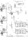
図1は、本発明による分散プロセス制御システムの刺激型シミュレータを示すブロック図である。
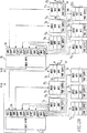
図2A及びBは、図1のシミュレータの適当な成分の相互接続態様を示すさらに詳細なブロック図である。
図3は、図1及び2のシミュレータシステムの一部である刺激型分散プロセスユニットの成分を示すブロック図である。
図4は、シミュレータシステムの一部を形成するシミュレータステーションの成分を示すブロック図である。
図5A及びBは、図4のシミュレータステーションにより実行されるシミュレータ制御プログラムのフローチャートを示す。
図6は、図4のシミュレータステーションにより実行される主ルーチンを示すブロック図である。
図7は、図4のシミュレータステーションにより実行されるマッピングルーチンのブロック図である。
好ましい実施例の詳細な説明
図1は、本発明による分散プロセス制御システムのためのシミュレータ1のアーキテクチャを示す全体図である。シミュレータ1には3つの基本的構成要素がある。まず第1に、分散プロセス計測・制御システム3は、本質的に、プラントに用いられる実際の計測・制御装置の再パッケージされた冗長性のない部分集合であり、その動作がシミュレーションされる。
計測・制御システム3は複数の分散処理ユニット(DPU)5を有し、その各々はプラント・プロセスの一部を当該技術分野において知られた態様で制御する。図示のシステムでは、DPUは12個あり、6個づつ2つのキャビネット7に収納されている。DPUは、データハイウエイ9である通信ネットワークにより共に接続されている。個々のDPU5は、ハイウエイインターフェイス11によりデータハイウエイ9に接続されている。データハイウエイはまた、DPUを1または2以上のオペレータステーション13及びエンジニア/ヒストリアンステーション15並びに他の計測・制御システムのマン−マシンインターフェイス・レイアよりなる他のワークステーションに接続する。実施例のシステムのオペレータステーション13及びエンジニア/ヒストリアンステーション15はワークステーションである。プリンタのような周辺装置17をこれらのステーションに備え付けることにより、システムの性能のハードコピー出力を作成し他の付随的な仕事を実行させることができる。
計測・制御システム3は、例えば、ウエスチングハウス社の分散処理ファミリー(WDPF)システムを使用できる。かかるシステムでは、データハイウエイ9は、リアルタイムデータの決定論的通信及びトークンをパスする民主的プロトコルによるファイル転送型通信を行うWESTNETハイウエイである。このWESTNETハイウエイ9は、ある特定の隔離仕様(ファイバーオプティックメディア等)が実現されていない点を除き実際のプラントに存在するハイウエイと同一である。ワークステーション13及び15はプリンタ17のような周辺装置を備えたユニックス・ワークステーション(WESステーション)であり、それらはプラントコンピュータ機能とマンマシンインターフェイス機能を提供し、機能的に冗長なWESステーションがない点を除き実際のプラントに存在するものと同一である。WDPFのDPU5は、計測プロセス制御装置のためのデータ収集・制御機能を提供し、その機能と数において実際のプラントに存在するものと同一であるが、再びDPUはシミュレータに必要なキャビネット数を減少させるために非冗長的であり再パッケージされている。加えて、入出力(I/O)ボードは、以下に説明するようにシミュレータのDPU5には存在しない。各DPU5は、実際のプラント装置に存在するものと同一のベース及びアプリケーションソフトウエアを含む。実施例のシステムは12個のDPUが2個のキャビネット内に収納された状態で示されているが、他の数のDPU及び構成を利用することができる。
実際のプラントだけでなくシミュレータ1においても、オペレータはオペレータステーション13を介してプロセスを制御する。シミュレータではステーションの1つに被訓練者を配置し、他のステーションをインストラクターが操作するようにできる。オペレータステーション13で発生されるオペレータ信号はデータハイウエイ9を介してDPUへ送られる。DPUはまた、データハイウエイ9を介してデータを必要に応じて交換する。DPU5は、センサー信号及びステイタス論理信号のような入力をプロセスから受取り、プロセス制御ソフトウエアにより、センサー及びステイタス信号並びにオペレータ信号に応答して、プロセスに送られる制御信号を発生させる。シミュレータ1は、プロセスがプラントモデルコンピュータ19により実現されるプロセスモデルにより代替される点を除き同じような態様で動作する。プラントの多くはシミュレーションシステムを備えており、これらのシステムは想定される異常状態及びシステムの修正を含むプラント動作を分析するために用いるかかるプラントモデルを含んでいる。シミュレータ1は、プラントシミュレータの既存のプラントモデルを用いて計測・制御システムインターフェイスが刺激されるようにする。計測・制御システム3とプラントモデルコンピュータ19の間のインターフェイスは、WESステーションのようなワークステーション23、シミュレータのワークステーションをDPU5と接続するSBUSアダプタを構成するSBUS拡張シャーシ25、及びシミュレータワークステーション23とプラントモデルコンピュータ19の間のインターフェイス27よりなるシミュレータインターフェイス21により提供される。さらに詳しく説明すると、インターフェイス27は反射メモリインターフェイス29を含む。シミュレータワークステーション23はまた、ハイウエイインターフェイス電子手段31を介してデータハイウエイ9に接続されている。
図2A及びBは、シミュレータインターフェイス21がプラントモデルコンピュータ19と計測・制御システム3のDPU5の間の通信を行う態様をさらに詳しく示すものである。図示のシミュレータ1では、シミュレータインターフェイス21のワークステーション23はSBUSアーキテクチャを用いるSUNのSPARCワークステーションである。ワークステーションのSBUS接続部33に接続されたSBUS拡張シャーシ25は、そのシャーシによりサービスを受ける6個のDPU5の各々のSBUSアダプタ35を構成する。各DPU51乃至512はMULTIBUSアーキテクチャを利用する。アダプタ371乃至3712はそれぞれのDPUを拡張シャーシ25のSBUSアダプタ35を介してシミュレータワークステーション23にインターフェイスする。DPU51乃至512はそれぞれ、プロセス制御ソフトウエアが実行されるデジタルプロセッサ(MDXボード)39を有する。DPUはまた、DPUを他のDPUとの通信のためにデータハイウエイ9に接続すると共にオペレータステーション13及びエンジニア/ヒストリアンステーション15と接続するハイウエイコントローラ(MHCボード)41を含む。各DPUはまた個別の電源43も含む。
シミュレータワークステーション23は、インターフェイス27とプラントモデルコンピュータ19の両方の中にある反射メモリ29を介してプラントモデルコンピュータ19と通信を行う。プラントモデルコンピュータ19とインターフェイス27の中の反射メモリ29間は、光ファイバリング通信ネットワーク30を介して接続されている。プラントモデルコンピュータ19と反射メモリ29はVMEバスを有するため、インターフェイス27のバスアダプタ45とワークステーション23のSBUS接続部33のアダプタ47とは、データと制御信号を交換するためのハードウエアインターフェイスを提供する。図1に関連して説明したように、インターフェイス31はシミュレータワークステーション23をデータハイウエイ9と接続する。これは別のSBUS接続33を介して行われる。シミュレータワークステーション23とプラントモデルコンピュータ19の間のインターフェイスを構成する反射メモリ29は、プラントモデルコンピュータと計測・制御システム3との間のプロトコールのないデータ転送を可能にする。
シミュレータワークステーション23の主要な機能は、プラントモデルコンピュータ19とDPU5との間でデータ値とステータス情報をマッピングすることと、実行/停止、初期状態(IC)セットのロード/セーブ、スナップショット、バックトラック及びその他に応答することである。停止制御機能は、被訓練者と一緒に検討しまた分析を行うために任意の時点におけるシミュレータの停止を可能にする。セーブ機能は、システムの動作の任意の点において1組の状態を記憶し、これを後で思い出すことができる。ロード機能は、指定されたセーブ機能の初期状態をDPUにロードして、選択された状態でシミュレータをスタートさせる。スナップショット機能は、初期状態が進行中にセーブされオペレータにとって透明である点を除き、セーブ機能と同じである。バックトラック機能があると、インストラクタは被訓練者の成績或いはプラント動作の進行を検討するために一連のスナップショットを思い出すことができる。
図3は、DPU5の適当な構造をより詳細に示すものである。DPUの心臓部はMDXボード39であり、その上に中央処理ユニット(CPU)49及びデータベースメモリ51を備えたマイクロコンピュータよりなるデジタルプロセッサが構成してある。MDXボード39はまた、メモリがマッピングされた入出力(I/O)インターフェイス(DIOB)53を有する。このDIOBインターフェイス53は、実際のプラント(図示せず)のI/Oカードにより通常走査されるアナログ信号及び論理信号のアナログからデジタルへの等価信号を含む。刺激型システムインターフェイスでは、シミュレーションされるインターフェイスがこのメモリ53に、プラントモデルコンピュータ19から受取るセンサー値に対応する適当に変換されたデジタル値を入力する。プロセッサ49は定期的に、デジタル化センサー信号を制御ソフトウエアのアルゴリズムを実行するために用いるためにDIOB53から取り出す。これらのアルゴリズムは制御信号を発生させ、制御信号はその後プラントの弁モータ及び他の能動成分へ出力するためにDIOB53に記憶される。勿論、シミュレータにおいて、これらの成分及び制御中のプロセスはプラントモデルコンピュータ19においてエミュレーションされる。
データベースメモリ51は、分散プロセス制御ソフトウエアが発生させる種々のポイント値を記憶する。叙上のように、一部のDPUが発生するこれらのデータポイントの一部は他のDPUによっても使用される。これらのデータポイント値の交換は、MHCボード41に取り付けたネットワークコントローラにより通信ネットワーク9を介して実現される。MHCボード41はプロプラエタリバス55を介してMDXボードと通信する。
前に述べたように、DPUが実行する各種のルーチンは異なるI/O及び制御周波数を有する。通常、共通のI/O周波数を有するルーチンは単一のDPUにおいて一纏めにされる。I/O周波数はDIOBメモリ53の更新レートを決定する。制御周波数は、CPU49がDIOB53に対して読取り及び書込みを行うレートを決定する。本発明によると、シミュレータステーション23は、プラントモデルコンピュータ19が発生するセンサー信号値をDIOB53内に直接、関連DPU5のI/O周波数でマッピングする。これは、MULTIBUS57と、シミュレータステーション23のSBUSとDPUのMULTIBUS57との間で信号をやり取りするインターフェイス37とを用いることにより実現する。かくして、シミュレータステーション23は、データハイウエイ9を介する通信において固有の呼び出し時間を導入することなく、信号データをDPUに対して直接読み書きすることができる。この直接インターフェイスにより、シミュレータステーション23はDPUとの通信を実際のシステムタイミング構成または入出力走査、制御計算等と周波数マッチングすることができる。これにより、シミュレータの時間応答特性が確実にプラントの時間応答特性と同一になる。この直接のインターフェイスはまた、実行/停止、ロード/セーブ、初期状態セット、スナップショット、バックトラック等のようなシミュレータの制御機能に対する応答を単純化する。例えば、実行/停止はDPUの入出力走査及び制御タスクを可能化/中断することにより制御される。セーブ機能は、データベースメモリ51及びDIOBメモリ53のスナップショットを初期状態(IC)数を基準に用いてシミュレータステーション23へ送ることにより実現される。ロード機能は、初期状態セットをデータベースメモリ51及びDIOBメモリ53へ直接ロードすることにより実現される。バックトラック機能は、入出力セットをDPUへ逐次転送することにより実現される。
図4は、シミュレータワークステーション23の関連要素を示す。図示のワークステーション23は、CPU59とランダムアクセスメモリ(RAM)を有する。ワークステーションはまた、初期状態ファイル及び他の情報を記憶させる内部ハードディスク63を有する。シミュレータステーション23はSBUS65を有し、これはSBUSコネクタ33及びSBUS拡張シャーシ(図4には図示せず)を介してDPU5とインターフェイスされる。シミュレータステーション23は、反射メモリ29及びSBUSアダプタ27を介してプラントモデルコンピュータ19と通信する。また、シミュレータステーション23は、WESTNETハイウエイ31及びSBUSコネクタ33を介してデータハイウエイ9と通信する。かくして、シミュレータステーション23は、プラントモデルコンピュータ19と各DPU5の間の単一接続を行う。このため、シミュレータの既存のプラントモデルコンピュータ19を使用すると便利である。
図5は、シミュレータワークステーション23により実行されるSIM_CONTROLルーチン67のフローチャートを示す。69において最初にコールされると、そのルーチンを所望のレートで繰り返しリコールする構成可能なタイマーのセットアップを含む初期化タスクが実行される。シミュレータワークステーション23の内部におけるタスク間通信を管理するために、共有メモリも形成される。その後、プラントモデルコンピュータからの制御フラッグが71においてクリアされる。これは、モデルが停止状態にあった場合における停止フラッグのクリアを含まない。シミュレータワークステーションにより実行される他のプロセスも71でスタートする(以下に説明するSIM_MAPタスクを含む)。
その後、ルーチンは73において、内部タイマーが発生する割込みに対して待機する。タイマーがタイムアウトすると、75において実行/停止フラッグがチェックされ、それが停止にセットされておれば、77においてDPU5が停止される。これは、各DPUのDIOB53に制御ビットをセットすることにより行われる。79においてセーブ(書込み)フラッグが検出され、81において初期状態(IC)数が範囲内にあることが判明すると、シミュレータワークステーションは83に示す多数の機能を実行する。これは、71において形成されたプロセスを最初に停止しDPU5を停止することを含む。その後、データベースメモリ51及びDIOB53に記憶されたデータがシミュレータワークステーションのファイルにセーブされる。この後、システムはセーブコマンド以前の実行または停止状態に戻り、シミュレータワークステーションの停止されたプロセスが継続する。初期状態(IC)数が範囲内にない場合、85においてプロセスエラーが発生され、データハイウエイを介してオペレータステーションへ送られる。87においてロード(リセット)フラッグがセットされ、89において初期状態(IC)数が範囲内にあることが判明すると、91に示すシーケンスが始動される。これは、71において形成されたプロセスの停止及びDPUの停止を含む。その後、選択された初期状態(IC)数のもとで記憶されたデータがDIOBメモリ53及びDPU5のデータベースメモリ51へロードされる。そしてDPUがロードフラッグが検知されたときに存在する実行または停止状態へ戻り、シミュレータワークステーションにおける停止されたプロセスが継続する。これらのステップが完了すると、ルーチンは73に戻って次の時間割込みを待機する。89において初期状態(IC)数が範囲内にないことが分かると、ルーチンが次の割込みを待つため73へ戻る以前に93においてプロセスエラー表示を発生する。同様に、87においてロードフラッグがセットされなければルーチンは73へ戻る。
図6はシミュレータの主ルーチンSIM_MAIN95のフローチャートを示す。この主ルーチンは種々のDPUの走査周波数を決定し、97においてこれらの走査レートに基づきデータをソートファイルに分離する。その後、99において、図7に示すマッピングルーチン101を含む子供プロセスを生み出す。このルーチン101は、センサー信号を含むプラントモデルコンピュータからのデータを各DPUの与えられた入出力周波数で適当なDPUへマッピングする。かくして、このルーチンは各走査周波数に対して繰り返される。まず第1に、103において、シミュレータステーション23のメモリのデータポイントを初期化することによりデータ構造が初期化される。シミュレータステーションは定期的に、タイミング信号を通信インターフェイス9へ放送することにより分散システムの同期化を行う。105において放送時間になったことが分かると、107においてタイミング信号が放送される。いかなる場合でも、109において、ルーチンは反射メモリからプラントモデルコンピュータが発生するデータとDPUからのデータを収集する。プラントモデルコンピュータからのデータは、111において適当なDPUへ転送され、また逆方向へ送られる。その後、113において、ルーチンは周波数に基づき次のサイクルを待機する。上述したように、与えられた各DPU周波数に対して同じようなルーチンが実行される。同一の周波数を与えられたDPUの全てに対して同じルーチンが作用することが分かる。
上述の刺激型シミュレータインターフェイスのアーキテクチュアは、同一機能のエミュレーション及び米国特許出願第08/282,854号に記載された分散プロセス制御シミュレータに対して多くの利点を与えるものである。刺激型のエミュレーションに対する主要な利点の1つは、システムがプラントにおいて使用される同じプロセス制御システムを実際に表わすことである。かくして、刺激型システムは、実際のプラントを、マンマシンインターフェイス(ウインドウ、プロセス図表示、アラームリスト、システム診断等)へ組込んだものである。それ自体困難なこのMMI機能のエミュレーションは不要である。刺激型システムはまた、プラントプロセス制御ソフトウエアの絶対的な再利用を可能にする。シミュレータがプラントと同一の機能を含むことは疑いのないことであり、事実、シミュレータはプラントソフトウエアのソフトウエア試験手段として用いることができる。刺激型システムはまた、設計の意図だけでなく意図されなかった特徴、例えばソフトウエアのバグについても実際のシステムと合致する。実際のシステムに固有の任意の問題をまたこのシミュレータに存在するため、早期の検出/診断が可能となる。システム応答はまた、プラント応答と同一である。
エミュレーションの主要な欠点の1つはシステム応答時間の再現である。この欠点は、システムタイミング特性がインターフェイスにおいて繰返されるため、刺激型システムでは軽減される。全てのドロップ(DPU及びオペレータステーション)はプラントと同一の周波数で動作する。分散ドロップ間のタイミング相互作用もまた、デフォルトでプラントと同一である。
刺激型システムはまた、エミュレーションよりも低コストである。まず第1に、エミュレーション対刺激型のコストのトレードオフ関係は、ソフトウエア対ハードウエアのコストのトレードオフ関係である。プロセス制御システムのソフトウエアをエミュレーションするためのシミュレーションソフトウエアの開発はかなりのコストを要する。実際、これらのコストは実際のプラントのソフトウエアのコストよりも大きいが、その理由はシミュレータがアプリケーションソフトウエアとベースオペレーティングシステムソフトウエアの両方をエミュレーションする必要があるのに対して、ベースソフトウエアはプロジェクトが違っても再使用されるため、プラントではアプリケーションソフトウエアだけを開発すればよいからである。これとは対照的に、刺激型による解決法に必要なハードウエアのセットはその量が少ないため、初期のシステムコストがかなり低くなる。開発されたアーキテクチュアは、入出力ハードウエア及び冗長性を取り除くことにより実際のプラントシステムのハードウエアコストの大きな部分を不要にする。一方、本発明の刺激型シミュレータは、プロセスセンサー値をDPUの入出力インターフェイスへメモリマッピングしてDPUが依然としてそれらの変換ルーチンを実行できるようにするため、上述の特許出願の分散処理シミュレータと比べて実際のプラントタイミングにより正確に一致し、より多くのソフトウエアの作動性を確認することができる。
本発明の刺激型シミュレータのもう1つの大きな利点は、保守及び仕様改善コストが低いことである。エミュレーションされるシステムでは、エミュレーションソフトウエアの保守に関連する仕様改善コストはかなり大きなものとなる場合がある。刺激型システムでは、プラントインターフェイスに影響を与えないソフトウエアの仕様改善に付随する保守コストは事実上零である。システムは、新しいプラントアプリケーションソフトウエアを再ロードするだけでアップグレード即ち、仕様改善される。本発明のシステムは仕様改善の可能性及び保守を設計の基本に据えて設計されている。これは、プラントモデルコンピュータと計測・制御システムの残りの部分との間のインターフェイスの構成をシミュレータワークステーションに対して隔離することにより行う。シミュレータワークステーションの構成はマップファイルを介するものであり、これはプラントモデルコンピュータのポイントを計測・制御システムデータポイントに関連づけるだけである。マップファイルは、各ポイントをそのデータタイプ、データの流れ方向及び反射メモリへのオフセットに関して記載したテキストファイルである。例えば、走査周波数のような各ポイントに関するデータの残りの部分は、計測・制御システムソフトウエアそれ自身からオンラインで収集される。インターフェイスはデータを入出力レベルでマッピングするように設計されている。換言すれば、データはプラントインターフェイスと同一のセンサー単位(ボルト、アンペア等)に従ってマッピングされる。全てのデータの工学値への変換、デジタル符号反転等は実際のプラントソフトウエアを用いて行う。
本発明の特定実施例を詳細に説明したが、当業者にとっては本明細書の記載全体に鑑みてそれらの詳細に関し種々の変形例及び設計変更を想到できることが分かるであろう。従って、開示した特定の構成は例示的であるに過ぎず、本発明の技術的範囲を限定するものに非ず、その範囲は後記の請求の範囲の全幅及びその任意そして全ての均等物の範囲を与えられるべきである。 Field of Invention
The present invention relates to a emulator for simulating the operation of a distributed process control system.
Background information
Distributed process control systems are becoming commonly used to control complex processes, including but not limited to processes in the fields of energy, metals and water / drainage. The energy field includes nuclear power and non-nuclear power generation process control and power plant computer applications. A distributed process control system has a number of distributed processing units (DPUs), each responsible for controlling a specific part of the overall process. These DPUs typically include a digital processor that, by executing process control software, generates control signals for the responsible portion in response to sensor signals received from the responsible portion of the process and signals from the operator. The individual DPUs are connected to each other and to the operator console by means of network communication. Parameter values generated by any DPU and required by other DPUs are transmitted via the communication network.
The sensor signal generated at the plant is typically an analog or logic signal. Each DPU includes an analog-to-digital converter that converts an analog sensor signal into a digital sensor signal, and stores the digital sensor signal. The digital processor in the DPU periodically retrieves the digital sensor signal and converts it into a parameter value that is used by the control algorithm or sent to other parts of the distributed system via the communication network. Various functions executed by various DPUs have various conditions depending on the DPU for updating the sensor value input. For example, some control loops require the input signal to be updated at millisecond intervals, and some require an update at one-tenth or one-hundredth of an millisecond, plus one second. Some may be updated at intervals longer than that. Typically, functions that need to be updated at the same rate are grouped into a common DPU. As a result, various DPUs normally have different conditions for updating sensor data.
As the complexity of process control systems increases, there is an increasing demand for simulators for simulating operator training and process control system technical specification improvements. Plant process control simulators traditionally use a single computer system that emulates both process and process control system models (with mathematical software). However, it has been found that it is not easy to emulate the real-time response of a system such as a distributed process control system and prove that the emulated system matches the system being modeled. For this reason, this method has not always been satisfactory. US patent application Ser. No. 08 / 282,854, filed Jul. 29, 1994, owned by the present applicant, by providing a simulator that utilizes actual distributed process units from a plant using actual process control software. It addresses this issue. The process is emulated under the control of a master simulator by a number of slave simulators, each simulating a portion of the process controlled by one or more DPUs. Instead of sending sensor signals to the associated DPU, the system's slave simulator performs technical or electrical conversions and inputs the digital values of the process parameters directly into the memory of the DPU's digital processor directly through the memory access unit. To do.
Although the system described in US patent application Ser. No. 08 / 282,854 has significant advantages over conventional simulator systems that emulate both process and distributed process control systems, there is still room for improvement. . This conventional system does not take into account that the various DPUs have different control frequencies. Thus, the time response of this conventional system will not exactly match the actual plant system response. Many plant operators already have a computer model of their process, but it is impossible to share it with multiple slave simulators without modifying the modeling software. In addition, since the slave simulator directly injects parameter values as engineering values into the DPU memory, the DPU conversion routine is not executed. This is an important feature to ensure that the stimulated simulation matches the actual plant at the I / O level interface.
Accordingly, there is a need for an improved simulator that simulates the operation of a distributed process control system.
In particular, there is a need for an improved simulator that more accurately simulates the actual response time of a distributed process control system.
There is also a need for improved simulators that execute DPU conversion routines.
Further, there is a need for such an improved simulator that does not require extensive modification of the DPU application software and reuses the actual system hardware components.
There is a new need for such improved simulators that can utilize existing computer plant models without extensive modification of plant model computer software.
Summary of the Invention
These and other needs are met by the present invention relating to a simulator for a distributed process control system that uses a distributed processing unit (DPU) as in an actual distributed measurement and control system to execute actual process control software. The For example, a modeling means such as an existing plant modeling computer emulates the process and generates a process signal, preferably a sensor signal, in response to a control signal generated by the DPU using actual process control software. generate. The DPU also responds to operator signals generated by the operator console. The communication means enables communication between a plurality of DPUs and between a DPU and an operator console. A stimulating means connected to each DPU and the modeling means feeds process signals to the DPU. One feature of the present invention is a sensor signal in which the process signal is mapped to the input / output (I / O) of the DPU, and the DPU uses each digital processor to convert the sensor signal to parameter values, and these parameters. The value is used in the actual process control routine and / or sent to other parts of the distributed process system via communication means.
As another feature of the present invention, the stimulation means feeds process signals, preferably sensor signals, to the various DPUs at their given scan frequency. The modeling means and the stimulating means exchange data via the reflection memory. The stimulating means also reads the control signals that each DPU generates at a given frequency and maps them to the modeling means via the reflection memory.
[Brief description of the drawings]
The present invention will be more fully understood when the following description of the preferred embodiment is read in conjunction with the accompanying drawings.
FIG. 1 is a block diagram showing a stimulating simulator of a distributed process control system according to the present invention.
2A and 2B are more detailed block diagrams illustrating the interconnection of appropriate components of the simulator of FIG.
FIG. 3 is a block diagram illustrating the components of a stimulus distributed process unit that is part of the simulator system of FIGS.
FIG. 4 is a block diagram illustrating the components of the simulator station that forms part of the simulator system.
5A and 5B show a flowchart of a simulator control program executed by the simulator station of FIG.
FIG. 6 is a block diagram showing a main routine executed by the simulator station of FIG.
FIG. 7 is a block diagram of a mapping routine executed by the simulator station of FIG.
Detailed Description of the Preferred Embodiment
FIG. 1 is an overall view showing the architecture of a simulator 1 for a distributed process control system according to the present invention. The simulator 1 has three basic components. First, the distributed process measurement and
The measurement and
The measurement /
In the simulator 1 as well as the actual plant, the operator controls the process via the
2A and 2B show in more detail how the
The
The main function of the
FIG. 3 shows a suitable structure of the
The
As previously mentioned, the various routines executed by the DPU have different I / O and control frequencies. Usually, routines with a common I / O frequency are grouped together in a single DPU. The I / O frequency determines the update rate of the
FIG. 4 shows the relevant elements of the
FIG. 5 shows a flowchart of the SIM_CONTROL routine 67 executed by the
The routine then waits at 73 for an interrupt generated by an internal timer. When the timer times out, the run / stop flag is checked at 75, and if it is set to stop,
FIG. 6 shows a flowchart of the main routine SIM_MAIN95 of the simulator. This main routine determines the scan frequencies of the various DPUs and separates the data into sort files based on these scan rates at 97. Thereafter, at 99, a child process including the
The stimulated simulator interface architecture described above provides many advantages over the same function emulation and the distributed process control simulator described in US patent application Ser. No. 08 / 282,854. One of the major advantages over stimulated emulation is that the system actually represents the same process control system used in the plant. Thus, the stimulating system incorporates the actual plant into a man-machine interface (window, process diagram display, alarm list, system diagnostics, etc.). The emulation of this MMI function, which is difficult in itself, is unnecessary. The stimulated system also allows absolute reuse of plant process control software. There is no doubt that the simulator includes the same functions as the plant, and in fact, the simulator can be used as a software test means for plant software. Stimulated systems are also consistent with actual systems not only for design intent but also for unintended features, such as software bugs. Any problems inherent to the actual system are also present in the simulator, allowing early detection / diagnosis. The system response is also identical to the plant response.
One of the major drawbacks of emulation is the reproduction of system response time. This disadvantage is mitigated in a stimulating system because the system timing characteristics are repeated at the interface. All drops (DPU and operator station) operate at the same frequency as the plant. The timing interaction between distributed drops is also the same as the plant by default.
Stimulated systems are also less expensive than emulation. First, the emulation-stimulus cost trade-off relationship is a software-hardware cost trade-off relationship. The development of simulation software for emulating process control system software is quite expensive. In fact, these costs are greater than the actual plant software because the simulator needs to emulate both application software and base operating system software, while the base software This is because only the application software needs to be developed in the plant because it is reused even if the project is different. In contrast, the initial system cost is significantly lower due to the small amount of hardware required for the stimulus solution. The developed architecture eliminates a significant portion of the actual plant system hardware cost by removing I / O hardware and redundancy. On the other hand, the stimulating simulator of the present invention is memory mapped to the DPU input / output interface so that the DPU can still execute their conversion routines. It can more closely match the actual plant timing and confirm the operability of more software.
Another major advantage of the stimulation simulator of the present invention is low maintenance and specification improvement costs. In an emulated system, the specification improvement costs associated with maintaining the emulation software can be significant. In a stimulating system, the maintenance costs associated with improving software specifications that do not affect the plant interface are virtually zero. The system can be upgraded or improved simply by reloading with new plant application software. The system of the present invention is designed with specification improvements and maintenance as the basis of the design. This is done by isolating the interface between the plant model computer and the rest of the measurement and control system from the simulator workstation. The simulator workstation configuration is via a map file, which simply associates plant model computer points with measurement and control system data points. A map file is a text file that describes each point in terms of its data type, data flow direction, and offset to reflection memory. For example, the remainder of the data for each point, such as the scan frequency, is collected online from the measurement and control system software itself. The interface is designed to map data at the input / output level. In other words, the data is mapped according to the same sensor units (volts, amperes, etc.) as the plant interface. Conversion of all data to engineering values, digital sign inversion, etc. are performed using actual plant software.
While specific embodiments of the present invention have been described in detail, those skilled in the art will appreciate that various modifications and design changes can be conceived with respect to those details in view of the entire description herein. Accordingly, the specific configurations disclosed are merely exemplary and are not intended to limit the scope of the invention, which is intended to cover the full breadth of the following claims and any and all equivalents thereof. Should be given.
Claims (7)
前記プロセスをエミュレーションし、制御信号に応答して前記プロセスのエミュレーションにより生ずるプロセスパラメータのセンサー値を表わすセンサー信号を与えるモデル化手段(19)と、
前記センサー信号を受けて記憶し、前記制御信号を出力するための入出力手段(53)及び記憶した前記センサー信号を実際のプロセス制御ソフトウエアにより使用されるプロセスパラメータ値に変換し、前記プロセスパラメータ値及びオペレータ信号に応答して前記実際のプロセス制御ソフトウエアにより前記制御信号を発生させるデジタル処理手段(49)を有する実際の複数の分散処理ユニット(5)と、
オペレータが前記オペレータ信号を発生させるためのオペレータコンソール(5)と、
前記複数の分散処理ユニット(5)間及び前記複数の分散処理ユニット(5)と、前記オペレータコンソール(5)の間の通信を行う通信手段(9)と、
前記複数の分散処理ユニット(5)のうちの各々と、前記モデル化手段(19)とに接続されて、前記モデル化手段からの前記センサー信号を前記複数の分散処理ユニットの入出力手段(53)へ送り、前記複数の分散処理ユニットからの前記制御信号を前記モデル化手段へ送るシミュレータワークステーション(23)から成る刺激手段とより成り、
前記複数の分散処理ユニット(5)のうちの各々のデジタル処理手段(49)は前記センサー信号を得るために前記入出力手段(53)を走査する所与の走査レートを有し、前記シミュレータワークステーション(23)は前記モデル化手段(19)からの前記センサー信号を前記複数の分散処理ユニット(5)のうちの各々の入出力手段(53)へ、少なくとも該分散処理ユニット(5)のデジタル処理手段(49)の所与の走査レートで送ることを特徴とする分散プロセス制御システムのシミュレータ(1)。A simulator (1) that simulates the operation of a process controlled by a distributed process control system (3) using a plurality of distributed processing units and process control software that are actually used by the system.
Modeling means (19) for emulating the process and providing a sensor signal representative of a sensor value of a process parameter resulting from the emulation of the process in response to a control signal;
The sensor signal receiving and storing, into a process parameter values used by the input means (53) and stored actual process control software of the sensor signal for outputting the control signal, the process parameters A plurality of actual distributed processing units (5) having digital processing means (49) for generating said control signals by said actual process control software in response to values and operator signals;
Operator console for operator generating said operator signal (5),
Wherein a plurality of distributed processing units (5) and between said plurality of distributed processing units (5), communication means for communicating between said operator console (5) and (9),
And each of the plurality of distributed processing units (5), wherein connected to the modeling means (19), input and output means of said plurality of distributed processing units said sensor signal from said modeling means (53 ) to feed, the control signal from the plurality of distributed processing units become more and stimulation means comprising a simulator workstation (23) to be sent to the modeling means,
Each of the digital processing means (49) of said plurality of distributed processing units (5) has a given scan rate for scanning said input means (53) for obtaining the sensor signal, the simulator workpiece digital station (23) to each of the input and output means (53) of said said sensor signal from said modeling means (19) a plurality of distributed processing units (5), at least the dispersion processing unit (5) A simulator (1) of a distributed process control system, characterized by sending at a given scan rate of the processing means (49 ) .
前記プロセスをエミュレーションし、制御信号に応答して前記プロセスのエミュレーションにより生ずるプロセスパラメータのセンサー値を表わすセンサー信号を与えるモデル化手段(19)と、
各々が、所与の走査レートの前記センサー信号を用い、前記センサー信号及びオペレータ信号に応答して実際のプロセス制御ソフトウエアにより前記制御信号を発生させる手段を備えたデジタル処理手段(49)を有する複数の分散処理ユニット(5)と、
オペレータが前記オペレータ信号を発生させるためのオペレータコンソール(13)と、
前記複数の分散処理ユニット(5)間及び前記複数の分散処理ユニット(5)と、前記オペレータコンソール(13)の間の通信を行う通信手段(9)と、
前記複数の分散処理ユニット(5)のうちの各々と、前記モデル化手段(19)とに接続されて、前記モデル化手段からの前記センサー信号を前記所与のレートで前記複数の分散処理ユニットのデジタル処理手段(49)へ送り、前記複数の分散処理ユニットからの前記制御信号を前記モデル化手段へ送るシミュレータワークステーション(23)から成る刺激手段とより成るシミュレータ(1)。A simulator (1) that simulates the operation of a process controlled by a distributed process control system (3) using a plurality of distributed processing units and process control software that are actually used by the system.
Modeling means (19) for emulating the process and providing a sensor signal representative of a sensor value of a process parameter resulting from the emulation of the process in response to a control signal;
Each having digital processing means (49 ) comprising means for using said sensor signal at a given scan rate and generating said control signal by actual process control software in response to said sensor signal and operator signal A plurality of distributed processing units (5) ;
Operator console for operator generating said operator signal (13),
Wherein a plurality of distributed processing units (5) and between said plurality of distributed processing units (5), communication means for communicating between said operator console (13) and (9),
And each of the plurality of distributed processing units (5), wherein connected to the modeling means (19), the sensor signal from the modeling means the given rate by the plurality of distributed processing units of Ri feed to the digital processing means (49), said plurality of said control signals from the distributed processing unit consisting of the simulator workstation (23) to be sent to the modeling means stimulation means more composed simulator (1).
Applications Claiming Priority (3)
| Application Number | Priority Date | Filing Date | Title |
|---|---|---|---|
| US08/628,586 | 1996-04-04 | ||
| US08/628,586 US5826060A (en) | 1996-04-04 | 1996-04-04 | Stimulated simulator for a distributed process control system |
| PCT/US1997/005259 WO1997038362A1 (en) | 1996-04-04 | 1997-04-02 | A stimulated simulator for a distributed process control system |
Publications (2)
| Publication Number | Publication Date |
|---|---|
| JP2000508448A JP2000508448A (en) | 2000-07-04 |
| JP4846885B2 true JP4846885B2 (en) | 2011-12-28 |
Family
ID=24519509
Family Applications (1)
| Application Number | Title | Priority Date | Filing Date |
|---|---|---|---|
| JP53626497A Expired - Lifetime JP4846885B2 (en) | 1996-04-04 | 1997-04-02 | A stimulating simulator for distributed process control systems. |
Country Status (8)
| Country | Link |
|---|---|
| US (1) | US5826060A (en) |
| EP (1) | EP0891578B1 (en) |
| JP (1) | JP4846885B2 (en) |
| KR (1) | KR20000005243A (en) |
| CN (1) | CN1215484A (en) |
| CZ (1) | CZ319198A3 (en) |
| ES (1) | ES2149587T3 (en) |
| WO (1) | WO1997038362A1 (en) |
Families Citing this family (36)
| Publication number | Priority date | Publication date | Assignee | Title |
|---|---|---|---|---|
| US5752008A (en) * | 1996-05-28 | 1998-05-12 | Fisher-Rosemount Systems, Inc. | Real-time process control simulation method and apparatus |
| DE19715503A1 (en) * | 1997-04-14 | 1998-10-15 | Siemens Ag | Integrated computer and communication system for the plant area |
| DE19753517C2 (en) * | 1997-12-03 | 2003-05-08 | Abb Patent Gmbh | Computer network |
| JP3746371B2 (en) * | 1998-04-09 | 2006-02-15 | 株式会社日立製作所 | Performance simulation method |
| US6243666B1 (en) * | 1998-06-12 | 2001-06-05 | Unisys Corporation | Maintenance system and interface for use in a modularized, high-speed data processing system |
| JP3953243B2 (en) * | 1998-12-29 | 2007-08-08 | インターナショナル・ビジネス・マシーンズ・コーポレーション | Synchronization method and apparatus using bus arbitration control for system analysis |
| US7257523B1 (en) * | 1999-05-06 | 2007-08-14 | Fisher-Rosemount Systems, Inc. | Integrated distributed process control system functionality on a single computer |
| DE59913062D1 (en) * | 1999-06-11 | 2006-04-06 | Ivyteam Ag Zug | Information technology system for the definition, optimization and control of processes |
| CN100520720C (en) * | 2000-06-19 | 2009-07-29 | P·C·克劳斯及合伙人公司 | Distributed simulation |
| DE10106504A1 (en) * | 2001-02-13 | 2002-08-29 | Bosch Gmbh Robert | Method and device for emulating control and / or regulating functions of a control or regulating device |
| JP2004133650A (en) * | 2002-10-10 | 2004-04-30 | Mitsubishi Heavy Ind Ltd | Method of simulating and verifying control logic and personal computer for simulation and verification |
| US7392165B2 (en) * | 2002-10-21 | 2008-06-24 | Fisher-Rosemount Systems, Inc. | Simulation system for multi-node process control systems |
| US7146231B2 (en) * | 2002-10-22 | 2006-12-05 | Fisher-Rosemount Systems, Inc.. | Smart process modules and objects in process plants |
| US9983559B2 (en) | 2002-10-22 | 2018-05-29 | Fisher-Rosemount Systems, Inc. | Updating and utilizing dynamic process simulation in an operating process environment |
| DE10348563B4 (en) | 2002-10-22 | 2014-01-09 | Fisher-Rosemount Systems, Inc. | Integration of graphic display elements, process modules and control modules in process plants |
| DE10348019A1 (en) * | 2003-10-15 | 2005-05-25 | Henkel Kgaa | Method for computer-aided simulation of a machine arrangement, simulation device, computer-readable storage medium and computer program element |
| JP2007536634A (en) | 2004-05-04 | 2007-12-13 | フィッシャー−ローズマウント・システムズ・インコーポレーテッド | Service-oriented architecture for process control systems |
| US7729789B2 (en) | 2004-05-04 | 2010-06-01 | Fisher-Rosemount Systems, Inc. | Process plant monitoring based on multivariate statistical analysis and on-line process simulation |
| NO323949B1 (en) * | 2005-10-31 | 2007-07-23 | Marine Cybernetics As | Method and system for testing a regulatory system for a marine petroleum processing plant |
| CN101322083A (en) | 2005-12-05 | 2008-12-10 | 费舍-柔斯芒特系统股份有限公司 | Multi-objective predictive process optimization with concurrent process simulation |
| US7702400B2 (en) * | 2006-05-22 | 2010-04-20 | Ideal Aerosmith, Inc. | Motion controllers and simulation systems including motion controllers |
| EP2027514A2 (en) | 2006-05-22 | 2009-02-25 | Ideal Aerosmith Inc. | Simulation system including motion controller |
| US7822802B2 (en) * | 2006-09-29 | 2010-10-26 | Fisher-Rosemount Systems, Inc. | Apparatus and method for merging wireless data into an established process control system |
| ATE433142T1 (en) * | 2006-10-24 | 2009-06-15 | Abb Research Ltd | SIMULATION OF FIELD DEVICES IN A COMPUTER-BASED CONTROL SYSTEM |
| US20080168092A1 (en) * | 2007-01-10 | 2008-07-10 | General Electric Company | Systems and methods for turbine control simulation |
| US20090271168A1 (en) * | 2008-04-29 | 2009-10-29 | General Electric Company | Systems and Methods for Stimulating Engineering Projects |
| KR100952557B1 (en) * | 2008-06-19 | 2010-04-12 | 한국전력공사 | Control, storage and retrieval device of MMI information for power plant simulator system and method thereof |
| US8881039B2 (en) | 2009-03-13 | 2014-11-04 | Fisher-Rosemount Systems, Inc. | Scaling composite shapes for a graphical human-machine interface |
| US9535413B2 (en) * | 2010-02-12 | 2017-01-03 | Rockwell Automation Technologies, Inc. | Automatic device parameter binding method and system |
| US8825183B2 (en) | 2010-03-22 | 2014-09-02 | Fisher-Rosemount Systems, Inc. | Methods for a data driven interface based on relationships between process control tags |
| CN103439890A (en) * | 2013-08-19 | 2013-12-11 | 中国神华能源股份有限公司 | Simulation system and method based on one-machine virtual DPU |
| US10878140B2 (en) | 2016-07-27 | 2020-12-29 | Emerson Process Management Power & Water Solutions, Inc. | Plant builder system with integrated simulation and control system configuration |
| CN109407552A (en) * | 2018-12-17 | 2019-03-01 | 上海机电工程研究所 | A kind of most matter simulating system synergy emulation methods |
| US11604459B2 (en) | 2019-07-12 | 2023-03-14 | Emerson Process Management Power & Water Solutions, Inc. | Real-time control using directed predictive simulation within a control system of a process plant |
| CN110581862A (en) * | 2019-10-23 | 2019-12-17 | 上海机电工程研究所 | general adaptation method and system based on RFM (radio frequency modulation) multiple real-time simulation units |
| US11418969B2 (en) | 2021-01-15 | 2022-08-16 | Fisher-Rosemount Systems, Inc. | Suggestive device connectivity planning |
Citations (8)
| Publication number | Priority date | Publication date | Assignee | Title |
|---|---|---|---|---|
| JPS57130106A (en) * | 1981-02-04 | 1982-08-12 | Toshiba Corp | Simulation device for sequence controller |
| JPS61856A (en) * | 1984-03-10 | 1986-01-06 | ゴールド・インコーポレーテッド | Real time data processor |
| JPS61243540A (en) * | 1985-04-22 | 1986-10-29 | Yokogawa Electric Corp | Function inspecting system for distributed control system |
| JPS6222101A (en) * | 1985-07-22 | 1987-01-30 | Hitachi Ltd | On-line simulation system for control device |
| JPS63281597A (en) * | 1987-05-14 | 1988-11-18 | Yokogawa Electric Corp | Function checking system for distributed control system |
| JPH04302306A (en) * | 1991-03-29 | 1992-10-26 | Mitsubishi Electric Corp | Automatic adjusting method and feature quantity criterion change method, and plural adjusting condition global decision methods and data sampling methods for numerical controller, numerical control system, and control parameter |
| JPH05324022A (en) * | 1992-05-19 | 1993-12-07 | Fanuc Ltd | Computer connection type robot controller |
| JPH06259405A (en) * | 1993-03-05 | 1994-09-16 | Toshiba Corp | Simulation device |
Family Cites Families (10)
| Publication number | Priority date | Publication date | Assignee | Title |
|---|---|---|---|---|
| US3573450A (en) * | 1965-10-13 | 1971-04-06 | Monsanto Co | Model function generator |
| US4427896A (en) * | 1972-04-26 | 1984-01-24 | Westinghouse Electric Corp. | System and method for operating a steam turbine with capability for bumplessly changing the system configuration on-line by means of system parameter changes |
| US5353243A (en) * | 1989-05-31 | 1994-10-04 | Synopsys Inc. | Hardware modeling system and method of use |
| US4975865A (en) * | 1989-05-31 | 1990-12-04 | Mitech Corporation | Method and apparatus for real-time control |
| JPH03112324A (en) * | 1989-09-21 | 1991-05-13 | Mitsubishi Electric Corp | Distributed simulation device |
| US5181482A (en) * | 1991-12-13 | 1993-01-26 | Stone & Webster Engineering Corp. | Sootblowing advisor and automation system |
| WO1994003847A1 (en) * | 1992-08-01 | 1994-02-17 | Siemens Aktiengesellschaft | Method and process control system for controlling, monitoring and regulating in particular complex industrial processes, such as for example in a nuclear power station |
| US5474453A (en) * | 1993-02-17 | 1995-12-12 | Atari Games Corporation | Scenario development system for vehicle simulators |
| FR2713791B1 (en) * | 1993-12-14 | 1996-02-02 | Aerospatiale | Method and device for detecting inconsistencies in operations in a multi-phase system. |
| US5588132A (en) * | 1994-10-20 | 1996-12-24 | Digital Equipment Corporation | Method and apparatus for synchronizing data queues in asymmetric reflective memories |
-
1996
- 1996-04-04 US US08/628,586 patent/US5826060A/en not_active Expired - Lifetime
-
1997
- 1997-04-02 CN CN97193533A patent/CN1215484A/en active Pending
- 1997-04-02 KR KR1019980707930A patent/KR20000005243A/en not_active Application Discontinuation
- 1997-04-02 EP EP97917749A patent/EP0891578B1/en not_active Expired - Lifetime
- 1997-04-02 JP JP53626497A patent/JP4846885B2/en not_active Expired - Lifetime
- 1997-04-02 WO PCT/US1997/005259 patent/WO1997038362A1/en not_active Application Discontinuation
- 1997-04-02 ES ES97917749T patent/ES2149587T3/en not_active Expired - Lifetime
- 1997-04-02 CZ CZ983191A patent/CZ319198A3/en unknown
Patent Citations (8)
| Publication number | Priority date | Publication date | Assignee | Title |
|---|---|---|---|---|
| JPS57130106A (en) * | 1981-02-04 | 1982-08-12 | Toshiba Corp | Simulation device for sequence controller |
| JPS61856A (en) * | 1984-03-10 | 1986-01-06 | ゴールド・インコーポレーテッド | Real time data processor |
| JPS61243540A (en) * | 1985-04-22 | 1986-10-29 | Yokogawa Electric Corp | Function inspecting system for distributed control system |
| JPS6222101A (en) * | 1985-07-22 | 1987-01-30 | Hitachi Ltd | On-line simulation system for control device |
| JPS63281597A (en) * | 1987-05-14 | 1988-11-18 | Yokogawa Electric Corp | Function checking system for distributed control system |
| JPH04302306A (en) * | 1991-03-29 | 1992-10-26 | Mitsubishi Electric Corp | Automatic adjusting method and feature quantity criterion change method, and plural adjusting condition global decision methods and data sampling methods for numerical controller, numerical control system, and control parameter |
| JPH05324022A (en) * | 1992-05-19 | 1993-12-07 | Fanuc Ltd | Computer connection type robot controller |
| JPH06259405A (en) * | 1993-03-05 | 1994-09-16 | Toshiba Corp | Simulation device |
Also Published As
| Publication number | Publication date |
|---|---|
| CN1215484A (en) | 1999-04-28 |
| EP0891578B1 (en) | 2000-06-28 |
| JP2000508448A (en) | 2000-07-04 |
| CZ319198A3 (en) | 1999-03-17 |
| EP0891578A1 (en) | 1999-01-20 |
| KR20000005243A (en) | 2000-01-25 |
| ES2149587T3 (en) | 2000-11-01 |
| US5826060A (en) | 1998-10-20 |
| WO1997038362A1 (en) | 1997-10-16 |
Similar Documents
| Publication | Publication Date | Title |
|---|---|---|
| JP4846885B2 (en) | A stimulating simulator for distributed process control systems. | |
| CA1246743A (en) | Array for simulating computer functions for large computer systems | |
| JP2008170998A (en) | System and method for turbine control simulation | |
| US6319008B1 (en) | Avionics simulator | |
| CN112036023A (en) | Software integrated generation system for generator transformer bank protection device | |
| WO1990010269A1 (en) | System for evaluating the performance of a large scale programmable machine capable of having a plurality of terminals attached thereto | |
| Franke et al. | Design automation technology for codesign: status and directions | |
| JPH02121039A (en) | Load prediction simulation system for computer system | |
| Sigari et al. | Portable and affordable operator training simulators | |
| JPH0695713A (en) | Programmable controller and its programming method | |
| Goldstein et al. | Joint tactical information distribution system (JTIDS)/multi-link test device (MLTD) laboratory environment test system | |
| Reitman | The user of simulation languages—the forgotten man | |
| Sherlock | A multi-user process interface system for a process control computer | |
| JPH11143613A (en) | System for automatically setting application constitution | |
| Griebenow et al. | Power plant simulators using Westinghouse distributed processing family hardware and software | |
| Walters et al. | Virtual test station (VTS) | |
| JPS6299837A (en) | Check system for input and output processor | |
| Anderson et al. | Integrated FASTBUS, VME and CAMAC diagnostic software at Fermilab | |
| Trammell | Software for personal computers—An engineer's view | |
| JPH0675810A (en) | Verifying method for access processing function to input/ output device | |
| JPH06274336A (en) | Software test environment construction device | |
| Dobbie | Design of a monitor for the debugging and development of multiprocessing process control systems: a thesis presented in partial fulfilment of the requirements for the degree of Master of Technology in Computing Technology at Massey University | |
| Rihar | The software simulator as an effective tool for testing control algorithms | |
| JPH03130839A (en) | On-line simulation system | |
| Day et al. | A Modular Interface between Custom PCI Instrumentation and Commercial Software |
Legal Events
| Date | Code | Title | Description |
|---|---|---|---|
| A621 | Written request for application examination |
Free format text: JAPANESE INTERMEDIATE CODE: A621 Effective date: 20040401 |
|
| A131 | Notification of reasons for refusal |
Free format text: JAPANESE INTERMEDIATE CODE: A131 Effective date: 20060516 |
|
| A601 | Written request for extension of time |
Free format text: JAPANESE INTERMEDIATE CODE: A601 Effective date: 20060814 |
|
| A602 | Written permission of extension of time |
Free format text: JAPANESE INTERMEDIATE CODE: A602 Effective date: 20061002 |
|
| A524 | Written submission of copy of amendment under article 19 pct |
Free format text: JAPANESE INTERMEDIATE CODE: A524 Effective date: 20061113 |
|
| A131 | Notification of reasons for refusal |
Free format text: JAPANESE INTERMEDIATE CODE: A131 Effective date: 20071002 |
|
| A601 | Written request for extension of time |
Free format text: JAPANESE INTERMEDIATE CODE: A601 Effective date: 20071218 |
|
| A602 | Written permission of extension of time |
Free format text: JAPANESE INTERMEDIATE CODE: A602 Effective date: 20080204 |
|
| A601 | Written request for extension of time |
Free format text: JAPANESE INTERMEDIATE CODE: A601 Effective date: 20080128 |
|
| A602 | Written permission of extension of time |
Free format text: JAPANESE INTERMEDIATE CODE: A602 Effective date: 20080310 |
|
| A601 | Written request for extension of time |
Free format text: JAPANESE INTERMEDIATE CODE: A601 Effective date: 20080229 |
|
| A602 | Written permission of extension of time |
Free format text: JAPANESE INTERMEDIATE CODE: A602 Effective date: 20080414 |
|
| A521 | Request for written amendment filed |
Free format text: JAPANESE INTERMEDIATE CODE: A523 Effective date: 20080402 |
|
| A02 | Decision of refusal |
Free format text: JAPANESE INTERMEDIATE CODE: A02 Effective date: 20090331 |
|
| A521 | Request for written amendment filed |
Free format text: JAPANESE INTERMEDIATE CODE: A523 Effective date: 20090731 |
|
| A521 | Request for written amendment filed |
Free format text: JAPANESE INTERMEDIATE CODE: A523 Effective date: 20110502 |
|
| A521 | Request for written amendment filed |
Free format text: JAPANESE INTERMEDIATE CODE: A523 Effective date: 20110523 |
|
| A711 | Notification of change in applicant |
Free format text: JAPANESE INTERMEDIATE CODE: A711 Effective date: 20110502 |
|
| A911 | Transfer to examiner for re-examination before appeal (zenchi) |
Free format text: JAPANESE INTERMEDIATE CODE: A911 Effective date: 20110728 |
|
| TRDD | Decision of grant or rejection written | ||
| A01 | Written decision to grant a patent or to grant a registration (utility model) |
Free format text: JAPANESE INTERMEDIATE CODE: A01 Effective date: 20110922 |
|
| A01 | Written decision to grant a patent or to grant a registration (utility model) |
Free format text: JAPANESE INTERMEDIATE CODE: A01 |
|
| A61 | First payment of annual fees (during grant procedure) |
Free format text: JAPANESE INTERMEDIATE CODE: A61 Effective date: 20111013 |
|
| FPAY | Renewal fee payment (event date is renewal date of database) |
Free format text: PAYMENT UNTIL: 20141021 Year of fee payment: 3 |
|
| R150 | Certificate of patent or registration of utility model |
Free format text: JAPANESE INTERMEDIATE CODE: R150 |
|
| R250 | Receipt of annual fees |
Free format text: JAPANESE INTERMEDIATE CODE: R250 |
|
| R250 | Receipt of annual fees |
Free format text: JAPANESE INTERMEDIATE CODE: R250 |
|
| R250 | Receipt of annual fees |
Free format text: JAPANESE INTERMEDIATE CODE: R250 |
|
| EXPY | Cancellation because of completion of term |