JP4828527B2 - Acousto-optic imaging method and apparatus - Google Patents
Acousto-optic imaging method and apparatus Download PDFInfo
- Publication number
- JP4828527B2 JP4828527B2 JP2007515989A JP2007515989A JP4828527B2 JP 4828527 B2 JP4828527 B2 JP 4828527B2 JP 2007515989 A JP2007515989 A JP 2007515989A JP 2007515989 A JP2007515989 A JP 2007515989A JP 4828527 B2 JP4828527 B2 JP 4828527B2
- Authority
- JP
- Japan
- Prior art keywords
- wave
- frequency
- acousto
- designed
- pump
- Prior art date
- Legal status (The legal status is an assumption and is not a legal conclusion. Google has not performed a legal analysis and makes no representation as to the accuracy of the status listed.)
- Expired - Fee Related
Links
- 238000003384 imaging method Methods 0.000 title claims description 13
- 239000013078 crystal Substances 0.000 claims description 43
- 239000000463 material Substances 0.000 claims description 43
- 230000003287 optical effect Effects 0.000 claims description 18
- 238000000034 method Methods 0.000 claims description 17
- 238000001514 detection method Methods 0.000 claims description 9
- 230000001427 coherent effect Effects 0.000 claims description 6
- 230000008859 change Effects 0.000 claims description 4
- 238000012546 transfer Methods 0.000 claims description 4
- RTAQQCXQSZGOHL-UHFFFAOYSA-N Titanium Chemical compound [Ti] RTAQQCXQSZGOHL-UHFFFAOYSA-N 0.000 claims description 2
- 229910052594 sapphire Inorganic materials 0.000 claims description 2
- 239000010980 sapphire Substances 0.000 claims description 2
- 229910052719 titanium Inorganic materials 0.000 claims description 2
- 239000010936 titanium Substances 0.000 claims description 2
- 238000003325 tomography Methods 0.000 claims 2
- 230000000694 effects Effects 0.000 description 7
- 238000005259 measurement Methods 0.000 description 7
- 230000003068 static effect Effects 0.000 description 5
- 230000007547 defect Effects 0.000 description 3
- 230000010287 polarization Effects 0.000 description 3
- 230000002123 temporal effect Effects 0.000 description 3
- MARUHZGHZWCEQU-UHFFFAOYSA-N 5-phenyl-2h-tetrazole Chemical compound C1=CC=CC=C1C1=NNN=N1 MARUHZGHZWCEQU-UHFFFAOYSA-N 0.000 description 2
- JBRZTFJDHDCESZ-UHFFFAOYSA-N AsGa Chemical compound [As]#[Ga] JBRZTFJDHDCESZ-UHFFFAOYSA-N 0.000 description 2
- 238000012935 Averaging Methods 0.000 description 2
- NBIIXXVUZAFLBC-UHFFFAOYSA-N Phosphoric acid Chemical compound OP(O)(O)=O NBIIXXVUZAFLBC-UHFFFAOYSA-N 0.000 description 2
- ATJFFYVFTNAWJD-UHFFFAOYSA-N Tin Chemical compound [Sn] ATJFFYVFTNAWJD-UHFFFAOYSA-N 0.000 description 2
- 230000009286 beneficial effect Effects 0.000 description 2
- 230000015572 biosynthetic process Effects 0.000 description 2
- 230000000737 periodic effect Effects 0.000 description 2
- 238000010587 phase diagram Methods 0.000 description 2
- 239000007787 solid Substances 0.000 description 2
- 238000002604 ultrasonography Methods 0.000 description 2
- XLYOFNOQVPJJNP-UHFFFAOYSA-N water Substances O XLYOFNOQVPJJNP-UHFFFAOYSA-N 0.000 description 2
- 229910017214 AsGa Inorganic materials 0.000 description 1
- 206010006187 Breast cancer Diseases 0.000 description 1
- 208000026310 Breast neoplasm Diseases 0.000 description 1
- 229910001218 Gallium arsenide Inorganic materials 0.000 description 1
- GPXJNWSHGFTCBW-UHFFFAOYSA-N Indium phosphide Chemical compound [In]#P GPXJNWSHGFTCBW-UHFFFAOYSA-N 0.000 description 1
- 241001465754 Metazoa Species 0.000 description 1
- XUIMIQQOPSSXEZ-UHFFFAOYSA-N Silicon Chemical compound [Si] XUIMIQQOPSSXEZ-UHFFFAOYSA-N 0.000 description 1
- 229910000147 aluminium phosphate Inorganic materials 0.000 description 1
- 239000012141 concentrate Substances 0.000 description 1
- 230000008878 coupling Effects 0.000 description 1
- 238000010168 coupling process Methods 0.000 description 1
- 238000005859 coupling reaction Methods 0.000 description 1
- 230000007423 decrease Effects 0.000 description 1
- 238000010586 diagram Methods 0.000 description 1
- 238000005516 engineering process Methods 0.000 description 1
- TVZISJTYELEYPI-UHFFFAOYSA-N hypodiphosphoric acid Chemical compound OP(O)(=O)P(O)(O)=O TVZISJTYELEYPI-UHFFFAOYSA-N 0.000 description 1
- 230000006872 improvement Effects 0.000 description 1
- 238000007689 inspection Methods 0.000 description 1
- 230000004048 modification Effects 0.000 description 1
- 238000012986 modification Methods 0.000 description 1
- 230000010363 phase shift Effects 0.000 description 1
- 230000000644 propagated effect Effects 0.000 description 1
- 230000035945 sensitivity Effects 0.000 description 1
- 229910052710 silicon Inorganic materials 0.000 description 1
- 239000010703 silicon Substances 0.000 description 1
- LSNNMFCWUKXFEE-UHFFFAOYSA-L sulfite Chemical compound [O-]S([O-])=O LSNNMFCWUKXFEE-UHFFFAOYSA-L 0.000 description 1
- 230000001360 synchronised effect Effects 0.000 description 1
- LAJZODKXOMJMPK-UHFFFAOYSA-N tellurium dioxide Chemical compound O=[Te]=O LAJZODKXOMJMPK-UHFFFAOYSA-N 0.000 description 1
Images


Classifications
-
- G—PHYSICS
- G03—PHOTOGRAPHY; CINEMATOGRAPHY; ANALOGOUS TECHNIQUES USING WAVES OTHER THAN OPTICAL WAVES; ELECTROGRAPHY; HOLOGRAPHY
- G03H—HOLOGRAPHIC PROCESSES OR APPARATUS
- G03H1/00—Holographic processes or apparatus using light, infrared or ultraviolet waves for obtaining holograms or for obtaining an image from them; Details peculiar thereto
-
- A—HUMAN NECESSITIES
- A61—MEDICAL OR VETERINARY SCIENCE; HYGIENE
- A61B—DIAGNOSIS; SURGERY; IDENTIFICATION
- A61B5/00—Measuring for diagnostic purposes; Identification of persons
- A61B5/0059—Measuring for diagnostic purposes; Identification of persons using light, e.g. diagnosis by transillumination, diascopy, fluorescence
-
- A—HUMAN NECESSITIES
- A61—MEDICAL OR VETERINARY SCIENCE; HYGIENE
- A61B—DIAGNOSIS; SURGERY; IDENTIFICATION
- A61B5/00—Measuring for diagnostic purposes; Identification of persons
- A61B5/0093—Detecting, measuring or recording by applying one single type of energy and measuring its conversion into another type of energy
- A61B5/0097—Detecting, measuring or recording by applying one single type of energy and measuring its conversion into another type of energy by applying acoustic waves and detecting light, i.e. acoustooptic measurements
-
- A—HUMAN NECESSITIES
- A61—MEDICAL OR VETERINARY SCIENCE; HYGIENE
- A61B—DIAGNOSIS; SURGERY; IDENTIFICATION
- A61B8/00—Diagnosis using ultrasonic, sonic or infrasonic waves
- A61B8/08—Detecting organic movements or changes, e.g. tumours, cysts, swellings
- A61B8/0833—Detecting organic movements or changes, e.g. tumours, cysts, swellings involving detecting or locating foreign bodies or organic structures
-
- G—PHYSICS
- G01—MEASURING; TESTING
- G01N—INVESTIGATING OR ANALYSING MATERIALS BY DETERMINING THEIR CHEMICAL OR PHYSICAL PROPERTIES
- G01N21/00—Investigating or analysing materials by the use of optical means, i.e. using sub-millimetre waves, infrared, visible or ultraviolet light
- G01N21/17—Systems in which incident light is modified in accordance with the properties of the material investigated
- G01N21/47—Scattering, i.e. diffuse reflection
- G01N21/49—Scattering, i.e. diffuse reflection within a body or fluid
-
- G—PHYSICS
- G01—MEASURING; TESTING
- G01N—INVESTIGATING OR ANALYSING MATERIALS BY DETERMINING THEIR CHEMICAL OR PHYSICAL PROPERTIES
- G01N29/00—Investigating or analysing materials by the use of ultrasonic, sonic or infrasonic waves; Visualisation of the interior of objects by transmitting ultrasonic or sonic waves through the object
- G01N29/04—Analysing solids
- G01N29/06—Visualisation of the interior, e.g. acoustic microscopy
- G01N29/0654—Imaging
- G01N29/0663—Imaging by acoustic holography
-
- G—PHYSICS
- G01—MEASURING; TESTING
- G01N—INVESTIGATING OR ANALYSING MATERIALS BY DETERMINING THEIR CHEMICAL OR PHYSICAL PROPERTIES
- G01N29/00—Investigating or analysing materials by the use of ultrasonic, sonic or infrasonic waves; Visualisation of the interior of objects by transmitting ultrasonic or sonic waves through the object
- G01N29/22—Details, e.g. general constructional or apparatus details
- G01N29/24—Probes
- G01N29/2418—Probes using optoacoustic interaction with the material, e.g. laser radiation, photoacoustics
-
- A—HUMAN NECESSITIES
- A61—MEDICAL OR VETERINARY SCIENCE; HYGIENE
- A61B—DIAGNOSIS; SURGERY; IDENTIFICATION
- A61B8/00—Diagnosis using ultrasonic, sonic or infrasonic waves
- A61B8/08—Detecting organic movements or changes, e.g. tumours, cysts, swellings
- A61B8/0825—Detecting organic movements or changes, e.g. tumours, cysts, swellings for diagnosis of the breast, e.g. mammography
-
- G—PHYSICS
- G01—MEASURING; TESTING
- G01N—INVESTIGATING OR ANALYSING MATERIALS BY DETERMINING THEIR CHEMICAL OR PHYSICAL PROPERTIES
- G01N2291/00—Indexing codes associated with group G01N29/00
- G01N2291/04—Wave modes and trajectories
- G01N2291/042—Wave modes
- G01N2291/0427—Flexural waves, plate waves, e.g. Lamb waves, tuning fork, cantilever
-
- G—PHYSICS
- G03—PHOTOGRAPHY; CINEMATOGRAPHY; ANALOGOUS TECHNIQUES USING WAVES OTHER THAN OPTICAL WAVES; ELECTROGRAPHY; HOLOGRAPHY
- G03H—HOLOGRAPHIC PROCESSES OR APPARATUS
- G03H1/00—Holographic processes or apparatus using light, infrared or ultraviolet waves for obtaining holograms or for obtaining an image from them; Details peculiar thereto
- G03H1/04—Processes or apparatus for producing holograms
- G03H1/0402—Recording geometries or arrangements
- G03H1/0406—Image plane or focused image holograms, i.e. an image of the object or holobject is formed on, in or across the recording plane
-
- G—PHYSICS
- G03—PHOTOGRAPHY; CINEMATOGRAPHY; ANALOGOUS TECHNIQUES USING WAVES OTHER THAN OPTICAL WAVES; ELECTROGRAPHY; HOLOGRAPHY
- G03H—HOLOGRAPHIC PROCESSES OR APPARATUS
- G03H1/00—Holographic processes or apparatus using light, infrared or ultraviolet waves for obtaining holograms or for obtaining an image from them; Details peculiar thereto
- G03H1/02—Details of features involved during the holographic process; Replication of holograms without interference recording
- G03H2001/026—Recording materials or recording processes
- G03H2001/0268—Inorganic recording material, e.g. photorefractive crystal [PRC]
-
- G—PHYSICS
- G03—PHOTOGRAPHY; CINEMATOGRAPHY; ANALOGOUS TECHNIQUES USING WAVES OTHER THAN OPTICAL WAVES; ELECTROGRAPHY; HOLOGRAPHY
- G03H—HOLOGRAPHIC PROCESSES OR APPARATUS
- G03H1/00—Holographic processes or apparatus using light, infrared or ultraviolet waves for obtaining holograms or for obtaining an image from them; Details peculiar thereto
- G03H1/04—Processes or apparatus for producing holograms
- G03H1/0443—Digital holography, i.e. recording holograms with digital recording means
- G03H2001/0463—Frequency heterodyne, i.e. one beam is frequency shifted
-
- G—PHYSICS
- G03—PHOTOGRAPHY; CINEMATOGRAPHY; ANALOGOUS TECHNIQUES USING WAVES OTHER THAN OPTICAL WAVES; ELECTROGRAPHY; HOLOGRAPHY
- G03H—HOLOGRAPHIC PROCESSES OR APPARATUS
- G03H2260/00—Recording materials or recording processes
- G03H2260/30—Details of photosensitive recording material not otherwise provided for
- G03H2260/35—Rewritable material allowing several record and erase cycles
- G03H2260/36—Dynamic material where the lifetime of the recorded pattern is quasi instantaneous, the holobject is simultaneously reconstructed
Description
本発明は、音響光学イメージングの方法及び装置に係り、特に音響イメージングの方法に関する。 The present invention relates to an acousto-optic imaging method and apparatus, and more particularly to an acousto-optic imaging method.
音響光学イメージング型の方法においては、映し出される対象はレーザー型の光源を用いて照らされる。更には、音響波は超音波源により対象中を伝播する。映し出される対象の領域についての情報は、特に関連した領域を振動させる超音波と光波との間の結合状態に関連した信号を検出することにより得られる。実際には、音響周波数faの超音波が散乱媒体(例えば、生体組織等)を通過すると、散乱体の周期的な振動やその媒体の屈折率の周期的な変調が引き起こされる。入射周波数fIのレーザー波が媒体により散乱されると、散乱体の運動と媒体の屈折率の変調により、(周波数fIの)搬送波成分と(周波数fAO=fa±fIの)音響側波帯上で散乱される音響光学成分とを有する信号波が生成される。音響光学イメージングは、拡散媒体内の音響波の焦点に従って、周波数fAOにおけるこの成分の重みを決定することにその本質がある。 In acousto-optic imaging type methods, the object to be projected is illuminated using a laser-type light source. Furthermore, the acoustic wave propagates through the object by an ultrasonic source. Information about the region of interest to be projected is obtained by detecting a signal related to the coupling state between the ultrasonic wave and the light wave that specifically vibrate the relevant region. In practice, ultrasound scattering medium in an acoustic frequency f a (e.g., biological tissues, etc.) passes through the periodic modulation of the refractive index of the periodic vibration and the media of the scatterer is caused. When the laser wave incident frequency f I is scattered by the medium, by the modulation of the refractive index of the scatterer motion and medium, (a frequency f AO = f a ± f I ) ( frequency f I) and the carrier wave component sound A signal wave is generated having an acousto-optic component scattered on the sidebands. Acousto-optic imaging consists in determining the weight of this component at the frequency f AO according to the focus of the acoustic wave in the diffusing medium.
歴史的には、決定は単一ピクセル検出器を用いて最初に実施されていた。しかしながら、この技術は感度がよくない。 Historically, the determination was first performed using a single pixel detector. However, this technique is not sensitive.
実際には、周波数fIの搬送波成分と周波数fAOの音響光学成分という信号波の二つの成分の間の干渉を測定することにより、決定は行われる。これら二つの周波数は、略超音波の音響周波数faほどお互いに値が異なるので、この決定はヘテロダイン式なものである。このような決定は非常に小さな空間に対してしか有効ではなく、信号の大半は失われてしまう。 In practice, the determination is made by measuring the interference between the two components of the signal wave, the carrier component at frequency f I and the acousto-optic component at frequency f AO . These two frequencies are substantially the value of each other as an acoustic frequency f a of the ultrasonic wave is different, the determination is what heterodyne. Such a decision is only valid for a very small space and most of the signal is lost.
また、媒体中には拡散体が存在するため、信号波の搬送波と音響光学成分は二つのランダムなスペックル場であり、意味のある情報は、検出された信号を空間的及び/又は時間的に平均化することによってのみ得られる。 In addition, since there is a diffuser in the medium, the carrier wave and acousto-optic component of the signal wave are two random speckle fields, and meaningful information can be used to spatially and / or temporally detect the detected signal. Can only be obtained by averaging.
主な改善はESPCI(非特許文献1を参照)によって与えられた。この装置では、単一ピクセル検出器はCCDカメラ等の多重ピクセル検出器に取って代わられている。しかしながら、(典型的には数MHzである)音響波のオーダーの高周波数を有する信号波の搬送波と音響光学成分との間の干渉信号を検出するには、カメラが遅すぎるという問題が存在する。信号を検出するために、ESPCIでは音響光学成分の搬送波成分との干渉を検出するのではなくて、(典型的には数Hz以下である)媒体を通過し音響光学成分の周波数に近い周波数の入射波の振幅の変調によって得られる参照成分との干渉を検出する。従って、カメラの各々のピクセルに対して十分検出可能なほど遅い音響光学成分と参照成分との干渉が得られる。振動している領域に関する情報を得るためには、検出された信号をカメラの全ピクセルに亘って足し上げなければならない。 The main improvement was given by ESPCI (see Non-Patent Document 1). In this device, the single pixel detector is replaced by a multiple pixel detector such as a CCD camera. However, there is a problem that the camera is too slow to detect the interference signal between the carrier wave and the acousto-optic component of the signal wave having a high frequency on the order of acoustic waves (typically several MHz). . In order to detect the signal, ESPCI does not detect the interference of the acousto-optic component with the carrier component, but passes through the medium (typically less than a few Hz) and has a frequency close to that of the acousto-optic component. Interference with the reference component obtained by modulating the amplitude of the incident wave is detected. Thus, interference between the acousto-optic component and the reference component that is slow enough to be detected for each pixel of the camera is obtained. In order to obtain information about the vibrating area, the detected signal must be added over all pixels of the camera.
しかしながら、この方法は最善というわけではない。何故ならば、測定される信号には、単純に散乱するフォトンによるものであって、振動していない対象が映し出される領域を通過した有意なノイズ成分が含まれており、また、散乱媒体を通過するので参照成分は比較的弱いからである。 However, this method is not the best. This is because the signal to be measured is simply due to scattered photons and contains significant noise components that have passed through the area where the non-vibrating object is projected and also passes through the scattering medium. This is because the reference component is relatively weak.
更には、各々の信号は“スペックル非相関(speckle decorrelation)”ノイズを搬送する。媒体により散乱された光は、粒(grain)からなるスペックル波の形で放出される。スペックルの粒ごとに、信号波の振幅と位相はランダムに異なる。一定時間後に(特に生体組織の場合において)散乱媒体が変形されると、散乱体は位置を変える。この変形により、スペックルの粒の位置、強度、位相は変化してしまう(この状態をスペックルを非相関関係にするという)。 In addition, each signal carries "speckle decorrelation" noise. The light scattered by the medium is emitted in the form of speckle waves consisting of grains. For each speckle grain, the amplitude and phase of the signal wave are randomly different. When the scattering medium is deformed after a certain time (particularly in the case of living tissue), the scatterer changes position. This deformation changes the position, strength, and phase of the speckle grains (this state is referred to as making the speckle uncorrelated).
音響光学イメージングにおいては、信号波の音響光学成分の全体の強度を測定しなければならない。この強度は、検出器によって同様に検出される音響学的にマーキングされていない成分(用いる方法により、搬送波成分または参照成分)に対応する強度に比べるとかなり弱い。音響学的にマーキングされていない成分に関連した連続的な部分が測定時に簡単に消去可能なものであるならば、信号波の振幅と位相の変化は、“スペックル非相関ノイズ”と呼ばれる誤った信号につながってしまう。 In acousto-optic imaging, the overall intensity of the acousto-optic component of the signal wave must be measured. This intensity is considerably weaker than the intensity corresponding to the acoustically unmarked component (carrier wave component or reference component, depending on the method used) that is also detected by the detector. If the continuous parts associated with components that are not acoustically marked are easily erasable during the measurement, changes in the amplitude and phase of the signal wave are falsely called “speckle uncorrelated noise”. Will be connected to the signal.
例えば乳がんの撮影や他の目的等の音響光学イメージング方法を用いる必要のあるような活動中の生体組織が、主にスペックル非相関ノイズにつながる。従って、迅速な測定が行えることが好ましく、比較的遅い多重ピクセル検出器を用いることは適切ではない。つまり、生体組織の感度の良い測定を保証してくれる方法は存在しない。
この目的に対して、本発明は下記の段階を備えた対象用音響光学イメージング方法を提供する。
(a)対象に対して所定の音響周波数を示す音響波を加えることにより、対象の領域の振動を発生させる段階。
(b)入射光波を対象に加えて、音響波により周波数がシフトされた音響光学成分を少なくとも一つ有する信号光波を発生させる段階。
(c)音響光学成分の周波数と同等な周波数で入射波とコヒーレントな光ポンプ波を発生させる段階。
(d)ダイナミックホログラフィック材料に信号波及びポンプ波を加えることにより、複素屈折率格子を前記材料内に形成する段階。
(e)領域内の光の強度に関連するデジタルパラメータを複素屈折率格子から得る段階。
For this purpose, the present invention provides an acousto-optic imaging method for an object comprising the following steps.
(A) A step of generating a vibration in a target region by applying an acoustic wave having a predetermined acoustic frequency to the target.
(B) A step of generating a signal light wave having at least one acousto-optic component whose frequency is shifted by the acoustic wave in addition to the incident light wave.
(C) A step of generating an optical pump wave coherent with the incident wave at a frequency equivalent to the frequency of the acousto-optic component.
(D) forming a complex refractive index grating in the material by applying a signal wave and a pump wave to the dynamic holographic material;
(E) obtaining a digital parameter related to the intensity of light in the region from the complex index grating.
これにより、信号波のマーキングされていない成分により生じるノイズを無視することが可能になる。何故ならば、屈折率格子は、ポンプ波と信号波の音響光学成分の間の周波数がゼロではないインターフェログラムに対してのみ形成されるからである。更には、ダイナミックホログラフィック材料を読み出す際にフォトダイオード等の高速検出器を用いることが可能になる。 This makes it possible to ignore noise caused by unmarked components of the signal wave. This is because the refractive index grating is formed only for interferograms where the frequency between the acousto-optic component of the pump wave and the signal wave is not zero. Furthermore, a high-speed detector such as a photodiode can be used when reading out the dynamic holographic material.
本発明の好適な実施例においては、必要であれば、下記のようにすることもできる。 In a preferred embodiment of the present invention, if necessary, it can also be as follows.
前記(e)段階は、
(e1)複素屈折率格子に対してポンプ波を加えることにより、回折波を発生させる段階と、
(e2)回折波と信号波との間の干渉を光検出器を用いて検出する段階と、を備える。
In step (e),
(E1) generating a diffracted wave by applying a pump wave to the complex refractive index grating;
(E2) detecting interference between the diffracted wave and the signal wave using a photodetector.
位相の変調が音響波とポンプ波と入射波とから選択された一つの波に加えられる。 Phase modulation is applied to a single wave selected from an acoustic wave, a pump wave, and an incident wave.
位相の変調が音響波に加えられる。 Phase modulation is added to the acoustic wave.
振幅の変調が音響波とポンプ波と入射波とから選択された一つの波に加えられる。 The amplitude modulation is applied to a single wave selected from an acoustic wave, a pump wave, and an incident wave.
振幅の変調が前記音響波に加えられる。 Amplitude modulation is applied to the acoustic wave.
− レーザーを用いて初期光波を発生させる段階と、
− 初期波を第1ビームと第2ビームとにスプリットさせる段階と、
− 第1周波数シフトにより第1ビームの周波数をシフトさせて入射波を発生させる段階と、
− 第2周波数シフトにより第2ビームの周波数をシフトさせてポンプ波を発生させる段階と、により入射波とポンプ波は発生される。ここで、第2周波数シフトは第1周波数シフトと音響周波数との和に略等しい。
-Generating an initial light wave using a laser;
-Splitting the initial wave into a first beam and a second beam;
-Shifting the frequency of the first beam by a first frequency shift to generate an incident wave;
An incident wave and a pump wave are generated by generating a pump wave by shifting the frequency of the second beam by the second frequency shift; Here, the second frequency shift is substantially equal to the sum of the first frequency shift and the acoustic frequency.
第1周波数シフトと第2周波数シフトとの内の一つはゼロである。 One of the first frequency shift and the second frequency shift is zero.
前記(d)段階において、信号波はダイナミックホログラフィック材料の第1面に加えられ、ポンプ波は材料の第1面と異なる第2面に加えられる。 In step (d), the signal wave is applied to the first surface of the dynamic holographic material, and the pump wave is applied to a second surface different from the first surface of the material.
前記(d)段階において、信号波及びポンプ波はダイナミックホログラフィック材料の同一の面に加えられる。 In step (d), the signal wave and the pump wave are applied to the same surface of the dynamic holographic material.
ダイナミックホログラフィック材料は“エネルギー伝達”モードで作動するように適合されたフォトリフラクティブ結晶である。 Dynamic holographic materials are photorefractive crystals adapted to operate in an “energy transfer” mode.
ダイナミックホログラフィック材料は“異方性回折”モードで作動するように適合されたフォトリフラクティブ結晶である。 Dynamic holographic materials are photorefractive crystals that are adapted to operate in "anisotropic diffraction" mode.
対象の第2領域に関連するデジタル情報は、
第2領域における対象に所定の音響周波数の音響波を加えることにより、第2領域の振動を発生させる段階と
前記(b)から(e)段階を第2領域に繰り返して行う段階と、を実施することにより得られる。
Digital information related to the second area of interest is
Performing a step of generating vibration of the second region by applying an acoustic wave of a predetermined acoustic frequency to a target in the second region, and a step of repeating the steps (b) to (e) in the second region. Can be obtained.
他の側面によると、本発明は、
(A)所定の音響周波数を有する音響波を対象に加えることにより、対象の領域の振動を発生させるように設計された変換器と、
(B)対象に入射波を加えて、音響波により周波数がシフトされた音響光学成分を少なくとも一つ有する信号光波を発生させるように設計され、且つ音響光学成分の周波数と同等な周波数で入射波とコヒーレントな光ポンプ波を発生させるように設計された光波発生装置と、
(C)信号波及びポンプ波を加えることにより複素屈折率格子が形成されるように適合されたダイナミックホログラフィック材料と、
(D)複素屈折率格子から領域の光の強度に関連するデジタルパラメータを得るように設計された検出装置と、を備える対象用音響光学イメージング装置に関する。
According to another aspect, the present invention provides:
(A) a transducer designed to generate vibrations in a region of interest by applying an acoustic wave having a predetermined acoustic frequency to the subject;
(B) The incident wave is designed to generate a signal light wave having at least one acousto-optic component whose frequency is shifted by the acoustic wave by adding the incident wave to the object, and at a frequency equivalent to the frequency of the acousto-optic component. A light wave generator designed to generate a coherent optical pump wave, and
(C) a dynamic holographic material adapted to form a complex refractive index grating by applying a signal wave and a pump wave;
And (D) a detection apparatus designed to obtain a digital parameter related to the intensity of light in a region from a complex refractive index grating.
本発明の他の実施例によると、下記のようにすることもできる。 According to another embodiment of the present invention, the following may be performed.
検出装置は、複素屈折率格子を通過する前記ポンプ波により発生される回折波と前記信号波との間の干渉を検出するように設計された検出器を備える。 The detection device comprises a detector designed to detect interference between the diffracted wave generated by the pump wave passing through a complex refractive index grating and the signal wave.
検出器は単一ピクセルフォトダイオードである。 The detector is a single pixel photodiode.
装置は、
ダイナミックホログラフィック材料の第1面に信号波を加えるように設計された第1光学装置と、
ダイナミックホログラフィック材料の第2面にポンプ波を加えるように設計された第2光学装置と、
ダイナミックホログラフィック材料の前記第1面に対向する第3面の画像を検出器上に形成するように設計された第3光学装置と、を備える。
The device
A first optical device designed to apply a signal wave to a first surface of a dynamic holographic material;
A second optical device designed to apply a pump wave to the second surface of the dynamic holographic material;
A third optical device designed to form an image of a third surface of the dynamic holographic material opposite the first surface on the detector.
ダイナミックホログラフィック材料の第1面及び第2面は同一の面である。 The first surface and the second surface of the dynamic holographic material are the same surface.
ダイナミックホログラフィック材料の第2面は第1面に直交する。 The second surface of the dynamic holographic material is orthogonal to the first surface.
発生装置は、
初期波を発するように設計されたレーザーと、
初期波から第1ビーム及び第2ビームを発生させるように設計されたスプリッター装置と、
第1ビームの周波数をシフトさせて入射波を発生させるように設計された第1シフト装置と、
第2ビームの周波数をシフトさせてポンプ波を発生させるように設計された第2シフト装置と、を備える。ここで、第1シフト装置及び第2シフト装置は、ポンプ波が入射波の周波数と音響波の周波数の和に略等しい周波数を示すように設計されている。
The generator is
A laser designed to emit an early wave,
A splitter device designed to generate a first beam and a second beam from an initial wave;
A first shift device designed to generate an incident wave by shifting the frequency of the first beam;
A second shift device designed to generate a pump wave by shifting the frequency of the second beam. Here, the first shift device and the second shift device are designed so that the pump wave exhibits a frequency substantially equal to the sum of the frequency of the incident wave and the frequency of the acoustic wave.
第1シフト装置は一個、ゼロ個または二個の音響光学変調器を備え、第2シフト装置はそれぞれ一個、二個またはゼロ個の音響光学変調器を備える。 The first shift device includes one, zero, or two acousto-optic modulators, and the second shift device includes one, two, or zero acousto-optic modulators, respectively.
ダイナミックホログラフィック材料はフォトリフラクティブ結晶である。 Dynamic holographic materials are photorefractive crystals.
ダイナミックホログラフィック材料はゲイン格子の形の複素屈折率格子で形成されるように設計された分布の反転を生じさせる材料であり、
装置は、材料内の分布の反転を維持するように設計されたエネルギー源を更に備える。
A dynamic holographic material is a material that causes a reversal of the distribution designed to be formed with a complex index grating in the form of a gain grating,
The apparatus further comprises an energy source designed to maintain the reversal of the distribution within the material.
装置は、変換器を移すように、及び/又は変換器の焦点距離を変化させるように設計された制御装置を更に備える。 The apparatus further comprises a controller designed to move the transducer and / or change the focal length of the transducer.
本発明の他の特徴と利点は下記の本実施例の一つについての記載により明らかになる。本実施例は非限定的なものであり、添付した図面により明らかになる。 Other features and advantages of the present invention will become apparent from the following description of one of the embodiments. This embodiment is non-limiting and will be apparent from the accompanying drawings.
図1は本発明による音響光学イメージング装置を概略的に示す。 FIG. 1 schematically shows an acousto-optic imaging device according to the invention.
前記装置を用いて映し出される対象1が存在する。この対象は散乱媒体であり、典型的にはその厚さは数センチメートルであり、例えば、人間や動物の体の一部分やその他の生体組織である。
There is an
圧電型変換器2は対象1と音響的に接触しており、直接接触しているか、または例えば、水4で満たされたタンク3に浸漬させて対象1に音響的に結合させている。例えば、半径75mmの球形の出力面を備えた直径37mmのパナメトリックス(Panametrics)圧電型変換器が用いられる。変換器はその直線上にある対象の領域を振動させ、特に領域5を例えば2MHzの超音波音響周波数faで振動させる。圧電型変換器2は、対象の表面の任意の位置に向けて配置される。圧電型変換器2はまた、光学的な情報が求められる映し出される対象の任意の領域5に焦点を合わせられるように設計されている。
The
圧電型変換器2の焦点距離を変更するように、及び映し出される対象1の表面を向く圧電型変換器の移動を制御するように設計されたマイクロコンピュータ等の制御手段(図示せず)も存在しており、映し出される対象1を一次元、二次元または三次元的に走査できる。
There is also a control means (not shown) such as a microcomputer designed to change the focal length of the
映し出される対象1の領域5に対して圧電型変換器2により与えられる略音響周波数faの値分だけ周波数をシフトさせた二つのコヒーレントな光波を発生させるように設計された光波発生装置GENも存在している。下記で説明する装置以外の他の装置もこの目的のために用いることが可能である。
Also substantially acoustic frequency f a value amount corresponding frequency light wave generator designed two coherent light waves shifted to generate GEN provided by a
例えば波長1.06μmで出力100mWの単一周波数YAGレーザー等のレーザー6が存在する。レーザー6は本実施例においては垂直偏光を示す初期光学波INIを発する。初期波INIは、例えば各々のビームの得られる出力が略50mWとなるような50%スプリッティングプリズム等のスプリッティングプリズム7により、第1ビームF1と第2ビームF2にスプリットされる。 For example, there is a laser 6 such as a single frequency YAG laser having a wavelength of 1.06 μm and an output of 100 mW. In this embodiment, the laser 6 emits an initial optical wave INI indicating vertical polarization. The initial wave INI is split into a first beam F1 and a second beam F2 by a splitting prism 7 such as a 50% splitting prism, for example, such that the output obtained from each beam is approximately 50 mW.
入力としてそれぞれビームF1とF2を受光する第1音響光学変調器8aと第2音響光学変調器8bも用いられる。これらの音響光学変調器8a及び8bは、例えばクリスタルテクノロジー(Cristal Technology)社製の変調器であり、周波数dfのシヌソイダルな無線周波数クロックにより駆動される二酸化テルル(TeO2)の音響光学セルを有しており、セルに対して加えられる波に対してdfの値分だけ周波数をシフトさせた回折ビームと非回折ビームの両方を伝播させる。例えば、第1音響光学変調器8aはdf=73MHzのクロックにより駆動され、初期波INIに対して73MHzだけ周波数をシフトさせた入射波INCと呼ぶことにする波を出力として伝達する。第2音響光学変調器8bも同様に設計されており、75MHzの周波数で駆動され、初期波INIに対して75MHzだけ周波数をシフトさせたポンプ波PMPと呼ぶことにする波を出力として伝達する。本実施例においては、効率が略50%である音響光学変調器8a、8bを用いることにより、入射波INCとポンプ波PMPの各々に対して略25mWの出力が得られる。
The first acousto-optic modulator 8a and the second acousto-
従って、映し出される対象1に対して圧電型変換器2により加えられる音響周波数に略等しい値だけ周波数をシフトさせた二つの相互干渉光波が生成される。
Accordingly, two mutual interference light waves are generated by shifting the frequency by a value substantially equal to the acoustic frequency applied to the
図5aに示す光波発生装置GENの第1変形体によると、入射波INCは音響光学変調器を通過しない。一方、ポンプ波は、第1音響光学変調器8aにより第1周波数df1=−73MHzだけ入射波に対して周波数をシフトされて、その後、第2音響光学変調器8bにより第2周波数df2=+75MHzだけシフトされる。従って、df1+df2≒faとなる。
According to the first variant of the light wave generator GEN shown in FIG. 5a, the incident wave INC does not pass through the acousto-optic modulator. On the other hand, the frequency of the pump wave is shifted by the first acousto-optic modulator 8a by the first frequency df 1 = −73 MHz, and then the second frequency df 2 = by the second acousto-
図5bに示す光波発生装置GENの第2変形体によると、入射波INCは、第1音響光学変調器8aにより第1周波数df1=+73MHzだけ初期波に対して周波数をシフトされて、その後、第2音響光学変調器8bにより第2周波数df2=−75MHzだけシフトされる。ポンプ波PMPは初期波INIに対して周波数はシフトされない。従って、fINI+df1+df2+fa≒fPMPとなる。ここで、fINIは初期波の周波数であり、fPMPはポンプ波の周波数である。
According to the second variant of the light wave generator GEN shown in FIG. 5b, the incident wave INC is shifted in frequency with respect to the initial wave by the first acousto-optic modulator 8a by the first frequency df 1 = + 73 MHz, and then The second acousto-
従って、発生装置GENの実施例の図1と5aと5bにより示される変形体においては、第1シフト装置がレーザー6と映し出される対象1との間に挿入されており、1個、0個または2個の音響光学変調器を備えている。また、第2シフト装置がレーザー6とホログラフィック材料9との間に挿入されており、1個、2個または0個の音響光学変調器を備えている。つまり、“シフト装置”は必要ではないならば、別にいらない。
1 and 5a and 5b of the embodiment of the generator GEN, the first shift device is therefore inserted between the laser 6 and the
残りの記載は、図1の発生装置の実施例についてである。 The remaining description is for the embodiment of the generator of FIG.
第1音響光学変調器8aにより得られる入射波INCは、映し出される対象1の任意の地点に加えられ、映し出される対象1の領域5に関連した箇所である必要はない。光は対象1で散乱され、入射波INCが加えられる方向と比較すると広範な立体角で、映し出された対象1の後方に拡がる信号波SIGを生成する。入射波のフォトンのいくらかは、振動する領域を通過せずに映し出される対象1により散乱される。一方、振動する領域を通過する他のフォトンは、音響光学効果の対象となる。従って、信号波SIGは主に、振動する領域を通過しないフォトンに対応する入射波INCの周波数fIの“搬送波”成分と、映し出される対象1の領域5を通過するフォトンに対応する周波数fAO=fI±faの音響光学成分との二つの成分を有する。測定中の映し出される対象1の領域5に関連する情報を運ぶのは、この音響光学成分なのである。
The incident wave INC obtained by the first acousto-optic modulator 8a is added to an arbitrary point of the
本発明によると、フォトリフラクティブ結晶等のダイナミックホログラフィック材料9を利用することが可能であり、例として寸法1cm×1cm×1cmのヒ化ガリウム(AsGa)から作られる。例えば特許文献1に記載されているフォトリフラクティブ結晶とは、信号波の及びポンプ波の干渉により屈折率格子が形成されるホログラフィック材料である。この屈折率格子はポンプ及び信号波の特徴による静的な成分を有しており、このような静的な屈折率格子は、フォトリフラクティブ結晶に加えられるポンプ波を回折させて、回折波DIFを形成する。フォトリフラクティブ結晶9としては、例えばBSO、BGO、BTO等の方蒼鉛石(Sillenite)型の材料や、鉄をドープしたリン化インジウム(InP)、バナジウムをドープしたテルル化カドミウム(CdTe)、スズハイポチオ二リン酸(tin hypothiodiphosphate)結晶(SPS)や他の適切な材料を用いることも可能である。
According to the present invention, a dynamic holographic material 9 such as a photorefractive crystal can be used, for example made from gallium arsenide (AsGa) with dimensions of 1 cm × 1 cm × 1 cm. For example, the photorefractive crystal described in
フォトリフラクティブ結晶の代わりに、ダイナミックホログラフィック材料として、YAGやチタンサファイア等のインバーテッドレーザー媒体を用いることも可能である。適切なレーザーによりポンピングされる対象であるこのような材料においては、ゲイン格子の形で複素屈率折格子を形成することが可能な分布の反転が生じる。これらの材料は、生物学上有益な波長である770nmから1μmの間の波長に対して感度が良いため、特に有益である。 Instead of the photorefractive crystal, an inverted laser medium such as YAG or titanium sapphire can be used as a dynamic holographic material. In such materials that are to be pumped by a suitable laser, a reversal of distribution is possible that can form a complex refractive index grating in the form of a gain grating. These materials are particularly beneficial because they are sensitive to biologically beneficial wavelengths between 770 nm and 1 μm.
本実施例においては、信号波SIGはフォトリフラクティブ結晶9の第1面9aに加えられる。例えば、2つの大口径レンズ10、11により形成された第1光学装置を用いて、映し出される対象1の“背”面1aの画像がフォトリフラクティブ結晶9の面9a上に形成される。レンズ10、11は、広範な立体角で散乱された信号波SIGの可能な限り大部分を、フォトリフラクティブ結晶の面9aに復元させるように配置される。
In the present embodiment, the signal wave SIG is applied to the first surface 9 a of the photorefractive crystal 9. For example, an image of the “back” surface 1 a of the
発生装置GENにより発生させたポンプ波PMP(例えば、第2音響光学変調器8bから得られた波)は、例えば、反射板16等の第2光学装置を用いて、フォトリフラクティブ結晶9の面9aに直交する面9bに加えられる。
A pump wave PMP (for example, a wave obtained from the second acousto-
信号波SIGとポンプ波PMPとの間の干渉により、フォトリフラクティブ結晶9内部に体積インターフェログラムが生成される。このインターフェログラムは、信号波の搬送波成分に関連した成分と、信号波の音響光学成分に関連した成分とを有する。音響波の周波数faに等しいポンプ波PMPと入射波INCとの間の周波数のシフトに対しては、(周波数fI±faの)信号波の音響光学成分に関連したインターフェログラムの成分は静的である。何故ならば、ポンプ波PMPの周波数がこの信号波の音響光学成分に等しいからである。しかしながら、入射波とポンプ波との間に形成されたインターフェログラムの成分は、音響周波数において時間的な変調を与える。この変化は非常に高速であり、屈折率格子がダイナミックホログラフィック媒体内に刻まれる。従って、フォトリフラクティブ効果により、音響光学成分に関連した静的なインターフェログラムは、主に領域5内の音響周波数faの試料の振動により生成されるものであり従ってこの領域の試料の光学的性質を特徴付けるものである前記音響光学成分に関連したスペックル像を復元する屈折率格子を、結晶内に生成する。 A volume interferogram is generated inside the photorefractive crystal 9 due to the interference between the signal wave SIG and the pump wave PMP. The interferogram has a component related to the carrier component of the signal wave and a component related to the acousto-optic component of the signal wave. Component of the interferogram for a frequency shift, related to the acousto-optic components (frequency f I of ± f a) signal waves between the pump wave PMP equal to the frequency f a of the acoustic wave and the incident wave INC Is static. This is because the frequency of the pump wave PMP is equal to the acousto-optic component of this signal wave. However, the component of the interferogram formed between the incident wave and the pump wave gives temporal modulation at the acoustic frequency. This change is very fast and the refractive index grating is engraved in the dynamic holographic medium. Therefore, the photorefractive effect, static interferogram in relation to the acousto-optic component, which is mainly generated by vibration of the sample acoustic frequency f a in the region 5 thus optical sample of this area A refractive index grating is created in the crystal to restore the speckle image associated with the acousto-optic component that characterizes the properties.
同時にまたはその後で、フォトリフラクティブ結晶9に加えられたポンプ波は、結晶内に形成された屈折率格子により、信号波SIGと同じ方向に回折される。屈折率格子は信号波SIGの音響光学成分の空間的構造を記録するので、結晶により回折された波DIFは同じ空間的構造を有する。従って、信号波SIGと回折波DIFとの間の干渉は、結晶の表面全体に亘って、空間的にコヒーレントなままである。従って、例えばシリコンフォトダイオード等の単一ピクセル検出器を用いてこの干渉を観測することが可能である。大口径レンズ13,14により形成された第3光学装置を用いて、遠方のフォトダイオード12上に面9cの画像を形成することが可能である。結晶9の面9cの表面領域よりもはるかにフォトダイオードが小さい場合には、フォトダイオード12上に光を集中させるレンズ15を用いることができる。
At the same time or thereafter, the pump wave applied to the photorefractive crystal 9 is diffracted in the same direction as the signal wave SIG by the refractive index grating formed in the crystal. Since the refractive index grating records the spatial structure of the acousto-optic component of the signal wave SIG, the wave DIF diffracted by the crystal has the same spatial structure. Therefore, the interference between the signal wave SIG and the diffracted wave DIF remains spatially coherent across the entire crystal surface. It is therefore possible to observe this interference using a single pixel detector such as a silicon photodiode. An image of the surface 9c can be formed on the
ダイナミックホログラフィック材料の二つの直交する面に対して信号波とポンプ波を加えることにより、検出される信号が検出器に向かって散乱されずにポンプ波の方向に散乱されてしまうような結晶の及び装置の組み立て上の欠陥の影響が制限される。 By applying a signal wave and a pump wave to two orthogonal surfaces of a dynamic holographic material, the detected signal will not be scattered toward the detector but will be scattered in the direction of the pump wave. And the effects of defects on the assembly of the device are limited.
信号波とポンプ波との間の角度をゼロ度にはならない角度で小さくすることにより、結晶内にフォトリフラクティブ効果が生じる速度を上げることもできる。従って、結晶の同じ面に両方の波を加えることが可能である。しかしながら、組み立て上の欠陥と結晶の欠陥の影響が検出器上で更に大きくなってしまう。中間の角度を選択して、上記二つの例を適切に交換することも可能である。 By reducing the angle between the signal wave and the pump wave so as not to be zero degrees, the speed at which the photorefractive effect is generated in the crystal can be increased. It is therefore possible to apply both waves to the same face of the crystal. However, the effects of assembly defects and crystal defects are even greater on the detector. It is also possible to exchange the above two examples appropriately by selecting an intermediate angle.
従って、フォトダイオード12上の検出される光の強度により、映し出される対象1の領域5に関連する情報を得ることが可能になる。また、圧電型変換器2の焦点距離または変換器自体を対象1の表面に向けて動かすことにより、1次元、2次元または3次元的な対象の画像を形成することが可能である。この画像は、対象1に同時に形成される超音波(超音波検査法)により画像と結合させることも可能である。何故ならば、用いられる圧電型変換器はこのような超音波画像を形成可能なタイプのものであってもよいからである。
Therefore, it is possible to obtain information related to the region 5 of the
本発明においては、下記のように検出器12上における検出精度を改善することが可能である。
In the present invention, the detection accuracy on the
フォトリフラクティブ結晶9を用いることにより、信号波のマーキングされていない成分によるノイズを消去することが可能である。何故ならば、結晶内で生じるフォトリフラクティブ効果は選択的なものであり、信号波SIGの音響光学成分に対してのみ生じるからである。実際、ポンプ波は音響光学成分と同じ周波数である。こうした条件の下では、ポンプ波PMPと信号波SIGの音響光学成分との間の干渉のみが全時間に亘り安定なままであり、結晶9内に屈折率格子を生成することが可能となる。この静的な干渉信号は、例えば、フォトダイオードの暗電流やフォトリフラクティブ結晶の不完全性等による連続的なバックグラウンドノイズと区別することが困難である。この干渉を連続的なバックグラウンドノイズに対して明確にするためには、フォトダイオード12上で得られる信号の時間的な変調につながる時間的に変化するインターフェログラムを有することが好ましい。そのために、インターフェログラムを生成する波の一つの振幅または位相を変調させることができる。
By using the photorefractive crystal 9, it is possible to eliminate noise caused by unmarked components of the signal wave. This is because the photorefractive effect that occurs in the crystal is selective and occurs only for the acousto-optic component of the signal wave SIG. In fact, the pump wave has the same frequency as the acousto-optic component. Under these conditions, only the interference between the pump wave PMP and the acousto-optic component of the signal wave SIG remains stable for the entire time, making it possible to generate a refractive index grating in the crystal 9. This static interference signal is difficult to distinguish from continuous background noise due to, for example, the dark current of the photodiode or the imperfection of the photorefractive crystal. In order to make this interference clear against continuous background noise, it is preferable to have a time-varying interferogram that leads to a temporal modulation of the signal obtained on the
例えば、映し出される対象1上の入射波INC、フォトリフラクティブ結晶9の面9b上に生成させるポンプ波PMP、または圧電型変換器2により生成される音響波の位相を変調させることが可能である。これら三つは全て可能であるが、以下においては、音響波の位相を変調させた場合について例示する。
For example, it is possible to modulate the phase of the incident wave INC on the
フォトダイオード上の信号の時間的な変調を得るためには、音響波の変調は以下の三つの条件を満たす必要がある。
− フォトリフラクティブ結晶9内の屈折率格子を形成するのに必要な時間よりも、変調は短時間でなされなければならない(平均化を行う屈折率格子が変調により影響を受けないために)。
− 変調は、(検出感度をよくするような)適切な振幅を有するものでなければならない。
− 屈折率格子を形成するのに必要な時間の間は、変調波の平均値がゼロになってはならない(信号波SIGの平均値に依存する屈折率格子が存在可能となるために)。
In order to obtain temporal modulation of the signal on the photodiode, the acoustic wave modulation must satisfy the following three conditions.
The modulation has to be done in a shorter time than the time required to form the refractive index grating in the photorefractive crystal 9 (because the refractive index grating for averaging is not affected by the modulation);
The modulation must have an appropriate amplitude (to improve detection sensitivity);
-During the time required to form the refractive index grating, the average value of the modulation wave must not be zero (since there can be a refractive index grating depending on the average value of the signal wave SIG).
この条件を満たすような変調は多数存在する。例えば、図2はこの基準を満たす変調を示す。音響位相φは、φ=0からφ=πの矩形パルスへと変調される。矩形パルスのデューティサイクルは1/2とはならないように取られ、例えば、302Hzのパルス周波数に対しては、1/8となるように取られる。 There are many modulations that satisfy this condition. For example, FIG. 2 shows a modulation that meets this criterion. The acoustic phase φ is modulated from φ = 0 to a rectangular pulse with φ = π. The duty cycle of the rectangular pulse is taken so as not to be ½, and for example, it is taken to be 8 for a pulse frequency of 302 Hz.
信号波SIGの音響光学成分は、変換器2に加えられる音響波に関連している。従って、信号波の音響光学成分の位相は、音響波と同じ位相の変調を示す。そうして、信号波の音響光学成分は、位相シフトφ=0の信号波の音響光学成分値の6/8に等しい平均値を示す。フォトリフラクティブ結晶9に形成される屈折率格子は0ではなく、信号波SIGの音響光学成分の平均値<EAO>に対応する。
The acousto-optic component of the signal wave SIG is related to the acoustic wave applied to the
本実施例においては、フォトリフラクティブ結晶9は、結晶9がいわゆる“エネルギー伝達”構成を示すように方向付けられた面9a、9b、9cを有する。この配置においては、回折波DIFは信号波の音響光学成分と同じ偏光を有する。更には、回折波DIFは、<EAO>の位相、つまりEAO(φ=0)の位相にある。 In this example, the photorefractive crystal 9 has faces 9a, 9b, 9c oriented such that the crystal 9 exhibits a so-called “energy transfer” configuration. In this arrangement, the diffracted wave DIF has the same polarization as the acousto-optic component of the signal wave. Further, the diffracted wave DIF is in the phase of <E AO >, that is, the phase of E AO (φ = 0).
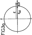
図3a及び3bに示すように、音響波の位相の変調φは、フォトダイオード12で見られる|E|2の信号の変調で反射される。
As shown in FIGS. 3 a and 3 b, the phase modulation φ of the acoustic wave is reflected by the modulation of the | E | 2 signal seen at the
図3aにおいては、位相の変調φは0(“書き出し”ステップ)に等しく、回折波DIFは信号波の音響光学成分の位相にある。結晶9内の振幅Eは最大であり、信号波の音響光学成分および回折波のそれぞれの振幅EAOおよびEdifの和に対応する。フォトダイオードで見られる信号は、強度I=|E|2に比例して、最大である。 In FIG. 3a, the phase modulation φ is equal to 0 (“write” step) and the diffracted wave DIF is in phase with the acousto-optic component of the signal wave. The amplitude E in the crystal 9 is the largest and corresponds to the sum of the acousto-optic component of the signal wave and the respective amplitudes E AO and E dif of the diffracted wave. The signal seen at the photodiode is maximal in proportion to the intensity I = | E | 2 .
図3bは、位相の変調がπ(“読み出し”ステップ)に等しい場合であり、回折波DIFは信号波の音響光学成分の逆位相にある。全体の振幅Eは、信号波の音響光学成分の振幅EAOと、回折波の振幅Edifの差に対応し、フォトダイオードで見られる信号としては最小である。 FIG. 3 b shows the case where the phase modulation is equal to π (“read” step), and the diffracted wave DIF is in antiphase with the acousto-optic component of the signal wave. The overall amplitude E corresponds to the difference between the amplitude EAO of the acousto-optic component of the signal wave and the amplitude Edif of the diffracted wave, and is the smallest signal seen at the photodiode.
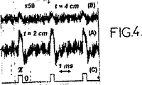
図4はオシロスコープのスクリーンを示し、信号(C)は、映し出される対象に加えられる音響波の位相の変調を表しており、1/8のデューティサイクルと305Hzの周波数を示している。信号(A)は、鳥のフィレ肉の厚さ2cmの小片である映し出される対象に対して検出された信号を表す。信号(B)は、鳥のフィレ肉の厚さ4cmの小片に対して50倍に拡大された平均の検出された信号を表す。 FIG. 4 shows an oscilloscope screen where signal (C) represents the modulation of the phase of the acoustic wave applied to the object being projected, showing a 1/8 duty cycle and a frequency of 305 Hz. Signal (A) represents the signal detected for the object being projected, which is a 2 cm thick piece of bird fillet. Signal (B) represents the average detected signal magnified 50 times for a 4 cm thick piece of bird fillet.
例えばポンプレーザー媒体等の他の構成に対しては、役割が逆になる。つまり、φ=0に対して逆位相となり、φ=πに対して信号の位相となる。 For other configurations, such as a pump laser medium, the role is reversed. That is, it becomes an antiphase with respect to φ = 0 and a signal phase with respect to φ = π.
映し出される対象1の領域5に関連する情報は、フォトダイオード12により検出される信号の同期検出により抽出することが可能である。
Information relating to the region 5 of the
“エネルギー伝達”構成においては、フォトリフラクティブ結晶9は必ずしも用いられるものではない。異なって方向付けられた面9a、9bを有する結晶を用いて、“異方性”構成を用いることも可能である。屈折率格子により回折された波及び信号波の音響光学成分は、直交偏光を有するようになる。二つの波を干渉させるために、例えば、周知の方法で1/4波長板や偏光キューブが用いられる。例えば、この構成で用いられる位相の変調により、50%のデューティサイクルで0からπ/2へのパルスの位相の変調が行われる。従って、直線的な検出が可能である。 In the “energy transfer” configuration, the photorefractive crystal 9 is not necessarily used. It is also possible to use an “anisotropic” configuration with crystals having differently oriented faces 9a, 9b. The acousto-optic component of the wave and signal wave diffracted by the refractive index grating has orthogonal polarization. In order to cause the two waves to interfere, for example, a quarter wave plate or a polarizing cube is used by a well-known method. For example, the phase modulation used in this configuration results in a pulse phase modulation from 0 to π / 2 with a 50% duty cycle. Therefore, linear detection is possible.
本実施例の装置により、従来技術の装置の場合とは異なり、フォトダイオードを用いて広範な光学的空間に亘って検出することが可能であるので、質の良い画像を得ることができる。 Unlike the device of the prior art, the device of this embodiment can detect over a wide optical space using a photodiode, so that a high-quality image can be obtained.
フォトリフラクティブ効果の周波数選択性は、屈折率格子を形成するのに必要な時間Tpと、ポンプ波PMPと信号波の搬送波成分との間の周波数の差fa=2MHzとにより特徴付けられる。Tp×fa>>1の時には、信号波の成分に関連したフォトンは屈折率格子を生成しない。 The frequency selectivity of the photorefractive effect is characterized by the time T p required to form the refractive index grating and the frequency difference f a = 2 MHz between the pump wave PMP and the carrier component of the signal wave. When T p × f a >> 1, photons associated with signal wave components do not generate a refractive index grating.
この選択性の条件は非常に幅広く実施される。本実施例においては、例えば、Tp=1〜10msとする。これは、Tp×fa=103〜104に相当する。 This selectivity condition is very widely implemented. In this embodiment, for example, T p = 1 to 10 ms. This corresponds to T p × f a = 10 3 to 10 4 .
このような装置により、従来技術の装置と比較して測定速度を上昇させることが可能となる。測定速度を上昇させることは、測定時間を減少させることを意味し、従って形成時間Tpを減少させる。ポンプ波PMPの出力を本実施例の場合と比べて増加させることにより、この形成時間は簡単に減少可能である。例えば、初期波INIの出力を増加させることにより、入射波INCの出力とポンプ波PMPの出力の両方を増加させることが可能である。ポンプ波PMPの出力の増加は、形成時間を減少させる。他方、入射波INCの出力の増加は、信号を増大させる。本実施例の場合と比べて初期波の出力を増加させることが可能であり、従って、入射波の出力が増加されるが、人体組織を取り扱うのに安全な範囲内に保持されている。ポンプ波は試料を通過しないので、ポンプ波の出力は安全性に関する問題を有さない。 Such a device makes it possible to increase the measurement speed compared to prior art devices. Increasing the measurement speed, and means to reduce the measurement time, thus reducing the forming time T p. By increasing the output of the pump wave PMP compared to the case of the present embodiment, this formation time can be easily reduced. For example, by increasing the output of the initial wave INI, it is possible to increase both the output of the incident wave INC and the output of the pump wave PMP. Increasing the output of the pump wave PMP decreases the formation time. On the other hand, an increase in the output of the incident wave INC increases the signal. Compared to the case of the present embodiment, the output of the initial wave can be increased. Therefore, the output of the incident wave is increased, but is kept within a safe range for handling human tissue. Since the pump wave does not pass through the sample, the output of the pump wave has no safety issues.
本実施例に対して、実施例の変形体を用いて下記の構成を実施することが可能である。
− 更に強力なレーザーを用いる。
− 大きなダイオード領域を有し同じ角度の開口を保持するように更に大口径のレンズ10、11、12、13を用いる。
− 例えばペルチエ冷却フォトダイオード等の更に低ノイズなフォトダイオード12を用いる。
− 更に広範な領域を有するフォトダイオードを用いる。
In contrast to the present embodiment, it is possible to implement the following configuration by using a modification of the embodiment.
-Use a more powerful laser.
Use
Use a
-Use a photodiode with a wider area.
これらの構成の全てにより、検出の信号対ノイズの比を増加可能である。 All of these configurations can increase the detection signal-to-noise ratio.
1 対象
2 圧電型変換器
3 タンク
4 水
5 領域
6 レーザー
7 スプリッティングプリズム
8a、8b 音響光学変調器
9 ダイナミックホログラフィック材料
10、11、13、14 大口径レンズ
12 フォトダイオード
15 レンズ
16 反射板
DESCRIPTION OF
Claims (22)
(b)入射波(INC)、及び前記入射波(INC)とコヒーレントなポンプ波(PMP)を発生させる段階であって、
− 光波発生装置を用いて初期光波(INI)を発生させる段階、
− 前記初期光波を第1ビーム(F1)と第2ビーム(F2)とにスプリットさせる段階、
− 第1周波数シフトにより前記第1ビームの周波数をシフトさせて前記入射波(INC)を発生させる段階、及び、
− 第2周波数シフトにより前記第2ビームの周波数をシフトさせて前記ポンプ波(PMP)を発生させる段階を備え、
前記第2周波数シフトは前記第1周波数シフトと前記音響周波数との和に略等しい、段階と、
(c)前記入射波(INC)を前記対象に加えて、前記音響波により周波数がシフトされた音響光学成分を少なくとも一つ有する信号光波(SIG)を、前記対象を通過させて前記対象の前記領域と作用させることによって発生させる段階であって、前記音響光学成分が前記ポンプ波(PMP)の周波数と同等の周波数を有する、段階と、
(d)ダイナミックホログラフィック材料(9)に前記信号波及び前記ポンプ波を加えることにより、複素屈折率格子を前記材料内に形成する段階と、
(e)前記領域内の光の強度に関連するデジタルパラメータを前記複素屈折率格子から得る段階と、を備える対象用音響光学トモグラフィイメージング方法。(A) generating the vibration of the region (5) of the object (1) by applying an acoustic wave having a predetermined acoustic frequency to the object;
(B) generating an incident wave (INC) and a pump wave (PMP) coherent with the incident wave (INC),
-Generating an initial light wave (INI) using a light wave generator;
-Splitting the initial light wave into a first beam (F1) and a second beam (F2);
-Shifting the frequency of the first beam by a first frequency shift to generate the incident wave (INC); and
-Generating the pump wave (PMP) by shifting the frequency of the second beam by a second frequency shift;
The second frequency shift is approximately equal to the sum of the first frequency shift and the acoustic frequency; and
(C) adding the incident wave (INC) to the object and passing the signal light wave (SIG) having at least one acousto-optic component shifted in frequency by the acoustic wave through the object; Generating by interacting with a region, wherein the acousto-optic component has a frequency equivalent to the frequency of the pump wave (PMP) ;
(D) forming a complex refractive index grating in the material by applying the signal wave and the pump wave to the dynamic holographic material (9);
(E) obtaining a digital parameter related to the intensity of light in the region from the complex index grating, and an acousto-optic tomography imaging method for an object.
(e1)前記複素屈折率格子に対して前記ポンプ波(PMP)を加えることにより、回折波を発生させる段階と、
(e2)前記回折波と前記信号波との間の干渉を光検出器(12)を用いて検出する段階と、を備える請求項1に記載の方法。In the step (e),
(E1) generating a diffracted wave by applying the pump wave (PMP) to the complex refractive index grating;
(E2) detecting the interference between the diffracted wave and the signal wave using a photodetector (12).
(B)前記対象に入射波(INC)を加えて、前記音響波により周波数がシフトされた音響光学成分を少なくとも一つ有する信号光波(SIG)を発生させるように設計され、且つ前記音響光学成分の周波数と同等な周波数で前記入射波とコヒーレントな光ポンプ波(PMP)を発生させるように設計された光波発生装置と、
(C)前記信号波及び前記ポンプ波を加えることにより複素屈折率格子が形成されるように適合されたダイナミックホログラフィック材料(9)と、
(D)前記複素屈折率格子から前記領域の光の強度に関連するデジタルパラメータを得るように設計された検出装置と、を備える対象用音響光学トモグラフィイメージング装置であって、
前記光波発生装置は、
初期波を発するように設計されたレーザー(6)と、
前記初期波から第1ビーム及び第2ビームを発生させるように設計されたスプリッター装置(7)と、
前記第1ビームの周波数をシフトさせて前記入射波を発生させるように設計された第1シフト装置と、
前記第2ビームの周波数をシフトさせて前記ポンプ波を発生させるように設計された第2シフト装置と、を備え、
前記第1シフト装置及び前記第2シフト装置は、前記ポンプ波が前記入射波の周波数と前記音響波の周波数の和に略等しい周波数を示すように設計されている、装置。(A) a transducer (2) designed to generate vibrations in the area (5) of the object by applying an acoustic wave having a predetermined acoustic frequency to the object (1);
(B) The acousto-optic component is designed to generate a signal light wave (SIG) having at least one acousto-optic component whose frequency is shifted by the acoustic wave by applying an incident wave (INC) to the object. An optical wave generator designed to generate an optical pump wave (PMP) coherent with the incident wave at a frequency equivalent to the frequency of
(C) a dynamic holographic material (9) adapted to form a complex refractive index grating by applying the signal wave and the pump wave;
(D) a target acousto-optic tomography imaging device comprising: a detection device designed to obtain a digital parameter related to the intensity of light in the region from the complex index grating;
The light wave generator is
A laser (6) designed to emit an initial wave;
A splitter device (7) designed to generate a first beam and a second beam from the initial wave;
A first shift device designed to shift the frequency of the first beam to generate the incident wave;
A second shift device designed to generate the pump wave by shifting the frequency of the second beam,
The first shift device and the second shift device are devices designed such that the pump wave exhibits a frequency substantially equal to the sum of the frequency of the incident wave and the frequency of the acoustic wave.
前記ダイナミックホログラフィック材料の第2面に前記ポンプ波を加えるように設計された第2光学装置(16)と、
前記ダイナミックホログラフィック材料の前記第1面に対向する第3面(9c)の画像を前記検出器(12)上に形成するように設計された第3光学装置(13、14、15)と、を備える請求項14または請求項15のいずれかに記載の装置。A first optical device (10, 11) designed to apply the signal wave to a first surface of the dynamic holographic material;
A second optical device (16) designed to apply the pump wave to a second surface of the dynamic holographic material;
A third optical device (13, 14, 15) designed to form an image of a third surface (9c) opposite the first surface of the dynamic holographic material on the detector (12); An apparatus according to claim 14 or claim 15 comprising :
Applications Claiming Priority (3)
| Application Number | Priority Date | Filing Date | Title |
|---|---|---|---|
| FR0406592 | 2004-06-17 | ||
| FR0406592A FR2871902B1 (en) | 2004-06-17 | 2004-06-17 | METHOD AND INSTALLATION OF ACOUSTO-OPTICAL IMAGING |
| PCT/FR2005/001446 WO2006005836A1 (en) | 2004-06-17 | 2005-06-10 | Method and installation for acousto-optic imaging |
Publications (2)
| Publication Number | Publication Date |
|---|---|
| JP2008502932A JP2008502932A (en) | 2008-01-31 |
| JP4828527B2 true JP4828527B2 (en) | 2011-11-30 |
Family
ID=34945992
Family Applications (1)
| Application Number | Title | Priority Date | Filing Date |
|---|---|---|---|
| JP2007515989A Expired - Fee Related JP4828527B2 (en) | 2004-06-17 | 2005-06-10 | Acousto-optic imaging method and apparatus |
Country Status (7)
| Country | Link |
|---|---|
| US (1) | US7733742B2 (en) |
| EP (1) | EP1756677B1 (en) |
| JP (1) | JP4828527B2 (en) |
| CA (1) | CA2569985C (en) |
| FR (1) | FR2871902B1 (en) |
| IL (1) | IL180008A0 (en) |
| WO (1) | WO2006005836A1 (en) |
Families Citing this family (25)
| Publication number | Priority date | Publication date | Assignee | Title |
|---|---|---|---|---|
| US8075751B2 (en) | 2008-10-16 | 2011-12-13 | Finnchem Usa, Inc. | Water chlorinator having dual functioning electrodes |
| US9057695B2 (en) * | 2009-09-24 | 2015-06-16 | Canon Kabushiki Kaisha | Apparatus and method for irradiating a scattering medium with a reconstructive wave |
| US9234841B2 (en) | 2010-01-25 | 2016-01-12 | Washington University | Optical time reversal by ultrasonic encoding in biological tissue |
| US9335605B2 (en) * | 2010-01-25 | 2016-05-10 | Washington University | Iteration of optical time reversal by ultrasonic encoding in biological tissue |
| US8817255B2 (en) | 2010-12-17 | 2014-08-26 | Canon Kabushiki Kaisha | Apparatus and method for irradiating a scattering medium |
| US8976433B2 (en) | 2010-12-17 | 2015-03-10 | Canon Kabushiki Kaisha | Apparatus and method for irradiating a scattering medium |
| US8954130B2 (en) * | 2010-12-17 | 2015-02-10 | Canon Kabushiki Kaisha | Apparatus and method for irradiating a medium |
| US8997572B2 (en) | 2011-02-11 | 2015-04-07 | Washington University | Multi-focus optical-resolution photoacoustic microscopy with ultrasonic array detection |
| US9304490B2 (en) | 2011-05-27 | 2016-04-05 | Canon Kabushiki Kaisha | Apparatus and method for irradiating a medium |
| US11020006B2 (en) | 2012-10-18 | 2021-06-01 | California Institute Of Technology | Transcranial photoacoustic/thermoacoustic tomography brain imaging informed by adjunct image data |
| US11137375B2 (en) | 2013-11-19 | 2021-10-05 | California Institute Of Technology | Systems and methods of grueneisen-relaxation photoacoustic microscopy and photoacoustic wavefront shaping |
| RU2601729C1 (en) * | 2015-09-18 | 2016-11-10 | Александр Сергеевич Мачихин | Method and device for optically transparent micro-objects spectral digital holographic images recording |
| US9906870B2 (en) * | 2016-02-15 | 2018-02-27 | Aalap Rajendra SHAH | Apparatuses and methods for sound recording, manipulation, distribution and pressure wave creation through energy transfer between photons and media particles |
| WO2017177213A1 (en) * | 2016-04-08 | 2017-10-12 | The Penn State Research Foundation | Ultrasonic/acoustic control of light waves for left-right optical reflection asymmetry |
| WO2018209046A1 (en) | 2017-05-10 | 2018-11-15 | Washington University | Snapshot photoacoustic photography using an ergodic relay |
| US10016137B1 (en) | 2017-11-22 | 2018-07-10 | Hi Llc | System and method for simultaneously detecting phase modulated optical signals |
| US10420469B2 (en) | 2017-11-22 | 2019-09-24 | Hi Llc | Optical detection system for determining neural activity in brain based on water concentration |
| US10368752B1 (en) | 2018-03-08 | 2019-08-06 | Hi Llc | Devices and methods to convert conventional imagers into lock-in cameras |
| US11206985B2 (en) | 2018-04-13 | 2021-12-28 | Hi Llc | Non-invasive optical detection systems and methods in highly scattering medium |
| US11857316B2 (en) | 2018-05-07 | 2024-01-02 | Hi Llc | Non-invasive optical detection system and method |
| CN110635340B (en) * | 2018-06-22 | 2022-01-25 | 成都晶特激光技术有限公司 | Novel adjustable miniature human eye safety solid laser |
| WO2020037082A1 (en) | 2018-08-14 | 2020-02-20 | California Institute Of Technology | Multifocal photoacoustic microscopy through an ergodic relay |
| EP3847453A4 (en) | 2018-09-04 | 2022-06-22 | California Institute of Technology | Enhanced-resolution infrared photoacoustic microscopy and spectroscopy |
| US11369280B2 (en) | 2019-03-01 | 2022-06-28 | California Institute Of Technology | Velocity-matched ultrasonic tagging in photoacoustic flowgraphy |
| CN110133879B (en) * | 2019-04-25 | 2022-12-09 | 福建师范大学 | Device and method for improving ultrasonic modulation light imaging depth |
Citations (2)
| Publication number | Priority date | Publication date | Assignee | Title |
|---|---|---|---|---|
| JP2000089648A (en) * | 1998-09-10 | 2000-03-31 | Sony Corp | Hologram recording and reproducing device and hologram recording medium |
| US6175411B1 (en) * | 1998-02-25 | 2001-01-16 | Bechtel Bwxt Idaho, Llc | Apparatus and method for measuring and imaging traveling waves |
Family Cites Families (6)
| Publication number | Priority date | Publication date | Assignee | Title |
|---|---|---|---|---|
| US3474402A (en) * | 1968-05-06 | 1969-10-21 | Us Navy | Variable focus electroacoustic transducer |
| FR2395534A1 (en) * | 1977-06-24 | 1979-01-19 | Thomson Csf | ACOUSTO-OPTICAL IMAGING DEVICE WITH REAL-TIME COHERENT HOLOGRAPHIC DETECTION |
| US6175416B1 (en) * | 1996-08-06 | 2001-01-16 | Brown University Research Foundation | Optical stress generator and detector |
| US6678211B2 (en) * | 1998-04-03 | 2004-01-13 | The Board Of Trustees Of The Leland Stanford Junior University | Amplified tree structure technology for fiber optic sensor arrays |
| US6401540B1 (en) * | 2000-02-29 | 2002-06-11 | Bechtel Bwxt Idaho, Llc | Method and apparatus for detecting internal structures of bulk objects using acoustic imaging |
| US7624640B2 (en) * | 2005-06-03 | 2009-12-01 | Brown University | Opto-acoustic methods and apparatus for performing high resolution acoustic imaging and other sample probing and modification operations |
-
2004
- 2004-06-17 FR FR0406592A patent/FR2871902B1/en not_active Expired - Fee Related
-
2005
- 2005-06-10 CA CA2569985A patent/CA2569985C/en not_active Expired - Fee Related
- 2005-06-10 WO PCT/FR2005/001446 patent/WO2006005836A1/en not_active Application Discontinuation
- 2005-06-10 JP JP2007515989A patent/JP4828527B2/en not_active Expired - Fee Related
- 2005-06-10 EP EP05777176.8A patent/EP1756677B1/en not_active Not-in-force
- 2005-06-10 US US11/570,252 patent/US7733742B2/en not_active Expired - Fee Related
-
2006
- 2006-12-12 IL IL180008A patent/IL180008A0/en not_active IP Right Cessation
Patent Citations (2)
| Publication number | Priority date | Publication date | Assignee | Title |
|---|---|---|---|---|
| US6175411B1 (en) * | 1998-02-25 | 2001-01-16 | Bechtel Bwxt Idaho, Llc | Apparatus and method for measuring and imaging traveling waves |
| JP2000089648A (en) * | 1998-09-10 | 2000-03-31 | Sony Corp | Hologram recording and reproducing device and hologram recording medium |
Also Published As
| Publication number | Publication date |
|---|---|
| US7733742B2 (en) | 2010-06-08 |
| US20080037367A1 (en) | 2008-02-14 |
| FR2871902A1 (en) | 2005-12-23 |
| CA2569985A1 (en) | 2006-01-19 |
| IL180008A0 (en) | 2007-05-15 |
| CA2569985C (en) | 2014-08-26 |
| EP1756677B1 (en) | 2018-04-04 |
| EP1756677A1 (en) | 2007-02-28 |
| FR2871902B1 (en) | 2006-09-22 |
| WO2006005836A1 (en) | 2006-01-19 |
| JP2008502932A (en) | 2008-01-31 |
Similar Documents
| Publication | Publication Date | Title |
|---|---|---|
| JP4828527B2 (en) | Acousto-optic imaging method and apparatus | |
| JP5627797B2 (en) | Apparatus and method for irradiating a medium | |
| JP6357263B2 (en) | System for irradiating a medium | |
| US7652773B2 (en) | Enhanced detection of acousto-photonic emissions in optically turbid media using a photo-refractive crystal-based detection system | |
| US9304490B2 (en) | Apparatus and method for irradiating a medium | |
| US20120307250A1 (en) | Optical time reversal by ultrasonic encoding in biological tissue | |
| JP4679507B2 (en) | Acoustooptic imaging method and acoustooptic imaging apparatus | |
| Sui et al. | Imaging in diffuse media with pulsed-ultrasound-modulated light and the photorefractive effect | |
| US5684588A (en) | Homodyne and hetrodyne imaging in a light scattering medium | |
| KR100584010B1 (en) | The laser ultrasonic apparatus and method using multi-photosensors | |
| Imano | Optical observation method for ultrasonic field using the shadowgraph introducing pulse inversion averaging | |
| CN115201115A (en) | Photoacoustic imaging device and method based on structured light detection | |
| EP3761857B1 (en) | Acousto-optic imaging methods and systems | |
| WO2014196150A1 (en) | Acousto-optic image pickup device | |
| Nowak et al. | Plane wave acousto-optic imaging in reflection mode geometry | |
| Metherell et al. | Temporal reference acoustical holography | |
| KR102374163B1 (en) | Schlieren-style imaging system for acoustic field amplitude analysis and method of analyzing the same | |
| JP2018179529A (en) | Device, method, and program for acquiring response characteristics | |
| Shu et al. | One-dimensional optoacoustic receive array employing parallel detection and video-rate acquisition | |
| JPS6297245A (en) | Imaging system | |
| Goloni et al. | Optical measurements of vibration waves: Analysis of point-scanning and full-field interferometric methods | |
| Daoudi et al. | Discrimination of shear mechanical and optical contrasts in tissue phantoms by use of opto-elastography | |
| Massey | Practical applications of the optical-heterodyne ultrasonic image-converter | |
| Ramaz et al. | Ultrasonically Modulated Optical Imaging | |
| Bossy et al. | Combination of ultrasound and acousto-optical imaging using a pulsed-ultrasound scanner |
Legal Events
| Date | Code | Title | Description |
|---|---|---|---|
| A621 | Written request for application examination |
Free format text: JAPANESE INTERMEDIATE CODE: A621 Effective date: 20080418 |
|
| A131 | Notification of reasons for refusal |
Free format text: JAPANESE INTERMEDIATE CODE: A131 Effective date: 20101124 |
|
| A521 | Request for written amendment filed |
Free format text: JAPANESE INTERMEDIATE CODE: A523 Effective date: 20110224 |
|
| A131 | Notification of reasons for refusal |
Free format text: JAPANESE INTERMEDIATE CODE: A131 Effective date: 20110426 |
|
| A521 | Request for written amendment filed |
Free format text: JAPANESE INTERMEDIATE CODE: A523 Effective date: 20110720 |
|
| TRDD | Decision of grant or rejection written | ||
| A01 | Written decision to grant a patent or to grant a registration (utility model) |
Free format text: JAPANESE INTERMEDIATE CODE: A01 Effective date: 20110816 |
|
| A01 | Written decision to grant a patent or to grant a registration (utility model) |
Free format text: JAPANESE INTERMEDIATE CODE: A01 |
|
| A61 | First payment of annual fees (during grant procedure) |
Free format text: JAPANESE INTERMEDIATE CODE: A61 Effective date: 20110914 |
|
| FPAY | Renewal fee payment (event date is renewal date of database) |
Free format text: PAYMENT UNTIL: 20140922 Year of fee payment: 3 |
|
| R150 | Certificate of patent or registration of utility model |
Free format text: JAPANESE INTERMEDIATE CODE: R150 |
|
| R250 | Receipt of annual fees |
Free format text: JAPANESE INTERMEDIATE CODE: R250 |
|
| R250 | Receipt of annual fees |
Free format text: JAPANESE INTERMEDIATE CODE: R250 |
|
| R250 | Receipt of annual fees |
Free format text: JAPANESE INTERMEDIATE CODE: R250 |
|
| R250 | Receipt of annual fees |
Free format text: JAPANESE INTERMEDIATE CODE: R250 |
|
| LAPS | Cancellation because of no payment of annual fees |