JP4823751B2 - Drawing point data acquisition method and apparatus, and drawing method and apparatus - Google Patents
Drawing point data acquisition method and apparatus, and drawing method and apparatus Download PDFInfo
- Publication number
- JP4823751B2 JP4823751B2 JP2006117384A JP2006117384A JP4823751B2 JP 4823751 B2 JP4823751 B2 JP 4823751B2 JP 2006117384 A JP2006117384 A JP 2006117384A JP 2006117384 A JP2006117384 A JP 2006117384A JP 4823751 B2 JP4823751 B2 JP 4823751B2
- Authority
- JP
- Japan
- Prior art keywords
- point data
- drawing point
- image
- data
- target
- Prior art date
- Legal status (The legal status is an assumption and is not a legal conclusion. Google has not performed a legal analysis and makes no representation as to the accuracy of the status listed.)
- Expired - Fee Related
Links
Images


Landscapes
- Exposure And Positioning Against Photoresist Photosensitive Materials (AREA)
Description
本発明は、描画点データに基づいて描画点を形成する描画点形成領域を、描画対象に対して相対的に移動させるとともに、その移動に応じて描画点を順次形成して画像を描画する際に用いられる描画点データの取得方法および装置並びにその描画点データ取得方法および装置により取得された描画点データを用いて上記描画を行う描画方法および装置に関するものである。 The present invention moves a drawing point formation region for forming a drawing point based on drawing point data relative to a drawing target and draws an image by sequentially forming drawing points according to the movement. The present invention relates to a drawing point data acquisition method and apparatus used in the above, and a drawing method and apparatus for performing the drawing using drawing point data acquired by the drawing point data acquisition method and apparatus.
従来、プリント配線板やフラットパネルディスプレイの基板に所定のパターンを記録する装置として、フォトリソグラフの技術を利用した露光装置が種々提案されている。 Conventionally, various exposure apparatuses using a photolithographic technique have been proposed as apparatuses for recording a predetermined pattern on a printed wiring board or a flat panel display substrate.
上記のような露光装置としては、たとえば、フォトレジストが塗布された基板上に光ビームを主走査および副走査方向に走査させるとともに、その光ビームを、配線パターンを表す画像データに基づいて変調することにより配線パターンを形成する露光装置が提案されている。 As an exposure apparatus as described above, for example, a light beam is scanned in a main scanning direction and a sub scanning direction on a substrate coated with a photoresist, and the light beam is modulated based on image data representing a wiring pattern. Thus, there has been proposed an exposure apparatus for forming a wiring pattern.
上記のような露光装置として、たとえば、デジタル・マイクロミラー・デバイス(以下、DMDという)等の空間光変調素子を利用し、画像データに応じて空間光変調素子により光ビームを変調して露光を行う露光装置が種々提案されている。 As the exposure apparatus as described above, for example, a spatial light modulator such as a digital micromirror device (hereinafter referred to as DMD) is used, and exposure is performed by modulating a light beam by the spatial light modulator according to image data. Various exposure apparatuses have been proposed.
そして、上記のようなDMDを用いた露光装置としては、たとえば、DMDを露光面に対して相対的に移動させるとともに、その移動に応じてDMDの多数のマイクロミラーに対応した多数の描画点データを入力し、DMDのマイクロミラーに対応した描画点群を時系列に順次形成することにより所望の画像を露光面に形成する露光装置が提案されている(たとえば特許文献1参照)。 As an exposure apparatus using the DMD as described above, for example, the DMD is moved relative to the exposure surface, and a large number of drawing point data corresponding to a large number of micromirrors of the DMD according to the movement. An exposure apparatus is proposed that forms a desired image on an exposure surface by sequentially forming drawing point groups corresponding to DMD micromirrors in a time series (see, for example, Patent Document 1).
ここで、上記のような露光装置を用いて露光を行う際には、露光面に対するDMDの各位置に対応した描画点データが、上記移動にともなって順次DMDに入力されるが、上記描画点データは、たとえば、CADステーションやCAM(Computer Aided Manufacturing)ステーション等を有するデータ作成装置において作成されたベクトル形式の画像データをラスター形式の画像データに変換し、そのラスター形式の画像データから露光面に対するDMDの各位置に応じた画素データを読み出すことによって取得される(たとえば特許文献2および特許文献3参照)。
Here, when performing exposure using the exposure apparatus as described above, drawing point data corresponding to each position of the DMD with respect to the exposure surface is sequentially input to the DMD with the movement. As the data, for example, vector format image data created in a data creation apparatus having a CAD station, a CAM (Computer Aided Manufacturing) station, or the like is converted into raster format image data, and the raster format image data is applied to the exposure surface. It is obtained by reading out pixel data corresponding to each position of the DMD (see, for example,
しかしながら、上記のようにして描画点データを取得する際、たとえば、露光対象である基板に変形などが生じている場合には、その基板の変形に応じてラスター形式の画像データから読み出す画素位置が調整されて描画点データが取得されるが、ラスター形式の画像データの解像度はベクトル形式の画像データの解像度よりも低いため、線幅などの精度が低くなってしまう場合がある。また、配線パターンに斜めの線が存在する場合には、その斜めの線にジャギが発生してしまう場合などがあり、露光精度が劣化してしまう。 However, when the drawing point data is acquired as described above, for example, when the substrate to be exposed is deformed, the pixel position to be read from the raster image data is changed according to the deformation of the substrate. The drawing point data is acquired after adjustment, but the resolution of the raster format image data is lower than the resolution of the vector format image data, and thus the accuracy such as the line width may be lowered. In addition, when there is an oblique line in the wiring pattern, there is a case where a jaggy is generated in the oblique line, and the exposure accuracy is deteriorated.
また、上記のような問題を回避するため、ラスター形式の画像データの解像度を上げることも考えられるが、ラスター形式の画像データの解像度を上げるとそのデータ量が膨大になってしまうため、画像データにおける読み出し画素位置の演算に時間がかかったり、画像データへのアクセス回数も増大したりして処理速度の低下を招くおそれがある。また画像データを記憶するメモリの容量を増やす必要が生じコストアップを招くおそれもある。 In order to avoid the above problems, it may be possible to increase the resolution of raster format image data. However, if the resolution of raster format image data is increased, the amount of data becomes enormous. There is a possibility that the calculation of the read pixel position takes time, and the number of accesses to the image data increases, leading to a decrease in processing speed. Further, it is necessary to increase the capacity of the memory for storing the image data, which may increase the cost.
本発明は、上記事情に鑑み、上記のような描画点データを取得する方法において、上記のような処理速度の低下およびコストアップを招くことなく、描画精度の向上を図ることができる描画点データ取得方法および装置並びにその描画点データ取得方法および装置により取得された描画点データを用いて描画を行う描画方法および装置を提供することを目的とするものである。 In view of the above circumstances, the present invention provides a drawing point data that can improve the drawing accuracy without reducing the processing speed and increasing the cost in the method for obtaining the drawing point data as described above. It is an object of the present invention to provide an acquisition method and apparatus, and a drawing method and apparatus that perform drawing using drawing point data acquired by the drawing point data acquisition method and apparatus.
本発明の第1の描画点データ取得方法は、描画点データに基づいて描画点を描画対象上に形成して描画対象上に画像を描画する際に用いられる描画点データを取得する描画点データ取得方法において、画像の元のベクトル形式の画像データを取得するとともに、描画対象上における描画点を形成すべき位置に対応する画像データ上の位置座標を取得し、ベクトル形式の画像データと上記位置座標とに基づいて描画点の描画点データを取得することを特徴とする。 The first drawing point data acquisition method of the present invention is a drawing point data for forming drawing points on a drawing target based on the drawing point data and acquiring drawing point data used when drawing an image on the drawing target. In the acquisition method, the image data in the original vector format of the image is acquired, and the position coordinates on the image data corresponding to the position where the drawing point on the drawing target is to be formed are acquired. Drawing point data of a drawing point is acquired based on the coordinates.
また、上記本発明の第1の描画点データ取得方法においては、画像データに基づいて決定される画像領域と位置座標とを重ね合わせ、上記位置座標が属する画像領域の画像データに基づいて描画点データを取得するようにすることができる。 In the first drawing point data acquisition method of the present invention, the image area determined based on the image data and the position coordinate are overlapped, and the drawing point is determined based on the image data of the image area to which the position coordinate belongs. Data can be acquired.
また、描画点データに基づいて描画点を形成する描画点形成領域を、描画対象に対して相対的に移動させるとともに、その移動に応じて描画点を描画対象上に順次形成して描画対象上に画像を描画する際に用いられる描画点データを取得する描画点データ取得方法であって、位置座標を、描画対象上の所定位置における描画点形成領域に対応するものとすることができる。 In addition, the drawing point forming area for forming the drawing point based on the drawing point data is moved relative to the drawing target, and the drawing point is sequentially formed on the drawing target in accordance with the movement. In the drawing point data acquisition method for acquiring drawing point data used when drawing an image, the position coordinates can correspond to a drawing point formation region at a predetermined position on the drawing target.
また、画像データに基づいて決定される画像領域と上記位置座標を含む線とを重ね合わせ、上記線が重なる画像領域の画像データに基づいて描画点データを取得するようにすることができる。 また、画像データと線との交点の位置に基づいて描画点データを取得するようにすることができる。 Further, it is possible to superimpose an image area determined based on image data and a line including the position coordinates, and to obtain drawing point data based on image data of an image area where the line overlaps. Further, the drawing point data can be acquired based on the position of the intersection between the image data and the line.
また、画像データに表されまたは画像データから求められる画像の輪郭と、線との交点を示す交点配置情報を取得し、その交点配置情報に基づいて描画点データを取得するようにすることができる。 Further, it is possible to acquire intersection arrangement information indicating the intersection of the contour of the image represented in the image data or obtained from the image data and the line, and acquire drawing point data based on the intersection arrangement information. .
また、線を、複数の描画点に対応する複数の位置座標を結ぶものとすることができる。 In addition, a line can be connected to a plurality of position coordinates corresponding to a plurality of drawing points.
また、線を、時系列に並ぶ複数の描画点に対応する複数の位置座標を結ぶものとすることができる。 In addition, a line can be connected to a plurality of position coordinates corresponding to a plurality of drawing points arranged in time series.
また、描画点データに基づいて描画点を形成する描画点形成領域を、描画対象に対して相対的に移動させるとともに、その移動に応じて描画点を描画対象上に順次形成して描画対象上に画像を描画する際に用いられる描画点データを取得する描画点データ取得方法であって、線を、時系列に並ぶ複数の描画点に対応する複数の位置座標を結ぶものとすることができる。 In addition, the drawing point forming area for forming the drawing point based on the drawing point data is moved relative to the drawing target, and the drawing point is sequentially formed on the drawing target in accordance with the movement. A drawing point data acquisition method for acquiring drawing point data used when drawing an image on a line, wherein a line can be connected to a plurality of position coordinates corresponding to a plurality of drawing points arranged in time series. .
また、描画点データに基づいて描画点を形成する描画点形成領域を、描画対象に対して相対的に移動させるとともに、その移動に応じて描画点を描画対象上に順次形成して描画対象上に画像を描画する際に用いられる描画点データを取得する描画点データ取得方法であって、線を、描画対象上におけるまたは描画対象上の画像空間における描画点形成領域の描画軌跡に対応するものとすることができる。 In addition, the drawing point forming area for forming the drawing point based on the drawing point data is moved relative to the drawing target, and the drawing point is sequentially formed on the drawing target in accordance with the movement. A drawing point data acquisition method for acquiring drawing point data used when drawing an image on a line, wherein a line corresponds to a drawing locus of a drawing point formation area on the drawing target or in the image space on the drawing target It can be.
また、描画点データに基づいて描画点を形成する描画点形成領域を複数有する描画点形成領域群を、描画対象に対して相対的に移動させるとともに、その移動に応じて描画点形成領域群に対応する描画点群を描画対象上に順次形成して描画対象上に画像を描画する際に用いられる描画点データを取得する描画点データ取得方法であって、線を、描画対象上の所定位置における描画点形成領域群の少なくとも一部の描画点形成領域を結ぶ線に対応するものとすることができる。 In addition, the drawing point forming region group having a plurality of drawing point forming regions for forming drawing points based on the drawing point data is moved relative to the drawing target, and the drawing point forming region group is moved according to the movement. A drawing point data acquisition method for acquiring drawing point data used when a corresponding drawing point group is sequentially formed on a drawing target and an image is drawn on the drawing target. Can correspond to a line connecting at least some of the drawing point formation regions of the drawing point formation region group.
また、線にサンプリングピッチを付随させるようにすることができる。 Further, the sampling pitch can be attached to the line.
また、画像データに基づいて決定される画像領域と上記位置座標を含む所定領域とを重ね合わせ、所定領域が重なる画像領域の画像データに基づいて描画点データを取得するようにすることができる。 Further, it is possible to superimpose an image area determined based on image data and a predetermined area including the position coordinates so as to acquire drawing point data based on image data of an image area where the predetermined area overlaps.
また、描画点データに基づいて描画点を形成する描画点形成領域を複数有する描画点形成領域群を、描画対象に対して相対的に移動させるとともに、その移動に応じて描画点形成領域群に対応する描画点群を描画対象上に順次形成して描画対象上に画像を描画する際に用いられる描画点データを取得する描画点データ取得方法であって、所定領域を、描画対象上の所定位置における描画点形成領域群の少なくとも一部の領域に対応するものとすることができる。 In addition, the drawing point forming region group having a plurality of drawing point forming regions for forming drawing points based on the drawing point data is moved relative to the drawing target, and the drawing point forming region group is moved according to the movement. A drawing point data acquisition method for acquiring drawing point data used when a corresponding drawing point group is sequentially formed on a drawing target and an image is drawn on the drawing target. It may correspond to at least a part of the drawing point formation region group at the position.
本発明の第2の描画点データ取得方法は、描画点データに基づいて描画点を形成する描画点形成領域を、描画対象に対して相対的に移動させるとともに、その移動に応じて描画点を描画対象上に順次形成して描画対象上に画像を描画する際に用いられる描画点データを取得する描画点データ取得方法において、画像の元のベクトル形式の画像データを取得するとともに、画像の描画のための描画対象上におけるまたは描画対象上の画像空間における描画点形成領域の描画軌跡の情報を取得し、画像データにより表わされまたは画像データから求められる画像の輪郭と描画軌跡情報に対応する画像データ上における描画点データ軌跡との交点の配置を示す交点配置情報を取得し、交点配置情報に基づいて描画点データ軌跡に対応した描画点データを取得することを特徴とする。 In the second drawing point data acquisition method of the present invention, the drawing point forming area for forming the drawing point based on the drawing point data is moved relative to the drawing target, and the drawing point is changed according to the movement. In a drawing point data acquisition method for acquiring drawing point data that is sequentially formed on a drawing target and used for drawing an image on the drawing target, the original vector format image data of the image is acquired and the image is drawn Information on the drawing trajectory of the drawing point formation area on the drawing object for the image or in the image space on the drawing object, and corresponding to the contour and drawing trajectory information of the image represented by or obtained from the image data Intersection location information indicating the location of the intersection with the drawing point data locus on the image data is acquired, and the drawing point data corresponding to the drawing point data locus is obtained based on the intersection location information. The and acquiring.
また、上記本発明の第2の描画点データ取得方法において、描画点データ軌跡を交点配置情報により示される交点により区切って部分描画点データ軌跡とし、部分描画点データ軌跡に、その部分描画点データ軌跡の並ぶ順に2値化データを交互に割り当て、部分描画点データ軌跡毎に割り当てられた2値化データを、移動の方向に対応する画像データ上の走査方向について所定間隔でサンプリングして描画点データ軌跡に対応した描画点データを取得するようにすることができる。 In the second drawing point data acquisition method of the present invention, the drawing point data trajectory is divided by the intersection indicated by the intersection arrangement information as a partial drawing point data trajectory, and the partial drawing point data trajectory includes the partial drawing point data trajectory. The binarized data is alternately assigned in the order in which the trajectories are arranged, and the binarized data assigned to each partial drawing point data trajectory is sampled at predetermined intervals in the scanning direction on the image data corresponding to the direction of movement. Drawing point data corresponding to the data locus can be acquired.
また、交点配置情報の上記移動の方向に対応する画像データ上の走査方向の座標値を取得し、その取得した座標値を、画像データ上の走査方向の所定間隔の値でそれぞれ除算して量子化値を求め、画像データ上の走査方向に隣接する量子化値の差を求め、その差をランレングスデータとして取得し、その取得されたランレングスデータをデコードして描画点データ軌跡に対応した描画点データを取得するようにすることができる。 Further, a coordinate value in the scanning direction on the image data corresponding to the direction of the movement of the intersection arrangement information is acquired, and the acquired coordinate value is divided by a predetermined interval value in the scanning direction on the image data to quantize. A quantization value is obtained, a difference between quantization values adjacent to each other in the scanning direction on the image data is obtained, the difference is obtained as run length data, and the obtained run length data is decoded to correspond to a drawing point data locus. Drawing point data can be acquired.
また、予め設定された描画対象の所定相対移動速度に対する画像の描画の際の描画対象の実移動速度の変動を示す速度変動情報を取得し、その取得した速度変動情報に基づいて、描画対象の実移動速度が相対的に遅い描画対象上の描画領域ほど描画点データの数が多くなるように上記所定間隔を変化させて描画点データを取得するようにすることができる。 Also, speed fluctuation information indicating fluctuations in the actual movement speed of the drawing target at the time of drawing the image with respect to a predetermined relative movement speed of the drawing target set in advance is acquired, and based on the acquired speed fluctuation information, the drawing target The drawing point data can be acquired by changing the predetermined interval so that the number of the drawing point data increases in the drawing region on the drawing target whose actual moving speed is relatively slow.
また、描画対象上の所定位置に予め設けられた複数の基準マークを検出してその基準マークの位置を示す検出位置情報を取得し、その取得した検出位置情報に基づいて描画軌跡情報を取得するようにすることができる。 Further, a plurality of reference marks provided in advance at predetermined positions on the drawing target are detected, detection position information indicating the positions of the reference marks is acquired, and drawing trajectory information is acquired based on the acquired detection position information. Can be.
また、予め設定された描画対象の所定相対移動方向に対する画像の描画の際の描画対象の実移動方向のずれ情報を取得し、その取得したずれ情報に基づいて描画軌跡情報を取得するようにすることができる。 Also, deviation information about the actual movement direction of the drawing target when drawing an image with respect to a predetermined relative movement direction of the drawing target set in advance is acquired, and drawing trajectory information is acquired based on the acquired deviation information. be able to.
また、予め設定された描画対象の所定相対移動方向に対する画像の描画の際の描画対象の実移動方向のずれ情報を取得し、その取得したずれ情報および上記検出位置情報に基づいて描画軌跡情報を取得するようにすることができる。 Also, deviation information of the actual movement direction of the drawing target when drawing an image with respect to a predetermined relative movement direction of the drawing target set in advance is acquired, and drawing trajectory information is obtained based on the acquired deviation information and the detected position information. Can be acquired.
本発明の第1の描画方法は、描画点データに基づいて描画点を描画対象上に形成して描画対象上に画像を描画する描画方法において、画像の元のベクトル形式の画像データを取得するとともに、描画対象上における描画点を形成すべき位置に対応する画像データ上の位置座標を取得し、ベクトル形式の画像データと上記位置座標とに基づいて描画点の描画点データを取得し、その取得した描画点データに基づいて描画点を描画対象上に形成することを特徴とする。 A first drawing method of the present invention is a drawing method in which drawing points are formed on a drawing target based on the drawing point data and an image is drawn on the drawing target, and image data in the original vector format of the image is acquired. A position coordinate on the image data corresponding to a position where a drawing point on the drawing target should be formed is acquired, and drawing point data of the drawing point is acquired based on the image data in the vector format and the position coordinate. A drawing point is formed on a drawing target based on the acquired drawing point data.
また、上記本発明の第1の描画方法においては、画像データに基づいて決定される画像領域と上記位置座標とを重ね合わせ、位置座標が属する画像領域の画像データに基づいて描画点データを取得するようにすることができる。 In the first drawing method of the present invention, the image area determined based on the image data and the position coordinates are overlapped, and the drawing point data is obtained based on the image data of the image area to which the position coordinates belong. To be able to.
また、描画点データに基づいて描画点を形成する描画点形成領域を、描画対象に対して相対的に移動させるとともに、その移動に応じて描画点を描画対象上に順次形成して描画対象上に画像を描画する描画方法であって、上記位置座標を、描画対象上の所定位置における描画点形成領域に対応するものとすることができる。 In addition, the drawing point forming area for forming the drawing point based on the drawing point data is moved relative to the drawing target, and the drawing point is sequentially formed on the drawing target in accordance with the movement. In the drawing method of drawing an image, the position coordinates may correspond to a drawing point formation region at a predetermined position on the drawing target.
また、画像データに基づいて決定される画像領域と上記位置座標を含む線とを重ね合わせ、上記線が重なる画像領域の画像データに基づいて描画点データを取得するようにすることができる。 Further, it is possible to superimpose an image area determined based on image data and a line including the position coordinates, and to obtain drawing point data based on image data of an image area where the line overlaps.
また、画像データと線との交点の位置に基づいて描画点データを取得するようにすることができる。 Further, the drawing point data can be acquired based on the position of the intersection between the image data and the line.
また、画像データに表されまたは画像データから求められる画像の輪郭と、線との交点を示す交点配置情報を取得し、その交点配置情報に基づいて描画点データを取得するようにすることができる。 Further, it is possible to acquire intersection arrangement information indicating the intersection of the contour of the image represented in the image data or obtained from the image data and the line, and acquire drawing point data based on the intersection arrangement information. .
また、線を、複数の描画点に対応する複数の位置座標を結ぶものとすることができる。 In addition, a line can be connected to a plurality of position coordinates corresponding to a plurality of drawing points.
また、線を、時系列に並ぶ複数の描画点に対応する複数の位置座標を結ぶものとすることができる。 In addition, a line can be connected to a plurality of position coordinates corresponding to a plurality of drawing points arranged in time series.
また、描画点データに基づいて描画点を形成する描画点形成領域を、描画対象に対して相対的に移動させるとともに、その移動に応じて描画点を描画対象上に順次形成して描画対象上に画像を描画する描画方法であって、線を、時系列に並ぶ複数の描画点に対応する複数の位置座標を結ぶものとすることができる。 In addition, the drawing point forming area for forming the drawing point based on the drawing point data is moved relative to the drawing target, and the drawing point is sequentially formed on the drawing target in accordance with the movement. In this drawing method, a line can be connected to a plurality of position coordinates corresponding to a plurality of drawing points arranged in time series.
また、描画点データに基づいて描画点を形成する描画点形成領域を、描画対象に対して相対的に移動させるとともに、その移動に応じて描画点を描画対象上に順次形成して描画対象上に画像を描画する描画方法であって、線を、描画対象上におけるまたは描画対象上の画像空間における描画点形成領域の描画軌跡に対応するものとすることができる。 In addition, the drawing point forming area for forming the drawing point based on the drawing point data is moved relative to the drawing target, and the drawing point is sequentially formed on the drawing target in accordance with the movement. In this drawing method, the line can correspond to the drawing locus of the drawing point formation region on the drawing target or in the image space on the drawing target.
また、描画点データに基づいて描画点を形成する描画点形成領域を複数有する描画点形成領域群を、描画対象に対して相対的に移動させるとともに、その移動に応じて描画点形成領域群に対応する描画点群を描画対象上に順次形成して描画対象上に画像を描画する描画方法であって、線を、描画対象上の所定位置における描画点形成領域群の少なくとも一部の描画点形成領域を結ぶ線に対応するものとすることができる。 In addition, the drawing point forming region group having a plurality of drawing point forming regions for forming drawing points based on the drawing point data is moved relative to the drawing target, and the drawing point forming region group is moved according to the movement. A drawing method for sequentially forming corresponding drawing point groups on a drawing target and drawing an image on the drawing target, wherein a line is drawn at least in a part of the drawing point forming region group at a predetermined position on the drawing target It can correspond to a line connecting the formation regions.
また、線にサンプリングピッチの情報を付随させるようにすることができる。 In addition, information on the sampling pitch can be attached to the line.
また、画像データに基づいて決定される画像領域と上記位置座標を含む所定領域とを重ね合わせ、上記所定領域が重なる画像領域の画像データに基づいて描画点データを取得するようにすることができる。 Further, it is possible to superimpose an image area determined based on image data and a predetermined area including the position coordinates so as to acquire drawing point data based on image data of an image area where the predetermined area overlaps. .
また、描画点データに基づいて描画点を形成する描画点形成領域を複数有する描画点形成領域群を、描画対象に対して相対的に移動させるとともに、その移動に応じて描画点形成領域群に対応する描画点群を描画対象上に順次形成して描画対象上に画像を描画する描画方法であって、上記所定領域を、描画対象上の所定位置における描画点形成領域群の少なくとも一部の領域に対応するものとすることができる。 In addition, the drawing point forming region group having a plurality of drawing point forming regions for forming drawing points based on the drawing point data is moved relative to the drawing target, and the drawing point forming region group is moved according to the movement. A drawing method for sequentially forming corresponding drawing point groups on a drawing target and drawing an image on the drawing target, wherein the predetermined area is at least a part of the drawing point forming area group at a predetermined position on the drawing target. It can correspond to a region.
本発明の第2の描画方法は、描画点データに基づいて描画点を形成する描画点形成領域を、描画対象に対して相対的に移動させるとともに、その移動に応じて描画点を描画対象上に順次形成して描画対象上に画像を描画する描画方法において、画像の元のベクトル形式の画像データを取得するとともに、画像の描画のための描画対象上におけるまたは描画対象上の画像空間上における描画点形成領域の描画軌跡の情報を取得し、画像データにより表わされまたは画像データから求められる画像の輪郭と描画軌跡情報に対応する画像データ上における描画点データ軌跡との交点の配置を示す交点配置情報を取得し、交点配置情報に基づいて描画点データ軌跡に対応した描画点データを取得し、その取得した描画点データに基づいて描画点形成領域によって描画点を描画対象上に形成することを特徴とする。 According to the second drawing method of the present invention, the drawing point forming area for forming the drawing point based on the drawing point data is moved relative to the drawing target, and the drawing point is moved on the drawing target according to the movement. In the drawing method of sequentially forming the images on the drawing target and acquiring the image data in the original vector format, the image data is drawn on the drawing target for drawing the image or in the image space on the drawing target. The drawing locus information of the drawing point formation area is acquired, and the arrangement of the intersection of the image contour represented by the image data or obtained from the image data and the drawing point data locus on the image data corresponding to the drawing locus information is shown. Acquire intersection point arrangement information, acquire drawing point data corresponding to the drawing point data locus based on the intersection arrangement information, and draw point formation area based on the acquired drawing point data. And forming a drawing points on the drawing object by.
また、上記本発明の第2の描画方法においては、描画点データ軌跡を交点配置情報により示される交点により区切って部分描画点データ軌跡とし、部分描画点データ軌跡に、その部分描画点データ軌跡の並ぶ順に2値化データを交互に割り当て、その部分描画点データ軌跡毎に割り当てられた2値化データを、上記移動の方向に対応する画像データ上の走査方向について所定間隔でサンプリングして描画点データ軌跡に対応した描画点データを取得するようにすることができる。 In the second drawing method of the present invention, the drawing point data trajectory is divided by the intersection indicated by the intersection arrangement information as a partial drawing point data trajectory, and the partial drawing point data trajectory includes the partial drawing point data trajectory. The binarized data is alternately assigned in the order of arrangement, and the binarized data assigned to each partial drawing point data locus is sampled at predetermined intervals in the scanning direction on the image data corresponding to the moving direction. Drawing point data corresponding to the data locus can be acquired.
また、交点配置情報の上記移動の方向に対応する画像データ上の走査方向の座標値を取得し、その取得した座標値を、画像データ上の走査方向の所定間隔の値でそれぞれ除算して量子化値を求め、画像データ上の走査方向に隣接する量子化値の差を求め、その差をランレングスデータとして取得し、その取得されたランレングスデータをデコードして描画点データ軌跡に対応した描画点データを取得するようにすることができる。 Further, a coordinate value in the scanning direction on the image data corresponding to the direction of the movement of the intersection arrangement information is acquired, and the acquired coordinate value is divided by a predetermined interval value in the scanning direction on the image data to quantize. A quantization value is obtained, a difference between quantization values adjacent to each other in the scanning direction on the image data is obtained, the difference is obtained as run length data, and the obtained run length data is decoded to correspond to a drawing point data locus. Drawing point data can be acquired.
また、予め設定された描画対象の所定相対移動速度に対する画像の描画の際の描画対象の実移動速度の変動を示す速度変動情報を取得し、その取得した速度変動情報に基づいて、描画対象の実移動速度が相対的に遅い描画対象上の描画領域ほど描画点データの数が多くなるように上記所定間隔を変化させて描画点データを取得するようにすることができる。 Also, speed fluctuation information indicating fluctuations in the actual movement speed of the drawing target at the time of drawing the image with respect to a predetermined relative movement speed of the drawing target set in advance is acquired, and based on the acquired speed fluctuation information, the drawing target The drawing point data can be acquired by changing the predetermined interval so that the number of the drawing point data increases in the drawing region on the drawing target whose actual moving speed is relatively slow.
また、描画対象上の所定位置に予め設けられた複数の基準マークを検出してその基準マークの位置を示す検出位置情報を取得し、その取得した検出位置情報に基づいて描画軌跡情報を取得するようにすることができる。 Further, a plurality of reference marks provided in advance at predetermined positions on the drawing target are detected, detection position information indicating the positions of the reference marks is acquired, and drawing trajectory information is acquired based on the acquired detection position information. Can be.
また、予め設定された描画対象の所定相対移動方向に対する画像の描画の際の描画対象の実移動方向のずれ情報を取得し、その取得したずれ情報に基づいて描画軌跡情報を取得するようにすることができる。 Also, deviation information about the actual movement direction of the drawing target when drawing an image with respect to a predetermined relative movement direction of the drawing target set in advance is acquired, and drawing trajectory information is acquired based on the acquired deviation information. be able to.
また、予め設定された描画対象の所定相対移動方向に対する画像の描画の際の描画対象の実移動方向のずれ情報を取得し、その取得したずれ情報および上記検出位置情報に基づいて描画軌跡情報を取得するようにすることができる。 Also, deviation information of the actual movement direction of the drawing target when drawing an image with respect to a predetermined relative movement direction of the drawing target set in advance is acquired, and drawing trajectory information is obtained based on the acquired deviation information and the detected position information. Can be acquired.
本発明の第1の描画点データ取得装置は、描画点データに基づいて描画点を描画対象上に形成して描画対象上に画像を描画する際に用いられる描画点データを取得する描画点データ取得装置において、描画対象上における描画点を形成すべき位置に対応する、上記画像の元のベクトル形式の画像データ上の位置座標を取得する位置座標取得手段と、画像の元のベクトル形式の画像データを取得し、その取得したベクトル形式の画像データと位置座標取得手段により取得された位置座標とに基づいて描画点の描画点データを取得する描画点データ取得手段とを備えたことを特徴とする。 The first drawing point data acquisition device according to the present invention is a drawing point data for forming drawing points on a drawing target based on the drawing point data and acquiring drawing point data used when drawing an image on the drawing target. In the acquisition device, position coordinate acquisition means for acquiring the position coordinates on the image data in the original vector format of the image corresponding to the position where the drawing point on the drawing target should be formed, and the image in the original vector format of the image It is characterized by comprising drawing point data acquisition means for acquiring data and acquiring drawing point data of drawing points based on the acquired vector format image data and the position coordinates acquired by the position coordinate acquisition means, To do.
また、上記本発明の第1の描画点データ取得装置においては、描画点データ取得手段を、画像データに基づいて決定される画像領域と上記位置座標とを重ね合わせ、上記位置座標が属する画像領域の画像データに基づいて描画点データを取得するものとすることができる。 In the first drawing point data acquisition apparatus of the present invention, the drawing point data acquisition unit superimposes the image area determined based on the image data and the position coordinate, and the image area to which the position coordinate belongs. The drawing point data can be acquired based on the image data.
また、描画点データに基づいて描画点を形成する描画点形成領域を、描画対象に対して相対的に移動させるとともに、その移動に応じて描画点を描画対象上に順次形成して描画対象上に画像を描画する際に用いられる描画点データを取得する描画点データ取得装置であって、位置座標を、描画対象上の所定位置における描画点形成領域に対応するものとすることができる。 In addition, the drawing point forming area for forming the drawing point based on the drawing point data is moved relative to the drawing target, and the drawing point is sequentially formed on the drawing target in accordance with the movement. In the drawing point data acquisition device for acquiring drawing point data used when drawing an image, the position coordinates can correspond to a drawing point formation region at a predetermined position on the drawing target.
また、描画点データ取得手段を、画像データに基づいて決定される画像領域と上記位置座標を含む線とを重ね合わせ、上記線が重なる画像領域の画像データに基づいて描画点データを取得するものとすることができる。 また、描画点データ取得手段を、画像データと線との交点の位置に基づいて描画点データを取得するものとすることができる。 Further, the drawing point data acquisition means superimposes the image area determined based on the image data and the line including the position coordinates, and acquires the drawing point data based on the image data of the image area where the line overlaps. It can be. Further, the drawing point data acquisition means may acquire drawing point data based on the position of the intersection between the image data and the line.
また、画像データに表されまたは画像データから求められる画像の輪郭と、線との交点を示す交点配置情報を取得する交点配置情報取得手段を備えるものとし、描画点データ取得手段を、交点配置情報取得手段により取得された交点配置情報に基づいて描画点データを取得するものとすることができる。 Further, it is provided with intersection arrangement information acquisition means for acquiring intersection arrangement information indicating the intersection between the contour of the image represented in the image data or obtained from the image data and the line, and the drawing point data acquisition means is provided with the intersection arrangement information. The drawing point data can be acquired based on the intersection arrangement information acquired by the acquisition means.
また、線を、複数の描画点に対応する複数の位置座標を結ぶものとすることができる。 In addition, a line can be connected to a plurality of position coordinates corresponding to a plurality of drawing points.
また、線を、時系列に並ぶ複数の描画点に対応する複数の位置座標を結ぶものとすることができる。 In addition, a line can be connected to a plurality of position coordinates corresponding to a plurality of drawing points arranged in time series.
また、描画点データに基づいて描画点を形成する描画点形成領域を、描画対象に対して相対的に移動させるとともに、その移動に応じて描画点を描画対象上に順次形成して描画対象上に画像を描画する際に用いられる描画点データを取得する描画点データ取得装置であって、線を、時系列に並ぶ複数の描画点に対応する複数の位置座標を結ぶものとすることができる。 In addition, the drawing point forming area for forming the drawing point based on the drawing point data is moved relative to the drawing target, and the drawing point is sequentially formed on the drawing target in accordance with the movement. A drawing point data acquisition device for acquiring drawing point data used when drawing an image on a line, and a line can be connected to a plurality of position coordinates corresponding to a plurality of drawing points arranged in time series .
また、描画点データに基づいて描画点を形成する描画点形成領域を、描画対象に対して相対的に移動させるとともに、その移動に応じて描画点を描画対象上に順次形成して描画対象上に画像を描画する際に用いられる描画点データを取得する描画点データ取得装置であって、線を、描画対象上におけるまたは描画対象上の画像空間上における描画点形成領域の描画軌跡に対応するものとすることができる。 In addition, the drawing point forming area for forming the drawing point based on the drawing point data is moved relative to the drawing target, and the drawing point is sequentially formed on the drawing target in accordance with the movement. A drawing point data acquisition apparatus for acquiring drawing point data used when drawing an image on a line, wherein a line corresponds to a drawing locus of a drawing point formation region on the drawing target or in the image space on the drawing target Can be.
また、描画点データに基づいて描画点を形成する描画点形成領域を複数有する描画点形成領域群を、描画対象に対して相対的に移動させるとともに、その移動に応じて描画点形成領域群に対応する描画点群を描画対象上に順次形成して描画対象上に画像を描画する際に用いられる描画点データを取得する描画点データ取得装置であって、線を、描画対象上の所定位置における描画点形成領域群の少なくとも一部の描画点形成領域を結ぶ線に対応するものとすることができる。 In addition, the drawing point forming region group having a plurality of drawing point forming regions for forming drawing points based on the drawing point data is moved relative to the drawing target, and the drawing point forming region group is moved according to the movement. A drawing point data acquisition device that sequentially forms corresponding drawing point groups on a drawing target and acquires drawing point data used when drawing an image on the drawing target. Can correspond to a line connecting at least some of the drawing point formation regions of the drawing point formation region group.
また、線にサンプリングピッチを付随させるようにすることができる。 Further, the sampling pitch can be attached to the line.
また、描画点データ取得手段を、画像データに基づいて決定される画像領域と上記位置座標を含む所定領域とを重ね合わせ、上記所定領域が重なる画像領域の画像データに基づいて描画点データを取得するものとすることができる。 Further, the drawing point data acquisition means superimposes the image area determined based on the image data and the predetermined area including the position coordinates, and acquires the drawing point data based on the image data of the image area where the predetermined area overlaps. Can be.
また、描画点データに基づいて描画点を形成する描画点形成領域を複数有する描画点形成領域群を、描画対象に対して相対的に移動させるとともに、その移動に応じて描画点形成領域群に対応する描画点群を描画対象上に順次形成して描画対象上に画像を描画する際に用いられる描画点データを取得する描画点データ取得装置であって、所定領域を、描画対象上の所定位置における描画点形成領域群の少なくとも一部の領域に対応するものとすることができる。 In addition, the drawing point forming region group having a plurality of drawing point forming regions for forming drawing points based on the drawing point data is moved relative to the drawing target, and the drawing point forming region group is moved according to the movement. A drawing point data acquisition apparatus for sequentially obtaining corresponding drawing point groups on a drawing target and acquiring drawing point data used when drawing an image on the drawing target. It may correspond to at least a part of the drawing point formation region group at the position.
本発明の第2の描画点データ取得装置は、描画点データに基づいて描画点を形成する描画点形成領域を、描画対象に対して相対的に移動させるとともに、その移動に応じて描画点を描画対象上に順次形成して描画対象上に画像を描画する際に用いられる描画点データを取得する描画点データ取得装置において、画像の描画のための描画対象上におけるまたは描画対象上の画像空間上における描画点形成領域の描画軌跡の情報を取得する描画軌跡情報取得手段と、画像の元のベクトル形式の画像データを取得し、その取得した画像データにより表わされまたは画像データから求められる画像の輪郭と描画軌跡情報に対応する画像データ上における描画点データ軌跡との交点の配置を示す交点配置情報を取得する交点配置情報取得手段と、交点配置情報取得手段により取得された交点配置情報に基づいて描画軌跡に対応した描画点データを取得する描画点データ取得手段とを備えたことを特徴とする。 The second drawing point data acquisition apparatus of the present invention moves a drawing point forming area for forming a drawing point based on the drawing point data relative to the drawing target, and changes the drawing point in accordance with the movement. An image space on or on a drawing object for drawing an image in a drawing point data acquisition apparatus that obtains drawing point data that is sequentially formed on a drawing object and used to draw an image on the drawing object Drawing trajectory information acquisition means for acquiring drawing trajectory information of the drawing point formation area above, and an image obtained by acquiring the original vector format image data of the image and obtained from the acquired image data Intersection location information acquisition means for acquiring intersection location information indicating the location of the intersection of the drawing point data trajectory on the image data corresponding to the contour and the drawing trajectory information; Characterized in that a drawing point data obtaining means for obtaining drawing point data corresponding to the drawing trajectories based on the obtained intersection arrangement information by the information acquisition means.
また、上記本発明の第2の描画点データ取得装置においては、描画点データ取得手段を、描画点データ軌跡を交点配置情報により示される交点により区切って部分描画点データ軌跡とし、部分描画点データ軌跡に、その部分描画点データ軌跡の並ぶ順に2値化データを交互に割り当て、部分描画点データ軌跡毎に割り当てられた2値化データを、上記移動の方向に対応する画像データ上の走査方向について所定間隔でサンプリングして描画点データ軌跡に対応した描画点データを取得するようにすることができる。 In the second drawing point data acquisition apparatus of the present invention described above, the drawing point data acquisition means is configured as a partial drawing point data locus by dividing the drawing point data locus by the intersection indicated by the intersection arrangement information. The binarized data is alternately assigned to the trajectory in the order in which the partial drawing point data trajectories are arranged, and the binarized data assigned for each partial drawing point data trajectory is scanned in the scanning direction on the image data corresponding to the moving direction. It is possible to obtain the drawing point data corresponding to the drawing point data locus by sampling at a predetermined interval.
また、描画点データ取得手段を、交点配置情報の上記移動の方向に対応する画像データ上の走査方向の座標値を取得し、その取得した座標値を、画像データ上の走査方向の所定間隔の値でそれぞれ除算して量子化値を求め、画像データ上の走査方向に隣接する量子化値の差を求め、その差をランレングスデータとして取得し、その取得されたランレングスデータをデコードして描画点データ軌跡に対応した描画点データを取得するようにすることができる。 Further, the drawing point data obtaining means obtains the coordinate value in the scanning direction on the image data corresponding to the moving direction of the intersection arrangement information, and the obtained coordinate value is obtained at a predetermined interval in the scanning direction on the image data. Divide each value to obtain a quantized value, find the difference between adjacent quantized values in the scan direction on the image data, obtain the difference as run-length data, decode the obtained run-length data, and Drawing point data corresponding to the drawing point data trajectory can be acquired.
また、予め設定された描画対象の所定相対移動速度に対する画像の描画の際の描画対象の実移動速度の変動を示す速度変動情報を取得する速度変動情報取得手段をさらに備えるものとし、描画点データ取得手段を、速度変動情報取得手段により取得された速度変動情報に基づいて、描画対象の実移動速度が相対的に遅い描画対象上の描画領域ほど描画点データの数が多くなるように上記所定間隔を変化させて描画点データを取得するようにすることができる。 Further, the apparatus further comprises speed fluctuation information acquisition means for acquiring speed fluctuation information indicating fluctuations in the actual movement speed of the drawing target when the image is drawn with respect to a predetermined relative movement speed of the drawing target set in advance. Based on the speed fluctuation information acquired by the speed fluctuation information acquisition means, the acquisition means is configured so that the number of the drawing point data increases as the drawing area on the drawing target has a relatively slow actual movement speed of the drawing target. Drawing point data can be acquired by changing the interval.
また、描画対象上の所定位置に予め設けられた複数の基準マークを検出してその基準マークの位置を示す検出位置情報を取得する位置情報検出手段をさらに備えるものとし、描画軌跡情報取得手段を、位置情報検出手段により取得された検出位置情報に基づいて描画軌跡情報を取得するようにすることができる。 Further, the apparatus further comprises position information detecting means for detecting a plurality of reference marks provided in advance at predetermined positions on the drawing target and acquiring detected position information indicating the positions of the reference marks, and the drawing trajectory information acquiring means The drawing trajectory information can be acquired based on the detected position information acquired by the position information detecting means.
また、予め設定された描画対象の所定相対移動方向に対する画像の描画の際の描画対象の実移動方向のずれ情報を取得するずれ情報取得手段をさらに備えるものとし、描画点軌跡情報取得手段を、ずれ情報取得手段により取得されたずれ情報に基づいて描画軌跡情報を取得するものとすることができる。 Further, the apparatus further includes deviation information acquisition means for acquiring deviation information of the actual movement direction of the drawing target when the image is drawn with respect to a predetermined relative movement direction of the drawing target set in advance. The drawing trajectory information can be acquired based on the deviation information acquired by the deviation information acquisition means.
また、予め設定された描画対象の所定相対移動方向に対する画像の描画の際の描画対象の実移動方向のずれ情報を取得するずれ情報取得手段をさらに備えるものとし、描画点軌跡情報取得手段を、ずれ情報取得手段により取得されたずれ情報および位置情報検出手段により取得された検出位置情報に基づいて描画軌跡情報を取得するものとすることができる。 Further, the apparatus further includes deviation information acquisition means for acquiring deviation information of the actual movement direction of the drawing target when the image is drawn with respect to a predetermined relative movement direction of the drawing target set in advance. The drawing trajectory information can be acquired based on the shift information acquired by the shift information acquisition means and the detected position information acquired by the position information detection means.
本発明の第1の描画装置は、描画点データに基づいて描画点を描画対象上に形成して描画対象上に画像を描画する描画装置において、描画対象上における描画点を形成すべき位置に対応する、画像の元のベクトル形式の画像データ上の位置座標を取得する位置座標取得手段と、画像の元のベクトル形式の画像データを取得し、その取得したベクトル形式の画像データと上記位置座標取得手段により取得された位置座標とに基づいて描画点の描画点データを取得する描画点データ取得手段と、描画点データ取得手段により取得した描画点データに基づいて描画点を描画対象上に形成する描画手段とを備えたことを特徴とする。 According to a first drawing apparatus of the present invention, in a drawing apparatus that forms a drawing point on a drawing target based on the drawing point data and draws an image on the drawing target, the drawing point on the drawing target is to be formed. Corresponding position coordinate acquisition means for acquiring the position coordinates on the image data in the original vector format of the image, the image data in the original vector format of the image is acquired, and the acquired vector format image data and the above position coordinates A drawing point data acquisition unit that acquires drawing point data of a drawing point based on the position coordinates acquired by the acquisition unit, and a drawing point is formed on the drawing target based on the drawing point data acquired by the drawing point data acquisition unit And a drawing means.
また、上記本発明の第1の描画装置においては、描画点データ取得手段を、画像データに基づいて決定される画像領域と上記位置座標とを重ね合わせ、上記位置座標が属する画像領域の画像データに基づいて描画点データを取得するものとすることができる。 In the first drawing apparatus of the present invention, the drawing point data acquisition means superimposes the image area determined based on the image data and the position coordinate, and the image data of the image area to which the position coordinate belongs. The drawing point data can be acquired based on the above.
また、描画点データに基づいて描画点を形成する描画点形成領域を、描画対象に対して相対的に移動させるとともに、その移動に応じて描画点を描画対象上に順次形成して描画対象上に画像を描画する描画装置であって、上記位置座標を、描画対象上の所定位置における描画点形成領域に対応するものとすることができる。 In addition, the drawing point forming area for forming the drawing point based on the drawing point data is moved relative to the drawing target, and the drawing point is sequentially formed on the drawing target in accordance with the movement. In the drawing apparatus for drawing an image, the position coordinates may correspond to a drawing point formation region at a predetermined position on the drawing target.
また、描画点データ取得手段を、画像データに基づいて決定される画像領域と上記位置座標を含む線とを重ね合わせ、上記線が重なる画像領域の画像データに基づいて描画点データを取得するものとすることができ。 Further, the drawing point data acquisition means superimposes the image area determined based on the image data and the line including the position coordinates, and acquires the drawing point data based on the image data of the image area where the line overlaps. And can.
また、描画点データ取得手段を、画像データと線との交点の位置に基づいて描画点データを取得するものとすることができる。 Further, the drawing point data acquisition means may acquire drawing point data based on the position of the intersection between the image data and the line.
また、画像データに表されまたは画像データから求められる画像の輪郭と、線との交点を示す交点配置情報を取得する交点配置情報取得手段を備えるものとし、描画点データ取得手段を、交点配置情報取得手段により取得された交点配置情報に基づいて描画点データを取得するものとすることができる。 Further, it is provided with intersection arrangement information acquisition means for acquiring intersection arrangement information indicating the intersection between the contour of the image represented in the image data or obtained from the image data and the line, and the drawing point data acquisition means is provided with the intersection arrangement information. The drawing point data can be acquired based on the intersection arrangement information acquired by the acquisition means.
また、線を、複数の描画点に対応する複数の位置座標を結ぶものとすることができる。 In addition, a line can be connected to a plurality of position coordinates corresponding to a plurality of drawing points.
また、線を、時系列に並ぶ複数の描画点に対応する複数の位置座標を結ぶものとすることができる。 In addition, a line can be connected to a plurality of position coordinates corresponding to a plurality of drawing points arranged in time series.
また、描画点データに基づいて描画点を形成する描画点形成領域を、描画対象に対して相対的に移動させるとともに、その移動に応じて描画点を描画対象上に順次形成して描画対象上に画像を描画する描画装置であって、線を、時系列に並ぶ複数の描画点に対応する複数の位置座標を結ぶものとすることができる。 In addition, the drawing point forming area for forming the drawing point based on the drawing point data is moved relative to the drawing target, and the drawing point is sequentially formed on the drawing target in accordance with the movement. In the drawing apparatus for drawing an image, a line can be connected to a plurality of position coordinates corresponding to a plurality of drawing points arranged in time series.
また、描画点データに基づいて描画点を形成する描画点形成領域を、描画対象に対して相対的に移動させるとともに、その移動に応じて描画点を描画対象上に順次形成して描画対象上に画像を描画する描画装置であって、線を、描画対象上におけるまたは描画対象上の画像空間上における描画点形成領域の描画軌跡に対応するものとすることができる。 In addition, the drawing point forming area for forming the drawing point based on the drawing point data is moved relative to the drawing target, and the drawing point is sequentially formed on the drawing target in accordance with the movement. In the drawing apparatus for drawing an image, a line may correspond to a drawing locus of a drawing point formation region on the drawing target or on an image space on the drawing target.
また、描画点データに基づいて描画点を形成する描画点形成領域を複数有する描画点形成領域群を、描画対象に対して相対的に移動させるとともに、その移動に応じて描画点形成領域群に対応する描画点群を描画対象上に順次形成して描画対象上に画像を描画装置であって、線を、描画対象上の所定位置における描画点形成領域群の少なくとも一部の描画点形成領域を結ぶ線に対応するものとすることができる。 In addition, the drawing point forming region group having a plurality of drawing point forming regions for forming drawing points based on the drawing point data is moved relative to the drawing target, and the drawing point forming region group is moved according to the movement. A drawing device that sequentially forms corresponding drawing point groups on a drawing target and draws an image on the drawing target, wherein a line is drawn at least in a part of the drawing point forming region group at a predetermined position on the drawing target. It can correspond to the line which connects.
また、線にサンプリングピッチの情報を付随させるようにすることができる。 In addition, information on the sampling pitch can be attached to the line.
また、描画点データ取得手段を、画像データに基づいて決定される画像領域と上記位置座標を含む所定領域とを重ね合わせ、上記所定領域が重なる画像領域の画像データに基づいて描画点データを取得するものとすることができる。 Further, the drawing point data acquisition means superimposes the image area determined based on the image data and the predetermined area including the position coordinates, and acquires the drawing point data based on the image data of the image area where the predetermined area overlaps. Can be.
また、描画点データに基づいて描画点を形成する描画点形成領域を複数有する描画点形成領域群を、描画対象に対して相対的に移動させるとともに、その移動に応じて描画点形成領域群に対応する描画点群を描画対象上に順次形成して描画対象上に画像を描画する描画装置であって、上記所定領域を、描画対象上の所定位置における描画点形成領域群の少なくとも一部の領域に対応するものとすることができる。 In addition, the drawing point forming region group having a plurality of drawing point forming regions for forming drawing points based on the drawing point data is moved relative to the drawing target, and the drawing point forming region group is moved according to the movement. A drawing apparatus for sequentially forming corresponding drawing point groups on a drawing target and drawing an image on the drawing target, wherein the predetermined area is at least a part of the drawing point forming area group at a predetermined position on the drawing target. It can correspond to a region.
本発明の第2の描画装置は、描画点データに基づいて描画点を形成する描画点形成領域を、描画対象に対して相対的に移動させるとともに、その移動に応じて描画点を描画対象上に順次形成して描画対象上に画像を描画する描画装置において、画像の描画のための描画対象上におけるまたは描画対象上の画像空間上における描画点形成領域の描画軌跡の情報を取得する描画軌跡情報取得手段と、画像の元のベクトル形式の画像データを取得し、その取得した画像データにより表わされまたは画像データから求められる画像の輪郭と描画軌跡情報に対応する画像データ上における描画点データ軌跡との交点の配置を示す交点配置情報を取得する交点配置情報取得手段と、交点配置情報取得手段により取得された交点配置情報に基づいて描画軌跡に対応した複数の描画点データを取得する描画点データ取得手段と、描画点データ取得手段により取得した描画点データに基づいて描画点形成領域によって描画点を描画対象上に形成する描画手段とを備えたことを特徴とする。 The second drawing apparatus of the present invention moves a drawing point forming area for forming a drawing point based on the drawing point data relative to the drawing target, and moves the drawing point on the drawing target according to the movement. In a drawing device that sequentially forms images and draws an image on the drawing target, the drawing locus for obtaining information on the drawing locus of the drawing point formation area on the drawing object for drawing the image or on the image space on the drawing object Information acquisition means and image data in the original vector format of the image, and drawing point data on the image data corresponding to the image contour and drawing trajectory information represented by or obtained from the acquired image data Intersection arrangement information acquisition means for acquiring intersection arrangement information indicating the arrangement of the intersection with the locus, and a drawing locus based on the intersection arrangement information acquired by the intersection arrangement information acquisition means Drawing point data acquisition means for acquiring a plurality of corresponding drawing point data, and drawing means for forming drawing points on a drawing target by a drawing point formation area based on the drawing point data acquired by the drawing point data acquisition means It is characterized by that.
また、上記本発明の第2の描画装置においては、描画点データ取得手段を、描画点データ軌跡を交点配置情報により示される交点により区切って部分描画点データ軌跡とし、部分描画点データ軌跡に、その部分描画点データ軌跡の並ぶ順に2値化データを交互に割り当て、部分描画点データ軌跡毎に割り当てられた2値化データを、上記移動の方向に対応する画像データ上の走査方向について所定間隔でサンプリングして描画点データ軌跡に対応した描画点データを取得するものとすることができる。 Further, in the second drawing apparatus of the present invention, the drawing point data acquisition means is a partial drawing point data locus obtained by dividing the drawing point data locus by the intersection indicated by the intersection arrangement information, Binarized data is alternately assigned in the order in which the partial drawing point data trajectories are arranged, and the binarized data assigned to each partial drawing point data trajectory is set at a predetermined interval in the scanning direction on the image data corresponding to the moving direction. It is possible to obtain the drawing point data corresponding to the drawing point data locus by sampling.
また、描画点データ取得手段を、交点配置情報の上記移動の方向に対応する画像データ上の走査方向の座標値を取得し、その取得した座標値を、画像データ上の走査方向の所定間隔の値でそれぞれ除算して量子化値を求め、画像データ上の走査方向に隣接する量子化値の差を求め、その差をランレングスデータとして取得し、その取得されたランレングスデータをデコードして描画点データ軌跡に対応した描画点データを取得するものとすることができる。 Further, the drawing point data obtaining means obtains the coordinate value in the scanning direction on the image data corresponding to the moving direction of the intersection arrangement information, and the obtained coordinate value is obtained at a predetermined interval in the scanning direction on the image data. Divide each value to obtain a quantized value, find the difference between adjacent quantized values in the scan direction on the image data, obtain the difference as run-length data, decode the obtained run-length data, and Drawing point data corresponding to the drawing point data trajectory can be acquired.
また、予め設定された描画対象の所定相対移動速度に対する画像の描画の際の描画対象の実移動速度の変動を示す速度変動情報を取得する速度変動情報取得手段をさらに備え、描画点データ取得手段を、速度変動情報取得手段により取得された速度変動情報に基づいて、描画対象の実移動速度が相対的に遅い描画対象上の描画領域ほど描画点データの数が多くなるように上記所定間隔を変化させて描画点データを取得するようにすることができる。 Further, the apparatus further comprises speed fluctuation information acquisition means for acquiring speed fluctuation information indicating fluctuations in the actual movement speed of the drawing target when drawing an image with respect to a predetermined relative movement speed of the drawing target set in advance, and drawing point data acquisition means Based on the speed fluctuation information acquired by the speed fluctuation information acquisition means, the predetermined interval is set so that the number of the drawing point data increases in the drawing area on the drawing target whose actual moving speed of the drawing target is relatively slow. The drawing point data can be acquired by changing.
また、描画対象上の所定位置に予め設けられた複数の基準マークを検出してその基準マークの位置を示す検出位置情報を取得する位置情報検出手段をさらに備えるものとし、描画軌跡情報取得手段を、位置情報検出手段により取得された検出位置情報に基づいて描画軌跡情報を取得するものとすることができる。 Further, the apparatus further comprises position information detecting means for detecting a plurality of reference marks provided in advance at predetermined positions on the drawing target and acquiring detected position information indicating the positions of the reference marks, and the drawing trajectory information acquiring means The drawing trajectory information can be acquired based on the detected position information acquired by the position information detecting means.
また、予め設定された描画対象の所定相対移動方向に対する画像の描画の際の描画対象の実移動方向のずれ情報を取得するずれ情報取得手段をさらに備えるものとし、描画点軌跡情報取得手段を、ずれ情報取得手段により取得されたずれ情報に基づいて描画軌跡情報を取得するものとすることができる。 Further, the apparatus further includes deviation information acquisition means for acquiring deviation information of the actual movement direction of the drawing target when the image is drawn with respect to a predetermined relative movement direction of the drawing target set in advance. The drawing trajectory information can be acquired based on the deviation information acquired by the deviation information acquisition means.
また、予め設定された描画対象の所定相対移動方向に対する画像の描画の際の描画対象の実移動方向のずれ情報を取得するずれ情報取得手段をさらに備えるものとし、描画点軌跡情報取得手段を、ずれ情報取得手段により取得されたずれ情報および位置情報検出手段により取得された検出位置情報に基づいて描画軌跡情報を取得するものとすることができる。 Further, the apparatus further includes deviation information acquisition means for acquiring deviation information of the actual movement direction of the drawing target when the image is drawn with respect to a predetermined relative movement direction of the drawing target set in advance. The drawing trajectory information can be acquired based on the shift information acquired by the shift information acquisition means and the detected position information acquired by the position information detection means.
ここで、上記「描画点形成領域」とは、描画対象上に描画点を形成する領域であれば如何なるものによって形成される領域でもよく、たとえば、DMDのような空間光変調素子の各変調素子によって反射されたビーム光によって形成されるビームスポットでもよいし、光源から発せられたビーム光自体によって形成されるビームスポットでもよいし、もしくはインクジェット方式のプリンタの各ノズルから吐出されたインクが付着する領域としてもよい。 Here, the “drawing point formation region” may be a region formed by any region as long as a drawing point is formed on a drawing target. For example, each modulation element of a spatial light modulation element such as a DMD. It may be a beam spot formed by the beam light reflected by the light source, or a beam spot formed by the beam light itself emitted from the light source, or ink ejected from each nozzle of the ink jet printer is attached. It may be an area.
また、上記「描画点データ軌跡を交点配置情報により示される交点により区切って部分描画点データ軌跡とする」とは、描画点データ軌跡を全ての交点で区切って部分描画点データ軌跡を取得するようにしてもよいし、たとえば、2つの画像が重なって一方の画像の一部が他方の画像の内側に存在するような場合には、その部分については、内側の画像の輪郭と描画点データ軌跡との交点については存在しないものして部分描画点データ軌跡を取得するようにしてもよい。 Further, the above-mentioned “partitioning point data locus is divided by intersections indicated by intersection arrangement information to make partial drawing point data locus” means that the drawing point data locus is divided at all intersections to obtain partial drawing point data locus. For example, when two images overlap and a part of one image exists inside the other image, the outline of the inner image and the drawing point data trajectory for that part are included. It is also possible to acquire the partial drawing point data trajectory by assuming that there is no intersection point with.
また、「2値化データ」としては、0データと1データとを用いるようにしてもよいし、その他の2値化されたデータを用いるようにしてもよい。 Further, as “binarized data”, 0 data and 1 data may be used, or other binarized data may be used.
なお、本発明における描画点データは2値データに限らず、たとえば、ベクトル形式の画像データが多値の情報を有する場合などにおいては、その多値情報を用いて、描画点データとして多値データを取得するようにしてもよい。 The drawing point data in the present invention is not limited to binary data. For example, when image data in vector format has multi-value information, multi-value data is used as drawing point data using the multi-value information. May be obtained.
本発明の描画点データ取得方法および装置並びに描画方法および装置によれば、画像の元のベクトル形式の画像データを取得し、そのベクトル形式の画像データから直接描画点データを取得するようにしたので、従来のようにベクトル形式の画像データをラスター形式の画像データに変換することなくベクトル形式の画像データから直接描画点データを取得することができ、処理速度の低下およびコストアップを招くことなく、描画精度の向上を図ることができる。 According to the drawing point data acquisition method and apparatus and the drawing method and apparatus of the present invention, the original vector format image data of the image is acquired, and the drawing point data is acquired directly from the vector format image data. The drawing point data can be obtained directly from the vector format image data without converting the vector format image data into the raster format image data as in the prior art, without reducing the processing speed and increasing the cost. The drawing accuracy can be improved.
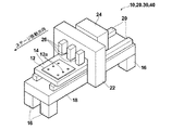
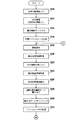
以下、図面を参照して本発明の描画点データ取得方法および装置並びに描画方法および装置の第1の実施形態を用いた露光装置について詳細に説明する。図1は、本発明の第1の実施形態を用いた露光装置の概略構成を示す斜視図である。本発明の第1の実施形態を用いた露光装置は、多層プリント配線板の各層の配線パターンを露光する装置であって、その各層の配線パターンを露光するために用いられる露光点データの取得方法に特徴を有するものであるが、まずは、露光装置の概略構成について説明する。 Hereinafter, a drawing point data acquisition method and apparatus and an exposure apparatus using the first embodiment of the drawing method and apparatus according to the present invention will be described in detail with reference to the drawings. FIG. 1 is a perspective view showing a schematic configuration of an exposure apparatus using the first embodiment of the present invention. An exposure apparatus using the first embodiment of the present invention is an apparatus for exposing a wiring pattern of each layer of a multilayer printed wiring board, and an exposure point data acquisition method used for exposing the wiring pattern of each layer First, the schematic configuration of the exposure apparatus will be described.
露光装置10は、図1に示すように、基板12を表面に吸着して保持する平板状の移動ステージ14を備えている。そして、4本の脚部16に支持された厚い板状の設置台18の上面には、ステージ移動方向に沿って延びた2本のガイド20が設置されている。移動ステージ14は、その長手方向がステージ移動方向を向くように配置されると共に、ガイド20によって往復移動可能に支持されている。
As shown in FIG. 1, the
設置台18の中央部には、移動ステージ14の移動経路を跨ぐようにコの字状のゲート22が設けられている。コの字状のゲート22の端部の各々は、設置台18の両側面に固定されている。このゲート22を挟んで一方の側にはスキャナ24が設けられ、他方の側には基板12の先端および後端と、基板12に予め設けられている円形状の複数の基準マーク12aの位置とを検知するための複数のカメラ26が設けられている。
A
ここで、基板12における基準マーク12aは、予め設定された基準マーク位置情報に基づいて基板12上に形成された、たとえば孔である。なお、孔の他にランドやヴィアやエッチングマークを用いてもよい。また、基準マーク12aとして、基板12上に露光される、回路パターンの一部などの所定のパターンを利用するようにしてもよい。また、図1においては、基準マーク12aを6個しか示していないが実際には多数の基準マーク12aが設けられている。また、基準マーク12aとして、基板12のエッジを検出するようにしてもよい。
Here, the
スキャナ24およびカメラ26はゲート22に各々取り付けられて、移動ステージ14の移動経路の上方に固定配置されている。なお、スキャナ24およびカメラ26は、これらを制御する後述するコントローラに接続されている。
The
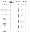
スキャナ24は、図2および図3(B)に示すように、2行5列の略マトリックス状に配列された10個の露光ヘッド30(30A〜30J)を備えている。
As shown in FIGS. 2 and 3B, the
各露光ヘッド30の内部には、図4に示すように入射された光ビームを空間変調する空間光変調素子(SLM)であるデジタル・マイクロミラー・デバイス(DMD)36が設けられている。DMD36は、マイクロミラー38が直交する方向に2次元状に多数配列されたものであり、そのマイクロミラー38の列方向が走査方向と所定の設定傾斜角度θをなすように取り付けられている。したがって、各露光ヘッド30による露光エリア32は、走査方向に対して傾斜した矩形状のエリアとなる。ステージ14の移動に伴い、基板12には露光ヘッド30ごとに帯状の露光済み領域34が形成される。なお、各露光ヘッド30に光ビームを入射する光源については図示省略してあるが、たとえば、レーザ光源などを利用することができる。
Inside each
露光ヘッド30の各々に設けられたDMD36は、マイクロミラー38単位でオン/オフ制御され、基板12には、DMD36のマイクロミラー38に対応したドットパターン(黒/白)が露光される。前述した帯状の露光済み領域34は、図4に示すマイクロミラー38に対応した2次元配列されたドットによって形成される。二次元配列のドットパターンは、走査方向に対して傾斜されていることで、走査方向に並ぶドットが、走査方向と交差する方向に並ぶドット間を通過するようになっており、高解像度化を図ることができる。なお、傾斜角度の調整のバラツキによって、利用しないドットが存在する場合もあり、たとえば、図4では、斜線としたドットは利用しないドットとなり、このドットに対応するDMD36におけるマイクロミラー38は常にオフ状態となる。
The
また、図3(A)および(B)に示すように、帯状の露光済み領域34のそれぞれが、隣接する露光済み領域34と部分的に重なるように、ライン状に配列された各行の露光ヘッド30の各々は、その配列方向に所定間隔ずらして配置されている。このため、たとえば、1行目の最も左側に位置する露光エリア32A、露光エリア32Aの右隣に位置する露光エリア32Cとの間の露光できない部分は、2行目の最も左側に位置する露光エリア32Bにより露光される。同様に、露光エリア32Bと、露光エリア32Bの右隣に位置する露光エリア32Dとの間の露光できない部分は、露光エリア32Cにより露光される。
Further, as shown in FIGS. 3A and 3B, the exposure heads of the respective rows arranged in a line so that each of the strip-shaped exposed
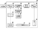
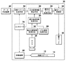
次に、露光装置10の電気的構成について説明する。露光装置10は、図5に示すように、CAM(Computer Aided Manufacturing)ステーションを有するデータ作成装置40から出力された、基板12に露光すべき露光画像を表わすベクトル形式の露光画像データを取得し、その取得したベクトル形式の露光画像データに基づいて、後述する中間ベクトルデータを生成する中間ベクトル生成手段50、カメラ26により撮影された基準マーク12aの画像に基づいて基準マーク12aの検出位置情報を取得する検出位置情報取得手段52と、検出位置情報取得手段52により取得された検出位置情報に基づいて、実際の露光の際の基板12上における各マイクロミラー38の露光軌跡の情報を取得する露光軌跡情報取得手段54と、露光軌跡情報取得手段54により取得された各マイクロミラー38毎の露光軌跡情報と中間ベクトル生成手段50から出力された中間ベクトルデータに基づいて、上記露光軌跡情報に対応する上記中間ベクトルデータ上における露光点データ軌跡と中間ベクトルデータによって表わされるベクトルとの交点の配置を示す交点配置情報を算出する交点配置情報算出手段56と、交点配置情報算出手段56により算出された交点配置情報に基づいて、各マイクロミラー38毎の露光点データ軌跡に対応する露光点データを取得する露光点データ取得手段58と、露光点データ取得手段58により取得された各マイクロミラー38毎の露光点データに基づいて露光ヘッド30のDMD36を制御する露光ヘッド制御部59と、移動ステージ14をステージ移動方向へ移動させる移動機構60と、本露光装置全体を制御するコントローラ70とを備えている。なお、移動機構60は、移動ステージ14をガイド20に沿って往復移動させるものであれば如何なる既知の構成を採用してもよい。また、上記中間ベクトルデータ、上記露光点データ軌跡および交点配置置情報などや、上記各構成要素の作用については後で詳述する。
Next, the electrical configuration of the
次に、上記第1の実施形態を用いた露光装置10の作用について図面を参照しながら説明する。
Next, the operation of the
まず、データ作成装置40において、基板12に露光すべき露光画像の元のベクトル形式の露光画像データが作成される。そして、そのベクトル形式の露光画像データは中間ベクトル生成手段50に入力され、中間ベクトル生成手段50は、入力されたベクトル形式の露光画像データに基づいて中間ベクトルデータを生成する。中間ベクトルデータとは、ベクトル形式の露光画像データにより表わされる露光画像の輪郭をベクトル形式のデータで表わしたものある。図6(A)にベクトル形式の露光画像データで表わされる露光画像の一例を示すとともに、図6(B)に図6(A)で示される露光画像の露光画像データに基づいて生成された中間ベクトルデータによって表わされるベクトルを示す。なお、図6(A)における斜線部分が露光画像データにより表わされる露光画像であり、図6(B)における矢印が中間ベクトルデータによって表わされるベクトルである。また、ここでいうベクトルとは、直線により表わされるものだけでなく、図6(B)に示すように曲線により表わされるものも含むものとする。中間ベクトルデータの生成方法については、たとえば、上記ベクトル形式の露光画像データが領域ベクトルデータである場合には、その領域ベクトルデータにおける輪郭を示すデータを用いて中間ベクトルデータを生成するようにすればよい。また、上記ベクトル形式の露光画像データが線分の方向を示すデータとその線分の太さを示すデータからなるものである場合には、上記太さを示すデータに基づいて領域ベクトルデータに変換し、その領域ベクトルデータにおける輪郭を示すデータを用いて中間ベクトルデータを生成するようにすればよい。
First, in the
なお、中間ベクトルデータを形成する際に、輪郭を表すベクトルを境界として一方の側がオンであるかオフであるかを示す情報を付加しておいてもよい。たとえば、Yが増える方向がオンもしくはオフ(Y方向に平行なベクトルの場合はXが増える方向がオンもしくはオフ)という情報を付加してもよいし、予め始点から終点に向いて右側がオンで左側がオフと決めた上で輪郭ベクトルを生成してもよい。このように中間ベクトルデータを形成しておくことによって、後述する露光点データの取得の際に、オンとオフの割り振りを容易に行うことができる。 When forming the intermediate vector data, information indicating whether one side is on or off may be added with a vector representing an outline as a boundary. For example, information that the direction in which Y increases is on or off (in the case of a vector parallel to the Y direction, the direction in which X increases is on or off) may be added, or the right side is on from the start point to the end point in advance. The contour vector may be generated after the left side is determined to be off. By forming the intermediate vector data in this way, on and off allocation can be easily performed when exposure point data to be described later is acquired.
また、本実施形態においては、図6(A)に示すように、2つの露光画像が重なって配置されている場合には、図6(B)および図7に示すように、2つの露光画像を結合して1本の輪郭により表わされる1つの露光画像とし、その1つの露光画像の中間ベクトルデータを生成するものとする。ただし、このような態様に限られることなく、重なった2つの露光画像について、それぞれの中間ベクトルデータを生成するようにしてもよい。 In the present embodiment, as shown in FIG. 6A, when two exposure images are arranged so as to overlap each other, as shown in FIG. 6B and FIG. Are combined into one exposure image represented by one contour, and intermediate vector data of the one exposure image is generated. However, the present invention is not limited to such a mode, and intermediate vector data may be generated for two overlapping exposure images.
そして、上記のようにして生成された中間ベクトルデータは、中間ベクトル生成手段50から交点配置情報算出手段56に出力される。 The intermediate vector data generated as described above is output from the intermediate vector generation means 50 to the intersection arrangement information calculation means 56.
一方、上記のように中間ベクトルデータが生成されるとともに、各露光ヘッド30のDMD36の各マイクロミラー38毎の、実際の露光の際の基板12上における露光軌跡の情報が取得される。なお、多層基板を形成するときには、下層のパターンに合わせて上層のパターンを描画する必要があるが、その場合には、基板上の画像空間上における露光軌跡が規定されることになる。
On the other hand, the intermediate vector data is generated as described above, and the information of the exposure locus on the
具体的には、露光装置10全体の動作を制御するコントローラ70が移動機構60に制御信号を出力し、移動機構60はその制御信号に応じて移動ステージ14を図1に示す位置からガイド20に沿って一旦上流側に移動させた後、ステージ移動方向へ所望の速度で移動させる。
Specifically, a
そして、上記のようにして移動する移動ステージ14上の基板12が複数のカメラ26の下を通過する際、これらのカメラ26により基板12が撮影され、その撮影画像を表す撮影画像データが検出位置情報取得手段52に入力される。検出位置情報取得手段52は、入力された撮影画像データに基づいて基板12の基準マーク12aの位置を示す検出位置情報を取得する。基準マーク12aの検出位置情報の取得方法については、たとえば、円形状の画像を抽出することにより取得するようにすればよいが、他の如何なる既知の取得方法を採用してもよい。また、上記基準マーク12aの検出位置情報は、具体的には座標値として取得されるが、その座標値の原点は、たとえば、基板12の撮影画像データの4つの角のうちの1つの角のとしてもよいし、撮影画像データにおける予め設定された所定の位置でもよいし、複数の基準マーク12aのうちの1つの基準マーク12aの位置としてもよい。なお、上記検出位置情報と基準マーク位置情報の座標系は一致しているものとする。また、本実施形態においては、カメラ26と検出位置情報取得手段52とにより位置情報検出手段が構成されている。
When the
そして、上記のようにして取得された基準マーク12aの検出位置情報は、検出位置情報取得手段52から露光軌跡情報取得手段54に出力される。
The detected position information of the
そして、露光軌跡情報取得手段54において、入力された検出位置情報に基づいて、実際の露光の際の基板12上における各マイクロミラー38毎の露光軌跡の情報が取得される。具体的には、露光軌跡情報取得手段54には、予め各露光ヘッド30のDMD36の各マイクロミラー38が通過する位置を示す通過位置情報が、各マイクロミラー38毎に設定されている。上記通過位置情報は、移動ステージ14上の基板12の設置位置に対する、各露光ヘッド30の設置位置によって決定されるものであって予め設定されている。そして、上記基準マーク位置情報および上記検出位置情報と同じ点を原点として、ベクトルまたは複数点の座標値で表わされるものである。なお、通過位置情報の座標系も、上記基準マーク位置情報および上記検出位置情報の座標系と一致しているものとする。図8に、プレスエ程などを経ていない理想的な形状の基板12、つまり、歪などの変形が生じておらず、基準マーク12aが予め設定された基準マーク位置情報12bの示す位置に配置している基板12と、所定のマイクロミラー38の通過位置情報12cとの関係を示す模式図を示す。なお、基板12上におけるビームスポットの位置を測定した結果に基づいて、通過位置情報を求めるようにしてもよい。
Then, in the exposure trajectory information acquisition means 54, information on the exposure trajectory for each micromirror 38 on the
そして、露光軌跡情報取得手段54において、図9に示すように、走査方向に直交する方向について隣接する検出位置情報12dを結ぶ直線と各マイクロミラー38の通過位置情報12cにより表わされる直線との交点の座標値が求められる。つまり、図9における×印の点の座標値が求められ、さらに、×印とその×印に上記直交する方向に隣接する各検出位置情報12dとの距離が求められ、上記隣接する検出位置情報12dのうちの一方の検出位置情報12dと×印との距離と、他方の検出位置情報12dと×印との距離との比が求められる。具体的には、図9におけるa1:b1、a2:b2、a3:b3およびa4:b4が露光軌跡情報として求められる。上記ようにして求められた比が、変形後の基板12上におけるマイクロミラー38の露光軌跡を表わしていることになる。つまり、実際の露光の際の基板12上におけるマイクロミラー38の露光軌跡(基板12上の画像空間上の露光軌跡)を表わしていることになる。
Then, in the exposure trajectory information acquisition means 54, as shown in FIG. 9, the intersection of the straight line connecting the adjacent
そして、上記のようにして各マイクロミラー38毎に求められた露光軌跡情報が、交点配置情報算出手段56に入力される。 Then, the exposure trajectory information obtained for each micromirror 38 as described above is input to the intersection arrangement information calculation means 56.
交点配置情報算出手段56には、図10に示すような、中間ベクトルデータの座標系が予め設定されている。なお、上記中間ベクトルデータの座標系は露光画像データの座標系でもあり、この座標系と、基準マーク位置情報、検出位置情報および通過位置情報の座標系は全て一致しているものとする。そして、座標系には、図10に示すように、上記基準マーク位置情報12bが示す位置に対応した位置に露光画像データ基準位置情報12eが配置されている。そして、交点配置情報算出手段56においては、まず、走査方向に直交する方向に隣接する露光画像データ基準位置情報12eを結ぶ直線を、上記のようにして求めた露光軌跡情報の示す比に基づいて分割した点の座標値が求められる。つまり、以下の式を満たすような点の座標値が求められる。
In the intersection arrangement
a1:b1=A1:B1
a2:b2=A2:B2
a3:b3=A3:B3
a4:b4=A4:B4
そして、上記のようにして求められた分割点を結ぶ直線が求められる。上記直線は、実際の露光の際の基板12上におけるマイクロミラー38の露光軌跡に対応する露光画像データ上における露光点データ軌跡を示すものである。
a1: b1 = A1: B1
a2: b2 = A2: B2
a3: b3 = A3: B3
a4: b4 = A4: B4
Then, a straight line connecting the division points obtained as described above is obtained. The straight line indicates the exposure point data locus on the exposure image data corresponding to the exposure locus of the
なお、上記のように露光軌跡情報の示す比に基づいて求められた分割点を直線で結び、その直線を露光点データ軌跡としてもよいし、上記分割点をスプライン補間などによって曲線で結び、その曲線を露光点データ軌跡として取得するようにしてもよい。上記のようにスプライン補間などによって曲線で結ぶようにすれば、より基板12の変形に忠実な露光点データ軌跡を取得することができる。また、上記スプライン補間などの演算方法に基板12の材質の特性(たとえば、特定の方向にしか伸縮しないなど)を反映するようにすれば、さらに、より基板12の変形に忠実な露光点データ軌跡を取得することができる。
As described above, the division points obtained based on the ratio indicated by the exposure trajectory information may be connected by straight lines, and the straight lines may be used as exposure point data trajectories, or the division points may be connected by curves by spline interpolation, etc. You may make it acquire a curve as an exposure point data locus. If the lines are connected by a curved line by spline interpolation or the like as described above, an exposure point data locus that is more faithful to the deformation of the
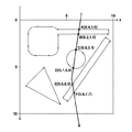
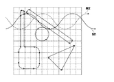
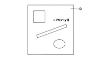
そして、図11に示すように、上記のようにして求められた露光点データ軌跡と中間ベクトルデータとが同じ座標系にプロットされ、中間ベクトルデータによって表わされるベクトルと露光点データ軌跡との交点の配置情報が求められる。交点配置情報とは、ここでは、上記交点の座標値である。つまり、図11に示す交点A〜Fの座標値が取得される。なお、図11に示す交点A〜Fで区切られた露光点データ軌跡が、部分描画点データ軌跡である。 Then, as shown in FIG. 11, the exposure point data trajectory obtained as described above and the intermediate vector data are plotted in the same coordinate system, and the intersection of the vector represented by the intermediate vector data and the exposure point data trajectory is plotted. Placement information is required. Here, the intersection arrangement information is the coordinate value of the intersection. That is, the coordinate values of the intersections A to F shown in FIG. 11 are acquired. Note that the exposure point data trajectory delimited by the intersections A to F shown in FIG. 11 is the partial drawing point data trajectory.
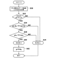
ここで、上記交点配置情報の算出の方法について具体的に説明する。ここでは、たとえば、中間ベクトルデータによって表わされるベクトルが下式(1)で表わされる線分であり、露光点データ軌跡が下式(2)で表わされる線分である場合の交点配置情報の算出方法について、図12のフローチャートを用いて説明する。 Here, a method of calculating the intersection arrangement information will be specifically described. Here, for example, calculation of intersection arrangement information when the vector represented by the intermediate vector data is a line segment represented by the following expression (1) and the exposure point data locus is a line segment represented by the following expression (2). The method will be described with reference to the flowchart of FIG.
x=a1y+b1,xs1≦x≦xe1,ys1≦y≦ye1 ・・・(1)
x=a2y+b2,xs2≦x≦xe2,ys2≦y≦ye2 ・・・(2)
図12のフローチャートに示すように、まず、式(1)におけるa1と式(2)におけるa2とが比較され、つまり両直線の傾きが比較され(S10)、これらが同じである場合には、交点がないものとして演算を終了する(S12)。一方、S10においてa1とa2が異なる値である場合には、交点の計算が行われる(S14)。具体的には以下の演算により交点のx座標とy座標とが算出される。
x = a 1 y + b 1 , x s1 ≦ x ≦ x e1 , y s1 ≦ y ≦ y e1 (1)
x = a 2 y + b 2 , x s2 ≦ x ≦ x e2 , y s2 ≦ y ≦ y e2 (2)
As shown in the flowchart of FIG. 12, first, a1 in equation (1) and a2 in equation (2) are compared, that is, the slopes of both straight lines are compared (S10), and when these are the same, The calculation is terminated assuming that there is no intersection (S12). Meanwhile, a 1 and a 2 is in the case of different values, the intersection calculation is performed in S10 (S14). Specifically, the x coordinate and the y coordinate of the intersection are calculated by the following calculation.
a1y+b1=a2y+b2より
y=(b2−b1)/(a1−a2)
x=a1y+b1
そして、次に、上記のようにして求められた交点のy座標の大きさをys2およびye2と比較することによって、上記交点が露光点データ軌跡上に存在するか否かが確認される(S16)。そして、ys2<y≦ye2を満たさない場合には、交点がないものとして演算を終了する(S12)。一方、ys2<y≦ye2を満たす場合には、ys1とye1が同じ値かどうかを確認することによって、中間ベクトルデータによって表わされるベクトルがx軸に対して平行かどうかが確認される(S18)。そして、上記ベクトルがx軸に対して平行でない場合には、y座標の大きさをys1とye1と比較することによって、上記のようにしても求めた交点が、中間ベクトルデータによって表わされるベクトル上に存在するか否かが確認される(S20)。そして、ys1<y≦ye1を満たさない場合には、交点がないものとして演算を終了する(S12)。一方、ys1<y≦ye1を満たす場合には、交点があるものとして上記のようにして求めたx座標、y座標が取得される。また、S18において、中間ベクトルデータによって表わされるベクトルがx軸に対して平行であると確認された場合には、x座標の大きさをxs1とxe1と比較することによって、上記のようにして求めた交点が、中間ベクトルデータによって表わされるベクトル上に存在するか否かが確認される(S22)。そして、xs1<x≦xe1を満たさない場合には、交点がないものとして演算を終了する(S24)。一方、xs1<x≦xe1を満たす場合には、交点があるものとして上記ようにして求めたx座標、y座標が取得される。
y than a 1 y + b 1 = a 2 y +
x = a 1 y + b 1
Then, the magnitude of the y coordinate of the intersection obtained as described above is compared with y s2 and y e2 to confirm whether the intersection exists on the exposure point data locus. (S16). If y s2 <y ≦ y e2 is not satisfied, the calculation is terminated assuming that there is no intersection (S12). On the other hand, when y s2 <y ≦ y e2 is satisfied, whether or not the vector represented by the intermediate vector data is parallel to the x axis is confirmed by checking whether y s1 and y e1 are the same value. (S18). If the vector is not parallel to the x-axis, the intersection obtained as described above is represented by the intermediate vector data by comparing the y coordinate size with y s1 and y e1. It is confirmed whether or not it exists on the vector (S20). If y s1 <y ≦ y e1 is not satisfied, the calculation is terminated assuming that there is no intersection (S12). On the other hand, when y s1 <y ≦ y e1 is satisfied, the x-coordinate and the y-coordinate obtained as described above are acquired as if there is an intersection. If it is confirmed in S18 that the vector represented by the intermediate vector data is parallel to the x axis, the size of the x coordinate is compared with x s1 and x e1 as described above. It is confirmed whether or not the obtained intersection point exists on the vector represented by the intermediate vector data (S22). Then, when x s1 <x ≦ x e1 is not satisfied, the calculation is terminated assuming that there is no intersection (S24). On the other hand, when x s1 <x ≦ x e1 is satisfied, the x-coordinate and the y-coordinate obtained as described above are obtained assuming that there is an intersection.
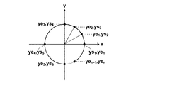
次に、中間ベクトルデータによって表わされるベクトルが下式(3)で表わされる曲線(円弧)であり、露光点データ軌跡が下式(4)で表わされる線分である場合の交点配置情報の算出方法について、図13のフローチャートを用いて説明する。 Next, calculation of intersection arrangement information when the vector represented by the intermediate vector data is a curve (arc) represented by the following equation (3) and the exposure point data locus is a line segment represented by the following equation (4): A method is demonstrated using the flowchart of FIG.
(x−a1)2+(y−b1)2=c2 ・・・(3)
x=a2y+b2,xs≦x≦xe,ys≦y≦ye ・・・(4)
図13のフローチャートに示すように、まず、上式(3)と上式(4)とに基づいて、これらの交点が計算される(S30)。なお、ここでは、上式(3)を下式(5)のように、上式(4)を下式(6)のように円の中心を原点とした座標系に変換した後、これらの交点(X,Y)が求められる。
(X−a 1 ) 2 + (y−b 1 ) 2 = c 2 (3)
x = a 2 y + b 2 , x s ≦ x ≦ x e , y s ≦ y ≦ y e (4)
As shown in the flowchart of FIG. 13, first, the intersections of these are calculated based on the above equations (3) and (4) (S30). Here, after converting the above equation (3) into the coordinate system with the center of the circle as the origin, like the following equation (5), and the above equation (4) as the following equation (5), The intersection (X, Y) is determined.
X=x−a1,Y=y−b1とすると上式(3)は、
X2+Y2=c2 ・・・(5)
同じくX=x−a1,Y=y−b1とすると上式(4)は、
X=a2Y+d,d=b2+a2b1−a1,
xs−a1≦X≦xe−a1,ys−b1≦Y≦ye−b1 ・・・(6)
そして、上式(5)および上式(6)に基づいて求められた交点が0または1つである場合には、交点なしとして演算を終了する(S34)。なお、ここでは、接点は交点ではないとしている。一方、交点が2つ以上ある場合には、Y座標の大きさを(ys−b1)と(ye―b1)と比較することによって、上記のようにしても求められた交点が露光点データ軌跡上に存在するか否かが確認される(S36)。そして、ys−b1<Y≦ye−b1を満たさない場合には交点なしとして演算を終了する(S34)。一方、ys−b1<Y≦ye−b1を満たす場合には、Y座標の大きさがysnおよびyen(nは1以上の自然数)と比較されることによって、上記のようにしても求められた交点が上式(5)で示される円上のいずれかの円弧上に存在するか否かが確認される。なお、上記ysnおよびyenは、図14に示すように円弧のベクトルを各象限毎に分割した際におけるそれぞれの円弧のY座標の範囲を示す値である。そして、ysn<Y≦yenを満たさない場合には交点はないものとして演算を終了する(S34)。一方、ysn<Y≦yenを満たす場合には、上式(5)で示される円上のいずれかの円弧上に上記交点が存在するものとする(S40)。そして、S38において交点があるとされた場合には、下式(7)を計算することによってY座標を元の座標系に戻し、交点のy座標を取得する(S42)。
When X = x−a 1 and Y = y−b 1 , the above equation (3) is
X 2 + Y 2 = c 2 (5)
Similarly, if X = xa 1 and Y = yb 1 , the above equation (4) is
X = a 2 Y + d, d = b 2 + a 2 b 1 −a 1 ,
x s −a 1 ≦ X ≦ x e −a 1 , y s −b 1 ≦ Y ≦ y e −b 1 (6)
When the number of intersections obtained based on the above formula (5) and the above formula (6) is 0 or 1, the calculation is terminated as no intersection (S34). Here, the contact point is not an intersection. On the other hand, when there are two or more intersections, the intersection obtained as described above can be obtained by comparing the size of the Y coordinate with (y s −b 1 ) and (y e −b 1 ). It is confirmed whether or not it exists on the exposure point data locus (S36). If y s −b 1 <Y ≦ y e −b 1 is not satisfied, the calculation is terminated with no intersection (S34). On the other hand, when y s −b 1 <Y ≦ y e −b 1 is satisfied, the size of the Y coordinate is compared with y sn and y en (where n is a natural number of 1 or more), as described above. Even so, it is confirmed whether or not the obtained intersection exists on any arc on the circle represented by the above equation (5). Note that y sn and y en are values indicating the range of the Y coordinate of each arc when the arc vector is divided into each quadrant as shown in FIG. If y sn <Y ≦ y en is not satisfied, the calculation is terminated assuming that there is no intersection (S34). On the other hand, when y sn <Y ≦ y en is satisfied, it is assumed that the intersection point exists on any arc on the circle represented by the above equation (5) (S40). If it is determined in S38 that there is an intersection, the following equation (7) is calculated to return the Y coordinate to the original coordinate system, and the y coordinate of the intersection is obtained (S42).
y=Y+b1 ・・・(7)
そして、上記のようにして取得された交点A〜Fのy座標が露光点データ取得手段58に出力され、露光点データ取得手段58において、入力された交点y座標に基づいて各マイクロミラー38毎の露光点データ列が取得される。具体的には、露光点データ取得手段58は、図15に示すように、交点A〜Fのy座標をプロットし、そのプロットされたy座標に基づいて2値化露光点データを割り当てる。なお、図15に示すy座標−1は、マイクロミラー38の初期位置に対応するy座標の値である。
y = Y + b1 (7)
Then, the y-coordinates of the intersections A to F acquired as described above are output to the exposure point
そして、さらに、図15に示すように、y座標−1〜10までの間の間隔を0.5のピッチで区切り、y座標−1から10までの間を0.5ピッチで2値化露光画像データをサンプリングして露光点データを取得して、図15に示すような、各マイクロミラー38毎の露光点データ列を取得する。なお、後述するようにピッチが一定でない場合もある。 Further, as shown in FIG. 15, the interval between y coordinates -1 to 10 is divided by a pitch of 0.5, and the interval from y coordinates -1 to 10 is binarized at a pitch of 0.5. Image data is sampled to obtain exposure point data, and an exposure point data string for each micromirror 38 as shown in FIG. 15 is obtained. As will be described later, the pitch may not be constant.
そして、上記と同様にして、各マイクロミラー38毎について露光点データ列がそれぞれ取得され、その各マイクロミラー38毎の露光点データ列が露光ヘッド制御部59に出力される。
In the same manner as described above, an exposure point data string is acquired for each micromirror 38 and the exposure point data string for each micromirror 38 is output to the
一方、上記のように各マイクロミラー38毎の露光点データ列が露光ヘッド制御部59に出力されるとともに、移動ステージ14が、図1に示す下流側の位置から上流側へ所望の速度で移動させられる。
On the other hand, as described above, the exposure point data sequence for each micromirror 38 is output to the
そして、基板12の先端がカメラ26により検出されると露光が開始される。具体的には、露光ヘッド制御部59から各露光ヘッド30のDMD36に上記露光点データに基づいた制御信号が出力され、露光ヘッド30は入力された制御信号に基づいてDMD36のマイクロミラーをオン・オフさせて基板12を露光する。
Then, when the tip of the
なお、露光ヘッド制御部59から各露光ヘッド30へ制御信号が出力される際には、基板12に対する各露光ヘッド30の各位置に対応した制御信号が、移動ステージ14の移動にともなって順次露光ヘッド制御部59から各露光ヘッド30に出力されるが、このとき、たとえば、図16に示すように、各マイクロミラー38毎に取得されたm個の露光点データ列の各列から、各露光ヘッド30の各位置に応じた露光点データを1つずつ順次読み出して各露光ヘッド30のDMD36に出力するようにしてもよいし、図16に示すように取得された露光点データ列に90度回転処理もしくは行列を用いた転置変換などを施し、図17に示すように、基板12に対する各露光ヘッド30の各位置に応じたフレームデータ1〜mを生成し、このフレームデータ1〜mを各露光ヘッド30に順次出力するようにしてもよい。
When a control signal is output from the
なお、上記第1の実施形態においては、露光点データ取得手段58における露光点データの取得方法については、上記のような取得方法に限らず、たとえば、図18に示すように、取得された交点のy座標の値をサンプリングピッチである0.5でそれぞれ割った後、整数化して量子化値を取得し、その隣接する量子化値の差をそれぞれ取得してこの差をランレングスデータとみなし、これをデコードすることによって、図18に示すような露光点データ列を取得するようにしてもよい。なお、上記のようにして露光点データ列を取得する際、露光点データ列の先頭にマイクロミラーの初期位置に対応する0のデータを付加するようにすれば、図15に示す露光点データ列と同様のものを取得することができる。
In the first embodiment, the exposure point data acquisition method in the exposure point
なお、上記説明においては、プレス工程などにおいて変形した基板12に露光する際の露光点データの取得方法について説明したが、変形してない理想的な形状の基板12に露光する際についても、上記と同様の方法を採用して露光点データを取得することができる。また、基板の変形を考慮する必要がない場合も同様である。これらの場合には、基板12上における露光軌跡に基づいて、輪郭ベクトルと露光点データ軌跡との交点が求められる。
In the above description, the method for acquiring exposure point data when exposing the
さらに、たとえば、図19に示すように、走査方向について基板12が伸縮している場合には、その伸縮の程度に応じて、露光点データ取得手段58において、露光点データのサンプリングピッチを変化させるようにしてもよい。具体的には、たとえば、上記のように走査方向に基板12が伸縮し、検出位置情報12dと通過位置情報12cとが図19に示すような関係となり、走査方向に隣接する検出位置情報12dの間隔が、理想的な長さLの領域Aと、基板12が走査方向に伸びての上記間隔が長さLの2倍となった領域Bと、基板12が走査方向に縮んで上記間隔が長さLの1/2となった領域Cとが存在する場合には、たとえば、領域Aに対応する露光点データについては、サンプリングピッチを通常の0.5として露光点データをサンプリングし、領域Bに対応する露光点データについては、サンプリングピッチを通常のサンプリングピッチの1/2の0.25として露光点データをサンプリングし、領域Cの露光点データについては、サンプリングピッチを通常のサンプリングピッチの2倍の1.0として露光点データをサンプリングするようにしてもよい。なお、上記説明においては、基板12が走査方向にのみ伸縮した場合における露光点データの取得方法を説明したが、上記のような場合に限らず、その他の方向にも基板12が変形している場合においても、検出位置情報12dで区切られた領域毎に、マイクロミラー38の通過位置情報の長さが異なる場合には、上記と同様にその長さに応じてサンプリングピッチを変化させるようにしてもよい。上記のように基板12の伸縮に応じてサンプリングピッチを変化させるようにすれば、基板12上の所望の位置に所望の露光画像を露光することができる。
Further, for example, as shown in FIG. 19, when the
また、上記実施形態においては、露光軌跡情報取得手段54において、基準マーク位置情報と検出位置情報とに基づいて露光軌跡情報を取得するようにしたが、必ずしも基板12の変形を考慮して露光軌跡情報を取得するようにしなくてもよく、たとえば、露光軌跡情報取得手段54において、基板12の設置位置に対する各露光ヘッド30の設置位置によって予め設定された通過位置情報を露光軌跡情報として取得し、その通過位置情報を交点配置情報算出手段56に出力し、交点配置情報算出手段56において、通過位置情報と中間ベクトルデータによって表わされるベクトルとの交点を算出し、この交点のy座標に基づいて上記と同様にして露光点データを取得するようにしてもよい。上記のような場合には、必ずしも基準マーク12aを設ける必要はない。また、図1に示す基準マーク12aは、後述する実施形態においても、使用しない場合には必ずしも設ける必要はない。基板12の設置位置の誤差は、たとえば、基板12のエッジを検出することによって求めることができる。
In the above embodiment, the exposure trajectory
次に、本発明の描画点データ取得方法および装置並びに描画方法および装置の第2の実施形態を用いた露光装置20について詳細に説明する。露光装置20の外観の概略構成については、図1に示す本発明の第1の実施形態を用いた露光装置10と同様である。
Next, the drawing point data acquisition method and apparatus of the present invention and the
露光装置20は、図20に示すように、中間ベクトル生成手段50と、移動ステージ14のステージ移動方向と直交する方向へのずれ情報を取得するずれ情報取得手段80と、ずれ情報取得手段80に取得されたずれ情報に基づいて、実際の露光の際の基板12上における各マイクロミラー38の露光軌跡の情報を取得する露光軌跡情報取得手段82と、露光軌跡情報取得手段82により取得された各マイクロミラー38毎の露光軌跡情報と中間ベクトル生成手段50から出力された中間ベクトルデータに基づいて、上記露光軌跡情報に対応する上記中間ベクトルデータ上における露光点データ軌跡と中間ベクトルデータによって表わされるベクトルとの交点の配置を示す交点配置情報を算出する交点配置情報算出手段84と、交点配置情報算出手段84により算出された交点配置情報に基づいて各マイクロミラー38毎の露光点データを取得する露光点データ取得手段85と、露光ヘッド制御部59と、移動機構60と、本露光装置全体を制御するコントローラ70とを備えている。なお、図20において図5と同じ符号を付している構成については、上記本発明の第1の実施形態を用いた露光装置10とその作用は同様である。
As illustrated in FIG. 20, the
次に、露光装置20の作用について図面を参照しながら説明する。
Next, the operation of the
まず、中間ベクトル生成手段50から交点配置情報算出手段84に中間ベクトルデータを出力するまでの作用については上記と同様である。
First, the operation until the intermediate vector data is output from the intermediate
そして、次に、ずれ情報取得手段80によって移動ステージ14のステージ移動方向への移動のずれ情報が取得される。ずれ情報とは、図21に示すように、予め設定されたステージ移動方向(所定相対移動方向)に対する、実際の移動ステージ14の移動方向(実移動方向)のずれを示したものである。具体的には、図21に示すように、予め設定されたステージ移動方向への移動軌跡に対する実際の移動ステージ14の移動軌跡の、ステージ移動方向に直交する方向についてのずれ量を所定の間隔で取得したものである。図21に示す点線矢印の向きと長さがずれ量を示すものである。
Then, deviation information on movement of the moving
ここで、上記のように移動ステージ14の移動軌跡にずれがある場合、露光の際の各マイクロミラー38の基板12上における実際の露光軌跡は、図22に示すように、予め設定された各マイクロミラー38の通過位置情報12cに対して上記ずれ量に応じてずれることになる。したがって、各マイクロミラー38の実際の露光軌跡に対応した露光点データを取得する必要がある。また、図22に示すように、マイクロミラーm1とマイクロミラーm2とは、基板12上における同じ位置を通過するものであるが、上記のような移動ステージ14の移動軌跡にずれがあると、これらの実際の露光軌跡は位相がずれたものになる。したがって、これらの位相ずれも考慮して露光点データを取得する必要がある。
Here, when there is a deviation in the movement locus of the moving
そこで、露光装置20においては、上記のような各マイクロミラー38の露光軌跡のずれ量に応じた露光点データが取得される。具体的には、予め移動ステージ14のずれ量が計測され、その計測されたずれ量が、上記のようにしてずれ量取得手段80によって取得される。そして、ずれ量取得手段80は、取得したずれ量を露光軌跡情報取得手段82に出力する。ずれ量の計測方法としては、たとえば、ICウェーハ・ステッパー装置などで利用されるレーザ光を用いた測定方法を用いることができる。たとえば、移動ステージ14に、ステージ移動方向に延びる反射面を設けるとともに、その反射面に向けてレーザ光を射出するレーザ光源および上記反射面において反射した反射光を検出する検出部を設け、移動ステージ14の移動にともなって、反射光の位相ずれを順次検出部により検出することによって上記ずれ量を計測することができる。
Therefore, the
露光軌跡情報取得手段82には、各マイクロミラー38毎の通過位置情報12cが設定されており、露光軌跡情報取得手段82は、入力されたずれ量と各マイクロミラー38毎の通過位置情報12cに基づいて、露光の際の各マイクロミラー38毎の基板12上における実際の露光軌跡を表わす露光軌跡情報を取得する。なお、上記通過位置情報12cについては、上記第1の実施形態を用いた露光装置10の説明と同様である。
Passing
そして、その各マイクロミラー38毎の露光軌跡情報を交点配置情報算出手段84に出力する。交点配置情報算出手段84は、入力された露光軌跡情報を露光点データ軌跡として、図23に示すように、中間ベクトルデータと同じ座標系にプロットし、上記第1の実施形態と同様に、中間ベクトルデータによって表わされるベクトルと露光点データ軌跡との交点の配置情報を求める。なお、交点配置情報の算出方法については上記と同様である。 Then, the exposure trajectory information for each micromirror 38 is output to the intersection arrangement information calculation means 84. The intersection arrangement information calculation means 84 plots the input exposure trajectory information as an exposure point data trajectory in the same coordinate system as the intermediate vector data as shown in FIG. 23, and in the same way as in the first embodiment, Arrangement information of the intersection of the vector represented by the vector data and the exposure point data locus is obtained. Note that the method for calculating the intersection arrangement information is the same as described above.
なお、図23に示す露光点データ軌跡M1は、図22に示すマイクロミラーm1の露光点データ軌跡であり、図23に示す露光点データ軌跡M2は、図22に示すマイクロミラーm2の露光点データ軌跡である。 23 is the exposure point data locus of the micromirror m1 shown in FIG. 22, and the exposure point data locus M2 shown in FIG. 23 is the exposure point data of the micromirror m2 shown in FIG. It is a trajectory.
そして、上記のようにして取得された交点配置情報のy座標の値が露光点データ取得手段85に出力され、露光点データ取得手段85において、入力された交点y座標に基づいて各マイクロミラー38毎の露光点データ列が取得される。露光点データ列の取得方法については上記と同様である。
Then, the value of the y coordinate of the intersection arrangement information acquired as described above is output to the exposure point
そして、各マイクロミラー38毎について露光点データ列がそれぞれ取得され、その各マイクロミラー38毎の露光点データ列が露光ヘッド制御部59に出力される。
Then, an exposure point data string is acquired for each micromirror 38 and the exposure point data string for each micromirror 38 is output to the
一方、上記のように各マイクロミラー38毎の露光点データ列が露光ヘッド制御部59に出力されるとともに、移動ステージ14が、図1に示す下流側の位置から上流側へ所望の速度で移動させられる。
On the other hand, as described above, the exposure point data sequence for each micromirror 38 is output to the
そして、基板12の先端がカメラ26により検出されると露光が開始される。具体的には、露光ヘッド制御部59から各露光ヘッド30のDMD36に上記露光点データに基づいた制御信号が出力され、露光ヘッド30は入力された制御信号に基づいてDMD36のマイクロミラーをオン・オフさせて基板12を露光する。
Then, when the tip of the
次に、本発明の描画点データ取得方法および装置並びに描画方法および装置の第3の実施形態を用いた露光装置30について詳細に説明する。
Next, the drawing point data acquisition method and apparatus and the
露光装置30は、図24に示すように、上記第1の実施形態を用いた露光装置10の構成と上記第2の実施形態を用いた露光装置20の構成とを両方兼ね備えたものである。
As shown in FIG. 24, the
露光装置30においては、上述のようにして検出位置情報取得手段52において取得された基準マーク12aの検出位置情報と、上述のようにしてずれ情報取得手段80において取得されたずれ情報とが、露光軌跡情報取得手段86に入力される。
In the
そして、露光軌跡情報取得手段86は、入力された上記検出位置情報と上記ずれ情報とに基づいて、露光の際の各マイクロミラー38毎の基板12上における実際の露光軌跡(画像空間上における露光軌跡)を表わす露光軌跡情報を取得する。
Then, the exposure trajectory information acquisition means 86, based on the input detected position information and the deviation information, the actual exposure trajectory (exposure on the image space) on the
具体的には、露光軌跡情報取得手段86において、上記第1の実施形態と同様に、走査方向に直交する方向について隣接する検出位置情報12d同士を結ぶ直線と各マイクロミラー38の通過位置情報12cを表わす直線との交点の座標値が求められ、その交点とその交点に上記直交する方向に隣接する各検出位置情報12dとの距離が求められ、上記隣接する検出位置情報12dのうちの一方の検出位置情報12dと交点との距離と、他方の検出位置情報12dと交点との距離との比が求められる。
Specifically, in the exposure trajectory information acquisition means 86, as in the first embodiment, a straight line connecting the adjacent
一方、露光軌跡情報取得手段86は、上記第2の実施形態と同様に、入力されたずれ量と各マイクロミラー38毎の通過位置情報12cに基づいて、図23に曲線で示されるような、各マイクロミラー38毎の基板12上における仮露光軌跡情報を取得する。
On the other hand, the exposure trajectory information acquisition means 86, as in the second embodiment, is based on the input shift amount and the passing
そして、露光軌跡情報取得手段86は、上記のようにして求められた比と仮露光軌跡情報とを露光軌跡情報として交点配置情報算出手段88に出力する。
Then, the exposure trajectory
そして、交点配置情報算出手段88は、上記第1の実施形態と同様に、図25に示すように、走査方向に直交する方向に隣接する露光画像データ基準位置情報12eを結ぶ直線を、入力された比に基づいて分割した点を求めた後、その点を結ぶ直線を求め、その直線の走査方向に対する傾き分だけ仮露光軌跡情報を傾けて露光軌跡情報を表わす曲線M1’およびM2’を求め、その曲線を露光点データ軌跡として取得する。なお、図25におけるA1:B1、A2:B2は、露光軌跡情報取得手段86から入力された比がa1:b1、a2:b2である場合に、a1:b1=A1:B1、a2:b2=A2:B2を満たすような比である。
Then, as in the first embodiment, as shown in FIG. 25, the intersection arrangement
そして、上記と同様にして、各マイクロミラー38毎の露光点データ軌跡が求められる。 In the same manner as described above, an exposure point data locus for each micromirror 38 is obtained.
そして、交点配置情報算出手段88は、上記のようにして求められた露光点データ軌跡を、上記と同様に、中間ベクトルデータと同じ座標系にプロットし、中間ベクトルデータによって表わされるベクトルと露光点データ軌跡との交点の配置情報を求める。なお、交点配置情報の算出方法については上記と同様である。 Then, the intersection arrangement information calculation means 88 plots the exposure point data trajectory obtained as described above in the same coordinate system as the intermediate vector data in the same manner as described above, and the vector and the exposure point represented by the intermediate vector data. Find the location information of the intersection with the data trajectory. Note that the method for calculating the intersection arrangement information is the same as described above.
そして、上記のようにして取得された交点配置情報のy座標の値が露光点データ取得手段89に出力され、露光点データ取得手段89において、入力された交点y座標に基づいて各マイクロミラー38毎の露光点データ列が取得される。露光点データ列の取得方法については上記と同様である。
Then, the value of the y coordinate of the intersection arrangement information acquired as described above is output to the exposure point
そして、各マイクロミラー38毎について露光点データ列がそれぞれ取得され、その各マイクロミラー38毎の露光点データ列が露光ヘッド制御部59に出力される。
Then, an exposure point data string is acquired for each micromirror 38 and the exposure point data string for each micromirror 38 is output to the
一方、上記のように各マイクロミラー38毎の露光点データ列が露光ヘッド制御部59に出力されるとともに、移動ステージ14が、図1に示す下流側の位置から上流側へ所望の速度で移動させられる。
On the other hand, as described above, the exposure point data sequence for each micromirror 38 is output to the
そして、基板12の先端がカメラ26により検出されると露光が開始される。具体的には、露光ヘッド制御部59から各露光ヘッド30のDMD36に上記露光点データに基づいた制御信号が出力され、露光ヘッド30は入力された制御信号に基づいてDMD36のマイクロミラーをオン・オフさせて基板12を露光する。
Then, when the tip of the
次に、本発明の描画点データ取得方法および装置並びに描画方法および装置の第4の実施形態を用いた露光装置40について詳細に説明する。露光装置40の外観の概略構成については、図1に示す本発明の第1の実施形態を用いた露光装置10と同様である。
Next, the drawing point data acquisition method and apparatus and the
露光装置40は、図26に示すように、上記第1の実施形態を用いた露光装置10の構成に加えてさらに、基板12の移動の速度変動情報を予め取得する速度変動情報取得手段90を備えている。そして露光点データ取得手段91は、速度変動情報取得手段90により取得された速度変動情報に基づいて、移動ステージ14の移動の速度が遅いほどサンプリングピッチを短くする。なお、図26において図5と同じ符号を付している構成については、上記第1の実施形態を用いた露光装置10とその作用は同様である。また、上記基板12の移動の速度変動情報とは、本実施形態においては、移動ステージ14の移動機構60の制御精度に応じて発生する移動速度のムラである。
26, in addition to the configuration of the
図27は、実際の露光の際の基板12上における所定のマイクロミラー38の露光軌跡とそのマイクロミラー38により露光点を露光するタイミングとを表わしたものである。なお、図27における点線矢印が、移動ステージの速度変動がない場合におけるマイクロミラー38の露光軌跡と露光タイミングとを表わしたものであり、実線矢印が、移動ステージの速度変動がある場合におけるマイクロミラー38の露光軌跡と露光タイミングを表わしたものである。そして、直線上において矢印を付した部分がマイクロミラー38による露光点の露光タイミングを示している。なお、図27においては、説明の都合上、2つの露光軌跡を別々の直線で示しているが、これらの露光軌跡は同一のマイクロミラーの露光軌跡である。そして、図27におけるP1〜P8は、基板12上に露光される画像を構成する各画素を示したものである。また、露光タイミングと移動ステージ14の移動速度とは、所望の解像度で基板12上に露光画像が露光されるように相対的な関係をもって予め設定されているものである。
FIG. 27 shows the exposure trajectory of a
図27に示すように、移動ステージ14の速度変動がない場合には、各画素P1〜P8は、マイクロミラー38によって1つの露光点により露光される。つまり、1つの画素に対して、マイクロミラー38が露光する露光点の数は1つである。
As shown in FIG. 27, when there is no fluctuation in the speed of the moving
一方、移動ステージ14の速度変動がある場合には、各画素P1〜P8を露光する露光点の数は、その速度変動に応じて異なる。具体的には、1つの画素の幅を移動ステージ14が移動する間に露光タイミングが2回以上ある場合には、つまり相対的に遅い速度で移動ステージ14が移動して露光される領域は、各画素は2以上の露光点によって露光されることになる。そして、1つの画素の幅を移動ステージ14が移動する間に露光タイミングが全くない場合には、つまり相対的に速い速度で移動ステージ14が移動して露光される領域は、各画素は露光されない。
On the other hand, when there is a speed variation of the moving
図27においては、画素P1,P5を露光する際には、移動ステージ14は相対的に遅い速度で移動し、画素P4,P8を露光する際には、移動ステージ14は相対的に早い速度で移動し、画素P2,P3,P6,P7を露光する際には、移動ステージ14は予め設定された一定の速度で移動している。
In FIG. 27, when the pixels P1 and P5 are exposed, the moving
したがって、上記のような移動ステージの速度変動に応じて露光点データを取得する必要がある。 Therefore, it is necessary to acquire exposure point data according to the speed fluctuation of the moving stage as described above.
そこで、露光点データ取得手段91は速度変動情報取得手段90により取得された速度変動情報に応じた数の露光点データが取得されるように、サンプリングピッチを変化させる。速度変動情報とは、具体的には、たとえば、所定の露光タイミングピッチにおける移動ステージ14のステージ移動方向への移動距離の変動情報であり、速度変動情報取得手段90に予め設定される。
Therefore, the exposure point
そして、上記のように速度変動情報取得手段90に予め設定された速度変動情報が、露光点データ取得手段91に出力され、露光点データ取得手段91は、たとえば、移動ステージ14の移動速度に変化がない場合には、サンプリングピッチを通常のサンプリングピッチ0.5として露光点データを取得し、移動ステージ14の移動速度に変化がある場合には、その速度変動に応じたサンプリングピッチで露光点データを取得する。たとえば、図27の実線矢印で示したような速度変動がある場合には、画素P1および画素P5を露光するための露光点データを取得する際には、サンプリングピッチを短くして3つの露光点データが取得されるようにする。また、画素P4および画素P8を露光するための露光点データを取得する際には、サンプリングピッチを長くして露光点データを取得しないようにする。そして、画素P2,P3,P6,P7を露光するための露光データを取得する際には、通常のサンプリングピッチとして1つの露光点データを取得するようにする。
Then, the speed fluctuation information preset in the speed fluctuation information acquisition means 90 as described above is output to the exposure point data acquisition means 91, and the exposure point data acquisition means 91 changes, for example, to the movement speed of the moving
そして、上記のようにして取得された露光点データが移動ステージ14の移動に応じて順次露光ヘッド制御部59に出力され、露光ヘッド制御部59から各露光ヘッド30のマイクロミラー38にその露光点データに応じた制御信号が出力され、その制御信号に応じてマイクロミラーがオン・オフされて基板12に露光点が露光される。
The exposure point data acquired as described above is sequentially output to the exposure
なお、上記第4の実施形態の露光装置40において、検出位置情報取得手段52により検出位置情報を取得し、その検出位置情報に基づいて露光軌跡情報取得手段54において露光軌跡情報を取得し、交点配置情報算出手段56において、上記露光軌跡情報に基づいて露光点データ軌跡を求めた後、その露光点データ軌跡と中間ベクトルデータによって表わされるベクトルとの交点を求め、その交点のy座標に2値化露光画像データを割り当てるまでの作用については、上記第1の実施形態の露光装置10と同様である。そして、上記のようにして割り当てられた2値化露光画像データからサンプリングして露光点データを取得する際に、上記のような方法を採用することができる。
In the
また、上記第2、第3の実施形態の露光装置においても、上記と同様の方法を用いて露光点データを取得するようにすることができる。その場合においても露光点データ軌跡と中間ベクトルデータによって表わされるベクトルとの交点を求め、その交点のy座標に2値化露光画像データを割り当てるまでの作用については、上記第2、第3の実施形態の露光装置と同様である。 Also in the exposure apparatuses of the second and third embodiments, exposure point data can be obtained using the same method as described above. Even in this case, the second and third implementations described above are performed until the intersection of the exposure point data locus and the vector represented by the intermediate vector data is obtained and the binarized exposure image data is assigned to the y coordinate of the intersection. It is the same as that of the exposure apparatus of the form.
また、上記第2の実施形態の露光装置において、上記第4の実施形態の露光装置のように速度変動情報に応じて取得する露光点データの数を変化させるようにすれば、たとえば、移動ステージ14の蛇行を補正できるだけでなく、ヨーイングも考慮した補正を行うことができる。なお、ヨーイングとは、移動ステージ14の蛇行に、移動ステージ14の回転が加わったものである。上記のような移動ステージ14の回転により、各マイクロミラー38の基板12上の像の位置が変化するとともに、所定の露光タイミングピッチにおける移動ステージ14のステージ移動方向への移動距離が変化することになるので、つまり上記回転により移動ステージ14の局所的速度変動が生じるので、上記像の位置変動および速度変動情報に応じて露光点データの数を変化させるようにすればよい。なお、蛇行成分を0として回転成分のみを考慮してもよい。
Further, in the exposure apparatus of the second embodiment, if the number of exposure point data acquired according to the speed variation information is changed as in the exposure apparatus of the fourth embodiment, for example, a moving stage In addition to correcting 14 meanders, it is possible to perform correction in consideration of yawing. Note that yawing is the meandering of the moving
また、上記第1〜第4の実施形態を全て用いた露光装置とすることもできる。そのように構成した場合における露光装置の作用について、図28および図29のフローチャートを用いて簡単に説明する。なお、詳細な作用については上記説明と同様である。 Further, an exposure apparatus that uses all of the first to fourth embodiments can be used. The operation of the exposure apparatus in such a configuration will be briefly described with reference to the flowcharts of FIGS. The detailed operation is the same as described above.
まず、露光軌跡情報取得手段54に各露光ヘッド30のDMD36の各マイクロミラー38の通過位置情報が入力設定され(S10)、移動ステージ14のずれ情報および速度変動情報がそれぞれずれ情報取得手段80、速度変動情報取得手段90に入力設定される(S12)。そして、データ作成装置40において作成されたベクトル形式の露光画像データが中間ベクトル生成手段50に入力され(S14)、中間ベクトル生成手段50において、上記露光画像データに基づいて中間ベクトルデータが生成され、その中間ベクトルデータは交点配置情報算出手段56に出力される(S16)。
First, the passage position information of each
一方、上記のように中間ベクトルデータが生成されるとともに、露光装置10全体の動作を制御するコントローラ70が移動機構60に制御信号を出力し、移動機構60はその制御信号に応じて移動ステージ14を図1に示す位置からガイド20に沿って一旦上流側の所定の初期位置まで移動させた後、ステージ移動方向へ所望の速度で移動させる(S18)。
On the other hand, the intermediate vector data is generated as described above, and the
そして、上記のようにして移動する移動ステージ14上の基板12に基準マーク12aがカメラ26によって撮影され、その撮影画像データに基づいて検出位置情報取得手段52によって検出位置情報が取得される(S20)
そして、上記のようにして取得された検出位置情報が、検出位置情報取得手段52から露光軌跡情報取得手段54に出力されるとともに、ずれ情報取得手段において設定されたずれ情報が露光軌跡情報取得手段54に出力される。そして、露光軌跡情報取得手段54において、基板12上における各マイクロミラー38の露光軌跡情報が算出されるが、具体的には、まず、第1の実施形態の露光装置において説明したように、走査方向に直交する方向について隣接する検出位置情報12dを結ぶ直線と各マイクロミラー38の通過位置情報12cを表わす直線との交点の座標値が求められ、上記交点とその交点に上記直交する方向に隣接する各検出位置情報12dとの距離が求められ、上記隣接する検出位置情報12dのうちの一方の検出位置情報12dと上記交点との距離と、他方の検出位置情報12dと上記交点との距離との比が求められる。具体的には、図9におけるa1:b1、a2:b2、a3:b3およびa4:b4が露光軌跡情報として求められる。なお、上記比は、上記のようにして取得された検出位置情報からずれ量を差し引いた後に求められる。(S20)。
And the
The detected position information acquired as described above is output from the detected position
また、露光軌跡情報取得手段54においては、上記のような比が算出されるとともに、入力されたずれ量と各マイクロミラー38の通過位置情報とに基づいて各マイクロミラー38毎の仮露光軌跡情報が求められ、この仮露光軌跡情報と上記比とが露光軌跡情報として取得され、交点配置情報算出手段56に出力される。なお、比と仮露光軌跡を求める順番は逆でもよい。そして、交点配置情報算出手段56においては、図25で説明したようにして露光軌跡情報に対応する露光点データ軌跡を表わす曲線が求められ(S24)、上記のようにして求められた露光点データ軌跡を、上記と同様に、中間ベクトルデータと同じ座標系にプロットし、中間ベクトルデータによって表わされるベクトルと露光点データ軌跡との交点の配置情報を求める(S26)。交点配置情報の算出方法については上記と同様である。
Further, the exposure trajectory information acquisition means 54 calculates the ratio as described above, and provisional exposure trajectory information for each micromirror 38 based on the input shift amount and the passing position information of each
そして、上記のようにして取得された交点配置情報のy座標の値が露光点データ取得手段58に出力され、そのy座標の値に基づいて、上記のように2値化露光画像データが割り当てられる(S28)。 Then, the value of the y coordinate of the intersection arrangement information acquired as described above is output to the exposure point data acquisition means 58, and the binarized exposure image data is assigned as described above based on the value of the y coordinate. (S28).
そして、露光点データ取得手段58には、速度変動情報取得手段90において取得された速度変動情報が入力され、上記第4の実施形態の露光装置において説明したように、上記速度変動情報に応じたサンプリングピッチが設定され、そのサンプリングピッチで2値化露光画像データがサンプリングされて各マイクロミラー38毎の露光点データ列が取得される(S30)。露光点データ列の取得方法については上記と同様である。 The exposure point data acquisition means 58 receives the speed fluctuation information acquired by the speed fluctuation information acquisition means 90, and as described in the exposure apparatus of the fourth embodiment, it corresponds to the speed fluctuation information. A sampling pitch is set, and binarized exposure image data is sampled at the sampling pitch, and an exposure point data string for each micromirror 38 is acquired (S30). The method for obtaining the exposure point data string is the same as described above.
なお、このとき速度変動情報だけでなく、基板12の走査方向への伸縮も考慮して、つまり、基板12の検出位置情報12dで区切られた領域毎のマイクロミラー38の通過位置情報の長さも考慮してサンプリングピッチを決定することが望ましい。
At this time, not only the speed variation information but also the expansion / contraction in the scanning direction of the
そして、上記のようにして取得された各マイクロミラー38毎の露光点データの列に90度回転処理もしくは行列を用いた転置変換などが施され、図17に示すように、基板12に対する各露光ヘッド30の各位置に応じたフレームデータ1〜mが生成される(S32)。
Then, a 90 degree rotation process or a transposition conversion using a matrix is performed on the exposure point data column for each micromirror 38 acquired as described above, and each exposure on the
一方、上記のようにフレームデータ1〜mが生成されるとともに、移動ステージ14が、図1に示す下流側の位置から上流側へ所望の速度で移動させられる。そして、基板12の先端がカメラ26により検出されると露光が開始され、上記フレームデータ1〜mが移動ステージ14の移動に応じて各露光ヘッド30にその位置に応じて順次出力され、各露光ヘッド30によりフレームデータに基づいた露光画像が基板12上に露光される(S34)。そして、全てのフレームデータが露光ヘッド30に入力され、露光が終了すると再び移動ステージ14は上流側に移動する(S36)。そして、次の基板12がある場合にはその基板12に交換された後、再びS16からの処理が行われ、次の基板12がない場合にはそのまま終了する(S34)。
On the other hand, the
上記第1〜第4の実施形態の露光装置によれば、露光画像を表わすベクトル形式の露光画像データを取得するとともに、露光画像の露光の際の基板12上におけるマイクロミラー38の露光軌跡の情報を取得し、露光画像データにより表わされる露光画像の輪郭と露光軌跡情報に対応する露光画像データ上における露光点データ軌跡との交点の配置を示す交点配置情報を取得し、交点配置情報に基づいて露光点データ軌跡に対応した露光点データを取得するようにしたので、従来のようにベクトル形式の露光画像データをラスター形式の露光画像データに変換することなくベクトル形式の露光画像データから直接露光点データを取得することができ、処理速度の低下およびコストアップを招くことなく、露光精度の向上を図ることができる。
According to the exposure apparatuses of the first to fourth embodiments, the exposure image data in the vector format representing the exposure image is acquired, and the information on the exposure locus of the
図30に、上記第1〜第4の実施形態の露光装置の効果を視覚的に表わした模式図を示す。図30(A)はラスター形式の露光画像データを用いて露光した場合の露光画像を示す図であり、図30(B)はベクトル形式の露光画像データを用いて露光した場合の露光画像を示したものである。なお、図30(A),(B)における黒丸はマイクロミラーを示したものであり、点線矢印はマイクロミラーとそのマイクロミラーにより露光される露光画素との対応関係を示したものである。 FIG. 30 is a schematic diagram visually showing the effects of the exposure apparatuses of the first to fourth embodiments. FIG. 30A is a diagram showing an exposure image when exposed using raster format exposure image data, and FIG. 30B shows an exposure image when exposed using vector format exposure image data. It is a thing. In FIGS. 30A and 30B, black circles indicate micromirrors, and dotted arrows indicate the correspondence between micromirrors and exposure pixels exposed by the micromirrors.
また、上記第1の実施形態の露光装置のように、基板12上の所定位置に予め設けられた複数の基準マーク12aを検出してその基準マーク12aの位置を示す検出位置情報12dを取得し、その取得した検出位置情報12dに基づいて露光軌跡情報を取得するようにした場合には、たとえば、基板12に変形が生じたような場合でも、その変形後の基板12上におけるマイクロミラー38の露光軌跡の情報を予め取得し、その露光軌跡情報に対応した露光点データを露光画像データから取得することができるので、上記変形に応じた露光画像を基板12上に描画することができる。したがって、たとえば、多層プリント配線板を形成する際には、各層の配線パターンをその各層の変形に応じて形成することができるので各層の配線パターンの位置合わせを高精度に行うことができる。
Further, like the exposure apparatus of the first embodiment, a plurality of
また、上記第2および第3の実施形態の露光装置のように、予め設定された基板12の所定移動方向に対する露光画像の露光の際の基板12の実移動方向のずれ情報を取得し、その取得したずれ情報に基づいて露光軌跡情報を取得するようにした場合には、基板12の移動方向にずれが生じた場合においても、その移動方向のずれに応じた露光軌跡の情報を予め取得し、その露光軌跡情報に対応した露光点データを露光画像データから取得することができるので、上記移動方向のずれに影響されることなく基板12上の所望の位置に所望の露光画像を描画することができる。
Further, as in the exposure apparatuses of the second and third embodiments, the information on the deviation of the actual movement direction of the
また、上記第4の実施形態の露光装置のように、予め設定された基板12の所定移動速度に対する露光画像の露光の際の基板12の実移動速度の変動を示す速度変動情報を取得し、その取得した速度変動情報に基づいて、基板12の実移動速度が相対的に遅い基板12上の露光領域ほど描画点データの数が多くなるようにサンプリングピッチを変化させて露光点データを取得するようにした場合には、移動ステージ14の移動速度のムラに影響されることなく、基板12上の所望の位置に所望の露光画像を露光することができる。
Further, as in the exposure apparatus of the fourth embodiment, the speed fluctuation information indicating the fluctuation of the actual movement speed of the
また、上記第1〜第4の実施形態の露光装置においては、上記のようにベクトル形式の露光画像データ上に、基板12の変形などに応じて取得された露光点データ軌跡を対応させて露光点データを取得するようにしたが、検出位置情報に対応させて露光画像データを変形し、その変形した露光画像データと同様に変形した露光点データ軌跡とに基づいて露光点データを取得するようにしてもよい。なお、誤差の性質に応じて、画像データの変形で吸収するものと、露光点データ軌跡(ピッチ成分を含む)の変形で吸収するものとを分けるようにしてもよい。たとえば、基板の変形や設置位置の誤差は、画像データの変形で対応し、移動ステージの搬送誤差などは、露光点データ軌跡の変形で対応するようにしてもよい。この場合、移動ステージの搬送誤差などを考慮しなければ、露光点データ軌跡を不変とすることもできる。
In the exposure apparatuses of the first to fourth embodiments, exposure is performed in association with the exposure point data trajectory acquired according to the deformation of the
また、上記第1〜第4の実施形態の露光装置においては、中間ベクトルデータを生成し、この中間ベクトルデータを利用して露光点データ軌跡と露光画像データにより表される露光画像の輪郭の交点を求めるようにしたが、必ずしも中間ベクトルデータは生成しなくても上記交点を求めることができる。たとえば、図31に示すように、ベクトル形式の露光画像データが、方向と長さを示す線分データD1と太さデータD2とからなるものである場合には、まず、図31に矢印で示す露光点データ軌跡と線分データD1との交点0を求め、下式(1)より角度θ1を求め、その角度θ1に基づいて下式(2)よりOPの長さを求め、そのOPの長さに基づいて下式(3)より交点Pの座標を求めることができる。また、交点Qの座標も、上記と同様に、θ1、θ2、θ3、QPおよびOxとOyに基づいて求めるようにすればよい。なお、図31におけるL1およびL2はx方向に平行な直線である。
In the exposure apparatuses of the first to fourth embodiments, intermediate vector data is generated, and the intersection of the exposure point contour and the exposure image contour represented by the exposure image data is generated using the intermediate vector data. However, the intersection point can be obtained without necessarily generating intermediate vector data. For example, as shown in FIG. 31, when the exposure image data in the vector format is composed of line segment data D1 indicating the direction and length and thickness data D2, first, an arrow is shown in FIG. The
θ1=θ3−θ2 ・・・ (1)
OP=(D2/2) × (1/sinθ1) ・・・(2)
Px=Ox + OP×cosθ3、Py=Oy + OP×sinθ3 ・・・ (3)
但し、Pxは交点Pのx座標、Pyは交点Pのy座標
Oxは点Oのx座標、Oyは点Oのy座標
また、ベクトル形式の露光画像データから露光点データを取得する方法としては、上記第1〜第4の実施形態で説明した方法に限らず、その他の方法も考えることができる。たとえば、図32に示すように、基板12上における露光点P1の位置に対応する露光画像データD上の位置座標(x1,y1)を取得し、ベクトル形式の露光画像データDと上記位置座標(x1,y1)とに基づいて露光点の露光点データを取得することができる。具体的には、たとえば、ベクトル形式の露光画像データが、図33に示すように、方向と長さを示す線分データD1と太さデータD2とからなるものである場合には、露光点P1と線分D1との距離L3を求め、L3とD2/2との大きさを比較して露光点P1が露光画像データにより表される露光画像上にあるか否かを判定し、露光画像上にある場合には、そのベクトル形式の露光画像データにより示される値を露光点P1の露光点データとして取得するようにすればよい。なお、上記ベクトル形式の露光画像データにより示される値は2値に限らず、多値でもよい。一方、露光点P1が露光画像上にない場合には、露光点P1の露光点データとして0を取得するようにすればよい。
θ1 = θ3−θ2 (1)
OP = (D2 / 2) × (1 / sin θ1) (2)
Px = Ox + OP × cos θ3, Py = Oy + OP × sin θ3 (3)
However, Px is the x coordinate of the intersection point P, Py is the y coordinate of the intersection point P, Ox is the x coordinate of the point O, Oy is the y coordinate of the point O, and a method of acquiring exposure point data from exposure image data in vector format. In addition to the methods described in the first to fourth embodiments, other methods can be considered. For example, as shown in FIG. 32, the position coordinates (x1, y1) on the exposure image data D corresponding to the position of the exposure point P1 on the
また、上記露光点P1の位置座標は、図34に示すように、基板12上の所定位置におけるマイクロミラー38の位置を示すものとすることができる。
Further, the position coordinates of the exposure point P1 can indicate the position of the
また、図35に示すように、露光画像データDに基づいて決定される複数の露光画像と露光点P1の位置座標を含む線L4とを重ね合わせ、線L4が重なる露光画像の露光画像データに基づいて露光点データを取得するようにすることができる。 Further, as shown in FIG. 35, a plurality of exposure images determined based on the exposure image data D and the line L4 including the position coordinates of the exposure point P1 are superimposed, and the exposure image data of the exposure image where the line L4 overlaps is obtained. Based on this, exposure point data can be acquired.
また、図36に示すように、上記線L4を、基板12上におけるマイクロミラー38の露光軌跡とすることができる。
In addition, as shown in FIG. 36, the line L4 can be the exposure locus of the
また、図37に示すように、上記線L4を、基板12上の所定位置におけるDMD36の各マイクロミラー38を結ぶ直線とすることができる。この場合、まず、ベクトルの開始点の位置座標(たとえば、所定の1つのマイクロミラーの位置座標)を取得した後、この始点から延びる直線と露光画像データDの輪郭ベクトルとの交点を計算し、各交点間もしくはそれ以外の区間に含まれるマイクロミラーについて露光点データを算出する。直線の形状は、ビームスポットの配列に基づいて固定値として設定してもよいし、上述の露光軌跡の場合と同様に、基板の変形や移動ステージの搬送誤差などを考慮して変形したものとしてもよい。
As shown in FIG. 37, the line L4 can be a straight line connecting the
また、図38に示すように、露光画像データに基づいて決定される複数の露光画像と露光点P1の位置座標を含む所定領域Aとを重ね合わせ、所定領域Aが重なる露光画像の露光画像データに基づいて露光点データを取得するようにすることができる。 As shown in FIG. 38, a plurality of exposure images determined based on the exposure image data and a predetermined area A including the position coordinates of the exposure point P1 are overlaid, and the exposure image data of the exposure image where the predetermined area A overlaps. The exposure point data can be acquired based on the above.
また、図39に示すように、所定領域Aを、基板12上の所定位置におけるDMD36の領域とすることができる。たとえば、DMD36の像の全部または一部毎に、領域Aを設定するようにしてもよい。
Further, as shown in FIG. 39, the predetermined area A can be an area of the
また、図40(A),(B)に示すように、露光画像データD上における所定の矩形領域Sを設定し、その矩形領域S内について、DMD36の領域と露光画像との重なりを求め、その重なり部分の露光画像データに基づいて露光点P1の露光点データを取得するようにしてもよい。
Also, as shown in FIGS. 40A and 40B, a predetermined rectangular area S on the exposure image data D is set, and an overlap between the area of the
また、上記実施形態では、空間光変調素子としてDMDを備えた露光装置について説明したが、このような反射型空間光変調素子の他に、透過型空間光変調素子を使用することもできる。 In the above-described embodiment, the exposure apparatus including the DMD as the spatial light modulation element has been described. However, in addition to the reflective spatial light modulation element, a transmissive spatial light modulation element can also be used.
また、上記実施形態では、いわゆるフラッドベッドタイプの露光装置を例に挙げたが、感光材料が巻きつけられるドラムを有する、いわゆるアウタードラムタイプの露光装置としてもよい。 In the above embodiment, a so-called flood bed type exposure apparatus has been described as an example. However, a so-called outer drum type exposure apparatus having a drum around which a photosensitive material is wound may be used.
また、上記実施形態の露光対象である基板12は、プリント配線基板だけでなく、フラットパネルディスプレイの基板であってもよい。この場合、パターンは、カラーフィルター、ブラックマトリックス、TFTなどの半導体回路、その他の各種の構造体であってもよい。また、基板12の形状は、シート状のものであっても、長尺状のもの(フレキシブル基板など)であってもよい。
Moreover, the board |
また、本発明における描画方法および装置は、インクジェット方式などのプリンタにおける描画にも適用することができる。たとえば、インクの吐出による描画点を、本発明と同様に形成することができる。つまり、本発明における描画点形成領域を、インクジェット方式のプリンタの各ノズルから吐出されたインクが付着する領域として考えることができる。 The drawing method and apparatus according to the present invention can also be applied to drawing in a printer such as an inkjet method. For example, a drawing point by ink ejection can be formed in the same manner as in the present invention. That is, the drawing point formation region in the present invention can be considered as a region to which ink ejected from each nozzle of an ink jet printer adheres.
また、上記描画軌跡情報は、実際の基板上における描画点形成領域の描画軌跡を用いて描画軌跡情報としてもよいし、実際の基板上における描画点形成領域の描画軌跡を近似したものを描画軌跡情報としてもよいし、実際の基板上における描画点形成領域の描画軌跡を予測したものを描画軌跡情報としてもよい。 The drawing trajectory information may be drawn trajectory information using a drawing trajectory of a drawing point formation area on an actual substrate, or an approximation of a drawing trajectory of a drawing point formation area on an actual substrate. It is good also as information, and what estimated the drawing locus | trajectory of the drawing point formation area on an actual board | substrate is good also as drawing locus information.
また、基板の変形やステージの移動誤差に応じて、画像データ上におけるビームの軌跡を折れ線や曲線等の非直線で規定するのと同様に、ピッチ成分も非直線的に規定することができる。 Further, the pitch component can also be defined in a non-linear manner in the same manner as the beam trajectory on the image data is defined by a non-linear line such as a polygonal line or a curve in accordance with the deformation of the substrate or the stage movement error.
この場合、各ビーム軌跡に対応させて、ピッチ成分の情報を保持していることが好ましい。ただし、基板の位置ずれや傾きのみを考慮するような場合には、全てのビーム軌跡に共通のピッチ成分(この場合、ピッチ間隔も全て一定としてもよい)を割り当ててもよい。 In this case, it is preferable to hold information on the pitch component corresponding to each beam locus. However, when only the positional deviation and inclination of the substrate are taken into consideration, a common pitch component (in this case, all pitch intervals may be constant) may be assigned to all beam trajectories.
つまり、基板の位置補正及び基板搬送方向と直交する方向の画像変形補正は、ビーム軌跡の変化で対応し、基板搬送方向に沿った方向の画像変形補正は、ピッチ成分の変化で対応することができる。この場合、ビーム軌跡ごとにピッチ成分を与えておくことによって、局所的又は変形量が連続的に変化するような変形補正にも対応することができる。 In other words, the substrate position correction and the image deformation correction in the direction orthogonal to the substrate transport direction correspond to the change of the beam trajectory, and the image deformation correction in the direction along the substrate transport direction can correspond to the change of the pitch component. it can. In this case, by providing a pitch component for each beam trajectory, it is possible to cope with deformation correction in which a local or deformation amount changes continuously.
また、ピッチ成分は、ビーム軌跡ベクトルの向きに沿って設定してもよいし、ビーム軌跡ベクトルを所定の座標軸に投影したベクトルに沿って設定してもよい。 The pitch component may be set along the direction of the beam trajectory vector, or may be set along a vector obtained by projecting the beam trajectory vector onto a predetermined coordinate axis.
また、ピッチ成分に対応付けて、画像の輪郭とビーム軌跡との交点位置の情報を求めておく(例えば、交点位置をピッチ成分で与える)ことによって、ビーム軌跡に沿ったこの交点位置の情報の集まりを、圧縮データ的に扱うようにしてもよい。 Also, information on the intersection position between the contour of the image and the beam trajectory is obtained in association with the pitch component (for example, the intersection position is given as a pitch component), so that the information on the intersection position along the beam trajectory is obtained. You may make it handle gathering like compression data.
また、上記実施形態においては、2つ以上のマイクロミラー(ビーム)毎に1つの露光点データ軌跡を取得するようにしてもよい。たとえば、マイクロレンズアレイを構成する1つのマイクロレンズによって集光される複数のビーム毎に露光点データ軌跡を求めることができる。 In the above embodiment, one exposure point data locus may be acquired for every two or more micromirrors (beams). For example, the exposure point data trajectory can be obtained for each of a plurality of beams condensed by one microlens constituting the microlens array.
また、基板の変形等を画像データの変形で吸収する場合には、図41に示すように、輪郭ベクトルを変形させるようにしてもよい。この場合、たとえば、図5中の検出位置情報取得手段52から中間ベクトル生成手段50に、基準マーク12aの検出位置情報が供給される。
Further, when the deformation of the substrate or the like is absorbed by the deformation of the image data, the contour vector may be deformed as shown in FIG. In this case, for example, the detection position information of the
上記のように、本実施形態においては、ベクトル形式の画像データ上に規定した線(露光点データ軌跡)に基づいて、露光点データを求めることができるため、そのための計算を高速に行うことができる。ここで、線として上記露光軌跡情報に基づく露光軌跡ベクトルを用いた場合と、ビームスポット列に沿って規定したビーム列ベクトル(たとえば、図37の線L4)を用いた場合とにおける、計算量の違いについて説明する。露光軌跡ベクトルを用いた場合、交点計算の回数は、マイクロミラー数(たとえば、1024×240個)×対象となる露光画像データのベクトル数となるのに対して、ビーム列ベクトルを用いた場合は、ビーム列数(たとえば、240個)×対象となる露光画像データのベクトル数×フレーム数となる。この場合、フレーム数は、基板の長さ/露光ピッチで求められ、たとえば、1000000ほどの値となる。したがって、ビーム列ベクトルを用いた場合の方が計算量が多いことになる。一方、ビーム列ベクトルを用いた場合は、フレーム毎にデータを作成することができるため、リアルタイム性に優れている。つまり、ステージの振動などの非再現性の誤差原因にも対応可能である(図39の例のように、DMD36に対して所定領域Aを設ける場合も同様である)。
As described above, in the present embodiment, since the exposure point data can be obtained based on the line (exposure point data locus) defined on the image data in the vector format, the calculation for that can be performed at high speed. it can. Here, when the exposure trajectory vector based on the exposure trajectory information is used as a line, and when the beam train vector defined along the beam spot train (for example, the line L4 in FIG. 37) is used, Explain the difference. When the exposure trajectory vector is used, the number of times of intersection calculation is the number of micromirrors (eg, 1024 × 240) × the number of exposure image data vectors, whereas when the beam train vector is used. , The number of beam rows (for example, 240) × the number of target exposure image data vectors × the number of frames. In this case, the number of frames is obtained by the length of the substrate / exposure pitch, for example, a value of about 1 million. Therefore, the calculation amount is larger when the beam train vector is used. On the other hand, when a beam train vector is used, since data can be created for each frame, the real-time property is excellent. That is, it is possible to deal with non-reproducible error causes such as stage vibration (the same applies when the predetermined area A is provided for the
10,20,30,40 露光装置
12 基板
12a 基準マーク
12b 基準マーク位置情報
12c 通過位置情報
12d 検出位置情報
14 移動ステージ
18 設置台
20 ガイド
22 ゲート
24 スキャナ
26 カメラ
30 露光ヘッド(描画手段)
32 露光エリア
36 DMD
50 中間ベクトル生成手段
52 検出位置情報取得手段
54,82,86 露光軌跡情報取得手段(描画軌跡情報取得手段)
56,84,88 交点配置情報算出手段
58,85,91 露光点データ取得手段(描画点データ取得手段)
80 ずれ情報取得手段
90 速度変動情報取得手段
10, 20, 30, 40
32
50 Intermediate vector generation means 52 Detection position information acquisition means 54, 82, 86 Exposure locus information acquisition means (drawing locus information acquisition means)
56, 84, 88 Intersection arrangement information calculation means 58, 85, 91 Exposure point data acquisition means (drawing point data acquisition means)
80 Deviation information acquisition means 90 Speed fluctuation information acquisition means
Claims (46)
前記画像の元のベクトル形式の画像データを取得するとともに、前記描画対象上における前記描画点を形成すべき位置に対応する前記画像データ上の位置座標を取得し、
前記ベクトル形式の画像データと前記位置座標とに基づいて前記描画点の前記描画点データを取得することを特徴とする描画点データ取得方法。 In the drawing point data obtaining method for obtaining the drawing point data used when drawing the image on the drawing target by forming the drawing point on the drawing target based on the drawing point data,
Acquiring the original vector format image data of the image, and acquiring the position coordinates on the image data corresponding to the position where the drawing point should be formed on the drawing target,
A drawing point data acquisition method comprising: acquiring the drawing point data of the drawing point based on the vector format image data and the position coordinates.
前記画像の元のベクトル形式の画像データを取得するとともに、前記画像の描画のための前記描画対象上におけるまたは前記基板上の画像空間上における前記描画点形成領域の描画軌跡の情報を取得し、
前記画像データにより表わされまたは前記画像データから求められる画像の輪郭と前記描画軌跡情報に対応する前記画像データ上における描画点データ軌跡との交点の配置を示す交点配置情報を取得し、
前記交点配置情報に基づいて前記描画点データ軌跡に対応した前記描画点データを取得することを特徴とする描画点データ取得方法。 The drawing point forming area for forming the drawing point based on the drawing point data is moved relative to the drawing target, and the drawing point is sequentially formed on the drawing target in accordance with the movement, and the drawing target is formed. In the drawing point data acquisition method for acquiring the drawing point data used when drawing an image on the top,
Obtaining the original vector format image data of the image, and obtaining the drawing locus information of the drawing point formation region on the drawing object for drawing the image or on the image space on the substrate,
Obtaining intersection arrangement information indicating an arrangement of intersections of an image contour represented by the image data or obtained from the image data and a drawing point data locus on the image data corresponding to the drawing locus information;
The drawing point data acquisition method, wherein the drawing point data corresponding to the drawing point data locus is acquired based on the intersection arrangement information.
前記画像の元のベクトル形式の画像データを取得するとともに、前記描画対象上における前記描画点を形成すべき位置に対応する前記画像データ上の位置座標を取得し、
前記ベクトル形式の画像データと前記位置座標とに基づいて前記描画点の前記描画点データを取得し、
該取得した描画点データに基づいて前記描画点を前記描画対象上に形成することを特徴とする描画方法。 In a drawing method for forming a drawing point on a drawing target based on the drawing point data and drawing an image on the drawing target,
Acquiring the original vector format image data of the image, and acquiring the position coordinates on the image data corresponding to the position where the drawing point should be formed on the drawing target,
Obtaining the drawing point data of the drawing point based on the image data in the vector format and the position coordinates;
A drawing method, wherein the drawing points are formed on the drawing target based on the acquired drawing point data.
前記画像の元のベクトル形式の画像データを取得するとともに、前記画像の描画の際の前記描画対象上における前記描画点形成領域の描画軌跡の情報を取得し、
前記画像データにより表わされまたは前記画像データから求められる画像の輪郭と前記描画軌跡情報に対応する前記画像データ上における描画点データ軌跡との交点の配置を示す交点配置情報を取得し、
前記交点配置情報に基づいて前記描画点データ軌跡に対応した前記描画点データを取得し、
該取得した描画点データに基づいて前記描画点形成領域によって前記描画点を前記描画対象上に形成することを特徴とする描画方法。 The drawing point forming area for forming the drawing point based on the drawing point data is moved relative to the drawing target, and the drawing point is sequentially formed on the drawing target in accordance with the movement, and the drawing target is formed. In the drawing method of drawing an image on top,
Acquiring the original vector format image data of the image, and acquiring the drawing locus information of the drawing point formation region on the drawing target at the time of drawing the image,
Obtaining intersection arrangement information indicating an arrangement of intersections of an image contour represented by the image data or obtained from the image data and a drawing point data locus on the image data corresponding to the drawing locus information;
Obtaining the drawing point data corresponding to the drawing point data locus based on the intersection arrangement information;
A drawing method characterized in that the drawing point is formed on the drawing object by the drawing point formation region based on the acquired drawing point data.
前記描画対象上における前記描画点を形成すべき位置に対応する、前記画像の元のベクトル形式の画像データ上の位置座標を取得する位置座標取得手段と、
前記画像の元のベクトル形式の画像データを取得し、該取得したベクトル形式の画像データと前記位置座標取得手段により取得された位置座標とに基づいて前記描画点の前記描画点データを取得する描画点データ取得手段を備えたことを特徴とする描画点データ取得装置。 In a drawing point data acquisition apparatus for acquiring the drawing point data used when drawing an image on the drawing target by forming a drawing point on the drawing target based on the drawing point data,
Position coordinate acquisition means for acquiring position coordinates on image data in the original vector format of the image corresponding to a position where the drawing point on the drawing target is to be formed;
Drawing that acquires original vector format image data of the image and acquires the drawing point data of the drawing point based on the acquired vector format image data and the position coordinates acquired by the position coordinate acquisition means A drawing point data acquisition apparatus comprising point data acquisition means.
前記位置座標が、前記描画対象上の所定位置における前記描画点形成領域に対応するものであることを特徴とする請求項6記載の描画点データ取得装置。 The drawing point forming area for forming the drawing point based on the drawing point data is moved relative to the drawing target, and the drawing point is sequentially formed on the drawing target in accordance with the movement, and the drawing target is formed. A drawing point data acquisition device for acquiring the drawing point data used when drawing an image on the top,
The drawing point data acquisition apparatus according to claim 6, wherein the position coordinates correspond to the drawing point formation region at a predetermined position on the drawing target.
前記描画点データ取得手段が、前記交点配置情報取得手段により取得された交点配置情報に基づいて前記描画点データを取得するものであることを特徴とする請求項8記載の描画点データ取得装置。 Intersection arrangement information acquisition means for acquiring intersection arrangement information indicating an intersection of the contour of the image represented in the image data or obtained from the image data and the line,
9. The drawing point data acquisition apparatus according to claim 8, wherein the drawing point data acquisition means acquires the drawing point data based on the intersection arrangement information acquired by the intersection arrangement information acquisition means.
前記線が、時系列に並ぶ複数の前記描画点に対応する複数の前記位置座標を結ぶものであることを特徴とする請求項8記載の描画点データ取得装置。 The drawing point forming area for forming the drawing point based on the drawing point data is moved relative to the drawing target, and the drawing point is sequentially formed on the drawing target in accordance with the movement, and the drawing target is formed. A drawing point data acquisition device for acquiring the drawing point data used when drawing an image on the top,
9. The drawing point data acquiring apparatus according to claim 8, wherein the line connects a plurality of the position coordinates corresponding to the plurality of drawing points arranged in time series.
前記線が、前記描画対象上におけるまたは前記描画対象上の画像空間における前記描画点形成領域の描画軌跡に対応するものであることを特徴とする請求項8記載の描画点データ取得装置。 The drawing point forming area for forming the drawing point based on the drawing point data is moved relative to the drawing target, and the drawing point is sequentially formed on the drawing target in accordance with the movement, and the drawing target is formed. A drawing point data acquisition device for acquiring the drawing point data used when drawing an image on the top,
9. The drawing point data acquisition apparatus according to claim 8, wherein the line corresponds to a drawing locus of the drawing point formation region on the drawing target or in an image space on the drawing target.
前記線が、前記描画対象上の所定位置における前記描画点形成領域群の少なくとも一部の前記描画点形成領域を結ぶ線に対応するものであることを特徴とする請求項8記載の描画点データ取得装置。 A drawing point forming region group having a plurality of drawing point forming regions for forming drawing points based on the drawing point data is moved relative to the drawing target, and the drawing point forming region group is corresponded to the movement. A drawing point data acquisition device that sequentially forms a drawing point group to be drawn on the drawing target and acquires the drawing point data used when drawing an image on the drawing target;
9. The drawing point data according to claim 8, wherein the line corresponds to a line connecting at least a part of the drawing point forming areas of the drawing point forming area group at a predetermined position on the drawing target. Acquisition device.
前記所定領域が、前記描画対象上の所定位置における前記描画点形成領域群の少なくとも一部の領域に対応するものであることを特徴とする請求項17記載の描画点データ取得装置。 A drawing point forming region group having a plurality of drawing point forming regions for forming drawing points based on the drawing point data is moved relative to the drawing target, and the drawing point forming region group is corresponded to the movement. A drawing point data acquisition device that sequentially forms a drawing point group to be drawn on the drawing target and acquires the drawing point data used when drawing an image on the drawing target;
18. The drawing point data acquisition apparatus according to claim 17, wherein the predetermined area corresponds to at least a part of the drawing point formation area group at a predetermined position on the drawing target.
前記画像の描画のための前記描画対象上におけるまたは前記描画対象上の画像空間上における前記描画点形成領域の描画軌跡の情報を取得する描画軌跡情報取得手段と、
前記画像の元のベクトル形式の画像データを取得し、該取得した画像データにより表わされまたは前記画像データから求められる画像の輪郭と前記描画軌跡情報に対応する前記画像データ上における描画点データ軌跡との交点の配置を示す交点配置情報を取得する交点配置情報取得手段と、
該交点配置情報取得手段により取得された交点配置情報に基づいて前記描画軌跡に対応した前記描画点データを取得する描画点データ取得手段とを備えたことを特徴とする描画点データ取得装置。 The drawing point forming area for forming the drawing point based on the drawing point data is moved relative to the drawing target, and the drawing point is sequentially formed on the drawing target in accordance with the movement, and the drawing target is formed. In the drawing point data acquisition device for acquiring the drawing point data used when drawing an image on the top,
Drawing trajectory information acquisition means for acquiring information on a drawing trajectory of the drawing point formation region on the drawing target for drawing the image or on an image space on the drawing target;
The image data of the original vector format of the image is acquired, and the drawing point data trajectory on the image data corresponding to the contour of the image represented by the acquired image data and obtained from the image data and the drawing trajectory information Intersection location information acquisition means for acquiring intersection location information indicating the location of the intersection with
A drawing point data acquisition device comprising: drawing point data acquisition means for acquiring the drawing point data corresponding to the drawing trajectory based on the intersection point arrangement information acquired by the intersection point arrangement information acquisition means.
前記描画点データ取得手段が、前記速度変動情報取得手段により取得された速度変動情報に基づいて、前記描画対象の実移動速度が相対的に遅い前記描画対象上の描画領域ほど前記描画点データの数が多くなるように前記描画点データを取得するものであることを特徴とする請求項19から21いずれか1項記載の描画点データ取得装置。 A speed fluctuation information acquiring unit that acquires speed fluctuation information indicating a fluctuation of an actual movement speed of the drawing target when the image is drawn with respect to a predetermined relative movement speed of the drawing target set in advance;
Based on the speed fluctuation information obtained by the speed fluctuation information obtaining means, the drawing point data obtaining means obtains a drawing area on the drawing object whose actual moving speed of the drawing object is relatively slow. The drawing point data acquisition apparatus according to any one of claims 19 to 21, wherein the drawing point data is acquired so that the number increases.
前記描画軌跡情報取得手段が、前記位置情報検出手段により取得された検出位置情報に基づいて前記描画軌跡情報を取得するものであることを特徴とする請求項19から22いずれか1項記載の描画点データ取得装置。 It further comprises position information detection means for detecting a plurality of reference marks provided in advance at a predetermined position on the drawing target and acquiring detection position information indicating the position of the reference mark,
23. The drawing according to claim 19, wherein the drawing trajectory information acquiring unit acquires the drawing trajectory information based on the detected position information acquired by the position information detecting unit. Point data acquisition device.
前記描画点軌跡情報取得手段が、前記ずれ情報取得手段により取得されたずれ情報に基づいて前記描画軌跡情報を取得するものであることを特徴とする請求項19から22いずれか1項記載の描画点データ取得装置。 A deviation information acquisition unit for acquiring deviation information of the actual movement direction of the drawing target when the image is drawn with respect to a predetermined relative movement direction of the drawing target set in advance;
The drawing according to any one of claims 19 to 22, wherein the drawing point trajectory information acquisition means acquires the drawing trajectory information based on deviation information acquired by the deviation information acquisition means. Point data acquisition device.
前記描画点軌跡情報取得手段が、前記ずれ情報取得手段により取得されたずれ情報および前記位置情報検出手段により取得された検出位置情報に基づいて前記描画軌跡情報を取得するものであることを特徴とする請求項23記載の描画点データ取得装置。 A deviation information acquisition unit for acquiring deviation information of the actual movement direction of the drawing target when the image is drawn with respect to a predetermined relative movement direction of the drawing target set in advance;
The drawing point trajectory information acquisition means acquires the drawing trajectory information based on the deviation information acquired by the deviation information acquisition means and the detected position information acquired by the position information detection means. The drawing point data acquisition apparatus according to claim 23.
前記描画対象上における前記描画点を形成すべき位置に対応する、前記画像の元のベクトル形式の画像データ上の位置座標を取得する位置座標取得手段と、
前記画像の元のベクトル形式の画像データを取得し、該取得したベクトル形式の画像データと前記位置座標取得手段により取得された位置座標とに基づいて前記描画点の前記描画点データを取得する描画点データ取得手段と、
該描画点データ取得手段により取得した描画点データに基づいて前記描画点を前記描画対象上に形成する描画手段とを備えたことを特徴とする描画装置。 In a drawing apparatus for forming a drawing point on a drawing target based on the drawing point data and drawing an image on the drawing target,
Position coordinate acquisition means for acquiring position coordinates on image data in the original vector format of the image corresponding to a position where the drawing point on the drawing target is to be formed;
Drawing that acquires original vector format image data of the image and acquires the drawing point data of the drawing point based on the acquired vector format image data and the position coordinates acquired by the position coordinate acquisition means Point data acquisition means;
A drawing apparatus comprising: drawing means for forming the drawing point on the drawing object based on the drawing point data acquired by the drawing point data acquisition means.
前記位置座標が、前記描画対象上の所定位置における前記描画点形成領域に対応するものであることを特徴とする請求項27記載の描画装置。 The drawing point forming area for forming the drawing point based on the drawing point data is moved relative to the drawing target, and the drawing point is sequentially formed on the drawing target in accordance with the movement, and the drawing target is formed. A drawing device for drawing an image on the top,
28. The drawing apparatus according to claim 27, wherein the position coordinates correspond to the drawing point formation region at a predetermined position on the drawing target.
前記描画点データ取得手段が、前記交点配置情報取得手段により取得された交点配置情報に基づいて前記描画点データを取得するものであることを特徴とする請求項29記載の描画装置。 Intersection arrangement information acquisition means for acquiring intersection arrangement information indicating an intersection of the contour of the image represented in the image data or obtained from the image data and the line,
30. The drawing apparatus according to claim 29, wherein the drawing point data acquisition means acquires the drawing point data based on the intersection arrangement information acquired by the intersection arrangement information acquisition means.
前記線が、時系列に並ぶ複数の前記描画点に対応する複数の前記位置座標を結ぶものであることを特徴とする請求項29記載の描画装置。 The drawing point forming area for forming the drawing point based on the drawing point data is moved relative to the drawing target, and the drawing point is sequentially formed on the drawing target in accordance with the movement, and the drawing target is formed. A drawing device for drawing an image on the top,
30. The drawing apparatus according to claim 29, wherein the line connects a plurality of the position coordinates corresponding to the plurality of drawing points arranged in time series.
前記線が、前記描画対象上におけるまたは前記描画対象上の画像空間における前記描画点形成領域の描画軌跡に対応するものであることを特徴とする請求項29記載の描画装置。 The drawing point forming area for forming the drawing point based on the drawing point data is moved relative to the drawing target, and the drawing point is sequentially formed on the drawing target in accordance with the movement, and the drawing target is formed. A drawing device for drawing an image on the top,
30. The drawing apparatus according to claim 29, wherein the line corresponds to a drawing locus of the drawing point forming region on the drawing target or in an image space on the drawing target.
前記線が、前記描画対象上の所定位置における前記描画点形成領域群の少なくとも一部の前記描画点形成領域を結ぶ線に対応するものであることを特徴とする請求項29記載の描画装置。 A drawing point forming region group having a plurality of drawing point forming regions for forming drawing points based on the drawing point data is moved relative to the drawing target, and the drawing point forming region group is corresponded to the movement. A drawing device that sequentially forms a drawing point group on the drawing target and draws an image on the drawing target;
30. The drawing apparatus according to claim 29, wherein the line corresponds to a line connecting at least a part of the drawing point formation regions of the drawing point formation region group at a predetermined position on the drawing target.
前記所定領域が、前記描画対象上の所定位置における前記描画点形成領域群の少なくとも一部の領域に対応するものであることを特徴とする請求項38記載の描画装置。 A drawing point forming region group having a plurality of drawing point forming regions for forming drawing points based on the drawing point data is moved relative to the drawing target, and the drawing point forming region group is corresponded to the movement. A drawing device that sequentially forms a drawing point group on the drawing target and draws an image on the drawing target;
The drawing apparatus according to claim 38, wherein the predetermined area corresponds to at least a part of the drawing point forming area group at a predetermined position on the drawing target.
前記画像の描画のための前記描画対象上における前記描画点形成領域の描画軌跡の情報を取得する描画軌跡情報取得手段と、
前記画像の元のベクトル形式の画像データを取得し、該取得した画像データにより表わされまたは前記画像データから求められる画像の輪郭と前記描画軌跡情報に対応する前記画像データ上における描画点データ軌跡との交点の配置を示す交点配置情報を取得する交点配置情報取得手段と、
該交点配置情報取得手段により取得された交点配置情報に基づいて前記描画軌跡に対応した複数の前記描画点データを取得する描画点データ取得手段と
該描画点データ取得手段により取得した描画点データに基づいて前記描画点形成領域によって前記描画点を前記描画対象上に形成する描画手段とを備えたことを特徴とする描画装置。 The drawing point forming area for forming the drawing point based on the drawing point data is moved relative to the drawing target, and the drawing point is sequentially formed on the drawing target in accordance with the movement, and the drawing target is formed. In a drawing device that draws an image on top,
Drawing trajectory information acquisition means for acquiring information of a drawing trajectory of the drawing point forming area on the drawing target for drawing the image;
The image data of the original vector format of the image is acquired, and the drawing point data trajectory on the image data corresponding to the contour of the image represented by the acquired image data and obtained from the image data and the drawing trajectory information Intersection location information acquisition means for acquiring intersection location information indicating the location of the intersection with
Drawing point data acquisition means for acquiring a plurality of drawing point data corresponding to the drawing trajectory based on the intersection point arrangement information acquired by the intersection point arrangement information acquisition means; and drawing point data acquired by the drawing point data acquisition means And a drawing means for forming the drawing point on the drawing object by the drawing point forming area.
前記描画点データ取得手段が、前記速度変動情報取得手段により取得された速度変動情報に基づいて、前記描画対象の実移動速度が相対的に遅い前記描画対象上の描画領域ほど前記描画点データの数が多くなるように前記描画点データを取得するものであることを特徴とする請求項40から42いずれか1項記載の描画装置。 A speed fluctuation information acquiring unit that acquires speed fluctuation information indicating a fluctuation of an actual movement speed of the drawing target when the image is drawn with respect to a predetermined relative movement speed of the drawing target set in advance;
Based on the speed fluctuation information obtained by the speed fluctuation information obtaining means, the drawing point data obtaining means obtains a drawing area on the drawing object whose actual moving speed of the drawing object is relatively slow. 43. The drawing apparatus according to claim 40, wherein the drawing point data is acquired so that the number increases.
前記描画軌跡情報取得手段が、前記位置情報検出手段により取得された検出位置情報に基づいて前記描画軌跡情報を取得するものであることを特徴とする請求項40から43いずれか1項記載の描画装置。 It further comprises position information detection means for detecting a plurality of reference marks provided in advance at a predetermined position on the drawing target and acquiring detection position information indicating the position of the reference mark,
44. The drawing according to claim 40, wherein the drawing trajectory information acquisition means acquires the drawing trajectory information based on the detected position information acquired by the position information detection means. apparatus.
前記描画点軌跡情報取得手段が、前記ずれ情報取得手段により取得されたずれ情報に基づいて前記描画軌跡情報を取得するものであることを特徴とする請求項40から43いずれか1項記載の描画装置。 A deviation information acquisition unit for acquiring deviation information of the actual movement direction of the drawing target when the image is drawn with respect to a predetermined relative movement direction of the drawing target set in advance;
44. The drawing according to any one of claims 40 to 43, wherein the drawing point trajectory information acquisition means acquires the drawing trajectory information based on deviation information acquired by the deviation information acquisition means. apparatus.
前記描画点軌跡情報取得手段が、前記ずれ情報取得手段により取得されたずれ情報および前記位置情報検出手段により取得された検出位置情報に基づいて前記描画軌跡情報を取得するものであることを特徴とする請求項44記載の描画装置。 A deviation information acquisition unit for acquiring deviation information of the actual movement direction of the drawing target when the image is drawn with respect to a predetermined relative movement direction of the drawing target set in advance;
The drawing point trajectory information acquisition means acquires the drawing trajectory information based on the deviation information acquired by the deviation information acquisition means and the detected position information acquired by the position information detection means. The drawing apparatus according to claim 44.
Priority Applications (1)
| Application Number | Priority Date | Filing Date | Title |
|---|---|---|---|
| JP2006117384A JP4823751B2 (en) | 2005-04-21 | 2006-04-21 | Drawing point data acquisition method and apparatus, and drawing method and apparatus |
Applications Claiming Priority (3)
| Application Number | Priority Date | Filing Date | Title |
|---|---|---|---|
| JP2005124339 | 2005-04-21 | ||
| JP2005124339 | 2005-04-21 | ||
| JP2006117384A JP4823751B2 (en) | 2005-04-21 | 2006-04-21 | Drawing point data acquisition method and apparatus, and drawing method and apparatus |
Publications (3)
| Publication Number | Publication Date |
|---|---|
| JP2006323378A JP2006323378A (en) | 2006-11-30 |
| JP2006323378A5 JP2006323378A5 (en) | 2009-05-14 |
| JP4823751B2 true JP4823751B2 (en) | 2011-11-24 |
Family
ID=37543054
Family Applications (1)
| Application Number | Title | Priority Date | Filing Date |
|---|---|---|---|
| JP2006117384A Expired - Fee Related JP4823751B2 (en) | 2005-04-21 | 2006-04-21 | Drawing point data acquisition method and apparatus, and drawing method and apparatus |
Country Status (1)
| Country | Link |
|---|---|
| JP (1) | JP4823751B2 (en) |
Families Citing this family (5)
| Publication number | Priority date | Publication date | Assignee | Title |
|---|---|---|---|---|
| JP2007094116A (en) | 2005-09-29 | 2007-04-12 | Fujifilm Corp | Frame data creating device, method and drawing device |
| JP4919378B2 (en) * | 2005-09-29 | 2012-04-18 | 富士フイルム株式会社 | Drawing point data acquisition method and apparatus, and drawing method and apparatus |
| JP5967946B2 (en) * | 2012-01-23 | 2016-08-10 | 株式会社アドテックエンジニアリング | Exposure drawing apparatus, exposure drawing system, program, and exposure drawing method |
| JP6228382B2 (en) * | 2013-03-22 | 2017-11-08 | ビアメカニクス株式会社 | Drawing method and drawing apparatus |
| US10222522B2 (en) * | 2014-10-01 | 2019-03-05 | Lintec Corporation | Optical diffusion film and method for manufacturing optical diffusion film |
Family Cites Families (3)
| Publication number | Priority date | Publication date | Assignee | Title |
|---|---|---|---|---|
| JP4505270B2 (en) * | 2003-07-02 | 2010-07-21 | 富士フイルム株式会社 | Image recording apparatus, image recording method, and program |
| JP2005031274A (en) * | 2003-07-10 | 2005-02-03 | Fuji Photo Film Co Ltd | Image recording apparatus and image recording method |
| JP4515184B2 (en) * | 2003-07-31 | 2010-07-28 | 富士フイルム株式会社 | Pattern manufacturing system, exposure apparatus, and exposure method |
-
2006
- 2006-04-21 JP JP2006117384A patent/JP4823751B2/en not_active Expired - Fee Related
Also Published As
| Publication number | Publication date |
|---|---|
| JP2006323378A (en) | 2006-11-30 |
Similar Documents
| Publication | Publication Date | Title |
|---|---|---|
| KR101446485B1 (en) | Pattern forming system | |
| JP4486323B2 (en) | Pixel position specifying method, image shift correcting method, and image forming apparatus | |
| JP4505270B2 (en) | Image recording apparatus, image recording method, and program | |
| JP2008058797A (en) | Drawing device and drawing method | |
| US20060033897A1 (en) | Apparatus for forming pattern | |
| US20080199104A1 (en) | Method and apparatus for obtaining drawing point data, and drawing method and apparatus | |
| JP4823751B2 (en) | Drawing point data acquisition method and apparatus, and drawing method and apparatus | |
| JP3975626B2 (en) | Laser drawing device | |
| JP2006251160A (en) | Drawing method and apparatus | |
| WO2006106746A1 (en) | Plotting point data acquisition method and device, plotting method and device | |
| JP4931041B2 (en) | Drawing point data acquisition method and apparatus, and drawing method and apparatus | |
| JP4273030B2 (en) | Exposure apparatus calibration method and exposure apparatus | |
| US20090073511A1 (en) | Method of and system for drawing | |
| JP4179477B2 (en) | Drawing data acquisition method and apparatus, and drawing method and apparatus | |
| JP4919378B2 (en) | Drawing point data acquisition method and apparatus, and drawing method and apparatus | |
| US20090059295A1 (en) | Plotting Device and Image Data Creation Method | |
| US20060066649A1 (en) | Method and apparatus for recording images on deformed image-recordable object | |
| JP4895571B2 (en) | Drawing apparatus and image length correction method | |
| JP4588581B2 (en) | Drawing method and apparatus | |
| JP2007034186A (en) | Drawing method and device | |
| JP4179478B2 (en) | Drawing data acquisition method and apparatus, and drawing method and apparatus | |
| JP4448075B2 (en) | Drawing data acquisition method and apparatus, and drawing method and apparatus | |
| JP2007079383A (en) | Method and device for acquiring drawing data and method and device for drawing | |
| JP2006287534A (en) | Image processing method and device | |
| JP2024046030A (en) | Template generating device, drawing system, template generating method and program |
Legal Events
| Date | Code | Title | Description |
|---|---|---|---|
| A711 | Notification of change in applicant |
Free format text: JAPANESE INTERMEDIATE CODE: A712 Effective date: 20061213 |
|
| A521 | Written amendment |
Free format text: JAPANESE INTERMEDIATE CODE: A523 Effective date: 20090327 |
|
| A621 | Written request for application examination |
Free format text: JAPANESE INTERMEDIATE CODE: A621 Effective date: 20090327 |
|
| TRDD | Decision of grant or rejection written | ||
| A01 | Written decision to grant a patent or to grant a registration (utility model) |
Free format text: JAPANESE INTERMEDIATE CODE: A01 Effective date: 20110816 |
|
| A01 | Written decision to grant a patent or to grant a registration (utility model) |
Free format text: JAPANESE INTERMEDIATE CODE: A01 |
|
| A61 | First payment of annual fees (during grant procedure) |
Free format text: JAPANESE INTERMEDIATE CODE: A61 Effective date: 20110907 |
|
| R150 | Certificate of patent or registration of utility model |
Free format text: JAPANESE INTERMEDIATE CODE: R150 |
|
| FPAY | Renewal fee payment (event date is renewal date of database) |
Free format text: PAYMENT UNTIL: 20140916 Year of fee payment: 3 |
|
| R250 | Receipt of annual fees |
Free format text: JAPANESE INTERMEDIATE CODE: R250 |
|
| R250 | Receipt of annual fees |
Free format text: JAPANESE INTERMEDIATE CODE: R250 |
|
| R250 | Receipt of annual fees |
Free format text: JAPANESE INTERMEDIATE CODE: R250 |
|
| R250 | Receipt of annual fees |
Free format text: JAPANESE INTERMEDIATE CODE: R250 |
|
| LAPS | Cancellation because of no payment of annual fees |