JP4797016B2 - Mobile communication terminal - Google Patents
Mobile communication terminal Download PDFInfo
- Publication number
- JP4797016B2 JP4797016B2 JP2007337341A JP2007337341A JP4797016B2 JP 4797016 B2 JP4797016 B2 JP 4797016B2 JP 2007337341 A JP2007337341 A JP 2007337341A JP 2007337341 A JP2007337341 A JP 2007337341A JP 4797016 B2 JP4797016 B2 JP 4797016B2
- Authority
- JP
- Japan
- Prior art keywords
- card
- battery pack
- memory card
- sim card
- battery
- Prior art date
- Legal status (The legal status is an assumption and is not a legal conclusion. Google has not performed a legal analysis and makes no representation as to the accuracy of the status listed.)
- Expired - Fee Related
Links
Images


Landscapes
- Telephone Function (AREA)
- Telephone Set Structure (AREA)
Description
本発明は、携帯通信端末に係り、更に詳しくは、電池パック及びメモリカードを薄型筐体内に着脱可能に内蔵する携帯通信端末の改良に関する。 The present invention relates to a portable communication terminal, and more particularly to an improvement of a portable communication terminal in which a battery pack and a memory card are detachably incorporated in a thin casing.
一般に、携帯電話機は、電池パック及びSIMカードを着脱可能に内蔵している。電池パックは、リチウムイオン電池などからなる電源ユニットであり、SIM(Subscriber Identify Module)カードは、携帯電話機が通信ネットワークに接続する際に使用する加入者識別情報を保持するメモリカードである。 Generally, a cellular phone has a battery pack and a SIM card that are detachably incorporated. The battery pack is a power supply unit made of a lithium ion battery or the like, and the SIM (Subscriber Identify Module) card is a memory card that holds subscriber identification information used when the mobile phone is connected to a communication network.
電源投入中の携帯電話機は、ユーザの意図とは関係なく、必要に応じてSIMカードへのアクセスを行っている。このため、電源投入中の携帯電話機に対し、ユーザがSIMカードの着脱を不用意に行えば、SIMカードが破壊されたり、SIMカード内のデータが消失するおそれがあった。 The mobile phone that is being powered on accesses the SIM card as needed regardless of the user's intention. For this reason, if the user carelessly attaches / detaches the SIM card to / from the mobile phone that is turned on, the SIM card may be destroyed or data in the SIM card may be lost.
そこで、従来の携帯電話機には、電池パックの装着中にはSIMカードの着脱ができないように構成されているものがあった(例えば、特許文献1)。特許文献1に開示された携帯電話機では、電池パックを収容する電池収容部の底面に、SIMカードを収容するカード収容部が形成されている。このため、この携帯電話機の場合、SIMカードの着脱は電池パックを取り外した状態でしか行うことができず、電源投入中にSIMカードが着脱されることはない。
Therefore, some conventional mobile phones are configured such that the SIM card cannot be attached or detached while the battery pack is attached (for example, Patent Document 1). In the mobile phone disclosed in
また、SIMカードは、携帯電話機本体と導通させる電極端子の配置によって、カード収容部への装着方向が決められており、この装着方向を容易に識別できるように、SIMカードには切欠部が設けられている。しかしながら、SIMカードを反転又は回転させてカード収容部に装着することができる場合、SIMカードの誤装着によって携帯電話機が正常に動作せず、ユーザは携帯電話機本体の故障であると勘違いしてしまうケースがあった。 In addition, the SIM card has a mounting direction in the card housing portion determined by the arrangement of electrode terminals that are electrically connected to the mobile phone body, and the SIM card is provided with a notch so that the mounting direction can be easily identified. It has been. However, when the SIM card can be reversed or rotated and can be mounted in the card housing unit, the mobile phone does not operate normally due to incorrect mounting of the SIM card, and the user misunderstands that the mobile phone body is defective. There was a case.
そこで、SIMカードの誤装着を防止することができる携帯電話機が従来から提案されている(例えば、特許文献2)。特許文献2に開示された携帯電話機は、特許文献1の場合と同様、電池パックを収容する電池収容部の底面に、SIMカードを収容するカード収容部が形成されている。このカード収容部には、誤装着を検出するスライド式のカードロックが設けられている。このカードロックは、SIMカードの端辺に当接させるようにスライドさせたときの位置が所定のロック位置であるか否かによって誤装着を検出するというものである。
上述した従来の携帯電話機では、電池パック及びSIMカードを電話機筐体内において重ねて収容することにより、電池パックを取り外した状態でしかSIMカードを着脱することができず、電源投入中にはSIMカードを着脱できないように構成されている。しかしながら、電池パックとSIMカードを重ねて配置した場合、電話機筐体が厚くなってしまい、薄型化することが難しくなる。 In the above-described conventional mobile phone, the battery pack and the SIM card are stacked and accommodated in the phone casing so that the SIM card can be attached / detached only when the battery pack is removed. Is configured so that it cannot be attached or detached. However, when the battery pack and the SIM card are arranged so as to overlap each other, the phone casing becomes thick and it is difficult to reduce the thickness.
また、従来の携帯電話機は、スライド式のカードロックを設けることにより、SIMカードの誤装着を防止しようとしている。しかしながら、カードロックが所定のロック位置にあるか否かは、ユーザ自身が判断しなければならず、ユーザがマニュアルを読んでいなければ誤装着を防止することはできない。また、スライド式のカードロックを設けるためには、SIMカード及びカードロックを露出させる大きな開口部がカード収容部に形成されている必要がある。このため、電池パック及びSIMカードを重ねて配置するか、あるいは、上記開口部を閉鎖するための大型の蓋体を採用する必要が生じ、いずれの場合にも電話機筐体が厚くなってしまい、薄型化することが難しくなる。 In addition, the conventional mobile phone tries to prevent the SIM card from being erroneously installed by providing a slide type card lock. However, whether or not the card lock is in the predetermined lock position has to be determined by the user himself / herself, and erroneous mounting cannot be prevented unless the user has read the manual. In addition, in order to provide a slide type card lock, it is necessary that a large opening for exposing the SIM card and the card lock is formed in the card accommodating portion. For this reason, it is necessary to arrange the battery pack and the SIM card so as to overlap each other, or to employ a large lid for closing the opening, and in any case, the phone casing becomes thick, It becomes difficult to reduce the thickness.
ここで、小型電子機器にメモリカードを装着する方法としては、トレイ式とスロットイン方式が知られている。トレイ方式は、機器筐体から引き出したトレイ上にメモリカードを載せ、当該トレイとともに機器筐体内へ送り込む方法である。トレイ方式の場合、トレイの形状を工夫すれば、誤装着を防止するのは容易であるが、スロットイン方式に比べてカード収容部が大型化してしまう。一方、スロットイン方式は、機器筐体に形成された細長い挿入口からメモリカードのみを滑り込ませる方法であり、カード収容部を小型にすることができる。 Here, as a method of attaching a memory card to a small electronic device, a tray type and a slot-in type are known. The tray method is a method in which a memory card is placed on a tray pulled out from the device housing and sent into the device housing together with the tray. In the case of the tray method, it is easy to prevent erroneous mounting if the shape of the tray is devised, but the card accommodating portion becomes larger than the slot-in method. On the other hand, the slot-in method is a method in which only a memory card is slid from an elongated insertion slot formed in the device casing, and the card housing portion can be made small.
従って、SIMカードの装着方法としてスロットイン方式を採用すれば、電話機筐体の薄型化に有利であると考えられる。ただし、この場合、携帯電話機の電源投入中にユーザが不用意にSIMカードを着脱するのを防止することができない。また、薄型化を阻害しないようにSIMカードの誤装着を防止するのも容易ではなかった。 Therefore, if the slot-in method is adopted as the SIM card mounting method, it is considered advantageous for reducing the thickness of the telephone casing. However, in this case, it is impossible to prevent the user from inadvertently attaching or detaching the SIM card while the mobile phone is powered on. Also, it is not easy to prevent the SIM card from being erroneously installed so as not to hinder the thinning.
本発明は、上記の事情に鑑みてなされたものであり、予備知識を有しないユーザであってもメモリカードを正しく着脱することができる薄型の携帯通信端末を提供することを目的とする。特に、携帯通信端末の電源投入中にメモリカードが着脱されるのを防止し、あるいは、メモリカードを間違った装着方向に装着されるのを防止しつつ、携帯通信端末の薄型化を実現することを目的とする。また、携帯通信端末の電源投入中にSIMカードが着脱されたり、間違った装着方向に装着されるのを防止しつつ、携帯通信端末の薄型化を実現することを目的とする。 The present invention has been made in view of the above circumstances, and an object of the present invention is to provide a thin mobile communication terminal that can correctly attach and detach a memory card even to a user who does not have prior knowledge. In particular, it is possible to reduce the thickness of a mobile communication terminal while preventing the memory card from being attached or detached while the mobile communication terminal is powered on, or preventing the memory card from being installed in the wrong mounting direction. With the goal. It is another object of the present invention to reduce the thickness of the mobile communication terminal while preventing the SIM card from being attached / detached or mounted in the wrong mounting direction while the mobile communication terminal is powered on.
第1の本発明による携帯通信端末は、薄型の電池パックと、メモリカードとを着脱可能に内蔵する薄型筐体からなる携帯通信端末であって、上記薄型筐体の主面上に形成された電池装着口を介して装着される上記電池パックを収容する電池収容部と、上記電池パックと重複させることなく上記メモリカードを収容するカード収容部と、上記電池パックの端面と対向する上記電池収容部の壁面に形成され、上記メモリカードの後端を押圧することにより上記メモリカードを上記カード収容部へ挿入するためのカード挿入口とを備え、上記メモリカードが、上記カード収容部への装着方向を識別するための切欠部を有し、上記切欠部を含む端辺が後端となるように上記カード挿入口から挿入され、上記電池パックが、上記カード挿入口に対向する端面に上記メモリカードの切欠部に対応する誤装着防止突起が形成されており、上記カード挿入口が、上記電池装着口側の縁部の一部を後退させることにより、上記電池パックの非装着時に上記メモリカードを抜き出し可能とし、上記電池パックの装着時に上記メモリカードを抜き出し不可能となる。 A mobile communication terminal according to a first aspect of the present invention is a mobile communication terminal including a thin casing that detachably incorporates a thin battery pack and a memory card, and is formed on the main surface of the thin casing. A battery housing portion for housing the battery pack mounted via the battery mounting opening; a card housing portion for housing the memory card without overlapping the battery pack; and the battery housing facing the end face of the battery pack. And a card insertion slot for inserting the memory card into the card accommodating portion by pressing the rear end of the memory card, and the memory card is mounted in the card accommodating portion. It has a notch for identifying the direction, is inserted from the card insertion slot so that the end side including the notch is the rear end, and the battery pack faces the card insertion slot Erroneous mounting preventing projection which corresponds to the notch of the memory card to the surface are formed, the card insertion opening, by retracting the part of the edge portion of the battery loading port side, unfastened the battery pack Sometimes, the memory card can be removed, and the memory card cannot be removed when the battery pack is installed .
この様な構成により、電池パックとメモリカードとを重複させることなく収容することができ、携帯通信端末の筐体を薄型化することができる。しかも、電池パックの装着後には、メモリカードを着脱することができないことから、電池パックからの電源供給中にメモリカードが着脱されるのを防止することができる。なお、電池パック及びメモリカードは、このような作用効果を奏するように、互いに接触させ、あるいは、わずかなギャップを介して対向するように配置されていればよい。 With such a configuration, the battery pack and the memory card can be accommodated without overlapping, and the casing of the mobile communication terminal can be thinned. In addition, since the memory card cannot be attached or detached after the battery pack is attached, it is possible to prevent the memory card from being attached or detached during power supply from the battery pack. Note that the battery pack and the memory card may be arranged so as to contact each other or face each other with a slight gap so as to achieve such an effect.
また、メモリカードの装着方向が誤っている場合には、電池パックを電池収容部に装着することができない。このため、装着方向に関する予備知識のないユーザであってもメモリカードの装着方向が誤っていることを容易に認識することができ、誤装着を防止することができる。なお、電池パックの誤装着防止突起の形状は、電池パックを装着した場合に、正常に装着されたメモリカードの切り欠かれたスペースに侵入する形状であればよく、切欠部と同じ形状である必要はない。さらに、カード挿入口の縁部の一部を後退させることによって、カード収容部に装着中のメモリカードの上面をより大きく露出させるとともに、電池パックの装着中にメモリカードが抜き出されるのを防止することができる。特に、メモリカードが可撓性を有する場合に、電池パックの装着中にメモリカードを斜めに引き上げる方向へ抜き出し可能となるのを防止することができる。 Further, when the memory card is mounted in the wrong direction, the battery pack cannot be mounted in the battery housing portion. For this reason, even a user who does not have prior knowledge about the mounting direction can easily recognize that the mounting direction of the memory card is incorrect, and can prevent erroneous mounting. It should be noted that the shape of the battery pack mismounting prevention protrusion is not limited as long as the battery pack is inserted into the notched space of the normally mounted memory card, and is the same shape as the notched portion. There is no need. In addition, by retreating a part of the edge of the card insertion slot, the upper surface of the memory card that is being installed in the card compartment is exposed to a greater extent, and the memory card is prevented from being removed while the battery pack is being installed. can do. In particular, when the memory card has flexibility, it is possible to prevent the memory card from being able to be pulled out obliquely while the battery pack is being attached.
第2の本発明による携帯通信端末は、上記構成に加えて、上記メモリカードの切欠部が、上記電池パックが装着された状態において上記電池装着口を介して視認可能であるように構成される。 In addition to the above configuration, the mobile communication terminal according to the second aspect of the present invention is configured such that the notch portion of the memory card is visible through the battery mounting opening in a state where the battery pack is mounted. .
この様な構成により、メモリカードの切欠部と電池パックの誤装着防止突起との位置関係を視認することができれば、ユーザは、メモリカードの装着方向が誤っていることを更に容易かつ明瞭に認識することができるとともに、正しい装着方向を理解することができる。 With such a configuration, if the positional relationship between the notch portion of the memory card and the erroneous attachment prevention protrusion of the battery pack can be visually recognized, the user can more easily and clearly recognize that the memory card is installed incorrectly. And can understand the correct mounting direction.
第3の本発明による携帯通信端末は、上記構成に加えて、上記メモリカードが、通信ネットワークへの接続に使用される加入者識別情報を保持するSIMカードである。この様な構成により、SIMカードを破壊されたり、SIMカード内のデータが消失するのを防止することができる。 A mobile communication terminal according to a third aspect of the present invention is a SIM card in which, in addition to the above configuration, the memory card holds subscriber identification information used for connection to a communication network. With such a configuration, it is possible to prevent the SIM card from being destroyed or data in the SIM card from being lost.
本発明によれば、予備知識を有しないユーザであってもメモリカードを正しく着脱することができる薄型の携帯通信端末を実現することができる。特に、携帯通信端末の電源投入中にメモリカードが着脱されるのを防止し、あるいは、メモリカードを間違った装着方向に装着されるのを防止しつつ、携帯通信端末の薄型化を実現することができる。また、携帯通信端末の電源投入中にSIMカードが着脱されたり、間違った装着方向に装着されるのを防止しつつ、携帯通信端末の薄型化を実現することができる。 ADVANTAGE OF THE INVENTION According to this invention, even if it is a user who does not have prior knowledge, the thin portable communication terminal which can attach or detach a memory card correctly is realizable. In particular, it is possible to reduce the thickness of a mobile communication terminal while preventing the memory card from being attached or detached while the mobile communication terminal is powered on, or preventing the memory card from being installed in the wrong mounting direction. Can do. In addition, it is possible to reduce the thickness of the mobile communication terminal while preventing the SIM card from being attached or detached while the mobile communication terminal is powered on or being attached in the wrong mounting direction.
実施の形態1.
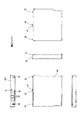
図1は、本発明の実施の形態による携帯通信端末の一例を示した外観図であり、携帯情報端末の一例として携帯電話機1が示されている。この携帯電話機1は、いわゆる折り畳み式の携帯電話機であり、表示筐体100及び操作筐体200が、ヒンジ部300を介して連結され、表示筐体100及び操作筐体200の一面を対向させて折り畳むことができる。表示筐体100及び操作筐体200は、いずれも略長方形の薄型筐体からなり、コンパクトに折り畳んで携帯することができる。
FIG. 1 is an external view showing an example of a mobile communication terminal according to an embodiment of the present invention. A
表示筐体100は、折り畳み時に内側となる内側主面にメイン表示部101及び受話用レシーバ102が配置され、外側となる外側主面にサブ表示部103が配置されている。また、操作筐体200は、折り畳み時に内側となる内側主面に多数の操作キー201及び送話用マイクロフォン202が配置されている。従って、両筐体を展開させれば、メイン表示部101の表示を見ながら、操作キー201を押下操作することができる。
In the
図2〜図4は、図1の操作筐体200の外観を示した斜視図であり、折り畳み時に外側となる操作筐体200の外側主面が示されている。図2には、蓋体204を取り外した状態、図3には、電池パック4を取り出した状態、図4には、電池パック4及びSIMカード5を取り出した状態がそれぞれ示されている。また、図5及び図6は、電池パック4の外形を示した斜視図及び正投影図、図7は、SIMカード5の外形を示した図である。
2 to 4 are perspective views showing the outer appearance of the operation casing 200 of FIG. 1, and show the outer main surface of the operation casing 200 that is the outer side when folded. 2 shows a state where the
まず、操作筐体200及び蓋体204について説明する(図2を参照)。操作筐体200の外側主面には、カメラ203及び蓋体204がそれぞれ配置されている。蓋体204は、電池装着口401を閉鎖するための部品であり、操作筐体200の外側主面の一部を構成している。蓋体204は容易に着脱することができ、蓋体204を操作筐体200から取り外すと、電池パック4を着脱するための電池装着口401が現れる。この電池装着口401を介して、ユーザは装着中の電池パック4の上面と、切欠部51を含むSIMカード5の後端とを視認することができ、SIMカード5が正しく装着されていることを目視にて確認することができる。
First, the
次に、電池パック4について説明する(図5及び図6を参照)。電池パック4は、略矩形の平板形状からなる電池筐体40を有し、カード挿入口501に対向する端面40e上に、1つの誤装着防止突起41と、3つの固定用突起42と、3つの電極端子43とが設けられている。
Next, the
電池筐体40は、容易に変形しない樹脂などの硬質材料からなり、リチウムイオン電池などの二次電池を内蔵している。誤装着防止突起41は、正しく装着されたSIMカード5の切欠部51に対向する位置に形成された凸部である。この例では、端面40eの中央付近の上面に近い位置に形成されている。固定用突起42は、電池収容部400の内壁に形成された固定用孔411に係合させることにより、電池パック4を電池収容部400内で位置決めする係合手段である。この例では、テーパー状の側面を有する錐台形状からなる3個の固定用突起42が、上記端面40eの中央付近及び両端付近の下面に近い位置に形成されている。電極端子43は、電池収容部400の内壁に形成されたスプリング端子412と導通させる端子である。
The
次に、SIMカード5について説明する(図7を参照)。SIMカード5は、略長方形の4つの頂点の1つだけを切り欠いて直線的に傾斜する切欠部51が形成されたカードであり、電池パック4よりも薄いシート形状内に、加入者識別情報を保持している不揮発性半導体素子が内蔵されている。また、その一方の主面上に携帯電話機と導通させるための複数の電極端子52が形成されている。当該電極端子52は、切欠部51が形成されていない短辺付近、つまり、長手方向に関し、切欠部51とは反対側に形成されている。
Next, the
次に、電池収容部400について説明する(図3を参照)。電池収容部400は、操作筐体200の外側主面に形成された凹部であり、操作筐体200と平行になるように電池パック4を収容することができる。電池収容部400のSIMカード5側の壁面410には、カード挿入口501、固定用孔411及びスプリング端子412が設けられている。
Next, the
カード挿入口501は、SIMカード5を挿入するための細長い孔であり、操作筐体200と平行に直線的に延びる形状を有している。固定用孔411は、電池パック4の固定用突起42を挿入するための係合手段であり、壁面410の中央付近及び両端付近の底面に隣接する位置に形成されている。スプリング端子412は、電池パック4の電極端子43と弾性的に接触させ、携帯電話機本体と電池パック4とを電気的に導通させるための端子である。
The
次に、カード収容部500について説明する(図4を参照)。カード収容部500は、SIMカード5を収容するスロットイン方式のカード保持手段である。SIMカード5は、その長手方向が挿入方向となるように、カード挿入口501に挿入される。カード挿入口501の下方には、電池収容部400の壁面410をSIMカード5の挿入方向へ傾斜させた傾斜面502が形成されており、SIMカード5の挿入を容易化している。また、カード挿入口501の上方には、上記傾斜面502とともにカード挿入口501を構成する縁部510及び511が形成されている。
Next, the
カード露出部512は、SIMカード5の上面をより大きく露出させるために、上記縁部の一部をカード挿入方向に後退させて形成されている。図4では、上方中央の縁部511のみを後退させて、カード露出部512を形成している。SIMカード5の取り外しは、カード挿入口501からはみ出しているSIMカード5の後端を摘むか、あるいは、後端を指で抑えながら、SIMカード5を引き出すことによって行われる。このため、カード露出部512を設けることによって、SIMカードの装着状態が視認しやすくなるとともに、SIMカード5の取り出しを容易化することができる。一方、後退させていない残りの縁部、すなわち、上方両端の縁部510は、SIMカード5をしっかりと保持し、SIMカード5が斜め上方に引き出されたり、あるいは、斜め上方から挿入されるのを防止している。
The
カード収容部500内には、図示しないスプリング電極が下面の奥側に形成されている。このため、SIMカード5の電極端子52と、上記スプリング端子とを導通させるためには、電極端子52の形成面を下に向けて、切欠部51が後端となるように挿入する必要がある。つまり、SIMカード5は、カードの向きが予め定められた装着方向となるように挿入しなければならない。
In the
一般に、スロットイン方式のカード収容部500は、トレイ方式に比べて、カード収容部を小型化、薄型化することができるというメリットがある一方、SIMカードを反転又は回転させて挿入できてしまうというデメリットがある。しかしながら、この携帯電話機1の場合、装着方向が誤っていれば、カード装着中の切欠部51の位置が変化し、その後に電池パック4を挿入することができなくなる。しかも、切欠部51及び誤装着防止突起41の位置関係を視認することができる。このため、SIMカード5の装着方法について予備知識を有しないユーザであっても、SIMカード5の装着方向が誤っていれば、そのことを直感的に理解し、かつ、正しい装着方向を直ちに理解することができる。
In general, the slot-in type
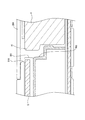
図8は、操作筐体200を図2のA−A切断線によって切断したときの様子を示した断面図である。この携帯電話機1の場合、カード挿入口501の縁部510及び511は、電池装着口401の縁部でもあり、操作筐体200を利用してカード挿入口501が形成されている。
FIG. 8 is a cross-sectional view showing a state when the
SIMカード5は、電池パック4の上面よりも底面側に配置されている。このため、電池パック4の装着中は、SIMカード5を引き出すことができない。つまり、電池パック4をSIMカード5のストッパーとして機能させている。
The
また、電池パック4の誤装着防止突起41の高さは、SIMカード5の厚さよりも十分に大きく、SIMカード5の後端と、誤装着防止突起41とが対向するように配置されている。従って、SIMカード5が誤った方向に装着されている場合には、SIMカード5と、電池パック4の誤装着検出部41とが干渉して、電池パック4を装着することができないようになっている。
Further, the height of the erroneous mounting
電池パック4は、SIMカード5や、カード挿入口の縁部510との間に所定のクリアランスが設けられている。電池パック4は、電池収容部400への着脱時に、固定用突起42が形成されている端面40e側が下がるように傾ける必要がある。従って、SIMカード5側の電池パック4の周辺には所定のクリアランスを設けておく必要がある。ただし、上記クリアランスは、SIMカード5を斜め上方に引き出したり、斜め上方から挿入したりすることはできない程度の隙間となっている。例えば、後退させていないカード挿入口の縁部510と、電池パック4の誤挿入検出突起41とのクリアランスが、SIMカードを着脱できない長さに調整されている。特に、SIMカード5が可撓性を有している場合であっても、電池パック4の装着中に、SIMカード5を着脱できないように構成されていることが望ましい。
The
図9は、ユーザが行う可能性があるSIMカードの装着状態を示した図である。図中の(a)は、SIMカード5が正しく装着された場合が示されている。切欠部51によって形成された空間に電池パック4の誤装着防止突起41を進入させることによって、電池パック4を電池収容部400に装着することができる。(b)〜(d)はいずれもSIMカード5が正しく装着されていない場合が示されている。(b)には、(a)のSIMカード5の表裏を反転させて装着した場合、(c)には、(a)のSIMカード5を180度回転させて装着した場合、(d)には、(a)のSIMカード5を反転させ、さらに180度回転させて装着した場合がそれぞれ示されている。いずれの場合も、切欠部51の位置が(a)の場合とは異なっており、電池パック4を電池収容部400に装着することはできない。
FIG. 9 is a diagram illustrating a state where a SIM card may be mounted by the user. (A) in the figure shows a case where the
本実施の形態による携帯電話機1は、薄型の操作筐体200内において、電池パック4及びSIMカード5を重複させることなく配置している。このため、操作筐体200を更に薄型化することができる。
In the
また、SIMカード5を挿入するカード挿入口501を電池収容部400の壁面410に形成し、電池パック4の端面40eと対向させている。このため、電池パック4がSIMカード5のストッパーとして機能し、電池パック4を取り外した状態でなければ、SIMカード5を着脱することができない。その結果、携帯電話機1の電源投入中に、ユーザがSIMカード5を装着したり、取り外したりするのを防止することができる。
Further, a
さらに、SIMカード5の切欠部51に対応する誤装着防止突起41を電池パック4に設け、SIMカード5を誤って装着すれば、SIMカード5と誤装着防止突起41とが干渉し、電池パック4を装着することができない。このため、何ら予備知識を有しないユーザであっても、SIMカード5の誤装着であることを直ちに理解することができ、携帯電話機1の故障であると勘違いすることがない。しかも、正しい装着方向も容易に推測することができる。
Furthermore, if the
また、電池パック4の誤装着防止突起41によって、SIMカード5の誤装着を防止することができるため、トレー方式に比べて、小型軽量化に有利なスロットイン方式のカード収容部500を採用することができ、操作筐体200の更なる薄型化を実現することができる。
In addition, since the erroneous mounting
なお、本実施の形態において、携帯通信端末の一例として説明した携帯電話機は、特に薄型化の要請が強い装置であり、本発明の適用対象として好適であるが、本発明は、携帯電話機には限定されない。すなわち、端末筐体の薄型化が求められている様々な携帯通信端末に本発明を適用することができる。 Note that the mobile phone described as an example of the mobile communication terminal in this embodiment is a device that is particularly demanded to be thin, and is suitable as an application target of the present invention. It is not limited. That is, the present invention can be applied to various portable communication terminals for which a thin terminal casing is required.
また、本発明では、SIMカード5を着脱する例について説明したが、本発明は、このような場合には限定されない。すなわち、携帯通信端末への着脱が可能な種々のメモリカードにも適用することができる。
In the present invention, the example in which the
4 電池パック
5 SIMカード
40 電池筐体
40e 端面
41 誤装着防止突起
42 固定用突起
43 電極端子
51 切欠部
52 電極端子
100 表示筐体
200 操作筐体
204 蓋体
300 ヒンジ部
400 電池収容部
401 電池装着口
410 壁面
411 固定用孔
412 スプリング端子
500 カード収容部
501 カード挿入口
502 傾斜面
510,511 縁部
512 カード露出部
4
Claims (3)
上記薄型筐体の主面上に形成された電池装着口を介して装着される上記電池パックを収容する電池収容部と、
上記電池パックと重複させることなく上記メモリカードを収容するカード収容部と、
上記電池パックの端面と対向する上記電池収容部の壁面に形成され、上記メモリカードの後端を押圧することにより上記メモリカードを上記カード収容部へ挿入するためのカード挿入口とを備え、
上記メモリカードは、上記カード収容部への装着方向を識別するための切欠部を有し、上記切欠部を含む端辺が後端となるように上記カード挿入口から挿入され、
上記電池パックは、上記カード挿入口に対向する端面に上記メモリカードの切欠部に対応する誤装着防止突起が形成されており、
上記カード挿入口は、上記電池装着口側の縁部の一部を後退させることにより、上記電池パックの非装着時に上記メモリカードを抜き出し可能とし、上記電池パックの装着時に上記メモリカードを抜き出し不可能となることを特徴とする携帯通信端末。 In a portable communication terminal consisting of a thin casing that detachably incorporates a thin battery pack and a memory card,
A battery housing portion for housing the battery pack mounted via a battery mounting opening formed on the main surface of the thin casing;
A card accommodating portion for accommodating the memory card without overlapping with the battery pack;
A card insertion slot formed on the wall surface of the battery housing portion facing the end surface of the battery pack, and for inserting the memory card into the card housing portion by pressing the rear end of the memory card;
The memory card has a notch for identifying the mounting direction to the card accommodating portion, and is inserted from the card insertion slot so that an end side including the notch becomes a rear end,
The battery pack has a mis-mounting prevention protrusion corresponding to the notch of the memory card formed on an end surface facing the card insertion slot ,
The card insertion slot allows the memory card to be removed when the battery pack is not installed by retracting a part of the edge on the battery insertion slot side, and the memory card cannot be removed when the battery pack is installed. A portable communication terminal characterized by being made possible .
Priority Applications (1)
| Application Number | Priority Date | Filing Date | Title |
|---|---|---|---|
| JP2007337341A JP4797016B2 (en) | 2007-12-27 | 2007-12-27 | Mobile communication terminal |
Applications Claiming Priority (1)
| Application Number | Priority Date | Filing Date | Title |
|---|---|---|---|
| JP2007337341A JP4797016B2 (en) | 2007-12-27 | 2007-12-27 | Mobile communication terminal |
Publications (2)
| Publication Number | Publication Date |
|---|---|
| JP2009159471A JP2009159471A (en) | 2009-07-16 |
| JP4797016B2 true JP4797016B2 (en) | 2011-10-19 |
Family
ID=40962943
Family Applications (1)
| Application Number | Title | Priority Date | Filing Date |
|---|---|---|---|
| JP2007337341A Expired - Fee Related JP4797016B2 (en) | 2007-12-27 | 2007-12-27 | Mobile communication terminal |
Country Status (1)
| Country | Link |
|---|---|
| JP (1) | JP4797016B2 (en) |
Families Citing this family (5)
| Publication number | Priority date | Publication date | Assignee | Title |
|---|---|---|---|---|
| JP5039935B2 (en) * | 2008-02-13 | 2012-10-03 | エスアイアイ移動通信株式会社 | Portable communication device |
| JP2011166244A (en) * | 2010-02-05 | 2011-08-25 | Nec Casio Mobile Communications Ltd | Battery and enclosure of card type apparatus, and electronic apparatus |
| JP5785387B2 (en) * | 2010-11-26 | 2015-09-30 | 京セラ株式会社 | Electronics |
| JP5294429B2 (en) * | 2011-03-30 | 2013-09-18 | パナソニック株式会社 | Electronics |
| JP5902588B2 (en) * | 2012-08-22 | 2016-04-13 | 京セラ株式会社 | Portable information equipment |
Family Cites Families (2)
| Publication number | Priority date | Publication date | Assignee | Title |
|---|---|---|---|---|
| JP3637006B2 (en) * | 2001-07-30 | 2005-04-06 | 埼玉日本電気株式会社 | IC card slot locking mechanism and portable device equipped with the locking mechanism |
| JP4811369B2 (en) * | 2007-08-01 | 2011-11-09 | 日本電気株式会社 | Portable electronic devices |
-
2007
- 2007-12-27 JP JP2007337341A patent/JP4797016B2/en not_active Expired - Fee Related
Also Published As
| Publication number | Publication date |
|---|---|
| JP2009159471A (en) | 2009-07-16 |
Similar Documents
| Publication | Publication Date | Title |
|---|---|---|
| JP3160044U (en) | Power supply device | |
| US8421405B2 (en) | Charge system, mobile electronic device, cell terminal used for them, and secondary cell | |
| JP4797016B2 (en) | Mobile communication terminal | |
| JP4811369B2 (en) | Portable electronic devices | |
| JP4306143B2 (en) | Mobile phone | |
| TWI309482B (en) | ||
| WO2006093294A1 (en) | Card connector and electronic apparatus | |
| EP0694980A2 (en) | Battery pack and connection mechanism | |
| JP2004126877A (en) | Card holding structure | |
| JP2007109036A (en) | Mobile communication terminal device | |
| WO2004004292A1 (en) | Cell phone | |
| JP4454285B2 (en) | Function expansion card | |
| JP2008011275A (en) | Data communication apparatus | |
| JP2008288151A (en) | Waterproofing terminal structure | |
| JP4021797B2 (en) | Mobile terminal device | |
| JP5294429B2 (en) | Electronics | |
| TWI343687B (en) | ||
| KR200375089Y1 (en) | Case of portable information terminal | |
| JP4930355B2 (en) | Electronics | |
| JP2008263433A (en) | Electronic device | |
| JP2011244156A (en) | Portable terminal | |
| JP4539490B2 (en) | SIM card holding structure and portable terminal device | |
| JP4662884B2 (en) | Card storage structure and electronic device | |
| JP3103684U (en) | Stacked connector of micro type memory card and user identification module | |
| JP2001216481A (en) | Ic memory card and electric equipment using the same |
Legal Events
| Date | Code | Title | Description |
|---|---|---|---|
| A621 | Written request for application examination |
Free format text: JAPANESE INTERMEDIATE CODE: A621 Effective date: 20100218 |
|
| A977 | Report on retrieval |
Free format text: JAPANESE INTERMEDIATE CODE: A971007 Effective date: 20110411 |
|
| A131 | Notification of reasons for refusal |
Free format text: JAPANESE INTERMEDIATE CODE: A131 Effective date: 20110426 |
|
| A521 | Written amendment |
Free format text: JAPANESE INTERMEDIATE CODE: A523 Effective date: 20110610 |
|
| TRDD | Decision of grant or rejection written | ||
| A01 | Written decision to grant a patent or to grant a registration (utility model) |
Free format text: JAPANESE INTERMEDIATE CODE: A01 Effective date: 20110712 |
|
| A01 | Written decision to grant a patent or to grant a registration (utility model) |
Free format text: JAPANESE INTERMEDIATE CODE: A01 |
|
| A61 | First payment of annual fees (during grant procedure) |
Free format text: JAPANESE INTERMEDIATE CODE: A61 Effective date: 20110801 |
|
| R150 | Certificate of patent or registration of utility model |
Free format text: JAPANESE INTERMEDIATE CODE: R150 |
|
| FPAY | Renewal fee payment (event date is renewal date of database) |
Free format text: PAYMENT UNTIL: 20140805 Year of fee payment: 3 |
|
| LAPS | Cancellation because of no payment of annual fees |