JP4791319B2 - Inverter device, compressor drive device and refrigeration / air-conditioning device - Google Patents
Inverter device, compressor drive device and refrigeration / air-conditioning device Download PDFInfo
- Publication number
- JP4791319B2 JP4791319B2 JP2006279575A JP2006279575A JP4791319B2 JP 4791319 B2 JP4791319 B2 JP 4791319B2 JP 2006279575 A JP2006279575 A JP 2006279575A JP 2006279575 A JP2006279575 A JP 2006279575A JP 4791319 B2 JP4791319 B2 JP 4791319B2
- Authority
- JP
- Japan
- Prior art keywords
- motor
- phase difference
- acceleration
- current
- unit
- Prior art date
- Legal status (The legal status is an assumption and is not a legal conclusion. Google has not performed a legal analysis and makes no representation as to the accuracy of the status listed.)
- Expired - Fee Related
Links
Images


Landscapes
- Control Of Motors That Do Not Use Commutators (AREA)
Description
本発明は、モータを駆動するためのインバータ装置に関し、さらには、このインバータ装置により駆動される圧縮機駆動装置、および、このインバータ装置を搭載した冷凍装置、空調装置(これらを総称して冷凍・空調装置とする)に関する。 The present invention relates to an inverter device for driving a motor. Further, the present invention relates to a compressor driving device driven by the inverter device, a refrigeration device equipped with the inverter device, and an air conditioner (collectively referred to as refrigeration Air conditioner).
永久磁石同期モータは、保守性、制御性、耐環境性に優れており、高効率、高出力の運転が可能であるため広く利用されている。また、永久磁石を使用しない同期リラクタンスモータも安価でリサイクルが容易なモータとして盛に研究されている。 Permanent magnet synchronous motors are widely used because they have excellent maintainability, controllability, and environmental resistance, and can be operated with high efficiency and high output. Synchronous reluctance motors that do not use permanent magnets are also actively studied as inexpensive and easy-to-recycle motors.
永久磁石同期モータや同期リラクタンスモータ等の同期モータを高性能制御するためには、ロータの位置に応じた正弦波電流を流すことが重要となる。そのため、一般に、モータ制御装置には、ホール素子、エンコーダ、レゾルバ等のロータの位置を検出する位置センサを用いた自制運転(速度フィードバック運転)方法がある。また、位置センサに代えて、モータの電圧や電流の情報に基づいて、演算によって間接的にロータの位置を求める方法が開示されている。 In order to perform high-performance control of a synchronous motor such as a permanent magnet synchronous motor or a synchronous reluctance motor, it is important to flow a sine wave current according to the position of the rotor. Therefore, in general, the motor control device includes a self-limiting operation (speed feedback operation) method using a position sensor that detects the position of a rotor such as a hall element, an encoder, or a resolver. Moreover, it replaces with a position sensor and the method of calculating | requiring the position of a rotor indirectly by calculation based on the information of the voltage and electric current of a motor is disclosed.
しかし、位置センサの場合は、機器の小形化を妨げる大きな要因となるだけでなく、位置センサの信号を伝える複数本の配線や受信回路が必要となるため、信頼性、作業性、価格等で問題があった。また、モータの電圧や電流の情報に基づいて間接的にロータの位置を演算する方法の場合は、複雑かつ高速な演算処理が必要となるため、制御装置が高価になるという問題があった。 However, in the case of a position sensor, not only is it a major factor that hinders downsizing of the equipment, but it also requires multiple wires and receiving circuits to transmit the position sensor signal, so reliability, workability, cost, etc. There was a problem. In addition, in the method of indirectly calculating the position of the rotor based on information on the voltage and current of the motor, there is a problem that the control device becomes expensive because complicated and high-speed calculation processing is required.
上記問題を鑑み、位置情報に基づかず、速度指令のみに基づく他制運転(速度オープンループ運転)を行ない、モータ電圧とモータ電流の位相差を制御することにより高性能な正弦波駆動を実現する方法が特許文献1および特許文献2で開示されている。ここで、図5に基づいて、同期モータの電圧と電流との位相差によって制御する同期モータ駆動装置を説明する。
In view of the above problems, high-performance sine wave drive is realized by controlling the phase difference between motor voltage and motor current by performing other braking operation (speed open loop operation) based only on speed command, not based on position information The method is disclosed in
同期モータ駆動装置は、図5に示すように、ステータに3相のコイルやロータに永久磁石を備えた同期モータであるモータ1を駆動させるために、電力を供給するAC電源4と、交流電力と直流電力とを変換するインバータ回路2およびコンバータ回路3と、モータ電流を検出する電流センサ5と、検出したモータ電流を増幅およびオフセットを加算するモータ電流検出アンプ部6と、それらを制御するマイクロコンピュータBとから構成されている。なお、この電力を供給するAC電源4と、交流電力と直流電力とを変換するインバータ回路2およびコンバータ回路3とによってインバータ部Aが構成される。
As shown in FIG. 5, the synchronous motor driving device includes an
上記構成によると、AC電源4から供給された電力がインバータ回路2およびコンバータ回路3を介して交流電力に変換され、変換された交流電力がモータ1に供給されて、モータ1が駆動する。
According to the above configuration, the power supplied from the
電流センサ5は、モータ1のコイル端子U,V,Wの各相のうち、特定相(以下、U相とする)に流れるモータ電流を検出する。電流センサ5で検出されたモータ電流は、モータ電流検出アンプ部6に与えられ、所定量増幅およびオフセットを加算し、モータ電流信号が制御部7に与えられる。
The
マイクロコンピュータBは、位相差検出部8と、目標位相差情報格納部9と、加算器10と、PI演算部11と、回転数設定部12と、正弦波データテーブル13と、正弦波データ作成部14と、PWM作成部15とを備えており、夫々の処理は、各プログラムに沿って行なわれる。
The microcomputer B includes a phase
位相差検出部8は、モータ電流検出アンプ部6から与えられたモータ電流の信号を所定のタイミングでA/D変換して取込み、2個所のモータの駆動電圧位相を期間ごとにサンプリングした各電流サンプリングデータを積算してモータ電流信号面積を算出する。算出された2箇所のモータ電流信号面積の面積比を位相差情報として出力する。
The phase
目標位相差情報格納部9には、目標とする位相差情報が格納される。目標位相差情報と位相差情報との誤差データは、加算器10によって算出される。PI演算部11は、算出された誤差データに対して比例誤差データおよび積分誤差データを算出してデューティ基準値を出力する。なお、加算部10とPI演算部11とによって位相差制御部27が構成される。
The target phase difference
回転数設定部12は、同期モータ1の回転数指令を設定する。正弦波データテーブル13には、同期モータ1の所定の回転数に対応する正弦波データが格納される。正弦波データ作成部14は、同期モータ1の回転数指令と時間経過とに従って正弦波データテーブル13から同期モータのコイル端子U,V,Wの各相に対応した正弦波データを読出すとともに、U相の正弦波データに基づいてU相のモータ駆動電圧位相情報を出力する。
The rotation
PWM作成部15は、正弦波データとデューティ基準値とに基づいてPWM波形を作成し、作成したPWM波形をインバータ回路2の同期モータ端子U,V,W各相の駆動素子に出力する。
The PWM creation unit 15 creates a PWM waveform based on the sine wave data and the duty reference value, and outputs the created PWM waveform to the drive elements of the synchronous motor terminals U, V, and W of the
ところで、同期モータを目標速度まで加速させる場合において、位置情報に基づかず、速度指令のみに基づく他制運転で行なうと、モータトルクや負荷トルクに関係なく指令値通りの加速度で加速する。すなわち、通常の負荷より重い負荷がかかった場合においても、通常の負荷のときと同じ加速度で加速する。そのため、通常の負荷より重い負荷がかかった場合、通常のときと同じ加速度では、負荷によって通常のときと同様に加速することができない。そこで、必要なトルクを満足させるために、モータ電圧を大きくする必要がある。 By the way, when the synchronous motor is accelerated to the target speed, if it is carried out by other braking operation based only on the speed command without being based on the position information, it is accelerated at the acceleration according to the command value regardless of the motor torque or the load torque. That is, even when a load heavier than the normal load is applied, the vehicle accelerates at the same acceleration as that at the normal load. Therefore, when a load heavier than a normal load is applied, the acceleration cannot be accelerated by the load as in the normal case at the same acceleration as that in the normal case. Therefore, in order to satisfy the required torque, it is necessary to increase the motor voltage.
しかしながら、インバータ回路には、同期モータに供給できるモータ電圧に限界がある。そのため、モータ電圧が最大値となっても、なお加速する場合は、モータ電圧をそれ以上大きくすることができない。そのため、同期モータは、モータトルクが不足するので駆動が不安定となり、最悪の場合は脱調して運転不能に至る等の問題がある。 However, the inverter circuit has a limit on the motor voltage that can be supplied to the synchronous motor. Therefore, even if the motor voltage reaches the maximum value, the motor voltage cannot be increased any more when the motor voltage is accelerated. For this reason, the synchronous motor has an unstable driving because the motor torque is insufficient, and in the worst case, there is a problem that the step-out causes the operation to become impossible.
そこで、検出した位相差に閾値を設定し、デューティ基準値が調整範囲内で最大となっている状態の時に、位相差が閾値よりも小さくなった場合にはモータの加速を禁止することにより、脱調を未然に防止する方法が特許文献3で開示されている。
Therefore, by setting a threshold value for the detected phase difference and prohibiting the acceleration of the motor when the phase difference becomes smaller than the threshold value when the duty reference value is maximum within the adjustment range,
図6に示すように、高速時は、電流位相が大きくなり、弱め磁束領域でモータ駆動が行なえていることが分かる。ここで、例えば、位相差の閾値を5度と設定すると、最高回転数は、約4700rpmで制限され、脱調にいたる危険性を回避できる。
しかしながら、回転数−位相差特性は、図7に示すように、負荷の大小により変化するため、加速を禁止する位相差の閾値を一意に設定すると、負荷が変化した場合に種々問題が発生する。例えば、閾値を15度と設定すると、脱調にいたる危険性は負荷の大小に関わらず回避できるが、負荷が中あるいは小のときの最高回転数が低くなり、同期モータの性能を十分に発揮できない問題が発生する。一方、負荷が小の場合の最高回転数を大きくするために閾値を−5度に設定すると、負荷が大および中において加速を禁止することができなくなり、脱調する問題が発生する。 However, since the rotational speed-phase difference characteristic changes depending on the load as shown in FIG. 7, if the phase difference threshold value for prohibiting acceleration is uniquely set, various problems occur when the load changes. . For example, if the threshold is set to 15 degrees, the risk of step-out can be avoided regardless of the load level, but the maximum number of revolutions when the load is medium or low is reduced, and the performance of the synchronous motor is fully demonstrated. Problems that can not be generated. On the other hand, if the threshold is set to −5 degrees in order to increase the maximum number of revolutions when the load is small, acceleration cannot be prohibited when the load is large and medium, causing a problem of step-out.
負荷によって閾値を変更することで上記課題を改善することができるが、その場合、負荷検出装置が必要となり、機器の小型化を妨げる大きな要因となるだけでなく、インバータ装置が高価となる問題が発生する。 The above problem can be improved by changing the threshold according to the load, but in that case, a load detection device is required, which is not only a major factor that hinders downsizing of the device, but also the problem that the inverter device becomes expensive. appear.
そこで、本発明は、簡単な構成と制御によって、安定した同期モータの運転を可能にする、安価かつ高性能なインバータ装置の提供を目的とする。 Therefore, an object of the present invention is to provide an inexpensive and high-performance inverter device that enables stable synchronous motor operation with a simple configuration and control.
上記目的を達成するために、本発明は、可変電圧、可変周波数を出力し、同期モータを可変速制御するインバータ装置であって、同期モータに電力を供給するインバータ部と、PWM制御方式によって前記インバータ部を他制運転制御する制御装置とを備え、前記制御装置は、前記インバータ部を流れる電流を検出する電流検出手段と、検出された前記電流からモータ電流とモータ電圧との位相差を検出する位相差検出手段と、前記位相差と目標とする目標位相差との差に応じてデューティ基準値を調整する調整手段と、前記位相差の変化から前記同期モータの加速を制御する加速手段と、前記同期モータの回転数指令値を設定する回転数設定手段と、前記回転数指令値に対応する出力波形データと調整された前記デューティ基準値とに基づいてPWM信号を算出するPWM信号作成手段とを有し、前記回転数設定手段は、前記加速手段の指令に応じて前記回転数指令値を変更することを特徴とする。 In order to achieve the above object, the present invention provides an inverter device that outputs a variable voltage and a variable frequency and controls a synchronous motor at a variable speed, the inverter unit supplying electric power to the synchronous motor, and the PWM control method. A control device that controls the inverter unit for other control operation, and the control device detects a phase difference between a motor current and a motor voltage from the detected current and a current detection unit that detects a current flowing through the inverter unit. A phase difference detecting means for adjusting, a adjusting means for adjusting a duty reference value in accordance with a difference between the phase difference and a target target phase difference, and an accelerating means for controlling acceleration of the synchronous motor from the change in the phase difference. A rotation speed setting means for setting a rotation speed command value of the synchronous motor, output waveform data corresponding to the rotation speed command value, and the adjusted duty reference value. And a PWM signal generating means for calculating a PWM signal Te, the revolution speed setting means, and changing the rotation speed command value according to a command of said accelerating means.
位相差を発生させることで同期モータは加速する。ところが、位相差が増加している状態で加速し続けると、同期モータはモータトルク不足となり、駆動が不安定となる。そこで、位相差の増減から加速が可能か不可能かを加速手段によって判定する。回転数設定手段は、判定結果に応じて回転数を設定する。そのため、同期モータの無理な加速を禁止し、同期モータの脱調を防止することができる。 The synchronous motor is accelerated by generating the phase difference. However, if the acceleration continues while the phase difference is increasing, the synchronous motor becomes insufficient in motor torque, and the driving becomes unstable. Therefore, the acceleration means determines whether acceleration is possible or not from the increase / decrease of the phase difference. The rotation speed setting means sets the rotation speed according to the determination result. Therefore, excessive acceleration of the synchronous motor can be prohibited, and the synchronous motor can be prevented from stepping out.
加速手段は、デューティ基準値がその調整範囲内で最大となっているときに、同期モータの加速を許可するか否かを判定することを特徴とする。デューティ基準値が調整範囲内で最大となっている状態において、回転を維持するのに必要なモータ駆動電圧が不足する場合は回転数が上昇しないようにする。具体的には、加速手段は、位相差が減少している場合は同期モータの加速を許可し、位相差が増加している場合は前記同期モータの加速を禁止する。 The acceleration means determines whether or not to permit acceleration of the synchronous motor when the duty reference value is maximum within the adjustment range. In a state where the duty reference value is maximum within the adjustment range, the rotation speed is prevented from increasing when the motor drive voltage necessary for maintaining the rotation is insufficient. Specifically, the acceleration means permits acceleration of the synchronous motor when the phase difference decreases, and prohibits acceleration of the synchronous motor when the phase difference increases.
また、加速手段は、加速を許可したとき、位相差の変化度合いに応じて前記同期モータの加速度が変化するように指令値を出力する。例えば、位相差が大の場合は、モータトルクが不足するまで余裕があるため、更なる加速が可能である。位相差が小の場合は、モータトルクが不足するまで余裕が無いため、加速を抑える。回転数設定手段は、加速手段からの指令値に基づいて回転数を決める。制御装置は、設定された回転数に基づいて同期モータを駆動する。そのため、同期モータを状況に応じて適切に加速制御することができ、目標回転数にスムーズに到達する。 The acceleration means outputs a command value so that the acceleration of the synchronous motor changes according to the change degree of the phase difference when the acceleration is permitted. For example, when the phase difference is large, there is a margin until the motor torque is insufficient, so that further acceleration is possible. When the phase difference is small, there is no room until the motor torque is insufficient, so acceleration is suppressed. The rotation speed setting means determines the rotation speed based on a command value from the acceleration means. The control device drives the synchronous motor based on the set rotation speed. Therefore, the synchronous motor can be appropriately accelerated and controlled according to the situation, and the target rotational speed can be reached smoothly.
電流検出手段としては、同期モータからインバータ部に流れるモータ電流を検出する第1電流検出手段と、インバータ部を流れる直流電流を検出する第2電流検出手段と、インバータ部を流れるモータ電流の極性を検出する第3電流検出手段とがあり、いずれか1つを採用する。 The current detection means includes first current detection means for detecting motor current flowing from the synchronous motor to the inverter unit, second current detection means for detecting DC current flowing through the inverter unit, and polarity of the motor current flowing through the inverter unit. There is a third current detection means to detect, and any one is adopted.
以上のように、本発明によれば、インバータ装置が供給できるモータ電圧の最大値に達した後でも、無理なく同期モータが加速することができ、同期モータの加速時の脱調を防止し、安定した制御をすることができる信頼性の高いインバータ装置を得ることができる。 As described above, according to the present invention, even after reaching the maximum value of the motor voltage that can be supplied by the inverter device, the synchronous motor can be accelerated without difficulty, preventing the step-out during the acceleration of the synchronous motor, A highly reliable inverter device capable of stable control can be obtained.
[第1実施形態]
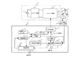
以下、本発明の第1実施形態を図1に基づいて説明する。本発明のモータ駆動用のインバータ装置は、図1に示すように、3相の同期モータであるモータ1がインバータ回路2の出力側に接続されており、インバータ制御によって駆動される。インバータ回路2には、コンバータ回路3によってAC電源4からの交流電圧が直流電圧に変換されて供給される。
[First Embodiment]
A first embodiment of the present invention will be described below with reference to FIG. In the inverter apparatus for driving a motor according to the present invention, as shown in FIG. 1, a
インバータ回路2とモータ1とを結ぶモータ1のコイル端子U,V,Wの各相のうち、特定相(以下、U相とする)に電流センサ5が設けられる。電流センサ5で検出されたモータ電流は、モータ電流検出アンプ部6に出力される。モータ電流検出アンプ部6は、制御装置としてのマイクロコンピュータBに接続され、所定量増幅およびオフセットを加算し、モータ電流信号としてマイクロコンピュータBに出力する。なお、この電流センサ5とモータ電流検出アンプ部6とが、インバータ部Aに流れる電流を検出する電流検出手段とされる。
A
マイクロコンピュータBは、位相差検出部8と、目標位相差情報格納部9と、加算器10と、PI演算部11と、回転数設定部12と、正弦波データテーブル13と、正弦波データ作成部14と、PWM作成部15と、加速判定部16とを有し、各処理をプログラムにしたがってソフト的に行なう。
The microcomputer B includes a phase
位相差検出部8は、モータ電流検出アンプ部6により出力されたモータ電流信号を用いてモータ電圧信号の位相差を検出する。なお、モータ1のモータ電圧信号は、マイクロコンピュータBで作成するため、モータ電圧信号を直接検出する必要はなく、ソフト的に検出可能である。また、検出する位相差情報は、モータ電圧がモータ電流に対して進み位相の場合は正の値、遅れ位相の場合は負の値、同相の場合は0とする。なお、この位相差検出部8が位相差検出手段とされる。
The phase
目標位相差情報格納部9は、目標とする位相差情報を格納し、加算器10は、その目標位相差情報と位相差検出部8から出力された位相差情報との誤差データを算出し、その算出結果をPI演算部11に出力する。PI演算部11は、算出された誤差データに対して比例誤差データ(P)および積分誤差データ(I)を算出し、デューティ基準値をPWM作成部15に出力する。なお、この目標位相差情報格納部9と加算器10とPI演算部11とが、検出された位相差情報と目標とする目標位相差情報との誤差に応じてデューティ基準値を調整する調整手段とされる。
The target phase difference
回転数設定部12は、目標とする回転数指令値を格納しており、その格納された回転数指令値から所定の回転数を設定して正弦波データ作成部14に出力する。なお、この回転数設定部12が回転数設定手段とされる。
The rotational
正弦波データテーブル13は、所定のデータ個数で構成された正弦波データを予め記憶しており、正弦波データを正弦波データ作成部14に出力する。正弦波データ作成部14は、回転数設定部12の設定した回転数指令値と、正弦波データテーブル13とからモータ巻線端子U,V,Wの各相に対応した正弦波データを読出して、PWM作成部15に出力するとともに、U相の正弦波データからU相のモータ駆動電圧位相情報を位相差検出部8に出力する。なお、この正弦波データテーブル13と正弦波データ作成部14とが周波数補正手段とされる。
The sine wave data table 13 stores in advance sine wave data composed of a predetermined number of data, and outputs the sine wave data to the sine wave data creation unit 14. The sine wave data creation unit 14 reads out the sine wave data corresponding to each phase of the motor winding terminals U, V, and W from the rotation speed command value set by the rotation
PWM作成部15は、正弦波データとデューティ基準値とから各相のインバータ回路2の各駆動素子にモータ駆動電圧であるPWM波形信号を出力する。この正弦波データの作成は、正弦波データテーブル13を元に作成することに限られず、例えば、演算によって作成しても構わない。なお、このPWM作成部15がPWM作成手段とされる。
The PWM generator 15 outputs a PWM waveform signal, which is a motor drive voltage, to each drive element of the
加算器10は、位相差検出部8から出力された位相差情報と目標位相差情報との誤差量を求め、PI演算部11では、P制御によって誤差量に対して所定の増幅を行ない、比例誤差量を算出し、I制御によって誤差量を積算して、その値を増幅して積分誤差量を算出し、両者を加算してデューティ基準値を算出する。このデューティ基準値と別途回転数指令値から求まる正弦波データとに基づいてPWM作成部15がその都度の出力デューティを計算し、インバータ部2を介してモータ巻線に印加することによってモータ1が駆動される。
The
すなわち、モータ駆動電圧(出力デューティ)に対するモータ巻線電流位相差を一定に制御するための位相差制御フィードバックループによって、駆動電圧の大きさ(PWMデューティのデューティ幅)が決定される。また、モータ1を所望の回転数で回転させるために、所望の周波数で出力される正弦波データによって回転数が決定される。これによって、所望の位相差、所望の回転数でモータ1を駆動制御できる。すなわち、モータ1のロータ位置を検出する位置センサを設けなくても、モータ1の駆動が可能となり、モータ効率の向上、低騒音および低振動を簡単な構成と制御で実現できる。
That is, the magnitude of the drive voltage (duty width of the PWM duty) is determined by the phase difference control feedback loop for controlling the motor winding current phase difference with respect to the motor drive voltage (output duty) to be constant. Further, in order to rotate the
しかし、インバータ回路2がモータ1に供給できるモータ電圧には上限がある。そのため、モータ1の加速時の制御においては、インバータ回路2が供給できるモータ電圧が最大値となっても目標回転数に達しない場合がある。その場合は、目標回転数に達するためにさらにモータ1が加速すると、実際の位相差を目標位相差に対して一定の位相差となるように制御することは不可能となる。そのため、モータ1が加速するほど、モータ電流とモータ電圧の位相差は小となり、目標の位相差と検出された位相差との差が生じる。このような状態でさらにモータ1を加速すると加速度が大きくなる。それにより、モータ1はモータトルク不足となり、駆動が不安定となって、最悪の場合は脱調して運転不能となる。
However, there is an upper limit to the motor voltage that the
そこで、本発明は、図1に示すように、位相差検出部8から出力された位相差情報と回転数設定部12で設定した回転数指令値に基づいて、モータ1の加速を許可するか否かを判定する加速手段を設ける。加速手段は、位相差情報の変化と回転数指令値の変化からモータ1の状況を判断し、モータ1の状況に応じて加速を許可するか否かを判定する加速判定部16である。
Therefore, as shown in FIG. 1, the present invention permits acceleration of the
加速判定部16は、所定のタイミング、例えば、1秒毎に、位相差検出部8から出力された位相差情報と回転数設定部12で設定した回転数指令値を受信する。指令回転数から加速しているか否かを判断し、加速している場合は、位相差情報から位相差が増加しているか減少しているかを判断する。位相差が増加している場合、すなわち、図6に示すYの状態の場合、モータトルク不足となる回転数までの余裕が少ないため更なる加速を禁止する。位相差が減少している場合、すなわち、図6に示すXの状態の場合、モータトルク不足となる回転数まで余裕があるため更なる加速を許可する。加速判定部16は、この判定結果を回転数設定部12に出力する。回転数設定部12は、加速を許可された場合、目標回転数に達するまで加速を維持する。加速を禁止された場合は、加速を止め、加速判定部16が判定したときの回転数を維持する。
The acceleration determination unit 16 receives the phase difference information output from the phase
具体的な加速判定部の判定動作を、図2に基づいて説明する。なお、説明の便宜上、デューティ基準値が調整範囲内で最大となっている状態の回転数と位相情報を用いて説明する。 A specific determination operation of the acceleration determination unit will be described with reference to FIG. For convenience of explanation, description will be made using the rotation speed and phase information in a state where the duty reference value is maximum within the adjustment range.
加速判定部16は、デューティ基準値が最大であるか否かを判定する(S1)。最大でない場合は、加速が可能と判定し(S9)、その判定結果を回転数設定部12に出力する。
The acceleration determination unit 16 determines whether or not the duty reference value is maximum (S1). If it is not the maximum, it is determined that acceleration is possible (S9), and the determination result is output to the rotation
デューティ基準値が最大である場合は、現在の回転数指令値Knを抽出して記憶し(S2)、さらに、現在の位相差情報θnを抽出して記憶する(S3)。加速判定部16は、前回記憶した回転数指令値Kn−1を読み出し(S4)、現在の回転数指令値Knと比較し、加速中か否かを判定する(S5)。加速中でない場合は、加速が可能と判定し(S9)、その判定結果を回転数設定部12に出力する。
When the duty reference value is maximum, it extracts the current rotation speed command value K n stored (S2), further extracts and stores the current phase difference information θ n (S3). Acceleration determining unit 16 reads the rotation speed command value K n-1 which has been previously stored (S4), and compared with the current rotational speed command value K n, determines whether or not the acceleration (S5). If not accelerating, it is determined that acceleration is possible (S9), and the determination result is output to the rotation
加速中である場合、前回の位相差情報θn−1を読み出す(S6)。現在の位相差情報θnと比較し、位相差の変化を判定する(S7)。位相差の変化が減少の場合は、モータトルク不足となる回転数まで余裕があるため、更なる加速が可能と判定し(S9)、その判定結果を回転数設定部12に出力する。
If it is accelerating, the previous phase difference information θ n-1 is read (S6). Compared with the current phase difference information θ n , a change in phase difference is determined (S7). If the change in the phase difference is reduced, it is determined that further acceleration is possible since there is a margin for the rotational speed at which the motor torque is insufficient (S9), and the determination result is output to the rotational
位相差の変化が増加の場合は、モータトルク不足となる回転数までの余裕が少ないため、更なる加速が無理と判定し(S8)、その判定結果を回転数設定部12に出力する。
If the change in the phase difference is increased, there is little room until the rotational speed at which the motor torque is insufficient, so it is determined that further acceleration is impossible (S8), and the determination result is output to the rotational
次に、回転数の設定およびPWM出力について説明する。本発明による位相差制御方式は、逆起電圧パルスなどを検出して速度制御を行なう方式とは異なる。すなわち、モータ1の回転数は、モータ巻線に通電するPWM波からなる正弦波電圧の周波数で決定される、いわゆる強制励磁駆動である。
Next, setting of the rotation speed and PWM output will be described. The phase difference control method according to the present invention is different from the method in which the speed control is performed by detecting a counter electromotive voltage pulse or the like. That is, the rotation speed of the
回転数設定部12は、格納された回転数指令値から所定の回転数を設定して正弦波データ作成部14に出力する。正弦波データ作成部14では、回転数指令値に対応する正弦波データを正弦波データテーブル13から読み出し、その周波数指令値を回転数指令値と経過時間とに基づいて補正する。
The rotation
この時、回転数設定部12は、加速判定部16によって判定された加速の可否に対応した回転数指令値を設定する。加速判定部16は、マイクロコンピュータBのタイマ割り込み機能を利用して、所定時間毎に加速の可否判定処理を行ない、判定結果を回転数設定部12に出力する。
At this time, the rotation
回転数設定部12は、加速度推定部16の判定結果に応じて回転数指令値を決定し、制限はデータ作成部14に出力する。具体的には、加速が許可された場合、回転数設定部12は、現状の回転数よりさらに加速する回転数を回転数指令値として再設定し、設定された回転数指令値を正弦波データ作成部14に出力する。加速が禁止された場合、回転数設定部12は、これ以上の加速をしないように、現状の回転数を維持する回転数を回転数指令値として再設定し、正弦波データ作成部14に出力する。
The rotation
正弦波データテーブル13には、連続的にアナログ値を出力すると正弦波波形が出力されるデータ列が格納されている。このデータ列の参照アドレスがPWMキャリア周期ごとに所定数ずつ更新される。この所定数が大きければ高回転数となる。つまり、モータ回転数は、モータ1の構造的なものを除外すると、PWMキャリア周波数と正弦波データテーブル13の参照データとの更新間隔で決まる。例えば、巻線相数が3相であれば、それぞれの相のデータは、電気角で120度ずつにずらした正弦波データを参照すればよい。なお、その都度、正弦波演算を行って正弦波データを作成してもよい。
The sine wave data table 13 stores a data string in which a sine wave waveform is output when analog values are continuously output. The reference address of this data string is updated by a predetermined number every PWM carrier cycle. If this predetermined number is large, the rotation speed is high. That is, the motor rotation speed is determined by the update interval between the PWM carrier frequency and the reference data in the sine wave data table 13 except for the structural one of the
PWM波形発生器などのPWM作成部15において、これら求まった各相の正弦波データと位相差制御によって算出されたデューティ基準値とが乗算され、PWMデューティのデューティ幅が決定され、PWM波形信号がインバータ回路2の各駆動素子に出力される。このPWM波形発生器は、たとえばPWMキャリア周期で三角波を発生し、この三角波の波高値と前記乗算された値とを比較し、比較結果に基づいてHigh/Low信号を出力する。
In the PWM generator 15 such as a PWM waveform generator, the obtained sine wave data of each phase is multiplied by the duty reference value calculated by the phase difference control, the duty width of the PWM duty is determined, and the PWM waveform signal is obtained. It is output to each drive element of the
これにより、モータ電圧が最大値に達した後でも、十分な最高回転数を確保すると同時に、脱調の危険性を回避できる。また、十分な高速回転で駆動可能な高出力なインバータ装置を得ることができる。したがって、モータ加速時の脱調を防止して安定した制御をすることができ、信頼性も確保することができる。 Thereby, even after the motor voltage reaches the maximum value, a sufficient maximum number of revolutions can be ensured and at the same time the risk of step-out can be avoided. In addition, a high-power inverter device that can be driven at a sufficiently high speed rotation can be obtained. Therefore, stable control can be performed by preventing step-out during motor acceleration, and reliability can be ensured.
また、加速判定部16は、常に位相差検出部8から出力された位相差情報と回転数設定部12で設定した回転数指令値から加速可能か否かを判定している。そのため、図7に示すように、負荷の大小によりモータ1の駆動可能な最高回転数が変化する場合であっても対応することができる。
The acceleration determination unit 16 always determines whether acceleration is possible from the phase difference information output from the phase
[第2実施形態]
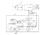
第2実施形態と第1実施形態とは、図3に示すように、モータ電流推定に関する手段が異なる。すなわち、第1実施形態では、モータ1の特定相に流れるモータ電流を電流センサ5によって検出しているが、第2実施形態は、コンバータ回路3とインバータ回路2とを流れる電流を検出する。
[Second Embodiment]
As shown in FIG. 3, the second embodiment and the first embodiment are different in means relating to motor current estimation. That is, in the first embodiment, the motor current flowing in the specific phase of the
以下、第1実施形態と異なる電流検出手段について説明する。なお、第2実施形態において、第1実施形態と同一の要素については、同一の符号を付して、その説明を省略する。 Hereinafter, current detection means different from the first embodiment will be described. Note that in the second embodiment, the same elements as those in the first embodiment are denoted by the same reference numerals, and description thereof is omitted.
第2実施形態は、図3に示すように、コンバータ回路3とインバータ回路2とを結ぶ直流回路の負極側に、電流検出抵抗21が設けられる。電流検出抵抗21の両端に発生する電圧に基づいて、直流電流検出アンプ部22がインバータ回路2を流れる直流電流を検出する。直流電流検出アンプ部22は、制御装置としてのマイクロコンピュータBに接続され、検出した直流電流を増幅して、直流電流信号としてマイクロコンピュータBに出力する。この直流電流検出アンプ部22が、インバータ回路2に流れる直流電流を検出する直流電流検出手段とされる。
In the second embodiment, as shown in FIG. 3, a
モータ電流推定部23は、入力された直流電流信号から電流変化分演算手段により直流電流の変化分を求め、直流電流信号の変化分を分配演算手段によりモータ電流信号を推定演算する。ここで、電流変化分演算手段および分配演算手段は、特開平8−19263号公報に記載されている。
The motor
これにより、コイルおよびホール素子で構成された電流センサ、カレントトランスといったモータ電流を検出するための電流センサを使用せずに、モータ電流を推定演算により検出することができるため、コストを削減することができる。 As a result, the motor current can be detected by estimation calculation without using a current sensor for detecting the motor current, such as a current sensor composed of a coil and a hall element, or a current transformer, thereby reducing costs. Can do.
[第3実施形態]
第3実施形態と第1実施形態とは、図4に示すように、モータ電流推定に関する手段が異なる。すなわち、第1実施形態では、モータ1の特定相に流れるモータ電流を電流センサ5によって検出しているが、第3実施形態は、インバータ部Aを流れるモータ電流の極性を検出する。
[Third Embodiment]
As shown in FIG. 4, the third embodiment and the first embodiment differ in the means relating to motor current estimation. That is, in the first embodiment, the motor current flowing in the specific phase of the
以下、第1実施形態と異なる電流検出手段について説明する。なお、第3実施形態において、第1実施形態と同一の要素については、同一の符号を付して、その説明を省略する。 Hereinafter, current detection means different from the first embodiment will be described. Note that in the third embodiment, identical symbols are assigned to elements that are the same as those in the first embodiment and descriptions thereof are omitted.
第3実施形態は、図4に示すように、インバータ回路2を流れる交流電流の極性を検出するモータ電流極性検出部31を備えている。モータ電流極性検出部31は、インバータ回路2において流れるモータ巻線端子U,V,Wの各相の交流電流極性を検出し、それらを論理合成して交流電流極性信号を形成すると、位相差検出部8に出力するようになっている。位相差検出部8は、モータ電流極性検出部31から出力された交流電流極性信号に基づいて、交流電流極性が反転した時点の交流電圧と交流電流との位相差を検出する。
As shown in FIG. 4, the third embodiment includes a motor current
これにより、電流極性情報のみからモータ電圧とモータ電流との位相差情報を検出することができるため、A/D変換機能を持たないマイクロコンピュータBを使用することができ、コストを削減することができる。 Thereby, since the phase difference information between the motor voltage and the motor current can be detected only from the current polarity information, the microcomputer B having no A / D conversion function can be used, and the cost can be reduced. it can.
ここで、冷凍・空調装置などで使用される圧縮機では、内部が高温状態になり、ホールICなどのロータ位置を検出する位置センサを設けることが困難であるため、位置センサレスでモータ1を駆動する必要がある。そこで、上記のインバータ装置を圧縮機駆動装置のモータを駆動するために使用する。これによって、コイルおよびホール素子で構成された電流センサ、カレントトランスといった交流電流を検出するための電流センサが不要となるとともに、位置センサも不要となる。そして、このインバータ装置を備えた圧縮機駆動装置を冷凍・空調装置に搭載する。これによって、冷蔵庫、冷凍庫、空気調和機といった冷凍・空調装置を運転することが可能となる。
Here, in a compressor used in a refrigeration / air conditioner or the like, the inside is in a high temperature state, and it is difficult to provide a position sensor for detecting the rotor position such as a Hall IC, so the
なお、本発明は、上記実施形態に限定されるものではなく、本発明の範囲内で上記実施形態に多くの修正および変更を加え得ることは勿論である。 In addition, this invention is not limited to the said embodiment, Of course, many corrections and changes can be added to the said embodiment within the scope of the present invention.
例えば、加速判定部は、加速の可否を判定すると同時に、加速が可能な場合においてどれぐらい加速が可能かを推定し、回転数設定部は、推定値から回転数指令値を設定しても良い。具体的には、加速判定部は、所定の位相差情報に基づいた加速度を格納した加速度選択テーブルを有する。加速判定部は、位相差情報と回転数指令値から加速の可否を判定すると同時に、位相差情報に基づいて加速度選択テーブルから所定の加速度を選択し、回転数設定部に出力する。回転数設定部は、加速が許可された場合、選択された加速度に基づいてさらに加速するような回転数とする回転数指令値を設定し、正弦波データ作成部に出力する。加速が禁止された場合、モータが加速しないような回転数とする回転数指令値を正弦波データ作成部に出力する。これにより、モータ1はモータトルク不足となり、駆動が不安定となって脱調することを防止することができる。
For example, the acceleration determination unit may determine whether acceleration is possible, and may estimate how much acceleration is possible when acceleration is possible, and the rotation speed setting unit may set the rotation speed command value from the estimated value. . Specifically, the acceleration determination unit has an acceleration selection table that stores accelerations based on predetermined phase difference information. The acceleration determination unit determines whether or not acceleration is possible from the phase difference information and the rotation speed command value, and at the same time, selects a predetermined acceleration from the acceleration selection table based on the phase difference information and outputs it to the rotation speed setting unit. When the acceleration is permitted, the rotational speed setting unit sets a rotational speed command value that makes the rotational speed further accelerated based on the selected acceleration, and outputs the rotational speed command value to the sine wave data creating unit. When acceleration is prohibited, a rotation speed command value that sets the rotation speed so that the motor does not accelerate is output to the sine wave data creation unit. As a result, the
また、本実施例において、U相位相差データは、特定相の位相差を検出しているが、特にこの限りではなく、V相、W相でもよい。また、本実施例における加速の可否判定は、図7に示すように、同期モータにかかる駆動可能な最高回転数が負荷の大小によって変化する場合に用いてもよい。 In this embodiment, the U-phase phase difference data detects a phase difference of a specific phase, but is not limited to this, and may be a V-phase or a W-phase. Further, the determination of whether or not acceleration is possible in the present embodiment may be used when the maximum rotational speed that can be driven by the synchronous motor varies depending on the magnitude of the load, as shown in FIG.
また、位相差の検出にはある程度の誤差が発生するため、位相差の変化の検出になんらかの平均化処理を追加しても良い。また、加速許可から加速禁止、あるいは加速禁止から加速許可へ変化する際には、なんらかのヒステリシス処理や時間待ち処理などを行なうことにより、頻繁な変化を回避しても良い。 Further, since a certain amount of error occurs in the detection of the phase difference, some averaging process may be added to the detection of the change in the phase difference. Further, when changing from acceleration permission to acceleration prohibition or from acceleration prohibition to acceleration permission, frequent changes may be avoided by performing some hysteresis processing or time waiting processing.
また、本実施例において本発明のインバータ装置を冷凍・空調装置等で使用される圧縮機のモータ駆動に用いているが、特にこれに限定されることはない。例えば、電車や電気自動車、エレベータ等の電気製品に用いてもよい。これにより、安定した駆動をすることができる。 Further, in the present embodiment, the inverter device of the present invention is used for driving a motor of a compressor used in a refrigeration / air conditioning device or the like, but is not particularly limited to this. For example, you may use for electric products, such as a train, an electric vehicle, and an elevator. Thereby, stable driving can be performed.
1 同期モータ
2 インバータ回路
3 コンバータ回路
4 AC電源
5 電流センサ
6 モータ電流検出アンプ部
8 位相差検出部
9 目標位相差情報格納部
10 加算器
11 PI演算部
12 回転数設定部
13 正弦波データテーブル
14 正弦波データ作成部
15 PWM作成部
16 加速判定部
21 電流検出抵抗
22 直流電流検出アンプ部
23 モータ電流推定部
31 モータ電流極性検出部
A インバータ部
B マイクロコンピュータ
DESCRIPTION OF
Claims (5)
前記制御装置は、前記インバータ部を流れる電流を検出する電流検出手段と、検出された前記電流からモータ電流とモータ電圧との位相差を検出する位相差検出手段と、前記位相差と目標とする目標位相差との差に応じてデューティ基準値を調整する調整手段と、前記位相差の変化から前記同期モータの加速を制御する加速手段と、前記同期モータの回転数指令値を設定する回転数設定手段と、前記回転数指令値に対応する出力波形データと調整された前記デューティ基準値とに基づいてPWM信号を算出するPWM信号作成手段とを有し、
前記回転数設定手段は、前記加速手段の指令に応じて前記回転数指令値を変更することを特徴とするインバータ装置。 An inverter device that outputs a variable voltage and a variable frequency to control a synchronous motor at a variable speed, and includes an inverter unit that supplies electric power to the synchronous motor, and a control device that controls the inverter unit in other control operations by a PWM control method Prepared,
The control device includes: current detection means for detecting a current flowing through the inverter unit; phase difference detection means for detecting a phase difference between a motor current and a motor voltage from the detected current; and the phase difference and a target. Adjustment means for adjusting the duty reference value according to the difference from the target phase difference, acceleration means for controlling the acceleration of the synchronous motor from the change in the phase difference, and the rotational speed for setting the rotational speed command value of the synchronous motor Setting means; PWM signal generation means for calculating a PWM signal based on the output waveform data corresponding to the rotation speed command value and the adjusted duty reference value;
The said rotation speed setting means changes the said rotation speed command value according to the command of the said acceleration means, The inverter apparatus characterized by the above-mentioned.
Priority Applications (1)
| Application Number | Priority Date | Filing Date | Title |
|---|---|---|---|
| JP2006279575A JP4791319B2 (en) | 2006-10-13 | 2006-10-13 | Inverter device, compressor drive device and refrigeration / air-conditioning device |
Applications Claiming Priority (1)
| Application Number | Priority Date | Filing Date | Title |
|---|---|---|---|
| JP2006279575A JP4791319B2 (en) | 2006-10-13 | 2006-10-13 | Inverter device, compressor drive device and refrigeration / air-conditioning device |
Publications (3)
| Publication Number | Publication Date |
|---|---|
| JP2008099467A JP2008099467A (en) | 2008-04-24 |
| JP2008099467A5 JP2008099467A5 (en) | 2009-05-14 |
| JP4791319B2 true JP4791319B2 (en) | 2011-10-12 |
Family
ID=39381714
Family Applications (1)
| Application Number | Title | Priority Date | Filing Date |
|---|---|---|---|
| JP2006279575A Expired - Fee Related JP4791319B2 (en) | 2006-10-13 | 2006-10-13 | Inverter device, compressor drive device and refrigeration / air-conditioning device |
Country Status (1)
| Country | Link |
|---|---|
| JP (1) | JP4791319B2 (en) |
Families Citing this family (5)
| Publication number | Priority date | Publication date | Assignee | Title |
|---|---|---|---|---|
| JP5195444B2 (en) * | 2009-01-14 | 2013-05-08 | パナソニック株式会社 | Brushless DC motor driving apparatus, refrigerator and air conditioner using the same |
| JP5556992B2 (en) | 2009-08-21 | 2014-07-23 | アイシン精機株式会社 | Motor control device and vehicle seat control device |
| JP6324323B2 (en) * | 2012-03-15 | 2018-05-16 | ボルグワーナー スウェーデン エービー | Electrical drive shaft device for road vehicles |
| KR101367678B1 (en) | 2012-07-31 | 2014-02-26 | 삼성전기주식회사 | Driving apparatus for motor |
| KR102459423B1 (en) * | 2020-09-10 | 2022-10-27 | 에스트라오토모티브시스템 주식회사 | Motor control method and system for reducing EMI in electric compressor of vehicle |
-
2006
- 2006-10-13 JP JP2006279575A patent/JP4791319B2/en not_active Expired - Fee Related
Also Published As
| Publication number | Publication date |
|---|---|
| JP2008099467A (en) | 2008-04-24 |
Similar Documents
| Publication | Publication Date | Title |
|---|---|---|
| Kim et al. | Commutation torque ripple reduction in a position sensorless brushless DC motor drive | |
| US9444377B2 (en) | Motor drive control device | |
| JP3888082B2 (en) | Motor device and control method thereof | |
| JP3684203B2 (en) | Motor control device | |
| JP5222640B2 (en) | Refrigeration equipment | |
| WO2012144276A1 (en) | Motor control device | |
| US7375482B2 (en) | Driving device of motor | |
| JP4791319B2 (en) | Inverter device, compressor drive device and refrigeration / air-conditioning device | |
| US11088646B2 (en) | Motor driving control device and motor driving control method | |
| JP3753074B2 (en) | DC brushless motor device | |
| JP4050489B2 (en) | Motor control method | |
| JP6463966B2 (en) | Motor driving device, motor driving module and refrigeration equipment | |
| JP2008172948A (en) | Controller for brushless motors | |
| JP2003199388A (en) | Motor driver | |
| JP2006149097A (en) | Motor controller | |
| JP2004147430A (en) | Sensorless drive control method and drive control system of electric motor | |
| JP5422435B2 (en) | Brushless motor driving apparatus and driving method | |
| JP4197974B2 (en) | Motor control device and motor control method | |
| JP2008148437A (en) | Controller for permanent magnet type synchronous motor | |
| JP2014007916A (en) | Motor control device | |
| JP2007151215A (en) | Inverter apparatus, compressor driver and refrigerator/air conditioner | |
| JP2011050170A (en) | Inverter device | |
| JP2000333465A (en) | Inverter apparatus, motor drive apparatus and motor drive system apparatus | |
| US20230142956A1 (en) | Motor controller, motor system and method for controlling motor | |
| JP2009011014A (en) | Inverter controller, electric compressor, and home electrical equipment |
Legal Events
| Date | Code | Title | Description |
|---|---|---|---|
| A521 | Written amendment |
Free format text: JAPANESE INTERMEDIATE CODE: A523 Effective date: 20090327 |
|
| A621 | Written request for application examination |
Free format text: JAPANESE INTERMEDIATE CODE: A621 Effective date: 20090327 |
|
| A977 | Report on retrieval |
Free format text: JAPANESE INTERMEDIATE CODE: A971007 Effective date: 20110531 |
|
| TRDD | Decision of grant or rejection written | ||
| A01 | Written decision to grant a patent or to grant a registration (utility model) |
Free format text: JAPANESE INTERMEDIATE CODE: A01 Effective date: 20110628 |
|
| A01 | Written decision to grant a patent or to grant a registration (utility model) |
Free format text: JAPANESE INTERMEDIATE CODE: A01 |
|
| A61 | First payment of annual fees (during grant procedure) |
Free format text: JAPANESE INTERMEDIATE CODE: A61 Effective date: 20110721 |
|
| FPAY | Renewal fee payment (event date is renewal date of database) |
Free format text: PAYMENT UNTIL: 20140729 Year of fee payment: 3 |
|
| R150 | Certificate of patent or registration of utility model |
Free format text: JAPANESE INTERMEDIATE CODE: R150 |
|
| LAPS | Cancellation because of no payment of annual fees |