JP4783018B2 - Method and apparatus for detecting and tracking the eye and its gaze direction - Google Patents
Method and apparatus for detecting and tracking the eye and its gaze direction Download PDFInfo
- Publication number
- JP4783018B2 JP4783018B2 JP2004553361A JP2004553361A JP4783018B2 JP 4783018 B2 JP4783018 B2 JP 4783018B2 JP 2004553361 A JP2004553361 A JP 2004553361A JP 2004553361 A JP2004553361 A JP 2004553361A JP 4783018 B2 JP4783018 B2 JP 4783018B2
- Authority
- JP
- Japan
- Prior art keywords
- eye
- image
- detector
- picture
- light
- Prior art date
- Legal status (The legal status is an assumption and is not a legal conclusion. Google has not performed a legal analysis and makes no representation as to the accuracy of the status listed.)
- Expired - Fee Related
Links
- 238000000034 method Methods 0.000 title description 27
- 230000000694 effects Effects 0.000 claims abstract description 18
- 238000001514 detection method Methods 0.000 claims abstract 23
- 238000011156 evaluation Methods 0.000 claims description 30
- 238000005286 illumination Methods 0.000 claims description 20
- 210000004087 cornea Anatomy 0.000 claims description 19
- 230000003287 optical effect Effects 0.000 claims description 15
- 210000003128 head Anatomy 0.000 claims description 9
- 210000001747 pupil Anatomy 0.000 abstract description 37
- 230000008901 benefit Effects 0.000 description 6
- 238000012545 processing Methods 0.000 description 5
- 210000001525 retina Anatomy 0.000 description 4
- 238000012986 modification Methods 0.000 description 3
- 230000004048 modification Effects 0.000 description 3
- 125000002066 L-histidyl group Chemical group [H]N1C([H])=NC(C([H])([H])[C@](C(=O)[*])([H])N([H])[H])=C1[H] 0.000 description 2
- 230000006399 behavior Effects 0.000 description 2
- 238000004891 communication Methods 0.000 description 2
- 230000004424 eye movement Effects 0.000 description 2
- 230000004418 eye rotation Effects 0.000 description 2
- 230000001939 inductive effect Effects 0.000 description 2
- 230000008447 perception Effects 0.000 description 2
- 238000011160 research Methods 0.000 description 2
- 230000002207 retinal effect Effects 0.000 description 2
- 238000005070 sampling Methods 0.000 description 2
- 230000007704 transition Effects 0.000 description 2
- 230000000007 visual effect Effects 0.000 description 2
- 208000013521 Visual disease Diseases 0.000 description 1
- 230000003542 behavioural effect Effects 0.000 description 1
- 230000005540 biological transmission Effects 0.000 description 1
- 239000003086 colorant Substances 0.000 description 1
- 238000010276 construction Methods 0.000 description 1
- 230000007423 decrease Effects 0.000 description 1
- 238000003745 diagnosis Methods 0.000 description 1
- 238000010586 diagram Methods 0.000 description 1
- 230000006870 function Effects 0.000 description 1
- 239000011521 glass Substances 0.000 description 1
- 230000004886 head movement Effects 0.000 description 1
- 230000002452 interceptive effect Effects 0.000 description 1
- 238000012544 monitoring process Methods 0.000 description 1
- 230000000704 physical effect Effects 0.000 description 1
- 210000003786 sclera Anatomy 0.000 description 1
- 238000004904 shortening Methods 0.000 description 1
- 235000015096 spirit Nutrition 0.000 description 1
- 208000029257 vision disease Diseases 0.000 description 1
- 230000004393 visual impairment Effects 0.000 description 1
Images


Classifications
-
- A—HUMAN NECESSITIES
- A61—MEDICAL OR VETERINARY SCIENCE; HYGIENE
- A61B—DIAGNOSIS; SURGERY; IDENTIFICATION
- A61B3/00—Apparatus for testing the eyes; Instruments for examining the eyes
- A61B3/10—Objective types, i.e. instruments for examining the eyes independent of the patients' perceptions or reactions
- A61B3/113—Objective types, i.e. instruments for examining the eyes independent of the patients' perceptions or reactions for determining or recording eye movement
-
- G—PHYSICS
- G06—COMPUTING; CALCULATING OR COUNTING
- G06V—IMAGE OR VIDEO RECOGNITION OR UNDERSTANDING
- G06V40/00—Recognition of biometric, human-related or animal-related patterns in image or video data
- G06V40/10—Human or animal bodies, e.g. vehicle occupants or pedestrians; Body parts, e.g. hands
- G06V40/18—Eye characteristics, e.g. of the iris
- G06V40/19—Sensors therefor
Landscapes
- Engineering & Computer Science (AREA)
- Health & Medical Sciences (AREA)
- Life Sciences & Earth Sciences (AREA)
- Human Computer Interaction (AREA)
- Physics & Mathematics (AREA)
- General Health & Medical Sciences (AREA)
- Ophthalmology & Optometry (AREA)
- Animal Behavior & Ethology (AREA)
- General Physics & Mathematics (AREA)
- Medical Informatics (AREA)
- Molecular Biology (AREA)
- Surgery (AREA)
- Biomedical Technology (AREA)
- Biophysics (AREA)
- Public Health (AREA)
- Veterinary Medicine (AREA)
- Heart & Thoracic Surgery (AREA)
- Multimedia (AREA)
- Theoretical Computer Science (AREA)
- Eye Examination Apparatus (AREA)
- Measurement Of The Respiration, Hearing Ability, Form, And Blood Characteristics Of Living Organisms (AREA)
- Burglar Alarm Systems (AREA)
- Focusing (AREA)
- Automatic Focus Adjustment (AREA)
Abstract
Description
(関連出願)
本出願はすべての教示内容が参照によって本明細書に組み込まれている、2002年11月21日に出願されたスウェーデン特許出願第0203457−7号の優先権と利益を主張するものである。
(Related application)
This application claims the priority and benefit of Swedish Patent Application No. 0203457-7, filed on Nov. 21, 2002, the entire teachings of which are incorporated herein by reference.
本発明は眼及び凝視角度/方向を検知し、かつ追跡するための方法と装置に関する。このようなシステムは例えばコンピュータのユーザが見ているモニタ又はディスプレー上の位置を確認、又は決定するために利用可能である。 The present invention relates to a method and apparatus for detecting and tracking eyes and gaze angles / directions. Such a system can be used, for example, to confirm or determine the position on a monitor or display that a computer user is viewing.
眼の動きと凝視点の監視又は追跡は異なる多くの状況で利用可能である。人が見ている位置に関する情報は、人の挙動と認識を分析するために利用可能である。これは人が見ている対象物の評価、及びそれぞれの人の評価の双方に利用できる。利用分野は多く、その中にはソフトウェアや異なる種類のインターフェースの利用可能性に関する研究;ホームページ、広告、宣伝の評価;シミュレータ環境でのパイロットを教育する手段;心理学、行動科学、人の知覚の調査;様々な種類の視覚障害や病気の診断を挙げることができる。 Eye movement and gaze monitoring or tracking can be used in many different situations. Information about the position a person is looking at can be used to analyze human behavior and perception. This can be used for both the evaluation of the object that the person is looking at and the evaluation of each person. There are many fields of use, including research on the availability of software and different types of interfaces; evaluation of homepages, advertisements and promotions; means of educating pilots in simulator environments; psychology, behavioral science, human perception Surveys: List the diagnosis of various types of visual impairments and diseases.
これらの用途に加えて、異なる態様で応答又は反応するために人が見ている場所に関する情報を用いる対話式の用途も存在する。例えば身体障害者は彼が見ているコンピュータのモニタ上の対象物が活動される手順によってコンピュータと対話することができる。アーケード・ゲームでは、人が見ている対象物が画像の中心に来るようにする手順、又は彼/彼女の眼を使って武器の方向を定めるようにできる手順によって、ゲームの冒険体験を極めて増強させることができる。同様に、店舗のウインドウ内のクリスマス向けの広告又はディスプレーは、人が見ていることに反応することができる。例えばコンピュータ用のインターフェースはユーザが関心を持つ対象物をより良好にディスプレーでき、またユーザの異なる行動に知的に適応できるように、ユーザが見ている位置に関する継続的な情報を利用可能であろう。ドライバーが見ている位置に関する情報を受け取る自動車は、ドライバーが疲労し、気が散り、又は酔っている場合に警報を発する。眼の動きを利用して武器を向け、又は車両を操縦するための軍事的な用途も開発されている。これらは眼と凝視角度を検知し、追跡可能である装置にとって重要な利用分野のうちの少数であるに過ぎない。 In addition to these applications, there are interactive applications that use information about where a person is looking to respond or react in different ways. For example, a disabled person can interact with a computer by a procedure in which an object on the computer monitor he is viewing is activated. In an arcade game, the adventure experience of the game is greatly enhanced by a procedure that allows the object being viewed to be centered in the image, or by using his / her eyes to orient the weapon. Can be made. Similarly, Christmas advertisements or displays in store windows can react to what people are watching. For example, an interface for a computer can better display objects that the user is interested in, and can use continuous information about the location the user is looking at so that it can intelligently adapt to the user's different behaviors. Let's go. A car that receives information about the location the driver is looking at will alert if the driver is tired, distracted, or drunk. Military applications have also been developed to use weapons to direct weapons or steer vehicles. These are just a few of the important areas of application for devices that can detect and track eyes and gaze angles.
眼及びその凝視角度を追跡するために利用可能な多くの異なる技術が存在する。第1の技術はフォトセンサと光源を使用し、その光線が角膜及び眼のレンズから反射されることによって、異なる4つの反射を誘発するものである。最高の光強度を有する反射は第1プルキニエ反射とも呼ばれる外角膜反射又は輝きである。その後、第2、第3、第4のプルキニエ反射が続き、これらは角膜の内表面、レンズの外表面、レンズの内表面に対応するものである。第1と第4のプルキニエ反射は同じ焦点面に位置し、これらの2つの反射の位置関係は眼の回転と共に変化する。 There are many different techniques that can be used to track the eye and its gaze angle. The first technique uses a photosensor and a light source, and the light is reflected from the cornea and the eye lens, thereby inducing four different reflections. The reflection with the highest light intensity is the outer corneal reflection or brilliance, also called the first Purkinje reflection. This is followed by second, third, and fourth Purkinje reflections that correspond to the inner surface of the cornea, the outer surface of the lens, and the inner surface of the lens. The first and fourth Purkinje reflections are located at the same focal plane, and the positional relationship between these two reflections changes with eye rotation.
眼とその凝視角度を追跡するための第2の技術は、ある種のフォトセンサを使用して眼の白膜又は強膜と虹彩との間の境界線を検知することである。第3の技術はカメラを使用して人の顔を検知し、眼が顔に対してどのように動くかを確認することによって、人が見ている方向を間接的に推測することである。第4の技術は眼の回転を測定するために、角膜と網膜が異なる電位を有することを利用することである。第5の技術はコンタクト・レンズ、ひいては眼がどのように回転するかを測定できるように、適したデバイスを取り付けたコンタクト・レンズを使用することである。第6の技術は、フォトセンサを使用して眼が回転する際の瞳孔又は虹彩の楕円率を測定することである。第7の技術は、一対の眼鏡に装着されたダイオードと2つ以上の光学トランジスタを使用することである。ダイオードからの光線が角膜から反射し、次に光学トランジスタに入射すると、トランジスタによって供給される信号がダイオードから角膜を経てトランジスタまでの光線の進行距離に応じて変化する。第8の技術はフォトセンサを使用して角膜からの光源の反射を検知し、次にその位置が瞳孔又は虹彩の中心とどのように関係しているかを確認することである。この場合、眼の網膜を照明するフォトセンサの近傍に装着された照明デバイスを使用し、それによってブライト・アイ効果を生じ、又は眼を照明して虹彩が明るくなり、一方瞳孔が暗くなるようにすることによって瞳孔をより容易に確認可能になる。 A second technique for tracking the eye and its gaze angle is to use some sort of photosensor to detect the boundary between the white or sclera of the eye and the iris. A third technique is to indirectly infer the direction the person is looking by detecting the person's face using a camera and checking how the eyes move relative to the face. A fourth technique is to use the fact that the cornea and retina have different potentials to measure eye rotation. A fifth technique is to use a contact lens, and thus a contact lens fitted with a suitable device so that it can measure how the eye rotates. The sixth technique is to measure the ellipticity of the pupil or iris as the eye rotates using a photosensor. The seventh technique is to use a diode mounted on a pair of glasses and two or more optical transistors. When light from the diode reflects from the cornea and then enters the optical transistor, the signal supplied by the transistor varies with the travel distance of the light from the diode through the cornea to the transistor. The eighth technique is to use a photosensor to detect the reflection of the light source from the cornea, and then check how that position is related to the pupil or the center of the iris. In this case, use an illumination device mounted in the vicinity of the photosensor that illuminates the retina of the eye, thereby creating a bright eye effect, or illuminating the eye to brighten the iris while darkening the pupil By doing so, the pupil can be confirmed more easily.
米国特許第5,861,940号には、眼を検知し、凝視角度を追跡するためのシステムが開示されている。このシステムは、適した光学系を備え、眼の前に焦点がある集束光ビームを発する赤外線レーザー2と、拡散光ビームを交互に発する2つの赤外線レーザー又は赤外線ダイオード9、10とを備えた光源を含んでいる。位置感知検知器を使用して網膜からの反射を検知することによって、眼の位置に関する情報が得られる。複数の光源の角膜からの赤外線反射を検知することによって、ビデオカメラから眼までの距離が決定される。後者の2つの赤外線レーザーはコンピュータのモニタ1の底縁部に位置している。他のシステムは米国特許明細書第6,079,829号、第6,152,563号及び第6、246、779号に開示されている。
US Pat. No. 5,861,940 discloses a system for detecting eyes and tracking gaze angles. This system comprises a suitable optical system, a light source comprising an
ビデオカメラを使用した自動システムでは、ユーザの眼からの光源の反射が位置する、取り込まれたピクチャ内の位置を決定することは困難である。これはその他の事柄と共に、ユーザが彼/彼女の頭を動かし、これを横に移動させ、又はカメラとの距離を短くしたり長くしたりすることがあるということによるものである。自動システムは眼の像が位置する領域を決定するために複雑な画像処理及び画像認識ルーチンを含む。したがって、取り込まれたピクチャ内の眼の反射及び像が位置する領域の上記のような決定を容易にするための方法が必要である。さらに、モニタのような表面上の関連点を決定する際に、ユーザの眼とモニタとの距離が常に決定されなければならず、したがってこのような決定のための効率的な方法が必要である。 In an automated system using a video camera, it is difficult to determine the location in the captured picture where the reflection of the light source from the user's eye is located. This is due to, among other things, the user moving his / her head, moving it sideways, or shortening or lengthening the distance to the camera. The automated system includes complex image processing and image recognition routines to determine the region where the eye image is located. Therefore, there is a need for a method for facilitating such a determination of the eye reflections and the region where the image is located in the captured picture. Furthermore, in determining relevant points on a surface such as a monitor, the distance between the user's eye and the monitor must always be determined, and thus an efficient method for such determination is needed. .
本発明の課題は眼及び凝視角度/方向を検知し、追跡する効率的な方法と装置を提供することにある。 It is an object of the present invention to provide an efficient method and apparatus for detecting and tracking eyes and gaze angles / directions.
眼及び凝視角度/方向を検知する方法とデバイスには、適した光学系又はビデオカメラを備えたCCDユニット又はCMOSユニット、1つ又は複数の光源、計算及び制御ユニットのようなフォトセンサが使用される。例えば人が見ているモニタ上の位置を決定するには、モニタから見た人の眼の奥行き方向と横方向の双方での人の眼の位置と眼が見ている方向が判明しなければならない。二次元での角度と位置だけしか判明していない場合は、眼が奥行き方向に動いた場合に視差ひずみが生ずる。この視差ひずみは多くの用途で許容されるものよりも大幅に大きい場合が多い。 Photosensors such as CCD units or CMOS units, one or more light sources, calculation and control units with suitable optics or video cameras are used in the methods and devices for detecting eyes and gaze angles / directions. The For example, in order to determine the position on the monitor that the person is looking at, the position of the person's eyes and the direction in which the eyes are looking in both the depth direction and the lateral direction of the person's eyes viewed from the monitor must be known. Don't be. If only two-dimensional angles and positions are known, parallax distortion occurs when the eye moves in the depth direction. This parallax distortion is often much larger than that allowed for many applications.
眼の位置、すなわちフォトセンサ又はモニタに対する眼の位置を決定するため、互いに距離を隔てて配置された2つ以上の光源を使用して眼が照明される。そこで、人の角膜からフォトセンサへのこのような光源の反射像は、人が位置しているフォトセンサの視野内の位置によって左右される。フォトセンサ上の反射像は、フォトセンサの視野内のどこに人が位置しているかを正確に決定するために必要なすべての情報を提供する。眼の角膜が球形であると想定した場合、この関数は明確に定義され、光源の数が2個のように少ない場合でも既に反転可能であるが、より高度の想定を用いれば、複数の光源の反射から形成されるパターン全体、すなわち相互に対する、及びピクチャ全体での反射の位置を評価することによって眼が位置する場所を決定する上で優れた精度と信頼性が得られる。単純な場合には、取り込まれたピクチャ内でのパターンのサイズとその位置だけが決定される。 To determine the position of the eye, i.e., the position of the eye relative to the photosensor or monitor, the eye is illuminated using two or more light sources that are spaced apart from each other. Therefore, the reflection image of such a light source from the human cornea to the photosensor depends on the position in the field of view of the photosensor where the person is located. The reflected image on the photosensor provides all the information necessary to accurately determine where a person is located within the field of view of the photosensor. Assuming that the cornea of the eye is spherical, this function is well defined and can be reversed even if the number of light sources is as small as two, but if more advanced assumptions are used, multiple light sources Excellent accuracy and reliability can be obtained in determining where the eye is located by evaluating the position of the reflections from the entire pattern, ie relative to each other and throughout the picture. In the simple case, only the size of the pattern and its position in the captured picture are determined.
このように、この方法では現実の二次元ピクチャを作成するためにフォトセンサが用いられ、かつ一般に1つ又は複数の光源が使用される。光源(単数又は複数)は、拡散して反射する面をフォトセンサにとってより容易に確認できるように、また角膜に達する光源(単数又は複数)によって反射を生じ、これがフォトセンサによって個別の明点として体験されるように、フォトセンサの視野内にある眼を照明する。 Thus, this method uses a photosensor to create a real two-dimensional picture and generally uses one or more light sources. The light source (s) are reflected by the light source (s) reaching the cornea so that the diffusely reflecting surface can be more easily identified for the photosensor, and this is reflected by the photosensor as an individual bright spot. Illuminate the eye in the field of view of the photosensor so that it can be experienced.
フォトセンサによって作成された二次元ピクチャはそこにあるであろう眼と、光線反射が位置するピクチャ内の位置を決定するために、複雑な画像処理を利用して分析される。次にこの情報は眼がどの位置にあるか、及び/又はそれらがどの方向を見ているかを決定するために利用され、そして次にそれは例えばコンピュータのユーザが見ているモニタ上の位置を決定するために利用可能である。 The two-dimensional picture created by the photosensor is analyzed using complex image processing to determine the eye in which it will be and the position in the picture where the light reflection is located. This information is then used to determine where the eyes are and / or in what direction they are looking, and then it determines, for example, the position on the monitor that the computer user is looking at. Is available to do.
二次元ピクチャ内で瞳孔及び/又は虹彩が探索される。瞳孔の画像は1つ又は複数の光源によってこれを照明することによってより容易に確認できる。光源(単数又は複数)は光学系からフォトセンサ上の二次元ピクチャを焦点合わせする距離を隔てて配置することができる。その結果、照明光線の少ない部分だけが眼に入り、したがって瞳孔は周囲の顔よりも暗く見える。このようにして、瞳孔と角膜との間の境界線を照明が用いられない場合よりも容易に確認できる。 The pupil and / or iris is searched in the two-dimensional picture. The image of the pupil can be more easily confirmed by illuminating it with one or more light sources. The light source (s) can be placed at a distance from the optical system to focus the two-dimensional picture on the photosensor. As a result, only the part with less illumination light enters the eye and thus the pupil appears darker than the surrounding face. In this way, the boundary line between the pupil and the cornea can be confirmed more easily than when illumination is not used.
上記の照明方法の代替方法は、光源(単数又は複数)をフォトセンサ上の二次元ピクチャの焦点を合わせる光学系上に又はその極めて近傍に配置することを含んでいる。その場合は、光源(単数又は複数)の拡散したフィールドはフォトセンサの視野及び、フォトセンサの視野内に位置する眼に対応する。光源(単数又は複数)によって照明される網膜上の点はフォトセンサ上に結像されるものと同じであるか、又は少なくとも部分的に同じ点になる。その結果、瞳孔はその周囲よりも明るく見える。この現象は写真上の眼が赤みを帯びたカラーに見えることがある現象と同一である。 An alternative to the illumination method described above involves placing the light source (s) on or very close to the optical system that focuses the two-dimensional picture on the photosensor. In that case, the diffuse field of the light source (s) corresponds to the field of view of the photosensor and the eye located within the field of view of the photosensor. The point on the retina illuminated by the light source (s) is the same as that imaged on the photosensor, or at least partially the same point. As a result, the pupil appears brighter than its surroundings. This phenomenon is the same as the phenomenon that the eyes on a photograph may appear reddish.
可能な限り最強のブライト・アイ効果を達成するため、光源(単数又は複数)はセンサの視野と干渉しないようにフォトセンサの視軸のできるだけ近傍に取り付けられる。そこで、フォトセンサが見ている眼の網膜部分は光源(単数又は複数)によって照明される網膜部分と大幅に一致する。光源(単数又は複数)をフォトセンサにピクチャを焦点合わせする光学系の前に配置しなければならない場合は、フォトセンサと同じ形状の中心穴を有する光源は、センサの視野と干渉しないように光源(単数又は複数)をフォトセンサの視軸のできるだけ近傍に配置するためのよい方法である。光源が光学系からより長い距離だけ隔てて配置されるほど、フォトセンサの視野と干渉しないようにするため穴は大きくなければならない。したがって、ブライト・アイ効果をめざす場合は、光源を光学系のできるだけ近傍に配置できることが望ましい。 In order to achieve the strongest possible bright eye effect, the light source (s) is mounted as close as possible to the photosensor's visual axis so as not to interfere with the sensor's field of view. Thus, the retinal portion of the eye that the photosensor is looking at substantially matches the retinal portion illuminated by the light source (s). If the light source (s) must be placed in front of the optical system that focuses the picture on the photosensor, the light source with the same center hole as the photosensor will not interfere with the sensor's field of view. This is a good method for arranging (single or plural) as close as possible to the visual axis of the photosensor. The farther away the light source is from the optical system, the larger the hole must be so as not to interfere with the field of view of the photosensor. Therefore, when aiming at the bright eye effect, it is desirable that the light source can be arranged as close as possible to the optical system.
反射される複数の光源を使用して眼の位置が決定されると同時に、眼の方向を決定するためにブライト・アイ効果を利用することによって問題が生ずることがある。ブライト・アイ効果はできるだけフォトセンサの近傍に配置された照明デバイス/光源を使用して達成される。この光源から距離を隔てて配置される照明デバイスはフォトセンサの視野内に位置する眼の瞳孔に加えて全てを照明し、ひいてはフォトセンサによって取り込まれたピクチャ内の瞳孔と虹彩とのコントラストを低減してしまう。それに加えて、瞳孔と虹彩との厳密な境界線にピクチャ内のこの追加の光源の反射が位置する公算が高く、それによってこの変わり目を探索することがますます困難になる。眼の位置を決定するという逆の見地から見ると、瞳孔を際立たせ、又は強調するために使用されるブライト・アイ効果の結果、ピクチャ内の瞳孔と瞳孔の前の角膜からの反射との変わり目の領域のコントラストが、ブライト・アイ効果を利用して瞳孔が照明されない場合と比較して低下する。このように、照明された瞳孔の画像内に位置する反射を確認することが困難になるリスクがある。これらの問題点を回避するため、一方は方向を決定し、他方は位置を決定するための2つのライト設定を互いに交代して、取り込まれた各ピクチャごとに一方だけを起動させることができる。このことは、各ピクチャから方向と位置の双方を決定することはできないが、他方ではシステムの強靭さを高めることを意味している。 At the same time that the position of the eye is determined using multiple reflected light sources, problems may arise by utilizing the bright eye effect to determine the direction of the eye. The bright eye effect is achieved using an illumination device / light source located as close as possible to the photosensor. This illumination device, located at a distance from the light source, illuminates everything in addition to the pupil of the eye located in the field of view of the photosensor, thus reducing the contrast between the pupil and the iris in the picture captured by the photosensor. Resulting in. In addition, it is highly probable that the reflection of this additional light source in the picture is located at the exact boundary between the pupil and the iris, which makes it increasingly difficult to explore this transition. From the opposite perspective of determining the position of the eye, the bright eye effect used to highlight or enhance the pupil results in a transition between the pupil in the picture and the reflection from the cornea in front of the pupil. The contrast of this area is reduced as compared with the case where the pupil is not illuminated using the bright eye effect. Thus, there is a risk that it will be difficult to confirm the reflection located in the image of the illuminated pupil. In order to avoid these problems, one can determine the direction and the other can alternate between the two light settings for determining the position and activate only one for each captured picture. This means that both direction and position cannot be determined from each picture, but on the other hand it increases the robustness of the system.
その代わりに光源(単数又は複数)をフォトセンサの光軸から距離を隔てて配置すると暗い瞳孔が得られる一方で、光源(単数又は複数)の放射が強いほど周囲の顔はより明るくなる。このライト設定は、虹彩を検出したい場合には好適であり、さらに、ブライト・アイ効果に基づくシステムの場合のように、周囲からの拡散光線によって瞳孔と虹彩とのコントラストが低下、又は劣化することがないという利点をも有している。 Instead, placing the light source (s) at a distance from the optical axis of the photosensor provides a dark pupil, while the stronger the light source (s) emits, the brighter the surrounding face. This light setting is suitable when it is desired to detect the iris, and the contrast between the pupil and the iris decreases or deteriorates due to diffuse light from the surroundings, as in the case of a system based on the bright eye effect. There is also an advantage that there is no.
光源(単数又は複数)によって照明される人を邪魔しないように、人の眼には見えないがフォトセンサによっては検知できる波長を有する光線を発するための光源(単数又は複数)を使用することができる。例えば、NIR範囲の光線(NIR=近赤外線)、すなわち人の眼で知覚できるよりもやや長い波長を有する光線を利用することができる。このような光線は可視光線を検知するように設計されたほとんどのフォトセンサによって検知可能である。 To avoid disturbing the person illuminated by the light source (s), use the light source (s) to emit light having a wavelength that is invisible to the human eye but can be detected by a photosensor. it can. For example, light in the NIR range (NIR = near infrared), that is, light having a slightly longer wavelength than can be perceived by the human eye can be used. Such light can be detected by most photosensors designed to detect visible light.
使用されるフォトセンサは高分解能形/高解像度形のものであることが有利である。その結果、フォトセンサ全体が露光されれば実際に大量のデータが得られる。処理に使用されるリソースを節減するため、所定の関心対象領域(AOI)からのデータだけを選択可能である。このように、フォトセンサと計算ユニットとの間の通信リンク上の負荷を軽減するため、計算ユニットはフォトセンサに対して現在のAOIから来るデータだけを供給するように選択可能である。このようにして、計算リソースと通信リソースの双方を他の目的のために開放することができる。フォトセンサを露光するために適切なAOIを選択できるようにするため、有利には直前のピクチャ内で眼が位置していた位置に関する情報が利用される。 The photosensor used is advantageously of the high resolution / high resolution type. As a result, if the entire photosensor is exposed, a large amount of data is actually obtained. To save resources used for processing, only data from a given region of interest (AOI) can be selected. Thus, in order to reduce the load on the communication link between the photosensor and the computing unit, the computing unit can choose to supply only data coming from the current AOI to the photosensor. In this way, both computational and communication resources can be freed for other purposes. In order to be able to select the appropriate AOI for exposing the photosensor, information about the position where the eye was located in the previous picture is advantageously used.
手順において不要なピクチャ情報のできる限り多くの部分をできるだけ早く廃棄できれば、大きな利点が得られる。フォトセンサが情報の一部だけを露光し、又はセンサの表面から評価ユニットへと送るようにされていれば、これまでは不可能であった新たな可能性が生ずる。このようにして、手順の動作を遅くすることなく極めて高い解像度を有するフォトセンサを使用することができる。フォトセンサから評価ユニットまでの充分な伝送速度を得るために、高度化され、始動に手間取り、コストが高いカメラ・インターフェースの代わりに標準型のPCバスを使用することができる。さらに、センサの選択された部分だけが露光されれば、多くの場合はフォトセンサ・データの露光及び読出しにはより短い期間しか必要としない。その結果、追跡される眼の凝視点を決定する際に高い速度が得られる。このことは心理学の研究のような多くの用途で有用である。 A great advantage can be achieved if as much of the unnecessary picture information as possible in the procedure can be discarded as soon as possible. If the photosensor is designed to expose only part of the information or send it from the sensor surface to the evaluation unit, new possibilities arise that were not possible before. In this way, a photosensor with very high resolution can be used without slowing down the operation of the procedure. In order to obtain a sufficient transmission rate from the photosensor to the evaluation unit, a standard PC bus can be used instead of a sophisticated, time-consuming startup and costly camera interface. Furthermore, if only a selected portion of the sensor is exposed, it often requires a shorter period of exposure and readout of the photosensor data. As a result, high speed is obtained in determining the eye fixation point to be tracked. This is useful for many applications such as psychological research.
本発明のその他の目的と利点は以下の説明に記載され、その一部は説明から明らかであり、又は本発明の実施から学習できる。本発明の目的と利点は特に添付の特許請求の範囲に記載されている方法、ステップ、手段、及びそれらの組合せによって実現でき、獲得できる。 Other objects and advantages of the invention will be set forth in the description which follows, and in part will be obvious from the description, or may be learned from the practice of the invention. The objects and advantages of the invention may be realized and obtained by means of the methods, steps, instrumentalities and combinations particularly pointed out in the appended claims.
本発明の新規の特徴は特に添付の特許請求の範囲に記載されているが、構成及び内容の双方に関する本発明の、及び上記の及びその他の特徴の完璧な理解は、添付図面を参照した限定的ではない実施形態の下記の詳細な説明を検討することによってより明解に得られよう。 The novel features of the invention are set forth with particularity in the appended claims, but a full understanding of the invention, both above and other features, both in terms of construction and content, should be understood by reference to the drawings. A more clear understanding can be obtained by considering the following detailed description of an unattended embodiment.
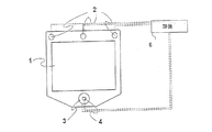
図1にはコンピュータのユーザが注視/凝視しているモニタ1上の点を決定する装置が示されている。決定はユーザの眼を追跡することによって、特に眼の凝視角度とモニタから眼までの距離を決定することによって行われる。装置はモニタ1、モニタ1の上縁部の直線に沿って装着された3つの同一の光源2、モニタの底縁部の中心に配置され、不要な光線をフィルタリングして除去し、かつフォトセンサの感応面上へピクチャの焦点を合わせるの双方のためにフォトセンサの前に配置されている適切な光学系(図示せず)を備えたフォトセンサ4と、フォトセンサの光軸と同軸に配置されている、すなわちフォトセンサの感応面の全ての側の周りに配置されている光源3とを含んでいる。感応面は図示のように、長方形の形状を有している。同軸の光源3は、図3a、3bを参照すると、2つの群、すなわち第1の内側の群と第2の外側の群内に配置されている複数の発光素子3'、3”を含んでいる。内側の群内では発光素子3'は感応面の縁部又は側部の近傍に配置されている。長方形の感応性領域を含む実施形態では、3つの素子が長方形のそれぞれの長辺に沿って配置され、2つの素子がその短辺に配置されている。外側の群内には、発光素子3”が感応領域の中心から見て内側の群内の素子の外側に、感応領域から大きい距離を隔てて配置されている。図示した実施形態では、外側の群内には内側の群内と同数の素子が示されており、外側の群内の各素子は長方形の感応領域の中心から見て、内側の群内の2つの素子の間に配置されている。
FIG. 1 shows an apparatus for determining a point on a
図1に示されている装置の実際の実施形態では、中央のダイオードの周囲に対称に配置された6つのダイオードを含む7つのNIRダイオード、HSDL4230を各々が含む3つの同一の光源2が備えられている。図3a、3bに基づいて設計された照明ユニット3内の発光素子3'、3”と同じ種類のダイオードが使用される。
In the actual embodiment of the device shown in FIG. 1, there are provided seven identical NIR diodes, six comprising six diodes arranged symmetrically around a central diode, three
これらの構成要素に加えて、必要な制御やこれに関連する評価と計算を行うために、6で示されている調整用の計算及び制御ユニットだけが備えられている。計算及び制御ユニットは光源のスイッチのオン・オフを制御する。さらに、これはフォトセンサ4によって取り込まれた画像の処理、特に境界線、すなわち異なるグレー・スケール強度又はカラーを有するピクチャ内のフィールド間の線の決定を行う。眼の像内で、特に瞳孔の境界を定める境界線が決定され、そこから瞳孔の中心が得られる。これは例えば瞳孔の境界を定めるものと決定された境界線に円又は楕円を適合させることによって行うことができる。計算及び制御ユニット6は後述するように、フォトセンサ4からのデータ出力を制御する、すなわち取り込まれた画像内の、フォトセンサから計算及び制御ユニットまで情報が送られる画素を決定することもできる。
In addition to these components, only the adjustment calculation and control unit indicated at 6 is provided to perform the necessary controls and the associated evaluations and calculations. The calculation and control unit controls the turning on and off of the light source. In addition, it performs the processing of the image captured by the
図3a、3bには、内側と外側の群の発光素子をスイッチオン、スイッチオフすることによって、フォトセンサ4の周囲に配置された光源3内の素子が2つの異なる方法で眼を照明することができる態様が示されている。図3に示されている、内側の群内の素子だけがスイッチオンされる1つの光線設定位置によって、フォトセンサにより検知される瞳孔の、容易に確認できるブライト・アイ効果が生じ、一方、図3bに示されている、外側の群内の素子だけがスイッチオンされる他の設定位置によって、容易に確認できるブライト・アイ効果を誘発することなく角膜からの反射が生ずる。
3a and 3b show that the elements in the
図1の装置が動作される際には、これは2つの光線設定位置を交代させる。設定位置(i)はユーザが見ている方向を決定するために設けられている。光線設定位置(ii)では、ユーザの眼からフォトセンサまでの距離が決定される。双方の光線設定位置で、フォトセンサの二次元座標系で見てユーザの眼(単数又は複数)が位置する場所に関する情報も得られる。 When the apparatus of FIG. 1 is operated, this alternates the two light set positions. The setting position (i) is provided to determine the direction in which the user is looking. At the light beam setting position (ii), the distance from the user's eyes to the photosensor is determined. Information on the location of the user's eye (s) as viewed in the two-dimensional coordinate system of the photosensor at both light setting positions is also obtained.
装置が光線設定位置(i)にある場合は、フォトセンサ4の視野と同軸に配置されている光源3の内側の素子3'は図3aに示された設定位置でスイッチオンされ、フォトセンサの視野内の全ての瞳孔について強いブライト・アイ効果を与える。この光線設定位置で、モニタ1の周囲に位置する3つの光源2すべてはスイッチオフされる。すなわち内側の群内の素子だけがスイッチオンされる。次にフォトセンサ4の視野内の瞳孔の画像はブライト・アイ効果により照明される瞳孔5が図示されている図4に示されるように見え(図4bと比較されたい)、角膜からの光源3の反射は点形の反射3'aのように見える。取り込まれた画像は計算ユニット6によって分析され、図4bに示すように境界線が決定される。ブライト・アイ効果について取り込まれたピクチャ内において瞳孔と虹彩に対応するイメージ・フィールド間には特に強いコントラストがあり(別の照明を利用して取り込まれた図5aのピクチャと比較されたい)、したがってこれらの2つのフィールド間の境界線を優れた精度で計算することができる。この精確に決定された境界線は瞳孔の境界を定め、そこから結果的にこれも優れた精度で瞳孔の中心を決定することができる。前述のように、中心を決定する際、境界線に楕円形を適合させることを利用でき、これは瞳孔がピクチャ内で部分的にしか見えない場合に特に重要である。さらに、ピクチャ内で、反射3'aの位置と特に反射の中心が決定される。最後に、反射3a’の中心からの瞳孔5の中心へのベクトルが計算される。
When the device is in the light set position (i), the
凝視方向、すなわちユーザが見ている方向を決定するため、上記の説明に基づいて決定されたベクトルが利用される。このベクトルの方向はカメラの光軸から捉えたユーザが見ている方向を示し、ベクトルの大きさはこれもカメラの光軸に対して捉えたユーザが見ている角度を示す。さらに、反射3'aの中心は二次元で見たユーザの眼の位置に関する情報をもたらす。 In order to determine the gaze direction, i.e. the direction the user is looking at, a vector determined based on the above description is used. The direction of the vector indicates the direction viewed by the user viewed from the optical axis of the camera, and the magnitude of the vector also indicates the angle viewed by the user viewed relative to the optical axis of the camera. Furthermore, the center of the reflection 3'a provides information about the position of the user's eye viewed in two dimensions.
システムが光線設定位置(ii)にある場合は、フォトセンサの視野と同軸である光源3内の外側の群内の素子3”は、明確に確認できるブライト・アイ効果を生じない、図3bに示されている光線設定位置にスイッチされる。同時に、モニタの上縁部に位置する3つの光源2はこの光線設定位置にスイッチオンされる。図5aはこの設定位置で、眼の異なる位置に対応するイメージ・フィールド間のコントラストが比較的低い状態でフォトセンサ4上に眼を結像させる態様を示している。さらに図5bに示されているように、このピクチャが境界線を得るために分析され、眼の異なる部分に対応するフィールドの決定された境界線の精度は図4bに基づいて瞳孔の境界を定める境界線よりも低いことがある。しかし、図5bに示されたピクチャでは、異なる反射は極めて明瞭に見える。3'b(図5bの分析されたピクチャを参照)に、図3bに見られる場合に基づいてスイッチオンされた光源3の角膜からの反射が示されており、2'にはモニタの上縁部に位置する光源2の角膜からの反射が示されている。異なる反射の位置とその距離はピクチャ内で決定され、その場合の決定は良好な精度で行うことができる。フォトセンサ4から眼までの距離を決定するために、4つの反射のパターン、すなわち主として異なる反射の相互の位置が評価される。特に、2'、3'bでの4つの反射によって形成されるパターンのサイズはフォトセンサから眼までの距離によって左右される。眼がフォトセンサから遠い距離に位置するほど、パターンの寸法は小さくなる。このように、モニタ1がユーザの眼の位置から離れている距離の尺度が得られる。この場合はさらに、3'bでの同軸の光源3の反射からユーザの眼が位置する二次元の場所に関する情報が得られる。
When the system is in the light set position (ii), the
このように、図1のシステムは動作時に光線設定位置(i)と光線設定位置(ii)の間で交代する。ユーザが見ているモニタ上の位置を示すことができるにはこれらの2つの光線設定位置からの情報が必要である。光線設定位置(i)では、ユーザの凝視方向が検知され、光線設定位置(ii)では、ユーザの位置が検知される。コンピュータのユーザにとって、眼の動きは通常は頭の動きよりもずっと迅速である。このことは、ユーザが見ているコンピュータのモニタ上の点を決定する際の優れた精度を得るためには、フォトセンサ4から奥行き方向でのユーザの位置に関する情報よりも、ユーザの凝視角度に関する最新の更新情報を有することのほうが重要であることを意味している。経験によれば、光線設定位置(i)で取り込まれた4つのピクチャが光線設定位置(ii)での各ピクチャに対して分析された場合に、優れた精度を有するシステムが得られることが示されている。凝視点を決定するためには、光線設定位置(i)で撮られた最後のピクチャからの情報と光線設定位置(ii)で取り込まれた最後のピクチャからの情報が常に利用される。
Thus, the system of FIG. 1 alternates between the light set position (i) and the light set position (ii) during operation. Information from these two ray setting positions is needed to be able to indicate the position on the monitor that the user is looking at. The user's gaze direction is detected at the light beam setting position (i), and the user's position is detected at the light beam setting position (ii). For computer users, eye movements are usually much faster than head movements. In order to obtain excellent accuracy in determining a point on the computer monitor that the user is looking at, this relates to the user's gaze angle rather than information about the user's position in the depth direction from the
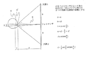
図2には2つの光源の反射像間の距離が、反射面から光源及び同じ平面に位置するものと想定されている検知器までの距離に左右される態様を概略的に示している。反射面と光源を通る平面との距離は像間の距離の平方根とほぼ反比例する。このような関係、又は図2に示されているような幾分より正確な関係は装置の個々の校正で得られる絶対値と共に、例えばユーザの頭が動くときに各ユーザがモニタ上のカーソルを制御するための充分に正確な距離の決定が与えられるために利用可能である。 FIG. 2 schematically shows an aspect in which the distance between the reflected images of the two light sources depends on the distance from the reflecting surface to the light source and the detector assumed to be located on the same plane. The distance between the reflecting surface and the plane passing through the light source is almost inversely proportional to the square root of the distance between images. Such a relationship, or a somewhat more accurate relationship as shown in FIG. 2, along with the absolute values obtained from individual calibrations of the device, for example, each user moves the cursor on the monitor as the user's head moves. It can be used to provide a sufficiently accurate distance determination to control.
上記の装置で使用されるフォトセンサは高解像度形のものである。このようにして、ユーザは精度の劣化を招くことなく彼女/彼の頭をより大きく動かすことが許容される。計算ユニットへの負荷を軽減し、システムのサンプリング速度を高めるために、その際にフォトセンサからのデータは必要以上には使用されない。計算ユニットは、各々の新たなピクチャが撮られ、又は各々の新たなピクチャ内で使用される前に露光されるべきフォトセンサの感応面の部分を選択するために眼が以前のピクチャ内で検出した部分に関する情報を利用し、これに従ってフォトセンサを制御する。ユーザの眼が先行ピクチャで検出された場合は、フォトセンサの感応面の画素の小部分だけしか利用されない。眼が認められなかった場合に限り、フォトセンサの感応面の全ての画素からのデータが利用され、又はいずれにせよ、例えば全ピクチャ領域についてデータのダウン・サンプリングによって得られたピクチャ全体を表すデータが使用される。このようにして、眼と奥行き方向での眼の距離を検知するのは比較的遅いが、眼が検出された後は眼、及び特に凝視方向を高速度で追跡可能であるシステムが得られる。 The photosensor used in the above apparatus is of a high resolution type. In this way, the user is allowed to move her / his head more greatly without incurring a loss of accuracy. In order to reduce the load on the calculation unit and increase the sampling rate of the system, the data from the photosensor is not used more than necessary. The computational unit detects the eye in the previous picture to select the part of the photosensor sensitive surface that should be exposed before each new picture is taken or used in each new picture Information on the selected part is used, and the photosensor is controlled accordingly. When the user's eyes are detected in the preceding picture, only a small part of the pixels on the sensitive surface of the photosensor is used. Data from all pixels on the sensitive surface of the photosensor is used only if no eyes are recognized, or in any case, data representing the entire picture, for example obtained by down-sampling the data for the entire picture area Is used. In this way, it is relatively slow to detect the distance between the eye and the eye in the depth direction, but after the eye is detected, a system is obtained that can track the eye, and particularly the gaze direction, at high speed.
眼は、眼の位置及び凝視方向と共に図4a又は5aに示されているように取り込まれたピクチャが現れる態様を制御するユニークな物理特性を有している。これらのピクチャから得ることができるデータから人が見ている位置を決定できるようにするため、システムは必要ならばモニタの前に座っている人に対して個々に校正可能である。加えて、システムは眼がどの眼であるのか、すなわち図4b及び5bに基づいて計算された境界線がユーザの左眼と右眼のどちらに関連しているかを知る必要がある。 The eye has unique physical properties that control the manner in which the captured picture appears as shown in FIG. 4a or 5a along with the eye position and gaze direction. In order to be able to determine the position a person is looking at from the data available from these pictures, the system can be individually calibrated to the person sitting in front of the monitor if necessary. In addition, the system needs to know which eye the eye is, ie whether the boundary calculated based on FIGS. 4b and 5b relates to the user's left eye or right eye.
フォトセンサ4にユーザの両眼が見える場合は、どれが左眼でどれが右眼であるかを示すことは容易であるが、片眼だけしか検出されない場合は、それがどちらの眼であるかを決定するためには別の方法が必要である。ここでこのような方法を説明し、その様々なステップも図6の流れ図で示す。影響を及ぼす第1の要因はユーザの眼が動く速度である。眼が動くことができる速度には上限がある。その結果、以前のピクチャの所定位置に判明している眼がある場合は、この眼は以前のピクチャが取り込まれた後、限定された距離しか動くことができない。したがって、前から判明している眼と新たに検出された眼との距離が長すぎる場合は、今検出された眼は以前に検知された眼とは異なる眼である。以前から判明している眼がその時点で判明している唯一の眼である場合でも、他の眼がそこに位置している領域があった筈である。このようにして、判明していない眼が新たな眼が検出された位置に移動し得たのか否かを決定するためにユーザの眼の間の距離を利用できる。この距離がユーザの片眼についてだけにしては充分に短い場合は、検出された眼はこの眼と同一のものである筈である。
When the user's eyes are visible on the
前記の判断基準がどの眼が検出されたかに関する情報を与えない場合は、検討に値する別の要因が存在する。この要因は眼がフォトセンサの縁部にどの程度近接した位置にあるかということである。眼の位置が、他の眼がセンサの視野の外側に位置するほどフォトセンサの縁部に近接している場合で、この眼が検出された眼の外側にあった場合は、これがその通りであるか、又は他の眼がフォトセンサの凝視角内に位置しているか、おそらくはユーザが眼を閉じているために隠れているかのいずれかである。この場合はシステムは、検出された眼が、他の眼がフォトセンサの視野の外側にあることを示唆する眼であるものと推測することが許容される。どの眼が検出されたのかをシステムが推測した後、システムから送られるデータにより低い機密レベルが設定され、これらのデータが安全ではないことが示される。 If the above criteria do not give information about which eye has been detected, there are other factors worthy of consideration. This factor is how close the eye is to the edge of the photosensor. If the eye is so close to the edge of the photosensor that the other eye is outside the field of view of the sensor, and this eye is outside the detected eye, this is true Either the other eye is located within the gaze angle of the photosensor, or is probably hidden because the user has closed the eye. In this case, the system is allowed to infer that the detected eye is an eye that suggests that the other eye is outside the field of view of the photosensor. After the system has guessed which eye has been detected, the data sent from the system is set to a lower security level, indicating that these data are not secure.
図7には人の眼及び凝視方向を決定し、追跡する際に実行される様々なステップの流れ図が示されている。最初のステップ71で、光線設定位置(i)、すなわち素子3'だけがスイッチオンされている位置での照明でピクチャが取り込まれる。ピクチャ内で瞳孔、すなわちそれらの境界線と光源の反射とが決定される。次のブロック73で、どれがどの眼であるかを決定するために図6に基づく手順が実行される。次にステップ75で、ピクチャ内で両眼が検出されたか否かが決定される。検出された場合はブロック77が実行され、そこで設定位置(ii)での照明で、すなわち素子3”がスイッチオンされ、ダイオード2が起動される位置でピクチャが取り込まれる。このピクチャでは、検出された眼の周囲領域に関する情報だけがユニット6に送られる。ピクチャ内の眼の反射及びひいては像が決定される。その後、ブロック79でどれがどの眼であるかを決定するために再び図6に基づく手順が実行される。次のステップ81で、ピクチャ内に両眼が検出されたか否かが決定される。検出された場合は、ブロック83で眼が観察している点の計算がユニット6で行われる。次にブロック85が実行され、そこで光線設定位置(i)、すなわち素子3'だけがスイッチオンされている照明によって再びピクチャが取り込まれる。取り込まれた画像については、検出された眼の周囲領域の情報だけがユニット6に送られる。限定されたピクチャ情報から、ステップ71と同様に瞳孔及び光源の反射が決定される。次にブロック87で、どれがどの眼であるかを決定するために図6に基づく手順が再び実行される。次のステップ89で、両眼がピクチャ内で検出されたか否かが決定される。検出されている場合は、ブロック91で眼によって観察され、又は凝視された点の計算がブロック83と同様の方法で行われる。その後ブロック93で、取り込まれた最後の4つのピクチャが光線設定位置(ii)での照明で取り込まれたのか否かの決定が行われる。そうではない場合は、ブロック85が再び実行され、そうである場合はブロック77が実行される。ブロック75、81、及び89のいずれかで両眼が検出されないことが決定されると、ブロック71が再び実行される。
FIG. 7 shows a flowchart of the various steps performed in determining and tracking the human eye and gaze direction. In a
これまで本明細書に本発明の特定の実施形態を記載してきたが、当業者には多くの付加的な利点、修正、及び変更が容易に可能であることが理解されよう。したがって、本発明は広義の態様で本明細書に示し、記載してきた特定の細部、代表的なデバイス、及び例示に限定されるものではない。したがって、添付の特許請求の範囲によって定義された基本的な発明的概念、及びそれと同類の趣旨又は範囲を逸脱することなく、様々な修正を行ってもよい。したがって、添付の特許請求の範囲は本発明のこれらの真の趣旨及び範囲のこのような修正、及び変更全てを包括することを企図するものであると理解されたい。 While specific embodiments of the present invention have been described herein, those skilled in the art will recognize that many additional advantages, modifications, and changes are readily possible. Accordingly, the present invention is not limited to the specific details, representative devices, and illustrations shown and described herein in a broad sense. Accordingly, various modifications may be made without departing from the basic inventive concept defined by the appended claims and the similar spirit or scope. Therefore, it is to be understood that the appended claims are intended to cover all such modifications and changes in these true spirits and scope of the invention.
Claims (17)
ユーザの頭部からの光線を受光し、そのピクチャを反復的に取り込む検知器と、
眼の位置及び/又は凝視方向を決定するために前記検知器に接続された評価ユニットと、を備える眼検知装置であって、
前記評価ユニットは、
前記検知器によって取り込まれたピクチャ内の、単数又は複数の目の像が位置している領域を決定し、
前記領域の決定後、前記検知器によって取り込まれた像の前記決定された領域に対応する連続的な、又は後続のピクチャに関する情報だけを前記評価ユニットに送るように前記検知器を制御し、
眼の検知を行うために前記評価ユニットに送られた情報を用いて前記検知器に対する奥行き方向と横方向における眼の位置を決定し、
前記検知器は、前記決定された領域に対応する前記検知器の表面部分からの情報だけを、ひいては次に前記評価ユニットに送られるデータを読み出し、
前記評価ユニットは、さらに、
前記検知器によって取り込まれた現在のピクチャ内に前記ピクチャがユーザの両眼の像を含んでいるか否かを決定し、
前記評価ユニットが前記現在のピクチャ内に片眼の像だけが存在することを決定した場合は、前記眼の像が前記現在のピクチャ内で前記以前に取り込まれたピクチャ内の前記眼の前記像の位置に充分に近接した位置を有しているならば、この眼が以前に取り込まれたピクチャ内の像を有するものと同じ眼であることを決定するように構成されていることを特徴とする眼検知装置。One or more light sources that emit light in the direction of the user's head;
A detector that receives light from the user's head and repeatedly captures the picture;
An eye detection device comprising: an evaluation unit connected to the detector for determining an eye position and / or gaze direction;
The evaluation unit is
Determining the region in the picture captured by the detector where the image or images of the eye are located;
After determining the region, controlling the detector to send only information about successive or subsequent pictures corresponding to the determined region of the image captured by the detector to the evaluation unit;
Determining the position of the eye in the depth direction and the lateral direction relative to the detector using information sent to the evaluation unit to perform eye detection;
The detector, only the information from the surface portion of the detector that corresponds to the determined area, and read out the data to be sent and thus then to the evaluation unit,
The evaluation unit further comprises:
Determining whether the picture contains a binocular image of the user within the current picture captured by the detector;
If the evaluation unit determines that there is only one eye image in the current picture, the eye image is the image of the eye in the previously captured picture in the current picture. If it has a position sufficiently close to the position of the eye, this eye is configured to determine that it is the same eye that has the image in the previously captured picture. Eye detection device.
前記評価ユニットは前記検知器に対する前記眼の前記位置を決定するために、取り込まれた像内の前記光源の前記反射像の位置を利用するように構成されていることを特徴とする請求項1から3のいずれか一項に記載の眼検知装置。At least two light sources disposed at a distance from each other so as to emit at least two light beams reflected from the cornea of the user's eye;
2. The evaluation unit is configured to utilize the position of the reflected image of the light source in a captured image to determine the position of the eye relative to the detector. 4. The eye detection device according to any one of items 1 to 3 .
ユーザの頭部からの光線を受光し、そのピクチャを反復的に取り込む検知器と、
眼の位置及び/又は凝視方向を決定するために前記検知器に接続された評価ユニットと、を備える眼検知装置であって、
前記評価ユニットは、
前記検知器によって取り込まれた現在のピクチャ内で、前記ピクチャがユーザの両眼の像を含んでいるか否かを決定し、
前記評価ユニットが前記現在のピクチャ内に片眼の像だけが存在することを決定した場合は、前記眼の像が前記現在のピクチャ内で前記以前に取り込まれた像の前記眼の像の位置に充分に近接した位置を有しているならば、この眼がその像が以前に取り込まれたピクチャ内に存在するものと同じ眼であることを決定するように構成されていることを特徴とする眼検知装置。One or more light sources for emitting light in the direction of the user's head;
A detector that receives light from the user's head and repeatedly captures the picture;
An eye detection device comprising: an evaluation unit connected to the detector for determining an eye position and / or gaze direction;
The evaluation unit is
Determining whether in the current picture captured by the detector, the picture contains a binocular image of the user;
If the evaluation unit determines that there is only one eye image in the current picture, the position of the eye image of the previously captured image in the current picture is the eye image. The eye is configured to determine that the image is the same eye that exists in the previously captured picture. Eye detection device.
ユーザの頭部からの光線を受光し、そのピクチャを反復的に取り込む検知器と、
前記検知器に接続された評価ユニットと、を備える眼検知装置であって、
前記少なくとも2つの光源はユーザの眼から反射される少なくとも2つの光ビームを発するために互いに距離を隔てて配置され、かつ、
前記評価ユニットは前記検知器に対する前記眼の前記位置を決定するために、取り込まれた像内の前記光源の前記反射像の位置を利用し、
前記光源は2つの群に区分され、第1群の光源はこの群だけからの照明で取り込まれるピクチャから、前記眼の前記凝視方向を決定するのに適した光線を発するように構成され、第2群の光源はこの群だけからの照明で取り込まれたピクチャから、前記検知器から前記眼までの距離を決定するのに適した光線を発するように構成され、前記制御ユニットは各ピクチャを取り込む際にこれらの群の一方又は双方を起動するように構成されていることを特徴とする眼検知装置。At least two light sources for emitting light in the direction of the user's head;
A detector that receives light from the user's head and repeatedly captures the picture;
An evaluation unit connected to the detector, and an eye detection device comprising:
The at least two light sources are spaced apart from each other to emit at least two light beams reflected from the user's eye; and
The evaluation unit utilizes the position of the reflected image of the light source in the captured image to determine the position of the eye relative to the detector;
The light sources are divided into two groups, and the first group of light sources is configured to emit light suitable for determining the gaze direction of the eye from pictures captured by illumination from only this group, Two groups of light sources are configured to emit light suitable for determining the distance from the detector to the eye from pictures captured with illumination from only this group, and the control unit captures each picture An eye detection device configured to activate one or both of these groups at the time.
Applications Claiming Priority (3)
| Application Number | Priority Date | Filing Date | Title |
|---|---|---|---|
| SE0203457A SE524003C2 (en) | 2002-11-21 | 2002-11-21 | Procedure and facility for detecting and following an eye and its angle of view |
| SE0203457-7 | 2002-11-21 | ||
| PCT/SE2003/001813 WO2004045399A1 (en) | 2002-11-21 | 2003-11-21 | Method and installation for detecting and following an eye and the gaze direction thereof |
Related Child Applications (1)
| Application Number | Title | Priority Date | Filing Date |
|---|---|---|---|
| JP2011046089A Division JP5297486B2 (en) | 2002-11-21 | 2011-03-03 | Device for detecting and tracking the eye and its gaze direction |
Publications (2)
| Publication Number | Publication Date |
|---|---|
| JP2006507054A JP2006507054A (en) | 2006-03-02 |
| JP4783018B2 true JP4783018B2 (en) | 2011-09-28 |
Family
ID=20289646
Family Applications (2)
| Application Number | Title | Priority Date | Filing Date |
|---|---|---|---|
| JP2004553361A Expired - Fee Related JP4783018B2 (en) | 2002-11-21 | 2003-11-21 | Method and apparatus for detecting and tracking the eye and its gaze direction |
| JP2011046089A Expired - Fee Related JP5297486B2 (en) | 2002-11-21 | 2011-03-03 | Device for detecting and tracking the eye and its gaze direction |
Family Applications After (1)
| Application Number | Title | Priority Date | Filing Date |
|---|---|---|---|
| JP2011046089A Expired - Fee Related JP5297486B2 (en) | 2002-11-21 | 2011-03-03 | Device for detecting and tracking the eye and its gaze direction |
Country Status (12)
| Country | Link |
|---|---|
| US (1) | US7572008B2 (en) |
| EP (1) | EP1562469B1 (en) |
| JP (2) | JP4783018B2 (en) |
| CN (1) | CN100421614C (en) |
| AT (1) | ATE432038T1 (en) |
| AU (1) | AU2003284816A1 (en) |
| DE (1) | DE60327798D1 (en) |
| DK (1) | DK1562469T3 (en) |
| ES (1) | ES2327633T3 (en) |
| PT (1) | PT1562469E (en) |
| SE (1) | SE524003C2 (en) |
| WO (1) | WO2004045399A1 (en) |
Cited By (1)
| Publication number | Priority date | Publication date | Assignee | Title |
|---|---|---|---|---|
| WO2013141098A1 (en) | 2012-03-21 | 2013-09-26 | 国立大学法人浜松医科大学 | Asperger's diagnosis assistance method and system, and asperger's diagnosis assistance device |
Families Citing this family (206)
| Publication number | Priority date | Publication date | Assignee | Title |
|---|---|---|---|---|
| US7963652B2 (en) | 2003-11-14 | 2011-06-21 | Queen's University At Kingston | Method and apparatus for calibration-free eye tracking |
| WO2005046465A1 (en) * | 2003-11-14 | 2005-05-26 | Queen's University At Kingston | Method and apparatus for calibration-free eye tracking |
| JP4500992B2 (en) * | 2004-01-14 | 2010-07-14 | 国立大学法人静岡大学 | 3D viewpoint measuring device |
| US10039445B1 (en) | 2004-04-01 | 2018-08-07 | Google Llc | Biosensors, communicators, and controllers monitoring eye movement and methods for using them |
| CA2561287C (en) * | 2004-04-01 | 2017-07-11 | William C. Torch | Biosensors, communicators, and controllers monitoring eye movement and methods for using them |
| US7322696B2 (en) * | 2004-04-19 | 2008-01-29 | Shamir Optical Industry | Customized lens, and system and method of producing thereof |
| ES2568506T3 (en) | 2004-06-18 | 2016-04-29 | Tobii Ab | Eye control of computer equipment |
| CN1293446C (en) * | 2005-06-02 | 2007-01-03 | 北京中星微电子有限公司 | Non-contact type visual control operation system and method |
| CN101272727B (en) | 2005-09-27 | 2011-09-07 | 潘尼公司 | A device for controlling an external unit |
| EP1933694B1 (en) | 2005-10-10 | 2020-07-22 | Tobii AB | Eye tracker having an extended span of operating distances |
| ES2605367T3 (en) | 2006-01-26 | 2017-03-14 | Nokia Technologies Oy | Eye tracking device |
| WO2007101690A1 (en) * | 2006-03-09 | 2007-09-13 | Tobii Technology Ab | Eye determination apparatus |
| EP2033175A4 (en) * | 2006-05-04 | 2011-07-06 | Nat Ict Australia Ltd | An electronic media system |
| US8197539B2 (en) | 2006-05-05 | 2012-06-12 | University Of Southern California | Intraocular camera for retinal prostheses |
| US20080147488A1 (en) * | 2006-10-20 | 2008-06-19 | Tunick James A | System and method for monitoring viewer attention with respect to a display and determining associated charges |
| KR100850357B1 (en) * | 2006-12-06 | 2008-08-04 | 한국전자통신연구원 | System and method for tracking gaze |
| ES2316272B1 (en) * | 2007-02-16 | 2009-11-30 | Iriscom Sistemas, S.L . | OCULAR FOLLOW-UP SYSTEM FOR THE GOVERNMENT OF A COMPUTER. |
| GB0709405D0 (en) | 2007-05-16 | 2007-06-27 | Univ Edinburgh | Testing vision |
| WO2008141460A1 (en) | 2007-05-23 | 2008-11-27 | The University Of British Columbia | Methods and apparatus for estimating point-of-gaze in three dimensions |
| DE102008006090A1 (en) | 2008-01-25 | 2009-07-30 | Claudius Zelenka | Eye's position detecting method for medical and military field, involves detecting and suppressing disturbing reflex from environment by evaluation of polarization of images taken by camera, and linearly polarizing light source |
| PL2242419T3 (en) * | 2008-02-14 | 2016-05-31 | Nokia Technologies Oy | Device and method for determining gaze direction |
| JP5163982B2 (en) * | 2008-06-16 | 2013-03-13 | 国立大学法人神戸大学 | Gaze measurement device, gaze measurement program, gaze measurement method, and display for gaze measurement device |
| TWI432172B (en) * | 2008-10-27 | 2014-04-01 | Utechzone Co Ltd | Pupil location method, pupil positioning system and storage media |
| US20100118199A1 (en) * | 2008-11-10 | 2010-05-13 | Kabushiki Kaisha Toshiba | Video/Audio Processor and Video/Audio Processing Method |
| CN102292017B (en) * | 2009-01-26 | 2015-08-05 | 托比股份公司 | The detection to fixation point of being assisted by optical reference signal |
| CN101807110B (en) * | 2009-02-17 | 2012-07-04 | 由田新技股份有限公司 | Pupil positioning method and system |
| EP2238889B1 (en) | 2009-04-01 | 2011-10-12 | Tobii Technology AB | Adaptive camera and illuminator eyetracker |
| WO2010118292A1 (en) | 2009-04-09 | 2010-10-14 | Dynavox Systems, Llc | Calibration free, motion tolerant eye-gaze direction detector with contextually aware computer interaction and communication methods |
| US20100321482A1 (en) * | 2009-06-17 | 2010-12-23 | Lc Technologies Inc. | Eye/head controls for camera pointing |
| US9507418B2 (en) | 2010-01-21 | 2016-11-29 | Tobii Ab | Eye tracker based contextual action |
| TWI497247B (en) * | 2010-01-28 | 2015-08-21 | Chi Mei Comm Systems Inc | Data processing device and method for regulating the lighting power of a display |
| US20110205148A1 (en) * | 2010-02-24 | 2011-08-25 | Corriveau Philip J | Facial Tracking Electronic Reader |
| JP5529660B2 (en) * | 2010-07-20 | 2014-06-25 | パナソニック株式会社 | Pupil detection device and pupil detection method |
| US9760123B2 (en) | 2010-08-06 | 2017-09-12 | Dynavox Systems Llc | Speech generation device with a projected display and optical inputs |
| KR20120057033A (en) * | 2010-11-26 | 2012-06-05 | 한국전자통신연구원 | Gaze tracking system and method for controlling internet protocol tv at a distance |
| US9185352B1 (en) | 2010-12-22 | 2015-11-10 | Thomas Jacques | Mobile eye tracking system |
| US20120244935A1 (en) * | 2011-03-24 | 2012-09-27 | International Business Machines Corporation | Synchronizing game character display with game player viewing detection |
| US8885877B2 (en) | 2011-05-20 | 2014-11-11 | Eyefluence, Inc. | Systems and methods for identifying gaze tracking scene reference locations |
| US8911087B2 (en) | 2011-05-20 | 2014-12-16 | Eyefluence, Inc. | Systems and methods for measuring reactions of head, eyes, eyelids and pupils |
| US8885882B1 (en) | 2011-07-14 | 2014-11-11 | The Research Foundation For The State University Of New York | Real time eye tracking for human computer interaction |
| US20130033524A1 (en) * | 2011-08-02 | 2013-02-07 | Chin-Han Wang | Method for performing display control in response to eye activities of a user, and associated apparatus |
| JP5912351B2 (en) | 2011-09-05 | 2016-04-27 | 国立大学法人浜松医科大学 | Autism diagnosis support system and autism diagnosis support apparatus |
| CN103782255B (en) * | 2011-09-09 | 2016-09-28 | 泰利斯航空电子学公司 | The eye of vehicle audio entertainment system moves Tracing Control |
| WO2013051307A1 (en) * | 2011-10-06 | 2013-04-11 | 本田技研工業株式会社 | Warning device |
| US8976110B2 (en) | 2011-10-27 | 2015-03-10 | Tobii Technology Ab | Power management in an eye-tracking system |
| DK2587341T3 (en) | 2011-10-27 | 2017-04-03 | Tobii Ab | Power management in an eye tracking system |
| EP2587342A1 (en) | 2011-10-28 | 2013-05-01 | Tobii Technology AB | Method and system for user initiated query searches based on gaze data |
| US9071740B1 (en) | 2011-10-28 | 2015-06-30 | Google Inc. | Modular camera system |
| US8929589B2 (en) | 2011-11-07 | 2015-01-06 | Eyefluence, Inc. | Systems and methods for high-resolution gaze tracking |
| US8860660B2 (en) | 2011-12-29 | 2014-10-14 | Grinbath, Llc | System and method of determining pupil center position |
| US9910490B2 (en) | 2011-12-29 | 2018-03-06 | Eyeguide, Inc. | System and method of cursor position control based on the vestibulo-ocular reflex |
| CN102436306A (en) * | 2011-12-30 | 2012-05-02 | 四川虹欧显示器件有限公司 | Method and device for controlling 3D display system |
| US10540008B2 (en) | 2012-01-04 | 2020-01-21 | Tobii Ab | System for gaze interaction |
| US10394320B2 (en) | 2012-01-04 | 2019-08-27 | Tobii Ab | System for gaze interaction |
| US10488919B2 (en) | 2012-01-04 | 2019-11-26 | Tobii Ab | System for gaze interaction |
| US10013053B2 (en) | 2012-01-04 | 2018-07-03 | Tobii Ab | System for gaze interaction |
| US10025381B2 (en) | 2012-01-04 | 2018-07-17 | Tobii Ab | System for gaze interaction |
| US9197686B1 (en) | 2012-01-06 | 2015-11-24 | Google Inc. | Backfill of video stream |
| DE102012003283A1 (en) | 2012-02-20 | 2013-08-22 | 4tiitoo AG | Method for view based control of computer system, involves generating control signal for output device of computer system and/or computing device in response to result of evaluation of output data of device for eye tracking control |
| EP2696259B1 (en) | 2012-08-09 | 2021-10-13 | Tobii AB | Fast wake-up in a gaze tracking system |
| US9575960B1 (en) * | 2012-09-17 | 2017-02-21 | Amazon Technologies, Inc. | Auditory enhancement using word analysis |
| JP6056323B2 (en) * | 2012-09-24 | 2017-01-11 | 富士通株式会社 | Gaze detection device, computer program for gaze detection |
| US20140085198A1 (en) | 2012-09-26 | 2014-03-27 | Grinbath, Llc | Correlating Pupil Position to Gaze Location Within a Scene |
| EP2712541B1 (en) | 2012-09-27 | 2015-12-30 | SensoMotoric Instruments Gesellschaft für innovative Sensorik mbH | Tiled image based scanning for head and/or eye position for eye tracking |
| CN103777861A (en) * | 2012-10-23 | 2014-05-07 | 韩国电子通信研究院 | Terminal and method for controlling touch operation in the terminal |
| US20140139556A1 (en) * | 2012-11-22 | 2014-05-22 | Shanghai Powermo Information Tech. Co. Ltd. | Apparatus and method for displaying software keyboards thereof |
| US9612656B2 (en) | 2012-11-27 | 2017-04-04 | Facebook, Inc. | Systems and methods of eye tracking control on mobile device |
| KR101417433B1 (en) * | 2012-11-27 | 2014-07-08 | 현대자동차주식회사 | User identification apparatus using movement of pupil and method thereof |
| US10528135B2 (en) | 2013-01-14 | 2020-01-07 | Ctrl-Labs Corporation | Wearable muscle interface systems, devices and methods that interact with content displayed on an electronic display |
| US9921648B2 (en) * | 2013-02-22 | 2018-03-20 | University Of Seoul Industry Cooperation Foundation | Apparatuses, methods and recording medium for control portable communication terminal and its smart watch |
| WO2014134623A1 (en) | 2013-03-01 | 2014-09-04 | Tobii Technology Ab | Delay warp gaze interaction |
| US9864498B2 (en) | 2013-03-13 | 2018-01-09 | Tobii Ab | Automatic scrolling based on gaze detection |
| US20140247208A1 (en) | 2013-03-01 | 2014-09-04 | Tobii Technology Ab | Invoking and waking a computing device from stand-by mode based on gaze detection |
| US9898081B2 (en) | 2013-03-04 | 2018-02-20 | Tobii Ab | Gaze and saccade based graphical manipulation |
| US10082870B2 (en) | 2013-03-04 | 2018-09-25 | Tobii Ab | Gaze and saccade based graphical manipulation |
| US11714487B2 (en) | 2013-03-04 | 2023-08-01 | Tobii Ab | Gaze and smooth pursuit based continuous foveal adjustment |
| US10895908B2 (en) | 2013-03-04 | 2021-01-19 | Tobii Ab | Targeting saccade landing prediction using visual history |
| US9665171B1 (en) | 2013-03-04 | 2017-05-30 | Tobii Ab | Gaze and saccade based graphical manipulation |
| GB2511868B (en) * | 2013-03-15 | 2020-07-15 | Tobii Ab | Eye/gaze tracker and method of tracking the position of an eye and/or a gaze point of a subject |
| US10262462B2 (en) | 2014-04-18 | 2019-04-16 | Magic Leap, Inc. | Systems and methods for augmented and virtual reality |
| US10042422B2 (en) | 2013-11-12 | 2018-08-07 | Thalmic Labs Inc. | Systems, articles, and methods for capacitive electromyography sensors |
| US11921471B2 (en) | 2013-08-16 | 2024-03-05 | Meta Platforms Technologies, Llc | Systems, articles, and methods for wearable devices having secondary power sources in links of a band for providing secondary power in addition to a primary power source |
| US20150124566A1 (en) | 2013-10-04 | 2015-05-07 | Thalmic Labs Inc. | Systems, articles and methods for wearable electronic devices employing contact sensors |
| US9143880B2 (en) | 2013-08-23 | 2015-09-22 | Tobii Ab | Systems and methods for providing audio to a user based on gaze input |
| ES2633016T3 (en) | 2013-08-23 | 2017-09-18 | Tobii Ab | Systems and methods to provide audio to a user according to a look input |
| US10686972B2 (en) | 2013-09-03 | 2020-06-16 | Tobii Ab | Gaze assisted field of view control |
| US10310597B2 (en) | 2013-09-03 | 2019-06-04 | Tobii Ab | Portable eye tracking device |
| US9665172B2 (en) | 2013-09-03 | 2017-05-30 | Tobii Ab | Portable eye tracking device |
| US9652034B2 (en) * | 2013-09-11 | 2017-05-16 | Shenzhen Huiding Technology Co., Ltd. | User interface based on optical sensing and tracking of user's eye movement and position |
| CN105723697B8 (en) | 2013-09-16 | 2020-10-13 | 英特尔公司 | Method, apparatus, device and storage medium for camera and light source synchronization |
| KR101503159B1 (en) * | 2013-10-15 | 2015-03-16 | (주)이스트소프트 | Method of controlling touch-screen detecting eyesight |
| JP6165979B2 (en) * | 2013-11-01 | 2017-07-19 | インテル コーポレイション | Gaze-assisted touch screen input |
| KR101470243B1 (en) * | 2013-11-15 | 2014-12-05 | 현대자동차주식회사 | Gaze detecting apparatus and gaze detecting method thereof |
| US10317995B2 (en) | 2013-11-18 | 2019-06-11 | Tobii Ab | Component determination and gaze provoked interaction |
| US10558262B2 (en) | 2013-11-18 | 2020-02-11 | Tobii Ab | Component determination and gaze provoked interaction |
| WO2015081113A1 (en) | 2013-11-27 | 2015-06-04 | Cezar Morun | Systems, articles, and methods for electromyography sensors |
| US9580081B2 (en) | 2014-01-24 | 2017-02-28 | Tobii Ab | Gaze driven interaction for a vehicle |
| DE102015202846B4 (en) | 2014-02-19 | 2020-06-25 | Magna Electronics, Inc. | Vehicle vision system with display |
| US10409366B2 (en) | 2014-04-28 | 2019-09-10 | Adobe Inc. | Method and apparatus for controlling display of digital content using eye movement |
| US9880632B2 (en) | 2014-06-19 | 2018-01-30 | Thalmic Labs Inc. | Systems, devices, and methods for gesture identification |
| US9874744B2 (en) | 2014-06-25 | 2018-01-23 | Thalmic Labs Inc. | Systems, devices, and methods for wearable heads-up displays |
| US9411417B2 (en) | 2014-07-07 | 2016-08-09 | Logitech Europe S.A. | Eye gaze tracking system and method |
| US9678567B2 (en) | 2014-07-16 | 2017-06-13 | Avaya Inc. | Indication of eye tracking information during real-time communications |
| GB2528446B (en) | 2014-07-21 | 2021-08-04 | Tobii Tech Ab | Method and apparatus for detecting and following an eye and/or the gaze direction thereof |
| US20170231058A1 (en) * | 2014-08-04 | 2017-08-10 | Innosys, Inc. | Lighting Systems |
| US9952883B2 (en) | 2014-08-05 | 2018-04-24 | Tobii Ab | Dynamic determination of hardware |
| US10288910B2 (en) | 2014-11-14 | 2019-05-14 | ESSILOR INTERNATIONAL Charenton-le-Pont | Devices and methods for determining the position of a characterizing point of an eye and for tracking the direction of the gaze of a wearer of spectacles |
| US9405120B2 (en) | 2014-11-19 | 2016-08-02 | Magna Electronics Solutions Gmbh | Head-up display and vehicle using the same |
| EP3051386A1 (en) | 2015-01-30 | 2016-08-03 | 4tiitoo GmbH | Eye tracking system and method |
| US10242379B2 (en) | 2015-01-30 | 2019-03-26 | Adobe Inc. | Tracking visual gaze information for controlling content display |
| SG11201706545VA (en) | 2015-02-17 | 2017-09-28 | Thalmic Labs Inc | Systems, devices, and methods for eyebox expansion in wearable heads-up displays |
| US10621431B2 (en) * | 2015-03-27 | 2020-04-14 | Lenovo (Singapore) Pte. Ltd. | Camera that uses light from plural light sources disposed on a device |
| GB201507224D0 (en) * | 2015-04-28 | 2015-06-10 | Microsoft Technology Licensing Llc | Eye gaze correction |
| US10197805B2 (en) | 2015-05-04 | 2019-02-05 | North Inc. | Systems, devices, and methods for eyeboxes with heterogeneous exit pupils |
| US9544485B2 (en) | 2015-05-27 | 2017-01-10 | Google Inc. | Multi-mode LED illumination system |
| US10488661B2 (en) | 2015-05-28 | 2019-11-26 | North Inc. | Systems, devices, and methods that integrate eye tracking and scanning laser projection in wearable heads-up displays |
| US9554063B2 (en) | 2015-06-12 | 2017-01-24 | Google Inc. | Using infrared images of a monitored scene to identify windows |
| US9235899B1 (en) | 2015-06-12 | 2016-01-12 | Google Inc. | Simulating an infrared emitter array in a video monitoring camera to construct a lookup table for depth determination |
| US9386230B1 (en) | 2015-06-12 | 2016-07-05 | Google Inc. | Day and night detection based on one or more of illuminant detection, lux level detection, and tiling |
| US9886620B2 (en) * | 2015-06-12 | 2018-02-06 | Google Llc | Using a scene illuminating infrared emitter array in a video monitoring camera to estimate the position of the camera |
| US9454820B1 (en) | 2015-06-12 | 2016-09-27 | Google Inc. | Using a scene illuminating infrared emitter array in a video monitoring camera for depth determination |
| JP6582604B2 (en) * | 2015-06-23 | 2019-10-02 | 富士通株式会社 | Pupil detection program, pupil detection method, pupil detection device, and gaze detection system |
| US10016130B2 (en) | 2015-09-04 | 2018-07-10 | University Of Massachusetts | Eye tracker system and methods for detecting eye parameters |
| EP3345021A4 (en) | 2015-09-04 | 2019-05-08 | North Inc. | Systems, articles, and methods for integrating holographic optical elements with eyeglass lenses |
| US10061383B1 (en) | 2015-09-16 | 2018-08-28 | Mirametrix Inc. | Multi-feature gaze tracking system and method |
| CA3007196A1 (en) | 2015-10-01 | 2017-04-06 | Thalmic Labs Inc. | Systems, devices, and methods for interacting with content displayed on head-mounted displays |
| US9904051B2 (en) | 2015-10-23 | 2018-02-27 | Thalmic Labs Inc. | Systems, devices, and methods for laser eye tracking |
| TWI627438B (en) * | 2015-11-12 | 2018-06-21 | 柯尼卡美能達股份有限公司 | Lens unit, image capture device, and mobile device |
| US10324297B2 (en) | 2015-11-30 | 2019-06-18 | Magna Electronics Inc. | Heads up display system for vehicle |
| CN105528577B (en) * | 2015-12-04 | 2019-02-12 | 深圳大学 | Recognition methods based on intelligent glasses |
| US10802190B2 (en) | 2015-12-17 | 2020-10-13 | Covestro Llc | Systems, devices, and methods for curved holographic optical elements |
| US9785234B2 (en) | 2015-12-26 | 2017-10-10 | Intel Corporation | Analysis of ambient light for gaze tracking |
| EP3187977A1 (en) | 2015-12-31 | 2017-07-05 | Tobii AB | System for gaze interaction |
| CN108697321B (en) | 2015-12-31 | 2021-09-17 | 视译公司 | Device for gaze tracking within a defined operating range |
| US10303246B2 (en) | 2016-01-20 | 2019-05-28 | North Inc. | Systems, devices, and methods for proximity-based eye tracking |
| US10151926B2 (en) | 2016-01-29 | 2018-12-11 | North Inc. | Systems, devices, and methods for preventing eyebox degradation in a wearable heads-up display |
| CN105763810B (en) * | 2016-03-28 | 2019-04-16 | 努比亚技术有限公司 | Camera arrangement and method based on human eye |
| JP2017182739A (en) * | 2016-03-31 | 2017-10-05 | 富士通株式会社 | Gaze detection device, gaze detection method and computer program for gaze detection |
| US10594974B2 (en) | 2016-04-07 | 2020-03-17 | Tobii Ab | Image sensor for vision based on human computer interaction |
| US20170293799A1 (en) | 2016-04-07 | 2017-10-12 | Tobii Ab | Image sensor for vision based human computer interaction |
| WO2017180906A2 (en) | 2016-04-13 | 2017-10-19 | Thalmic Labs Inc. | Systems, devices, and methods for focusing laser projectors |
| US10401621B2 (en) | 2016-04-19 | 2019-09-03 | Magna Electronics Inc. | Display unit for vehicle head-up display system |
| CN107305629A (en) * | 2016-04-21 | 2017-10-31 | 王溯 | Sight identifying device and method |
| US11635736B2 (en) | 2017-10-19 | 2023-04-25 | Meta Platforms Technologies, Llc | Systems and methods for identifying biological structures associated with neuromuscular source signals |
| CN109803574B (en) * | 2016-07-27 | 2022-05-27 | 托比股份公司 | Wearable device with display, lens, illuminator, and image sensor |
| US10277874B2 (en) | 2016-07-27 | 2019-04-30 | North Inc. | Systems, devices, and methods for laser projectors |
| WO2018027326A1 (en) | 2016-08-12 | 2018-02-15 | Thalmic Labs Inc. | Systems, devices, and methods for variable luminance in wearable heads-up displays |
| US10372591B2 (en) | 2016-09-07 | 2019-08-06 | International Business Machines Corporation | Applying eye trackers monitoring for effective exploratory user interface testing |
| WO2018057450A1 (en) | 2016-09-20 | 2018-03-29 | Tobii Ab | Gaze and saccade based graphical manipulation |
| EP3563217A1 (en) | 2016-09-27 | 2019-11-06 | Tobii AB | Portable eye tracking device |
| US10180615B2 (en) | 2016-10-31 | 2019-01-15 | Google Llc | Electrochromic filtering in a camera |
| US10215987B2 (en) | 2016-11-10 | 2019-02-26 | North Inc. | Systems, devices, and methods for astigmatism compensation in a wearable heads-up display |
| US10459220B2 (en) | 2016-11-30 | 2019-10-29 | North Inc. | Systems, devices, and methods for laser eye tracking in wearable heads-up displays |
| US10365492B2 (en) | 2016-12-23 | 2019-07-30 | North Inc. | Systems, devices, and methods for beam combining in wearable heads-up displays |
| US10718951B2 (en) | 2017-01-25 | 2020-07-21 | North Inc. | Systems, devices, and methods for beam combining in laser projectors |
| WO2018156912A1 (en) | 2017-02-27 | 2018-08-30 | Tobii Ab | System for gaze interaction |
| EP3545388A4 (en) | 2017-03-21 | 2020-07-08 | Hewlett-Packard Development Company, L.P. | Estimations within displays |
| US10460527B2 (en) * | 2017-06-30 | 2019-10-29 | Tobii Ab | Systems and methods for displaying images in a virtual world environment |
| US10521661B2 (en) | 2017-09-01 | 2019-12-31 | Magic Leap, Inc. | Detailed eye shape model for robust biometric applications |
| EP4011274A1 (en) | 2017-09-08 | 2022-06-15 | Tobii AB | Eye tracking using eyeball center position |
| US20190121133A1 (en) | 2017-10-23 | 2019-04-25 | North Inc. | Free space multiple laser diode modules |
| WO2019129353A1 (en) | 2017-12-28 | 2019-07-04 | Tobii Ab | Exposure time control |
| CN108256910A (en) * | 2018-01-10 | 2018-07-06 | 京东方科技集团股份有限公司 | Content recommendation method, device and electronic equipment |
| US11907423B2 (en) | 2019-11-25 | 2024-02-20 | Meta Platforms Technologies, Llc | Systems and methods for contextualized interactions with an environment |
| US11961494B1 (en) | 2019-03-29 | 2024-04-16 | Meta Platforms Technologies, Llc | Electromagnetic interference reduction in extended reality environments |
| US10459237B2 (en) | 2018-02-01 | 2019-10-29 | Dell Products L.P. | System, head mounted device (HMD) and method for adjusting a position of an HMD worn by a user |
| US10342425B1 (en) | 2018-03-28 | 2019-07-09 | Tobii Ab | Method and system for controlling illuminators |
| WO2019185136A1 (en) | 2018-03-28 | 2019-10-03 | Tobii Ab | Method and system for controlling illuminators |
| US10705604B2 (en) * | 2018-05-22 | 2020-07-07 | Htc Corporation | Eye tracking apparatus and light source control method thereof |
| US10324529B1 (en) * | 2018-05-31 | 2019-06-18 | Tobii Ab | Method and system for glint/reflection identification |
| CN112165894A (en) | 2018-05-31 | 2021-01-01 | 托比股份公司 | Method and system for flash/reflection identification |
| US10288879B1 (en) | 2018-05-31 | 2019-05-14 | Tobii Ab | Method and system for glint/reflection identification |
| CN108762511B (en) * | 2018-06-14 | 2020-08-25 | 北京七鑫易维信息技术有限公司 | Light source control method and device |
| CN110740246A (en) * | 2018-07-18 | 2020-01-31 | 阿里健康信息技术有限公司 | image correction method, mobile device and terminal device |
| CN110850594B (en) * | 2018-08-20 | 2022-05-17 | 余姚舜宇智能光学技术有限公司 | Head-mounted visual equipment and eyeball tracking system for same |
| US11353952B2 (en) * | 2018-11-26 | 2022-06-07 | Tobii Ab | Controlling illuminators for optimal glints |
| US11797087B2 (en) | 2018-11-27 | 2023-10-24 | Meta Platforms Technologies, Llc | Methods and apparatus for autocalibration of a wearable electrode sensor system |
| US10885882B2 (en) | 2018-12-06 | 2021-01-05 | Tobii Ab | Reducing aliasing artifacts in foveated rendering using cross-resolution modulation |
| US10775885B2 (en) | 2019-02-15 | 2020-09-15 | Dell Products L.P. | Information handling system and method to improve the accuracy of eye tracking data generated by an eye tracking system |
| US11644897B2 (en) | 2019-04-01 | 2023-05-09 | Evolution Optiks Limited | User tracking system using user feature location and method, and digital display device and digital image rendering system and method using same |
| EP3948402B1 (en) | 2019-04-01 | 2023-12-06 | Evolution Optiks Limited | Pupil tracking system and method, and digital display device and digital image rendering system and method using same |
| US10712817B1 (en) | 2019-06-27 | 2020-07-14 | Tobii Ab | Image re-projection for foveated rendering |
| WO2021006903A1 (en) * | 2019-07-11 | 2021-01-14 | Hewlett-Packard Development Company, L.P. | Eye-tracking for displays |
| US11545131B2 (en) * | 2019-07-16 | 2023-01-03 | Microsoft Technology Licensing, Llc | Reading order system for improving accessibility of electronic content |
| CN110251799B (en) * | 2019-07-26 | 2021-07-20 | 深圳市康宁医院(深圳市精神卫生研究所、深圳市精神卫生中心) | Nerve feedback therapeutic instrument |
| US10788893B1 (en) | 2019-08-06 | 2020-09-29 | Eyetech Digital Systems, Inc. | Computer tablet augmented with internally integrated eye-tracking camera assembly |
| US11322113B2 (en) | 2019-09-12 | 2022-05-03 | Logitech Europe S.A. | Techniques for eye fatigue mitigation |
| US10842430B1 (en) | 2019-09-12 | 2020-11-24 | Logitech Europe S.A. | Eye fatigue detection using visual imaging |
| CN112578556B (en) | 2019-09-27 | 2023-02-21 | 托比股份公司 | Eye tracking system for reducing unwanted reflections from optical devices |
| KR20210038782A (en) | 2019-09-30 | 2021-04-08 | 삼성디스플레이 주식회사 | Electric apparatus |
| WO2021073743A1 (en) | 2019-10-17 | 2021-04-22 | Huawei Technologies Co., Ltd. | Determining user input based on hand gestures and eye tracking |
| CN112949370A (en) | 2019-12-10 | 2021-06-11 | 托比股份公司 | Eye event detection |
| US11163995B2 (en) | 2019-12-31 | 2021-11-02 | Logitech Europe S.A. | User recognition and gaze tracking in a video system |
| US10928904B1 (en) * | 2019-12-31 | 2021-02-23 | Logitech Europe S.A. | User recognition and gaze tracking in a video system |
| US10685748B1 (en) | 2020-02-12 | 2020-06-16 | Eyetech Digital Systems, Inc. | Systems and methods for secure processing of eye tracking data |
| US11921917B2 (en) | 2020-04-07 | 2024-03-05 | Eyetech Digital Systems, Inc. | Compact eye-tracking camera systems and methods |
| US10996753B1 (en) * | 2020-04-07 | 2021-05-04 | Eyetech Digital Systems, Inc. | Multi-mode eye-tracking with independently operable illuminators |
| CN111700586B (en) * | 2020-07-01 | 2023-09-29 | 业成科技(成都)有限公司 | Eye movement tracking device and electronic device using same |
| SE544921C2 (en) | 2020-08-27 | 2023-01-03 | Tobii Ab | Eye tracking system |
| US20230333640A1 (en) * | 2020-09-22 | 2023-10-19 | Sterling Labs Llc | Multiple gaze dependent illumination sources for retinal eye tracking |
| SE2051433A1 (en) | 2020-12-08 | 2022-06-09 | Tobii Ab | Method and system for glint classification |
| US11593962B2 (en) | 2020-12-29 | 2023-02-28 | Tobii Ab | Eye gaze tracking system, associated methods and computer programs |
| US11868531B1 (en) | 2021-04-08 | 2024-01-09 | Meta Platforms Technologies, Llc | Wearable device providing for thumb-to-finger-based input gestures detected based on neuromuscular signals, and systems and methods of use thereof |
| US11503998B1 (en) | 2021-05-05 | 2022-11-22 | Innodem Neurosciences | Method and a system for detection of eye gaze-pattern abnormalities and related neurological diseases |
| US11995232B1 (en) | 2022-12-09 | 2024-05-28 | Shopify Inc. | Systems and methods for responsive user interface based on gaze depth |
| CN115836837B (en) * | 2023-02-20 | 2023-05-02 | 潍坊医学院附属医院 | Ophthalmic testing device |
Citations (7)
| Publication number | Priority date | Publication date | Assignee | Title |
|---|---|---|---|---|
| JPH05264225A (en) * | 1992-03-17 | 1993-10-12 | Nissan Motor Co Ltd | Device for detecting eyeball position of vehicle driver |
| JPH06148513A (en) * | 1992-10-30 | 1994-05-27 | Canon Inc | Line-of-sight detector |
| JPH06269411A (en) * | 1991-10-07 | 1994-09-27 | Konami Kk | Retinal reflected light quantity measuring instrument and line-of-sight detector using the same |
| JPH1073662A (en) * | 1996-08-01 | 1998-03-17 | Sharp Corp | Eye detection system |
| JP2000163564A (en) * | 1998-12-01 | 2000-06-16 | Fujitsu Ltd | Eye tracking device and wink detector |
| JP2002301032A (en) * | 2002-02-04 | 2002-10-15 | Canon Inc | Sight line detecter |
| WO2003079902A1 (en) * | 2002-03-26 | 2003-10-02 | Honda Giken Kogyo Kabushiki Kaisha | Real-time eye detection and tracking under various light conditions |
Family Cites Families (9)
| Publication number | Priority date | Publication date | Assignee | Title |
|---|---|---|---|---|
| JP2739331B2 (en) * | 1988-11-16 | 1998-04-15 | 株式会社エイ・ティ・アール通信システム研究所 | Non-contact gaze detection device |
| JP2541688B2 (en) * | 1990-05-21 | 1996-10-09 | 日産自動車株式会社 | Eye position detection device |
| JP2522859B2 (en) * | 1990-12-14 | 1996-08-07 | 日産自動車株式会社 | Eye position detection device |
| US5638176A (en) | 1996-06-25 | 1997-06-10 | International Business Machines Corporation | Inexpensive interferometric eye tracking system |
| US6351273B1 (en) * | 1997-04-30 | 2002-02-26 | Jerome H. Lemelson | System and methods for controlling automatic scrolling of information on a display or screen |
| DE19731301C2 (en) | 1997-07-13 | 2001-05-10 | Smi Senso Motoric Instr Gmbh | Device for controlling a microscope by means of gaze direction analysis |
| JPH1156782A (en) * | 1997-08-12 | 1999-03-02 | Techno Works:Kk | Detecting method of eyeball characteristic points by using two-light sources and differentiating means of image |
| AUPP048097A0 (en) * | 1997-11-21 | 1997-12-18 | Xenotech Research Pty Ltd | Eye tracking apparatus |
| US6152563A (en) * | 1998-02-20 | 2000-11-28 | Hutchinson; Thomas E. | Eye gaze direction tracker |
-
2002
- 2002-11-21 SE SE0203457A patent/SE524003C2/en not_active IP Right Cessation
-
2003
- 2003-11-21 WO PCT/SE2003/001813 patent/WO2004045399A1/en active Application Filing
- 2003-11-21 JP JP2004553361A patent/JP4783018B2/en not_active Expired - Fee Related
- 2003-11-21 DE DE60327798T patent/DE60327798D1/en not_active Expired - Lifetime
- 2003-11-21 AU AU2003284816A patent/AU2003284816A1/en not_active Abandoned
- 2003-11-21 CN CNB2003801036960A patent/CN100421614C/en not_active Expired - Lifetime
- 2003-11-21 DK DK03776116T patent/DK1562469T3/en active
- 2003-11-21 ES ES03776116T patent/ES2327633T3/en not_active Expired - Lifetime
- 2003-11-21 US US10/535,227 patent/US7572008B2/en active Active
- 2003-11-21 PT PT03776116T patent/PT1562469E/en unknown
- 2003-11-21 AT AT03776116T patent/ATE432038T1/en not_active IP Right Cessation
- 2003-11-21 EP EP03776116A patent/EP1562469B1/en not_active Expired - Lifetime
-
2011
- 2011-03-03 JP JP2011046089A patent/JP5297486B2/en not_active Expired - Fee Related
Patent Citations (7)
| Publication number | Priority date | Publication date | Assignee | Title |
|---|---|---|---|---|
| JPH06269411A (en) * | 1991-10-07 | 1994-09-27 | Konami Kk | Retinal reflected light quantity measuring instrument and line-of-sight detector using the same |
| JPH05264225A (en) * | 1992-03-17 | 1993-10-12 | Nissan Motor Co Ltd | Device for detecting eyeball position of vehicle driver |
| JPH06148513A (en) * | 1992-10-30 | 1994-05-27 | Canon Inc | Line-of-sight detector |
| JPH1073662A (en) * | 1996-08-01 | 1998-03-17 | Sharp Corp | Eye detection system |
| JP2000163564A (en) * | 1998-12-01 | 2000-06-16 | Fujitsu Ltd | Eye tracking device and wink detector |
| JP2002301032A (en) * | 2002-02-04 | 2002-10-15 | Canon Inc | Sight line detecter |
| WO2003079902A1 (en) * | 2002-03-26 | 2003-10-02 | Honda Giken Kogyo Kabushiki Kaisha | Real-time eye detection and tracking under various light conditions |
Cited By (1)
| Publication number | Priority date | Publication date | Assignee | Title |
|---|---|---|---|---|
| WO2013141098A1 (en) | 2012-03-21 | 2013-09-26 | 国立大学法人浜松医科大学 | Asperger's diagnosis assistance method and system, and asperger's diagnosis assistance device |
Also Published As
| Publication number | Publication date |
|---|---|
| US20060238707A1 (en) | 2006-10-26 |
| AU2003284816A1 (en) | 2004-06-15 |
| US7572008B2 (en) | 2009-08-11 |
| DK1562469T3 (en) | 2009-08-17 |
| CN100421614C (en) | 2008-10-01 |
| JP5297486B2 (en) | 2013-09-25 |
| JP2011115606A (en) | 2011-06-16 |
| SE0203457D0 (en) | 2002-11-21 |
| EP1562469B1 (en) | 2009-05-27 |
| WO2004045399A1 (en) | 2004-06-03 |
| CN1725976A (en) | 2006-01-25 |
| ATE432038T1 (en) | 2009-06-15 |
| DE60327798D1 (en) | 2009-07-09 |
| EP1562469A1 (en) | 2005-08-17 |
| ES2327633T3 (en) | 2009-11-02 |
| SE524003C2 (en) | 2004-06-15 |
| JP2006507054A (en) | 2006-03-02 |
| SE0203457L (en) | 2004-05-22 |
| PT1562469E (en) | 2009-08-05 |
Similar Documents
| Publication | Publication Date | Title |
|---|---|---|
| JP4783018B2 (en) | Method and apparatus for detecting and tracking the eye and its gaze direction | |
| US10416763B2 (en) | Eye tracking and user reaction detection | |
| US10437327B2 (en) | Eye tracking device and method for operating an eye tracking device | |
| US9557811B1 (en) | Determining relative motion as input | |
| US8032842B2 (en) | System and method for three-dimensional interaction based on gaze and system and method for tracking three-dimensional gaze | |
| US20030123027A1 (en) | System and method for eye gaze tracking using corneal image mapping | |
| CN108700933A (en) | It can carry out the wearable device of eye tracks | |
| KR101094766B1 (en) | Apparatus and mehtod for tracking eye | |
| JPH08278134A (en) | Devcie for measuring position of fixed point of eye on target,method for lighting eye and application for displaying image that is changing in correspondence with movement of eye | |
| JP6631951B2 (en) | Eye gaze detection device and eye gaze detection method | |
| EP3542308B1 (en) | Method and device for eye metric acquisition | |
| JP4500992B2 (en) | 3D viewpoint measuring device | |
| CN113260299A (en) | System and method for eye tracking | |
| CN113316805A (en) | Method and system for monitoring a person using infrared and visible light | |
| WO2018164104A1 (en) | Eye image processing device | |
| JP2006318374A (en) | Glasses determination device, authentication device, and glasses determination method | |
| JP2002000567A (en) | Method of measuring pupil center position and method of detecting view point position | |
| JP6687195B2 (en) | Eye image processing device | |
| Lin et al. | A new image processing method for evaluating the pupillary responses in a HMD-type eye-tracking device |
Legal Events
| Date | Code | Title | Description |
|---|---|---|---|
| A621 | Written request for application examination |
Free format text: JAPANESE INTERMEDIATE CODE: A621 Effective date: 20061101 |
|
| A977 | Report on retrieval |
Free format text: JAPANESE INTERMEDIATE CODE: A971007 Effective date: 20090729 |
|
| A131 | Notification of reasons for refusal |
Free format text: JAPANESE INTERMEDIATE CODE: A131 Effective date: 20091104 |
|
| A601 | Written request for extension of time |
Free format text: JAPANESE INTERMEDIATE CODE: A601 Effective date: 20100204 |
|
| A602 | Written permission of extension of time |
Free format text: JAPANESE INTERMEDIATE CODE: A602 Effective date: 20100212 |
|
| A521 | Request for written amendment filed |
Free format text: JAPANESE INTERMEDIATE CODE: A523 Effective date: 20100304 |
|
| A131 | Notification of reasons for refusal |
Free format text: JAPANESE INTERMEDIATE CODE: A131 Effective date: 20100511 |
|
| A601 | Written request for extension of time |
Free format text: JAPANESE INTERMEDIATE CODE: A601 Effective date: 20100811 |
|
| A602 | Written permission of extension of time |
Free format text: JAPANESE INTERMEDIATE CODE: A602 Effective date: 20100818 |
|
| A601 | Written request for extension of time |
Free format text: JAPANESE INTERMEDIATE CODE: A601 Effective date: 20100913 |
|
| A602 | Written permission of extension of time |
Free format text: JAPANESE INTERMEDIATE CODE: A602 Effective date: 20100921 |
|
| A521 | Request for written amendment filed |
Free format text: JAPANESE INTERMEDIATE CODE: A523 Effective date: 20101012 |
|
| A131 | Notification of reasons for refusal |
Free format text: JAPANESE INTERMEDIATE CODE: A131 Effective date: 20101207 |
|
| A521 | Request for written amendment filed |
Free format text: JAPANESE INTERMEDIATE CODE: A523 Effective date: 20110303 |
|
| TRDD | Decision of grant or rejection written | ||
| A01 | Written decision to grant a patent or to grant a registration (utility model) |
Free format text: JAPANESE INTERMEDIATE CODE: A01 Effective date: 20110628 |
|
| A01 | Written decision to grant a patent or to grant a registration (utility model) |
Free format text: JAPANESE INTERMEDIATE CODE: A01 |
|
| A61 | First payment of annual fees (during grant procedure) |
Free format text: JAPANESE INTERMEDIATE CODE: A61 Effective date: 20110708 |
|
| FPAY | Renewal fee payment (event date is renewal date of database) |
Free format text: PAYMENT UNTIL: 20140715 Year of fee payment: 3 |
|
| R150 | Certificate of patent or registration of utility model |
Ref document number: 4783018 Country of ref document: JP Free format text: JAPANESE INTERMEDIATE CODE: R150 Free format text: JAPANESE INTERMEDIATE CODE: R150 |
|
| R250 | Receipt of annual fees |
Free format text: JAPANESE INTERMEDIATE CODE: R250 |
|
| R250 | Receipt of annual fees |
Free format text: JAPANESE INTERMEDIATE CODE: R250 |
|
| S533 | Written request for registration of change of name |
Free format text: JAPANESE INTERMEDIATE CODE: R313533 |
|
| R350 | Written notification of registration of transfer |
Free format text: JAPANESE INTERMEDIATE CODE: R350 |
|
| R250 | Receipt of annual fees |
Free format text: JAPANESE INTERMEDIATE CODE: R250 |
|
| R250 | Receipt of annual fees |
Free format text: JAPANESE INTERMEDIATE CODE: R250 |
|
| R250 | Receipt of annual fees |
Free format text: JAPANESE INTERMEDIATE CODE: R250 |
|
| R250 | Receipt of annual fees |
Free format text: JAPANESE INTERMEDIATE CODE: R250 |
|
| R250 | Receipt of annual fees |
Free format text: JAPANESE INTERMEDIATE CODE: R250 |
|
| R250 | Receipt of annual fees |
Free format text: JAPANESE INTERMEDIATE CODE: R250 |
|
| R250 | Receipt of annual fees |
Free format text: JAPANESE INTERMEDIATE CODE: R250 |
|
| LAPS | Cancellation because of no payment of annual fees |