JP4771354B2 - Lighting control circuit for vehicular lamp - Google Patents
Lighting control circuit for vehicular lamp Download PDFInfo
- Publication number
- JP4771354B2 JP4771354B2 JP2004271201A JP2004271201A JP4771354B2 JP 4771354 B2 JP4771354 B2 JP 4771354B2 JP 2004271201 A JP2004271201 A JP 2004271201A JP 2004271201 A JP2004271201 A JP 2004271201A JP 4771354 B2 JP4771354 B2 JP 4771354B2
- Authority
- JP
- Japan
- Prior art keywords
- semiconductor light
- light sources
- voltage
- light source
- led
- Prior art date
- Legal status (The legal status is an assumption and is not a legal conclusion. Google has not performed a legal analysis and makes no representation as to the accuracy of the status listed.)
- Expired - Fee Related
Links
Images


Classifications
-
- H—ELECTRICITY
- H05—ELECTRIC TECHNIQUES NOT OTHERWISE PROVIDED FOR
- H05B—ELECTRIC HEATING; ELECTRIC LIGHT SOURCES NOT OTHERWISE PROVIDED FOR; CIRCUIT ARRANGEMENTS FOR ELECTRIC LIGHT SOURCES, IN GENERAL
- H05B45/00—Circuit arrangements for operating light-emitting diodes [LED]
- H05B45/50—Circuit arrangements for operating light-emitting diodes [LED] responsive to malfunctions or undesirable behaviour of LEDs; responsive to LED life; Protective circuits
- H05B45/58—Circuit arrangements for operating light-emitting diodes [LED] responsive to malfunctions or undesirable behaviour of LEDs; responsive to LED life; Protective circuits involving end of life detection of LEDs
Landscapes
- Circuit Arrangement For Electric Light Sources In General (AREA)
- Lighting Device Outwards From Vehicle And Optical Signal (AREA)
- Led Devices (AREA)
Description
本発明は、車両用灯具の点灯制御回路に係り、特に、半導体発光素子で構成された半導体光源の点灯を制御するように構成された車両用灯具の点灯制御回路に関する。 The present invention relates to a lighting control circuit for a vehicular lamp, and more particularly, to a lighting control circuit for a vehicular lamp configured to control lighting of a semiconductor light source composed of a semiconductor light emitting element.
従来、車両用灯具として、LED(Light Emitting Diode)などの半導体発光素子を光源に用いたものが知られており、この種の車両用灯具には、LEDの点灯を制御するための車両用灯具の点灯制御回路が実装されている。LEDを光源とするヘッドランプを構成するに際しては、LEDの点灯を制御するための車両用灯具の点灯制御回路(電源回路)およびLEDの形態としては、複数のLEDを互いに直列接続し、直列接続された複数のLEDの両端に車両用灯具の点灯制御回路(電源回路)を接続し、全てのLEDに対して1つの車両用灯具の点灯制御回路(電源回路)から同じ電流を供給する形態(1列駆動)や、1つのLEDあるいは直列接続された複数個のLEDを1つの車両用灯具の点灯制御回路で点灯させるユニットを複数ユニット備えた形態などの形態が考えられる。 2. Description of the Related Art Conventionally, as a vehicular lamp, one using a semiconductor light emitting element such as an LED (Light Emitting Diode) as a light source is known. This type of vehicular lamp includes a vehicular lamp for controlling the lighting of the LED. A lighting control circuit is implemented. When configuring a headlamp using LEDs as a light source, a lighting control circuit (power supply circuit) for a vehicle lamp for controlling the lighting of the LEDs and the form of the LEDs are a plurality of LEDs connected in series and connected in series. A lighting control circuit (power supply circuit) for a vehicle lamp is connected to both ends of the plurality of LEDs, and the same current is supplied to all the LEDs from a lighting control circuit (power supply circuit) for one vehicle lamp ( One row drive), or a form in which a plurality of units for lighting one LED or a plurality of LEDs connected in series with a lighting control circuit for one vehicular lamp are provided.
前記いずれかの形態にしたがってヘッドランプを構成する場合、LEDを基板などに実装する必要がある。ところが、LEDを基板などに実装するときに、作業者の手などに静電気が帯電しているときには、静電気に伴う過電圧がLEDに印加され、LEDが破壊することがある。 When a headlamp is configured according to any one of the above forms, it is necessary to mount the LED on a substrate or the like. However, when an LED is mounted on a substrate or the like, and static electricity is charged in the hand of an operator, an overvoltage associated with the static electricity is applied to the LED, and the LED may be destroyed.
そこで、LEDを静電気から保護するために、LEDと並列にコンデンサ、抵抗、ツェナーダイオードを並列接続するようにしたものが提案されている(特許文献1参照)。 In order to protect the LED from static electricity, a capacitor, resistor, and Zener diode connected in parallel with the LED has been proposed (see Patent Document 1).
一方、複数のLEDを基板などに実装し、複数のLEDを光源とするヘッドランプを構成したあと、一部のLEDが断線すると、ヘッドランプの配光特性が変化する。そのため、いずれかのLEDが断線したときには、LEDが断線した旨を運転者に知らせる機能を付加することが必要となる。すなわち、複数個のLEDでヘッドランプを構成した場合、一部のLEDのみが断線し、他のLEDが点灯しているときには、ヘッドランプの配光特性の変化から一部のLEDが断線したことをドライバが知ることは困難である。 On the other hand, after a plurality of LEDs are mounted on a substrate or the like and a headlamp using the plurality of LEDs as a light source is configured, if some of the LEDs are disconnected, the light distribution characteristic of the headlamp changes. Therefore, when any LED is disconnected, it is necessary to add a function for notifying the driver that the LED is disconnected. That is, when a headlamp is composed of a plurality of LEDs, only some of the LEDs are disconnected, and when other LEDs are lit, some of the LEDs are disconnected due to a change in the light distribution characteristics of the headlamp. It is difficult for the driver to know.
LEDの断線を検出するに際しては、例えば、LEDの配線が断線した場合、通常、LEDには電流が全く流れなくなるため、電流が小さくなったこと、または電流が0になったことを検出する電流検出器を設け、この検出器の検出出力によってインジケータランプを点灯することで、LEDが断線したことをドライバに知らせることができる。 When detecting the disconnection of the LED, for example, when the wiring of the LED is disconnected, the current normally does not flow through the LED at all, so the current that detects that the current has decreased or the current has become 0 is detected. By providing a detector and turning on the indicator lamp according to the detection output of the detector, the driver can be informed that the LED is disconnected.
しかし、LEDの断線を検出するのに、電流が流れないことを検出してもLEDの断線を検出できないことがある。すなわち、LEDに接続された配線(リード線)が断線したときには、LEDに電流が流れないことを検出することで、LEDの断線を検出することはできる。しかし、LEDパッケージ内で断線が生じても、この断線を検出することができないことがある。例えば、LEDパッケージ内に、発光素子を構成する半導体チップと半導体チップに並列接続されたツェナーダイオードが収納されている場合、半導体チップあるいはワイヤーボンディングが断線しても、ツェナーダイオードを介して電流が流れ、断線を検出することができないことがある。 However, when detecting the disconnection of the LED, the disconnection of the LED may not be detected even if it is detected that no current flows. That is, when the wiring (lead wire) connected to the LED is disconnected, the disconnection of the LED can be detected by detecting that no current flows through the LED. However, even if a disconnection occurs in the LED package, this disconnection may not be detected. For example, if the LED package contains a semiconductor chip constituting a light emitting element and a Zener diode connected in parallel to the semiconductor chip, current flows through the Zener diode even if the semiconductor chip or wire bonding is disconnected. The disconnection may not be detected.
具体的には、LEDパッケージ内の半導体チップが断線すると、半導体チップには電流が流れなくなるので、電源回路の負荷が軽くなり、LEDパッケージの両端にかかる電圧が上昇する。電圧が上昇して、LEDのフォワード電圧を超え、ツェナーダイオードのツェナー電圧に達すると、ツェナーダイオードに電流が流れ始め、LEDパッケージの両端電圧は、LEDのフォワード電圧からツェナー電圧へと変化する。LEDパッケージがN個直列接続されているときには、パッケージ全体の両端電圧は、フォワード電圧×N個から(フォワード電圧×(N−1個)+ツェナー電圧)へと変化する。ツェナーダイオードに電流が流れると、電源回路は各LEDに同じ電流を流すための制御を実行し、結果として、高い電圧が半導体チップが断線したLEDパッケージに印加され、電圧が高くなった分LEDパッケージでの消費電力が大きくなり、ツェナーダイオードが熱破壊することがある。ツェナーダイオードが熱破壊すると、ツェナー電圧は低下し、LEDのフォワード電圧よりも低い電圧で熱的にも安定して落ち着く。 Specifically, when the semiconductor chip in the LED package is disconnected, no current flows through the semiconductor chip, so the load on the power supply circuit is lightened and the voltage applied to both ends of the LED package increases. When the voltage rises and exceeds the forward voltage of the LED and reaches the Zener voltage of the Zener diode, current starts to flow through the Zener diode, and the voltage across the LED package changes from the forward voltage of the LED to the Zener voltage. When N LED packages are connected in series, the voltage across the entire package changes from forward voltage × N to (forward voltage × (N−1) + zener voltage). When a current flows through the Zener diode, the power supply circuit executes control for causing the same current to flow to each LED. As a result, a high voltage is applied to the LED package in which the semiconductor chip is disconnected, and the LED package is increased in voltage. In this case, the power consumption of the Zener diode increases, and the Zener diode may be thermally destroyed. When the Zener diode is thermally destroyed, the Zener voltage decreases, and settles stably at a voltage lower than the forward voltage of the LED.
つまり、配線の断線ではなく、静電保護としてツェナーダイオードを用いているLEDパッケージ内で断線が発生した場合、ツェナーダイオードを介して電流が流れ続けるため、LEDに電流が流れないことを検出する電流検出器を設けても、LEDの断線を確実に検出できないことがある。 In other words, when a disconnection occurs in an LED package that uses a Zener diode for electrostatic protection instead of a disconnection of the wiring, the current continues to flow through the Zener diode, so that the current that detects that no current flows through the LED is detected. Even if a detector is provided, the disconnection of the LED may not be reliably detected.
本発明は、前記従来技術の課題に鑑みて為されたものであり、その目的は、静電保護素子が並列接続された半導体光源の断線を確実に検出することにある。 The present invention has been made in view of the problems of the prior art, and an object thereof is to reliably detect disconnection of a semiconductor light source having an electrostatic protection element connected in parallel.
前記目的を達成するために、請求項1に係る車両用灯具の点灯制御回路は、入力電圧を半導体光源の発光エネルギーとして、前記半導体光源に対する電流と電圧を制御する制御手段と、前記半導体光源の電流が異常値を示すときに断線検出信号を出力する断線検出手段とを備え、前記制御手段は、前記半導体光源に定格電流を供給する制御を行なうとともに、前記半導体光源がN(Nは正の整数)個直列に接続され、前記N個の半導体光源に静電保護素子がそれぞれ並列接続されているときに、前記N個の半導体光源に対する最大電圧を、(前記半導体光源のフォワード電圧×N個)〜(前記半導体光源のフォワード電圧×(N−1)個+前記静電保護素子の動作電圧)の範囲内に制限してなる構成とした。 To achieve the above object, a lighting control circuit for a vehicular lamp according to claim 1 uses a control means for controlling a current and a voltage with respect to the semiconductor light source using an input voltage as light emission energy of the semiconductor light source, A disconnection detection means for outputting a disconnection detection signal when the current shows an abnormal value, and the control means performs control for supplying a rated current to the semiconductor light source , and the semiconductor light source is N (N is positive) When a whole number is connected in series and an electrostatic protection element is connected in parallel to each of the N semiconductor light sources, the maximum voltage for the N semiconductor light sources is expressed as (forward voltage of the semiconductor light source × N). ) To (forward voltage of the semiconductor light source × (N−1) pieces + operating voltage of the electrostatic protection element).
(作用)N個の半導体光源のうちいずれかの半導体光源が断線すると、制御手段の負荷が軽くなり、N個の半導体光源に対する電圧が上昇傾向を示すが、N個の半導体光源に対する最大電圧は、半導体光源のフォワード電圧×N個〜半導体電圧のフォワード電圧×(N−1)個+静電保護素子の動作電圧の範囲内に制限され、N個の半導体光源の電圧上昇が抑制され、断線した半導体光源の静電保護素子の動作電圧を超える電圧が印加されるのが抑制される。このため、断線した半導体光源の静電保護素子に電流が流れることはなく、半導体光源の電流が異常値を示すとき、例えば、電流が設定電流よりも小さくなったとき、あるいは電流がゼロとなったときに、断線検出手段から断線検出信号が出力されるので、半導体光源内部(例えば、半導体チップまたはボンディングワイヤ)の断線または半導体光源に接続された配線の断線であっても、半導体光源の断線を確実に検出することができる。また、断線した半導体光源の静電保護素子には電流が流れないので、静電保護素子が熱破壊するのを防止することができる。 (Operation) If any one of the N semiconductor light sources is disconnected, the load on the control means is reduced, and the voltage applied to the N semiconductor light sources tends to increase, but the maximum voltage applied to the N semiconductor light sources is The forward voltage of the semiconductor light source × N to the forward voltage of the semiconductor voltage × (N−1) + the operating voltage of the electrostatic protection element is limited, the voltage increase of the N semiconductor light sources is suppressed, and the wire breaks. Application of a voltage exceeding the operating voltage of the electrostatic protection element of the semiconductor light source is suppressed. For this reason, no current flows in the electrostatic protection element of the disconnected semiconductor light source, and when the current of the semiconductor light source shows an abnormal value, for example, when the current becomes smaller than the set current or the current becomes zero. Since the disconnection detection signal is output from the disconnection detection means, the disconnection of the semiconductor light source may occur even if the disconnection is within the semiconductor light source (for example, a semiconductor chip or a bonding wire) or the wiring connected to the semiconductor light source. Can be reliably detected. Moreover, since no current flows through the electrostatic protection element of the disconnected semiconductor light source, it is possible to prevent the electrostatic protection element from being thermally destroyed.
請求項2に係る車両用灯具の点灯制御回路においては、N(Nは正の整数)個直列に接続された半導体光源であって、前記N個の半導体光源に静電保護素子がそれぞれ並列接続されているものを負荷として、前記N個の半導体光源に対する電流と電圧を制御する制御手段と、前記N個の半導体光源の電流が異常値を示すときに断線検出信号を出力する断線検出手段と、前記N個の半導体光源の両端電圧がそれぞれ前記N個の半導体光源のフォワード電圧よりも低下したときに断線検出信号を出力するN個の補助断線検出手段を備えて構成した。 The lighting control circuit for a vehicular lamp according to claim 2 is a semiconductor light source connected in series with N (N is a positive integer), and an electrostatic protection element is connected in parallel to each of the N semiconductor light sources. Control means for controlling the current and voltage for the N semiconductor light sources using a load as a load, and a break detection means for outputting a break detection signal when the current of the N semiconductor light sources shows an abnormal value; And N auxiliary disconnection detecting means for outputting a disconnection detection signal when the voltage across the N semiconductor light sources is lower than the forward voltage of the N semiconductor light sources.
(作用)複数の半導体光源を1列駆動とした場合、直列に接続する半導体光源(LED)の数が多いと、フォワード電圧や静電保護素子の動作電圧のばらつき、あるいは温度特性によっては、N個の半導体光源に対する電圧を制御手段の制御では十分に制限できないことがある。このような場合でも、半導体光源が断線したときには、断線した半導体光源の静電保護素子に電流が流れるまでの間に、半導体光源の電流が異常値を示すとき、例えば、電流が設定電流よりも小さくなったとき、あるいは電流がゼロとなったときには、断線検出手段から断線検出信号が出力されるので、半導体光源内部(例えば、半導体チップまたはボンディングワイヤ)の断線または半導体光源に接続された配線の断線であっても、半導体光源の断線を確実に検出することができる。一方、断線した半導体光源の静電保護素子に電流が流れることに伴って、例えば、静電保護素子が熱破壊すると、半導体光源の両端電圧はフォワード電圧よりも低下するため、半導体光源の両端電圧がフォワード電圧よりも低下したことを補助断線検出手段が検出することで、半導体光源の断線を確実に検出することができる。 (Operation) When a plurality of semiconductor light sources are driven in a single row, if there are a large number of semiconductor light sources (LEDs) connected in series, N may depend on variations in forward voltage, operating voltage of the electrostatic protection element, or temperature characteristics. The voltage for each semiconductor light source may not be sufficiently limited by the control of the control means. Even in such a case, when the semiconductor light source is disconnected, the current of the semiconductor light source shows an abnormal value until the current flows through the electrostatic protection element of the disconnected semiconductor light source. When it becomes smaller or when the current becomes zero, a disconnection detection signal is output from the disconnection detection means, so that the disconnection inside the semiconductor light source (for example, a semiconductor chip or a bonding wire) or the wiring connected to the semiconductor light source Even if it is a disconnection, the disconnection of a semiconductor light source can be detected reliably. On the other hand, as the current flows through the electrostatic protection element of the disconnected semiconductor light source, for example, when the electrostatic protection element is thermally destroyed, the voltage across the semiconductor light source is lower than the forward voltage. Is detected by the auxiliary disconnection detecting means, the disconnection of the semiconductor light source can be reliably detected.
請求項3に係る車両用灯具の点灯制御回路においては、N(Nは正の整数)個直列に接続された半導体光源であって、前記N個の半導体光源に静電保護素子がそれぞれ並列接続されているものを負荷として、前記N個の半導体光源に対する電流と電圧を制御する制御手段と、前記N個の半導体光源の電流が異常値を示すときに断線検出信号を出力する断線検出手段と、前記N個の半導体光源のうち複数個の半導体光源を検出対象として、前記複数個の半導体光源の両端電圧の総和が前記複数個の半導体光源のフォワード電圧の総和よりも低下したことを検出する複数の電圧低下検出手段と、前記複数の電圧低下検出手段の検出出力の論理和を前記断線検出信号とは異なる断線検出信号として出力する電圧低下論理手段とを備えて構成した。 4. A lighting control circuit for a vehicle lamp according to claim 3, wherein N (N is a positive integer) semiconductor light sources connected in series, and electrostatic protection elements are connected in parallel to the N semiconductor light sources, respectively. Control means for controlling the current and voltage for the N semiconductor light sources using a load as a load, and a break detection means for outputting a break detection signal when the current of the N semiconductor light sources shows an abnormal value; Detecting that the sum of voltages across the plurality of semiconductor light sources is lower than the sum of forward voltages of the plurality of semiconductor light sources, with a plurality of semiconductor light sources among the N semiconductor light sources as detection targets. A plurality of voltage drop detection means and a voltage drop logic means for outputting a logical sum of detection outputs of the plurality of voltage drop detection means as a disconnection detection signal different from the disconnection detection signal.
(作用)複数の半導体光源を1列駆動とした場合、直列に接続する半導体光源(LED)の数が多いと、フォワード電圧や静電保護素子の動作電圧のばらつき、あるいは温度特性によっては、N個の半導体光源に対する電圧を制御手段の制御では十分に制限できないことがある。このような場合でも、半導体光源が断線したときには、断線した半導体光源の静電保護素子に電流が流れるまでの間に、半導体光源の電流が異常値を示すとき、例えば、電流が設定電流よりも小さくなったとき、あるいは電流がゼロとなったときには、断線検出手段から断線検出信号が出力されるので、半導体光源内部(例えば、半導体チップまたはボンディングワイヤ)の断線または半導体光源に接続された配線の断線であっても、半導体光源の断線を確実に検出することができる。一方、断線した半導体光源の静電保護素子に電流が流れることに伴って、例えば、静電保護素子が熱破壊すると、半導体光源の両端電圧はフォワード電圧よりも低下する。そして、N個の半導体光源のうち複数個の半導体光源、例えば、2個以上の半導体光源を検出対象とした場合、検出対象のうちいずれかの半導体光源が断線したときには検出対象の半導体光源の両端電圧の総和は複数個の半導体光源のフォワード電圧の総和よりも低下するため、複数個の半導体光源の両端電圧の総和が複数個の半導体光源のフォワード電圧の総和よりも低下したことを複数の電圧低下検出手段によって検出し、複数の電圧低下検出手段の検出出力の論理和を出力することで、半導体光源の断線を確実に検出することができる。また、複数の半導体光源を検出対象としているので、1個の半導体光源を検出対象としたときよりも、構成の簡素化および配線の数を少なくすることができる。 (Operation) When a plurality of semiconductor light sources are driven in a single row, if there are a large number of semiconductor light sources (LEDs) connected in series, N may depend on variations in forward voltage, operating voltage of the electrostatic protection element, or temperature characteristics. The voltage for each semiconductor light source may not be sufficiently limited by the control of the control means. Even in such a case, when the semiconductor light source is disconnected, the current of the semiconductor light source shows an abnormal value until the current flows through the electrostatic protection element of the disconnected semiconductor light source. When it becomes smaller or when the current becomes zero, a disconnection detection signal is output from the disconnection detection means, so that the disconnection inside the semiconductor light source (for example, a semiconductor chip or a bonding wire) or the wiring connected to the semiconductor light source Even if it is a disconnection, the disconnection of a semiconductor light source can be detected reliably. On the other hand, as the current flows through the electrostatic protection element of the disconnected semiconductor light source, for example, when the electrostatic protection element is thermally destroyed, the voltage across the semiconductor light source is lower than the forward voltage. When a plurality of semiconductor light sources, for example, two or more semiconductor light sources among the N semiconductor light sources are to be detected, both ends of the semiconductor light source to be detected when one of the semiconductor light sources is disconnected. Since the sum of the voltages is lower than the sum of the forward voltages of the plurality of semiconductor light sources, the sum of the voltages across the plurality of semiconductor light sources is lower than the sum of the forward voltages of the plurality of semiconductor light sources. By detecting by the drop detection means and outputting the logical sum of the detection outputs of the plurality of voltage drop detection means, the disconnection of the semiconductor light source can be reliably detected. Further, since a plurality of semiconductor light sources are targeted for detection, the configuration can be simplified and the number of wirings can be reduced as compared with the case where a single semiconductor light source is targeted for detection.
請求項4に係る車両用灯具の点灯制御回路においては、請求項1、2または3のうちいずれか1項に記載の車両用灯具の点灯制御回路において、前記N個直列の半導体光源が複数個で構成されているときに、前記複数個の半導体光源に対応して複数の制御手段と複数の断線検出手段を備えているとともに、前記複数の断線検出手段の検出出力の論理和を断線検出信号として出力する断線検出論理手段を備えて備えて構成した。 A lighting control circuit for a vehicle lamp according to a fourth aspect of the present invention is the lighting control circuit for a lighting device for a vehicle according to any one of the first, second, and third aspects, wherein a plurality of the N series semiconductor light sources are provided. A plurality of control means and a plurality of disconnection detection means corresponding to the plurality of semiconductor light sources, and a disconnection detection signal for calculating a logical sum of detection outputs of the plurality of disconnection detection means. As shown in FIG.
(作用)複数個の半導体光源に対応して複数の制御手段と複数の断線検出手段を設け、複数の断線検出手段の検出出力の論理和を断線検出論理手段から出力することで、いずれかの半導体光源に断線が生じたことを確実に検出することができる。 (Operation) A plurality of control means and a plurality of disconnection detection means are provided corresponding to a plurality of semiconductor light sources, and a logical sum of detection outputs of the plurality of disconnection detection means is output from the disconnection detection logic means. The disconnection of the semiconductor light source can be reliably detected.
以上の説明から明らかなように、請求項1に係る車両用灯具の点灯制御回路によれば、半導体光源の断線を確実に検出することができるとともに、静電保護素子が熱破壊するのを防止することができる。 As is apparent from the above description, according to the lighting control circuit for a vehicular lamp according to claim 1, the disconnection of the semiconductor light source can be reliably detected and the electrostatic protection element is prevented from being thermally destroyed. can do.
請求項2によれば、複数の半導体光源を1列駆動とした場合でも、いずれかの半導体光源に断線が生じたことを確実に検出することができる。 According to the second aspect, even when a plurality of semiconductor light sources are driven in a single row, it is possible to reliably detect that any one of the semiconductor light sources is disconnected.
請求項3によれば、複数の半導体光源を1列駆動とした場合でも、いずれかの半導体光源に断線が生じたことを確実に検出することができるとともに、1個の半導体光源を検出対象としたときよりも、構成の簡素化および配線の数を少なくすることができる。 According to the third aspect, even when a plurality of semiconductor light sources are driven in one row, it is possible to reliably detect the occurrence of disconnection in any one of the semiconductor light sources and to detect one semiconductor light source as a detection target. The configuration can be simplified and the number of wirings can be reduced as compared with the case of doing so.
請求項4によれば、複数個の半導体光源を備えているときに、いずれかの半導体光源に断線が生じたことを確実に検出することができる。 According to the fourth aspect, when a plurality of semiconductor light sources are provided, it is possible to reliably detect that any one of the semiconductor light sources is disconnected.
次に、本発明の実施の形態を実施例にしたがって説明する。図1は、本発明の第1実施例を示す車両用灯具の点灯制御回路のブロック構成図、図2は、電源回路の回路構成図、図3は、本発明の第2実施例を示す車両用灯具の点灯制御回路のブロック構成図、図4は、N個直列接続されたLEDで半導体光源を構成したときの回路構成図、図5は、N個直列接続されたLEDパッケージを電源回路に接続したときの回路構成図である。 Next, embodiments of the present invention will be described according to examples. 1 is a block diagram of a lighting control circuit for a vehicular lamp showing a first embodiment of the present invention, FIG. 2 is a circuit diagram of a power supply circuit, and FIG. 3 is a vehicle showing a second embodiment of the present invention. 4 is a block diagram of a lighting control circuit for a lamp, FIG. 4 is a circuit diagram when a semiconductor light source is composed of N LEDs connected in series, and FIG. 5 is a power supply circuit using N LED packages connected in series. It is a circuit block diagram when it connects.
これらの図において、車両用灯具の点灯制御回路10は、車両用灯具(発光装置)の一要素として、4個のLED12に対して4つの電源回路14を備えて構成されている。すなわち、1個のLED12に対して1つの電源回路14が設けられている。
In these drawings, a
各電源回路14は、図2に示すように、トランスT1、コンデンサC1、C2、ダイオードD1、PMOSトランジスタ16、制御回路18、断線検出用NPNトランジスタ20を備えて構成されており、入力端子22、24がそれぞれ電源入力端子26、28に接続され、出力端子30、32間に、LED12と電流検出用抵抗R1とが直列接続されて挿入されている。電源入力端子26は、バッテリ電源のプラス端子に接続され、電源入力端子28は、バッテリ電源のマイナス端子に接続されている。
As shown in FIG. 2, each
各LED12は、半導体発光素子で構成された半導体光源として、LEDパッケージ34内に収納されており、各LED12には、静電保護素子として、例えば、ツェナーダイオード36が逆並列接続されている。なお、静電保護素子としては、ツェナーダイオード36の代わりに、コンデンサや抵抗等を用いることができる。また、各LED12は、ヘッドランプ、ストップ&テールランプ、フォグランプ、ターンシグナルランプ等の各種車両用灯具の光源として構成することができる。
Each
断線検出用NPNトランジスタ20は、コレクタが外部接続端子38に接続されており、外部接続端子38には、LED40が接続されている。LED40は、抵抗R2を介してバッテリ電源のプラス端子に接続され、インジケータランプとして、車室内に設置されている。
The disconnection detecting
各電源回路14は、入力端子22、24間に印加されるバッテリ電圧を各LED12の発光エネルギーとして、各LED12に対する電流と電圧を制御する制御手段として構成されており、各LED12の点灯時に、各LED12に対して規定の電流、例えば、定格電流を供給する制御を行うとともに、各LEDに対する最大電圧を規定の範囲内に制限するように構成されている。
Each
例えば、各電源回路14に対してLED12が1個の場合、各電源回路14は、1個のLED12に対する最大電圧を、LED12のフォワード電圧〜ツェナーダイオード36のツェナー電圧(静電保護素子の動作電圧)の範囲内に制限するようになっている。
For example, when there is one
一方、各電源回路14に対して、N個(Nは正の整数)のLED12が割り当てられ、各LED12が互いに直列接続されているときには、各電源回路14は、N個のLED12に対する最大電圧を、LED12のフォワード電圧×N個〜(LED12のフォワード電圧×(N−1)個+ツェナーダイオード36のツェナー電圧)の範囲内に制限することとしている。
On the other hand, when N LEDs 12 (N is a positive integer) are assigned to each
すなわち、LED12の内部での断線、例えば、LED12の半導体チップあるいはワイヤーボンティングなどの断線が生じ、電源回路14の負荷が軽くなったときに、ツェナーダイオード36の両端に印加される電圧がツェナーダイオード36のツェナー電圧を超える電圧になるのを抑制することとしている。
That is, when a disconnection inside the
このため、複数のLED12のうちいずれかのLED12が断線すると、断線したLED12に対応した電源回路14の負荷は軽くなり、電源回路14の出力電圧は上昇傾向を示すが、電源回路14のLED12に対する最大電圧は規定の範囲内に制限されるため、ツェナーダイオード36の両端にツェナー電圧を超える電圧が印加されることはなく、LED12の内部で断線が生じても、ツェナーダイオード36に電流は流れることはない。
For this reason, when one of the plurality of
一方、LED12が断線すると、抵抗R1に流れる電流が設定値よりも低くなるか、あるいはゼロとなり、抵抗R1を流れる電流が異常値を示すため、例えば、制御回路18内において、設定値と抵抗R1の電流とを比較する比較器(図示せず)から比較信号が出力され、この比較信号に応答してNPNトランジスタ20がオンとなり、NPNトランジスタ20から断線検出信号が出力されることになる。この場合、断線検出用の抵抗R1と制御回路18およびNPNトランジスタ20は断線検出手段を構成することになる。
On the other hand, when the
NPNトランジスタ20がオンになると、LED40に電流が流れ、インジケータランプとしてのLED40が点灯するので、ドライバに、LED12が断線したことを報知することができる。
When the
また、各電源回路14は、各NPNトランジスタ20のコレクタが互いにOR接続されて外部接続端子38に接続されているため、各NPNトランジスタ20の出力の論理和を断線検出信号として出力することができる。この場合、各NPNトランジスタ20のコレクタを互いにOR接続するワイヤードOR回路は、各NPNトランジスタ20の出力の論理和を断線検出信号として出力する断線検出論理手段を構成することになる。従って、4つの電源回路14のうちいずれかの電源回路14のNPNトランジスタ20がオンになったときには、いずれかのLED12が断線したことをLED40の点灯によってドライバに知らせることができる。
Further, each
次に、本発明の第2実施例を図3にしたがって説明する。本実施例は、複数のLED12を1列駆動する車両用灯具の点灯制御回路として、8個のLED12を互いに直列接続し、直列接続されたLED12の両端側を1つの電源回路14に接続したものであり、2個のLED12を検出対象として、8個のLED12のうち2個おきに、電圧観察用端子42、44、46が接続されているとともに、4つの電圧低下検出回路48が設けられている。
Next, a second embodiment of the present invention will be described with reference to FIG. In this embodiment, as a lighting control circuit for a vehicular lamp that drives a plurality of
第1の電圧低下検出回路48は、電源回路14の出力端子30と電圧観察用端子42に接続され、第2の電圧低下検出回路48は、電圧観察用端子42と電圧観察用端子44に接続され、第3の電圧低下検出回路48は、電圧用観察用端子44と電圧観察用端子46に接続され、第4の電圧低下検出回路48は、電圧観察用端子46と電源回路14の出力端子32に接続されている。各電圧低下検出回路48は、2個のLED12の両端電圧の総和が2個のLED12のフォワード電圧の総和よりも低下したことを検出する電圧低下検出手段として構成されている。
The first voltage
具体的には、各電圧低下検出回路48は、抵抗R3、R4、R5、R6、R7、R8、R9、ツェナーダイオードZ2、PNPトランジスタ50、NPNトランジスタ52、54を備えて構成されており、NPNトランジスタ54のコレクタは、互いにOR接続されて外部接続端子38に接続されている。
Specifically, each voltage
各電圧低下検出回路48は、検出対象となる2個のLED12の両端電圧を監視し、2個のLED12の両端電圧の総和がツェナーダイオードZ2のツェナー電圧以上のときには、いずれのLED12にも断線が発生せず、正常であるとして、PNPトランジスタ50がオンになるとともに、NPNトランジスタ52がオンになり、NPNトランジスタ54がオフとなる。これにより、インジケータランプとしてのLED40には電流が流れず、LED40は非点灯状態にある。
Each voltage
一方、2個のLED12のうちいずれか一方のLED12が断線し、2個のLEDの両端電圧の総和がツェナーダイオードZ2のツェナー電圧以下になると、PNPトランジスタ50がオフになる。
On the other hand, when one of the two
すなわち、LED12の断線、例えば、LEDパッケージ34内部の断線が発生すると、電源回路14の負荷が軽くなり、電源回路14の出力電圧が上昇傾向を示すときに、電源回路14は、出力電圧の最大値を規定の範囲内に制限する制御を行うが、電源回路14に接続されるLED12の数が多くなり、LED12のフォワード電圧やツェナーダイオード36のツェナー電圧のばらつき、あるいは温度特性によっては、電源回路14の制御によって最大電圧を規定の範囲に制限できなくなることがある。このような場合、いずれかのLED12が断線し、電源回路14の出力電圧が上昇することに伴って、断線したLED12に接続されたツェナーダイオード36に電流が流れ、このツェナーダイオード36が熱破壊すると、ツェナーダイオード36の両端の電圧がLED12のフォワード電圧よりも低い電圧まで低下する。
That is, when the disconnection of the
したがって、断線したLED12に接続されたツェナーダイオード36が熱破壊したことに伴って、LED12両端の電圧が低下すると、PNPトランジスタ50がオフになる。PNPトランジスタ50がオフになると、NPNトランジスタ52がオフになり、NPNトランジスタ54がオンになる。NPNトランジスタ54がオンになると、NPNトランジスタ54から断線検出信号が出力され、インジケータランプとしてのLED40に電流が流れ、LED40が点灯する。これにより、いずれかのLED12に断線が生じたことをドライバに知らせることができる。
Therefore, the
また、各電圧低下検出回路48は、各NPNトランジスタ54のコレクタが互いにOR接続されて外部接続端子38に接続されているため、各NPNトランジスタ54の出力の論理和を断線検出信号として出力することができる。この場合、各NPNトランジスタ54のコレクタを互いにOR接続するワイヤードOR回路は、各NPNトランジスタ54の出力の論理和を断線検出信号として出力する電圧低下論理手段を構成することになる。このため、4つの電圧低下検出回路48のうちいずれかの電圧低下検出回路48のNPNトランジスタ54がオンになったときには、8個のLED12のうちいずれかのLED12が断線したことをLED40の点灯によってドライバに知らせることができる。
Each voltage
なお、LED12に接続された配線による断線が生じたときには、抵抗R1に電流が流れなくなって、NPNトランジスタ20がオンになるので、LED12に接続された配線による断線を確実に検出することができる。
Note that when a disconnection due to the wiring connected to the
また、電圧観察用端子42、44、46に接続された配線が断線したときにはPNPトランジスタ50がオフになるので、LEDパッケージ34内における断線と同様に電圧観察用端子42、44、46に接続された配線の断線を検出することができる。
Further, when the wiring connected to the
また、本実施例においては、2個のLED12を検出対象としているため、1個のLED12を検出対象としたときよりも、電圧低下検出回路48の数を少なくすることができるとともに、電圧低下検出回路48を電圧観察用端子42、44、46に接続するための配線の数を少なくすることができる。
Further, in this embodiment, since two
また、1個のLED12を検出対象とし、各LED12の両端に、各LED12の両端電圧がフォワード電圧よりも低下したときに断線検出信号を出力する補助断線検出手段としての補助断線検出回路を接続する構成を採用することもできる。この場合、ツェナーダイオードZ2としては、2個のLED12を検出対象としたときよりも、ツェナー電圧の低いものを用いることで、同様の回路構成によって補助断線検出回路を構成することができる。
Further, an auxiliary disconnection detection circuit serving as an auxiliary disconnection detection unit that outputs a disconnection detection signal when the voltage at both ends of each
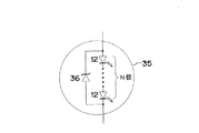
また、前記各実施例においては、電源回路14の負荷となる半導体光源として、LEDパッケージ34内に1個のLED12と1個のツェナーダイオード36を収納したものについて述べたが、図4に示すように、LEDパッケージ35内に複数個(N個)のLED12を互いに直列接続したものを収納し、N個直列接続されたLED12の両端にツェナーダイオード36を並列接続したものを半導体光源として用いることができる。この場合、ツェナーダイオード36として、N個のLED12のフォワード電圧の総和よりも大きいツェナー電圧を有するものを用いることで、前記各実施例と同様の効果を奏することができる。
In each of the above-described embodiments, a semiconductor light source serving as a load of the
また、電源回路14の負荷となる半導体光源を構成するに際しては、図5に示すように、複数個(N個)直列接続されたLEDパッケージ34またはLEDパッケージ35の一端側を電源回路14の出力端子30に接続し、他端側を抵抗R1を介して電源回路14の出力端子32に接続する構成を採用することもできる。
When a semiconductor light source serving as a load of the
10 車両用灯具の点灯制御回路
12 LED
14 電源回路
22、24 入力端子
30、32 出力端子
34、35 LEDパッケージ
36 ツェナーダイオード
38 外部接続端子
42、44、46 電圧観察用端子
48 電圧低下検出回路
50 PNPトランジスタ
52、54 NPNトランジスタ
10 Lighting control circuit for
14
Claims (4)
Priority Applications (3)
| Application Number | Priority Date | Filing Date | Title |
|---|---|---|---|
| JP2004271201A JP4771354B2 (en) | 2004-09-17 | 2004-09-17 | Lighting control circuit for vehicular lamp |
| US11/225,730 US7274150B2 (en) | 2004-09-17 | 2005-09-13 | Lighting control circuit for vehicle lighting equipment |
| DE102005044437A DE102005044437B4 (en) | 2004-09-17 | 2005-09-16 | Lighting control circuit for vehicle lighting equipment |
Applications Claiming Priority (1)
| Application Number | Priority Date | Filing Date | Title |
|---|---|---|---|
| JP2004271201A JP4771354B2 (en) | 2004-09-17 | 2004-09-17 | Lighting control circuit for vehicular lamp |
Publications (2)
| Publication Number | Publication Date |
|---|---|
| JP2006086413A JP2006086413A (en) | 2006-03-30 |
| JP4771354B2 true JP4771354B2 (en) | 2011-09-14 |
Family
ID=36011851
Family Applications (1)
| Application Number | Title | Priority Date | Filing Date |
|---|---|---|---|
| JP2004271201A Expired - Fee Related JP4771354B2 (en) | 2004-09-17 | 2004-09-17 | Lighting control circuit for vehicular lamp |
Country Status (3)
| Country | Link |
|---|---|
| US (1) | US7274150B2 (en) |
| JP (1) | JP4771354B2 (en) |
| DE (1) | DE102005044437B4 (en) |
Families Citing this family (36)
| Publication number | Priority date | Publication date | Assignee | Title |
|---|---|---|---|---|
| JP2007200610A (en) * | 2006-01-24 | 2007-08-09 | Koito Mfg Co Ltd | Lighting control device of vehicular lamp |
| US7729098B2 (en) | 2006-03-24 | 2010-06-01 | Ics Triplex Technology Limited | Overload protection method |
| US7688560B2 (en) | 2006-03-24 | 2010-03-30 | Ics Triplex Technology Limited | Overload protection method |
| US7747405B2 (en) * | 2006-03-24 | 2010-06-29 | Ics Triplex Technology Ltd. | Line frequency synchronization |
| US7476891B2 (en) * | 2006-03-24 | 2009-01-13 | Ics Triplex Technology, Ltd. | Fault detection method and apparatus |
| US8166362B2 (en) * | 2006-03-24 | 2012-04-24 | Rockwell Automation Limited | Fault detection method and apparatus for analog to digital converter circuits |
| US7613974B2 (en) * | 2006-03-24 | 2009-11-03 | Ics Triplex Technology Limited | Fault detection method and apparatus |
| US7504975B2 (en) * | 2006-03-24 | 2009-03-17 | Ics Triplex Technology Limited | Method and apparatus for output current control |
| ATE463066T1 (en) * | 2006-03-24 | 2010-04-15 | Ics Triplex Technology Ltd | OVERLOAD PROTECTION METHOD |
| DE102006018575A1 (en) * | 2006-04-21 | 2007-10-25 | Tridonicatco Gmbh & Co. Kg | Error detection of LEDs |
| TWI297223B (en) * | 2006-04-25 | 2008-05-21 | Gigno Technology Co Ltd | Package module of light emitting diode |
| FR2901956A1 (en) * | 2006-06-06 | 2007-12-07 | Lyracom Sarl | Light source`s e.g. incandescent lamp, LED controlling method for e.g. lantern, involves detecting malfunctioning of LEDs, and short-circuiting defective LED or group of LEDs in series comprising defective LED by bias of derivation |
| DE102006031679A1 (en) * | 2006-07-08 | 2008-01-10 | Hella Kgaa Hueck & Co. | Circuit arrangement for the electrical control of a motor vehicle headlight |
| JP5192672B2 (en) * | 2006-08-28 | 2013-05-08 | パナソニック株式会社 | LED unit |
| DE602006008961D1 (en) * | 2006-10-23 | 2009-10-15 | Alcatel Lucent | Safe opto-electronic failure detection for high-performance light-emitting diodes |
| CN101207951A (en) * | 2006-12-22 | 2008-06-25 | 泰兴玩具(深圳)有限公司 | Light-emitting diode lamp string with conducting insure measures |
| JP2008251320A (en) * | 2007-03-30 | 2008-10-16 | Ichikoh Ind Ltd | Lighting circuit for vehicular lighting fixture |
| DE102007024784B4 (en) * | 2007-05-26 | 2010-12-16 | Automotive Lighting Reutlingen Gmbh | Circuit arrangement, in particular for motor vehicle headlights and motor vehicle lights |
| TWM337680U (en) * | 2007-11-22 | 2008-08-01 | Everlight Electronics Co Ltd | Circuit apparatus for LEDs |
| WO2009112997A1 (en) * | 2008-03-13 | 2009-09-17 | Philips Intellectual Property & Standards Gmbh | Lighting apparatus on transparent substrate |
| US7755293B2 (en) * | 2008-06-19 | 2010-07-13 | Yazaki North America, Inc. | Method for protecting a lamp circuit and related wiring |
| CN102333677B (en) * | 2009-02-25 | 2014-12-24 | 三菱电机株式会社 | Headlamp light source-lighting device, alarm device and communication device |
| JP2010199522A (en) * | 2009-02-27 | 2010-09-09 | Toshiba Lighting & Technology Corp | Led lighting device |
| DE102010003506B4 (en) | 2009-04-09 | 2019-09-26 | Tridonic Jennersdorf Gmbh | LED cluster circuit with fault detection, LED light and lighting system |
| JP5537286B2 (en) * | 2010-06-28 | 2014-07-02 | パナソニック株式会社 | LED lighting device |
| US8513955B2 (en) * | 2010-09-28 | 2013-08-20 | Tyco Electronics Corporation | SSL budgeting and coding system for lighting assembly |
| DE102010049716A1 (en) | 2010-10-26 | 2012-04-26 | Automotive Lighting Reutlingen Gmbh | Composite of an on-board control unit and at least one light control device of a motor vehicle |
| JP5771775B2 (en) * | 2010-12-21 | 2015-09-02 | パナソニックIpマネジメント株式会社 | Lighting device, lamp and vehicle using the same |
| US8723427B2 (en) | 2011-04-05 | 2014-05-13 | Abl Ip Holding Llc | Systems and methods for LED control using on-board intelligence |
| JP5898478B2 (en) * | 2011-12-06 | 2016-04-06 | 株式会社小糸製作所 | Vehicle lighting |
| CN104061467A (en) * | 2014-03-31 | 2014-09-24 | 中山市新邦照明电器有限公司 | Novel LED lamp |
| WO2016075754A1 (en) * | 2014-11-11 | 2016-05-19 | 新電元工業株式会社 | Lighting control method and lighting control apparatus |
| FR3044167B1 (en) * | 2015-11-20 | 2018-01-05 | Commissariat A L'energie Atomique Et Aux Energies Alternatives | OPTOELECTRONIC LIGHT EMITTING DIODE DEVICE COMPRISING AT LEAST ONE ZENER DIODE |
| CN106427768B (en) * | 2016-10-14 | 2019-03-26 | 武汉通畅汽车电子照明有限公司 | A kind of lamp control device for the direct-injection type turn signal lamp showing battery capacity |
| CN106427767B (en) * | 2016-10-14 | 2018-10-30 | 武汉通畅汽车电子照明有限公司 | A kind of lamp control device of the LED location lamp of display battery capacity |
| DE102018120428A1 (en) * | 2018-08-22 | 2020-02-27 | HELLA GmbH & Co. KGaA | LED lighting device and motor vehicle |
Family Cites Families (15)
| Publication number | Priority date | Publication date | Assignee | Title |
|---|---|---|---|---|
| JPS622266U (en) * | 1985-06-20 | 1987-01-08 | ||
| JPH0194694U (en) * | 1987-12-15 | 1989-06-22 | ||
| JPH01113294U (en) * | 1988-01-25 | 1989-07-31 | ||
| JPH1187774A (en) * | 1997-07-09 | 1999-03-30 | Nichia Chem Ind Ltd | Led display device and semiconductor device |
| JPH11331494A (en) | 1998-05-08 | 1999-11-30 | Canon Inc | Contact type image sensor |
| JP2000033729A (en) | 1998-07-16 | 2000-02-02 | Hitachi Cable Ltd | Light emitting diode array |
| DE19841490B4 (en) | 1998-09-10 | 2005-06-30 | Infineon Technologies Ag | Circuit arrangement for protecting a series connection of at least two light-emitting diodes before failure |
| JP2000208817A (en) * | 1999-01-14 | 2000-07-28 | Tokimec Inc | Light source device |
| US6153980A (en) * | 1999-11-04 | 2000-11-28 | Philips Electronics North America Corporation | LED array having an active shunt arrangement |
| JP2002025784A (en) * | 2000-04-28 | 2002-01-25 | Takashi Ishizawa | Led-lighting circuit |
| GB0204212D0 (en) * | 2002-02-22 | 2002-04-10 | Oxley Dev Co Ltd | Led drive circuit |
| JP2004009826A (en) | 2002-06-05 | 2004-01-15 | Koito Mfg Co Ltd | Lighting fixture apparatus for vehicle |
| JP4236894B2 (en) | 2002-10-08 | 2009-03-11 | 株式会社小糸製作所 | Lighting circuit |
| JP3789428B2 (en) * | 2002-12-06 | 2006-06-21 | 星和電機株式会社 | Light emitting device |
| JP2004228498A (en) * | 2003-01-27 | 2004-08-12 | Denso Corp | Light-emitting diode |
-
2004
- 2004-09-17 JP JP2004271201A patent/JP4771354B2/en not_active Expired - Fee Related
-
2005
- 2005-09-13 US US11/225,730 patent/US7274150B2/en active Active
- 2005-09-16 DE DE102005044437A patent/DE102005044437B4/en not_active Expired - Fee Related
Also Published As
| Publication number | Publication date |
|---|---|
| US7274150B2 (en) | 2007-09-25 |
| JP2006086413A (en) | 2006-03-30 |
| US20060061303A1 (en) | 2006-03-23 |
| DE102005044437A1 (en) | 2006-03-30 |
| DE102005044437B4 (en) | 2007-01-04 |
Similar Documents
| Publication | Publication Date | Title |
|---|---|---|
| JP4771354B2 (en) | Lighting control circuit for vehicular lamp | |
| JP2006210219A (en) | Lighting control circuit of vehicular lighting fixture | |
| JP4914988B2 (en) | Control circuit for LED array and corresponding operating method | |
| JP4094477B2 (en) | Vehicle lighting | |
| US7888876B2 (en) | Lighting control for vehicle lighting device | |
| US8207675B2 (en) | Vehicle lamp | |
| JP2007200610A (en) | Lighting control device of vehicular lamp | |
| US7893622B2 (en) | Circuit apparatus of LED vehicle lamp | |
| JP2007161012A (en) | Vehicular light emission device | |
| JP2009525617A (en) | Temperature controlled LED array | |
| JP4244154B2 (en) | Vehicle lighting | |
| JP2004119422A (en) | Light emitting device drive circuit | |
| CN111556987B (en) | Multi-output load driving device | |
| JP6173874B2 (en) | Vehicle lighting | |
| JP2014241202A (en) | Led lighting device for vehicular lamp fitting | |
| JP6421618B2 (en) | LED module and LED lighting device | |
| JP5335643B2 (en) | Vehicle lighting | |
| JP2006288049A (en) | Load control circuit, current control circuit, and load control system | |
| KR20180035727A (en) | Constant current chip embedding led package module for vehicle | |
| JP6594590B2 (en) | In-vehicle lighting system | |
| JP6249555B2 (en) | Vehicle lighting | |
| JP2007142139A (en) | Led drive control unit | |
| KR102284059B1 (en) | Non-polar led package integrated with driver ic and led chip | |
| KR200396433Y1 (en) | Device of displaying broken fuse | |
| JP7275576B2 (en) | vehicle lamp |
Legal Events
| Date | Code | Title | Description |
|---|---|---|---|
| A621 | Written request for application examination |
Free format text: JAPANESE INTERMEDIATE CODE: A621 Effective date: 20070530 |
|
| A977 | Report on retrieval |
Free format text: JAPANESE INTERMEDIATE CODE: A971007 Effective date: 20090929 |
|
| A131 | Notification of reasons for refusal |
Free format text: JAPANESE INTERMEDIATE CODE: A131 Effective date: 20101208 |
|
| A521 | Request for written amendment filed |
Free format text: JAPANESE INTERMEDIATE CODE: A523 Effective date: 20110202 |
|
| TRDD | Decision of grant or rejection written | ||
| A01 | Written decision to grant a patent or to grant a registration (utility model) |
Free format text: JAPANESE INTERMEDIATE CODE: A01 Effective date: 20110615 |
|
| A01 | Written decision to grant a patent or to grant a registration (utility model) |
Free format text: JAPANESE INTERMEDIATE CODE: A01 |
|
| A61 | First payment of annual fees (during grant procedure) |
Free format text: JAPANESE INTERMEDIATE CODE: A61 Effective date: 20110615 |
|
| FPAY | Renewal fee payment (event date is renewal date of database) |
Free format text: PAYMENT UNTIL: 20140701 Year of fee payment: 3 |
|
| R150 | Certificate of patent or registration of utility model |
Free format text: JAPANESE INTERMEDIATE CODE: R150 Ref document number: 4771354 Country of ref document: JP Free format text: JAPANESE INTERMEDIATE CODE: R150 |
|
| LAPS | Cancellation because of no payment of annual fees |