JP4756947B2 - Information processing apparatus and method - Google Patents
Information processing apparatus and method Download PDFInfo
- Publication number
- JP4756947B2 JP4756947B2 JP2005228474A JP2005228474A JP4756947B2 JP 4756947 B2 JP4756947 B2 JP 4756947B2 JP 2005228474 A JP2005228474 A JP 2005228474A JP 2005228474 A JP2005228474 A JP 2005228474A JP 4756947 B2 JP4756947 B2 JP 4756947B2
- Authority
- JP
- Japan
- Prior art keywords
- task
- candidate
- input data
- processes
- information
- Prior art date
- Legal status (The legal status is an assumption and is not a legal conclusion. Google has not performed a legal analysis and makes no representation as to the accuracy of the status listed.)
- Expired - Fee Related
Links
Images


Classifications
-
- G—PHYSICS
- G06—COMPUTING; CALCULATING OR COUNTING
- G06F—ELECTRIC DIGITAL DATA PROCESSING
- G06F8/00—Arrangements for software engineering
- G06F8/20—Software design
Description
本発明は、複数の処理を連結した、実行可能なジョブフローの作成に関するものである。 The present invention relates to creation of an executable job flow in which a plurality of processes are connected.
文書データに施すべきFax送信、スキャナ及びプリントなどの処理を直列もしくは並列に組み合わせてジョブフローとして設定できるサービス処理装置が特許文献1によって開示されている。このサービス処理装置によれば、ネットワークに接続された機器を用いて、上記複数の処理を連携したジョブフローに従った文書データの処理を実行させることができる。
特許文献1のサービス処理装置は、ネットワークに接続された各機器に対して複数の処理を連携して直列処理及び並列処理することができる。しかしながら、並列処理後にさらに処理を続けるようなジョブフローを作成及び実行することはできなかった。例えば、特許文献1のサービス処理装置では、2つの処理を並列に実行して得られた2つの結果を入力とする処理を、当該並列処理の後段に接続したジョブフローを作成することは考慮されていない。
The service processing apparatus of
ジョブフローの作成に利用可能な処理には、複数の入力を必要とする処理が数多く存在することが予想される。そのような場合、タスク間の接続性を意識して複雑な並列処理を含んだジョブフローを作成することは困難である。 It is expected that there are many processes that require a plurality of inputs among processes that can be used to create a job flow. In such a case, it is difficult to create a job flow including complex parallel processing in consideration of connectivity between tasks.
本発明は、上記課題に鑑みてなされたものであり、並列処理後に、当該並列処理によって得られた複数の結果を用いた処理を続けるというような複雑なジョブフローを容易に作成可能にすることを目的とする。 The present invention has been made in view of the above problems, and makes it possible to easily create a complicated job flow in which processing using a plurality of results obtained by parallel processing is continued after parallel processing. With the goal.
上記の目的を達成するための本発明による情報処理装置は以下の構成を備えるすなわち、
複数の処理が連結されたフローを画面上で生成する情報処理装置であって、
フローを生成するために、第1の処理に後続する処理として第2の処理の接続が画面上で指示された場合、複数の処理の各々について入力データと出力データを規定するとともに各処理が属するカテゴリを示す処理情報が登録された登録手段に登録されている前記第1及び第2の処理の処理情報を参照することにより、前記第2の処理の入力データが不足するか否かを判定し、
不足すると判定された場合、前記第2の処理と同じカテゴリに属するとともに、不足している入力データを出力可能な処理を、前記登録手段に登録されている処理情報を参照して、前記登録手段に登録されている前記複数の処理の中から候補処理として取得し、
取得した候補処理を画面上に提示し、
提示した候補処理のうちの一つを選択する操作に応じて、選択された候補処理を前記第2の処理の前段の処理として接続して画面上に表示する。
In order to achieve the above object, an information processing apparatus according to the present invention comprises the following arrangement:
An information processing apparatus for generating a flow in which a plurality of processes are connected on a screen ,
In order to generate a flow, when connection of the second process is instructed on the screen as a process subsequent to the first process, input data and output data are defined for each of the plurality of processes, and each process belongs by referring to the processing information of the first and second processing process information indicating a category is registered in the registration means is registered, it determines whether the input data of the second process is insufficient ,
If it is determined that there is a shortage, a process that belongs to the same category as the second process and that can output the missing input data is referred to the process information registered in the registration means, and the registration means Obtained as a candidate process from the plurality of processes registered in
The acquired candidate process presented on the screen,
In response to an operation of selecting one of the presented candidate processes, the selected candidate process is connected as a process preceding the second process and displayed on the screen .
また、上記の目的を達成するための本発明の他の態様による情報処理装置は以下の構成を備える。すなわち、
複数の処理が連結されたフローを画面上で生成する情報処理装置であって、
フローを生成するために、第1の処理に後続する処理として第2の処理の接続が画面上で指示された場合、複数の処理の各々について入力データと出力データを規定するとともに各処理が属するカテゴリを示す処理情報とカテゴリの階層構造を示す階層情報とが登録された登録手段に登録されている前記第1及び第2の処理の処理情報を参照することにより、前記第2の処理の入力データが不足するか否かを判定し、
不足すると判定された場合、前記第2の処理と同じカテゴリまたは該カテゴリの上位階層のカテゴリに属し、不足している入力データを出力可能な処理を、前記登録手段に登録されている処理情報と階層情報を参照して、前記登録手段に登録されている前記複数の処理の中から候補処理として取得し、
取得された候補処理を画面上に提示し、
提示した候補処理のうちの一つを選択する操作に応じて、選択された候補処理を前記第2の処理の前段の処理として接続して画面上に表示する。
An information processing apparatus according to another aspect of the present invention for achieving the above object has the following configuration. That is,
An information processing apparatus for generating a flow in which a plurality of processes are connected on a screen ,
In order to generate a flow, when connection of the second process is instructed on the screen as a process subsequent to the first process, input data and output data are defined for each of the plurality of processes, and each process belongs The input of the second process by referring to the process information of the first and second processes registered in the registration means in which the process information indicating the category and the hierarchy information indicating the hierarchical structure of the category are registered. it is determined whether or not the data is insufficient,
If it is determined that there is a shortage, a process that belongs to the same category as the second process or a category in a higher hierarchy of the category and that can output the deficient input data is processed information registered in the registration unit. Referring to the hierarchy information, obtaining as a candidate process from the plurality of processes registered in the registration means,
The obtained candidate process provides suggestions on a screen,
In response to an operation of selecting one of the presented candidate processes, the selected candidate process is connected as a process preceding the second process and displayed on the screen .
また、上記の目的を達成するための本発明による情報処理方法は、
複数の処理が連結されたフローを生成する情報処理装置による情報処理方法であって、
フローを生成するために、第1の処理に後続する処理として第2の処理の接続が指示された場合、前記情報処理装置のコンピュータが、複数の処理の各々について入力データと出力データを規定するとともに各処理が属するカテゴリを示す処理情報が登録された登録手段に登録されている前記第1及び第2の処理の処理情報を参照することにより、前記第2の処理の入力データが不足するか否かを判定する判定工程と、
前記判定工程で不足すると判定された場合、前記情報処理装置のコンピュータが、前記第2の処理と同じカテゴリに属するとともに、不足している入力データを出力可能な処理を、前記登録手段に登録されている処理情報を参照して、前記登録手段に登録されている前記複数の処理の中から候補処理として取得する取得工程と、
前記情報処理装置のコンピュータが、前記取得工程で取得した候補処理を表示装置に表示させる提示工程と、
前記情報処理装置のコンピュータが、前記提示工程で提示された候補処理のうちの一つを選択する操作に応じて、選択された候補処理を前記第2の処理の前段の処理として接続する接続工程とを備える。
An information processing method according to the present invention for achieving the above object is as follows:
An information processing method by an information processing apparatus that generates a flow in which a plurality of processes are connected,
In order to generate a flow, when connection of the second process is instructed as a process subsequent to the first process, the computer of the information processing apparatus defines input data and output data for each of the plurality of processes. Whether the input data of the second process is insufficient by referring to the process information of the first and second processes registered in the registration means in which the process information indicating the category to which each process belongs is registered A determination step of determining whether or not,
If it is determined in the determination step that the information processing apparatus is insufficient, the computer of the information processing apparatus belongs to the same category as the second process, and a process capable of outputting the insufficient input data is registered in the registration unit. An acquisition step of acquiring as a candidate process from among the plurality of processes registered in the registration means;
A presentation step in which the computer of the information processing device displays the candidate process acquired in the acquisition step on a display device;
A connection step in which the computer of the information processing apparatus connects the selected candidate process as a process preceding the second process in response to an operation of selecting one of the candidate processes presented in the presenting step. With.
また、上記の目的を達成するための本発明の他の態様による情報処理方法は、
複数の処理が連結されたフローを生成する情報処理装置による情報処理方法であって、
フローを生成するために、第1の処理に後続する処理として第2の処理の接続が指示された場合、前記情報処理装置のコンピュータが、複数の処理の各々について入力データと出力データを規定するとともに各処理が属するカテゴリを示す処理情報とカテゴリの階層構造を示す階層情報とが登録された登録手段に登録されている前記第1及び第2の処理の処理情報を参照することにより、前記第2の処理の入力データが不足するか否かを判定する判定工程と、
前記判定工程で不足すると判定された場合、前記情報処理装置のコンピュータが、前記第2の処理と同じカテゴリまたは該カテゴリの上位階層のカテゴリに属し、不足している入力データを出力可能な処理を、前記登録手段に登録されている処理情報と階層情報を参照して、前記登録手段に登録されている前記複数の処理の中から候補処理として取得する取得工程と、
前記情報処理装置のコンピュータが、前記取得工程で取得した候補処理を表示装置に表示させる提示工程と、
前記情報処理装置のコンピュータが、前記提示工程で提示された候補処理のうちの一つを選択する操作に応じて、選択された候補処理を前記第2の処理の前段の処理として接続する接続工程とを備える。
An information processing method according to another aspect of the present invention for achieving the above-described object is as follows:
An information processing method by an information processing apparatus that generates a flow in which a plurality of processes are connected,
In order to generate a flow, when connection of the second process is instructed as a process subsequent to the first process, the computer of the information processing apparatus defines input data and output data for each of the plurality of processes. And by referring to the processing information of the first and second processes registered in the registration means in which the processing information indicating the category to which each process belongs and the hierarchical information indicating the hierarchical structure of the category are registered. A determination step of determining whether or not the input data of the process 2 is insufficient;
When it is determined in the determination step that the information processing apparatus is insufficient, the computer of the information processing apparatus belongs to the same category as the second process or a category in an upper hierarchy of the category, and is capable of outputting the input data that is insufficient Obtaining the candidate process from among the plurality of processes registered in the registration unit with reference to the process information and hierarchy information registered in the registration unit;
A presentation step in which the computer of the information processing device displays the candidate process acquired in the acquisition step on a display device;
A connection step in which the computer of the information processing apparatus connects the selected candidate process as a process preceding the second process in response to an operation of selecting one of the candidate processes presented in the presenting step. With.
本発明によれば、並列処理後に、当該並列処理によって得られた複数の結果を用いた処理を続けるというような複雑なジョブフローを容易に作成することが可能になる。 According to the present invention, it is possible to easily create a complicated job flow in which processing using a plurality of results obtained by parallel processing is continued after parallel processing.
以下、添付の図面を参照して本発明の好適な実施形態を説明する。 Hereinafter, preferred embodiments of the present invention will be described with reference to the accompanying drawings.
まず、本実施形態のシステム構成、およびアプリケーション構成について説明する。 First, the system configuration and application configuration of this embodiment will be described.
〈システム構成〉
図1は実施形態1に係るタスク連携処理システムの全体構成を図示している。タスク連携処理システムは、印刷処理装置から、印刷処理装置のタスクを含むさまざまなタスクを連携実行可能とするシステムである。
<System configuration>
FIG. 1 illustrates the overall configuration of a task cooperation processing system according to the first embodiment. The task cooperation processing system is a system that enables various tasks including a task of a print processing apparatus to be executed in cooperation from a print processing apparatus.
なお、本実施形態におけるタスクとは、文書データに対して実行可能な処理のことを示している。たとえば、印刷処理装置のタスクとしては、文書データのコピー、スキャン、Fax送信、印刷処理装置内のハードディスクへの保存、メール送信等を挙げることができる。もちろん、本発明に適用可能なタスクはこれらに限定されるものではない。また、本タスク連携処理システムでは、上記タスクを提供する印刷処理装置の他、さまざまなタスクを提供可能な複数のアプリケーションとも連携可能である。本実施形態では、タスクを実行可能な印刷処理装置やアプリケーション実行する情報処理装置をタスク処理装置と定義する。なお、タスクを実行可能なアプリケーションを実行する装置としては、例えばパーソナルコンピュータ等の情報処理装置が挙げられる。 Note that a task in the present embodiment indicates a process that can be executed on document data. For example, the tasks of the print processing apparatus can include copying document data, scanning, fax transmission, saving to a hard disk in the print processing apparatus, and mail transmission. Of course, tasks applicable to the present invention are not limited to these. In addition, in this task cooperation processing system, it is possible to cooperate with a plurality of applications that can provide various tasks in addition to the print processing apparatus that provides the above tasks. In this embodiment, a print processing apparatus that can execute a task and an information processing apparatus that executes an application are defined as a task processing apparatus. An example of an apparatus that executes an application that can execute a task is an information processing apparatus such as a personal computer.
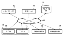
タスク連携処理システムは、管理サーバ11、クライアントPC12、タスク一覧DB13、アプリA14、アプリB15、印刷処理装置A16及び印刷処理装置B17を含み、それぞれネットワーク18で接続されている。なお、アプリA14は情報処理装置19によって実行されるアプリケーションAを、アプリB15は情報処理装置19によって実行されるアプリケーションBを表している。また、アプリケーション及び印刷処理装置の数は図示のものに限定されるものではない。また、タスク一覧DB13はアプリケーション毎に用意するもしくは印刷処理装置のタスク管理とは別にするなど、その形態に関しては何等限定されるものではない。また、アプリA14及びアプリB15を実行する情報処理装置は別々の装置であってもよい。ただし、以下では、図1に示されるように、2つのアプリケーション(アプリA14、アプリB15)及び2台の印刷処理装置(印刷処理装置A16、印刷処理装置B17)が接続されているタスク連携処理システムを用いて説明する。
The task cooperation processing system includes a
管理サーバ11はアプリA14、アプリB15、印刷処理装置A16、印刷処理装置B17の各タスク処理装置の管理を行い、各タスク処理装置の実行可能なタスクをタスク一覧DB13で管理する。また、クライアントPC12は、タスク一覧DB13に登録されたタスクから実行可能な所望のタスクを管理サーバ11を介して取得し、それらを用いてジョブフローを作成する。なお、ジョブフローは複数のタスクを組み合わせて得られる一連の処理を表している。ジョブフローとは、1つのジョブとして実行する単位、即ち、複数タスクを連続実行する単位である。作成されたジョブフローは管理サーバ11上で管理され、印刷処理装置A16や印刷処理装置B17から実行することができる。
The
〈動作フロー〉
図2A、図2Bは新規アプリケーション(ジョブフローに利用可能なタスクを含むアプリケーション)の追加からジョブフローの実行までの本実施形態1のタスク連携処理システムの動作フローを示している。なお、図2AはクライアントPC12を介してアプリケーションの登録を行う系を示し、図2BはクライアントPC12を介さずにアプリケーションの登録を行う系を示している。
<Operation flow>
2A and 2B show an operation flow of the task cooperation processing system according to the first embodiment from addition of a new application (an application including a task that can be used in the job flow) to execution of the job flow. 2A shows a system for registering an application via the
まず、クライアントPC12を介して、アプリケーションの登録を行う場合(図2A)を、アプリB15が新規追加されたものとして説明する。クライアントPC12は新規追加されたアプリB15のタスクインターフェース(I/F)情報をアプリB15から取得(21)する。タスクI/F情報には例えば当該タスクが必要とする入力データ、当該タスクの実行により得られる出漁kデータの定義が含まれている。次にクライアントPC12から管理サーバ11に対して、取得したタスクI/F情報を含めたアプリ情報を送信(22)し、当該アプリの登録を要求する。アプリ情報とその登録要求を受け取った管理サーバ11は、タスク一覧DB13へアプリB15のタスク情報の登録(23)を行う。この際、管理サーバ11はタスクI/F情報にもとづいて図3で後述するようなタスク定義情報を生成し、これをタスク一覧DB13に登録する。こうしてアプリB15によって実行可能なタスクがタスク一覧DB13に登録される。
First, a case where an application is registered via the client PC 12 (FIG. 2A) will be described assuming that the application B15 is newly added. The
以上のような登録処理が完了した後、アプリB15のタスクを含むジョブフローを作成することができるようになる。ジョブフローの作成はクライアントPC12により行われる。ジョブフローの作成において、クライアントPC12は、管理サーバ11を介してタスク一覧DB13に登録されているタスク一覧を参照(24)し、所望のタスクを組み合わせてジョブフローの作成及び登録(25)を行う。登録されたジョブフローは管理サーバ11上で管理される。
After the registration process as described above is completed, a job flow including the task of the application B15 can be created. The job flow is created by the
ジョブフローの登録完了後、管理サーバ11の管理する印刷処理装置からジョブフローを実行することができる。例えば、印刷処理装置A16は管理サーバ11で管理されているジョブフロー一覧を参照(26)することができる。ジョブフローを実行させたいユーザ20は、印刷処理装置B16から所望のジョブフローを選択し、これを実行(27)させる。ジョブフローの実行依頼を受け取った管理サーバ11はジョブフロー内のタスクを実行可能なタスク処理装置へタスク実行依頼(28)を行い、選択されたジョブフローを実行する。なお、ジョブフロー内のタスクをどのタスク処理装置で実行するか、タスク名等はタスク定義情報としてタスク一覧DB13内で管理されるものとするが、その詳細は図3で説明する。
After the job flow registration is completed, the job flow can be executed from the print processing apparatus managed by the
一方、クライアントPC12を介さずに、アプリケーションの登録を行う場合は図2Bのように動作する。図2Aとの差異は、管理サーバ11が新規追加アプリケーション(アプリB15)のタスクI/F情報を、直接アプリB15から取得(29)する点である。従って、図2Bでは、アプリB15からクライアントPC12へのタスクI/F情報の登録(21)とクライアントPC12から管理サーバ11へのアプリ登録(22)は存在しない。その他の動作フローに関しては図2Aと同様である。
On the other hand, when registering an application without using the
〈タスク定義情報〉
図3は本実施形態において、タスク一覧DB13へタスク情報を登録(タスク登録(23))する際のタスク定義情報を図示している。タスク定義情報は、タスク名31、タスク処理装置32、属性情報33、入力データ34、出力データ35を含む。タスク名31は、当該タスクのタスク名を表す。タスク処理装置32は当該タスクを実行可能なタスク処理装置を示す。属性情報33は、当該タスクを実行する際に必要となる属性情報を表している。属性情報33について、帳票のフォームとその帳票フォームに差し込むマスタデータを選択し、帳票合成後に帳票を出力するアプリケーションを例に説明する。このアプリケーションでは、帳票の出力フォーマットに、PDFとして出力、アプリケーション独自の帳票フォーマットで出力の2パターンが存在する。また帳票を出力する場合には、このどちらかを必ず指定する必要がある。つまり、帳票出力を実行する場合には、出力フォーマットを指定しなければタスクを実行することができないが、このタスクを実行するために指定する出力フォーマットが帳票出力タスクの属性情報33となる。指定時には属性情報33の欄にPDF出力もしくは独自フォーマット出力のどちらかが指定されることになる。入力データ34は、当該タスクを実行するのに必要な入力データを表す。出力データ35は、当該タスクの実行により出力される出力データを表す。入力データ34、出力データ35は、それぞれ複数種類のデータを定義することができる。なお、タスク定義情報の記述形式に関しては特に限定されるものではない。
<Task definition information>
FIG. 3 illustrates task definition information when task information is registered in the task list DB 13 (task registration (23)) in the present embodiment. The task definition information includes a
〈ジョブフロー定義情報〉
次に、クライアントPC12によって生成され、管理サーバ11に登録されるジョブフローの定義情報(ジョブフロー定義情報)について説明する。図4A,図4Bは本実施形態によるジョブフロー定義情報を説明する図である。
<Job flow definition information>
Next, job flow definition information (job flow definition information) generated by the
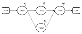
図4Aは、本実施形態によるジョブフロー定義情報を説明するために、ジョブフロー定義情報を模式的に示したものである。図4Aの例では、タスク41(Task1)を実行後、タスク42(Task2)及びタスク43(Task3)を並列処理し、その後、タスク44(Task4)を実行して終了するジョブフローとなっている。 FIG. 4A schematically shows job flow definition information in order to explain job flow definition information according to the present embodiment. In the example of FIG. 4A, after executing the task 41 (Task1), the task 42 (Task2) and the task 43 (Task3) are processed in parallel, and then the task 44 (Task4) is executed and terminated. .
図4Bは図4Aに例示したジョブフロー定義情報をXML形式で示したものである。本実施形態では、タスクの実行順序を定義するため、XML内にtaskタグが用意され、該タスクの前に実行するタスク名をbeforeタグに、該タスクの後に実行するタスク名をafterタグに記述される。また、タスク定義情報内にタスクの属性に関する情報(図3の属性情報)が定義されている場合は、propertyタグ内に該当する情報を記述する。上記定義をジョブフロー内に定義されているタスク分記述することによってジョブフロー定義情報が完成する。なおジョブフロー定義情報の記述は、タスク間の前後関係を明記できるものであれば、上記のようなXML形式に限定するものではない。 FIG. 4B shows the job flow definition information illustrated in FIG. 4A in XML format. In this embodiment, in order to define the execution order of tasks, a task tag is prepared in XML, the task name to be executed before the task is described in the before tag, and the task name to be executed after the task is described in the after tag. Is done. Further, when information related to task attributes (attribute information in FIG. 3) is defined in the task definition information, the corresponding information is described in the property tag. The job flow definition information is completed by describing the above definitions for the tasks defined in the job flow. The description of the job flow definition information is not limited to the XML format as described above as long as the context between tasks can be clearly specified.
〈タスクのアイコン表示〉
図5Aは本発明におけるタスク定義情報からタスクをアイコン表示した例を図示している。図3で説明したように本発明におけるタスク定義情報は、タスクの実行に必要な入力データ及びタスクを実行した結果の出力データを有しており、アイコンにはこれらの情報が反映されている。本タスク連携処理システムではジョブフローの作成を容易に行うため、ジョブフロー作成エディタ上でのタスクを図5Aのようなアイコンで示す。そして、それぞれのタスクは図5Bに示すような意味をもつ。例えば、TaskAはタスク定義情報において入力データの定義はなく、出力データに「PDFデータ」が定義されている。従って、図5AのTaskAアイコン51に示されるように、出力側のみに、データ内容(PDFデータ)とともに矢印が示される。また、TaskBは、図5Bに示されるように、入力データがPDFデータ、出力データがTXTデータとなっている。よって、図5AのTaskBアイコン52に示されるように、入力側と出力側にデータ内容と矢印が示される。同様に、TaskCでは2種類の入力データが定義されているので、TaskCアイコン53では入力側に2つの矢印がデータ内容とともに示されている。本実施形態では、図6で後述するジョブフロー作成エディタにより、管理者もしくは権限をもつユーザがこれらのアイコンを用いてジョブフローを作成する。以下、タスクを表すアイコンをタスクアイコンと称する。
<Task icon display>
FIG. 5A shows an example in which a task is displayed as an icon from the task definition information in the present invention. As described with reference to FIG. 3, the task definition information in the present invention has input data necessary for executing the task and output data resulting from the execution of the task, and these information are reflected in the icons. In this task cooperation processing system, in order to easily create a job flow, tasks on the job flow creation editor are indicated by icons as shown in FIG. 5A. Each task has a meaning as shown in FIG. 5B. For example, TaskA has no definition of input data in task definition information, and “PDF data” is defined as output data. Therefore, as indicated by the
〈ジョブフロー作成エディタ〉
図6A,図6Bは本実施形態におけるジョブフロー作成エディタのユーザインターフェース例を示す図である。ジョブフロー作成エディタのユーザインターフェースは、タスク一覧ウィンドウ61及びワークスペースウィンドウ67から構成され、マウスカーソル60を用いて操作される。
<Job flow creation editor>
6A and 6B are diagrams showing examples of the user interface of the job flow creation editor in the present embodiment. The user interface of the job flow creation editor includes a
タスク一覧ウィンドウ61は、操作時にアクティブなタスク処理装置内のタスク一覧を表示するためのアクティブサブウィンドウ62と、非アクティブなタスク処理装置の一覧を表示するための非アクティブサブウィンドウ63から構成される。また、本タスク連携処理システムで利用可能なタスク処理装置がそれぞれアイコンで表示されており、アイコン64が印刷装置A16に、アイコン65がアプリA14に、アイコン66がアプリB15にそれぞれ対応している。即ち、図6Aでは、印刷処理装置A16、アプリA14、アプリB15のタスク処理装置が利用可能であることが示されている。
The
ジョブフロー作成エディタ起動時にアクティブサブウィンドウ62内に表示されるタスク一覧は、あらかじめ設定されたタスク処理装置のタスクの一覧である。図6Aの例では印刷処理装置A16(アイコン64)がデフォルトに設定されている状態が示されている。また図6Aの例では、アクティブウインドウ62内にタスクアイコン51〜54が表示されており、印刷処理装置A16内にTaskA、TaskB、TaskC、TaskDの4つのタスクが存在していることを示している。
The task list displayed in the
ワークスペースウィンドウ67内は作成するジョブフロー名を入力するテキストフィールド68及びタスクを配置していくためのジョブフロー作成ウィンドウ69から構成される。
The
一方、図6Bでは、ジョブフロー作成時にアプリA14のアイコン65をクリックした後のジョブフロー作成エディタを図示している。選択されたアプリA14(アイコン65)のもつタスク一覧がアクティブサブウィンドウ62内に表示され、起動時にアクティブであった印刷処理装置A16のタスク一覧は非アクティブウィンドウ63内にデバイスアイコン64としてまとめて表示される。なお、タスクアイコン65−1〜65−3はアプリA14内に存在するタスクの一覧を示している。
On the other hand, FIG. 6B shows the job flow creation editor after the
以上のような構成を備えた本実施形態のタスク連携処理システムの動作について、以下、具体例を示しながら説明する。 The operation of the task cooperation processing system of the present embodiment having the above configuration will be described below with a specific example.
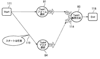
《例1》
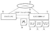
図7は例1によるタスク連携処理システムの概要を示す図である。クライアントPC72は図1のクライアントPC12に対応している。例1において、連携するアプリケーションはコンテンツ管理サーバ71、クライアントPC72から構成され、それぞれネットワーク73で接続されている。例えば、図7ではクライアントPC72とコンテンツ管理サーバ71で各々帳票に関するアプリケーションが動いており、そのサーバとクライアント上のアプリケーションが連携してタスクを形成している。なお、クライアントPC72或いはコンテンツ管理サーバ71が管理サーバ11を兼ねてもよい。
Example 1
FIG. 7 is a diagram showing an outline of the task cooperation processing system according to the first example. The
コンテンツ管理サーバ71は、コンテンツデータ74、マスタデータ75、フォームデータ76を管理している。コンテンツデータ74は、画像データやPDFカタログデータなどを登録したものである。マスタデータ75は、商品などの基本情報をテキストデータで登録したものである。フォームデータ76は、帳票データなどを作成するための雛型となる帳票テンプレートを登録したものである。コンテンツ管理サーバ71はクライアントPC72からマスタデータ及びフォームデータの指定(77)を入力として受け取り、マスタデータ及びフォームデータから帳票データを作成し、その帳票データを出力結果(78)としてクライアントPC72へ返す。即ち、例1において生成、実行されるジョブフローは、クライアントが所望するさまざまな帳票を容易に作成可能とするものである。
The
図8は例1において連携するアプリケーションに含まれるタスクの一部についてそれらのアイコン表示例を示す図である。図8には4つのタスクが例示されており、各タスクの入出力データは図14に示す通りである。例えば、フォーム選択タスク(Task1)はフォームデータを選択するタスクであり、タスクアイコン81はこれに対応するアイコンである。フォーム選択タスクには図14に示されるように0個の入力データと1個の出力データが存在する。従って、タスクアイコン81には、出力データのみが示されている。テキスト抽出タスク(Task2)はPDFカタログデータからテキストを抽出するタスクであり、タスクアイコン82がこれに対応する。テキスト抽出タスクには1つの入力データと1つの出力データが存在し、タスクアイコン82にはこの状態が明示されている。同様に、帳票合成タスク(Task3)はクライアントから指示されたマスタデータ及びフォームデータから帳票データを合成するタスクであり、タスクアイコン83がこのタスクに対応する。また、マスタ選択タスク(Task4)はマスタデータを選択するタスクであり、タスクアイコン84がこのタスクを表している。
FIG. 8 is a diagram showing an icon display example of a part of tasks included in an application linked in Example 1. FIG. 8 illustrates four tasks, and input / output data of each task is as shown in FIG. For example, the form selection task (Task1) is a task for selecting form data, and the
図9A,図9Bはタスクをカテゴライズするためのタスク定義情報を図示している。図9Aは本タスク連携処理システムで連携するアプリケーションのタスク定義情報を示している。連携するアプリケーションによっては、図3で説明したタスク定義情報91の付加情報としてカテゴリ情報92を設定可能である。この場合、例えば図4Bに示したXML記述において、categoryタグを設けてカテゴリ名を記述するようにすればよい。図9Bは、マスタ選択タスク84のタスク定義情報を図示している。図9Bでは、マスタ選択タスク84がアプリA(例1で連携するアプリケーション)の「帳票出力」カテゴリに属していることを示している。
9A and 9B illustrate task definition information for categorizing tasks. FIG. 9A shows task definition information of an application linked in the task linkage processing system. Depending on the linked application, the
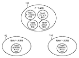
図10は図9A,図9Bのタスク定義情報により、図8で示したタスク等をカテゴライズした例を図示している。例1で利用可能な各タスクはそれぞれ「帳票出力」カテゴリ101と「カタログ登録」カテゴリ102にカテゴライズすることができる。「帳票出力」カテゴリ101には、帳票合成タスク、フォーム選択タスク、マスタ選択タスクが分類されている。また、テキスト抽出タスク、サムネイル作成タスク、ページ分割タスクが「カタログ登録」カテゴリ102に分類されている。
FIG. 10 shows an example in which the tasks shown in FIG. 8 are categorized by the task definition information shown in FIGS. 9A and 9B. Each task available in Example 1 can be categorized into a “form output”
図11A〜Cは、上述したジョブフロー作成エディタを用いた、例1におけるジョブフローの作成手順を図示している。例1では、図7で示すアプリケーションを使用し、帳票データを出力するまでの流れを定義したジョブフローを作成する。図11A〜Cは、ジョブフロー作成エディタのジョブフロー作成ウィンドウ69(図6)上での操作例を示している。 11A to 11C illustrate job flow creation procedures in Example 1 using the above-described job flow creation editor. In Example 1, the application shown in FIG. 7 is used to create a job flow that defines the flow until the form data is output. 11A to 11C show examples of operations on the job flow creation window 69 (FIG. 6) of the job flow creation editor.
ジョブフロー作成者は、ジョブフローの作成を開始し、例えばまず図11Aに示すようにタスクアイコンを配置する。タスクアイコンは、アクティブサブウィンドウ62に表示されたタスクアイコンをドラッグ&ドロップすることにより配置される。図11Aの例では、スタートアイコン111から開始し、フォーム選択タスクに対応するタスクアイコン81に続いて、帳票合成タスクに対応するタスクアイコン83が配置された状態が示されている。
The job flow creator starts creating a job flow, and first arranges task icons, for example, as shown in FIG. 11A. The task icon is arranged by dragging and dropping the task icon displayed in the
図11Bは、並列処理の合流を含むジョブフローの作成手順を図示している。タスクアイコン83には、入力データが2つ必要であることが示されている。従って図11Aに示されるように、タスクアイコン83が配置されると、これに対応する帳票合成タスクにはPDFデータ及びTXTデータの2つの入力データ必要であることがわかる。そのため、タスクアイコン83を配置した時点では、入力データがそろっておらず、タスクアイコン83(帳票合成タスク)に続くタスクを配置することができない。
FIG. 11B illustrates a procedure for creating a job flow including a confluence of parallel processes. The
そこで、複数の入力が必要なタスクのアイコンがジョブフロー作成ウィンドウ69(図6)上に配置された時点で、対応するタスクが入力として必要なデータを出力データにもつタスクの候補を表示(115)する。図11A、図11Bの例では、タスクアイコン83がジョブフロー作成ウィンドウ69上に配置された時点で、対応する帳票合成タスクが入力として必要なデータ114を出力データにもつタスクの候補が表示される。なお例1で候補として表示されるタスクは、帳票合成タスク83が必要とする入力データと同じデータ型を出力データにもつタスクでかつ該タスク83と同カテゴリに属するタスクとする。
Therefore, when the icons of tasks requiring a plurality of inputs are arranged on the job flow creation window 69 (FIG. 6), candidate tasks having the data necessary for the corresponding task as input are displayed (115). ) In the example of FIGS. 11A and 11B, when the
同カテゴリのタスクを候補として出力することによって、入出力のデータ型としては同じだが、実際にジョブフローとしては成立しないようなタスクが配置されることを回避できる。出力データが複数のタスクを連携するような場合は、処理実行後のデータを渡すだけなので特に後続するタスクに制限はない。これに対して、上述した帳票合成タスクのように複数の入力データを必要とする場合は、制限を設ける必要がある。すなわち、タスクの出力側に後段のタスクを接続する場合には、出力データの型の一致さえ見ればよいが、タスクの入力側にタスクを接続する場合にはカテゴリの一致まで考慮する必要がある。本例では、複数入力を必要とするタスクを含む、ジョブフローの作成に利用可能なタスクをカテゴライズして管理することにより、この制限を実現している。 By outputting tasks of the same category as candidates, it is possible to avoid arranging tasks that have the same input / output data type but are not actually established as job flows. When the output data links a plurality of tasks, there is no restriction on the succeeding task because only the data after processing is passed. On the other hand, when a plurality of input data is required as in the above-described form synthesis task, it is necessary to provide a restriction. In other words, when connecting a subsequent task to the output side of a task, it is only necessary to see the matching of the output data type, but when connecting a task to the input side of the task, it is necessary to consider even matching of categories. . In this example, this limitation is realized by categorizing and managing tasks that can be used to create a job flow, including tasks that require multiple inputs.
例えば、テキスト抽出タスクはその出力データがTXTデータであり、帳票合成タスクの入力データと同じデータ型であるが、カテゴリが異なるためジョブフローとして定義することができない。従って、テキスト抽出タスクに対応するタスクアイコン82はジョブフローとして定義することができず、図11Bに示されるように候補として表示されない。また、マスタ選択タスクは、その出力データが帳票合成タスクの入力データと同じデータ型(TXTデータ)であり、かつ同カテゴリとして管理されているタスクである。従って、図11Bに示されるように、マスタ選択タスクに対応するタスクアイコン84が候補として表示されることになる。なお、候補タスクに対応するタスクアイコンの表示は、図111Bのような破線によるものに限られず、所定色での表示、点滅表示等、候補タスクであることがユーザに認識できる形態とすればよい。
For example, the output data of the text extraction task is TXT data and has the same data type as the input data of the form synthesis task, but cannot be defined as a job flow because the category is different. Therefore, the
以上のように候補タスクの一覧が提示されると、ジョブフロー作成者は、帳票合成タスク(タスクアイコン83)を実行可能にするために必要な、所望のタスクを候補タスク一覧(図11Bではタスクアイコン84のみ)から選択することができる。候補タスク一覧から選択されたタスクアイコンは、タスクアイコン83で示される帳票合成タスクへ続くタスク(帳票合成タスクの前段のタスク)として配置される。例えば、タスクアイコン84(マスタ選択タスク)が選択されると、帳票合成タスクの前段に、フォーム選択タスクと並列に処理が実行されるようにマスタ選択タスクが配置され、図11Cに示されるようなジョブフローが生成されることになる。
When the list of candidate tasks is presented as described above, the job flow creator selects a desired task necessary for enabling the form synthesis task (task icon 83) to be executed (in FIG. 11B, a task list). From the
図11Cは並列処理の合流を含んだジョブフローを作成した結果を図示している。図11Cのジョブフローでは、タスクアイコン83後にEndアイコン118が接続されている。従って、フォーム選択、マスタ選択がなされた後、帳票合成タスクを実行した時点で当該ジョブフローによる処理は終了する。
FIG. 11C illustrates a result of creating a job flow including a confluence of parallel processing. In the job flow of FIG. 11C, an
なお、図11Bで示された候補タスク一覧から選択されたタスクが更に入力データを必要とするタスクであった場合は、上記と同様の手順で、当該選択されたタスクに接続され得る候補タスクが表示する。一方、選択されたタスクが入力データを必要としないタスクである場合は、選択されたタスクの実行開始地点を任意に設定することができる。図11Cの例では選択されたマスタ選択タスク(タスクアイコン84)は入力データを必要としない。図11Cでは、タスクアイコン84が示すマスタ選択タスクの実行開始地点がスタート地点に配置されている(119)。なお、このような実行開始地点の設定は、デフォルトでスタート時としておき、ユーザの操作指示により任意に設定できるようにしてもよいし、種々の変形が考えられる。
If the task selected from the candidate task list shown in FIG. 11B is a task that requires further input data, candidate tasks that can be connected to the selected task are processed in the same manner as described above. indicate. On the other hand, when the selected task is a task that does not require input data, the execution start point of the selected task can be arbitrarily set. In the example of FIG. 11C, the selected master selection task (task icon 84) does not require input data. In FIG. 11C, the execution start point of the master selection task indicated by the
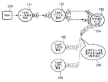
図12は本実施形態におけるジョブフロー作成エディタの全体処理のフローチャートを示している。 FIG. 12 shows a flowchart of the overall processing of the job flow creation editor in this embodiment.
ジョブフロー作成エディタが起動され処理が開始されると、ステップS1において、タスクがジョブフロー作成ウィンドウ69(図6)上に配置されたかどうかチェックする。タスクが配置されると、ステップS1からステップS2へ進み、配置されたタスクの入力データが不足しているかどうかをする。前段のタスクの出力データが配置されたタスクの入力データの全てを満たしていない場合、入力データが不足していると判定される。入力データが不足していない場合はステップS1へ戻る。一方、入力データが不足している場合は、ステップS3へ進み、図11Bにより上述したような候補タスクの表示を行い、ユーザにタスクを選択させる。その後、ステップS1へ戻り、上記の処理を繰り返す。図12に示される処理は、ジョブフローの作成終了が検出されるまで(本実施形態ではEndアイコンの配置が検出されるまで)繰り返される。Endアイコンが配置されると、ジョブフローの作成終了であるとして本処理を終了する。 When the job flow creation editor is activated and processing is started, in step S1, it is checked whether or not the task is arranged on the job flow creation window 69 (FIG. 6). When the task is arranged, the process proceeds from step S1 to step S2, and it is determined whether input data of the arranged task is insufficient. If the output data of the previous task does not satisfy all of the input data of the arranged task, it is determined that the input data is insufficient. If there is no shortage of input data, the process returns to step S1. On the other hand, if the input data is insufficient, the process proceeds to step S3, where the candidate tasks are displayed as described above with reference to FIG. 11B, and the user is allowed to select a task. Then, it returns to step S1 and repeats said process. The processing shown in FIG. 12 is repeated until the end of job flow creation is detected (in the present embodiment, the end icon arrangement is detected). When the End icon is arranged, it is determined that the job flow has been created, and the process is terminated.
図13は本実施形態におけるタスクの検索・表示・選択(図12のステップS3)の処理を示すフローチャートである。 FIG. 13 is a flowchart showing the task search / display / selection (step S3 in FIG. 12) processing in this embodiment.
まず、ステップS101において、タスクが必要とする入力データ(不足している入力データ)の型をIdataに格納する。そして、ステップS102において、該当タスク(=Taとする)のカテゴリ情報(=Caとする)を取得する。次に、ステップS103〜S106では、カテゴリCaに属する全てのタスクについて、出力データの型が該当タスクの入力データの型(Idata)と一致するタスクを一覧表示対象に選択する。即ち、ステップS104において、i番目のタスクTa_iの出力データの型がIdataと一致するかを判定し、一致すればステップS105において、そのタスクTa_iを一覧表示対象に設定する。以上のステップS104とS105の処理をカテゴリCaに属する全てのタスク(i=1〜n:nはカテゴリCaに属する全タスク数)について行う(ステップS103、S106)。以上のようにして、タスク一覧DB13に登録されたタスク定義情報を参照することにより、候補タスクが選択される。
First, in step S101, the type of input data required by the task (insufficient input data) is stored in Idata. In step S102, category information (= Ca) of the corresponding task (= Ta) is acquired. Next, in steps S103 to S106, for all tasks belonging to the category Ca, a task whose output data type matches the input data type (Idata) of the corresponding task is selected as a list display target. That is, in step S104, it is determined whether the output data type of the i-th task Ta_i matches Idata. If they match, the task Ta_i is set as a list display target in step S105. The above steps S104 and S105 are performed for all tasks belonging to the category Ca (i = 1 to n: n is the total number of tasks belonging to the category Ca) (steps S103 and S106). As described above, the candidate task is selected by referring to the task definition information registered in the
ステップS103〜S106の処理を終了すると、ステップS107に進み、候補タスクに設定されたタスク一覧を表示する。表示されたタスクの中からジョブフロー作成者によりタスクが選択されるとステップS108からステップS109に進む。なお、選択されたタスクをTbとする。ステップS109では、選択されたタスクTbが入力データを必要とするかどうかチェックし、入力データが必要なければ処理を終了する。入力データを必要とする場合は、ステップS110へ進み、選択されたタスクTbを対象として「タスク検索&表示&選択」処理を再帰的に行う。 When the processes in steps S103 to S106 are completed, the process proceeds to step S107, and a task list set as a candidate task is displayed. When a task is selected from the displayed tasks by the job flow creator, the process proceeds from step S108 to step S109. It is assumed that the selected task is Tb. In step S109, it is checked whether or not the selected task Tb requires input data. If no input data is required, the process ends. If input data is required, the process proceeds to step S110, and the “task search & display & selection” process is recursively performed for the selected task Tb.
図11A〜Cに示すジョブフローの作成処理について図12、図13のフローチャートを参照しながら説明する。 The job flow creation process shown in FIGS. 11A to 11C will be described with reference to the flowcharts of FIGS.
ジョブフローエディタが起動されると図12に示す処理が開始される。ユーザによりStartアイコン111が配置され、続いてフォーム選択タスク(タスクアイコン81)が配置される。フォーム選択タスクのタスクアイコン81が配置されると、ステップS1からステップS2へ進み、配置されたフォーム選択タスクの入力データが複数であるか、すなわち必要な入力データが不足しているかどうかをチェックする。上述したようにフォーム選択タスクの入力データは存在しない(入力データは不足しない)ため、処理はステップS2からステップS1へ戻り、次のタスクの配置を待つ。次に、ユーザが帳票合成タスクに対応するタスクアイコン83を配置すると、再び処理はステップS1からステップS2進み、帳票合成タスクの入力データが不足しているかどうかチェックする。帳票合成タスクは、入力データとしてPDFデータ及びTXTデータを必要とする。従って、フォーム選択タスクの出力データであるPDFデータだけでは入力が不足しており、処理はステップS2からステップS3へ進む。
When the job flow editor is activated, the processing shown in FIG. 12 is started. A
ステップS3では、候補タスクの表示(図11Bのタスクアイコン84の表示)を行い、ユーザにタスクを選択させる。
In step S3, candidate tasks are displayed (display of
即ち、帳票合成タスクに不足している入力データの型と帳票合成タスク83の属するカテゴリを取得し、取得された入力データの型に一致する出力データを有し、取得されたカテゴリに属するタスクを検索する(ステップS101〜S106)。そして、検索されたタスクを候補タスクとして図11Bに示したように表示する(ステップS107)。図11Bの例ではタスクアイコン84が候補タスクとして表示される。このタスクアイコン84が選択されると、マスタ選択タスクは入力データが不要なので、ステップS109からステップS3ノ処理を終え、その後、ステップS1へ戻る。
That is, the type of input data that is lacking in the form composition task and the category to which the
以上説明したように、例1に拠れば、入力データが不足した場合に接続可能な候補タスクが自動的に選択され、提示される。このため、ユーザは、並列処理を含む複雑なジョブフローを容易に作成できる。また、例1によれば、タスクをカテゴライズして登録しているので、データ入力に不足が生じたタスクの前段に接続可能タスクを、出力データと入力データの方の一致とカテゴリの一致を用いて抽出できる。このため、適切なタスクを提示することができ、ジョブフロー生成の操作性がより向上する。 As described above, according to Example 1, a candidate task that can be connected is automatically selected and presented when input data is insufficient. For this reason, the user can easily create a complicated job flow including parallel processing. In addition, according to Example 1, since tasks are categorized and registered, a connectable task is used before the task in which data input is insufficient, and the match between output data and input data and the category match are used. Can be extracted. Therefore, it is possible to present an appropriate task, and the operability of job flow generation is further improved.
《例2》
次に、例2について説明する。例1ではタスクのカテゴリをタスク定義情報によって決定した。例2では、カテゴリを階層化して管理し、接続先のタスクと同一のカテゴリ及びその上位階層のカテゴリから候補タスクを取得できるようにする。図15は例2で連携するアプリケーションの概要を図示している。
<< Example 2 >>
Next, Example 2 will be described. In Example 1, the task category is determined by the task definition information. In Example 2, categories are managed in a hierarchical manner so that candidate tasks can be acquired from the same category as the task at the connection destination and a category in the upper hierarchy. FIG. 15 illustrates an outline of an application that cooperates in the second example.
例2で連携するアプリケーションはLAN151、WAN152に接続され、LAN151とWAN152はファイヤーウォール153を介して接続されている。LAN151内にはメールサーバ154、クライアントA155、クライアントB156が存在し、それぞれネットワーク157で接続されている。また、WAN152内にはクライアントC158が存在し、ネットワーク157で接続されている。なお、LAN151内のメールサーバ及びクライアントの数及びWAN152内のクライアント数は限定するものではないが、例2では簡単のため上記構成を利用して説明する。
The applications that cooperate in Example 2 are connected to the
例2で連携するアプリケーションはLAN環境(社内)からWAN環境(社外)へ添付メールを送信する場合に、ある一定の条件を満たしたメールのみ送信可能としたシステムである。例2におけるメール送信アプリケーションでは、送信者が社外へ添付メールを送信する場合に、宛先(ToもしくはCc)へ該送信者の上司のアドレスを指定しなければWAN環境(社外)へメールを送信することができない仕組み(159)になっている。このような方法は社内の機密情報を保持するためによく用いられる方法の1つである。 The application linked in Example 2 is a system that can send only an email that satisfies a certain condition when an attached email is sent from the LAN environment (in-house) to the WAN environment (outside). In the mail transmission application in Example 2, when the sender sends an attached mail outside the company, the mail is sent to the WAN environment (outside) unless the address of the sender's boss is specified as the destination (To or Cc). It is a mechanism (159) that cannot. Such a method is one of the methods often used to keep confidential information in the company.
図16は例2で連携するアプリケーション内のタスクの一部に対応するタスクアイコンの表示例を示している。例2で連携するアプリケーション内のタスクとしては、例えば、図21に示されるように、メール本文作成タスク、ファイル添付タスク、社外添付メール送信タスク、社内添付メール送信タスク、上司To指定タスク、上司Cc指定タスクがある。これらのタスクのそれぞれの入出力データは図21に示す通りである。 FIG. 16 shows a display example of task icons corresponding to some of the tasks in the application linked in Example 2. For example, as shown in FIG. 21, the tasks in the application linked in Example 2 include an email body creation task, a file attachment task, an external attachment email transmission task, an internal attachment email transmission task, a supervisor To designation task, and a supervisor Cc. There is a designated task. The input / output data of each of these tasks is as shown in FIG.
メール本文作成タスクはメールの本文を作成するタスクであり、タスクアイコン161はこれに対応するアイコンである。ファイル添付タスクは、メール本文にファイルを添付するタスクであり、タスクアイコン162はこれに対応するアイコンである。社外添付メール送信タスクは社外へ添付メールを送信する処理を行なうタスクであり、タスクアイコン163はこれに対応するアイコンである。社内添付メール送信タスクは、社内へ添付メールを送信する処理を行うタスクであり、タスクアイコン164はこれに対応するアイコンである。上司To指定タスクは、アドレスの送付先を上司に指定する処理を行うタスクであり、タスクアイコン165はこれに対応するアイコンである。上司Cc指定タスクは、上司のアドレスをCcに指定する処理を行うタスクであり、タスクアイコン166はこれに対応するアイコンである。
The mail body creation task is a task for creating a mail body, and the
図17は例2におけるタスク情報の一例を示す図である。図17では、アプリケーションのタスクである上司Cc指定タスクのタスク定義情報が示されている。図17の定義情報によれば、上司Cc指定タスクはアプリB(例2で連携するアプリケーションに該当)の「メール送信」カテゴリに属している。 FIG. 17 is a diagram illustrating an example of task information in the second example. FIG. 17 shows task definition information of a boss Cc designated task that is an application task. According to the definition information in FIG. 17, the supervisor Cc designation task belongs to the “email transmission” category of application B (corresponding to the application linked in Example 2).
図18は、カテゴリの階層管理を説明する図である。連携するアプリケーションによっては、複数のカテゴリに属するタスクが多く存在する場合がある。そこで例2では、複数のカテゴリに属するタスクを集めて親カテゴリとして管理し、差分タスクを子カテゴリとして管理することによって、カテゴリを階層化して管理することを可能とする。例えば図18の181に示すように、「カテゴリ名」及び該カテゴリの親となる「親カテゴリ名」を定義することによって、親カテゴリに属するタスクも該カテゴリと同カテゴリに属することを表す。例2では182及び183に示すように、「社外メール送信」、「社内メール送信」カテゴリはそれぞれ親カテゴリとして「メール送信」カテゴリを持っている。なお、このようなカテゴリ階層管理情報は、管理サーバ11(図1)が管理するものとする。なお、クライアントA〜C、及びメールサーバ154のいずれかが管理サーバ11を兼ねてもよい。
FIG. 18 is a diagram illustrating category hierarchy management. Depending on the application to be linked, there may be many tasks belonging to a plurality of categories. In Example 2, therefore, tasks belonging to a plurality of categories are collected and managed as a parent category, and differential tasks are managed as child categories, thereby making it possible to manage categories hierarchically. For example, as indicated by
図19は図17のタスク定義情報及び図21で示したタスク及び図18で示したカテゴリ階層管理情報をもとにタスクをカテゴライズした例を図示している。図18に示したカテゴリ階層管理情報例2では、各タスクはそれぞれ「メール送信」カテゴリ191と「社外メール送信」カテゴリ192と「社内メール送信」カテゴリ193にカテゴライズすることができる。そして、「社外メール送信」カテゴリ192及び「社内メール送信」カテゴリ193は「メール送信」カテゴリ191を親カテゴリにもつ。「社外メール送信」カテゴリ192及び「社内メール送信」カテゴリ193の親カテゴリである「メール送信」カテゴリ191には、メール本文作成タスク、ファイル添付タスク、上司To指定タスク、上司Cc指定タスクが分類される。また、「社外メール送信」カテゴリ192には社外添付メール送信タスクが分類され、「社内メール送信」カテゴリ193には社内添付メール送信タスクが分類される。
FIG. 19 illustrates an example in which tasks are categorized based on the task definition information in FIG. 17, the tasks illustrated in FIG. 21, and the category hierarchy management information illustrated in FIG. 18. In the category hierarchy management information example 2 shown in FIG. 18, each task can be categorized into a “mail transmission”
図20A〜図20Cは例2におけるジョブフローの作成手順を示している。図20A〜図20Cでは、図15で示すアプリケーションを使用し、社外へ添付メールを送信するまでの流れをジョブフローとして定義する作成手順を表している。このジョブフローの作成は、ジョブフロー作成エディタのジョブフロー作成ウィンドウ69(図6)上で行われる。 20A to 20C show a job flow creation procedure in the second example. 20A to 20C show a creation procedure for defining, as a job flow, a flow from the use of the application shown in FIG. 15 until an attached mail is transmitted outside the company. The job flow is created on the job flow creation window 69 (FIG. 6) of the job flow creation editor.
図20Aでは、メール本文作成タスク(タスクアイコン161)、ファイル添付タスク(タスクアイコン162)及び社外添付メール送信タスク(タスクアイコン163)を連携させた状態が示されている。ジョブフロー作成者は、ジョブフロー作成エディタを用いて、ジョブフローの作成を開始する。図20Aの例では、スタートアイコン200から開始し、メール本文作成タスクのタスクアイコン161に続いてファイル添付タスクに対応するタスクアイコン162、社外添付メール送信タスクに対応するタスクアイコン163までが配置されている。
FIG. 20A shows a state in which a mail body creation task (task icon 161), a file attachment task (task icon 162), and an externally attached mail transmission task (task icon 163) are linked. The job flow creator starts creating a job flow using the job flow creation editor. In the example of FIG. 20A, starting from the
社外添付メール送信タスクには本文データ、添付データ及び上司アドレスデータの3つの入力データ必要である。図20Aのタスクアイコン163まで配置した時点では、社外添付メール送信タスクの入力データが不足していることがわかる。そのため、社外添付メール送信タスクに後続するタスクを配置することはできない。
The external attached mail transmission task requires three input data: body data, attached data, and supervisor address data. When the
例1で説明したように、ジョブフロー作成ウィンドウ69(図6)に配置されたタスクの入力データが不足している場合、配置された時点で候補タスクが表示される。即ち、該配置されたタスクが入力として必要なデータ204を出力データにもつタスクで、且つ、該タスクと同カテゴリに存在するタスクの一覧を候補として表示する。例2では、上述したようにカテゴリが階層管理されており、親カテゴリ内のタスクも候補タスクの対象となる。図19で説明したように、社外添付メール送信タスクは社外メール送信カテゴリ192に属するが、社外メール送信カテゴリ192はメール送信カテゴリ191を親に持つので、メール送信カテゴリ191に属するタスクも候補タスクとして選択される。この結果、図20Bに示されるように、上司To指定タスク及び上司Cc指定タスクに対応するタスクアイコン165,166が候補として表示(205)されることになる。即ち、図20Bの例では、社外添付メール送信タスクがジョブフロー作成ウィンドウ69(図6)上に配置された時点で、上司To指定タスクと上司Cc指定タスクが候補タスクとして提示される。
As described in Example 1, if the input data of the task arranged in the job flow creation window 69 (FIG. 6) is insufficient, candidate tasks are displayed at the time of arrangement. In other words, a list of tasks having the
ジョブフロー作成者は、図20Bで示されたアイコン163に対応する社外添付メール送信タスクを実行可能にするために、表示された候補タスクの一覧から所望のタスクを選択できる。そして、選択された候補タスクは、社外添付メール送信タスクへ続くタスクとして配置される。図20Bの例において、上司Cc指定タスクのタスクアイコン207が選択された場合のジョブブローの表示状態を図20Cに示す。図20Cのジョブフローでは、社外添付メール送信タスクに続いてEndアイコン208が配されており、社外添付メール送信タスクを実行した時点で当該ジョブフローは終了する。なお、上司Cc指定タスクの実行開始地点は任意であるが、図20Cでは、メール本文作成タスクを実行した後に実行されるように設定されている。
The job flow creator can select a desired task from the displayed list of candidate tasks in order to execute the externally attached mail transmission task corresponding to the
図20A〜Cに示したジョブフローの作成処理における処理手順を、図12、図13のフローチャートを参照して説明する。 A processing procedure in the job flow creation processing shown in FIGS. 20A to 20C will be described with reference to the flowcharts of FIGS.
ジョブフローエディタが起動されると図12の処理が開始される。まず、Startアイコン200が配置された後に、メール本文作成タスクのタスクアイコン161が配置されると、処理はステップS1からステップS2へ進む。ステップS2において、配置されたタスクアイコンに対応するメール本文作成タスクの入力データが不足しているかどうかをチェックする。例2では、メール本文作成タスクの入力データは「ない」ため、処理はステップS1に戻り、次のタスクの配置を待つ。メール本文作成タスクの次にファイル添付タスク(タスクアイコン162)が配置される。ファイル添付タスクが配置されると、メール本文作成タスクが配置された後と同様にステップS1からステップS2へ進み、ファイル添付タスクの入力データが不足しているかどうかチェックする。ファイル添付タスクは、前段のメール本文作成タスク161の出力データにより入力データが満たされているので処理はステップS1へ戻る。
When the job flow editor is activated, the processing of FIG. 12 is started. First, when the
社外添付メール送信タスク(タスクアイコン163)が配置されると、ステップS1からステップS2へ進み、入力データの不足がチェックされる。社外添付メール送信タスクは、入力データとして本文データ、添付データ及び上司アドレスデータを必要とする。図20Aの接続状態では、本文データと添付データの2つはファイル添付タスクから取得されるが、上司アドレスデータは取得できない。即ち、ファイル添付タスクの出力データでは社外添付メール送信タスクの入力データは不足しているため、処理はステップS3へ進む。ステップS3では上述の図13に示した処理が実行される。 When the externally attached mail transmission task (task icon 163) is arranged, the process proceeds from step S1 to step S2, and the lack of input data is checked. The externally attached mail transmission task requires text data, attached data, and supervisor address data as input data. In the connection state of FIG. 20A, the body data and the attached data are acquired from the file attachment task, but the supervisor address data cannot be acquired. That is, since the output data of the file attachment task lacks the input data of the externally attached mail transmission task, the process proceeds to step S3. In step S3, the above-described processing shown in FIG. 13 is executed.
ただし、例2では、図18に示したようなカテゴリ階層管理情報を参照して、当該タスクの属するカテゴリに親カテゴリが存在する場合、その親カテゴリに属するタスクも候補タスクの対象とする。即ち、ステップS103〜S106の処理の対象となるタスクは、当該タスクの属するカテゴリとその親カテゴリということになる。ステップS103〜S106では、社外添付メール送信タスクと同カテゴリ(社外メール送信カテゴリ192)とその親カテゴリ(メール送信カテゴリ191)に属するタスクで、上司アドレスデータを出力データとするタスクが抽出される。そして、ステップS107において、候補タスクとして図20Bに示す如く表示する。 However, in Example 2, with reference to the category hierarchy management information as shown in FIG. 18, when a parent category exists in the category to which the task belongs, the task belonging to the parent category is also a candidate task. That is, the tasks to be processed in steps S103 to S106 are the category to which the task belongs and its parent category. In steps S103 to S106, tasks belonging to the same category (external mail transmission category 192) and its parent category (mail transmission category 191) as the external attached mail transmission task are extracted with the supervisor address data as output data. In step S107, the candidate tasks are displayed as shown in FIG. 20B.
候補タスクのうちの一つをユーザが選択すると、選択されたタスク(図20Cでは上司Cc指定タスク)の出力が社外添付メール送信タスクの入力に接続される。こうして、社外添付メール送信タスクの入力データの不足が解消される。 When the user selects one of the candidate tasks, the output of the selected task (the supervisor Cc designation task in FIG. 20C) is connected to the input of the externally attached mail transmission task. In this way, the shortage of input data for the externally attached mail transmission task is resolved.
その後、図20Cに示されるように、Endアイコン208を配置することにより、ジョブフローの生成が完了する。
Thereafter, as shown in FIG. 20C, the
以上説明したように、例2ではカテゴリを階層的に管理し、同一カテゴリ及びその上位階層のカテゴリから候補タスクを取得するようにした。このため、カテゴリの管理をより柔軟に行うことが可能となる。 As described above, in Example 2, categories are managed hierarchically, and candidate tasks are acquired from the same category and a category in the upper hierarchy. For this reason, it becomes possible to perform management of a category more flexibly.
《例3》
次に、例3について説明する。例3では、1つのタスクが複数のカテゴリに属する場合の例、及び、タスク検索&表示&選択処理によって選択されたタスクが更に入力データを必要とする場合を説明する。
Example 3
Next, Example 3 will be described. In Example 3, an example in which one task belongs to a plurality of categories and a case in which a task selected by the task search & display & selection process further requires input data will be described.
図22は例3で連携するアプリケーションの概要を示している。例3で連携するアプリケーションは印刷処理装置220、電子署名サーバ221、コンテンツ管理サーバ222、クライアントPC223から構成され、それぞれネットワーク224で接続されている。
FIG. 22 shows an outline of the application linked in Example 3. The application linked in Example 3 includes a
例3で連携するアプリケーションは、電子署名対応アプリケーションである。このアプリケーションでは、印刷処理装置220からスキャン(225)されたデータに電子署名サーバ221を使用して電子署名を付与(226)する。そして、電子署名が付与されたスキャンデータをコンテンツとしてコンテンツ管理サーバ222に登録(227)する。また、クライアントPC223を操作可能なユーザはコンテンツ管理サーバ222に登録された電子署名済みのコンテンツ(印刷処理装置からスキャンされたデータ)を参照228することができる。また、必要に応じて電子署名済みのコンテンツの真実性を検証するために、電子署名サーバへ検証229を依頼することも可能である。なお、コンテンツ管理サーバ222或いは電子署名サーバ221が管理サーバ11を兼ねてもよい。
The application linked in Example 3 is a digital signature compatible application. In this application, an electronic signature is attached (226) to the data scanned (225) from the
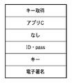
図23は例3で連携するアプリケーション内の一部のタスクのアイコン表示例を示している。例3で連携するアプリケーション内のタスクとしては、例えば、図27に示されるように、スキャンタスク、電子署名付与タスク、検証タスク、プリントタスク、キー取得タスク、ログインタスクがある。スキャンタスク231は紙文書のスキャンを実行するタスクである。電子署名付与タスクは、電子署名を付与する処理を実行するタスクである。検証タスクは、署名済みのデータの検証を行うタスクである。プリントタスクは、データをプリント処理するタスクである。キー取得タスクは電子署名を付与するためのキーを取得するタスクである。ログインタスク236はユーザ認証をするためのタスクである。各タスクの入出力データは図27に示す通りである。図23において、タスクアイコン231〜236はそれぞれスキャンタスク、電子署名付与タスク、検証タスク、プリントタスク、キー取得タスク、ログインタスクに対応する。
FIG. 23 shows an icon display example of some tasks in the application linked in Example 3. Examples of tasks in the application linked in Example 3 include a scan task, an electronic signature assignment task, a verification task, a print task, a key acquisition task, and a login task, as shown in FIG. The
図24は例3におけるアプリケーションのタスクであるキー取得タスク235のタスク定義情報を示している。図24はキー取得タスクがアプリC(例3で連携するアプリケーションに該当)の「電子署名」カテゴリに属していることを示している。また、入力データとしてIDデータとpassデータが必要であり、出力データとしてキーデータが出力されることが示されている。
FIG. 24 shows task definition information of a
図25は図24のタスク定義情報及び図23で示したタスクをもとにタスクをカテゴライズした例を図示している。例3では、各タスクはそれぞれ「電子署名」カテゴリ251と「デバイス」カテゴリ252と「ユーザ認証」カテゴリ253にカテゴライズされている。「電子署名」カテゴリ251には、電子署名付与タスク、検証タスク、キー取得タスク、ログインタスクが分類される。また、「デバイス」カテゴリ252にはスキャンタスク及びプリントタスクが分類され、「ユーザ認証」カテゴリ253にはログインタスクが分類されている。
FIG. 25 illustrates an example of categorizing tasks based on the task definition information in FIG. 24 and the tasks illustrated in FIG. In Example 3, each task is categorized into an “electronic signature”
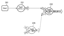
図26A〜図26Dは例3におけるジョブフローの作成手順を図示している。即ち、図22で示すアプリケーションを使用して、スキャンデータに電子署名を付与し、プリントするまでの流れをジョブフローとして定義する作成手順を表している。なお、図26A〜Dは、ジョブフロー作成エディタのジョブフロー作成ウィンドウ69(図6)上での操作例を示している。 26A to 26D illustrate a job flow creation procedure in the third example. That is, it shows a creation procedure for defining a flow from printing an electronic signature to scan data using the application shown in FIG. 22 and printing as a job flow. 26A to 26D show examples of operations on the job flow creation window 69 (FIG. 6) of the job flow creation editor.
図26Aでは、スタートアイコン261から開始し、スキャンタスク(タスクアイコン231)に続いて電子署名付与タスク(タスクアイコン263)までが配置されている。電子署名付与タスクにはPDFデータ及びキーデータの2つの入力データ必要であるのに対し、スキャンタスク231の出力データはPDFデータのみである。従って、電子署名付与タスク263まで配置した時点では入力データが不足しており、電子署名付与タスク263に続くタスクを配置することができない。そこで、例1、例2で説明したように、候補タスクの一覧を図26Bに示す如く表示する。即ち、入力データが不足しているタスクがジョブフロー作成ウィンドウ69上に配置された時点で、該タスクが入力として必要なデータを出力データにもつタスクで且つ、該タスクと同カテゴリに存在する候補タスクの一覧を表示(265)する。例3では、キーデータを出力データとし、「電子署名」カテゴリ251に属するキー取得タスク(タスクアイコン235)が候補として表示されることになる。キー取得タスクが選択されると、図26Cに示すようにキー取得タスクに対応するタスクアイコン235が確定される。
In FIG. 26A, starting from a
例3では、図26Bで候補として唯一表示したキー取得タスクは入力データを必要とするタスクである。そのため、該タスクが選択された時点で、該タスクを実行するために必要なタスクの候補が図26Bと同様の方法で表示される。例3では、ログインタスクに対応するタスクアイコン236がキー取得タスクと同カテゴリで且つその出力データの型がキー取得タスクの出力データの型と一致する。そのため、図26Cに示されるように、ログインタスクが候補タスクとして表示される。ログインタスク(タスクアイコン236)を選択することにより、電子署名付与タスク232のための並列処理が完成する。図26Dは並列処理の合流を含んだジョブフローを作成した結果を図示している。
In Example 3, the key acquisition task displayed as a candidate in FIG. 26B is a task that requires input data. For this reason, when the task is selected, candidate tasks necessary for executing the task are displayed in the same manner as in FIG. 26B. In Example 3, the
ジョブフロー作成者は、電子署名付与タスクを実行するために必要なタスクの配置が終了後、電子署名付与タスクに続くタスクとしてプリントタスクを配置し、更にEndアイコン267を配置してジョブフローの作成が終了する。なお、ログインタスクの実行開始地点はスタート地点に配置(268)される。
The job flow creator arranges a print task as a task subsequent to the electronic signature assignment task after arranging the tasks necessary for executing the electronic signature assignment task, and further arranges an
以上の図26A〜図26Dに示された操作に対応する処理を図12、図13のフローチャートを参照して説明する。 Processing corresponding to the operations shown in FIGS. 26A to 26D will be described with reference to the flowcharts of FIGS.
ジョブフローエディタが起動され図12の処理が開始される。まず、スキャンタスク(タスクアイコン231)が配置されると、ステップS2において、配置されたスキャンタスクの入力データが不足しているかどうかをチェックする。スキャンタスクの入力データは「ない」ので、入力データの不足はなく、次のタスクの配置へ進むべく、ステップS1へ処理を戻す。次に、電子署名付与タスク8タスクアイコン232)が配置されると、スキャンタスクと同様、ステップS2で電子署名付与タスクの入力データが不足しているかどうかチェックされる。電子署名付与タスクは、入力データにPDFデータ及びキーデータを必要とするが、これに接続されているスキャンタスクは出力データとしてPDFデータを有するのみである。従って、スキャンタスクでは入力データが不足しており、処理はステップS2からステップS3へ進む。 The job flow editor is activated and the processing in FIG. 12 is started. First, when a scan task (task icon 231) is arranged, it is checked in step S2 whether input data of the arranged scan task is insufficient. Since there is no input data for the scan task, there is no shortage of input data, and the process returns to step S1 to proceed to the next task arrangement. Next, when the electronic signature assignment task 8 task icon 232) is arranged, it is checked whether or not the input data of the electronic signature assignment task is insufficient in step S2, as in the scan task. The electronic signature assignment task requires PDF data and key data as input data, but the scan task connected thereto only has PDF data as output data. Accordingly, the scan task has insufficient input data, and the process proceeds from step S2 to step S3.
ステップS3では、「タスク検索&表示&選択」処理が実行される。即ち、当該タスクの属するカテゴリに属するタスクから候補タスクの対象とする。即ち、ステップS103〜S106において、電子署名付与タスクと同カテゴリ(電子署名カテゴリ251)に属するタスクで、キーデータを出力データとするタスクが抽出される。ここではキー取得タスクが抽出され、ステップS107において、候補タスクとして図26Bに示す如く表示される。 In step S3, a “task search & display & selection” process is executed. In other words, a task belonging to the category to which the task belongs is selected as a candidate task. That is, in steps S103 to S106, a task belonging to the same category (electronic signature category 251) as the electronic signature assignment task is extracted with the key data as output data. Here, the key acquisition task is extracted, and is displayed as a candidate task as shown in FIG. 26B in step S107.
このキー取得タスクが選択されると、当該タスクは入力データが必要かどうかが判定される(ステップS109)。キー取得タスクは、IDデータとpassデータを必要とするため、ステップS110へ進み、キー取得タスクを対象として「タスク検索&表示&選択」処理が再帰的に実行される。 When this key acquisition task is selected, it is determined whether the task requires input data (step S109). Since the key acquisition task requires ID data and pass data, the process proceeds to step S110, and the “task search & display & selection” process is recursively executed for the key acquisition task.
この結果、キー取得タスクと同じカテゴリに属し、IDデータとpassデータを出力データとして持つログインタスクが候補タスクとして表示される(ステップS107)。ログインタスクが選択されると、ログインタスクは入力データを必要としないので、キー取得タスクを対象とした「タスク検索&表示&選択」を終了する。そして、電子署名付与タスクを対象とした「タスク検索&表示&選択」が終了し、処理はステップS1へ戻る。 As a result, a login task that belongs to the same category as the key acquisition task and has ID data and pass data as output data is displayed as a candidate task (step S107). When the login task is selected, the login task does not require input data, and thus “task search & display & selection” for the key acquisition task is terminated. Then, “task search & display & selection” for the electronic signature assignment task ends, and the process returns to step S1.
その後、プリントタスクが配置されると、ステップS1からステップS2へ進み、配置されたスキャンタスクの入力データが不足しているかどうかをチェックする。例3では、プリントタスクの入力データは1つであり、入力データの不足はないので処理をステップS1に戻す。その後、Endアイコン267が配置されると、本ジョブフロー作成処理が終了する。
Thereafter, when the print task is arranged, the process proceeds from step S1 to step S2, and it is checked whether or not the input data of the arranged scan task is insufficient. In Example 3, since there is only one input data for the print task and there is no shortage of input data, the process returns to step S1. Thereafter, when the
なお、上記の図13に示したステップS104とS105の処理に関して、図11B、図20B、図26Bでは、入力データの不足が1つの場合を示している。図26Cでは、キー取得タスクが2つの入力データを必要としており、2つの入力データが不足している場合が示されている。図26Cの例では、ステップS104、S105において、電子署名カテゴリに属し、2つの入力データを出力データとして有するタスク(ログインタスク)が候補タスクとして提示されている。 Regarding the processing of steps S104 and S105 shown in FIG. 13 above, FIGS. 11B, 20B, and 26B show a case where there is one shortage of input data. FIG. 26C shows a case where the key acquisition task requires two input data and the two input data are insufficient. In the example of FIG. 26C, in steps S104 and S105, a task (login task) belonging to the electronic signature category and having two input data as output data is presented as a candidate task.
しかしながら、複数の入力データが不足した場合に、不足した複数の入力データの一部を含むタスクを候補タスクとして提示するようにしてもよい。図26Cのキー取得タスクの場合、電子署名カテゴリに属し、出力データとしてIDデータまたはpassデータを含むタスクを候補タスクとして提示するようにしてもよい。 However, when a plurality of input data is insufficient, a task including a part of the plurality of input data that is insufficient may be presented as a candidate task. In the case of the key acquisition task in FIG. 26C, a task that belongs to the electronic signature category and includes ID data or pass data as output data may be presented as a candidate task.
また、例えば、入力データA,B,Cが不足している場合に以下の(1)〜(5)の順に候補タスクを提示するようにしてもよい。なお、(1)〜(5)の候補タスクの提示は、所定のユーザ操作により切り替えるようにする。
(1)A,B,Cを出力データとして有するタスクを候補タスクとする。
(2)A,Bを出力データとして有するタスクとCを出力データとして有するタスクを候補タスクとする。
(3)A,Cを出力データとして有するタスクとBを出力データとして有するタスクを候補タスクとする。
(4)B,Cを出力データとして有するタスクとAを出力データとして有するタスクを候補タスクとする。
(5)Aを出力データとして有するタスクとBを出力データとして有するタスクとCを出力データとして有するタスクを候補タスクとする。
For example, when input data A, B, and C are insufficient, candidate tasks may be presented in the following order (1) to (5). The presentation of candidate tasks (1) to (5) is switched by a predetermined user operation.
(1) A task having A, B, and C as output data is set as a candidate task.
(2) A task having A and B as output data and a task having C as output data are set as candidate tasks.
(3) A task having A and C as output data and a task having B as output data are set as candidate tasks.
(4) A task having B and C as output data and a task having A as output data are set as candidate tasks.
(5) A task having A as output data, a task having B as output data, and a task having C as output data are set as candidate tasks.
以上のような実施形態のタスク連携システムによれば、複雑な処理を含むジョブフロー作成時に以下の効果を得ることができる。すなわち、
・入力データの不足を補うための接続可能な候補タスクが表示されるので、複雑な並列処理やタスク間の接続性を意識することなく簡単に目的のジョブフローを作成することができる。
・複数の入力データを必要とするタスクであっても、入力データが1つの場合のタスクと変わらずに容易にジョブフローを作成することができる。
According to the task cooperation system of the embodiment as described above, the following effects can be obtained when creating a job flow including complicated processing. That is,
・ Connectable candidate tasks are displayed to make up for the shortage of input data, so the target job flow can be easily created without being aware of complex parallel processing and connectivity between tasks.
Even if a task requires a plurality of input data, a job flow can be easily created without changing from a task with a single input data.
アプリケーションにおけるタスクでは、複数の入力を必要とするタスクが数多く存在することが予想される。そのような場合、アプリケーションを十分理解したユーザでなければ、タスク間の接続性を意識して複雑な並列処理を含んだジョブフローを作成することは困難である。上記実施形態のタスク連携システムによれば、接続可能な候補タスクの提示により並列処理を含んだジョブフローを容易に定義することができる。よって、上記実施形態におけるジョブフロー作成方法を使用することは大変意義のあることである。 It is expected that there are many tasks that require a plurality of inputs as tasks in the application. In such a case, it is difficult for a user who does not understand the application to create a job flow including complex parallel processing in consideration of connectivity between tasks. According to the task cooperation system of the above embodiment, a job flow including parallel processing can be easily defined by presenting connectable candidate tasks. Therefore, it is very meaningful to use the job flow creation method in the above embodiment.
<他の実施形態>
以上、実施形態を詳述したが、本発明は、例えば、システム、装置、方法、プログラムもしくは記憶媒体等としての実施態様をとることが可能である。具体的には、複数の機器から構成されるシステムに適用しても良いし、また、一つの機器からなる装置に適用しても良い。
<Other embodiments>
Although the embodiment has been described in detail above, the present invention can take an embodiment as a system, apparatus, method, program, storage medium, or the like. Specifically, the present invention may be applied to a system composed of a plurality of devices, or may be applied to an apparatus composed of a single device.
また、前述の実施形態では、文書データのコピー、スキャン、Fax送信、印刷処理装置内のハードディスクへの保存、メール送信等の印刷処理装置のタスクと外部連携するパーソナルコンピュータ等の情報処理装置上で動作するアプリケーションを例に挙げた。つまり印刷処理装置のタスクと情報処理装置上で動作するアプリケーションの処理タスクが連携してジョブフローを形成する例である。しかしながら本発明は印刷処理装置と情報処理装置の連携を必須とするものではなく、印刷処理装置単体内でのジョブフローの生成に適用して良い。また、情報処理装置単体あるいは複数の情報処理装置上で動作するアプリケーションの処理タスクが連携してジョブフローを形成する場合に適用しても良い。 In the above-described embodiment, the document data is copied, scanned, faxed, stored in the hard disk in the print processing apparatus, or sent on the information processing apparatus such as a personal computer externally linked with the print processing apparatus tasks such as mail transmission. An example of a running application was given. In other words, this is an example in which a task of the print processing apparatus and a processing task of an application operating on the information processing apparatus cooperate to form a job flow. However, the present invention does not necessarily require cooperation between the print processing apparatus and the information processing apparatus, and may be applied to generation of a job flow within the single print processing apparatus. Further, the present invention may be applied to a case where processing tasks of applications operating on a single information processing apparatus or a plurality of information processing apparatuses cooperate to form a job flow.
尚、本発明は、ソフトウェアのプログラムをシステム或いは装置に直接或いは遠隔から供給し、そのシステム或いは装置のコンピュータが該供給されたプログラムコードを読み出して実行することによって前述した実施形態の機能が達成される場合を含む。この場合、供給されるプログラムは実施形態で図に示したフローチャートに対応したプログラムである。 In the present invention, the functions of the above-described embodiments are achieved by supplying a software program directly or remotely to a system or apparatus, and the computer of the system or apparatus reads and executes the supplied program code. Including the case. In this case, the supplied program is a program corresponding to the flowchart shown in the drawing in the embodiment.
従って、本発明の機能処理をコンピュータで実現するために、該コンピュータにインストールされるプログラムコード自体も本発明を実現するものである。つまり、本発明は、本発明の機能処理を実現するためのコンピュータプログラム自体も含まれる。
その場合、プログラムの機能を有していれば、オブジェクトコード、インタプリタにより実行されるプログラム、OSに供給するスクリプトデータ等の形態であっても良い。
Accordingly, since the functions of the present invention are implemented by computer, the program code installed in the computer also implements the present invention. In other words, the present invention includes a computer program itself for realizing the functional processing of the present invention.
In that case, as long as it has the function of a program, it may be in the form of object code, a program executed by an interpreter, script data supplied to the OS, or the like.
プログラムを供給するための記録媒体としては以下が挙げられる。例えば、フロッピー(登録商標)ディスク、ハードディスク、光ディスク、光磁気ディスク、MO、CD−ROM、CD−R、CD−RW、磁気テープ、不揮発性のメモリカード、ROM、DVD(DVD−ROM,DVD−R)などである。 Examples of the recording medium for supplying the program include the following. For example, floppy (registered trademark) disk, hard disk, optical disk, magneto-optical disk, MO, CD-ROM, CD-R, CD-RW, magnetic tape, nonvolatile memory card, ROM, DVD (DVD-ROM, DVD- R).
その他、プログラムの供給方法としては、クライアントコンピュータのブラウザを用いてインターネットのホームページに接続し、該ホームページから本発明のコンピュータプログラムをハードディスク等の記録媒体にダウンロードすることが挙げられる。この場合、ダウンロードされるプログラムは、圧縮され自動インストール機能を含むファイルであってもよい。また、本発明のプログラムを構成するプログラムコードを複数のファイルに分割し、それぞれのファイルを異なるホームページからダウンロードすることによっても実現可能である。つまり、本発明の機能処理をコンピュータで実現するためのプログラムファイルを複数のユーザに対してダウンロードさせるWWWサーバも、本発明に含まれるものである。 As another program supply method, a client computer browser is used to connect to a homepage on the Internet, and the computer program of the present invention is downloaded from the homepage to a recording medium such as a hard disk. In this case, the downloaded program may be a compressed file including an automatic installation function. It can also be realized by dividing the program code constituting the program of the present invention into a plurality of files and downloading each file from a different homepage. That is, a WWW server that allows a plurality of users to download a program file for realizing the functional processing of the present invention on a computer is also included in the present invention.
また、本発明のプログラムを暗号化してCD−ROM等の記憶媒体に格納してユーザに配布するという形態をとることもできる。この場合、所定の条件をクリアしたユーザに、インターネットを介してホームページから暗号を解く鍵情報をダウンロードさせ、その鍵情報を使用して暗号化されたプログラムを実行し、プログラムをコンピュータにインストールさせるようにもできる。 Further, the program of the present invention may be encrypted, stored in a storage medium such as a CD-ROM, and distributed to users. In this case, a user who has cleared a predetermined condition is allowed to download key information for decryption from a homepage via the Internet, execute an encrypted program using the key information, and install the program on the computer. You can also.
また、コンピュータが、読み出したプログラムを実行することによって、前述した実施形態の機能が実現される他、そのプログラムの指示に基づき、コンピュータ上で稼動しているOSなどとの協働で実施形態の機能が実現されてもよい。この場合、OSなどが、実際の処理の一部または全部を行ない、その処理によって前述した実施形態の機能が実現される。 In addition to the functions of the above-described embodiment being realized by the computer executing the read program, the embodiment of the embodiment is implemented in cooperation with an OS or the like running on the computer based on an instruction of the program. A function may be realized. In this case, the OS or the like performs part or all of the actual processing, and the functions of the above-described embodiments are realized by the processing.
さらに、記録媒体から読み出されたプログラムが、コンピュータに挿入された機能拡張ボードやコンピュータに接続された機能拡張ユニットに備わるメモリに書き込まれて前述の実施形態の機能の一部或いは全てが実現されてもよい。この場合、機能拡張ボードや機能拡張ユニットにプログラムが書き込まれた後、そのプログラムの指示に基づき、その機能拡張ボードや機能拡張ユニットに備わるCPUなどが実際の処理の一部または全部を行なう。 Furthermore, the program read from the recording medium is written in a memory provided in a function expansion board inserted into the computer or a function expansion unit connected to the computer, so that part or all of the functions of the above-described embodiments are realized. May be. In this case, after a program is written in the function expansion board or function expansion unit, the CPU or the like provided in the function expansion board or function expansion unit performs part or all of the actual processing based on the instructions of the program.
Claims (14)
フローを生成するために、第1の処理に後続する処理として第2の処理の接続が画面上で指示された場合、複数の処理の各々について入力データと出力データを規定するとともに各処理が属するカテゴリを示す処理情報が登録された登録手段に登録されている前記第1及び第2の処理の処理情報を参照することにより、前記第2の処理の入力データが不足するか否かを判定し、
不足すると判定された場合、前記第2の処理と同じカテゴリに属するとともに、不足している入力データを出力可能な処理を、前記登録手段に登録されている処理情報を参照して、前記登録手段に登録されている前記複数の処理の中から候補処理として取得し、
取得した候補処理を画面上に提示し、
提示した候補処理のうちの一つを選択する操作に応じて、選択された候補処理を前記第2の処理の前段の処理として接続して画面上に表示することを特徴とする情報処理装置。 An information processing apparatus for generating a flow in which a plurality of processes are connected on a screen ,
In order to generate a flow, when connection of the second process is instructed on the screen as a process subsequent to the first process, input data and output data are defined for each of the plurality of processes, and each process belongs by referring to the processing information of the first and second processing process information indicating a category is registered in the registration means is registered, it determines whether the input data of the second process is insufficient ,
If it is determined that there is a shortage, a process that belongs to the same category as the second process and that can output the missing input data is referred to the process information registered in the registration means, and the registration means Obtained as a candidate process from the plurality of processes registered in
The acquired candidate process presented on the screen,
In accordance with an operation of selecting one of the presented candidate processes, the selected candidate process is connected as a process preceding the second process and displayed on the screen. .
フローを生成するために、第1の処理に後続する処理として第2の処理の接続が画面上で指示された場合、複数の処理の各々について入力データと出力データを規定するとともに各処理が属するカテゴリを示す処理情報とカテゴリの階層構造を示す階層情報とが登録された登録手段に登録されている前記第1及び第2の処理の処理情報を参照することにより、前記第2の処理の入力データが不足するか否かを判定し、
不足すると判定された場合、前記第2の処理と同じカテゴリまたは該カテゴリの上位階層のカテゴリに属し、不足している入力データを出力可能な処理を、前記登録手段に登録されている処理情報と階層情報を参照して、前記登録手段に登録されている前記複数の処理の中から候補処理として取得し、
取得された候補処理を画面上に提示し、
提示した候補処理のうちの一つを選択する操作に応じて、選択された候補処理を前記第2の処理の前段の処理として接続して画面上に表示することを特徴とする情報処理装置。 An information processing apparatus for generating a flow in which a plurality of processes are connected on a screen ,
In order to generate a flow, when connection of the second process is instructed on the screen as a process subsequent to the first process, input data and output data are defined for each of the plurality of processes, and each process belongs The input of the second process by referring to the process information of the first and second processes registered in the registration means in which the process information indicating the category and the hierarchy information indicating the hierarchical structure of the category are registered. it is determined whether or not the data is insufficient,
If it is determined that there is a shortage, a process that belongs to the same category as the second process or a category in a higher hierarchy of the category and that can output the deficient input data is processed information registered in the registration unit. Referring to the hierarchy information, obtaining as a candidate process from the plurality of processes registered in the registration means,
The obtained candidate process provides suggestions on a screen,
In accordance with an operation of selecting one of the presented candidate processes, the selected candidate process is connected as a process preceding the second process and displayed on the screen. .
前記選択された処理と同じカテゴリに属するとともに、不足している入力データを出力可能な処理を、前記登録手段に登録されている処理情報を参照して、前記登録手段に登録されている前記複数の処理の中から候補処理として取得し、
取得した候補処理を画面上に提示し、
提示した候補処理のうちの一つを選択する操作に応じて、選択された候補処理を前記選択された処理の前段の処理として接続して画面上に表示する、ことを特徴とする請求項1乃至5のいずれか1項に記載の情報処理装置。 The information processing apparatus, when a process selected from the candidate process presented on the screen requires input data, it is determined that the input data of the selected process is insufficient,
The plurality of processes registered in the registration unit with reference to the process information registered in the registration unit for processes that belong to the same category as the selected process and that can output missing input data Is obtained as a candidate process from
Present the acquired candidate process on the screen,
2. The selected candidate process is connected as a process preceding the selected process and displayed on the screen in response to an operation of selecting one of the presented candidate processes. The information processing apparatus according to any one of 1 to 5.
フローを生成するために、第1の処理に後続する処理として第2の処理の接続が指示された場合、前記情報処理装置のコンピュータが、複数の処理の各々について入力データと出力データを規定するとともに各処理が属するカテゴリを示す処理情報が登録された登録手段に登録されている前記第1及び第2の処理の処理情報を参照することにより、前記第2の処理の入力データが不足するか否かを判定する判定工程と、
前記判定工程で不足すると判定された場合、前記情報処理装置のコンピュータが、前記第2の処理と同じカテゴリに属するとともに、不足している入力データを出力可能な処理を、前記登録手段に登録されている処理情報を参照して、前記登録手段に登録されている前記複数の処理の中から候補処理として取得する取得工程と、
前記情報処理装置のコンピュータが、前記取得工程で取得した候補処理を表示装置に表示させる提示工程と、
前記情報処理装置のコンピュータが、前記提示工程で提示された候補処理のうちの一つを選択する操作に応じて、選択された候補処理を前記第2の処理の前段の処理として接続する接続工程とを備えることを特徴とする情報処理方法。 An information processing method by an information processing apparatus that generates a flow in which a plurality of processes are connected,
In order to generate a flow, when connection of the second process is instructed as a process subsequent to the first process, the computer of the information processing apparatus defines input data and output data for each of the plurality of processes. Whether the input data of the second process is insufficient by referring to the process information of the first and second processes registered in the registration means in which the process information indicating the category to which each process belongs is registered A determination step of determining whether or not,
If it is determined in the determination step that the information processing apparatus is insufficient, the computer of the information processing apparatus belongs to the same category as the second process, and a process capable of outputting the insufficient input data is registered in the registration unit. An acquisition step of acquiring as a candidate process from among the plurality of processes registered in the registration means;
A presentation step in which the computer of the information processing device displays the candidate process acquired in the acquisition step on a display device;
A connection step in which the computer of the information processing apparatus connects the selected candidate process as a process preceding the second process in response to an operation of selecting one of the candidate processes presented in the presenting step. An information processing method comprising:
フローを生成するために、第1の処理に後続する処理として第2の処理の接続が指示された場合、前記情報処理装置のコンピュータが、複数の処理の各々について入力データと出力データを規定するとともに各処理が属するカテゴリを示す処理情報とカテゴリの階層構造を示す階層情報とが登録された登録手段に登録されている前記第1及び第2の処理の処理情報を参照することにより、前記第2の処理の入力データが不足するか否かを判定する判定工程と、
前記判定工程で不足すると判定された場合、前記情報処理装置のコンピュータが、前記第2の処理と同じカテゴリまたは該カテゴリの上位階層のカテゴリに属し、不足している入力データを出力可能な処理を、前記登録手段に登録されている処理情報と階層情報を参照して、前記登録手段に登録されている前記複数の処理の中から候補処理として取得する取得工程と、
前記情報処理装置のコンピュータが、前記取得工程で取得した候補処理を表示装置に表示させる提示工程と、
前記情報処理装置のコンピュータが、前記提示工程で提示された候補処理のうちの一つを選択する操作に応じて、選択された候補処理を前記第2の処理の前段の処理として接続する接続工程とを備えることを特徴とする情報処理方法。 An information processing method by an information processing apparatus that generates a flow in which a plurality of processes are connected,
In order to generate a flow, when connection of the second process is instructed as a process subsequent to the first process, the computer of the information processing apparatus defines input data and output data for each of the plurality of processes. And by referring to the processing information of the first and second processes registered in the registration means in which the processing information indicating the category to which each process belongs and the hierarchical information indicating the hierarchical structure of the category are registered. A determination step of determining whether or not the input data of the process 2 is insufficient;
When it is determined in the determination step that the information processing apparatus is insufficient, the computer of the information processing apparatus belongs to the same category as the second process or a category in an upper hierarchy of the category, and is capable of outputting the input data that is insufficient Obtaining the candidate process from among the plurality of processes registered in the registration unit with reference to the process information and hierarchy information registered in the registration unit;
A presentation step in which the computer of the information processing device displays the candidate process acquired in the acquisition step on a display device;
A connection step in which the computer of the information processing apparatus connects the selected candidate process as a process preceding the second process in response to an operation of selecting one of the candidate processes presented in the presenting step. An information processing method comprising:
前記選択された処理と同じカテゴリに属するとともに、不足している入力データを出力可能な処理を、前記登録手段に登録されている処理情報を参照して、前記登録手段に登録されている前記複数の処理の中から候補処理として取得し、
取得した候補処理を画面上に提示し、
提示した候補処理のうちの一つを選択する操作に応じて、選択された候補処理を前記選択された処理の前段の処理として接続して画面上に表示する、ことを特徴とする請求項7乃至11のいずれか1項に記載の情報処理方法。 The computer of the information processing apparatus, when a process selected from the candidate process presented in said presenting step requires the input data, it is determined as the input data of the selected process is insufficient ,
The plurality of processes registered in the registration unit with reference to the process information registered in the registration unit for processes that belong to the same category as the selected process and that can output missing input data Is obtained as a candidate process from
Present the acquired candidate process on the screen,
8. The selected candidate process is connected as a process preceding the selected process and displayed on the screen according to an operation of selecting one of the presented candidate processes. The information processing method of any one of thru | or 11.
フローを生成するために、第1の処理に後続する処理として第2の処理の接続が指示された場合、複数の処理の各々について入力データと出力データを規定するとともに各処理が属するカテゴリを示す処理情報が登録された登録手段に登録されている前記第1及び第2の処理の処理情報を参照することにより、前記第2の処理の入力データが不足するか否かを判定する判定工程と、
前記判定工程で不足すると判定された場合、前記第2の処理と同じカテゴリに属するとともに、不足している入力データを出力可能な処理を、前記登録手段に登録されている処理情報を参照して、前記登録手段に登録されている前記複数の処理の中から候補処理として取得する取得工程と、
前記取得工程で取得した候補処理を表示装置に表示させる提示工程と、
前記提示工程で提示された候補処理のうちの一つを選択する操作に応じて、選択された候補処理を前記第2の処理の前段の処理として接続する接続工程と、を実行させるためのプログラム。 A program for causing a computer to execute information processing for generating a flow in which a plurality of processes are connected,
In order to generate a flow, when the connection of the second process is instructed as a process subsequent to the first process, the input data and the output data are defined for each of the plurality of processes and the category to which each process belongs is indicated. A determination step of determining whether or not input data of the second process is insufficient by referring to the process information of the first and second processes registered in the registration unit in which the process information is registered; ,
If it is determined in the determination step that there is a shortage, a process that belongs to the same category as the second process and that can output the input data that is insufficient is referred to the processing information registered in the registration unit. An acquisition step of acquiring as a candidate process from the plurality of processes registered in the registration means;
A presentation step for displaying the candidate process acquired in the acquisition step on a display device;
A program for executing a connection step of connecting the selected candidate process as a process preceding the second process in response to an operation of selecting one of the candidate processes presented in the presenting step .
フローを生成するために、第1の処理に後続する処理として第2の処理の接続が指示された場合、複数の処理の各々について入力データと出力データを規定するとともに各処理が属するカテゴリを示す処理情報とカテゴリの階層構造を示す階層情報とが登録された登録手段に登録されている前記第1及び第2の処理の処理情報を参照することにより、前記第2の処理の入力データが不足するか否かを判定する判定工程と、
前記判定工程で不足すると判定された場合、前記第2の処理と同じカテゴリまたは該カテゴリの上位階層のカテゴリに属し、不足している入力データを出力可能な処理を、前記登録手段に登録されている処理情報と階層情報を参照して、前記登録手段に登録されている前記複数の処理の中から候補処理として取得する取得工程と、
前記取得工程で取得した候補処理を表示装置に表示させる提示工程と、
前記提示工程で提示された候補処理のうちの一つを選択する操作に応じて、選択された候補処理を前記第2の処理の前段の処理として接続する接続工程と、をコンピュータに実行させるためのプログラム。 A program for causing a computer to execute information processing for generating a flow in which a plurality of processes are connected,
In order to generate a flow, when the connection of the second process is instructed as a process subsequent to the first process, the input data and the output data are defined for each of the plurality of processes and the category to which each process belongs is indicated. Input data of the second process is insufficient by referring to the process information of the first and second processes registered in the registration means in which the process information and the hierarchical information indicating the hierarchical structure of the category are registered A determination step of determining whether or not to do;
If it is determined in the determination step that there is a shortage, a process that belongs to the same category as the second process or a higher-level category of the category and that can output the input data that is insufficient is registered in the registration unit. An acquisition step of acquiring as candidate processes from among the plurality of processes registered in the registration means, with reference to the process information and hierarchy information being
A presentation step for displaying the candidate process acquired in the acquisition step on a display device;
In order to cause the computer to execute a connection step of connecting the selected candidate process as a preceding process of the second process in response to an operation of selecting one of the candidate processes presented in the presenting step Program.
Priority Applications (2)
| Application Number | Priority Date | Filing Date | Title |
|---|---|---|---|
| JP2005228474A JP4756947B2 (en) | 2005-08-05 | 2005-08-05 | Information processing apparatus and method |
| US11/462,431 US20070044009A1 (en) | 2005-08-05 | 2006-08-04 | Information processing apparatus and method |
Applications Claiming Priority (1)
| Application Number | Priority Date | Filing Date | Title |
|---|---|---|---|
| JP2005228474A JP4756947B2 (en) | 2005-08-05 | 2005-08-05 | Information processing apparatus and method |
Publications (3)
| Publication Number | Publication Date |
|---|---|
| JP2007047862A JP2007047862A (en) | 2007-02-22 |
| JP2007047862A5 JP2007047862A5 (en) | 2007-09-20 |
| JP4756947B2 true JP4756947B2 (en) | 2011-08-24 |
Family
ID=37768544
Family Applications (1)
| Application Number | Title | Priority Date | Filing Date |
|---|---|---|---|
| JP2005228474A Expired - Fee Related JP4756947B2 (en) | 2005-08-05 | 2005-08-05 | Information processing apparatus and method |
Country Status (2)
| Country | Link |
|---|---|
| US (1) | US20070044009A1 (en) |
| JP (1) | JP4756947B2 (en) |
Families Citing this family (18)
| Publication number | Priority date | Publication date | Assignee | Title |
|---|---|---|---|---|
| JP5142481B2 (en) * | 2005-10-13 | 2013-02-13 | キヤノン株式会社 | Information processing apparatus, task linkage processing system, task linkage flow creation method, service processing method, management server, flow conversion method, flow execution method, and program |
| JP4847260B2 (en) * | 2006-09-19 | 2011-12-28 | キヤノン株式会社 | Data processing apparatus, data processing method, and computer program |
| US10997531B2 (en) * | 2007-09-11 | 2021-05-04 | Ciambella Ltd. | System, method and graphical user interface for workflow generation, deployment and/or execution |
| US20090070121A1 (en) * | 2007-09-11 | 2009-03-12 | Jean-Baptiste Leonelli | System, Method And Graphical User Interface For Workflow Generation, Deployment And/Or Execution |
| US8108831B2 (en) * | 2008-02-07 | 2012-01-31 | Microsoft Corporation | Iterative component binding |
| JP5426938B2 (en) * | 2009-06-23 | 2014-02-26 | キヤノン株式会社 | Information processing apparatus and information processing method |
| JP5499979B2 (en) * | 2010-07-30 | 2014-05-21 | 株式会社リコー | Image forming apparatus, image forming apparatus cooperation scenario creating method, program, and computer-readable recording medium |
| JP5595252B2 (en) * | 2010-12-14 | 2014-09-24 | 株式会社Nttドコモ | Cooperation support apparatus, program, cooperation support method, cooperation support system, and communication apparatus |
| US9311061B2 (en) * | 2011-02-10 | 2016-04-12 | International Business Machines Corporation | Designing task execution order based on location of the task icons within a graphical user interface |
| WO2013179469A1 (en) * | 2012-05-31 | 2013-12-05 | 富士通株式会社 | Operation process creation program, operation process creation method, and information-processing device |
| WO2013179468A1 (en) * | 2012-05-31 | 2013-12-05 | 富士通株式会社 | Operation process creation program, operation process creation method, and information-processing device |
| JP5942614B2 (en) * | 2012-06-05 | 2016-06-29 | 株式会社リコー | Information processing apparatus, system, and program |
| US9740538B1 (en) * | 2013-08-27 | 2017-08-22 | Ca, Inc. | Mapping data-flows in a workflow |
| JP6287396B2 (en) * | 2014-03-17 | 2018-03-07 | カシオ計算機株式会社 | Information processing apparatus and program |
| JP6400248B1 (en) * | 2017-03-03 | 2018-10-03 | 三菱電機株式会社 | Data processing apparatus, data processing method, setting management apparatus, and data processing system |
| JP6483757B2 (en) * | 2017-06-09 | 2019-03-13 | 株式会社東芝 | Job execution control device, job execution control method, and program |
| JP6822368B2 (en) * | 2017-09-29 | 2021-01-27 | ブラザー工業株式会社 | Computer program and workflow generator |
| JP7331402B2 (en) * | 2019-03-22 | 2023-08-23 | 富士フイルムビジネスイノベーション株式会社 | Flow generation device and flow generation program |
Family Cites Families (10)
| Publication number | Priority date | Publication date | Assignee | Title |
|---|---|---|---|---|
| JP2699381B2 (en) * | 1987-04-28 | 1998-01-19 | 富士ゼロックス株式会社 | Manufacturing method of resistor |
| US5386568A (en) * | 1992-12-01 | 1995-01-31 | Yamaha Corporation | Apparatus and method for linking software modules |
| JP2000089944A (en) * | 1998-07-15 | 2000-03-31 | Hitachi Software Eng Co Ltd | Method for displaying connection guide marker, system therefor and recording medium |
| JP2001216142A (en) * | 2000-02-04 | 2001-08-10 | Hitachi Ltd | Program preparation aiding device |
| JP2003044637A (en) * | 2001-08-01 | 2003-02-14 | Hitachi Ltd | Workflow system control method and program for executing the workflow system |
| JP3805298B2 (en) * | 2002-11-15 | 2006-08-02 | 株式会社半導体理工学研究センター | Integrated circuit testability design method and apparatus |
| US8561069B2 (en) * | 2002-12-19 | 2013-10-15 | Fujitsu Limited | Task computing |
| JP2004280714A (en) * | 2003-03-18 | 2004-10-07 | Hitachi Ltd | Design support management method, design support management system, and program for design support management |
| JP4218384B2 (en) * | 2003-03-24 | 2009-02-04 | 富士ゼロックス株式会社 | Service processing apparatus, service processing method and program, and image forming apparatus |
| EP1759289A4 (en) * | 2004-04-28 | 2008-08-20 | Fujitsu Ltd | Semantic task computing |
-
2005
- 2005-08-05 JP JP2005228474A patent/JP4756947B2/en not_active Expired - Fee Related
-
2006
- 2006-08-04 US US11/462,431 patent/US20070044009A1/en not_active Abandoned
Also Published As
| Publication number | Publication date |
|---|---|
| JP2007047862A (en) | 2007-02-22 |
| US20070044009A1 (en) | 2007-02-22 |
Similar Documents
| Publication | Publication Date | Title |
|---|---|---|
| JP4756947B2 (en) | Information processing apparatus and method | |
| JP4251645B2 (en) | Information processing method and apparatus | |
| US8373878B2 (en) | Cooperative job flow creating apparatus, cooperative job flow creating method, service processing apparatus, service processing method, management server, flow conversion method, job flow execution method, program, and storage medium | |
| JP5388541B2 (en) | Image processing apparatus, image processing system, control method thereof, program, and storage medium | |
| JP5199761B2 (en) | Information processing apparatus, image input apparatus, document distribution system, and control method therefor | |
| JP5276328B2 (en) | Information processing apparatus, control method thereof, and program | |
| JP5414242B2 (en) | Image processing apparatus, image processing apparatus control method, and program | |
| US9471328B2 (en) | Information processor having program and configuration data stored in different storage areas and reflecting configuration data in operation in program | |
| JP2010123124A (en) | Work flow management apparatus, and method and program of the same | |
| JP2008209985A (en) | Data processor, electronic document registration method and computer program | |
| JP5132375B2 (en) | Document management system and method enabling document operation using shortcut template | |
| JP2010016778A (en) | Image forming apparatus, information processing method, and image forming system | |
| JP2011123607A (en) | Information processing apparatus, information processing method and program | |
| JP5167200B2 (en) | Print job extraction apparatus and print system | |
| JP2007053468A (en) | Documentation management system, time signature processing method, storage medium, program | |
| JP2010134879A (en) | Visual programming support device, visual programming support method of visual programming support device, program, and storage medium | |
| JP5417043B2 (en) | Image forming apparatus, image forming system, and image processing method | |
| JP4455640B2 (en) | Image forming apparatus, image forming apparatus control method, image forming system, program, and storage medium | |
| JP2004288055A (en) | Service processing system, service processing method and service processing program | |
| JP2006018492A (en) | System, method, and program for processing document | |
| JP4912288B2 (en) | Management apparatus and information processing method | |
| JP4850618B2 (en) | Document management apparatus, control method therefor, program, and storage medium | |
| JP6744553B2 (en) | Information processing apparatus, information processing system, control method thereof, and program | |
| JP2018005794A (en) | Information processing device, control method, and program | |
| JP2005190366A (en) | Service processor and system and input terminal |
Legal Events
| Date | Code | Title | Description |
|---|---|---|---|
| A521 | Request for written amendment filed |
Free format text: JAPANESE INTERMEDIATE CODE: A523 Effective date: 20070803 |
|
| A621 | Written request for application examination |
Free format text: JAPANESE INTERMEDIATE CODE: A621 Effective date: 20070803 |
|
| RD03 | Notification of appointment of power of attorney |
Free format text: JAPANESE INTERMEDIATE CODE: A7423 Effective date: 20070803 |
|
| A977 | Report on retrieval |
Free format text: JAPANESE INTERMEDIATE CODE: A971007 Effective date: 20100629 |
|
| A131 | Notification of reasons for refusal |
Free format text: JAPANESE INTERMEDIATE CODE: A131 Effective date: 20101029 |
|
| A521 | Request for written amendment filed |
Free format text: JAPANESE INTERMEDIATE CODE: A523 Effective date: 20101228 |
|
| A02 | Decision of refusal |
Free format text: JAPANESE INTERMEDIATE CODE: A02 Effective date: 20110128 |
|
| A521 | Request for written amendment filed |
Free format text: JAPANESE INTERMEDIATE CODE: A523 Effective date: 20110422 |
|
| A911 | Transfer to examiner for re-examination before appeal (zenchi) |
Free format text: JAPANESE INTERMEDIATE CODE: A911 Effective date: 20110502 |
|
| TRDD | Decision of grant or rejection written | ||
| A01 | Written decision to grant a patent or to grant a registration (utility model) |
Free format text: JAPANESE INTERMEDIATE CODE: A01 Effective date: 20110523 |
|
| A01 | Written decision to grant a patent or to grant a registration (utility model) |
Free format text: JAPANESE INTERMEDIATE CODE: A01 |
|
| A61 | First payment of annual fees (during grant procedure) |
Free format text: JAPANESE INTERMEDIATE CODE: A61 Effective date: 20110531 |
|
| R150 | Certificate of patent or registration of utility model |
Ref document number: 4756947 Country of ref document: JP Free format text: JAPANESE INTERMEDIATE CODE: R150 Free format text: JAPANESE INTERMEDIATE CODE: R150 |
|
| FPAY | Renewal fee payment (event date is renewal date of database) |
Free format text: PAYMENT UNTIL: 20140610 Year of fee payment: 3 |
|
| LAPS | Cancellation because of no payment of annual fees |