JP4455640B2 - Image forming apparatus, image forming apparatus control method, image forming system, program, and storage medium - Google Patents
Image forming apparatus, image forming apparatus control method, image forming system, program, and storage medium Download PDFInfo
- Publication number
- JP4455640B2 JP4455640B2 JP2007263802A JP2007263802A JP4455640B2 JP 4455640 B2 JP4455640 B2 JP 4455640B2 JP 2007263802 A JP2007263802 A JP 2007263802A JP 2007263802 A JP2007263802 A JP 2007263802A JP 4455640 B2 JP4455640 B2 JP 4455640B2
- Authority
- JP
- Japan
- Prior art keywords
- data
- information
- image forming
- layout
- information processing
- Prior art date
- Legal status (The legal status is an assumption and is not a legal conclusion. Google has not performed a legal analysis and makes no representation as to the accuracy of the status listed.)
- Expired - Fee Related
Links
Images


Landscapes
- Accessory Devices And Overall Control Thereof (AREA)
- Record Information Processing For Printing (AREA)
- Processing Or Creating Images (AREA)
- Facsimiles In General (AREA)
- Editing Of Facsimile Originals (AREA)
Description
本発明は、ユーザの用途に応じたユーザインタフェース(UI)画面を構築し、UIからの指定によりマルチファンクション機器(MFP)固有の機能やサーバアプリケーションの機能を利用して画像形成する技術に関するものである。 The present invention relates to a technique for constructing a user interface (UI) screen corresponding to a user's application and forming an image by using a function unique to a multifunction device (MFP) or a function of a server application according to designation from the UI. is there.
近年、マルチファンクション機器(MFP)(以下、単に「画像形成装置」ともいう)にJava(登録商標)環境に代表されるようなアプリケーション実行環境が提供されるようになってきている。Java(登録商標)環境上で動作するプログラムを開発すれば、MFPの機能を利用したアプリケーションが作成可能である。一般にこれらのアプリケーションは、画面構成やMFPが提供する機能が固定的なパッケージ・アプリケーションと呼ばれるものが大半である。 In recent years, an application execution environment represented by a Java (registered trademark) environment has been provided for a multifunction device (MFP) (hereinafter also simply referred to as an “image forming apparatus”). If a program that operates in the Java (registered trademark) environment is developed, an application using the function of the MFP can be created. In general, most of these applications are called package applications in which the screen configuration and functions provided by the MFP are fixed.
一方で、MFPと通信可能なサーバ上で動作するサーバアプリケーションとを連携させたソリューションをユーザ企業に提供する場合、固定の画面構成や機能を提供するパッケージ・アプリケーションではユーザの要求仕様を柔軟に満たすことは困難である。 On the other hand, when providing a solution that links a server application that runs on a server that can communicate with the MFP to a user company, the package application that provides a fixed screen configuration and functions flexibly meets the user's required specifications. It is difficult.
例えば、特許文献1に開示されている技術によれば、MFPのアプリケーションプログラムをサーバからダウンロードして実行する技術が公開されている。しかしながら、特許文献1の開示内容は、MFPのアプリケーション自体のカスタマイズについては言及されておらず、ユーザの要求に応じて個別のソリューションを提供することは困難である。
For example, according to the technique disclosed in
MFPとサーバ上のアプリケーションとを連携させたソリューションの事例としては、文書管理サーバやコンテンツサーバに保管してあるファイルをMFPがネットワークを介して取得して印刷するプル型印刷システムの事例がある。また、MFPでスキャンして生成したスキャン文書ファイルを文書管理サーバやコンテンツサーバに登録するシステムなどの事例がある。 As an example of a solution in which an MFP and an application on a server are linked, there is an example of a pull type printing system in which an MFP acquires and prints a file stored in a document management server or content server via a network. In addition, there is a case of a system that registers a scanned document file generated by scanning with an MFP in a document management server or a content server.
例えば、プル型印刷を適用したパンフレット印刷システムを想定した場合、異なる業種である電器販売店と旅行代理店とは、異なった仕様のパンフレット印刷が要求される。例えば、電器販売店の場合、デジタルカメラ等の商品ごとにパンフレットを印刷したいという要求仕様が想定され、旅行代理店の場合は旅行の目的地別にパンフレットを印刷したいという要求仕様が想定される。こういった場合、MFPのUIはユーザが直接に見たり、触れたりして、処理したい業務に合わせてMFPやサーバアプリケーションに指示をするものであり、固定の画面構成では、想定される幅広いユーザの要求仕様を満たすことは困難であった。 For example, assuming a pamphlet printing system to which pull-type printing is applied, pamphlet printing with different specifications is required for electrical appliance stores and travel agents that are different industries. For example, in the case of an electric appliance store, a required specification that a pamphlet is desired to be printed for each product such as a digital camera is assumed, and in the case of a travel agency, a required specification that a pamphlet is desired to be printed for each destination is assumed. In such a case, the user interface of the MFP is directly viewed or touched by the user to instruct the MFP or server application according to the business to be processed. It was difficult to meet the required specifications.
また、特許文献2には、プリンタとスキャナの対応関係を、転送パスプロトコルとしてサーバに登録しておき、これを複合機等にダウンロードして配布する技術が記載されている。そして、当該転送パスプロトコルを用いて、プリンタとスキャナとの組に対応する仮想コピーのアイコンを操作パネルに表示する技術が記載されている。
従来の技術では、入力機器と出力機器の組合わせを示すアイコンを指示することにより、複数の機器を連携させることにより、ひとつのサービスを実行させることはできた。しかしながら、上記の従来技術では、指定される機器の複数の機能を単純に順次実行させるだけであった。画像形成装置が通信する外部の機器の様々な機能を活用し、柔軟に画像形成装置の機能を変更又は拡張することはできなかった。 In the prior art, by instructing an icon indicating a combination of an input device and an output device, a single service can be executed by linking a plurality of devices. However, in the above prior art, a plurality of functions of a designated device are simply executed sequentially. It has been impossible to flexibly change or expand the functions of the image forming apparatus by utilizing various functions of external devices with which the image forming apparatus communicates.
また、従来は、挿し込みデータとテンプレートとの組合わせに応じて、その度にフォームのレイアウトの設計を行う必要があった。このため、画像形成装置におけるユーザからの簡単な指示だけでは所望の出力物を得ることができなかった。 Conventionally, it has been necessary to design a form layout each time a combination of insertion data and a template is used. For this reason, a desired output cannot be obtained only by a simple instruction from the user in the image forming apparatus.
本発明のひとつの側面は、画像形成装置が通信する外部の情報処理装置の様々な機能を活用して、画像形成装置の機能を拡張又はカスタマイズする仕組みを提供することを目的とする。 An object of one aspect of the present invention is to provide a mechanism for expanding or customizing functions of an image forming apparatus by utilizing various functions of an external information processing apparatus with which the image forming apparatus communicates.
更に本発明の別の側面は、動的レイアウト機能を持つ外部の装置と連携して、画像形成装置の表示画面から簡単な指示を行うだけで、所望の出力物を得ることができる仕組みを提供することをさらに別の目的とする。 Furthermore, another aspect of the present invention provides a mechanism that can obtain a desired output by simply giving a simple instruction from the display screen of the image forming apparatus in cooperation with an external apparatus having a dynamic layout function. Another purpose is to do.
上記目的を達成するべく、本発明にかかる画像形成装置、画像形成装置の制御方法は、主として以下の構成を備えることを特徴とする。 In order to achieve the above object, an image forming apparatus and a method for controlling the image forming apparatus according to the present invention mainly include the following configurations.
すなわち、本発明に係る画像形成装置は、印刷部及び給紙機構を備え、情報処理装置と通信する画像形成装置であって、
挿し込みデータと、レイアウト情報を含むテンプレートデータとを用いて画像形成するために、テンプレートデータに基づくレイアウトを動的に決定する動的レイアウト機能を情報処理装置において実行させる指示を入力するための画面を操作部に表示する表示手段と、
前記表示手段が表示する画面を介して入力される指示に応じて、前記情報処理装置のデータベースに記憶されている挿し込みデータと前記挿し込みデータをレイアウトするためのレイアウト情報とに従って動的レイアウトする際に用いられる、挿し込みデータを特定するための特定情報を、前記情報処理装置に対して送信する送信手段と、
前記送信手段が送信した特定情報を用いて、前記情報処理装置において動的レイアウトされたデータを受信する受信手段と、
前記受信手段が受信した前記データを出力する出力手段と、
を備え、
前記動的レイアウトにおいては、差し込まれる差込みデータのデータ量に依存して、差込データのレイアウトが動的に決定されることを特徴とする。
That is, an image forming apparatus according to the present invention is an image forming apparatus that includes a printing unit and a paper feeding mechanism and communicates with an information processing apparatus.
A screen for inputting an instruction for causing the information processing apparatus to execute a dynamic layout function for dynamically determining a layout based on template data in order to form an image using insertion data and template data including layout information. Display means for displaying on the operation unit;
Dynamic layout is performed in accordance with the insertion data stored in the database of the information processing apparatus and the layout information for laying out the insertion data in response to an instruction input via a screen displayed by the display means. Transmitting means for transmitting, to the information processing apparatus, specific information for specifying insertion data, used at the time ,
Receiving means for receiving data dynamically laid out in the information processing apparatus using the specific information transmitted by the transmitting means;
Output means for outputting the data received by the receiving means;
Equipped with a,
In the dynamic layout, the layout of the insertion data is dynamically determined depending on the amount of insertion data to be inserted .
すなわち、本発明に係る画像形成装置の制御方法は、印刷部及び給紙機構を備え、情報処理装置と通信する画像形成装置の制御方法であって、
挿し込みデータと、レイアウト情報を含むテンプレートデータとを用いて画像形成するために、テンプレートデータに基づくレイアウトを動的に決定する動的レイアウト機能を情報処理装置において実行させる指示を入力するための画面を操作部に表示する表示工程と、
前記表示工程が表示する画面を介して入力される指示に応じて、前記情報処理装置のデータベースに記憶されている挿し込みデータと前記挿し込みデータをレイアウトするためのレイアウト情報とに従って動的レイアウトする際に用いられる、挿し込みデータを特定するための特定情報を、前記情報処理装置に対して送信する送信工程と、
前記送信工程が送信した特定情報を用いて、前記情報処理装置において動的レイアウトされたデータを受信する受信工程と、
前記受信工程が受信した前記データを出力する出力工程と、
を有し、
前記動的レイアウトにおいては、差し込まれる差込みデータのデータ量に依存して、差込データのレイアウトが動的に決定されることを特徴とする。
That is, a control method for an image forming apparatus according to the present invention is a control method for an image forming apparatus that includes a printing unit and a paper feed mechanism and communicates with an information processing apparatus.
A screen for inputting an instruction for causing the information processing apparatus to execute a dynamic layout function for dynamically determining a layout based on template data in order to form an image using insertion data and template data including layout information. A display process for displaying on the operation unit;
Dynamic layout is performed according to the insertion data stored in the database of the information processing apparatus and the layout information for laying out the insertion data in accordance with an instruction input via the screen displayed in the display step. A transmission step of transmitting specific information for specifying insertion data to be used to the information processing device;
Using the specific information transmitted by the transmission step, a reception step of receiving data dynamically laid out in the information processing device;
An output step of outputting the data received by the reception step;
Have
In the dynamic layout, the layout of the insertion data is dynamically determined depending on the amount of insertion data to be inserted .
本発明によれば、ユーザの用途に応じたユーザインタフェース画面を構築し、ユーザインタフェース画面からの設定によりマルチファンクション機器固有の機能やサーバアプリケーションの機能を利用した画像形成が可能になる。 According to the present invention, it is possible to construct a user interface screen corresponding to a user's application and to form an image using a function unique to a multifunction device or a function of a server application by setting from the user interface screen.
[第1実施形態]
以下、添付図面を参照して本発明の好適な第1実施形態を説明する。本実施形態では、情報処理装置(サーバコンピュータ)と画像形成装置(マルチファンクション機器(MFP:Multi Function Peripheral))とが連携したプル型印刷の実施形態を説明する。情報処理装置と通信する画像形成装置において、表示部は、挿し込みデータと、レイアウト情報を含むテンプレートデータとを用いて画像形成するために、テンプレートデータに基づくレイアウトを動的に決定する動的レイアウト機能を情報処理装置において実行させる指示を入力するための画面を操作部に表示する。送信部は、表示部が表示する画面を介して入力される指示に応じて、情報処理装置の動的レイアウト機能を用いて処理する際に用いられる特定情報を、情報処理装置に対して送信する。受信部は、送信部が送信した特定情報を用いて、情報処理装置において動的レイアウトされたデータを受信する。出力部は、受信部が受信したデータを出力する。取得部は、ユーザインタフェースを構成するための情報が設定されている構成データを取得する。ここで、取得部が取得した構成データを解析して、表示部は動的レイアウトを実行する指示を入力するための画面を操作部に表示する。また、入力部は、挿し込みデータとフォームデータとを特定するための特定情報を入力する。ここで、送信部は、入力部が入力した特定情報を送信し、受信部は、送信部が送信した特定情報を用いて特定された挿し込みデータとフォームデータに基づき情報処理装置が動的レイアウトしたデータを受信し、出力部は、受信部が受信したデータを出力する。ここで、構成データには、ユーザインタフェースから指示された処理を実行するための機能選択情報が含まれており、選択部は、機能選択情報に基づいて、ユーザインタフェースの設定に対応する情報処理装置及び画像形成装置の機能を選択する。画像形成装置の印刷機能を利用する場合、選択部は、送信部が送信した特定情報により、データの検索と、検索結果に基づくファイルの生成を情報処理装置に実行させる。画像形成部は、印刷機能を実行する。受信部は、情報処理装置により動的レイアウト生成されたデータを、情報処理装置から取得し、画像形成部は、受信部が取得したデータを選択した画像形成装置の印刷機能に従って処理する。動的レイアウトは、差し込まれる差込みデータのデータ量に依存して、差込データのレイアウトが動的に決定されるものである。画像形成システムは、情報処理装置と、情報処理装置と通信し情報処理装置の機能を利用した処理が可能な画像形成装置と、を有する。ここで、情報処理装置は、画像形成装置の送信部が送信した特定情報を受信する特定情報受信部を有する。また、情報処理装置は、特定情報を用いて、動的レイアウトを実行する動的レイアウト実行部と、動的レイアウト実行部により動的レイアウトされたデータを画像形成装置に送信する動的レイアウトデータ送信部とを有する。また、画像形成装置は、情報処理装置の動的レイアウトデータ送信部から送信されたデータを受信する受信部と、受信したデータを出力する出力部と、を更に有する。
[First embodiment]
Hereinafter, a preferred first embodiment of the present invention will be described with reference to the accompanying drawings. In this embodiment, an embodiment of pull-type printing in which an information processing apparatus (server computer) and an image forming apparatus (MFP: Multi Function Peripheral) cooperate with each other will be described. In an image forming apparatus that communicates with an information processing apparatus, a display unit dynamically determines a layout based on template data in order to form an image using insertion data and template data including layout information. A screen for inputting an instruction to execute the function in the information processing apparatus is displayed on the operation unit. The transmission unit transmits, to the information processing device, specific information used when processing using the dynamic layout function of the information processing device in response to an instruction input via a screen displayed on the display unit. . The reception unit receives data dynamically laid out in the information processing apparatus using the specific information transmitted by the transmission unit. The output unit outputs data received by the receiving unit. The acquisition unit acquires configuration data in which information for configuring the user interface is set. Here, the configuration data acquired by the acquisition unit is analyzed, and the display unit displays a screen for inputting an instruction to execute the dynamic layout on the operation unit. The input unit inputs specific information for specifying insertion data and form data. Here, the transmission unit transmits the specific information input by the input unit, and the reception unit performs dynamic layout of the information processing apparatus based on the insertion data and the form data specified using the specific information transmitted by the transmission unit. The output unit receives the received data, and the output unit outputs the data received by the receiving unit. Here, the configuration data includes function selection information for executing processing instructed from the user interface, and the selection unit is an information processing apparatus corresponding to the setting of the user interface based on the function selection information. And a function of the image forming apparatus is selected. When the printing function of the image forming apparatus is used, the selection unit causes the information processing device to execute data search and file generation based on the search result based on the specific information transmitted by the transmission unit. The image forming unit executes a printing function. The receiving unit acquires the data generated by the dynamic layout by the information processing device from the information processing device, and the image forming unit processes the data acquired by the receiving unit according to the printing function of the selected image forming device. In the dynamic layout, the layout of the insertion data is dynamically determined depending on the data amount of the insertion data to be inserted. The image forming system includes an information processing apparatus and an image forming apparatus that can communicate with the information processing apparatus and perform processing using the function of the information processing apparatus. Here, the information processing apparatus includes a specific information receiving unit that receives the specific information transmitted by the transmission unit of the image forming apparatus. In addition, the information processing apparatus uses the specific information to transmit a dynamic layout execution unit that executes dynamic layout, and dynamic layout data transmission that transmits data dynamically laid out by the dynamic layout execution unit to the image forming apparatus. Part. The image forming apparatus further includes a receiving unit that receives data transmitted from the dynamic layout data transmitting unit of the information processing apparatus, and an output unit that outputs the received data.
(システムの構成)
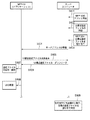
図1は本発明の実施形態にかかるMFPとサーバコンピュータとからなるシステムの構成を示す図である。図1において、100はJava(登録商標)環境に適用可能なMFPである。101はネットワークであり、102はサーバコンピュータである。サーバコンピュータ102上において、MFP100との通信を担うプログラムや、MFP100に提供するUIを構築するためのファイル生成プログラム、文書管理サーバ、コンテンツサーバとして機能するためのサーバアプリケーションが動作する。103はサーバコンピュータ102が利用可能な格納手段として機能する、データベースシステムあるいはファイルストレージシステムである。格納手段103のデータベースシステムには、種々の商品情報やその画像情報を格納することが可能である。サーバコンピュータ102は、MFP100からの指定によりカタログを生成する際に、指定された商品に関する情報をデータベースシステムから検索し、検索した情報に基づいて、商品情報や画像情報の配置を決定してカタログを生成することができる。この処理は、サーバコンピュータ102のサーバアプリケーションの機能により提供される。
(System configuration)
FIG. 1 is a diagram showing a configuration of a system including an MFP and a server computer according to an embodiment of the present invention. In FIG. 1,
104はサーバコンピュータ102に接続してオペレータが処理を行うクライアントPCである。例えば、オペレータは、クライアントPC104を介して、予め、MFP100に提供するUIを構築するための項目(例えば、商品の指定欄、差込み広告欄、印刷品質欄、文書種別欄等)を指定することが可能である。サーバコンピュータ102上サーバアプリケーションは、クライアントPC104で指定された項目により、UI構成設定ファイルを生成し、サーバコンピュータ102のHDD406(図4)に登録することができる。
A
尚、UIを構築するための項目の指定、UI構成設定ファイルの生成と登録は、サーバコンピュータ102で行うことも可能である。
It should be noted that specification of items for constructing a UI and generation and registration of a UI configuration file can also be performed by the
図2は、図1に示したMFP100の詳細な構成を説明する図であり、200は原稿自動送り部(以下、「フィーダ」)、201は原稿スキャニング部、202はディスプレイ・タッチパネル部、203は給紙部である。また、204は定着部、205は排紙部、206はフィニッシング装置、207は排紙トレイそして208はプリントエンジン部である。
2 is a diagram for explaining the detailed configuration of the
(MFP100における情報処理機能の論理構成)
図3は、MFP100における情報処理機能の論理構成を示すブロック図である。300はユーザに対しユーザインタフェース(UI)を提供するディスプレイ・タッチパネル部であり、301はネットワーク101を介して外部機器と通信を行うネットワークインタフェース部である。302はMFP100を制御するプログラムを実行するCPUであり、303は組込済みプログラムおよびデータが記録されているROMである。304はCPUやプログラムの処理において利用可能なメモリ領域であるRAMであり、305は大容量記憶領域のHDDであり、各部は入出力インターフェース306を介して接続されている。
(Logical configuration of information processing function in MFP 100)
FIG. 3 is a block diagram showing a logical configuration of the information processing function in
(サーバPC及びクライアントPCにおける情報処理機能の論理構成)
図4は、図1において示したサーバコンピュータ(PC)102およびクライアントPC104における情報処理機能の論理構成を示すブロック図である。400はユーザから入力を受け付けるキーボード・マウスの入力制御部、401はユーザに出力画面を提供するディスプレイ部である。402はネットワークを介して外部機器と通信を行うネットワークインタフェース部、403は制御プログラムを実行するCPUである。404は組込済みアプリケーション及びデータが記録されているROM、405はCPUやアプリケーションの処理において利用可能なメモリ領域であるRAMである。406は大容量記憶装置のHDDであり、各部は入出力インターフェース407を介して接続されている。
(Logical configuration of information processing function in server PC and client PC)
FIG. 4 is a block diagram showing a logical configuration of information processing functions in the server computer (PC) 102 and the
(MFP100のソフトウェア構成)
図5は、MFP100において実行可能なアプリケーションプログラムに関するソフトウェア構成を示す図である。ソフトウェア構成は、MFP100の各種機能をリアルタイムに制御可能なリアルタイムOS501の各モジュール、或いは、CPU302に命令してMFP100の各機能を制御することが可能なライブラリ群より構成される。MFP100の各機能は、その上位で動作するアプリケーションに対して、インターフェース・コマンドを提供するモジュール群により実現されるものである。502はリアルタイムOS501上で動作するコントローラ制御部であり、MFP100を構成するスキャニング部201、プリントエンジン部208、モデム通信部、PDL展開部などを制御する各モジュールにより構成されるものとする。503はアプリケーション・プログラミング・インターフェース(以下、API)である。API503は、アプリケーションからの命令の入力に応答して、コントローラ制御部502にアクセスするための処理と、ネットワークインタフェース301を制御する機能を有する。504は、特定のアプリケーションを実行するために最適な実行環境であり、例えば、Java(登録商標)の仮想マシンなどにより実現されるものである。505は実行環境504が使用する資源を管理するリソース管理部であり、リアルタイムOS501上で動作する。リソース管理部505は、実行環境を実現する仮想マシン504自身、API503、或いはリアルタイムOS501上の全アプリケーションがメモリ等のリソース資源を使用する際、予め決められた以上の資源が使用できないように制限するものである。506、507、508は、MFP100において動作可能なアプリケーション群の一例である。以降の説明においては、対象アプリケーションを506(アプリケーションA)であるとする。
(Software configuration of MFP 100)
FIG. 5 is a diagram illustrating a software configuration related to an application program that can be executed in the
(UI構築に関する動作シーケンス)
図6は、カスタマイズされたUIを構築する動作シーケンスを示す図である。ステップS601において、管理者はサーバコンピュータ102にMFP100のアドレス登録を行い、ステップS602において、UI構成設定ファイルを登録する。
(Operation sequence related to UI construction)
FIG. 6 is a diagram illustrating an operation sequence for constructing a customized UI. In step S601, the administrator registers the address of the
ステップS603において、サーバコンピュータ102は、MFP100へ、先のステップS602で登録されたUI構成設定ファイルを割り当てる。
In step S <b> 603, the
ステップS604において、サーバコンピュータ102は、アプリケーション506が動作しているMFP100に対し、サーバコンピュータ102自身のサーバアドレスを登録する。
In step S604, the
ステップS605において、MFP100のアプリケーション506は、先のステップS604において登録されたサーバアドレスに対し、UI構成設定ファイル取得要求をサーバコンピュータ102に送信する。
In step S605, the
ステップS606において、サーバコンピュータ102は、MFP100に割り当てたUI構成ファイルを読み出し、MFP100のアプリケーション506は、UI構成設定ファイルをサーバコンピュータ102よりダウンロードする。
In step S <b> 606, the
ステップS607において、アプリケーション506は、ダウンロードしたUI構成設定ファイルをHDD305に保存し、UI構成設定ファイルの内容を解析する。そして、その解析の結果に基づいて、UIを構築する(S608)。
In step S607, the
同様の手順に従い、サーバコンピュータ102は、他のMFPに対して、任意のUI構成設定ファイルを登録し、割り当てることが可能である。また、他のMFPは、個別に割り当てられたUI構成設定ファイルに従って、ユーザの用途に応じたユーザインタフェース画面を構築することが可能である(S609)。
According to the same procedure, the
(UI画面の例)
図7は、アプリケーション506がMFP100のディスプレイ・タッチパネル部202上において提供するUI700の一例を示す図である。このUI700の例は、デジタルカメラの広告作成を印刷の対象とするものである。図7において、701は、アプリケーション名の表示とアプリケーションの選択が可能な表示・選択部であり、表示・選択部701を選択すると、例えば、プルダウンメニュー中に選択可能なアプリケーションが表示される。表示・選択部701の操作により、アプリケーションの切り替えを行うことが可能である。702は、ディスプレイ・タッチパネル部202に表示されるUI700のフレームを示している。703は商品の指定欄を示し、704は、差込み広告の指定欄を示し、そして、705は、印刷品質の指定欄を示す。703〜705の各指定欄は、デジタルカメラの広告作成を対象とした例示的な指定内容を示す欄であり、本発明の趣旨は、この表示内容に限定されるものでないことは言うまでもない。すなわち、MFP100の各アプリケーションは、ユーザの用途に応じたUI構成設定ファイルの内容に基づいて、ユーザの要求仕様に適したユーザインタフェース画面を構築することができるものとする。
(Example of UI screen)
FIG. 7 is a diagram illustrating an example of a
706は、サーバコンピュータ102で生成された指定情報ファイルに基づく印刷出力を指定するコントロールボタンである。コントロールボタン706が押下されると、各指定欄(703、704)で指定された商品等に対応する各データが引数として、サーバコンピュータ102に送られる。ここで、サーバコンピュータ102に送られる各データが、カタログ生成のためのカタログ生成情報となる。サーバコンピュータ102が生成したカタログは、MFP10にダウンロードされ、CPU302の制御の下、印刷処理が実行される。このサーバコンピュータ102とMFP100とが連携したプル型印刷処理の詳細は、図11の参照により後に詳細に説明する。
(UI構成設定ファイルの例)
図8及び図9は、UI構成設定ファイルの一部をXML(Extensible Markup Language)形式で表現した例を示す図である。図8のXML800の場合、ルートノードUIConfiguration(801)には、Componentsノード(802)とActionMappingノード(803)とが含まれている。ここで、Componentsノード(802)には、UIを構築するためのUI構成情報が含まれており、ActionMappingノード(803)には、UIから指示された処理を実行するためのアクション呼出の情報(機能選択情報)が含まれている。
(Example of UI configuration file)
8 and 9 are diagrams illustrating an example in which a part of the UI configuration setting file is expressed in an XML (Extensible Markup Language) format. In the case of the
Componentsノード(802)中のUI構成情報として、例えば、804は図7におけるUI表示を構成するパネルの要素(Panel)を識別する識別情報であり、809はパネルの表示位置、サイズ等を具体的に特定するための属性情報である。CPU302の制御の下、アプリケーション506は、識別情報804と、この識別情報804に対応する属性情報809と、に基づいて、UIの構成要素の表示を制御して、UIを構築することができる。
As UI configuration information in the Components node (802), for example, 804 is identification information for identifying a panel element constituting the UI display in FIG. 7, and 809 is a specific display position and size of the panel. It is attribute information for specifying. Under the control of the
XML800には、商品の指定欄のUIを構成するための構成要素として、識別情報(List)805が記述され、対応する属性情報810により、商品指定欄の表示位置、サイズ等が具体的に特定される。CPU302の制御の下、アプリケーション506は、識別情報805と属性情報810とに基づいてUI中の商品指定欄の表示を制御して、UIを構築することができる。
In the
また、XML800には、差込み広告の指定欄のUIを構成するための構成要素として、識別情報(List)806が記述され、対応する属性情報811により、差込み広告指定欄の表示位置、サイズ等が具体的に特定される。CPU302の制御の下、アプリケーション506は、識別情報806と属性情報811とに基づいてUI中の差込み広告指定欄の表示を制御して、UIを構築することができる。
Also, in the
更に、印刷品質指定欄のUIを構成するための構成要素として、識別情報(Choice)807が記述され、対応する属性情報812により、印刷品質指定欄の表示位置、サイズ等が具体的に特定される。CPU302の制御の下、アプリケーション506は、識別情報807と属性情報812とに基づいてUI中の印刷品質指定欄の表示を制御して、UIを構築することができる。
Further, identification information (Choice) 807 is described as a component for configuring the UI of the print quality designation field, and the display position, size, etc. of the print quality designation field are specifically specified by the
印刷開始を指示するためのボタン要素をUIの構成要素として、識別情報(Button)808が記述され、対応する属性情報813により、ボタン要素の表示位置、サイズ等が具体的に特定される。ラベル情報814には、ボタン要素に付加表示される内容が記述されている。CPU302の制御の下、アプリケーション506は、識別情報808、属性情報813、ラベル情報814と、に基づいてUI中のボタン要素の表示を制御して、UIを構築することができる。
Identification information (Button) 808 is described using a button element for instructing the start of printing as a component element of the UI, and the display position, size, and the like of the button element are specifically specified by corresponding
尚、各構成要素の表示において、表示すべきテキストなどの参照情報がDataRef要素として記述されている。アプリケーション506は、上述の識別情報、属性情報に加えて、表示すべきテキストなどの参照情報により、UIを構築することができるものとする。
In displaying each component, reference information such as text to be displayed is described as a DataRef element. The
図9(a)のXML900は、図8のXML800中における参照情報(DataRef要素)の内容を記述するものである。ルートノードDataSource(901)にはDataSet要素(902)とData要素(903、904、905)が含まれている。DataSet要素(902)の中で記述されているData要素(903、904、905)は、XML800における参照データ850に基づき、UIを構築するための表示データとして参照される。
図8のXML800において、815は、ボタン要素706が押下された場合(コントロールイベント発生時)に実行するべき動作(Target Action)を記述する。コントロールイベント発生時に実行するべき動作として、815においては、"act_001"が記述されている。ボタン要素706が押下され、コントロールイベントが発生すると、Action Mappingノード(803)中のアクション要素(Action)の属性"id=act_001"が参照される。属性"id=act_001"は、呼出アクション名(name)、アクションの属性(type)を定義する(870)。ここで、アクションの属性(type)として利用可能なものとしては、例えば、プログラムモジュールの関数名、URIなどが挙げられる。
In the
アクション要素(Action)中には、更に、Argumentsノードが含まれ、各指定欄の表示からユーザが選択または入力したデータをアクションの引数として与えることが可能である(820、821、822)。 The action element (Action) further includes an Arguments node, and data selected or input by the user from the display of each designation column can be given as an argument of the action (820, 821, 822).
例えば、商品指定欄703で、ユーザが「DIGITAL C55」の項目を指定した場合、図9のXML900において「DIGITAL C55」に対応するデータ「0622A001」が、引数として与えられる。アプリケーション506はこの引数を読み込む。送信指示があると、この後に説明するサーバ装置のダイナミックレイアウトエンジンに対して送信する。
For example, when the user designates the item “DIGITAL C55” in the
図8及び図9は、UI構成設定ファイルの例示であり、本発明の趣旨はこの構成に限定されるものでないことはいうまでもない。UI構成設定ファイルの記述を変更することにより、アプリケーション506は、UIの構成を柔軟に変更することが可能である。
8 and 9 are examples of UI configuration setting files, and it goes without saying that the gist of the present invention is not limited to this configuration. By changing the description of the UI configuration setting file, the
また、UI構成設定ファイルはXML形式に限定されるものではなく、例えば、テキストファイル、バイナリファイル、データストリームなどの形式により記載してもよい。 The UI configuration setting file is not limited to the XML format, and may be described in a format such as a text file, a binary file, or a data stream.
UIがユーザによって操作されると、操作に対応するMFP100固有の機能の呼び出しに必要なデータは、UI構成設定ファイル中のComponentsノード(802)とAction Mappingノード(803)と間で受け渡される。そして、UIの操作に対応するサーバアプリケーションの機能の呼び出しに必要なデータは、MFP100とサーバコンピュータ102との間で受け渡される。これにより、MFPの機能を制御するとともに、サーバアプリケーションと連携する機能を制御することが可能になる。
When the UI is operated by the user, data necessary for calling a function specific to the
(アプリケーション506の論理的構成)
図10は、アプリケーション506の論理的構成を示す図である。1000はアプリケーション全体である。
(Logical configuration of application 506)
FIG. 10 is a diagram illustrating a logical configuration of the
ステップS1051において、UI構成設定ファイル受信/解析部1002がサーバコンピュータ104からダウンロードしたUI構成設定ファイルを受信し、その内容を解析する。
In step S1051, the UI configuration setting file reception /
ステップS1052において、UI構成設定ファイル受信/解析部1002は、解析済みであるUI構成設定ファイルのデータを記憶領域1003、1006に格納する。UIを構築するための各構成要素(コントロール)に関する設定値(属性情報等)のキャッシュデータは記憶領域1003に格納され、UIから指定されるアクションのマッピングデータは、記憶領域1006に格納される。
In step S1052, the UI configuration setting file reception /
ステップS1053において、UI構築部1004は、記憶領域1003のデータ(識別情報と、属性情報等)を参照して、UIを構築するための各構成要素(各コントロール)を生成しUI1001を構築する(S1054)。ここで、各コントロールは、例えば、図7で示した703、704等の構成要素として生成される。図10においては、UI1001の構成要素としてn個のコントロール(Control 1、2、3・・・n)が生成されている。
In step S1053, the
構築されたUIの各構成要素(コントロール(Control 1、2、3・・・n))がユーザによって操作、設定されると(S1055)、操作、設定されたコントロール要素からイベント(操作、設定に対応したコマンド)が発生する。そして、このイベントは、イベント・ハンドル部1005に通知される(S1056)。
When each component (control (
イベント・ハンドル部1005は、記憶領域1006のマッピングデータを参照し、該当するコントロール(操作、設定)に割り当てられているアクションを呼び出す。イベント・ハンドル部1005は、発生したイベントに対応するアクションを実行するための機能を選択し、アプリケーション506の内部の機能モジュール群1007a、b、c等を呼び出すことができるものとする。
The
例えば、機能モジュール1007aは、APIなどを介してMFPの機能1008を利用したり、サーバアプリケーションで提供している機能1009などを利用するよう構成しておくことが可能である。
For example, the
ここで、MFP100の機能としては、印刷機能や、ファクシミリ機能、スキャン機能等が含まれ、各機能を機能モジュール群1007a、b、cに割り当てることにより、選択的にMFP100の機能を利用することができる。
Here, the functions of the
MFP100の印刷機能と連携したサーバアプリケーションの機能としては、UIから指定されたデータ検索、データのレイアウト、レイアウトされたファイルを印刷の対象として生成し、ダウンロードする機能等が含まれる。また、MFP100のスキャン機能と連携したサーバアプリケーションの機能としては、スキャニング部201より入力されたデータの登録処理に関する機能が含まれる。
The functions of the server application linked with the printing function of the
(MFPとサーバコンピュータの連携)
次に、図7のUI700の例を用いて、アクションの呼出からMFP100の印刷機能、サーバアプリケーションのデータ検索、レイアウト、ファイル生成機能を利用したプル型印刷の例を図11のシーケンス図を参照して説明する。
(Cooperation between MFP and server computer)
Next, referring to the sequence diagram of FIG. 11, an example of pull-type printing using the print function of the
ステップS1151において、ユーザはUI700を利用して、各コントロール(商品指定欄703、差込み広告の指定704、印刷品質指定欄705)により、デジタルカメラの商品名、差込み広告、印刷品質の指定をする。そして、プリント開始がボタンコントロール706から指示されると、イベントが発生し、アクションのマッピングデータの参照により該当するアクションが機能モジュール群1007a、b、cから選択される。
In step S1151, the user uses the
ステップS1152において、選択された機能モジュール1007aが呼び出され、処理が開始される。このとき、機能モジュール1007aに通知されるリクエストをXMLで表現した例が図9(b)の901である。ルートノードAction(924)には、名称(Name)ノード925と、引数(Arguments)ノード926とが含まれている。引数ノード926以下の各引数要素(931〜933)に引数データを与えて、機能モジュールを呼び出すことができる。引数要素中において、属性keyにより、各引数要素(931〜933)の内容を識別することが可能である。このため、複数の引数要素に関するデータを一括して処理することが可能である。機能モジュール1007aは、アクションの呼び出しリクエストを解析して、コンテンツファイル生成要求(機能要求情報)を生成し、サーバアプリケーションに送信する(S1153)。コンテンツファイル生成要求の内容は、機能モジュール1007aに通知されるリクエスト(図9(b))の内容に基づくものである。
In step S1152, the selected
コンテンツファイル生成要求をXMLで表現した例が図11の1100である。ルートノード(Request)(1101)には、名称(Name)ノード(1102)と引数(Arguments)ノード(1103)が含まれている。引数ノード(1103)中の各引数には引数データが与えられている。 An example of a content file generation request expressed in XML is 1100 in FIG. The root node (Request) (1101) includes a name (Name) node (1102) and an argument (Arguments) node (1103). Argument data is given to each argument in the argument node (1103).
引数データは、カスタマイズされたUIで選択されたデータであり、このデータがサーバアプリケーションに受け渡される。サーバアプリケーションは受け渡された引数データを利用して、データ検索、レイアウト、ファイル生成機能を実行する。図7で、例えば、商品名DIGITAL C55が選択され、挿し込み広告の指定として、「お薦めプリンタ」が選択された場合を考える。上述したように、前記の操作パネルの指示に応じて引数「0622A001」および差込み広告種別「AdvPrinter」が特定情報として準備される。アプリケーションは操作パネルの送信ボタンが押されると、準備した引数をサーバ装置102に送信してレイアウトエンジンに渡す。
The argument data is data selected by the customized UI, and this data is transferred to the server application. The server application uses the passed argument data to execute data search, layout, and file generation functions. In FIG. 7, for example, consider a case where the product name DIGITAL C55 is selected and “recommended printer” is selected as the insertion advertisement designation. As described above, the argument “0622A001” and the insertion advertisement type “AdvPrinter” are prepared as specific information in accordance with the instruction from the operation panel. When the transmission button on the operation panel is pressed, the application transmits the prepared argument to the
これらのデータに基づき、サーバコンピュータ102は、レイアウトエンジンを呼び出して、自動的に文字データ、画像データ等がレイアウトされたファイルを生成する(S1156)。 以下、ステップS1156の詳細を図19を用いて説明する。
Based on these data, the
図19は、本発明が適用できる、データベースと差込フィールドを有する文書をレイアウトエンジンで出力する手法を説明する図である。1901は、差込フィールドおよび広告フィールドを有する文書(ドキュメントテンプレート)の例を示している。この例においては、1901は、「商品名」データを差し込むためのフィールド1902「差込フィールドA」、「商品コード」データを差し込むためのフィールド1903「差込フィールドB」、「商品画像」データを差し込むためのフィールド1904「差込フィールドC」、広告を差し込むためのフィールド1905「広告エリア」を有している。
FIG. 19 is a diagram for explaining a method of outputting a document having a database and insertion fields to the layout engine, to which the present invention can be applied.
データベース1906は、前期の各差込フィールド1902〜1905用のデータを格納するデータベースである。このデータベースには少なくとも1907差込データ管理テーブルと、1909広告データ管理テーブルと、1908広告―商品関連付け管理テーブルが存在する。1907差込データ管理テーブルは、前記の差込フィールド1902〜1904にそれぞれ差し込まれるデータを管理するテーブルであり、フィールド1902「差込フィールドA」にはキー1911「DATA_A」、フィールド1903「差込フィールドB」にはキー1912「DATA_B」、そしてフィールド1904「差込フィールドC」にはキー1913「DATA_C」がそれぞれ関連付けられる。
The
1909広告データ管理テーブルは、1905に差し込まれるデータを管理し、1919〜1921といったフィールドで構成される。1908広告―商品関連付け管理テーブルでは、フィールド1921と、フィールド1912またはフィールド1914とを関連付けている。つまり、広告カテゴリフィールド1915は、商品カテゴリフィールド1916または商品コードフィールド1917とを関連付けていることを示している。
The 1909 advertisement data management table manages data inserted into 1905 and includes
MFP100から送信されてきた商品コード「0622A001」および差込み広告種別「AdvPrinter」がデータとして渡されるので、これらを検索条件として、データベース管理テーブル1907〜1909が検索され、ドキュメントテンプレートの差込フィールド1902〜1904にそれぞれ、「DIGITAL C55」「0622A001」「DigitalCamera-A.jpg」の文字列データおよび画像データが差し込まれ、広告エリア1905には、「AdvPrinter-A.jpg」の広告画像データが差し込まれ、レイアウトエンジンにより最適な文字サイズ、画像サイズに自動レイアウトされ、ファイルとして出力される。なお、この動的レイアウトは、静的なものではない。動的レイアウトは、差し込まれる差込みデータのデータ量、例えば、DigitalCamera-A.jpgの枠サイズの大きさ、差し込まれる文字列の数に応じて、差込データのレイアウトが適切に決定されるものである。この際、テンプレート内にある広告画像の配置場所の目安を定めたレイアウト情報も考慮される。
Since the product code “0622A001” and the insertion advertisement type “AdvPrinter” transmitted from the
このファイルは、電子文書のためのフォーマットであるPDF(Portable Document Format)などを用いることも可能である。また、電子文書フォーマットとしてページ記述言語(PDL)などを利用することも可能である。アプリケーション506は、ファイルの取得要求をサーバアプリケーションに送信し(S1157)、サーバアプリケーションによって生成されたファイルをダウンロードする(S1158)。アプリケーション506は、APIなどを介してMFPの機能1008を呼び出し、PDL展開処理、印刷処理を行う(S1159、S1160)。この際、XML901の引数データとして与えられた印刷品質(print_quality_dpi)が使用され、MFP100の印刷機能が制御される。図9(b)の場合、印刷品質として600dpiが設定されているので、この指定に基づいて、印刷機能が制御される。アクション呼び出しによる全ての処理が完了すると、UIに処理の完了が表示される。この際、表示の代わりに、処理の記録を残すようにすることも可能である(S1161)。結果の表示または記録が終了すると一連のアクション処理が完了する(S1162)。
This file can also use PDF (Portable Document Format) which is a format for electronic documents. Also, a page description language (PDL) or the like can be used as the electronic document format. The
ここでは、レイアウトエンジンを用いた、商品データと広告データの動的な差込文書の生成を例示したが、本発明の適用範囲は、サーバコンピュータの任意の提供機能をMFPから利用することであり、この例だけにとどまるものではない。 In this example, the generation of a dynamic insertion document of product data and advertisement data using the layout engine is illustrated. However, the scope of the present invention is to use any provided function of the server computer from the MFP. This is not the only example.
尚、上述のステップS1153、S1157及びS1158において、MFP100とサーバコンピュータ102との間の通信は、暗号化手段の適用により暗号化して情報の機密を保持することも可能である。
In steps S1153, S1157, and S1158 described above, communication between the
(UIの表示例)
MFP100の各アプリケーションは、ユーザの用途に応じたUI構成設定ファイルの内容に基づいて、ユーザの要求仕様に適したユーザインタフェース画面を構築することが可能である。ここで、図7に示したUIとは異なる表示形式のUIの例を、図16乃至図18の参照により説明する。
(UI display example)
Each application of the
図16(a)は、商品のカテゴリを指定するためのUI1600を示す図であり、指定欄(1601)からは、「デジタルカメラ」、「プリンタ」、「ファックス」等を選択することができる。このUI1601からデジタルカメラを選択して、ボタンコントロール「次へ」(1602)をクリックすると、UI1601が切り替えられ、図16(b)のUI1604が表示される。図16(b)は、先のUI1601で指定された商品カテゴリ(デジタルカメラ)の中で、具体的な商品を指定するためのUI1604を示す図である。図16(b)のUIにおいて、ボタン「プリント」(1605)を入力すると、先に説明した図7のプリント706と同様の印刷処理に移行する。また、UI構成設定ファイルの内容により、アプリケーションは、図16(b)に続くUIを更に構築することも可能である。
FIG. 16A is a diagram showing a
図17及び図18は、図16のUI表示に関するUI構成設定ファイルの例を示す図である。図17のXML1700の場合、ルートノードUIConfiguration(1701)には、Componentsノード(1702)とActionMappingノード(1703)とが含まれている。ここで、Componentsノードには、UIを構築するためのUI構成情報が含まれており、ActionMappingノードには、UIから指示された処理を実行するためのアクション呼出の情報(機能選択情報)が含まれている。
17 and 18 are diagrams illustrating examples of UI configuration setting files related to the UI display of FIG. In the case of
UI1600内のボタンコントロール「次へ」(1602)がクリックされるとイベント(クリック操作に対応するコマンド)が発生する。そして、Target Action 1710で記述されているAction Mappingノード(1703)中のアクション要素(Action)の属性"id=act_001"が参照される。この際、アクション要素の属性は、「forward」(画面遷移)(1705)、遷移先は「panel_02」(次のUIパネル)(1705)として記述されている。UI構成情報の中から、「panel_02」の識別情報が検索され、対応する商品リストの属性情報(1706)、参照情報(1707)に基づいて、図16(b)のUI1603が構築される。
When the button control “next” (1602) in the
図18のXML1800は、図17のXML1700中における参照情報(DataRef要素)の内容を記述するものである。ルートノードDataSource(1801)にはDataSet要素(1802)とData要素(1803、1804、1805)が含まれている。データセット1802の中で記述されているデータ1803〜1805は、XML1700における参照データ1750に基づき、UIを構築するための表示データとして参照される。
The
また、アプリケーションは、「panel_02」に関する参照情報(データ1806〜1809)の中から、ユーザが指定した項目と合致する商品カテゴリのデータ1806〜1808を検索して、商品指定欄1604に表示する。
Further, the application searches the
図16乃至図18のようにUI構成設定ファイルの内容を変更することにより、ユーザの要求仕様に適した表示形式で、ユーザインタフェース画面を構築することが可能である。図16のボタン「プリント」(1605)をクリックすると、イベントが発生し、先に説明した図7のプリント706と同様の印刷処理に移行する。
By changing the contents of the UI configuration setting file as shown in FIGS. 16 to 18, it is possible to construct a user interface screen in a display format suitable for the user's required specifications. When the button “print” (1605) in FIG. 16 is clicked, an event occurs, and the process proceeds to the print processing similar to the
本実施形態によれば、ユーザの用途に応じたユーザインタフェース画面を構築し、ユーザインタフェース画面からの設定によりMFP固有の機能やサーバアプリケーションの機能を利用した画像形成が可能になる。 According to the present embodiment, a user interface screen corresponding to the user's application can be constructed, and image formation using functions unique to the MFP and server application functions can be performed by setting from the user interface screen.
(第2実施形態)
次に、本発明の第2実施形態を図12乃至図15の参照により説明する。本実施形態では、MFP100のスキャナ機能を利用して入稿したスキャン文書ファイルをサーバアプリケーションによって、格納手段として機能するファイルストレージシステム103に登録する実施形態を説明する。システム構成、アプリケーションの論理構成等に関して、第1実施形態と重複する内容の説明は省略する。
(Second Embodiment)
Next, a second embodiment of the present invention will be described with reference to FIGS. In this embodiment, an embodiment will be described in which a scanned document file submitted using the scanner function of the
図12は、第1実施形態の図7と同様に、アプリケーション506がMFP100のディスプレイ・タッチパネル部202において提供するUIの一例を示す図である。このUIの例では、文書種別(1203)、サーバ登録処理(1204)、スキャン解像度(1205)、プレビュー画像での確認(1206)の指定をすることができる。MFP100のスキャニング部201は、原稿台もしくはフィーダ200(図2)にセットされた原稿を、指定された解像度でスキャンしてスキャン文書ファイルを生成する。このスキャン文書ファイルは、ディスプレイ・タッチパネル部202のプレビュー画面にて表示され、ユーザの確認に従いサーバコンピュータ102に送信される。
FIG. 12 is a diagram illustrating an example of a UI provided by the
そして、サーバコンピュータ102は、UI1200で指定された登録処理を行い、指定された文書種別のデータとして、格納手段として機能するファイルストレージシステム103に登録する。
Then, the
図12のUI1200において、1201はアプリケーション名の表示とアプリケーションの選択が可能な表示・選択部であり、表示・選択部1201を選択すると、例えば、プルダウンメニュー中に選択可能なアプリケーションが表示される。表示・選択部1201の操作により、アプリケーションの切り替えを行うことが可能である。1202は、ディスプレイ・タッチパネル部202に表示されるUI1200のフレームを示している。
In the
1203は文書種別の指定欄を示し、1204はサーバ登録処理の指定欄を示し、1205はスキャン解像度の指定欄を示す。1206はプレビュー画面での確認の有無の指定欄であり、1207はスキャン入力した文書ファイルをサーバコンピュータに登録するコントロールボタンである。
尚、本発明の趣旨は、この表示内容に限定されるものでないことは言うまでもない。すなわち、MFP100の各アプリケーションは、ユーザの用途に応じたUI構成設定ファイルの内容に基づいて、ユーザの要求仕様に適したユーザインタフェース画面を構築することができるものとする。
Needless to say, the gist of the present invention is not limited to this display content. In other words, each application of
図13及び図14は、UI構成設定ファイルの一部をXMLで表現した例を示す図である。UI構成設定ファイルで記述された内容に従い、MFP100のアプリケーションは、UIを構築することができる。図13のXML1300の場合、ルートノードUIConfiguration(1301)には、Componentsノード(1302)とActionMappingノード(1303)とが含まれている。Componentsノード(1302)には、UIを構築するためのUI構成情報が含まれており、ActionMappingノード(1303)には、UIから指示された処理を実行するためのアクション呼出の情報(機能選択情報)が含まれている。
13 and 14 are diagrams illustrating an example in which a part of the UI configuration setting file is expressed in XML. In accordance with the contents described in the UI configuration setting file, the application of the
各構成要素を識別する識別情報と、識別情報に対応する属性情報とに基づいて、MFP100のアプリケーションは、UIの構成要素の表示を制御して、UIを構築することができる。
Based on the identification information for identifying each component and the attribute information corresponding to the identification information, the application of the
図14(a)のXML1400は、図13のXML中における参照情報(DataRef要素)の内容を記述するものである。ルートノードDataSource(1401)にはDataSet要素(1402)とData要素(1403、1404、1405)が含まれている。
ボタン群は要素として定義される。要素は、要素名と属性を含む。要素はそれぞれ子要素を従えることが出来る。まず、DataSetというのが要素名である。DataSetはidという属性を持つ。属性には値を入れることが出来る。図14にId=id_ds001とあるが、要素名DataSetの付加的情報として定義される属性idが「id_ds001」なる値を取るという意味である。また、子要素としてDataが定義されている。Dataはさらに子要素として、Label要素と、Value要素を持つ。XMLデータの解析の結果、Label要素にセットされる文字列は、ボタンの表示名として用いられる。Value 要素は、属性としてkeyを持つ。Key属性は、文書種別を指定するものである。例えば、領収書ボタンを押下すると、MFP100は、key属性として、Recieptなる文字列がMFP100に取得される。この取得された文字列を、送信指示に応じて、MFP100は、サーバコンピュータに送信しても良い。
Buttons are defined as elements. An element includes an element name and an attribute. Each element can have child elements. First, DataSet is the element name. DataSet has an attribute called id. An attribute can contain a value. In FIG. 14, Id = id_ds001 means that the attribute id defined as additional information of the element name DataSet takes the value “id_ds001”. Data is defined as a child element. Data further has a Label element and a Value element as child elements. The character string set in the Label element as a result of the analysis of the XML data is used as the display name of the button. The Value element has key as an attribute. The Key attribute specifies the document type. For example, when the receipt button is pressed, the
更に、Dataset要素の属性id_ds0102を持つ要素について説明する。これは、スキャナで読み込んだデータを、サーバコンピュータでどのような加工をしたいかを指示するボタン群1204に関する。例えば、Labelの電子署名の要素が解析されると、電子署名の文字列を含むボタンが表示される。また、value要素の属性keyに対して値save optionがセットされている。また、value要素の内容として、eSignitureが設定されている。電子署名ボタンが一度押された状態で、送信ボタンが押されると、eSignatureなる文字列が、save_optioinの値としてサーバコンピュータに送信されることになる。サーバコンピュータは、データに付加されたsave_optionの値がeSigunatureである場合は、電子署名処理をサーバコンピュータで行う。Save_optionの値がTime_Stampである場合は、タイムスタンプ処理をサーバコンピュータで行う。
Further, an element having the attribute id_ds0102 of the Dataset element will be described. This relates to a
次に、3つ目のDataSet(id属性がid_0203)について説明する。同様にLabel要素は、ボタンとして表示される。そして、選択されたValueの内容(600、200などから選択された数字情報)は、選択された解像度として、MFP100に取得される。例えば、MFP100は、300dpiのボタンが押されると、300DPIの解像度でドキュメントのスキャン処理を行う。
Next, the third DataSet (id attribute is id_0203) will be described. Similarly, the Label element is displayed as a button. Then, the content of the selected Value (numerical information selected from 600, 200, etc.) is acquired by the
ここで、UI構成設定ファイルの記述に関する具体的な説明は、図7及び図8と重複するため省略する。 Here, a specific description regarding the description of the UI configuration setting file is omitted because it overlaps with FIGS.
(MFPとサーバコンピュータの連携)
次に、図12のUI1200の例を用いて、アクションの呼出からMFP100のスキャン機能、サーバアプリケーションのコンテンツ登録機能を利用した例を図15のシーケンス図を参照して説明する。
(Cooperation between MFP and server computer)
Next, an example using the scan function of the
ステップS1551において、ユーザはUI1200を利用して、文書種別1203、サーバ登録処理1204、スキャン解像度1205、プレビュー画像での確認1206の指定を指定する。そして、スキャン・登録をボタンコントロール1207より指示すると、イベントが発生し、アクションのマッピングデータの参照により該当するアクションが機能モジュール群1007a、b、cから選択される。
In step S1551, the user uses the
ステップS1552において、選択された機能モジュール(ここでは、スキャン機能に対応した機能モジュール1007cとする)が呼び出され、処理が開始される。このとき、機能モジュール1007cに通知されるリクエストをXMLで表現した例が図14(b)の1410である。ルートノードAction(1424)には、名称(Name)ノード1425と、引数(Arguments)ノード1426とが含まれている。引数ノード1426以下の各引数要素(1431〜1435)に引数データを与えて、機能モジュールを呼び出すことができる。引数要素中において、属性keyにより、各引数要素(1431〜1435)の内容を識別することが可能である。このため、複数の引数要素に関するデータを一括して処理することが可能である。機能モジュール1007cは、アクションの呼び出しリクエストを解析し、指定された解像度で原稿をスキャン入力するよう、API等を介してMFPの機能を制御する。機能モジュール1007cは、スキャン入力したデータに基づいて、スキャン文書ファイルを生成する(S1553)。
In step S1552, the selected functional module (here, the
ステップS1554において、プレビュー画面での確認が指定されている場合、アプリケーション506は、プレビュー画面をディスプレイ・タッチパネル部202上に表示させる。更に、必要である場合に、アプリケーション506は、ディスプレイ・タッチパネル部202上に確認ダイアログを表示させる。
If confirmation on the preview screen is specified in
ステップS1555において、機能モジュール1007cは、アクションの呼び出しリクエストを解析して、スキャン文書登録要求(機能要求情報)を生成し、サーバアプリケーションに送信する(S1555)。スキャン文書登録要求の内容は、機能モジュール1007cに通知されるリクエスト(図14(b))の内容に基づくものである。
In step S1555, the
更に、機能モジュール1007cは、サーバコンピュータ102上のサーバアプリケーションにスキャン文書登録要求を送信するとともに、スキャン文書ファイルをアップロードする。この際、スキャン文書登録要求をXMLで表現した例が1500である。ルートノード(Request)(1501)には、名称(Name)ノード(1502)と引数(Arguments)ノード(1503)が含まれている。引数ノード1503中の各引数には引数データが与えられている。
Further, the
引数データは、カスタマイズされたUIで選択されたデータであり、このデータがサーバアプリケーションに受け渡される。サーバアプリケーションは受け渡された引数データを利用して、コンテンツの登録に関する機能を実行する。 The argument data is data selected by the customized UI, and this data is transferred to the server application. The server application uses the passed argument data to execute functions related to content registration.
サーバアプリケーションは、スキャン文書登録要求を解析し、登録処理(save_option)の指定、電子署名(eSignature)、タイムスタンプ(TimeStamp)の指定の有無を検出する。スキャン文書登録要求1500には、登録処理の指定、電子署名、タイムスタンプが指定されているので、サーバアプリケーションは、指定に従いスキャン文書ファイルの電子署名、タイムスタンプ、登録の各処理を実行する。
The server application analyzes the scan document registration request and detects whether or not a registration process (save_option) is specified, an electronic signature (eSignature), and a time stamp (TimeStamp) are specified. Since the scan
すなわち、サーバアプリケーションは、ステップS1556において、電子署名処理を実行し、ステップS1557において、タイムスタンプ処理を実行し、ステップS1558において文書DBへの登録処理を実行する。文書DBに登録する際、サーバアプリケーションは、引数データで指定された文書種別(document_type)領収書(Receipt)として登録する。 That is, the server application executes electronic signature processing in step S1556, executes time stamp processing in step S1557, and executes registration processing in the document DB in step S1558. When registering in the document DB, the server application registers as a document type (document_type) receipt (Receipt) specified by the argument data.
ステップS1559において、サーバアプリケーションによる登録処理が完了すると、その処理結果がMFP100のアプリケーション506に通知される。
In step S1559, when the registration processing by the server application is completed, the processing result is notified to the
ステップS1560において、アクション呼び出しによる全ての処理が完了すると、アプリケーション506はUIに処理結果を表示する。この際、アプリケーション506は、UIへの表示の他、履歴を確認できるように処理結果の記録を残すことも可能である。
In step S1560, when all the processing by the action call is completed, the
一連のアクション処理の完了により、アプリケーション506の処理を終了する(S1561)。
Upon completion of the series of action processes, the process of the
尚、上述のステップS1555及びS1559において、MFP100とサーバコンピュータ102との間の通信は、暗号化手段の適用により暗号化して情報の機密を保持することも可能である。
Note that in steps S1555 and S1559 described above, communication between the
本実施形態によれば、ユーザの用途に応じたユーザインタフェース画面を構築し、ユーザインタフェース画面からの設定によりマルチファンクション機器固有の機能やサーバアプリケーションの機能を利用した画像形成が可能になる。 According to the present embodiment, a user interface screen corresponding to the user's application is constructed, and image formation using functions unique to the multifunction device and server application functions can be performed by setting from the user interface screen.
サーバコンピュータ102と通信するMFP100は、動的レイアウト機能を情報処理装置において実行させる指示を入力するための画面を操作部に表示する。ここで、動的レイアウト機能は、例えば、挿し込みデータと、挿し込みデータをレイアウトするためのレイアウト情報を含む、ドキュメントテンプレートをマージして画像形成するために、テンプレートデータに基づくレイアウトを動的に決定する機能である。
操作部(ディスプレイ/タッチパネル300)に表示される画面を介して入力される指示に応じて、サーバコンピュータ102の動的レイアウト機能を用いて処理する際に用いられる特定情報を、サーバコンピュータ102に対して送信する。特定情報として、商品コードおよび差込み広告種別を説明した。
The
In response to an instruction input via a screen displayed on the operation unit (display / touch panel 300), specific information used when processing using the dynamic layout function of the
当該特定情報を用いて、サーバコンピュータ102において動的レイアウトされたデータを受信する。また、MFP100は、受信したデータをプリントエンジンで出力する。
The
MFP100は、ユーザインタフェースを構成するための情報が設定されている構成データを取得する。そして、MFP100は、その構成データを解析する。そして、MFP100の操作部は、動的レイアウトを実行する指示を入力するための画面を表示する。
The
MFP100は操作部を介して、挿し込みデータとテンプレートデータとを特定するための特定情報を入力することが可能な装置である。そして、MFP100は、入力した特定情報を送信する。
The
送信した特定情報を用いて特定された挿し込みデータとテンプレートデータに基づきサーバコンピュータ102が動的レイアウトしたデータをMFP100が受信する。MFP100は、受信したデータをプリントエンジンを介して印刷出力する。
The
また、サーバ装置102と通信するMFP100は次のように構成するものとする。ユーザインタフェースを構成するための情報が設定されている構成データを取得するネットワークインタフェース301はMFPが備えるものとする。ネットワークインタフェース301を介して取得した構成データ(例えば、図13、図14に示すデータ)を処理して、MFP100のスキャナ機能を用いて処理されたデータをサーバコンピュータ102の機能を用いて処理する画像処理を実行する指示を入力するための画面を操作部(ディスプレイ/タッチパネル300)に表示する。操作部に表示される画面を介して入力される指示に応じて、スキャン処理をCPU302は実行する。さらに、CPU302がMFP100のスキャナ機能を実行して得られるデータと、当該データをサーバコンピュータ102の機能を用いて処理する際に用いられる処理情報(スキャン文書登録要求1500)を、サーバコンピュータ102に送信するネットワークインタフェース301をMFP100は備える。
Further, the
ディスプレイ/タッチパネル300は、MFP100がネットワークインタフェース301を用いて取得した構成データを解析して、MFP100のスキャナを用いて入力されたデータをサーバコンピュータ102に搭載されたプログラムを実行して画像処理を実行する指示を入力するための画面を表示する。
The display /
また、ディスプレイ/タッチパネル300が表示する画面を介して入力される指示に応じて、MFP100のスキャナ機能をCPU302の制御下にて実行する。
Further, the scanner function of the
CPU302がスキャナを実行して入力されるデータと、当該データをサーバコンピュータ102に搭載されるプログラムを用いて画像処理する際に用いられるパラメータ又はコマンド(スキャン文書登録要求1500)を、ネットワークインタフェース301を介して送信する。サーバコンピュータ102は送信された当該要求1500を受信する。
The data inputted by the
また、サーバコンピュータ102は、時刻を示す情報を付加するタイムスタンプ処理を提供するものとする。また、サーバコンピュータ102においてタイムスタンプ処理を実行する指示を行う指示画面をMFP100の操作部上に表示する。
Further, the
また、ディスプレイ/タッチパネル300を介したスキャナの操作指示に応じて、画像形成装置のスキャナ機能の処理がCPU302の制御の下に実行される。
Also, the scanner function process of the image forming apparatus is executed under the control of the
更に、ディスプレイ/タッチパネル300は表示されるユーザインタフェースの操作により設定された制御情報を含む処理情報(タイムスタンプ指示を含むスキャン文書登録要求1500)をサーバ装置102に送信手段が送信する。そして、MFP100のスキャナ機能により入力した画像データを送信して、サーバコンピュータ102にタイムスタンプ処理をさせて登録させる。
Further, the display unit /
(他の実施形態)
なお、本発明の目的は、前述した第1及び第2実施形態の機能を実現するソフトウェアのプログラムコードを記録した記憶媒体を、システムあるいは装置に供給しても達成される。また、システムあるいは装置のコンピュータ(またはCPUやMPU)が記憶媒体に格納されたプログラムコードを読出し実行することによっても、達成されることは言うまでもない。
(Other embodiments)
The object of the present invention can also be achieved by supplying a storage medium storing software program codes for realizing the functions of the first and second embodiments described above to a system or apparatus. Needless to say, this can also be achieved by the computer (or CPU or MPU) of the system or apparatus reading and executing the program code stored in the storage medium.
この場合、記憶媒体から読出されたプログラムコード自体が前述した実施形態の機能を実現することになり、そのプログラムコードを記憶したコンピュータ可読の記憶媒体は本発明を構成することになる。 In this case, the program code itself read from the storage medium realizes the functions of the above-described embodiments, and the computer-readable storage medium storing the program code constitutes the present invention.
プログラムコードを供給するためのコンピュータ可読の記憶媒体としては、例えば、フレキシブルディスク、ハードディスク、光ディスク、光磁気ディスク、CD−ROM、CD−R、磁気テープ、不揮発性のメモリカード、ROMなどを用いることができる。 As a computer-readable storage medium for supplying the program code, for example, a flexible disk, a hard disk, an optical disk, a magneto-optical disk, a CD-ROM, a CD-R, a magnetic tape, a nonvolatile memory card, a ROM, or the like is used. Can do.
また、コンピュータが読出したプログラムコードを実行することにより、前述した実施形態の機能が実現される。更に、そのプログラムコードの指示に基づき、コンピュータ上で稼働しているオペレーティングシステムなどが実際の処理の一部または全部を行い、その処理によって前述した実施形態の機能が実現される場合も含まれることは言うまでもない。 Further, the functions of the above-described embodiment are realized by executing the program code read by the computer. Furthermore, the case where an operating system or the like running on a computer performs part or all of actual processing based on an instruction of the program code and the functions of the above-described embodiments are realized by the processing is included. Needless to say.
501 リアルタイムOS
502 コントローラ制御部
503 アプリケーション・プログラミング・インターフェース(API)
504 仮想マシン
505 リソース管理部
506、507、508 アプリケーション群
1000 アプリケーション全体
1001 UI全体
1002 設定ファイル受信/解析部
1003、1006 記憶域
1004 UI構築部
1005 イベント・ハンドル部
1007 機能モジュール
1008 MFPの機能モジュール
1009 サーバアプリケーションの機能モジュール
501 Real-time OS
502
504
Claims (13)
挿し込みデータと、レイアウト情報を含むテンプレートデータとを用いて画像形成するために、テンプレートデータに基づくレイアウトを動的に決定する動的レイアウト機能を情報処理装置において実行させる指示を入力するための画面を操作部に表示する表示手段と、
前記表示手段が表示する画面を介して入力される指示に応じて、前記情報処理装置のデータベースに記憶されている挿し込みデータと前記挿し込みデータをレイアウトするためのレイアウト情報とに従って動的レイアウトする際に用いられる、挿し込みデータを特定するための特定情報を、前記情報処理装置に対して送信する送信手段と、
前記送信手段が送信した特定情報を用いて、前記情報処理装置において動的レイアウトされたデータを受信する受信手段と、
前記受信手段が受信した前記データを出力する出力手段と、
を備え、
前記動的レイアウトにおいては、差し込まれる差込みデータのデータ量に依存して、差込データのレイアウトが動的に決定されることを特徴とする画像形成装置。 An image forming apparatus that includes a printing unit and a paper feed mechanism and communicates with an information processing apparatus,
A screen for inputting an instruction for causing the information processing apparatus to execute a dynamic layout function for dynamically determining a layout based on template data in order to form an image using insertion data and template data including layout information. Display means for displaying on the operation unit;
In accordance with an instruction input through the screen display means displays, dynamically laid out according to the layout information for laying out data database Insert the data Insert stored in the information processing apparatus Transmitting means for transmitting, to the information processing apparatus, specific information for specifying insertion data, used at the time ,
Receiving means for receiving data dynamically laid out in the information processing apparatus using the specific information transmitted by the transmitting means;
Output means for outputting the data received by the receiving means;
Equipped with a,
In the dynamic layout, the layout of the insertion data is dynamically determined depending on the amount of insertion data to be inserted .
前記取得手段が取得した構成データを解析して、前記表示手段は動的レイアウトを実行する指示を入力するための画面を前記操作部に表示することを特徴とする請求項1に記載の画像形成装置。 It further comprises an acquisition means for acquiring configuration data in which information for configuring the user interface is set,
2. The image formation according to claim 1, wherein the display unit displays a screen for inputting an instruction to execute a dynamic layout on the operation unit by analyzing the configuration data acquired by the acquisition unit. apparatus.
前記送信手段は、前記入力手段が入力した前記特定情報を送信し、
前記受信手段は、前記送信手段が送信した特定情報を用いて特定された挿し込みデータとフォームデータに基づき前記情報処理装置が動的レイアウトしたデータを受信し、
前記出力手段は、前記受信手段が受信したデータを出力することを特徴とする請求項1または2に記載の画像形成装置。 Further comprising input means for inputting specific information for specifying insertion data and form data, the transmitting means transmits the specific information input by the input means,
The receiving means receives the data dynamically laid out by the information processing device based on the insertion data and form data specified using the specific information transmitted by the transmitting means,
The image forming apparatus according to claim 1, wherein the output unit outputs data received by the receiving unit.
前記機能選択情報に基づいて、前記ユーザインタフェースの設定に対応する情報処理装置及び画像形成装置の機能を選択する選択手段を更に備えることを特徴とする請求項2に記載の画像形成装置。 The configuration data includes function selection information for executing processing instructed from the user interface,
The image forming apparatus according to claim 2, further comprising a selection unit that selects a function of the information processing apparatus and the image forming apparatus corresponding to the setting of the user interface based on the function selection information.
挿し込みデータと、レイアウト情報を含むテンプレートデータとを用いて画像形成するために、テンプレートデータに基づくレイアウトを動的に決定する動的レイアウト機能を情報処理装置において実行させる指示を入力するための画面を操作部に表示する表示工程と、
前記表示工程が表示する画面を介して入力される指示に応じて、前記情報処理装置のデータベースに記憶されている挿し込みデータと前記挿し込みデータをレイアウトするためのレイアウト情報とに従って動的レイアウトする際に用いられる、挿し込みデータを特定するための特定情報を、前記情報処理装置に対して送信する送信工程と、
前記送信工程が送信した特定情報を用いて、前記情報処理装置において動的レイアウトされたデータを受信する受信工程と、
前記受信工程が受信した前記データを出力する出力工程と、
を有し、
前記動的レイアウトにおいては、差し込まれる差込みデータのデータ量に依存して、差込データのレイアウトが動的に決定されることを特徴とする画像形成装置の制御方法。 An image forming apparatus control method comprising a printing unit and a paper feed mechanism and communicating with an information processing apparatus,
A screen for inputting an instruction for causing the information processing apparatus to execute a dynamic layout function for dynamically determining a layout based on template data in order to form an image using insertion data and template data including layout information. A display process for displaying on the operation unit;
Dynamic layout is performed according to the insertion data stored in the database of the information processing apparatus and the layout information for laying out the insertion data in accordance with an instruction input via the screen displayed in the display step. A transmission step of transmitting specific information for specifying insertion data to be used to the information processing device;
Using the specific information transmitted by the transmission step, a reception step of receiving data dynamically laid out in the information processing device;
An output step of outputting the data received by the reception step;
Have
In the dynamic layout, the layout of the insertion data is dynamically determined depending on the data amount of the insertion data to be inserted .
前記取得工程が取得した構成データを解析して、前記表示工程は動的レイアウトを実行する指示を入力するための画面を前記操作部に表示することを特徴とする請求項6に記載の画像形成装置の制御方法。 An acquisition step of acquiring configuration data in which information for configuring the user interface is set;
The image formation according to claim 6 , wherein the configuration data acquired in the acquisition step is analyzed, and the display step displays a screen for inputting an instruction to execute a dynamic layout on the operation unit. Control method of the device.
前記送信工程は、前記入力工程が入力した前記特定情報を送信し、
前記受信工程は、前記送信工程が送信した特定情報を用いて特定された挿し込みデータとフォームデータに基づき前記情報処理装置が動的レイアウトしたデータを受信し、
前記出力工程は、前記受信工程が受信したデータを出力することを特徴とする請求項6または7に記載の画像形成装置の制御方法。 Further comprising an input step of inputting specific information for specifying insertion data and form data, the transmitting step transmits the specific information input by the input step,
The reception step receives data dynamically laid out by the information processing device based on insertion data and form data specified using the specific information transmitted by the transmission step,
Said output step, a control method of an image forming apparatus according to claim 6 or 7 and outputs the data to which the receiving step has received.
前記機能選択情報に基づいて、前記ユーザインタフェースの設定に対応する情報処理装置及び画像形成装置の機能を選択する選択工程を更に備えることを特徴とする請求項7に記載の画像形成装置の制御方法。 The configuration data includes function selection information for executing processing instructed from the user interface,
The image forming apparatus control method according to claim 7 , further comprising a selection step of selecting functions of the information processing apparatus and the image forming apparatus corresponding to the setting of the user interface based on the function selection information. .
印刷部及び給紙機構を備える前記画像形成装置は、
挿し込みデータと、レイアウト情報を含むテンプレートデータとを用いて画像形成するために、テンプレートデータに基づくレイアウトを動的に決定する動的レイアウト機能を情報処理装置において実行させる指示を入力するための画面を操作部に表示する表示手段と、
前記表示手段が表示する画面を介して入力される指示に応じて、前記情報処理装置のデータベースに記憶されている挿し込みデータと前記挿し込みデータをレイアウトするためのレイアウト情報とに従って動的レイアウトする際に用いられる、挿し込みデータを特定するための特定情報を、前記情報処理装置に対して送信する送信手段とを備え、
前記情報処理装置は、
前記送信手段が送信した前記特定情報を受信する特定情報受信手段と、
前記特定情報を用いて、動的レイアウトを実行する動的レイアウト実行手段と、
前記動的レイアウト実行手段により動的レイアウトされたデータを前記画像形成装置に送信する動的レイアウトデータ送信手段とを備え、
前記画像形成装置は、
前記動的レイアウトデータ送信手段から送信された前記データを受信する受信手段と、
前記受信手段が受信した前記データを出力する出力手段と、
を更に備え、
前記動的レイアウトにおいては、差し込まれる差込みデータのデータ量に依存して、差込データのレイアウトが動的に決定されることを特徴とする画像形成システム。 An image forming system comprising: an information processing apparatus; and an image forming apparatus that communicates with the information processing apparatus and that can perform processing using the function of the information processing apparatus.
The image forming apparatus including a printing unit and a paper feeding mechanism includes:
A screen for inputting an instruction for causing the information processing apparatus to execute a dynamic layout function for dynamically determining a layout based on template data in order to form an image using insertion data and template data including layout information. Display means for displaying on the operation unit;
Dynamic layout is performed in accordance with the insertion data stored in the database of the information processing apparatus and the layout information for laying out the insertion data in response to an instruction input via a screen displayed by the display means. Transmitting means for transmitting to the information processing apparatus specific information for specifying insertion data used at the time ,
The information processing apparatus includes:
Specific information receiving means for receiving the specific information transmitted by the transmitting means;
Dynamic layout execution means for executing dynamic layout using the specific information;
Dynamic layout data transmission means for transmitting data dynamically laid out by the dynamic layout execution means to the image forming apparatus,
The image forming apparatus includes:
Receiving means for receiving the data transmitted from the dynamic layout data transmitting means;
Output means for outputting the data received by the receiving means;
Further comprising a,
In the dynamic layout, the layout of the insertion data is dynamically determined depending on the amount of insertion data to be inserted .
Priority Applications (1)
| Application Number | Priority Date | Filing Date | Title |
|---|---|---|---|
| JP2007263802A JP4455640B2 (en) | 2007-10-09 | 2007-10-09 | Image forming apparatus, image forming apparatus control method, image forming system, program, and storage medium |
Applications Claiming Priority (1)
| Application Number | Priority Date | Filing Date | Title |
|---|---|---|---|
| JP2007263802A JP4455640B2 (en) | 2007-10-09 | 2007-10-09 | Image forming apparatus, image forming apparatus control method, image forming system, program, and storage medium |
Related Parent Applications (1)
| Application Number | Title | Priority Date | Filing Date |
|---|---|---|---|
| JP2005246431A Division JP4115474B2 (en) | 2005-08-26 | 2005-08-26 | Image forming apparatus, image forming apparatus control method, image forming system, program, and storage medium |
Publications (3)
| Publication Number | Publication Date |
|---|---|
| JP2008086028A JP2008086028A (en) | 2008-04-10 |
| JP2008086028A5 JP2008086028A5 (en) | 2008-10-09 |
| JP4455640B2 true JP4455640B2 (en) | 2010-04-21 |
Family
ID=39356324
Family Applications (1)
| Application Number | Title | Priority Date | Filing Date |
|---|---|---|---|
| JP2007263802A Expired - Fee Related JP4455640B2 (en) | 2007-10-09 | 2007-10-09 | Image forming apparatus, image forming apparatus control method, image forming system, program, and storage medium |
Country Status (1)
| Country | Link |
|---|---|
| JP (1) | JP4455640B2 (en) |
Families Citing this family (3)
| Publication number | Priority date | Publication date | Assignee | Title |
|---|---|---|---|---|
| JP4987804B2 (en) * | 2008-06-25 | 2012-07-25 | 株式会社リコー | Image processing system, management method therefor, program, and recording medium |
| JP4849122B2 (en) | 2008-12-16 | 2012-01-11 | コニカミノルタビジネステクノロジーズ株式会社 | Image processing apparatus and server apparatus |
| JP5500128B2 (en) | 2011-07-14 | 2014-05-21 | コニカミノルタ株式会社 | Application linkage system and application linkage method |
-
2007
- 2007-10-09 JP JP2007263802A patent/JP4455640B2/en not_active Expired - Fee Related
Also Published As
| Publication number | Publication date |
|---|---|
| JP2008086028A (en) | 2008-04-10 |
Similar Documents
| Publication | Publication Date | Title |
|---|---|---|
| JP4115474B2 (en) | Image forming apparatus, image forming apparatus control method, image forming system, program, and storage medium | |
| JP5199761B2 (en) | Information processing apparatus, image input apparatus, document distribution system, and control method therefor | |
| JP4317162B2 (en) | PRINT SERVER, PRINT MANAGEMENT SERVER, PRINTING DEVICE, PRINT SYSTEM, PRINT DATA STORAGE METHOD, PRINT MANAGEMENT METHOD, PRINT METHOD, AND PROGRAM | |
| US20090122333A1 (en) | Cooperative job flow creating apparatus, cooperative job flow creating method, service processing apparatus, service processing method, management server, flow conversion method, job flow execution method, program, and storage medium | |
| JP5388541B2 (en) | Image processing apparatus, image processing system, control method thereof, program, and storage medium | |
| US20110128572A1 (en) | Printing apparatus, printing method and storage medium | |
| JP4450049B2 (en) | Printing system, printing apparatus, print setting method, and print setting program | |
| JP5634132B2 (en) | Information processing system, information processing apparatus, control method thereof, and program | |
| JP2007241567A (en) | Device management system and its control method | |
| US20110040813A1 (en) | Image forming apparatus | |
| JP2011041214A (en) | Document management system and method for controlling the same and information processing apparatus | |
| JP5706643B2 (en) | Information processing apparatus, information processing system, information processing apparatus control method, and program | |
| JP5564323B2 (en) | Display screen generation program, display screen generation device, and display screen generation method | |
| US8782512B2 (en) | Controller, method, and program product for controlling job information display, and recording medium | |
| JP4455640B2 (en) | Image forming apparatus, image forming apparatus control method, image forming system, program, and storage medium | |
| US20110035704A1 (en) | Information processing device, operation control system, and computer readable recording medium with screen data generation program recorded thereon | |
| JP2004171304A (en) | Digitized manuscript management device, control method for the same, digitized manuscript management system, and program | |
| JP2010166174A (en) | Image processing system, image processing apparatus, control program, recording medium and workflow management method | |
| JP5030819B2 (en) | Image processing apparatus and image processing method | |
| US20100195145A1 (en) | Image processing apparatus, control method for image processing apparatus, and storage medium storing control program therefor | |
| JP2013073550A (en) | Image forming system, control method of image forming system, and computer program | |
| JP2004288055A (en) | Service processing system, service processing method and service processing program | |
| JP5140624B2 (en) | Image forming system, server, and screen data management program | |
| JP5232723B2 (en) | Image forming system, server, and screen data management program | |
| JP2007199771A (en) | Information processor, image forming device, data processing system, information processing method, storage medium, program |
Legal Events
| Date | Code | Title | Description |
|---|---|---|---|
| A521 | Written amendment |
Free format text: JAPANESE INTERMEDIATE CODE: A523 Effective date: 20080826 |
|
| A621 | Written request for application examination |
Free format text: JAPANESE INTERMEDIATE CODE: A621 Effective date: 20080826 |
|
| A131 | Notification of reasons for refusal |
Free format text: JAPANESE INTERMEDIATE CODE: A131 Effective date: 20091030 |
|
| A521 | Written amendment |
Free format text: JAPANESE INTERMEDIATE CODE: A523 Effective date: 20091225 |
|
| TRDD | Decision of grant or rejection written | ||
| A01 | Written decision to grant a patent or to grant a registration (utility model) |
Free format text: JAPANESE INTERMEDIATE CODE: A01 Effective date: 20100125 |
|
| A01 | Written decision to grant a patent or to grant a registration (utility model) |
Free format text: JAPANESE INTERMEDIATE CODE: A01 |
|
| A61 | First payment of annual fees (during grant procedure) |
Free format text: JAPANESE INTERMEDIATE CODE: A61 Effective date: 20100203 |
|
| FPAY | Renewal fee payment (event date is renewal date of database) |
Free format text: PAYMENT UNTIL: 20130212 Year of fee payment: 3 |
|
| R150 | Certificate of patent or registration of utility model |
Free format text: JAPANESE INTERMEDIATE CODE: R150 |
|
| LAPS | Cancellation because of no payment of annual fees |