JP4750379B2 - Electronics - Google Patents
Electronics Download PDFInfo
- Publication number
- JP4750379B2 JP4750379B2 JP2004162463A JP2004162463A JP4750379B2 JP 4750379 B2 JP4750379 B2 JP 4750379B2 JP 2004162463 A JP2004162463 A JP 2004162463A JP 2004162463 A JP2004162463 A JP 2004162463A JP 4750379 B2 JP4750379 B2 JP 4750379B2
- Authority
- JP
- Japan
- Prior art keywords
- external device
- connection
- speed connection
- speed
- full
- Prior art date
- Legal status (The legal status is an assumption and is not a legal conclusion. Google has not performed a legal analysis and makes no representation as to the accuracy of the status listed.)
- Expired - Fee Related
Links
Images


Classifications
-
- H—ELECTRICITY
- H04—ELECTRIC COMMUNICATION TECHNIQUE
- H04N—PICTORIAL COMMUNICATION, e.g. TELEVISION
- H04N5/00—Details of television systems
- H04N5/76—Television signal recording
- H04N5/765—Interface circuits between an apparatus for recording and another apparatus
- H04N5/77—Interface circuits between an apparatus for recording and another apparatus between a recording apparatus and a television camera
- H04N5/772—Interface circuits between an apparatus for recording and another apparatus between a recording apparatus and a television camera the recording apparatus and the television camera being placed in the same enclosure
-
- H—ELECTRICITY
- H04—ELECTRIC COMMUNICATION TECHNIQUE
- H04N—PICTORIAL COMMUNICATION, e.g. TELEVISION
- H04N5/00—Details of television systems
- H04N5/76—Television signal recording
- H04N5/765—Interface circuits between an apparatus for recording and another apparatus
-
- H—ELECTRICITY
- H04—ELECTRIC COMMUNICATION TECHNIQUE
- H04N—PICTORIAL COMMUNICATION, e.g. TELEVISION
- H04N5/00—Details of television systems
- H04N5/76—Television signal recording
- H04N5/78—Television signal recording using magnetic recording
- H04N5/781—Television signal recording using magnetic recording on disks or drums
-
- H—ELECTRICITY
- H04—ELECTRIC COMMUNICATION TECHNIQUE
- H04N—PICTORIAL COMMUNICATION, e.g. TELEVISION
- H04N5/00—Details of television systems
- H04N5/76—Television signal recording
- H04N5/84—Television signal recording using optical recording
- H04N5/85—Television signal recording using optical recording on discs or drums
-
- H—ELECTRICITY
- H04—ELECTRIC COMMUNICATION TECHNIQUE
- H04N—PICTORIAL COMMUNICATION, e.g. TELEVISION
- H04N5/00—Details of television systems
- H04N5/76—Television signal recording
- H04N5/907—Television signal recording using static stores, e.g. storage tubes or semiconductor memories
-
- H—ELECTRICITY
- H04—ELECTRIC COMMUNICATION TECHNIQUE
- H04N—PICTORIAL COMMUNICATION, e.g. TELEVISION
- H04N9/00—Details of colour television systems
- H04N9/79—Processing of colour television signals in connection with recording
- H04N9/80—Transformation of the television signal for recording, e.g. modulation, frequency changing; Inverse transformation for playback
- H04N9/804—Transformation of the television signal for recording, e.g. modulation, frequency changing; Inverse transformation for playback involving pulse code modulation of the colour picture signal components
- H04N9/8042—Transformation of the television signal for recording, e.g. modulation, frequency changing; Inverse transformation for playback involving pulse code modulation of the colour picture signal components involving data reduction
- H04N9/8047—Transformation of the television signal for recording, e.g. modulation, frequency changing; Inverse transformation for playback involving pulse code modulation of the colour picture signal components involving data reduction using transform coding
Description
本発明は、USB(Universal Serial Bus)を介して外部装置と接続可能な電子機器に関する。 The present invention is related to an electronic device connectable to an external device via a USB (Universal Serial Bus).
USBに接続可能なカメラ装置には、USB接続時の転送モード(アイソクロナス転送/バルク転送)に応じて記録媒体(メモリカード)からの画像データの読み込み処理、及びUSBバス上への画像データの書き出しタイミングを制御するものがある(特許文献1)。このようなカメラ装置では、転送レートが保証される第一の転送モード(アイソクロナス転送モード)の場合には、CCD又は記録媒体からメモリ(RAM)への一画面分の画像データの読み込み処理と、メモリ(RAM)からUSBバスへの一画面分の画像データの書き出し処理を並行して行っている。また転送レートが保証されない第二の転送モード(バルク転送モード)では、一画面分の画像データの読み込み処理の完了後、USBバス上へ一画面分の画像データの書き出し処理を行っている。これにより、第一及び第二の転送モードのいずれにおいても画像データを確実に転送できるように構成されている。また、このカメラ装置は所望の転送方式(アイソクロナス転送/バルク転送)を、接続されたホストに通知する機能を有し、ストリーミング再生される画像データの画像サイズ等に応じて最適な転送モードでデータ転送を行うことができる。 For camera devices that can be connected to a USB, image data is read from a recording medium (memory card) according to the transfer mode (isochronous transfer / bulk transfer) at the time of USB connection, and image data is written onto the USB bus. Some control the timing (Patent Document 1). In such a camera device, in the case of the first transfer mode (isochronous transfer mode) in which the transfer rate is guaranteed, the image data for one screen is read from the CCD or the recording medium to the memory (RAM), and The image data writing process for one screen from the memory (RAM) to the USB bus is performed in parallel. In the second transfer mode (bulk transfer mode) in which the transfer rate is not guaranteed, image data for one screen is written onto the USB bus after the image data for one screen is read. Thus, the image data can be reliably transferred in both the first and second transfer modes. In addition, this camera device has a function of notifying a connected host of a desired transfer method (isochronous transfer / bulk transfer), and data can be transferred in an optimal transfer mode according to the image size of the image data to be streamed. You can transfer.
また、USBの速度モード(ハイスピード(High-Speed)/フルスピード(Full-Speed))に応じた制御を行う制御装置もある(特許文献2)。この制御装置は、第一の速度モード(ハイスピード)と第二の速度モード(フルスピード)のいずれで接続されているかを示すため、接続時に速度モードを表示手段を用いて表示するように構成されている。なお、USBについては、例えば、非特許文献1に詳細に記載さている。
しかしながら、上記従来技術において、前者のカメラ装置では、例えばMPEG(Moving Picture Experts Group)のように、再生側で復号のタイミングが規定されている符号化フォーマットの画像データを転送する場合、ストリーミング再生側で復号処理が間に合わずにバッファのアンダーフローを引き起こす場合がある。また画像データの転送を画像データの読み込み処理に依存させるため、音声と画像とを多重化したフォーマットで転送する場合に、再生側で画像と音声の同期がずれて正常に再生されない場合がある。 However, in the above prior art, in the former camera device, for example, when transferring image data in an encoding format in which the decoding timing is defined on the playback side, such as MPEG (Moving Picture Experts Group), the streaming playback side The decoding process may not be in time and may cause buffer underflow. In addition, since the transfer of image data depends on the image data reading process, when the audio and the image are transferred in a multiplexed format, the reproduction and the image and the audio may be out of synchronization on the reproduction side and may not be reproduced normally.
また、後者の制御装置では、ハイスピード接続でのみ帯域を確保できる、即ち、フルスピード接続では帯域不足となって実現できない機能を実装する場合、接続時の速度モードにより、その機能が使用可能であるか否かをユーザが直感的に理解できないという問題がある。 In the latter control device, the band can be secured only by high-speed connection, that is, when implementing a function that cannot be realized due to insufficient bandwidth by full-speed connection, the function can be used depending on the speed mode at the time of connection. There is a problem that the user cannot intuitively understand whether or not there is.
本発明は、外部装置との間の接続がハイスピード接続でなくフルスピード接続である場合に、ハイスピード接続では実現できるがフルスピード接続では実現できない機能(例えば、画像データのストリーミング機能)が実行されないことをユーザに知らせることができる電子機器を提供することを目的とする。 The present invention, connection is full-speed if it is connected, have features such realized in but full-speed connection can be realized in a high-speed connection (e.g., streaming image data rather than high-speed connection between the external device It is an object of the present invention to provide an electronic device that can inform a user that the operation is not executed .
本発明に係る電子機器の一つは、USB(Universal Serial Bus)を介して外部装置と接続可能な電子機器であって、前記外部装置との間の接続がハイスピード接続でなくフルスピード接続である場合は、前記外部装置との間の接続を電気的に切断しないようにするとともに、前記外部装置からSet Interfaceコマンドを受信したか否かを判定する制御手段を有し、前記外部装置との間の接続が前記ハイスピード接続でなく前記フルスピード接続である場合に、前記外部装置から前記Set Interfaceコマンドを受信したときは、前記制御手段は、前記ハイスピード接続では実現できるが前記フルスピード接続では実現できない機能が実行されないようにするために、Stallパケットを前記外部装置に送信し、前記機能が無効であることを示す情報を表示手段に表示するように制御することを特徴とする。
本発明に係る電子機器の一つは、USB(Universal Serial Bus)を介して外部装置と接続可能な電子機器であって、前記外部装置との間の接続がハイスピード接続でなくフルスピード接続である場合は、前記外部装置との間の接続を電気的に切断しないようにするとともに、前記外部装置からSet Interfaceコマンドを受信したか否かを判定する制御手段を有し、前記外部装置との間の接続が前記ハイスピード接続でなく前記フルスピード接続である場合に、前記外部装置から前記Set Interfaceコマンドを受信したときは、前記制御手段は、前記ハイスピード接続では実現できるが前記フルスピード接続では実現できない機能が実行されないようにするために、Nullパケットを前記外部装置に送信し、前記機能が無効であることを示す情報を表示手段に表示するように制御することを特徴とする。
本発明に係る電子機器の一つは、USB(Universal Serial Bus)を介して外部装置と接続可能な電子機器であって、前記外部装置との間の接続がハイスピード接続でなくフルスピード接続である場合は、前記外部装置との間の接続を電気的に切断しないようにするとともに、前記外部装置からSet Interfaceコマンドを受信したか否かを判定する制御手段を有し、前記外部装置との間の接続が前記ハイスピード接続でなく前記フルスピード接続である場合に、前記外部装置から前記Set Interfaceコマンドを受信したときは、前記制御手段は、前記ハイスピード接続では実現できるが前記フルスピード接続では実現できない機能が実行されないようにするために、Nackを前記外部装置に送信し、前記機能が無効であることを示す情報を表示手段に表示するように制御することを特徴とする。
One of the electronic apparatus according to the present onset Ming, USB an electronic device connectable to an external device via a (Universal Serial Bus), the connection is full-speed connection rather high-speed connection between the external device If it is, it has a control means for determining whether or not a Set Interface command has been received from the external device while preventing the connection with the external device from being electrically disconnected. When the set interface command is received from the external device when the connection between the devices is not the high speed connection but the full speed connection, the control means can realize the full speed but the high speed connection. To prevent functions that cannot be realized by connection from being executed, a Stall packet is transmitted to the external device, and information indicating that the function is invalid is displayed on the display means. And controlling the so that.
One of the electronic devices according to the present invention is an electronic device that can be connected to an external device via a USB (Universal Serial Bus), and the connection with the external device is not a high-speed connection but a full-speed connection. In some cases, the connection with the external device is prevented from being electrically disconnected, and control means for determining whether a Set Interface command has been received from the external device is provided. If the set interface command is received from the external device when the connection between the devices is not the high-speed connection but the full-speed connection, the control means can realize the high-speed connection but the full-speed connection. In order to prevent functions that cannot be realized from being executed, a null packet is transmitted to the external device, and information indicating that the function is invalid is displayed on the display means. And controlling the so that.
One of the electronic devices according to the present invention is an electronic device that can be connected to an external device via a USB (Universal Serial Bus), and the connection with the external device is not a high-speed connection but a full-speed connection. In some cases, the connection with the external device is prevented from being electrically disconnected, and control means for determining whether a Set Interface command has been received from the external device is provided. If the set interface command is received from the external device when the connection between the devices is not the high-speed connection but the full-speed connection, the control means can realize the high-speed connection but the full-speed connection. In order to prevent a function that cannot be realized from being executed, Nack is transmitted to the external device, and information indicating that the function is invalid is displayed on the display means. And controlling.
本発明によれば、外部装置との間の接続がハイスピード接続でなくフルスピード接続である場合に、ハイスピード接続では実現できるがフルスピード接続では実現できない機能(例えば、画像データのストリーミング機能)が実行されないことをユーザに知らせることができる。 According to the present invention, when the connection with the external device is not a high speed connection but a full speed connection, a function that can be realized by a high speed connection but cannot be realized by a full speed connection (for example, a streaming function of image data). The user can be informed that is not executed .
以下、添付図面を参照して本発明に好適な実施の形態を詳しく説明する。 DESCRIPTION OF EXEMPLARY EMBODIMENTS Hereinafter, exemplary embodiments of the invention will be described in detail with reference to the accompanying drawings.
本発明の第1乃至第4の実施の形態は、デジタルビデオカメラに係り、特にCCDからの入力画像及びマイクからの入力音声をDVフォーマットに複合化し、USBビデオクラスに準拠した方式でPCに転送する機能を備えた複合デバイスの例で説明する。またこのデジタルビデオカメラと接続されるPCは、USBビデオクラスに準拠した方式でDVフォーマットの符号化データを受信して復号し、画像及び音声をストリーミング再生する機能を持つものとする。 The first to fourth embodiments of the present invention relate to a digital video camera. In particular, an input image from a CCD and an input sound from a microphone are combined into a DV format and transferred to a PC by a method compliant with the USB video class. An example of a composite device having the function to be described will be described. The PC connected to the digital video camera has a function of receiving and decoding DV format encoded data by a method compliant with the USB video class, and streaming and reproducing images and audio.
図1は、本発明の第1乃至第4の実施の形態に係るパーソナルコンピュータとデジタルビデオカメラとを接続したシステムの構成を示すブロック図である。 FIG. 1 is a block diagram showing the configuration of a system in which a personal computer and a digital video camera according to the first to fourth embodiments of the present invention are connected.
図1において、100はパーソナルコンピュータ(PC)を示し、USBホストとして機能している。101はUSBケーブルである。102はUSBポートを備えたUSBデバイスであるデジタルビデオカメラ(DVC)である。このシステムでは、PC100とデジタルビデオカメラ102とがUSBケーブル101により直接接続され、デジタルビデオカメラ102で撮影中の動画像及び音声がストリーム再生用データとしてPCに転送され、又デジタルビデオカメラ102のメモリカードに記憶されている画像ファイルがPC100へ転送される。
In FIG. 1,
また、データの転送方向は、デジタルビデオカメラ102からPC100への方向をIN方向と呼び、PC100からデジタルビデオカメラ102への方向をOUTと呼ぶこととする。
As for the data transfer direction, the direction from the
ここで、デジタルビデオカメラ102での符号化処理と、USBケーブル101を介するデータ転送処理と、PC100での復号処理及び再生処理が並行して行われることで、デジタルビデオカメラ102のCCDからの入力画像を、PC100でストリーミング再生できる。このデジタルビデオカメラ102は、DVフォーマットのビットレート及びUSBバスの帯域の関係から、ハイスピード(ハイスピード)接続された場合にのみ、このストリーミング機能を有効にできるものとする。そしてストリーミング再生中は、ビデオカメラ102の表示部にストリーミング中の画像データを表示するが、非ストリーミング中はブルーバックを表示する。更に、ハイスピード以外での速度モードで接続された場合は、ストリーミング機能が無効であることを示すエラーメッセージを表示部に表示する機能を有する。これによりユーザに、ストリーミング機能が無効であることを明示できる。
Here, the encoding process in the
図2は、本発明の第1乃至第4の実施の形態に係るデジタルビデオカメラ102の構成を示すブロック図である。
FIG. 2 is a block diagram showing the configuration of the
図2において、レンズユニット200は被写体の光学像を入力する。撮像素子201(CCDセンサ、CMOSセンサ等)は、被写体の光学像を電気信号に変換する。カメラ信号処理部202は、撮像素子201からの電気信号を標準的な画像信号になるように信号処理を行う。表示部203は、液晶表示器等の表示器を有し、CCD201からの入力画像や、記憶媒体211に記憶されている画像、更にはユーザへのメッセージ等を表示するのに使用される。表示制御部204は表示部203への表示を制御する。画像音声圧縮部205は、画像信号及び音声信号をDV(Digital Video)用に符号化して画像及び音声信号を圧縮処理する。マイクロフォン206は、音声を取得するために使用される。音声信号処理部207は、マイクロフォン206からの音声信号を標準的な音声信号になるように信号処理を行う。CPU208は、メモリ209のプログラムエリアに記憶された制御プログラムに従って、このデジタルビデオカメラ102全体の動作を制御している。メモリ209はまた、一時的に画像データや音声データを蓄積するメモリとしても使用される。記憶媒体インターフェース210は、着脱可能な記録媒体211との通信を行う。記憶媒体211は、不揮発性メモリを有するメモリカード、磁気テープを有するカセット、磁気ディスク、光ディスク等である。USBコントローラ212は、例えば、USB2.0(詳細については、「Universal Serial Bus Specification Revision 2.0, April 27, 2000」を参照)に準拠したデータ通信を行う。また、USBコントローラ212は、USB接続時の接続速度を取得する機能を有する。USBコネクタ213はUSBケーブルを着脱するためのコネクタである。なお、USBコントローラ212は、USB2.0に準拠したものに限るものではなく、USB2.0に類似する規格又はUSB2.0を発展させた規格に準拠したものであってもよい。
In FIG. 2, the
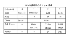
このUSB複合デバイスであるデジタルビデオカメラ102は、CCD201からの画像信号をDV(Digital Video)フォーマット形式でPC100へストリーミング転送する機能を持つデバイスであって、実装するUSBクラスは図3に示す通りである。
The
図3は、本発明の第1乃至3の実施の形態に係るデジタルビデオカメラ102における実装クラスを説明する図である。
Figure 3 is a diagram illustrating the implementation class of the first to the
USBコントローラ212は、通信用に4つのエンドポイント(Endpoints0-3)0〜3(通信用パイプ(Pipe))と、エンドポイント1〜3に対して転送方向及びデータ転送の種別(バルク転送(Bulk)/インタラプト転送(Interrupt)/アイソクロナス転送(Isochronous))を変更する機能を備え、ハイスピード及びフルスピード接続に対応し、USB接続時に、ホストとデバイス間の接続速度モード(ハイスピード/フルスピード)を検知して、CPU208へ接続速度に関する情報を提供できる。また、このデジタルビデオカメラ102の起動時には、図示しないプログラムフラッシュメモリに圧縮されたプログラムは、メモリ209のプログラムエリアに解凍されて展開され、CPU208は、このプログラムエリアに記憶されたプログラムに従って動作するものとする。
The
まず、ハイスピード接続時における動作について説明する。 First, the operation at the time of high speed connection will be described.
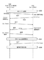
図4は、ハイスピード接続対応のPC100及び、本実施の形態に係るデジタルビデオカメラ102との間のデータ転送動作の流れを示す図である。
FIG. 4 is a diagram showing a flow of data transfer operation between the
USBケーブル101がカメラ102のコネクタ213に接続されると(400)、PC100はUSBケーブル101を通じてデジタルビデオカメラ102に対してVBUSを供給し始める(401)。このVBUSを受け取ったデジタルビデオカメラ102は、PC100との接続を検知し(402)、USBケーブル101のD+信号をプルアップ(Pull up)する(403)。このD+信号のプルアップを受けてデバイスが接続されたことを検知(404)したPC100は、バスリセット(Bus Reset)信号を発し、USBケーブル101のD+信号及びD−信号を一定時間プルダウン(Pull down)する(405)。
When the
このバスリセットを感知したデジタルビデオカメラ102は、このバスリセットが発行されてから所定の時間が経過した後、USBケーブル101のD+信号及びD−信号を使ってハイスピード接続を要求するchirp信号を発行する(406)。PC100は、バスリセットを出力してから所定の時間後、そのバスリセットを解除(オフ)する(407)が、このバスリセットが出力されている期間中にchirp信号を受け取っていた場合には、デジタルビデオカメラ102との接続をハイスピード接続に決定し、以後デジタルビデオカメラ102との通信はハイスピードで行う(408)。
The
こうして速度モードがハイスピードに決定された後、コントロールパイプ(エンドポイント0)により、所定のネゴシエーション動作(409)をPC100及びデジタルビデオカメラ102間で行って論理的な接続を完了する(410)。このネゴシエーション動作については、「Universal Serial Bus Specification2.0」に詳細が記載されているため、ここでは説明を省略する。
After the speed mode is determined to be high speed in this way, a predetermined negotiation operation (409) is performed between the
この論理的接続を確立した後、PC100は不図示のアプリケーション等の要求により、ストリーミング再生を開始する。この場合、PC100はデジタルビデオカメラ102に対してストリーミング再生の開始を示す合図としてコントロールパイプ(エンドポイント0)からSet Interfaceコマンドを発行する(411)。このSet Interfaceコマンドを受けたデジタルビデオカメラ102は、コントロールパイプ(エンドポイント0)からNullパケットを送信する(412)。このNullパケットを受け取ったPC100は、ストリーミング再生用のデータ要求として、アイソクロナスパイプ(エンドポイント2)からIN tokenをデジタルビデオカメラ102へ発行する(413)。これに対してデジタルビデオカメラ102は、DVフォーマット形式のストリーミング用データをアイソクロナスパイプ(エンドポイント2)からPC100へ送出する(414)。これ以後、このIN tokenの発行と、データの送信とを繰り返すことにより、PC100は、DVフォーマット形式でのストリーミング再生を行うことができる。
After establishing this logical connection, the
次に、このストリーミング再生用データの転送中におけるデジタルビデオカメラ102の画像及び音声データの符号化動作について説明する。
Next, the encoding operation of the image and audio data of the
レンズ200により得られた被写体像は、撮像素子201により光電変化され、その変換された電気信号がカメラ信号処理部202へ入力される。カメラ信号処理部202は、この光電変換された電気信号を標準的な画像信号に変換してメモリ209の画像エリアに一時的に格納する。一方、マイク206から得られた音声信号は、音声信号処理部207により標準的な音声信号に変換されて、メモリ209の画像エリアとは別のエリアへ一時的に保存される。画像音声圧縮部205は、メモリ209に一時的に保管された標準的な画像信号及び音声信号をDVフォーマット用に圧縮符号化処理し、メモリ209の別のエリアに一時的に保管する。
The subject image obtained by the
USBコネクタ213にUSBケーブル101が接続されていない場合、或は接続されていても、上述のストリーミング再生が開始されていない場合、表示制御部204はメモリ209に予め用意してあるブルーバック画像用データを表示部203に表示する。これにより表示部203はブルーバック画像を表示する。
If the
ストリーミング再生が開始されている場合、PC100は、USBデバイス102に対してSet Interfaceコマンドを発行した後、IN tokenを発行する。デジタルビデオカメラ102のCPU208は、USBコントローラ212から、このIN tokenを受理すると、DVフォーマットデータをメモリ209からUSBコントローラ212に対して送出する。この際、メモリ209上でヘッダ情報を付加した後、ビデオクラスのパケット化規則に従って送出する。この場合のヘッダ情報の付加及びパケット化については、「Universal Serial Bus Device Class Definition for Video Devices」に規定されているので、その詳細な説明は省略する。
When streaming playback is started, the
また表示制御部204は、上述のように、PC100へのデータ送出が開始されるまでメモリ209に予め用意されているブルーバック画像用データを取得して表示部203に表示しているが、PC10からのSet Interfaceコマンドに対してNull応答し、PC100へのデータ送出が開始されると(414)、CPU208からの指示により表示制御部204は、メモリ209から送出データと同じ画像データを表示部203へ渡して表示する。
Further, as described above, the
以後これらを連続して繰り返すことで、CCD201から入力された画像データとマイク206からの音声データをPC100にストリーミング転送すると共に、転送中の画像データを表示部203に表示できる。
Thereafter, the image data input from the
図5は、本発明の第1の実施の形態に係るデジタルビデオカメラ102におけるハイスピード接続時の処理を説明するフローチャートで、この処理を実行するプログラムはメモリ209のプログラムエリアに記憶されており、CPU208の制御の下に実行される。
FIG. 5 is a flowchart for explaining processing at the time of high-speed connection in the
まずステップS1で、CCD201からの画像信号を入力して、メモリ209の画像エリアに格納し、ステップS2でマイク206からの音声信号を入力してメモリ209の音声エリアに記憶する。そしてステップS3で、これら画像信号と音声信号とを画像音声圧縮部205により圧縮してメモリ209の対応するエリアにそれぞれ記憶する。そしてステップS4で、ストリーミング再生が開始されているかどうかを調べ、開始されていないときはステップS5に進み、表示部203に上述のブルーバック画像の表示を行ってステップS1に戻る。
First, in step S1, an image signal from the
ステップS4で、ストリーミング再生が開始されている場合はステップS6に進み、メモリ209に記憶されているDVフォーマットデータをパケット化し、ステップS7で、PC100に送出する。そしてステップS8で、メモリ209からPC100への送出データと同じ画像データを表示部203に表示してステップS1に戻る。
If streaming playback is started in step S4, the process proceeds to step S6, and the DV format data stored in the
次に、フルスピード接続時における動作について説明する。 Next, the operation at the time of full speed connection will be described.
図6は、ハイスピード接続に対応していないPC100と、本実施の形態に係るデジタルビデオカメラ102との間のデータ転送動作の流れを説明する図である。
FIG. 6 is a diagram for explaining the flow of data transfer operation between the
USBケーブル101がコネクタ213に接続されてPC100とカメラ102とが接続されると(600)、PC100はUSBケーブル101を通じてデジタルビデオカメラ102に対してVBUSを供給し始める(601)。このVBUSを受け取ったデジタルビデオカメラ102はPC100との接続を検知し、USBケーブル101のD+信号をプルアップする(602)。このD+信号のプルアップを受けて、デジタルカメラ102の接続を検知したPC100はバスリセット(Bus Reset)信号を発し(603)、USBケーブル101のD+信号及びD−信号を一定時間プルダウンする。このバスリセットを検知したデジタルビデオカメラ102は、このバスリセットが発行されてから所定の時間が経過した後、USBケーブル101のD+信号及びD−信号を使ってハイスピード接続を要求するchirp信号を発行する(604)。
When the
この場合、PC100はハイスピード接続に対応していないため、バスリセットを発行した後、バスリセットが出力されている期間中にchirp信号が送られてきてもそれを判定できないため、chirp信号を受け取ってから所定時間内にバスリセットを解除できない(605)。これによりデジタルビデオカメラ102は、PC100との接続をフルスピード接続に決定する(606)。こうして接続モードがフルスピード接続に決定されると、デジタルカメラ102のCPU208はUSBコントローラ212を駆動して、USBケーブル101のD+信号とD−信号をプルダウンして(607)、PC100とデジタルカメラ102との間の接続を電気的に切断した状態にする。
In this case, since the
この時、デジタルカメラ102のCPU208は、表示制御部204が表示用の画像データを取り出すメモリ209のエリアに、PC100がストリーミング再生機能をサポートしていないためにフルスピード接続となっていることを示すメッセージ用のデータを書き込む。こうして表示制御部204は、ブルーバック画像用データと、このメッセージとを重ねたデータを表示部203に表示する。このようにしてフルスピード接続時には、ストリーミング再生動作がサポートされないようにする。
At this time, the
このように、第1の実施の形態に係るカメラによれば、ハイスピード接続に対応していない外部機器とUSB接続されているためハイスピード接続が確立できない場合、外部機器との電気的接続を強制的に切断した状態にすることにより、ハイスピード接続以外では実現できない機能の開始を自動的に拒否できる。また、外部機器が対応していないため、その接続を拒否したことをユーザに明示することができる。 As described above, according to the camera of the first embodiment, when the high speed connection cannot be established because the USB connection is established with the external device that does not support the high speed connection, the electrical connection with the external device is established. By forcibly disconnecting, it is possible to automatically reject the start of functions that can only be realized by high-speed connections. Further, since the external device is not compatible, it can be clearly shown to the user that the connection has been refused.
[第2の実施の形態]
前述の第1の実施の形態では、ホスト(PC)とデバイス(デジタルカメラ)との接続を電気的に切断する場合で説明したが、第2の実施の形態では、ストリーミング再生の開始を示す、PC100からのSet Interfaceコマンドに対してStallパケットで応答することによりデータ転送を中止する例で説明する。尚、この第2の実施の形態におけるシステム構成は、前述の第1の実施の形態と同じであり、PC100(ホスト)とデジタルビデオカメラ102(デバイス)間の接続、及びその構成、実装するUSBクラスについては前述の第1の実施の形態と同じであるため、その説明を省略する。
[Second Embodiment]
In the first embodiment described above, the case where the connection between the host (PC) and the device (digital camera) is electrically disconnected has been described, but in the second embodiment, the start of streaming playback is indicated. An example will be described in which data transfer is stopped by responding to the Set Interface command from the
ハイスピード接続時の動作は前述の第1の実施の形態の場合と同じであるため、その説明を省略する。 Since the operation at the time of high-speed connection is the same as that in the first embodiment, the description thereof is omitted.
図7は、本発明の第2の実施の形態に係るフルスピード接続時の動作処理の流れを説明する図で、フルスピード接続の確立(606)までの処理は前述の図6の場合と同じであるため、その説明を省略する。そしてここでは、フルスピード接続の確立(606)後、ネゴシエーションを行って論理的接続を確立する(700)。 FIG. 7 is a diagram for explaining the flow of operation processing at the time of full-speed connection according to the second embodiment of the present invention, and the processing up to the establishment of full-speed connection (606) is the same as the case of FIG. Therefore, the description thereof is omitted. Here, after establishing a full-speed connection (606), negotiation is performed to establish a logical connection (700).
PC100とデジタルカメラ102との間のネゴシエーションにより論理的な接続を確立(700)した後、PC100は、不図示のアプリケーション等の要求により、ストリーミングを開始する場合、PC100はデジタルビデオカメラ102に対しストリーミング再生の開始を示す合図として、コントロールパイプ(エンドポイント0)からSet Interfaceコマンドを発行する(701)。このSet Interfaceコマンドを受けたデジタルビデオカメラ102は、ハイスピード接続が確立されていないため、コントロールパイプ(エンドポイント0)からStallパケットをPC100に送信して(702)、これ以降のデータストリーム再生によるデータ転送を禁止する。このStallパケットを受け取ったPC100は、これ以降、デジタルカメラ102に対して、画像データのデータ転送要求を発行しない。
After establishing a logical connection (700) by negotiation between the
尚、この第2の実施の形態における表示部203への表示は、前述の第1の実施の形態の場合と同じであるため、その説明を省略するが、メッセージの表示タイミングは、Stallパケットによる応答の後とする。
Note that the display on the
このように、第2の実施の形態に係るデジタルビデオカメラによれば、ハイスピード接続に対応していない外部機器とUSB接続されていてハイスピード接続が確立できない場合、ハイスピード接続以外では実現できない機能の開始を自動的に拒否できる。また、その拒否したことをユーザに明示することができる。 Thus, according to the digital video camera according to the second embodiment, when the high-speed connection is the external device USB connection that does not support high-speed connection can not be established, it realized except in high- speed connection Can automatically refuse to start a function that can not be. In addition, the user can be clearly notified of the rejection.
[第3の実施の形態]
前述の第2の実施の形態では、Stallパケットによる応答でデータ転送を中止する例について説明したが、第3の実施の形態では、Nullパケット(空パケット)応答によるデータ転送の中止について説明する。尚、この第3の実施の形態における構成は、前述の第1の実施の形態と同じであり、PC100(ホスト)とデジタルビデオカメラ102(デバイス)間の接続、及びその構成、実装するUSBクラスについては前述の第1の実施の形態と同じである。
[Third Embodiment]
In the above-described second embodiment, an example in which data transfer is stopped by a response by a Stall packet has been described. In the third embodiment, cancellation of data transfer by a Null packet (empty packet) response is described. The configuration of the third embodiment is the same as that of the first embodiment described above. The connection between the PC 100 (host) and the digital video camera 102 (device), the configuration thereof, and the USB class to be mounted Is the same as in the first embodiment.
ハイスピード接続時の動作は第1の実施の形態と同じであるので、その説明を省略する。 Since the operation at the time of high speed connection is the same as that of the first embodiment, the description thereof is omitted.
図8は、本発明の第3の実施の形態に係るフルスピード接続時における動作の流れを説明する図である。図8における論理的接続確立700までの処理は前述の第2の実施の形態(図7)と同じであるため、ここでは説明を省略する。
FIG. 8 is a diagram for explaining the flow of operation during full-speed connection according to the third embodiment of the present invention. The processing up to the
700で論理的な接続を確立した後、PC100は不図示のアプリケーション等の要求により、ストリーミング接続を開始する場合、PC100はデジタルビデオカメラ102に対しストリーミング再生の開始を示す合図として、コントロールパイプ(エンドポイント0)からSet Interfaceコマンドを発行する(801)。このSet Interfaceコマンドを受けたデジタルビデオカメラ102は、Nullパケットにより応答する。そして次にPC100は、デジタルビデオカメラ102に対しストリーミング再生用のデータ転送を要求する合図として、ストリーミング用アイソクロナスパイプ(エンドポイント2)へIN Tokenを発行する(803)。これに対してデジタルビデオカメラ102は、ストリーミング再生用のデータを用意できない合図として、アイソクロナスパイプ(エンドポイント2)からNullパケット(実データなしのパケット)を送出する(804)。以後、このIN tokenの発行と、Nullパケット応答を繰り返し続ける。
After establishing a logical connection in 700, when the
表示部203への表示方法は、前述の第1の第2の実施の形態と同じであるため、その説明を省略するが、表示部203へのメッセージの表示タイミングは、例えば、最初のNullパケット応答(804)後とする。
Since the display method on the
尚、前述の第1乃至第3の実施の形態は、USB接続をビデオクラスの場合で説明したが、本発明はビデオクラスに限ったものではない。 In the first to third embodiments described above, the USB connection has been described for the video class, but the present invention is not limited to the video class.
また、第1乃至第3の実施の形態では、転送用のエンドポイントの種別をアイソクロナス転送としたものとしているが、本発明はアイソクロナス転送に限ったものではない。 In the first to third embodiments, the type of transfer endpoint is assumed to be isochronous transfer, but the present invention is not limited to isochronous transfer.
また、第1乃至第3の実施の形態では、ビデオクラスによる画像及び音声信号を転送する例で説明したが、ビデオクラス以外のクラスによる画像データの転送や、音声データのみの転送等であっても構わない。 In the first to third embodiments, the example of transferring the image and audio signals according to the video class has been described. However, the transfer of image data according to a class other than the video class, the transfer of only audio data, and the like. It doesn't matter.
また、第1乃至第3の実施の形態のビデオクラスに用いる画像符号化フォーマットはDVフォーマットとしているが、本発明はこれに限ったものではない。 The image encoding format used for the video classes of the first to third embodiments is the DV format, but the present invention is not limited to this.
更に、第1乃至第3の実施の形態のストリーム転送用のデータは、その入力をCCD及びマイクとしているが、本発明はこれに限るものではなく、例えばメモリカード等の記憶媒体から読み出して転送する場合にも適用できる。また、第1乃至第3の実施の形態では、非ストリーミング時に表示部に表示される画像をブルーバック画像としているが、ハイスピードモードによるデータ転送ができないことを使用者に認識できる画像であればブルーバック画像以外の画像でもよい。 Furthermore, the data for stream transfer in the first to third embodiments is input to the CCD and the microphone, but the present invention is not limited to this, and is read and transferred from a storage medium such as a memory card, for example. It can also be applied to In the first to third embodiments, the image displayed on the display unit during non-streaming is a blue back image, but any image can be recognized by the user that data transfer in the high speed mode cannot be performed. An image other than the blue back image may be used.
[第4の実施の形態]
前述の第3の実施の形態では、Nullパケット応答によるデータ転送の中止の場合を説明したが、第4の実施の形態ではNack応答によるデータ転送の中止について説明する。尚、この第4の実施の形態におけるシステム構成は、前述の実施の形態と同じであり、PC100(ホスト)とデジタルビデオカメラ102(デバイス)間の接続、及びその構成は前述の実施の形態と同じであるため、その説明を省略する。
[Fourth Embodiment]
In the third embodiment described above, the case of canceling data transfer by a Null packet response has been described. In the fourth embodiment, cancellation of data transfer by a Nack response will be described. The system configuration in the fourth embodiment is the same as that in the previous embodiment, and the connection between the PC 100 (host) and the digital video camera 102 (device) and the configuration thereof are the same as those in the previous embodiment. Since it is the same, the description is omitted.
尚、この第4の実施の形態に係る実装するUSBクラスは図9に示す通りである。 The USB class to be mounted according to the fourth embodiment is as shown in FIG.
図9は、本発明の第4の実施の形態に係るデジタルビデオカメラ102における実装クラスを説明する図である。
FIG. 9 is a diagram for explaining an implementation class in the
図3と比較すると明らかなように、この第4の実施の形態に係るUSBコントローラ212は、通信用に4つのエンドポイント(Endpoints0-3)0〜3(通信用パイプ(Pipe))と、エンドポイント2に対して転送の種別(バルク転送(Bulk))を変更する機能を備え、ハイスピード及びフルスピード接続に対応し、USB接続時に、ホストとデバイス間の接続速度モード(ハイスピード/フルスピード)を検知して、CPU208へ接続速度に関する情報を提供できる。
As is apparent from comparison with FIG. 3, the
次に図10を参照して、ハイスピード接続時における動作について説明する。 Next, the operation at the time of high speed connection will be described with reference to FIG.
図10、本発明の第4の実施の形態に係るハイスピード対応ホスト(PC)100及び、第4の実施の形態に係るデバイス(デジタルビデオカメラ)102との間のデータ転送処理を説明する図である。以下、図10を参照して説明するが、論理的接続確立410までは前述の図4と名時であるため、その説明を省略する。
FIG. 10 is a diagram for explaining data transfer processing between a high-speed compatible host (PC) 100 according to the fourth embodiment of the present invention and a device (digital video camera) 102 according to the fourth embodiment. It is. Hereinafter, description will be made with reference to FIG. 10, but since the
論理的な接続を確立(410)した後、PC100は不図示のアプリケーション等の要求により、ストリーミング再生を開始する場合、PC100はデジタルビデオカメラ102に対して、ストリーミング再生用のデータ受信を示す合図として、ストリーミング再生用バルクパイプ(エンドポイント2)へIN Tokenを発行する(901)。これに対してデジタルビデオカメラ102は、DVフォーマット形式のストリーミング再生用データ(Data)をバルクパイプ(エンドポイント2)からPC100へ送出する(902)。このデータ(Data)を正常に受理できたPC100は、その合図としてデジタルビデオカメラ102に対してAck応答を返す(903)。以後、このIN tokenの発行と、データ(Data)の送信、及びAck応答を繰り返すことにより、DVフォーマット形式でのストリーミング再生が実現できる。
After the logical connection is established (410), when the
この場合の表示部203への表示に関しては、前述の実施の形態と同じであるため、その説明を省略する。
Since the display on the
次にフルスピード接続時における動作について説明するが、論理的接続確立700までは前述の図7及び図8に示す例と同じであるため、ここでは、その説明を省略する。
Next, the operation at the time of full-speed connection will be described, but since the
図11は、本発明の第4の実施の形態に係るフルスピード接続時の動作処理の流れを説明する図で、フルスピード接続の確立(606)後、ネゴシエーションを行って論理的接続を確立する(700)までの処理は前述の実施の形態と同じであるため、その説明を省略する。 FIG. 11 is a diagram for explaining the flow of operation processing at the time of full-speed connection according to the fourth embodiment of the present invention. After establishing (606) the full-speed connection, negotiation is performed to establish a logical connection. Since the processing up to (700) is the same as that of the above-described embodiment, the description thereof is omitted.
PC100とデジタルカメラ102との間のネゴシエーションにより論理的な接続を確立(700)した後、PC100は、不図示のアプリケーション等の要求により、ストリーミング再生を開始する場合、PC100はデジタルビデオカメラ102に対しストリーミング再生の開始を示す合図として、ストリーミング用バルクパイプ(エンドポイント2)へIN Tokenを発行する(910)。このIN Tokenを受けたデジタルビデオカメラ102は、ストリーム再生用のデータを用意できない合図としてバルクパイプ(エンドポイント2)からNackで応答する(911)。そしてこれ以後、このIN tokenの発行と、Nack応答を繰り返す。
After establishing a logical connection (700) by negotiation between the
第4の実施の形態に係る表示部203への表示は、前述の実施の形態の場合と同じであるため、その説明を省略するが、表示部203へのメッセージの表示タイミングは、例えば、最初のNack応答後とする。
Since the display on the
尚、第4の実施の形態は、USB接続をビデオクラスとしたものであるが、ビデオクラスに限ったものではない。また、第4の実施の形態では、ビデオクラスによる画像データ及び音声データの転送の場合で説明したが、ビデオクラス以外のクラスによる画像データの転送や、音声データのみの転送等であっても構わない。 In the fourth embodiment, the USB connection is a video class, but is not limited to the video class. In the fourth embodiment, the case of transferring image data and audio data by a video class has been described. However, transfer of image data by a class other than the video class, transfer of only audio data, or the like may be used. Absent.
また、第4の実施の形態に係るビデオクラスに用いる画像符号化フォーマットはDVフォーマットとしているが、本発明はこれに限ったものではない。 In addition, although the image encoding format used for the video class according to the fourth embodiment is the DV format, the present invention is not limited to this.
また、第4の実施の形態に係るストリーム再生用の転送データは、CCD及びマイクから入力した画像データ及び音声データとしているが本発明はこれに限ったものではない。 The transfer data for stream reproduction according to the fourth embodiment is image data and audio data input from the CCD and microphone, but the present invention is not limited to this.
また、第4の実施の形態では、非ストリーミング時に表示部に表示される画像をブルーバック画像としているが、ハイスピードモードによるデータ転送ができないことを使用者に認識できる画像であればブルーバック画像以外の画像でもよい。 In the fourth embodiment, the image displayed on the display unit during non-streaming is a blue back image. However, if the image can be recognized by the user that data transfer in the high speed mode cannot be performed, the blue back image is displayed. Other images may be used.
また、第4の実施の形態では、ハイスピードモードによるデータ転送ができないことをNack応答によりPC100に通知する構成としたが、これに限るものではない。この構成は、例えば、PC100とデジタルカメラ102との間の接続を電気的に切断する構成に変更することも可能である。
In the fourth embodiment, the
また、第4の実施の形態では、ハイスピードモードによるデータ転送ができないことをNack応答によりPC100に通知する構成としたが、これに限るものではない。この構成は、例えば、Nullパケット応答によりPC100に通知する構成に変更することも可能である。
In the fourth embodiment, the
また、第4の実施の形態では、ハイスピードモードによるデータ転送ができないことをNack応答によりPC100に通知する構成としたが、これに限るものではない。この構成は、例えば、stall応答によりPC100に通知する構成に変更することも可能である。但し、この場合、PC100がSet Interfaceコマンドを送信する構成である必要がある。
In the fourth embodiment, the
以上説明したように、第1乃至第4の実施の形態によれば、ストリーム転送中の画像データを表示部に表示することで、ストリーム再生用データの転送中であるか否かをユーザが判断できる。 As described above, according to the first to fourth embodiments, the user determines whether or not the stream reproduction data is being transferred by displaying the image data being stream transferred on the display unit. it can.
また、第1乃至第4の実施の形態によれば、PCなどの外部機器でストリーミング再生の開始を指示したにも拘わらずストリーム再生を実行できない場合、その旨をユーザに報知できる。 In addition, according to the first to fourth embodiments, when stream playback cannot be executed even though an external device such as a PC is instructed to start streaming playback, the user can be notified of this.
[他の実施の形態]
本発明の目的は前述したように、実施形態の機能を実現するソフトウェアのプログラムコードを記録した記憶媒体をシステム或は装置に提供し、そのシステム或は装置のコンピュータ(又はCPUやMPU)が記憶媒体に格納されたプログラムコードを読み出し実行することによっても達成される。この場合、記憶媒体から読み出されたプログラムコード自体が前述した実施形態の機能を実現することになり、そのプログラムコードを記憶した記憶媒体は本発明を構成することになる。このようなプログラムコードを供給するための記憶媒体としては、例えば、フロッピィ(登録商標)ディスク、ハードディスク、光ディスク、光磁気ディスク、CD−ROM,CD−R、磁気テープ、不揮発性のメモリカード、ROMなどを用いることができる。
[Other embodiments]
As described above, the object of the present invention is to provide a system or apparatus with a storage medium storing software program codes for realizing the functions of the embodiment, and the computer of the system or apparatus (or CPU or MPU) stores it. It is also achieved by reading and executing the program code stored on the medium. In this case, the program code itself read from the storage medium realizes the functions of the above-described embodiments, and the storage medium storing the program code constitutes the present invention. As a storage medium for supplying such a program code, for example, a floppy (registered trademark) disk, hard disk, optical disk, magneto-optical disk, CD-ROM, CD-R, magnetic tape, nonvolatile memory card, ROM Etc. can be used.
また、コンピュータが読み出したプログラムコードを実行することにより、前述した実施の形態の機能が実現されるだけでなく、そのプログラムコードの指示に基づき、コンピュータ上で稼動しているOS(オペレーティングシステム)などが実際の処理の一部又は全部を行い、その処理によって前述した実施の形態の機能が実現される場合も含まれている。 Further, by executing the program code read by the computer, not only the functions of the above-described embodiments are realized, but also an OS (operating system) running on the computer based on the instruction of the program code Includes a case where the function of the above-described embodiment is realized by performing part or all of the actual processing.
更に、記憶媒体から読み出されたプログラムコードが、コンピュータに挿入された機能拡張ボードやコンピュータに接続された機能拡張ユニットに備わるメモリに書きこまれた後、そのプログラムコードの指示に基づき、その機能拡張ボードや機能拡張ユニットに備わるCPUなどが実際の処理の一部又は全部を行い、その処理によって前述した実施の形態の機能が実現される場合も含む。 Furthermore, after the program code read from the storage medium is written in the memory provided in the function expansion board inserted into the computer or the function expansion unit connected to the computer, the function is determined based on the instruction of the program code. This includes the case where the CPU of the expansion board or function expansion unit performs part or all of the actual processing, and the functions of the above-described embodiments are realized by the processing.
Claims (8)
前記外部装置との間の接続がハイスピード接続でなくフルスピード接続である場合は、前記外部装置との間の接続を電気的に切断しないようにするとともに、前記外部装置からSet Interfaceコマンドを受信したか否かを判定する制御手段を有し、When the connection with the external device is not a high speed connection but a full speed connection, the connection with the external device is not electrically disconnected and the Set Interface command is received from the external device. Control means for determining whether or not
前記外部装置との間の接続が前記ハイスピード接続でなく前記フルスピード接続である場合に、前記外部装置から前記Set Interfaceコマンドを受信したときは、前記制御手段は、前記ハイスピード接続では実現できるが前記フルスピード接続では実現できない機能が実行されないようにするために、Stallパケットを前記外部装置に送信し、前記機能が無効であることを示す情報を表示手段に表示するように制御することを特徴とする電子機器。When the connection with the external device is not the high-speed connection but the full-speed connection, when the Set Interface command is received from the external device, the control means can be realized by the high-speed connection. In order to prevent functions that cannot be realized by the full-speed connection from being executed, control is performed so that a Stall packet is transmitted to the external device and information indicating that the function is invalid is displayed on the display means. Features electronic equipment.
前記外部装置との間の接続がハイスピード接続でなくフルスピード接続である場合は、前記外部装置との間の接続を電気的に切断しないようにするとともに、前記外部装置からSet Interfaceコマンドを受信したか否かを判定する制御手段を有し、When the connection with the external device is not a high speed connection but a full speed connection, the connection with the external device is not electrically disconnected and the Set Interface command is received from the external device. Control means for determining whether or not
前記外部装置との間の接続が前記ハイスピード接続でなく前記フルスピード接続である場合に、前記外部装置から前記Set Interfaceコマンドを受信したときは、前記制御手段は、前記ハイスピード接続では実現できるが前記フルスピード接続では実現できない機能が実行されないようにするために、Nullパケットを前記外部装置に送信し、前記機能が無効であることを示す情報を表示手段に表示するように制御することを特徴とする電子機器。When the connection with the external device is not the high-speed connection but the full-speed connection, when the Set Interface command is received from the external device, the control means can be realized by the high-speed connection. In order to prevent a function that cannot be realized by the full-speed connection from being executed, control is performed so that a null packet is transmitted to the external device and information indicating that the function is invalid is displayed on the display unit. Features electronic equipment.
前記外部装置との間の接続がハイスピード接続でなくフルスピード接続である場合は、前記外部装置との間の接続を電気的に切断しないようにするとともに、前記外部装置からSet Interfaceコマンドを受信したか否かを判定する制御手段を有し、When the connection with the external device is not a high speed connection but a full speed connection, the connection with the external device is not electrically disconnected and the Set Interface command is received from the external device. Control means for determining whether or not
前記外部装置との間の接続が前記ハイスピード接続でなく前記フルスピード接続である場合に、前記外部装置から前記Set Interfaceコマンドを受信したときは、前記制御手段は、前記ハイスピード接続では実現できるが前記フルスピード接続では実現できない機能が実行されないようにするために、Nackを前記外部装置に送信し、前記機能が無効であることを示す情報を表示手段に表示するように制御することを特徴とする電子機器。When the connection with the external device is not the high-speed connection but the full-speed connection, when the Set Interface command is received from the external device, the control means can be realized by the high-speed connection. In order to prevent functions that cannot be realized by the full-speed connection from being executed, control is performed so that Nack is transmitted to the external device and information indicating that the function is invalid is displayed on the display unit Electronic equipment.
Priority Applications (2)
| Application Number | Priority Date | Filing Date | Title |
|---|---|---|---|
| JP2004162463A JP4750379B2 (en) | 2004-05-31 | 2004-05-31 | Electronics |
| US11/142,162 US7676612B2 (en) | 2004-05-31 | 2005-05-31 | Video camera device and control method thereof |
Applications Claiming Priority (1)
| Application Number | Priority Date | Filing Date | Title |
|---|---|---|---|
| JP2004162463A JP4750379B2 (en) | 2004-05-31 | 2004-05-31 | Electronics |
Publications (3)
| Publication Number | Publication Date |
|---|---|
| JP2005346209A JP2005346209A (en) | 2005-12-15 |
| JP2005346209A5 JP2005346209A5 (en) | 2007-07-19 |
| JP4750379B2 true JP4750379B2 (en) | 2011-08-17 |
Family
ID=35425024
Family Applications (1)
| Application Number | Title | Priority Date | Filing Date |
|---|---|---|---|
| JP2004162463A Expired - Fee Related JP4750379B2 (en) | 2004-05-31 | 2004-05-31 | Electronics |
Country Status (2)
| Country | Link |
|---|---|
| US (1) | US7676612B2 (en) |
| JP (1) | JP4750379B2 (en) |
Families Citing this family (10)
| Publication number | Priority date | Publication date | Assignee | Title |
|---|---|---|---|---|
| JP2005071273A (en) * | 2003-08-27 | 2005-03-17 | Canon Inc | Electronic device and method of controlling interface thereof |
| EP1798964A1 (en) * | 2005-12-16 | 2007-06-20 | STMicroelectronics (Research & Development) Limited | Image sensor coprocessor |
| JP2007178648A (en) * | 2005-12-27 | 2007-07-12 | Kenwood Corp | Onboard reproducing device |
| US7893990B1 (en) | 2006-07-31 | 2011-02-22 | Cisco Technology, Inc. | Digital video camera with retractable data connector and resident software application |
| US8223262B2 (en) * | 2007-10-26 | 2012-07-17 | Cisco Technology, Inc. | Charging and use scheme for a hand-held electronics device |
| JP2010212947A (en) * | 2009-03-10 | 2010-09-24 | Sony Corp | Information processing device and method, information processing system, and program |
| USD627380S1 (en) | 2009-10-08 | 2010-11-16 | Cisco Technology, Inc. | Digital video camera with a connector |
| JP5700514B2 (en) * | 2010-10-27 | 2015-04-15 | アルパイン株式会社 | Communication speed control device and communication speed control method |
| TWI567633B (en) * | 2015-07-07 | 2017-01-21 | 鈺群科技股份有限公司 | Activation method of a universal serial bus compatible flash device and related universal serial bus compatible flash device |
| WO2018008109A1 (en) * | 2016-07-06 | 2018-01-11 | Eizo株式会社 | Usb device |
Family Cites Families (41)
| Publication number | Priority date | Publication date | Assignee | Title |
|---|---|---|---|---|
| JPH10136245A (en) | 1996-10-25 | 1998-05-22 | Sharp Corp | Camera device system |
| US6012103A (en) | 1997-07-02 | 2000-01-04 | Cypress Semiconductor Corp. | Bus interface system and method |
| US5974486A (en) | 1997-08-12 | 1999-10-26 | Atmel Corporation | Universal serial bus device controller comprising a FIFO associated with a plurality of endpoints and a memory for storing an identifier of a current endpoint |
| TW455805B (en) * | 1998-02-26 | 2001-09-21 | Winbond Electronics Corp | Converter allowing data communications equipment to transmit data to data terminal equipment through universal serial bus and the control method thereof |
| JPH11250009A (en) | 1998-03-04 | 1999-09-17 | Uniden Corp | Server device and web data converting system |
| JP3711432B2 (en) | 1998-04-15 | 2005-11-02 | セイコーエプソン株式会社 | Peripheral processing apparatus and control method thereof |
| US6731650B1 (en) * | 1998-04-27 | 2004-05-04 | Canon Kabushiki Kaisha | Data transfer apparatus and its control method |
| US6359951B1 (en) * | 1998-06-03 | 2002-03-19 | Intel Corporation | Method and apparatus for high speed signaling |
| US6108028A (en) * | 1998-11-02 | 2000-08-22 | Intel Corporation | Method of activating and deactivating a screen saver in a video conferencing system |
| JP2000194645A (en) | 1998-12-28 | 2000-07-14 | Toshiba Corp | Electronic device and its control method and device |
| US6801576B1 (en) * | 1999-08-06 | 2004-10-05 | Loudeye Corp. | System for accessing, distributing and maintaining video content over public and private internet protocol networks |
| WO2001048613A2 (en) * | 1999-12-24 | 2001-07-05 | Koninklijke Philips Electronics N.V. | Emulation of a disconnect of a device |
| US6697884B1 (en) * | 2000-01-03 | 2004-02-24 | Genesis Microchip, Inc. | Communication protocol for serial peripheral devices |
| US6542946B1 (en) * | 2000-01-28 | 2003-04-01 | Compaq Information Technologies Group, L.P. | Dual mode differential transceiver for a universal serial bus |
| JP2001222503A (en) | 2000-02-08 | 2001-08-17 | Ricoh Co Ltd | Peripheral equipment control system |
| JP2001256183A (en) | 2000-03-13 | 2001-09-21 | Keitaro Aso | Homepage preparation method using internet and server |
| JP3603732B2 (en) * | 2000-03-16 | 2004-12-22 | セイコーエプソン株式会社 | Data transfer control device and electronic equipment |
| JP3415567B2 (en) * | 2000-06-21 | 2003-06-09 | エヌイーシーマイクロシステム株式会社 | USB transfer control method and USB controller |
| JP2002077182A (en) * | 2000-08-29 | 2002-03-15 | Sony Corp | Network error display device and error detection display method |
| JP4124990B2 (en) * | 2000-11-07 | 2008-07-23 | キヤノン株式会社 | IMAGING DEVICE AND IMAGING DEVICE CONTROL METHOD |
| JP2002223213A (en) | 2001-01-26 | 2002-08-09 | Matsushita Electric Ind Co Ltd | Method of transferring data, storage device, method of controlling the same, and data transfer controller |
| US7656426B2 (en) * | 2001-04-06 | 2010-02-02 | Sony Corporation | Digital camera and data transfer method from a record medium |
| JP2002312081A (en) | 2001-04-13 | 2002-10-25 | Sanyo Electric Co Ltd | Interface circuit and disk drive device |
| JP2002318778A (en) | 2001-04-20 | 2002-10-31 | Ricoh Co Ltd | Data communication system and data communication method |
| JP2002342260A (en) | 2001-05-22 | 2002-11-29 | Nec Microsystems Ltd | Usb transmission control circuit and control method therefor |
| US6775733B2 (en) * | 2001-06-04 | 2004-08-10 | Winbond Electronics Corp. | Interface for USB host controller and root hub |
| US20030007001A1 (en) * | 2001-06-07 | 2003-01-09 | Philips Electronics North America Corporation | Automatic setting of video and audio settings for media output devices |
| JP2003050767A (en) | 2001-08-07 | 2003-02-21 | Sony Corp | System, method for distributing information, device and method for supplying information |
| US7043587B2 (en) * | 2001-09-20 | 2006-05-09 | Lenovo (Singapore) Pte. Ltd. | System and method for connecting a universal serial bus device to a host computer system |
| JP2003131865A (en) | 2001-10-22 | 2003-05-09 | Sony Corp | Display device and display method, display control device and display control method, display system, and program |
| JP2003150539A (en) | 2001-11-15 | 2003-05-23 | Canon Inc | Peripheral equipment, control device of peripheral equipment, system and control method |
| US6573846B1 (en) * | 2001-12-31 | 2003-06-03 | Apple Computer, Inc. | Method and apparatus for variable length decoding and encoding of video streams |
| US7272740B2 (en) * | 2002-01-04 | 2007-09-18 | Agere Systems Inc. | Performance indication system for use with a universal serial bus signal and a method of operation thereof |
| CN1180354C (en) | 2002-01-28 | 2004-12-15 | 威盛电子股份有限公司 | USB control circuit capable of switching path automatically |
| US7545434B2 (en) * | 2002-02-04 | 2009-06-09 | Hewlett-Packard Development Company, L.P. | Video camera with variable image capture rate and related methodology |
| KR20030072980A (en) | 2002-03-07 | 2003-09-19 | 기가시스네트(주) | The method and equipment for USB Host/Client mode detection and changing |
| JP2003281088A (en) | 2002-03-20 | 2003-10-03 | Seiko Epson Corp | Method for evaluating recorder mounted with usb interface and usb interface control program for evaluating recorder |
| KR100919978B1 (en) * | 2002-09-26 | 2009-10-05 | 삼성디지털이미징 주식회사 | Digital camera which displays communication state, and control method thereof |
| US6842058B2 (en) * | 2002-11-12 | 2005-01-11 | Lsi Logic Corporation | Method and apparatus for slew control of an output signal |
| KR100920664B1 (en) | 2002-11-19 | 2009-10-09 | 엘지전자 주식회사 | Apparatus and method for driving system in personal digital assistant |
| JP2005071273A (en) * | 2003-08-27 | 2005-03-17 | Canon Inc | Electronic device and method of controlling interface thereof |
-
2004
- 2004-05-31 JP JP2004162463A patent/JP4750379B2/en not_active Expired - Fee Related
-
2005
- 2005-05-31 US US11/142,162 patent/US7676612B2/en not_active Expired - Fee Related
Also Published As
| Publication number | Publication date |
|---|---|
| US7676612B2 (en) | 2010-03-09 |
| JP2005346209A (en) | 2005-12-15 |
| US20050265099A1 (en) | 2005-12-01 |
Similar Documents
| Publication | Publication Date | Title |
|---|---|---|
| JP4829806B2 (en) | Data processing apparatus and computer program | |
| US7676612B2 (en) | Video camera device and control method thereof | |
| US8612653B2 (en) | Information processing apparatus and method, and computer program therefor | |
| WO2009147839A1 (en) | Communication device and conversion adapter | |
| EP1793315B1 (en) | Combination apparatus capable of data communication between host devices and method thereof | |
| JP5344542B2 (en) | Communication device | |
| JP4976654B2 (en) | Communication apparatus and computer program | |
| US20080292280A1 (en) | Recording apparatus and recording method | |
| JP2005071273A (en) | Electronic device and method of controlling interface thereof | |
| EP1227486A2 (en) | Recording and playback apparatus and method, program storage medium, and program | |
| JP2010278969A (en) | Communication device and control method | |
| JP4695965B2 (en) | Video recording apparatus and program | |
| JP2005328280A (en) | Data processor | |
| JP2006245796A (en) | Image supply apparatus, information processing apparatus, and control method thereof | |
| KR101115942B1 (en) | Apparatus and method for processing thumbnail image in television receiver | |
| JP2007088592A (en) | Video imaging and recording apparatus | |
| JP4537169B2 (en) | Host device and control method thereof | |
| JP2005354639A (en) | Communication apparatus, imaging apparatus, and network system | |
| JP2002064511A (en) | Data communication system, electronic device and method for controlling them | |
| JP2006163906A (en) | Data processing device, data processing method, and program | |
| JP2006113766A (en) | Video device and video output control method | |
| JP3985010B2 (en) | Data communication device | |
| JP2011142618A (en) | Imaging device, electronic apparatus, data processing system, and computer program | |
| JP2005176249A (en) | Control apparatus, control method, control system, and control program | |
| JP2006191171A (en) | Control unit, control method, and program |
Legal Events
| Date | Code | Title | Description |
|---|---|---|---|
| A521 | Request for written amendment filed |
Free format text: JAPANESE INTERMEDIATE CODE: A523 Effective date: 20070531 |
|
| A621 | Written request for application examination |
Free format text: JAPANESE INTERMEDIATE CODE: A621 Effective date: 20070531 |
|
| RD03 | Notification of appointment of power of attorney |
Free format text: JAPANESE INTERMEDIATE CODE: A7423 Effective date: 20070531 |
|
| A977 | Report on retrieval |
Free format text: JAPANESE INTERMEDIATE CODE: A971007 Effective date: 20090105 |
|
| A131 | Notification of reasons for refusal |
Free format text: JAPANESE INTERMEDIATE CODE: A131 Effective date: 20090113 |
|
| A521 | Request for written amendment filed |
Free format text: JAPANESE INTERMEDIATE CODE: A523 Effective date: 20090316 |
|
| A02 | Decision of refusal |
Free format text: JAPANESE INTERMEDIATE CODE: A02 Effective date: 20091009 |
|
| A01 | Written decision to grant a patent or to grant a registration (utility model) |
Free format text: JAPANESE INTERMEDIATE CODE: A01 |
|
| A61 | First payment of annual fees (during grant procedure) |
Free format text: JAPANESE INTERMEDIATE CODE: A61 Effective date: 20110519 |
|
| R150 | Certificate of patent or registration of utility model |
Free format text: JAPANESE INTERMEDIATE CODE: R150 Ref document number: 4750379 Country of ref document: JP Free format text: JAPANESE INTERMEDIATE CODE: R150 |
|
| FPAY | Renewal fee payment (event date is renewal date of database) |
Free format text: PAYMENT UNTIL: 20140527 Year of fee payment: 3 |
|
| LAPS | Cancellation because of no payment of annual fees |