JP4740539B2 - Method and system for removing contouring artifacts - Google Patents
Method and system for removing contouring artifacts Download PDFInfo
- Publication number
- JP4740539B2 JP4740539B2 JP2003564810A JP2003564810A JP4740539B2 JP 4740539 B2 JP4740539 B2 JP 4740539B2 JP 2003564810 A JP2003564810 A JP 2003564810A JP 2003564810 A JP2003564810 A JP 2003564810A JP 4740539 B2 JP4740539 B2 JP 4740539B2
- Authority
- JP
- Japan
- Prior art keywords
- pixel
- range
- identified
- pixels
- calculating
- Prior art date
- Legal status (The legal status is an assumption and is not a legal conclusion. Google has not performed a legal analysis and makes no representation as to the accuracy of the status listed.)
- Expired - Fee Related
Links
- 238000000034 method Methods 0.000 title claims description 42
- 238000012545 processing Methods 0.000 claims description 7
- 230000008569 process Effects 0.000 description 27
- 238000001514 detection method Methods 0.000 description 9
- 238000012360 testing method Methods 0.000 description 9
- 230000008859 change Effects 0.000 description 4
- 238000012935 Averaging Methods 0.000 description 3
- 238000013139 quantization Methods 0.000 description 3
- 238000004891 communication Methods 0.000 description 2
- 238000010586 diagram Methods 0.000 description 2
- 238000011156 evaluation Methods 0.000 description 2
- 230000000007 visual effect Effects 0.000 description 2
- 238000006243 chemical reaction Methods 0.000 description 1
- 230000006835 compression Effects 0.000 description 1
- 238000007906 compression Methods 0.000 description 1
- 238000012937 correction Methods 0.000 description 1
- 230000000694 effects Effects 0.000 description 1
- 238000012986 modification Methods 0.000 description 1
- 230000004048 modification Effects 0.000 description 1
- 230000004044 response Effects 0.000 description 1
- 230000001360 synchronised effect Effects 0.000 description 1
Images


Classifications
-
- G06T5/70—
-
- G—PHYSICS
- G06—COMPUTING; CALCULATING OR COUNTING
- G06V—IMAGE OR VIDEO RECOGNITION OR UNDERSTANDING
- G06V10/00—Arrangements for image or video recognition or understanding
- G06V10/20—Image preprocessing
- G06V10/30—Noise filtering
-
- G—PHYSICS
- G06—COMPUTING; CALCULATING OR COUNTING
- G06V—IMAGE OR VIDEO RECOGNITION OR UNDERSTANDING
- G06V10/00—Arrangements for image or video recognition or understanding
- G06V10/20—Image preprocessing
- G06V10/34—Smoothing or thinning of the pattern; Morphological operations; Skeletonisation
-
- G—PHYSICS
- G06—COMPUTING; CALCULATING OR COUNTING
- G06T—IMAGE DATA PROCESSING OR GENERATION, IN GENERAL
- G06T2207/00—Indexing scheme for image analysis or image enhancement
- G06T2207/10—Image acquisition modality
- G06T2207/10016—Video; Image sequence
Description
本発明は、画像表示システムの分野に関し、特に、画像表示システムに生じるコンタリング(contouring:擬似輪郭、偽輪郭)アーティファクト(artifact)を除去する方法とシステムに関する。 The present invention relates to the field of image display systems, and more particularly to a method and system for removing contouring artifacts that occur in image display systems.
従来のディジタル・ビデオ信号は全て、種々のビデオ処理の段階で量子化される。例えば、アナログ/ディジタル変換や或る種の圧縮技術は、量子化を伴う。量子化の1つの欠点として、輝度勾配の低い画像部分で、コンタリング(擬似輪郭、偽輪郭)として知られる視覚上のアーティファクトを起こす傾向がある。コンタリングが起こると、画像信号の量子化により、入力画像中には存在しない輪郭が出力信号中に現れる。具体的に言うと、入力信号を量子化する際、ゆるやかな画像勾配は、画素の隣接する幾つかの大きなブロックに変形される。1ブロック内の各画素には同一の画像信号値が割り当てられている。これらの大きな隣接画素のブロックが、均質でない画素の区域により分離されなければ、これらのブロックは、「階段(stair step)」効果を起こし、元の画像の滑らかな曲線は、一連の単色の平坦な面に見える。コンタリングは、輝度の空間的変化の少ない画像部分の僅かな変化を感知できる人間の視覚能力と関係がある。このような画像部分の輝度を表すビット数が不十分であれば、人間の視覚はこの輝度変化を、つながりのある連続的状態として感知せず、階段(ステップ)状のものとして感知する。本発明は、この欠点の解決に向けられている。 All conventional digital video signals are quantized at various stages of video processing. For example, analog / digital conversion and some compression techniques involve quantization. One drawback of quantization is that it tends to cause visual artifacts known as contouring (pseudo contours, false contours) in image portions with low brightness gradients. When contouring occurs, contours that do not exist in the input image appear in the output signal due to quantization of the image signal. Specifically, when the input signal is quantized, the gradual image gradient is transformed into several large blocks of adjacent pixels. The same image signal value is assigned to each pixel in one block. If these large blocks of adjacent pixels are not separated by areas of non-homogeneous pixels, these blocks will have a “stair step” effect, and the smooth curve of the original image will be a series of monochromatic flats. It looks like a nice face. Contouring is related to the human visual ability that can perceive slight changes in image portions with little spatial variation in brightness. If the number of bits representing the brightness of such an image portion is insufficient, human vision does not perceive this change in brightness as a connected continuous state, but as a staircase (step). The present invention is directed to overcoming this drawback.
(発明の概要)
簡単に言えば、本発明は受信したビデオ信号におけるアーティファクトであるコンタリングを検出し、検出されたアーティファクトを除去する。ディザ処理(dithering:ディザリング)により、ビデオ信号中の選択された画素に最下位ビットを加えることにより、或いは未使用の状態を利用することにより、この検出されたアーティファクトを除去する。
(Summary of Invention)
In brief, the present invention detects contouring, which is an artifact in the received video signal, and removes the detected artifact. Dithering removes this detected artifact by adding the least significant bit to the selected pixel in the video signal or by utilizing an unused state.
本発明の特性と利点は、以下の説明から、より一層明らかとなる。 The characteristics and advantages of the present invention will become more apparent from the following description.
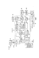
図1に、本発明により動作するディジタル・ビデオ信号受信システムをブロック図で例示する。ビデオ受信システムは、オーディオ/ビデオ/関連データを搬送する信号で変調された放送搬送波を受信してディジタル化するためのアンテナ10と入力プロセッサ15、入力プロセッサ15からのディジタル出力信号を受信/復調する復調器20、およびトレリス(trellis)復号化され、バイト長のデータ・セグメントにマップされ、デインタリーブされ、そしてリード・ソロモン(RS:Reed‐Solomon)誤り訂正される信号を出力するデコーダ30を具える。デコーダ30からの訂正された出力データは、MPEGと互換性のあるトランスポート・データ・ストリームの形式をとり、プログラム(番組)を表す多重化されたオーディオ/ビデオ/データ成分を含んでいる。
FIG. 1 is a block diagram illustrating a digital video signal receiving system that operates in accordance with the present invention. The video receiving system receives / demodulates an
更に、ビデオ受信システムは、電話線を介してサーバ83または接続サービス87に接続されるモデム80を具え、データを種々のフォーマット(MPEG、HTML、JAVA(登録商標)など)で電話線を介してビデオ受信システムで受信することができる。
Further, the video receiving system includes a
プロセッサ25は、デコーダ30またはモデム80から出力されるデータを処理し、処理されたデータは、利用者がリモコン125で入力するリクエスト(要求)により、ディスプレイ装置75に表示され、または記憶メディア(媒体)105に記憶される。更に、プロセッサ25は、コントローラ115を具える。コントローラ115は、リモコン125からリモート・ユニット・インタフェース120を介して受信されるリクエストを解釈し、プロセッサ25の各要素を適正に制御し、利用者のリクエスト(例えば、チャンネル、ウェブサイト、またはオンスクリーン表示(OSD))を実行する。1つの例示的モードで、コントローラ115は、プロセッサ25の各要素を制御し、MPEG復号化データ、およびディスプレイ75に表示するオンスクリーン表示(OSD)を供給する。別のモードにおいて、コントローラ115は、プロセッサ25の各要素を制御し、記憶装置90と記憶インタフェース95を介して記憶媒体105に記憶されるMPEGと互換性のあるデータ・ストリームを供給する。更なる例示的モードで、コントローラ115は、サーバ83または接続サービス87を介する双方向の(例えば、インターネット)通信を受信するような、他の通信モードのためにプロセッサ25の各要素を制御する。
The
プロセッサ25は、トランスポート・ストリーム内の選択されたパケットを識別してそれをデコーダ30からトランスポート・デコーダ55に送るPID選択装置45を含んでいる。デコーダ30からのトランスポート・ストリームは、トランスポート・デコーダ55により、オーディオ/ビデオ/データ成分にデマルチプレクス(逆多重化)され、以下に詳細に述べるように、プロセッサ25の他の要素により更に処理される。
The
プロセッサ25に供給されるトランスポート・ストリームは、番組チャンネル・データ、補助的システム・タイミング情報、および番組特定情報(番組内容の評価、番組のアスペクト(縦横)比、および番組ガイド情報のような)を含んでいるデータ・パケットから成る。トランスポート・デコーダ55は、補助情報パケットをコントローラ115に導き、コントローラ115は、補助情報を解析(parse:パース)し、照合(collate:コレート)し、そして階層構造のテーブルの中に組立てる(assemble:アセンブル)。ユーザが、選択した番組チャンネルを含む個々のデータ・パケットは、収集された番組特定情報を使用して、識別/収集される。システム・タイミング情報には、タイム・リファレンス・インディケータ(指標)および関連する訂正データ(例えば、夏時間(サマータイム)指標、およびタイム・ドリフト(時間変動)/閏年などを調節するオフセット情報)が含まれる。タイミング情報は、将来の番組の放送日時を設定するために、デコーダがタイム・リファレンス・インディケータをタイム・クロック(例えば、米国東海岸の日付と時刻)に変換するのに役立つ。このタイム・クロックは、予定される番組を処理する機能(例えば、番組の放送、番組の録画、番組の再生)を開始させるのに使用できる。番組特定情報には、条件付きアクセス(CA:コンディショナル・アクセス)、ネットワーク情報、および希望するチャンネルにシステム(図1)が同調しデータ・パケットを収集して完全な番組を形成できるようにする識別/連結(リンク)データが含まれる。
The transport stream supplied to the
トランスポート・デコーダ55は、MPEGと互換性のあるビデオ/オーディオ/サブピクチャ(sub−picture:副画像)ストリームをMPEGデコーダ65に供給する。このビデオ/オーディオ・ストリームには、選択されたチャンネルの番組内容を表す、圧縮されたビデオ/オーディオ・データが含まれる。サブピクチャ・データには、そのチャンネルの番組内容(例えば、評価情報、番組説明情報など)が含まれる。
The
MPEGデコーダ65は、ランダム・アクセス・メモリ(RAM)67と協働して、ユニット55(トランスポート・デコーダ)からのMPEGと互換性のあるパケット化されたオーディオ/ビデオ・データを復号化し、圧縮解除(decompress:デコンプレス、解凍)し、圧縮解除された番組を表す画素データをディスプレイ・プロセッサ70に供給する。デコーダ65は、ユニット55からのサブピクチャ・データを組立て、照合し、解釈して、フォーマット化された番組ガイド・データを発生して、内部のオンスクリーン表示(OSD)モジュール(図示せず)に出力する。OSDモジュールは、RAM67と協働し、サブピクチャ・データおよび他の情報を処理し、サブタイトル(字幕)/コントロール/情報メニュー(ディスプレイ75に表示する、選択可能なメニュー・オプションおよび他の項目を含む)を表すマップ化画素(pixel mapped)データを発生する。表示されるコントロール/情報メニューにより、ユーザは、視聴する番組を選択し、そして将来の番組を処理する機能(視聴用に選択した番組を受信するための同調、記憶媒体105への番組の録画、および記憶媒体105からの番組の再生)をスケジュールする。
The MPEG
オンスクリーン表示(OSD)モジュール(図示せず)で発生されるテキスト(文字)とグラフィックス(図形)を含む、コントロール(制御)/情報の表示は、コントローラ115の制御の下で、オーバレイ(overlay)マップ化画素データの形式で発生される。OSDモジュールからのオーバレイマップ化画素データは、コントローラ115の制御の下で、MPEGデコーダ65からの圧縮解除された画素を表すデータと合成され、同期される。選択されたチャンネルのビデオ番組を表す合成されたマップ化画素データは、関連するサブピクチャ・データと共に、ディスプレイ・プロセッサ70で符号化され、ディスプレイ75に出力され表示される。
The display of controls / information, including text (characters) and graphics (graphics) generated in an on-screen display (OSD) module (not shown), can be overlaid under the control of the controller 115. ) Generated in the form of mapped pixel data. The overlay mapped pixel data from the OSD module is synthesized and synchronized with data representing the decompressed pixels from the
本発明の原理は、地上/ケーブル/衛星/DSL/インターネットまたはコンピュータ・ネットワーク放送システム(符号化のタイプまたは変調形式を変更可能な)に応用される。このようなシステムには、他のタイプの符号化データ・ストリーム、および番組特定情報を伝送する他の方法を使用する、MPEGと非互換性のシステムも含まれる。開示されたこのシステムは、放送番組を処理するものとして説明されているが、これは例示的なものにすぎない。図1のアーキテクチャは、他を排除するものではない。同じ目的を達成するために、本発明の原理に従って、他のアーキテクチャも派生される。 The principles of the present invention apply to terrestrial / cable / satellite / DSL / Internet or computer network broadcast systems (which can change the type of encoding or modulation format). Such systems also include systems that are incompatible with MPEG that use other types of encoded data streams and other methods of transmitting program specific information. Although the disclosed system has been described as processing broadcast programs, this is merely exemplary. The architecture of FIG. 1 does not exclude others. Other architectures are derived in accordance with the principles of the present invention to accomplish the same purpose.
図2〜図6は、本発明のコンタリング検出/除去プロセスを説明する。所定の画素範囲(例えば、一次元の水平/垂直画素範囲、二次元の方形画素範囲または円形画素範囲のような多次元の画素範囲、或いは当業者に知られる他の画素範囲)の成分値(例えば、赤(R)、緑(G)、青(B)の成分値)に、各画素毎に、本発明のプロセスが適用され、ディスプレイ・プロセッサ70(図1)のプログラムによる命令で、全体または一部として、実行される。或いは、本発明のプロセスは、コンタリング検出/除去回路(図示せず)としてハードウェアでも実施できる。 2-6 illustrate the contouring detection / removal process of the present invention. Component values (for example, one-dimensional horizontal / vertical pixel ranges, two-dimensional square pixel ranges or multi-dimensional pixel ranges such as circular pixel ranges, or other pixel ranges known to those skilled in the art) For example, the process of the present invention is applied to each pixel for red (R), green (G), and blue (B) component values, and the entire process is executed by an instruction by the program of the display processor 70 (FIG. 1). Or as part. Alternatively, the process of the present invention can be implemented in hardware as a contouring detection / removal circuit (not shown).
図2に、本発明の好ましいコンタリング検出プロセス200を示す。スタート(開始)のステップ205で、ディスプレイ・プロセッサ70は、所定の画素成分値の範囲(例えば、8画素の範囲)を識別する。所定の画素範囲(span:スパン)が識別されると、ステップ210で、プロセッサ70は、この所定の画素範囲内で最大と最小の画素成分値を決定する。次に、ステップ215で、プロセッサ70は、最大成分値−(マイナス)最小成分値が、所定の閾値「N」以下であるか確かめる。選択される「N」の値は、防止されている、または受信されたビデオ信号中に存在していると予測される、コンタリングに依存して決定される。例えば、もし受信されたビデオ信号における全ての状態または画像信号値が使用されていると予測され、そしてコンタリングが予期されるならば、「N」を2に設定するのが適正である。しかしながら、3番目毎の状態または画像値が使用されていると予測される(即ち、未使用の状態または画像値がある)なら、「N」を4に設定するのが適正な選択である。もし最大成分値−(マイナス)最小成分値が所定の閾値「N」以下でなければ、プロセッサ70は、ステップ220で、所定の画素範囲の中央(または中央付近)の画素成分値を変更しない(例えば、8画素範囲のうちで4番目の画素成分値は変更されない)。もし最大成分値−(マイナス)最小成分値が、所定の閾値「N」以下であれば、プロセッサ70は、ステップ225で、図4、図5、または図6のコンタリング除去プロセスに従って、中央(または中央付近)の画素値を取り(置き)替える(以下に詳細に述べる)。
FIG. 2 illustrates a preferred
図3に、本発明の別のコンタリング検出プロセス300を示す。スタート(開始)のステップ305で、ディスプレイ・プロセッサ70は、所定の画素成分値の範囲(例えば、8画素範囲)を識別する。次にステップ310で、プロセッサ70は、この所定の画素範囲について現在の画素成分値の総和を計算する。次にステップ315で、プロセッサ70は、所定の画素範囲(例えば、8画素)の中央(または中央付近)における画素成分の値(例えば、4番目の画素成分の値)に、その画素範囲内の画素成分の総数(例えば、8)を掛ける。次にステップ320で、プロセッサ70は、掛けられた画素成分値と、画素成分値の総和との差を計算する。次にステップ325で、計算された差の絶対値が所定の範囲内にある(例えば、計算された差の絶対値が3より大で9より小である)か判定する。この範囲内になければ、プロセッサ70はステップ330で、中央の画素値を変更しない。この範囲内にあれば、プロセッサ70はステップ335で、図4、図5、または図6のコンタリング除去処理に従って中央(または中央近付近)の画素値を置き替える(以下に詳細に述べる)。
FIG. 3 illustrates another contouring
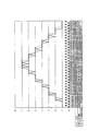
図4に、本発明のコンタリング除去プロセス400を示す。値の差のテスト(図2)、或いは平均化テスト(図3)をパスした後に、プロセッサ70は、ステップ405で、コンタリング除去プロセス400を開始する。最初にステップ410で、プロセッサ70は、所定の画素範囲の画素成分の平均値を計算する。次にステップ415で、プロセッサ70は、その画素成分の平均値を、所定のビット幅(画素成分値の元のビット幅+付加的数の最下位ビットLSB)に詰める(例えば、端数を丸める、または切り捨てる)。その後、プロセッサ70は、ステップ420で、中央(または中央付近)の画素成分値(例えば、8画素範囲の4番目の画素値)を、詰められた平均値で置き替える。次に、ステップ425で、コンタリング検出プロセス200(図2)と300(図3)に従って、次の画素成分値をテストする。一連の入力画素成分値(図7に例示する)と、コンタリング除去プロセス400で発生される一連の出力画素成分値とのグラフによる比較を図9に示す。図9において、1個のLSB(最下位ビット)が加えられている。
FIG. 4 illustrates a
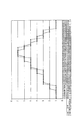
図5に、本発明の別のコンタリング除去プロセス500を示す。値の差のテスト(図2)または平均化テスト(図3)をパスした後に、プロセッサ70は、ステップ505で、コンタリング除去プロセス500を開始する。最初にステップ510で、所定の画素範囲の画素成分の平均値を計算する。その後、ステップ515で、この平均値を最も近い整数に詰めて(端数を丸めるか、切り捨てる)、新しい画素成分値を発生する。次にステップ520で、中央または中央付近の画素成分値(例:8画素範囲のうち4番目の画素値)を、詰められた平均画素成分値で置き替える。次に、プロセッサ70は、ステップ525で、検出プロセス200(図2)/300(図3)に従って、次の画素成分値をテストする。一連の入力画素成分値(図7に例示する)と、コンタリング除去プロセス500で発生された一連の出力画素成分値のグラフによる比較を図8に示す。
FIG. 5 illustrates another
図6に、本発明の別のコンタリング除去プロセス600を示す。値の差のテスト(図2)または平均化テスト(図3)をパスした後に、プロセッサ70は、ステップ605で、プロセス600を開始する。最初にステップ610で、所定の画素範囲の画素成分の平均値を計算する。例えば、8画素範囲における各画素成分値のビット幅が8ビットであれば、平均画素成分値のビット幅は、11ビットになる。その後、ステップ615で、ディザ(dither)信号をこの平均値に加え、新しい画素成分値を発生する。ディザ信号は1と0が交互に並ぶ(1、0、1、0、1、0・・・)ような(しかし、これに限定されない)一連の交番信号である。ディザ信号は、当業者に知られる再帰的丸め回路で実施することもできる。例えば、1と0が交互する2状態のディザ信号を、9ビット加算器を使用して、平均値11ビットに加える。平均値11ビットを9ビットに縮めるために、平均値11ビットの2つのLSBを捨てて、この2状態のディザ信号を(9ビット加算器を介して)平均値9ビットのLSBに加える。別の方法で、11ビット加算器を使用して、2状態のディザ信号を平均値11ビットに加える。2状態のディザ信号は(11ビット加算器を介して)平均値11ビットの3番目のLSBに加えられる。次に、ステップ620で、ディザ処理された画素成分値を、希望のビット幅(例えば、画素成分値の元のビット幅)に縮める。例えば、ディザ処理された平均値9ビットは、そのLSBを除去することにより、ディザ処理された平均値8ビットに縮められ、ディザ処理された11ビットの信号は、3つのLSBを除去することにより、ディザ処理された平均値8ビットに縮められる。その後、ステップ625で、プロセッサ70は、中央または中央付近の画素成分値(例えば、8画素範囲の4番目の画素値)を、縮められた画素成分値で置き替える。次にステップ630で、検出プロセス200(図2)/300(図3)に従って次の画素成分値をテストする。一連の入力画素成分値(図10に例示する)と、プロセス600で発生された一連の出力画素成分値とのグラフによる比較を図11に示す。
FIG. 6 illustrates another
本発明を好ましい実施例に関して説明した。特許請求の範囲で明確にされる本発明の精神と範囲から離れることなく、これらの実施例に種々の変更がなされ得ることは明らかである。 The invention has been described with reference to the preferred embodiment. Obviously, various modifications may be made to these embodiments without departing from the spirit and scope of the invention as defined in the claims.
Claims (8)
複数の画素を含むビデオ信号を受信するステップと、
前記受信したビデオ信号中に、所定数の画素を含む画素範囲を識別するステップと、
前記識別された画素範囲に亘る画素値の総和を計算するステップと、
前記識別された画素範囲の中央または中央付近の画素値に前記識別された画素範囲内の画素の総数を掛けるステップと、
前記掛けられた画素値と計算された画素値の総和との差を計算するステップと、
前記差の絶対値を計算するステップと、
前記計算された差の絶対値が、所定の範囲内にあるならば、前記識別された画素範囲内にコンタリング・アーティファクトが存在すると判定するステップと、
前記識別された画素範囲内の画素を、コンタリング・アーティファクトが除去されるように処理するステップと、
を含む、前記方法。A method for removing contouring artifacts caused by image display,
Receiving a video signal including a plurality of pixels;
Identifying a pixel range including a predetermined number of pixels in the received video signal;
Calculating a sum of pixel values over the identified pixel range;
Multiplying the pixel value at or near the center of the identified pixel range by the total number of pixels in the identified pixel range;
Calculating a difference between the multiplied pixel value and the sum of the calculated pixel values;
Calculating an absolute value of the difference;
Determining that there is a contouring artifact within the identified pixel range if the absolute value of the calculated difference is within a predetermined range;
Processing pixels within the identified pixel range such that contouring artifacts are removed;
Including the method.
圧縮解除された複数の画素を含む復号化されたビデオ信号を受信するステップと、
前記受信した復号化されたビデオ信号中に、所定数の画素を含む画素範囲を識別するステップと、
前記識別された画素範囲内にコンタリング・アーティファクトの存在を検出するステップと、
前記識別された画素範囲の平均画素値を計算するステップと、
前記平均画素値を、前記識別された画素範囲内の各画素のビット幅よりも大きい所定のビット幅に変更するステップと、
前記検出されたコンタリング・アーティファクトが除去されるように、前記識別された画素範囲の画素値を前記変更された平均画素値に替えるステップと、
を含み、前記検出するステップが、更に、
前記識別された画素範囲に亘る画素値の総和を計算するステップと、
前記識別された画素範囲の中央または中央付近の画素値に前記識別された画素範囲内の画素の総数を掛けるステップと、
前記掛けられた画素値と計算された画素値の総和との差を計算するステップと、
を含む、前記方法。A method for removing contouring artifacts caused by image display,
Receiving a decoded video signal including a plurality of decompressed pixels;
Identifying a pixel range including a predetermined number of pixels in the received decoded video signal;
Detecting the presence of a contouring artifact within the identified pixel range;
Calculating an average pixel value of the identified pixel range;
Changing the average pixel value to a predetermined bit width greater than the bit width of each pixel in the identified pixel range; and
Changing the pixel value of the identified pixel range to the modified average pixel value so that the detected contouring artifact is removed;
And the detecting step further comprises:
Calculating a sum of pixel values over the identified pixel range;
Multiplying the pixel value at or near the center of the identified pixel range by the total number of pixels in the identified pixel range;
Calculating a difference between the multiplied pixel value and the sum of the calculated pixel values;
Including the method.
圧縮解除された複数の画素を含む復号化されたビデオ信号を受信するステップと、
前記受信した復号化されたビデオ信号中に、所定数の画素を含む画素範囲を識別するステップと、
前記識別された画素範囲内にコンタリング・アーティファクトの存在を検出するステップと、
前記識別された画素範囲の平均画素値を計算するステップと、
前記平均画素値を最も近い整数に変更して、代替画素値を発生するステップと、
前記検出されたコンタリング・アーティファクトが除去されるように、前記識別された画素範囲の画素値を前記代替画素値に替えるステップと、
を含み、前記検出するステップが、更に、
前記識別された画素範囲に亘る画素値の総和を計算するステップと、
前記識別された画素範囲の中央または中央付近の画素値に前記識別された画素範囲内の画素の総数を掛けるステップと、
前記掛けられた画素値と計算された画素値の総和との差を計算するステップと、
を含む、前記方法。A method for removing contouring artifacts caused by image display,
Receiving a decoded video signal including a plurality of decompressed pixels;
Identifying a pixel range including a predetermined number of pixels in the received decoded video signal;
Detecting the presence of a contouring artifact within the identified pixel range;
Calculating an average pixel value of the identified pixel range;
Changing the average pixel value to the nearest integer to generate a substitute pixel value;
Changing the pixel value of the identified pixel range to the alternative pixel value such that the detected contouring artifact is removed;
And the detecting step further comprises:
Calculating a sum of pixel values over the identified pixel range;
Multiplying the pixel value at or near the center of the identified pixel range by the total number of pixels in the identified pixel range;
Calculating a difference between the multiplied pixel value and the sum of the calculated pixel values;
Including the method.
圧縮解除された複数の画素の各画素が3つの画素成分で構成される、前記圧縮解除された複数の画素を含む復号化されたビデオ信号を受信するステップと、
前記受信した復号化されたビデオ信号中に、所定数の画素成分を含む画素成分範囲を識別するステップと、
前記識別された画素成分範囲内にコンタリング・アーティファクトの存在を検出するステップと、
前記識別された画素成分範囲内の画素成分を、検出されたコンタリング・アーティファクトが除去されるように処理するステップと、
前記識別するステップ、前記検出するステップ、および前記処理するステップを、前記3つの画素成分の各々について別個に繰り返すステップと、
を含み、前記検出するステップが、更に、
前記識別された画素範囲に亘る画素値の総和を計算するステップと、
前記識別された画素範囲の中央または中央付近の画素値に前記識別された画素範囲内の画素の総数を掛けるステップと、
前記掛けられた画素値と計算された画素値の総和との差を計算するステップと、
を含む、前記方法。A method for removing contouring artifacts caused by image display,
Receiving a decoded video signal including the plurality of decompressed pixels, wherein each pixel of the plurality of decompressed pixels is comprised of three pixel components;
Identifying a pixel component range including a predetermined number of pixel components in the received decoded video signal;
Detecting the presence of a contouring artifact within the identified pixel component range;
Processing pixel components within the identified pixel component range such that detected contouring artifacts are removed;
Repeating the identifying, detecting, and processing steps separately for each of the three pixel components;
And the detecting step further comprises:
Calculating a sum of pixel values over the identified pixel range;
Multiplying the pixel value at or near the center of the identified pixel range by the total number of pixels in the identified pixel range;
Calculating a difference between the multiplied pixel value and the sum of the calculated pixel values;
Including the method.
複数の画素を含むビデオ信号を受信する手段と、
前記受信したビデオ信号中に、所定数の画素を含む画素範囲を識別する手段と、
前記識別された画素範囲に亘る画素値の総和を計算する手段と、
前記識別された画素範囲の中央または中央付近の画素値に、前記識別された画素範囲内の全画素数を掛ける手段と、
前記掛けられた画素値と計算された画素値の総和との差を計算する手段と、
前記計算された差の絶対値が所定の範囲内にあるならば、前記識別された画素範囲内にコンタリング・アーティファクトが存在すると判定する手段と、
前記識別された画素範囲内の画素を、コンタリング・アーティファクトが除去されるように処理する手段と、
を含む、前記システム。A system that removes contouring artifacts caused by image display,
Means for receiving a video signal including a plurality of pixels;
Means for identifying a pixel range including a predetermined number of pixels in the received video signal;
Means for calculating a sum of pixel values over the identified pixel range;
Means for multiplying the pixel value at or near the center of the identified pixel range by the total number of pixels in the identified pixel range;
Means for calculating a difference between the multiplied pixel value and the sum of the calculated pixel values;
Means for determining that a contouring artifact is present in the identified pixel range if the absolute value of the calculated difference is within a predetermined range;
Means for processing pixels within said identified pixel range such that contouring artifacts are removed;
Including the system.
圧縮解除された複数の画素を含む復号化されたビデオ信号を受信する手段と、
前記受信した復号化されたビデオ信号中に、所定数の画素を含む画素範囲を識別する手段と、
前記識別された画素範囲内にコンタリング・アーティファクトの存在を検出する手段と、
前記識別された画素範囲の平均画素値を計算する手段と、
前記平均画素値を、前記識別された画素範囲内の各画素のビット幅よりも大きい所定のビット幅に変更する手段と、
前記検出されたコンタリング・アーティファクトが除去されるように、前記識別された画素範囲の画素値を前記変更された平均画素値に替える手段と、
を含み、前記検出する手段が、更に、
前記識別された画素範囲に亘る画素値の総和を計算する手段と、
前記識別された画素範囲の中央または中央付近の画素値に、前記識別された画素範囲内の全画素数を掛ける手段と、
前記掛けられた画素値と計算された画素値の総和との差を計算する手段と、
を含む、前記システム。A system that removes contouring artifacts caused by image display,
Means for receiving a decoded video signal comprising a plurality of decompressed pixels;
Means for identifying a pixel range including a predetermined number of pixels in the received decoded video signal;
Means for detecting the presence of a contouring artifact in the identified pixel range;
Means for calculating an average pixel value of the identified pixel range;
Means for changing the average pixel value to a predetermined bit width greater than the bit width of each pixel in the identified pixel range;
Means for replacing pixel values of the identified pixel range with the modified average pixel values so that the detected contouring artifacts are removed;
And the means for detecting further comprises:
Means for calculating a sum of pixel values over the identified pixel range;
Means for multiplying the pixel value at or near the center of the identified pixel range by the total number of pixels in the identified pixel range;
Means for calculating a difference between the multiplied pixel value and the sum of the calculated pixel values;
Including the system.
圧縮解除された複数の画素を含む復号化されたビデオ信号を受信する手段と、
前記受信した復号化されたビデオ信号中に、所定数の画素を含む画素範囲を識別する手段と、
前記識別された画素範囲内にコンタリング・アーティファクトの存在を検出する手段と、
前記識別された画素範囲の平均画素値を計算する手段と、
前記平均画素値を最も近い整数に変更して、代替画素値を発生する手段と、
前記検出されたコンタリング・アーティファクトが除去されるように、前記識別された画素範囲の画素値を前記代替画素値に替える手段と、
を含み、前記検出する手段が、更に、
前記識別された画素範囲に亘る画素値の総和を計算する手段と、
前記識別された画素範囲の中央または中央付近の画素値に、前記識別された画素範囲内の全画素数を掛ける手段と、
前記掛けられた画素値と計算された画素値の総和との差を計算する手段と、
を含む、前記システム。A system that removes contouring artifacts caused by image display,
Means for receiving a decoded video signal comprising a plurality of decompressed pixels;
Means for identifying a pixel range including a predetermined number of pixels in the received decoded video signal;
Means for detecting the presence of a contouring artifact in the identified pixel range;
Means for calculating an average pixel value of the identified pixel range;
Means for generating an alternative pixel value by changing the average pixel value to the nearest integer;
Means for replacing a pixel value of the identified pixel range with the alternative pixel value such that the detected contouring artifact is removed;
And the means for detecting further comprises:
Means for calculating a sum of pixel values over the identified pixel range;
Means for multiplying the pixel value at or near the center of the identified pixel range by the total number of pixels in the identified pixel range;
Means for calculating a difference between the multiplied pixel value and the sum of the calculated pixel values;
Including the system.
圧縮解除された複数の画素の各画素が3つの画素成分で構成される、前記圧縮解除された複数の画素を含む復号化されたビデオ信号を受信する手段と、
前記受信した復号化されたビデオ信号中の各画素の前記3つの画素成分の各々について、所定数の画素成分を含む画素成分範囲を別々に識別する手段と、
前記別々に識別された各画素成分範囲内にコンタリング・アーティファクトの存在を検出する手段と、
前記別々に識別された各画素成分範囲内の画素成分を、前記検出されたコンタリング・アーティファクトが除去されるように処理する手段と、
を含み、前記検出する手段が、更に、
前記識別された画素範囲に亘る画素値の総和を計算する手段と、
前記識別された画素範囲の中央または中央付近の画素値に、前記識別された画素範囲内の全画素数を掛ける手段と、
前記掛けられた画素値と計算された画素値の総和との差を計算する手段と、
を含む、前記システム。A system that removes contouring artifacts caused by image display,
Means for receiving a decoded video signal comprising the plurality of decompressed pixels, wherein each pixel of the plurality of decompressed pixels is comprised of three pixel components;
Means for separately identifying a pixel component range including a predetermined number of pixel components for each of the three pixel components of each pixel in the received decoded video signal;
Means for detecting the presence of contouring artifacts within each separately identified pixel component range;
Means for processing pixel components within each separately identified pixel component range such that the detected contouring artifacts are removed;
And the means for detecting further comprises:
Means for calculating a sum of pixel values over the identified pixel range;
Means for multiplying the pixel value at or near the center of the identified pixel range by the total number of pixels in the identified pixel range;
Means for calculating a difference between the multiplied pixel value and the sum of the calculated pixel values;
Including the system.
Applications Claiming Priority (3)
| Application Number | Priority Date | Filing Date | Title |
|---|---|---|---|
| US10/056,595 US6647152B2 (en) | 2002-01-25 | 2002-01-25 | Method and system for contouring reduction |
| US10/056,595 | 2002-01-25 | ||
| PCT/US2003/001525 WO2003065293A1 (en) | 2002-01-25 | 2003-01-17 | Method and system for contouring reduction |
Publications (3)
| Publication Number | Publication Date |
|---|---|
| JP2005516260A JP2005516260A (en) | 2005-06-02 |
| JP2005516260A5 JP2005516260A5 (en) | 2006-03-02 |
| JP4740539B2 true JP4740539B2 (en) | 2011-08-03 |
Family
ID=27609300
Family Applications (1)
| Application Number | Title | Priority Date | Filing Date |
|---|---|---|---|
| JP2003564810A Expired - Fee Related JP4740539B2 (en) | 2002-01-25 | 2003-01-17 | Method and system for removing contouring artifacts |
Country Status (10)
| Country | Link |
|---|---|
| US (1) | US6647152B2 (en) |
| EP (1) | EP1468397A4 (en) |
| JP (1) | JP4740539B2 (en) |
| KR (2) | KR101000718B1 (en) |
| CN (1) | CN1307592C (en) |
| BR (1) | BR0307078A (en) |
| MX (1) | MXPA04007139A (en) |
| MY (1) | MY134337A (en) |
| TW (1) | TW591936B (en) |
| WO (1) | WO2003065293A1 (en) |
Families Citing this family (39)
| Publication number | Priority date | Publication date | Assignee | Title |
|---|---|---|---|---|
| US6885383B2 (en) * | 2002-03-08 | 2005-04-26 | David Muresan | Moving-pixels procedure for digital picture edge-smoothing |
| EP1387340A1 (en) * | 2002-07-30 | 2004-02-04 | Deutsche Thomson-Brandt Gmbh | Method and device for processing video data for a display |
| JP2004078059A (en) * | 2002-08-22 | 2004-03-11 | Rohm Co Ltd | Display device |
| JP3877694B2 (en) * | 2003-03-28 | 2007-02-07 | 三洋電機株式会社 | Display processing device |
| US8218624B2 (en) | 2003-07-18 | 2012-07-10 | Microsoft Corporation | Fractional quantization step sizes for high bit rates |
| US7602851B2 (en) | 2003-07-18 | 2009-10-13 | Microsoft Corporation | Intelligent differential quantization of video coding |
| US10554985B2 (en) | 2003-07-18 | 2020-02-04 | Microsoft Technology Licensing, Llc | DC coefficient signaling at small quantization step sizes |
| US7738554B2 (en) | 2003-07-18 | 2010-06-15 | Microsoft Corporation | DC coefficient signaling at small quantization step sizes |
| US7580584B2 (en) | 2003-07-18 | 2009-08-25 | Microsoft Corporation | Adaptive multiple quantization |
| US7801383B2 (en) | 2004-05-15 | 2010-09-21 | Microsoft Corporation | Embedded scalar quantizers with arbitrary dead-zone ratios |
| US7542620B1 (en) * | 2004-08-16 | 2009-06-02 | Apple Inc. | Robust temporal dithering and filtering |
| US7675872B2 (en) * | 2004-11-30 | 2010-03-09 | Broadcom Corporation | System, method, and apparatus for displaying pictures |
| KR100594738B1 (en) * | 2004-12-28 | 2006-06-30 | 삼성전자주식회사 | Apparatus for removing contour caused by reducing bit depth |
| JP4463705B2 (en) | 2005-03-01 | 2010-05-19 | 三菱電機株式会社 | Image display device and image display method |
| US8422546B2 (en) | 2005-05-25 | 2013-04-16 | Microsoft Corporation | Adaptive video encoding using a perceptual model |
| KR100627615B1 (en) * | 2005-12-29 | 2006-09-25 | 엠텍비젼 주식회사 | Apparatus for removing color interpolation by using adjustable threshold |
| JP4455513B2 (en) * | 2006-02-13 | 2010-04-21 | 三菱電機株式会社 | Image processing method, image processing apparatus, and image display apparatus |
| KR20070099170A (en) * | 2006-04-03 | 2007-10-09 | 엘지.필립스 엘시디 주식회사 | Apparatus and method for driving data, apparatus and method for driving of image display device using the same |
| US8503536B2 (en) | 2006-04-07 | 2013-08-06 | Microsoft Corporation | Quantization adjustments for DC shift artifacts |
| US8130828B2 (en) | 2006-04-07 | 2012-03-06 | Microsoft Corporation | Adjusting quantization to preserve non-zero AC coefficients |
| US8059721B2 (en) | 2006-04-07 | 2011-11-15 | Microsoft Corporation | Estimating sample-domain distortion in the transform domain with rounding compensation |
| US7974340B2 (en) | 2006-04-07 | 2011-07-05 | Microsoft Corporation | Adaptive B-picture quantization control |
| US7995649B2 (en) * | 2006-04-07 | 2011-08-09 | Microsoft Corporation | Quantization adjustment based on texture level |
| US8711925B2 (en) | 2006-05-05 | 2014-04-29 | Microsoft Corporation | Flexible quantization |
| TWI466547B (en) * | 2007-01-05 | 2014-12-21 | Marvell World Trade Ltd | Methods and systems for improving low-resolution video |
| JP5237968B2 (en) * | 2007-01-19 | 2013-07-17 | トムソン ライセンシング | Identification of banding in digital images |
| US8238424B2 (en) | 2007-02-09 | 2012-08-07 | Microsoft Corporation | Complexity-based adaptive preprocessing for multiple-pass video compression |
| US8498335B2 (en) | 2007-03-26 | 2013-07-30 | Microsoft Corporation | Adaptive deadzone size adjustment in quantization |
| US8243797B2 (en) | 2007-03-30 | 2012-08-14 | Microsoft Corporation | Regions of interest for quality adjustments |
| US7864191B2 (en) * | 2007-04-16 | 2011-01-04 | Texas Instruments Incorporated | Techniques for efficient dithering |
| US8442337B2 (en) | 2007-04-18 | 2013-05-14 | Microsoft Corporation | Encoding adjustments for animation content |
| US8331438B2 (en) | 2007-06-05 | 2012-12-11 | Microsoft Corporation | Adaptive selection of picture-level quantization parameters for predicted video pictures |
| US8189933B2 (en) | 2008-03-31 | 2012-05-29 | Microsoft Corporation | Classifying and controlling encoding quality for textured, dark smooth and smooth video content |
| US8897359B2 (en) | 2008-06-03 | 2014-11-25 | Microsoft Corporation | Adaptive quantization for enhancement layer video coding |
| US8270498B2 (en) * | 2009-03-26 | 2012-09-18 | Apple Inc. | Dynamic dithering for video compression |
| US8860750B2 (en) * | 2011-03-08 | 2014-10-14 | Apple Inc. | Devices and methods for dynamic dithering |
| KR102007815B1 (en) * | 2012-12-12 | 2019-08-07 | 엘지디스플레이 주식회사 | Display device and image data processing method thereof |
| US9092856B2 (en) * | 2013-10-31 | 2015-07-28 | Stmicroelectronics Asia Pacific Pte. Ltd. | Recursive de-banding filter for digital images |
| CN108322723B (en) * | 2018-02-06 | 2020-01-24 | 深圳创维-Rgb电子有限公司 | Color distortion compensation method and device and television |
Citations (16)
| Publication number | Priority date | Publication date | Assignee | Title |
|---|---|---|---|---|
| JPS6319982A (en) * | 1986-07-12 | 1988-01-27 | Fujitsu Ltd | Gradation control system for video printer |
| JPS63285076A (en) * | 1987-05-18 | 1988-11-22 | Canon Inc | Picture processing method |
| JPH03226177A (en) * | 1990-01-31 | 1991-10-07 | Fuji Xerox Co Ltd | Gradation conversion processing unit |
| JPH0490680A (en) * | 1990-08-06 | 1992-03-24 | Oki Electric Ind Co Ltd | Picture binarizing method |
| JPH04165874A (en) * | 1990-10-30 | 1992-06-11 | Canon Inc | Digital signal processor |
| JPH06152992A (en) * | 1992-10-29 | 1994-05-31 | Canon Inc | Picture processing method and device |
| JPH06225179A (en) * | 1993-01-21 | 1994-08-12 | Sony Corp | Quantizer for picture signal |
| JPH06326859A (en) * | 1993-05-14 | 1994-11-25 | Ricoh Co Ltd | Picture processing unit |
| JPH0944648A (en) * | 1995-08-01 | 1997-02-14 | Sony Corp | Image processing device and method therefor |
| WO1999050384A1 (en) * | 1998-03-31 | 1999-10-07 | Micro Gaia Co., Ltd. | Fine algae culture device |
| JPH11272228A (en) * | 1998-03-19 | 1999-10-08 | Mitsubishi Electric Corp | Display drive unit and method thereof |
| JP2000101846A (en) * | 1998-09-18 | 2000-04-07 | Fuji Xerox Co Ltd | Image information coder |
| JP2001036756A (en) * | 1999-07-15 | 2001-02-09 | Canon Inc | Method and device for processing image |
| JP2001092954A (en) * | 1999-09-20 | 2001-04-06 | Matsushita Electric Ind Co Ltd | Rounding processor |
| JP2001136535A (en) * | 1999-08-25 | 2001-05-18 | Fuji Xerox Co Ltd | Image-encoding device and quantization characteristic determining device |
| JP2001519632A (en) * | 1997-10-06 | 2001-10-23 | テレディフュジオン・ドゥ・フランス | Method for assessing the degradation of a video image introduced by a digital transmission and / or recording and / or encoding system |
Family Cites Families (17)
| Publication number | Priority date | Publication date | Assignee | Title |
|---|---|---|---|---|
| JPS605692A (en) | 1983-06-24 | 1985-01-12 | Victor Co Of Japan Ltd | Video signal processing device |
| US5838298A (en) | 1987-02-13 | 1998-11-17 | Canon Kabushiki Kaisha | Image processing apparatus and method for smoothing stairway-like portions of a contour line of an image |
| US5138303A (en) | 1989-10-31 | 1992-08-11 | Microsoft Corporation | Method and apparatus for displaying color on a computer output device using dithering techniques |
| US5218649A (en) * | 1990-05-04 | 1993-06-08 | U S West Advanced Technologies, Inc. | Image enhancement system |
| US5374963A (en) | 1990-06-01 | 1994-12-20 | Thomson Consumer Electronics, Inc. | Picture resolution enhancement with dithering and dedithering |
| US5101452A (en) | 1990-12-17 | 1992-03-31 | Eastman Kodak Company | Apparatus and method for dynamic step quantization |
| DE69324513T2 (en) * | 1992-02-11 | 1999-10-21 | Eastman Kodak Co | Image production system and associated method for minimizing contours for a quantized digital color image |
| JP3222183B2 (en) * | 1992-02-19 | 2001-10-22 | 株式会社リコー | Image processing device |
| US5651078A (en) * | 1994-07-18 | 1997-07-22 | Thomson Consumer Electronics, Inc. | Method and apparatus for reducing contouring in video compression |
| US6147671A (en) | 1994-09-13 | 2000-11-14 | Intel Corporation | Temporally dissolved dithering |
| KR100414432B1 (en) * | 1995-03-24 | 2004-03-18 | 마츠시타 덴끼 산교 가부시키가이샤 | Contour extraction device |
| US5579054A (en) * | 1995-04-21 | 1996-11-26 | Eastman Kodak Company | System and method for creating high-quality stills from interlaced video |
| US6040876A (en) | 1995-10-13 | 2000-03-21 | Texas Instruments Incorporated | Low intensity contouring and color shift reduction using dither |
| US5777624A (en) | 1996-01-02 | 1998-07-07 | Intel Corporation | Method and apparatus for eliminating visual artifacts caused by diffusing errors in a decimated video signal |
| JP4067594B2 (en) | 1996-01-26 | 2008-03-26 | テキサス インスツルメンツ インコーポレイテツド | Signal conversion circuit and method of converting input word to digital output word |
| US5835117A (en) * | 1996-05-31 | 1998-11-10 | Eastman Kodak Company | Nonlinear dithering to reduce neutral toe color shifts |
| US6324310B1 (en) * | 1998-06-02 | 2001-11-27 | Digital Persona, Inc. | Method and apparatus for scanning a fingerprint using a linear sensor |
-
2002
- 2002-01-25 US US10/056,595 patent/US6647152B2/en not_active Expired - Lifetime
-
2003
- 2003-01-17 JP JP2003564810A patent/JP4740539B2/en not_active Expired - Fee Related
- 2003-01-17 BR BR0307078-6A patent/BR0307078A/en not_active Application Discontinuation
- 2003-01-17 TW TW092101006A patent/TW591936B/en not_active IP Right Cessation
- 2003-01-17 EP EP03703878.3A patent/EP1468397A4/en not_active Withdrawn
- 2003-01-17 WO PCT/US2003/001525 patent/WO2003065293A1/en active Application Filing
- 2003-01-17 MX MXPA04007139A patent/MXPA04007139A/en active IP Right Grant
- 2003-01-17 CN CNB038026538A patent/CN1307592C/en not_active Expired - Fee Related
- 2003-01-17 KR KR1020047011454A patent/KR101000718B1/en active IP Right Grant
- 2003-01-17 KR KR1020107016890A patent/KR20100089906A/en not_active Application Discontinuation
- 2003-01-24 MY MYPI20030243A patent/MY134337A/en unknown
Patent Citations (16)
| Publication number | Priority date | Publication date | Assignee | Title |
|---|---|---|---|---|
| JPS6319982A (en) * | 1986-07-12 | 1988-01-27 | Fujitsu Ltd | Gradation control system for video printer |
| JPS63285076A (en) * | 1987-05-18 | 1988-11-22 | Canon Inc | Picture processing method |
| JPH03226177A (en) * | 1990-01-31 | 1991-10-07 | Fuji Xerox Co Ltd | Gradation conversion processing unit |
| JPH0490680A (en) * | 1990-08-06 | 1992-03-24 | Oki Electric Ind Co Ltd | Picture binarizing method |
| JPH04165874A (en) * | 1990-10-30 | 1992-06-11 | Canon Inc | Digital signal processor |
| JPH06152992A (en) * | 1992-10-29 | 1994-05-31 | Canon Inc | Picture processing method and device |
| JPH06225179A (en) * | 1993-01-21 | 1994-08-12 | Sony Corp | Quantizer for picture signal |
| JPH06326859A (en) * | 1993-05-14 | 1994-11-25 | Ricoh Co Ltd | Picture processing unit |
| JPH0944648A (en) * | 1995-08-01 | 1997-02-14 | Sony Corp | Image processing device and method therefor |
| JP2001519632A (en) * | 1997-10-06 | 2001-10-23 | テレディフュジオン・ドゥ・フランス | Method for assessing the degradation of a video image introduced by a digital transmission and / or recording and / or encoding system |
| JPH11272228A (en) * | 1998-03-19 | 1999-10-08 | Mitsubishi Electric Corp | Display drive unit and method thereof |
| WO1999050384A1 (en) * | 1998-03-31 | 1999-10-07 | Micro Gaia Co., Ltd. | Fine algae culture device |
| JP2000101846A (en) * | 1998-09-18 | 2000-04-07 | Fuji Xerox Co Ltd | Image information coder |
| JP2001036756A (en) * | 1999-07-15 | 2001-02-09 | Canon Inc | Method and device for processing image |
| JP2001136535A (en) * | 1999-08-25 | 2001-05-18 | Fuji Xerox Co Ltd | Image-encoding device and quantization characteristic determining device |
| JP2001092954A (en) * | 1999-09-20 | 2001-04-06 | Matsushita Electric Ind Co Ltd | Rounding processor |
Also Published As
| Publication number | Publication date |
|---|---|
| KR20100089906A (en) | 2010-08-12 |
| KR101000718B1 (en) | 2010-12-10 |
| EP1468397A4 (en) | 2017-05-10 |
| CN1307592C (en) | 2007-03-28 |
| TW591936B (en) | 2004-06-11 |
| TW200302662A (en) | 2003-08-01 |
| CN1623165A (en) | 2005-06-01 |
| KR20040075108A (en) | 2004-08-26 |
| US6647152B2 (en) | 2003-11-11 |
| US20030142878A1 (en) | 2003-07-31 |
| EP1468397A1 (en) | 2004-10-20 |
| BR0307078A (en) | 2004-12-28 |
| MXPA04007139A (en) | 2004-10-29 |
| MY134337A (en) | 2007-12-31 |
| WO2003065293A1 (en) | 2003-08-07 |
| JP2005516260A (en) | 2005-06-02 |
Similar Documents
| Publication | Publication Date | Title |
|---|---|---|
| JP4740539B2 (en) | Method and system for removing contouring artifacts | |
| US10192294B2 (en) | Image processing apparatus and image processing method for display mapping | |
| US6400767B1 (en) | Communication of HBI data in digital television data streams | |
| RU2128405C1 (en) | Device for encoding of video signal which represents images, tv set for receiving signal with headers and image data represented as compressed video data | |
| JP4067579B2 (en) | Video signal encoding system | |
| EP1158810B1 (en) | Recording medium | |
| US7750938B2 (en) | Method and system for maintaining even tube burn-in | |
| CN101248675B (en) | Broadcast receiving apparatus, broadcast receiving method and broadcast receiving circuit | |
| HUT75274A (en) | Digital video transmitting system | |
| JPH1132330A (en) | Image coder, image coding method, image decoder and image decoding method, and image processing unit and image processing method | |
| CN1065569A (en) | The equipment that is used for recombining prioritized video data | |
| CN1065568A (en) | The device that is used for segmenting encoded video signal for transmission | |
| US7830968B1 (en) | Apparatus for providing a video lip sync delay and method therefore | |
| JP2006518561A (en) | Method and apparatus for preventing error propagation in a video sequence | |
| US20060093037A1 (en) | Device and method for decoding and digital broadcast receiving apparatus | |
| JPH06261306A (en) | Video signal encoding/decoding device | |
| JPH07184198A (en) | Video signal compression/expansion processing unit | |
| JP2000049730A (en) | Transmission device, reception device and transmission system using them | |
| JP2000036751A (en) | Transmitter and receiver, and transmission system using the same | |
| JP2008178155A (en) | Isdb transmitter and isdb transmission method, and isdb receiver and isdb reception method | |
| JPH05308524A (en) | Image processor | |
| JP2000049729A (en) | Transmission device, reception device and transmission system using them | |
| JP2000049727A (en) | Transmitting method, receiving method and transmission method using them | |
| JP2000049728A (en) | Transmission device, reception device and transmission system using them | |
| JP2000059343A (en) | Transmission method, reception method and delivery method using them |
Legal Events
| Date | Code | Title | Description |
|---|---|---|---|
| A711 | Notification of change in applicant |
Free format text: JAPANESE INTERMEDIATE CODE: A711 Effective date: 20050315 |
|
| A521 | Request for written amendment filed |
Free format text: JAPANESE INTERMEDIATE CODE: A821 Effective date: 20050315 |
|
| A521 | Request for written amendment filed |
Free format text: JAPANESE INTERMEDIATE CODE: A523 Effective date: 20060112 |
|
| A621 | Written request for application examination |
Free format text: JAPANESE INTERMEDIATE CODE: A621 Effective date: 20060112 |
|
| RD03 | Notification of appointment of power of attorney |
Free format text: JAPANESE INTERMEDIATE CODE: A7423 Effective date: 20060929 |
|
| RD04 | Notification of resignation of power of attorney |
Free format text: JAPANESE INTERMEDIATE CODE: A7424 Effective date: 20061120 |
|
| RD05 | Notification of revocation of power of attorney |
Free format text: JAPANESE INTERMEDIATE CODE: A7425 Effective date: 20080318 |
|
| RD04 | Notification of resignation of power of attorney |
Free format text: JAPANESE INTERMEDIATE CODE: A7424 Effective date: 20080415 |
|
| A131 | Notification of reasons for refusal |
Free format text: JAPANESE INTERMEDIATE CODE: A131 Effective date: 20090826 |
|
| RD02 | Notification of acceptance of power of attorney |
Free format text: JAPANESE INTERMEDIATE CODE: A7422 Effective date: 20090903 |
|
| RD04 | Notification of resignation of power of attorney |
Free format text: JAPANESE INTERMEDIATE CODE: A7424 Effective date: 20090911 |
|
| A521 | Request for written amendment filed |
Free format text: JAPANESE INTERMEDIATE CODE: A523 Effective date: 20091126 |
|
| A131 | Notification of reasons for refusal |
Free format text: JAPANESE INTERMEDIATE CODE: A131 Effective date: 20100413 |
|
| A601 | Written request for extension of time |
Free format text: JAPANESE INTERMEDIATE CODE: A601 Effective date: 20100709 |
|
| A602 | Written permission of extension of time |
Free format text: JAPANESE INTERMEDIATE CODE: A602 Effective date: 20100716 |
|
| A521 | Request for written amendment filed |
Free format text: JAPANESE INTERMEDIATE CODE: A523 Effective date: 20100930 |
|
| A02 | Decision of refusal |
Free format text: JAPANESE INTERMEDIATE CODE: A02 Effective date: 20101026 |
|
| A521 | Request for written amendment filed |
Free format text: JAPANESE INTERMEDIATE CODE: A523 Effective date: 20110223 |
|
| A911 | Transfer to examiner for re-examination before appeal (zenchi) |
Free format text: JAPANESE INTERMEDIATE CODE: A911 Effective date: 20110301 |
|
| TRDD | Decision of grant or rejection written | ||
| A01 | Written decision to grant a patent or to grant a registration (utility model) |
Free format text: JAPANESE INTERMEDIATE CODE: A01 Effective date: 20110405 |
|
| A61 | First payment of annual fees (during grant procedure) |
Free format text: JAPANESE INTERMEDIATE CODE: A61 Effective date: 20110502 |
|
| R150 | Certificate of patent or registration of utility model |
Ref document number: 4740539 Country of ref document: JP Free format text: JAPANESE INTERMEDIATE CODE: R150 Free format text: JAPANESE INTERMEDIATE CODE: R150 |
|
| FPAY | Renewal fee payment (event date is renewal date of database) |
Free format text: PAYMENT UNTIL: 20140513 Year of fee payment: 3 |
|
| R250 | Receipt of annual fees |
Free format text: JAPANESE INTERMEDIATE CODE: R250 |
|
| S111 | Request for change of ownership or part of ownership |
Free format text: JAPANESE INTERMEDIATE CODE: R313113 |
|
| S531 | Written request for registration of change of domicile |
Free format text: JAPANESE INTERMEDIATE CODE: R313531 |
|
| R250 | Receipt of annual fees |
Free format text: JAPANESE INTERMEDIATE CODE: R250 |
|
| R371 | Transfer withdrawn |
Free format text: JAPANESE INTERMEDIATE CODE: R371 |
|
| R371 | Transfer withdrawn |
Free format text: JAPANESE INTERMEDIATE CODE: R371 |
|
| S531 | Written request for registration of change of domicile |
Free format text: JAPANESE INTERMEDIATE CODE: R313531 |
|
| R350 | Written notification of registration of transfer |
Free format text: JAPANESE INTERMEDIATE CODE: R350 |
|
| S111 | Request for change of ownership or part of ownership |
Free format text: JAPANESE INTERMEDIATE CODE: R313113 |
|
| R350 | Written notification of registration of transfer |
Free format text: JAPANESE INTERMEDIATE CODE: R350 |
|
| LAPS | Cancellation because of no payment of annual fees |