JP4714115B2 - 3D image display apparatus and 3D image display method - Google Patents
3D image display apparatus and 3D image display method Download PDFInfo
- Publication number
- JP4714115B2 JP4714115B2 JP2006243255A JP2006243255A JP4714115B2 JP 4714115 B2 JP4714115 B2 JP 4714115B2 JP 2006243255 A JP2006243255 A JP 2006243255A JP 2006243255 A JP2006243255 A JP 2006243255A JP 4714115 B2 JP4714115 B2 JP 4714115B2
- Authority
- JP
- Japan
- Prior art keywords
- image
- parallax
- image display
- stereoscopic
- warning
- Prior art date
- Legal status (The legal status is an assumption and is not a legal conclusion. Google has not performed a legal analysis and makes no representation as to the accuracy of the status listed.)
- Expired - Fee Related
Links
- 238000000034 method Methods 0.000 title claims description 62
- 238000006243 chemical reaction Methods 0.000 claims description 21
- 230000000737 periodic effect Effects 0.000 claims description 21
- 230000003287 optical effect Effects 0.000 claims description 9
- 239000011159 matrix material Substances 0.000 claims description 5
- 230000004888 barrier function Effects 0.000 description 18
- 238000010586 diagram Methods 0.000 description 15
- 239000002131 composite material Substances 0.000 description 7
- 239000004973 liquid crystal related substance Substances 0.000 description 4
- 230000000007 visual effect Effects 0.000 description 4
- 230000006835 compression Effects 0.000 description 3
- 238000007906 compression Methods 0.000 description 3
- 238000003384 imaging method Methods 0.000 description 3
- 230000000052 comparative effect Effects 0.000 description 2
- 238000009792 diffusion process Methods 0.000 description 2
- 239000011521 glass Substances 0.000 description 2
- 230000002427 irreversible effect Effects 0.000 description 2
- 230000002265 prevention Effects 0.000 description 2
- 230000002159 abnormal effect Effects 0.000 description 1
- 239000000470 constituent Substances 0.000 description 1
- 238000010276 construction Methods 0.000 description 1
- 230000006837 decompression Effects 0.000 description 1
- 230000006866 deterioration Effects 0.000 description 1
- 230000000694 effects Effects 0.000 description 1
- 210000000887 face Anatomy 0.000 description 1
- 239000000463 material Substances 0.000 description 1
- 239000000203 mixture Substances 0.000 description 1
- 239000000758 substrate Substances 0.000 description 1
- 230000002194 synthesizing effect Effects 0.000 description 1
- 239000002699 waste material Substances 0.000 description 1
Images


Classifications
-
- H—ELECTRICITY
- H04—ELECTRIC COMMUNICATION TECHNIQUE
- H04N—PICTORIAL COMMUNICATION, e.g. TELEVISION
- H04N13/00—Stereoscopic video systems; Multi-view video systems; Details thereof
- H04N13/30—Image reproducers
- H04N13/349—Multi-view displays for displaying three or more geometrical viewpoints without viewer tracking
- H04N13/351—Multi-view displays for displaying three or more geometrical viewpoints without viewer tracking for displaying simultaneously
-
- G—PHYSICS
- G03—PHOTOGRAPHY; CINEMATOGRAPHY; ANALOGOUS TECHNIQUES USING WAVES OTHER THAN OPTICAL WAVES; ELECTROGRAPHY; HOLOGRAPHY
- G03B—APPARATUS OR ARRANGEMENTS FOR TAKING PHOTOGRAPHS OR FOR PROJECTING OR VIEWING THEM; APPARATUS OR ARRANGEMENTS EMPLOYING ANALOGOUS TECHNIQUES USING WAVES OTHER THAN OPTICAL WAVES; ACCESSORIES THEREFOR
- G03B27/00—Photographic printing apparatus
- G03B27/02—Exposure apparatus for contact printing
- G03B27/14—Details
- G03B27/18—Maintaining or producing contact pressure between original and light-sensitive material
- G03B27/22—Maintaining or producing contact pressure between original and light-sensitive material by stretching over a curved surface
-
- H—ELECTRICITY
- H04—ELECTRIC COMMUNICATION TECHNIQUE
- H04N—PICTORIAL COMMUNICATION, e.g. TELEVISION
- H04N13/00—Stereoscopic video systems; Multi-view video systems; Details thereof
- H04N13/30—Image reproducers
- H04N13/302—Image reproducers for viewing without the aid of special glasses, i.e. using autostereoscopic displays
- H04N13/305—Image reproducers for viewing without the aid of special glasses, i.e. using autostereoscopic displays using lenticular lenses, e.g. arrangements of cylindrical lenses
-
- H—ELECTRICITY
- H04—ELECTRIC COMMUNICATION TECHNIQUE
- H04N—PICTORIAL COMMUNICATION, e.g. TELEVISION
- H04N13/00—Stereoscopic video systems; Multi-view video systems; Details thereof
- H04N13/30—Image reproducers
- H04N13/302—Image reproducers for viewing without the aid of special glasses, i.e. using autostereoscopic displays
- H04N13/31—Image reproducers for viewing without the aid of special glasses, i.e. using autostereoscopic displays using parallax barriers
Landscapes
- Engineering & Computer Science (AREA)
- Multimedia (AREA)
- Signal Processing (AREA)
- Physics & Mathematics (AREA)
- General Physics & Mathematics (AREA)
- Testing, Inspecting, Measuring Of Stereoscopic Televisions And Televisions (AREA)
- Liquid Crystal (AREA)
Description
本発明は、立体映像表示装置および表示方法に関する。 The present invention relates to a stereoscopic image display device and a display method.
動画表示が可能な立体視画像表示装置、所謂3次元ディスプレイには、種々の方式が知られている。近年、特にフラットパネルタイプで、且つ専用の眼鏡等を必要としない方式の要望が高くなっている。直視型或いは投影型の液晶表示装置やプラズマ表示装置などのような画素位置が固定されている表示パネル(要素画像表示部)の直前に表示パネルからの光線を制御して観察者に向ける光線制御素子を設置する方式が比較的容易に実現できる方式として知られている。 Various methods are known for stereoscopic image display devices capable of displaying moving images, so-called three-dimensional displays. In recent years, there has been a growing demand for a method that is particularly a flat panel type and does not require special glasses. Light control that directs light from a display panel to an observer just before a display panel (element image display unit) having a fixed pixel position such as a direct-view or projection-type liquid crystal display device or plasma display device A method of installing elements is known as a method that can be realized relatively easily.
光線制御素子は、一般的にはパララクスバリア或いは視差バリアとも称せられ、光線制御素子上の同一位置でも角度により異なる画像が見えるように光線を制御している。具体的には、左右視差(水平視差)のみを与える場合には、スリット或いはレンチキュラーシート(シリンドリカルレンズアレイ)が用いられ、上下視差(垂直視差)も含める場合には、ピンホールアレイ或いはレンズアレイが用いられる。視差バリアを用いる方式にも、さらに2眼式、多眼式、超多眼式(多眼式の超多眼条件)、インテグラルフォトグラフィー(以下、IPとも云う)式に分類される。これらの基本的な原理は、100年程度前に発明され立体写真に用いられてきたものと実質上同一である。 The light beam control element is generally called a parallax barrier or a parallax barrier, and controls light beams so that different images can be seen depending on the angle even at the same position on the light beam control element. Specifically, when only left and right parallax (horizontal parallax) is given, a slit or a lenticular sheet (cylindrical lens array) is used. When vertical parallax is also included, a pinhole array or lens array is used. Used. The system using the parallax barrier is further classified into a binocular system, a multi-view system, a super multi-view system (multi-view super multi-view condition), and an integral photography (hereinafter also referred to as IP) system. These basic principles are substantially the same as those invented about 100 years ago and used in stereoscopic photography.
IP方式でも多眼方式でも、通常は視距離が有限であるため、その視距離における透視投影画像が実際に見えるように表示画像を作成する。水平視差のみで垂直視差のないIP方式(1次元IP方式)では、視差バリアの水平方向ピッチが要素画像表示部のサブ画素の水平方向ピッチの整数倍である場合は平行光線の組があるため(以下、平行光線1次元IPとも云う)、垂直方向がある一定視距離の透視投影であり水平方向が平行投影である画像を画素列ごとに分割し表示面に表示される画像形式の視差合成画像に合成することにより、正しい投影の立体像が得られる。具体的な方法は、例えば非特許文献1に開示されている。多眼方式では、単純な透視投影による画像を分割配置することにより、正しい投影の立体像が得られる。
In both the IP system and the multi-view system, since the viewing distance is usually finite, a display image is created so that a perspective projection image at the viewing distance can be actually seen. In the IP method (one-dimensional IP method) with only horizontal parallax and no vertical parallax, there is a set of parallel rays when the horizontal pitch of the parallax barrier is an integral multiple of the horizontal pitch of the sub-pixels of the element image display unit. (Hereinafter also referred to as parallel light one-dimensional IP), an image format parallax composition in which an image in which the vertical direction is a perspective projection with a certain viewing distance and the horizontal direction is a parallel projection is divided into pixel columns and displayed on a display surface By synthesizing the image, a stereoscopic image with a correct projection can be obtained. A specific method is disclosed in
なお、垂直方向と水平方向で投影方法あるいは投影中心距離を異ならせるような撮像装置は、特に平行投影の場合に被写体と同サイズのカメラあるいはレンズが必要となるため、実現が困難である。したがって、撮像により平行投影データを得るためには、透視投影の撮像データから変換する方法が現実的であり、EPI(エピポーラ面)を用いた補間による方法である光線空間法などが知られている。 Note that it is difficult to realize an image pickup apparatus in which the projection method or the projection center distance is different between the vertical direction and the horizontal direction because a camera or a lens having the same size as the subject is required particularly in parallel projection. Therefore, in order to obtain parallel projection data by imaging, a method of converting from perspective projection imaging data is realistic, and a ray space method that is a method by interpolation using EPI (epipolar plane) is known. .
平行光線1次元IP方式は、非特許文献1に開示されているように、2眼方式や多眼方式に比べ、視域が広く運動視差が連続的であり、自然で見やすいというメリットがある。
As disclosed in
2眼や多眼は最も単純な立体画像表示であるため画像フォーマットが単純で、各視点画像はすべて同一サイズであり、2眼なら2枚、9眼なら9枚の視差成分画像を画素列毎に分割して、要素画像表示部に表示される画像形式である視差合成画像に合成すればよい。平行光線1次元IP方式では、同一解像度相当の多眼方式に比較し、視差成分画像の枚数が多く、各視差成分画像のサイズ(使用する水平範囲)も視差方向により異なる。しかし、平行光線1次元IP方式においても、適切な組み合わせにより各視差成分画像を必要範囲のみ無駄なくタイリングでき、変換効率が高く非可逆圧縮時に劣化の少ないフォーマットに変換できることが、特許文献1に開示されている。
Since binoculars and multi-views are the simplest stereoscopic image display, the image format is simple. All viewpoint images have the same size, and two parallax component images for two eyes and nine parallax component images for nine eyes are displayed for each pixel column. And may be combined with a parallax composite image that is an image format displayed on the element image display unit. The parallel light one-dimensional IP method has a larger number of parallax component images than the multi-view method corresponding to the same resolution, and the size (horizontal range to be used) of each parallax component image varies depending on the parallax direction. However, in the parallel light one-dimensional IP method, it is disclosed in
1次元IP方式、2次元IP方式、視差数の多い多眼方式のいずれにおいても、観察者が視域の境界に位置した場合には、偽像すなわち数本の縦線によって割れた異常画像が観察される。これを防止する方法として、要素画像の境界に警告画像データを配置し、偽像のかわりに警告画像が見えるようにする方法が、例えば特許文献2に開示されている。
In any of the one-dimensional IP method, the two-dimensional IP method, and the multi-view method with a large number of parallaxes, when an observer is positioned at the boundary of the viewing zone, a false image, that is, an abnormal image broken by several vertical lines is displayed. Observed. As a method for preventing this, for example,
しかし、連続的な運動視差を持たせるために視差成分間クロストークを利用している場合、単に要素画像の境界に警告画像を配置しても、わずかなグラデーションの周期的パターンが薄く見えるだけで、視認されにくいという問題がある。視認されるように警告画像の領域を増やすと、立体表示の視域が狭くなる。また、警告画像を画像に入れ込む処理も単純ではないため処理の負荷がかかるという問題もある。
上述のように、従来の平行光線1次元IP方式の立体映像表示装置にあっては、単に要素画像の境界に警告画像を配置しても視認されにくく、視域や処理速度の確保と両立させることが困難であるという問題があった。 As described above, in a conventional parallel light one-dimensional IP stereoscopic image display device, even if a warning image is simply placed at the boundary of an element image, it is difficult to be visually recognized, and both a viewing area and a processing speed are ensured. There was a problem that it was difficult.
本発明は、上記事情を考慮してなされたものであり、平行光線1次元IP方式において、視域や処理速度を犠牲にせず、視認性のよい警告画像を視域端に表示することのできる立体映像表示装置および表示方法を提供することを目的とする。 The present invention has been made in consideration of the above circumstances, and in the parallel light one-dimensional IP method, a warning image with high visibility can be displayed at the end of the viewing zone without sacrificing the viewing zone or processing speed. It is an object to provide a stereoscopic video display device and a display method.
本発明の第1の態様による立体映像表示装置は、表示面内に画素がマトリクス状に配列され、それぞれが複数の視差成分画像を含む複数の要素画像を表示する要素画像表示部と、前記要素画像表示部に対向して設置され、略垂直方向に直線状に延びるとともに略水平方向に周期的に並びそれぞれが各要素画像に関連付けられた複数の光学的開口部を有し、前記要素画像表示部からの光線を制御する光線制御素子と、前記要素画像の境界部に、幅が前記要素画像表示部内の位置によって周期的に異なる単色部が、前記要素画像表示部全体で左右非対称に挿入されるように画像データを変換する画像データ変換部と、を備えたことを特徴とする。 The stereoscopic image display device according to the first aspect of the present invention includes an element image display unit that displays a plurality of element images each including a plurality of parallax component images, in which pixels are arranged in a matrix on a display surface. disposed to face the image display unit includes a plurality of optical apertures that are periodically parallel Bisorezore in a substantially horizontal direction associated with each element image extends linearly in a substantially vertical direction, said elements image A light-color control element that controls light from the display unit and a monochromatic part whose width periodically varies depending on the position in the element image display unit are inserted asymmetrically across the element image display unit at the boundary of the element image And an image data conversion unit for converting the image data as described above.
また、本発明の第2の態様による立体映像表示方法は、表示面内に画素がマトリクス状に配列され、それぞれが複数の視差成分画像を含む複数の要素画像を表示する要素画像表示部と、前記要素画像表示部に対向して設置され、略垂直方向に直線状に延びるとともに略水平方向に周期的に並びそれぞれが各要素画像に関連付けられた複数の光学的開口部を有し、前記要素画像表示部からの光線を制御する光線制御素子と、を有する立体映像表示装置を用いて立体映像を表示する立体映像表示方法であって、前記要素画像の境界部に、幅が要素画像表示部内の位置によって周期的に異なる単色部が、要素画像表示部全体で左右非対称に挿入されるように画像データを変換するステップを備えたことを特徴とする。 The stereoscopic image display method according to the second aspect of the present invention includes an element image display unit that displays a plurality of element images each including a plurality of parallax component images, in which pixels are arranged in a matrix on a display surface. the elemental image display section faces to be installed, a plurality of optical apertures that are periodically parallel Bisorezore in a substantially horizontal direction associated with each element image extends linearly in a substantially vertical direction, the A stereoscopic image display method for displaying a stereoscopic image using a stereoscopic image display device having a light beam control element for controlling light rays from an element image display unit, wherein the width of the element image is displayed at a boundary portion of the element image A step of converting the image data so that the monochromatic portion that periodically differs depending on the position in the portion is inserted asymmetrically in the entire element image display portion is provided.
本発明によれば、1次元IP方式において、処理負荷・視域を犠牲にせず、視認性のよい警告画像を視域端に表示することができる。 According to the present invention, in the one-dimensional IP method, it is possible to display a warning image with good visibility at the end of the viewing zone without sacrificing the processing load and the viewing zone.
以下、図面を参照して、本発明の一実施形態による立体映像表示装置を詳細に説明する。 Hereinafter, a stereoscopic image display apparatus according to an embodiment of the present invention will be described in detail with reference to the drawings.
図1は、本発明の一実施形態による立体映像表示装置における画像変換方法を説明するためのデータ空間を表す概念図である。この図1に示すデータ空間は、一般に光線空間(EPI)として知られているものとほぼ等価である。図1の横軸は各カメラ画像のx座標(レンズ番号(要素画像の番号))を示し、縦軸はカメラ番号を示している。なお、図1の左右の縦軸方向に付された番号は視差番号を示す。1つの四角形(それぞれ中央に点を描いてある)Pは、各視差成分画像(各カメラ画像)の1画素データを表す。この1画素データPは、各カメラ画像の垂直方向の座標(y座標)のある1つの値についてのみデータ空間として示している。すなわち、図1に示す画素データはすべて、同じy座標の各カメラ画像を表している。図1においては、視差数は12である。平行光線1次元IP方式の場合は、視域境界を表す2本の斜線g1、g2に囲まれる平行四辺形の領域が使用され、カメラ数は12より多くなり、カメラごとにx座標の範囲が異なる。 FIG. 1 is a conceptual diagram showing a data space for explaining an image conversion method in a stereoscopic video display apparatus according to an embodiment of the present invention. The data space shown in FIG. 1 is substantially equivalent to what is generally known as ray space (EPI). The horizontal axis in FIG. 1 indicates the x-coordinate (lens number (element image number)) of each camera image, and the vertical axis indicates the camera number. In addition, the number attached | subjected to the left-right vertical direction of FIG. 1 shows a parallax number. One square (a dot is drawn at the center) P represents one pixel data of each parallax component image (each camera image). The one-pixel data P is shown as a data space for only one value of the vertical coordinate (y coordinate) of each camera image. That is, all of the pixel data shown in FIG. 1 represents each camera image having the same y coordinate. In FIG. 1, the number of parallaxes is 12. In the case of the parallel light one-dimensional IP method, a parallelogram area surrounded by two oblique lines g 1 and g 2 representing the viewing area boundary is used, the number of cameras is more than 12, and the x coordinate of each camera is The range is different.
ここで、偽像について図2(a)乃至図3を用いて説明する。図2(a)および図2(b)は、それぞれ視域の左端および右端から見た正常な立体像の概念図である。図3は、視域境界上で見える偽像の例であり、図2(a)、2(b)の二重像が縦に細長い領域に分かれて見える。 Here, the false image will be described with reference to FIGS. FIGS. 2A and 2B are conceptual diagrams of normal stereoscopic images viewed from the left end and the right end of the viewing zone, respectively. FIG. 3 is an example of a false image that can be seen on the boundary of the viewing zone, and the double images of FIGS. 2 (a) and 2 (b) appear to be divided into vertically elongated regions.
偽像を防止し、代わりに警告画像を表示するには、図1に示すデータ空間において、視域境界である斜線g1、g2の付近の画素データを警告画像のデータに入れ替えればよい。しかし、単純に破線の斜線に最も近い画素を、各x座標につき1つ選んで警告画像データに入れ替えても、わずかなグラデーションの周期的パターンが薄く見えるだけで、非常に視認されにくい。また、視認されるように警告画像領域を増やし、各x座標につき2以上の画素を選んでも、見え方はほぼ同様であるうえ、立体表示の視域が狭くなる。 In order to prevent the false image and display the warning image instead, the pixel data in the vicinity of the oblique lines g 1 and g 2 that are the visual field boundaries in the data space shown in FIG. 1 may be replaced with the warning image data. However, even if a pixel closest to the dashed diagonal line is simply selected for each x coordinate and replaced with the warning image data, only a slight periodic pattern of gradations appears to be faint, and it is very difficult to see. Further, even if the warning image area is increased so as to be visually recognized and two or more pixels are selected for each x-coordinate, the appearance is almost the same and the viewing area for stereoscopic display is narrowed.
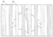
視認性のよい警告画像にするためには、まず警告画像に置き換える画素の配置を中心対称でなく、例えばデータ空間の中心O1から1画素目の中心O2を基準にする必要がある。この場合の基準線を、視域境界である斜線g1、g2に沿った斜線g3、g4として示している。このように、データ空間の使用領域を非対称な配置にしないと、画面中心を境に警告画像の連続性が失われる。さらに、これら基準線g3、g4から最近傍の画素を、各x座標(要素画像)につき一定の整数個選択するのではなく、各x座標につき基準線を中心に、非整数画素分の範囲にある画素だけを選択する。したがって、各x座標(各要素画像)ごとに、選択される画素数は異なり、要素画像の、表示部における水平位置によって、n(整数)視差相当分の幅の画素が選択される領域と、n+1視差相当分の幅の画素が選択される領域が、周期的になる。これによって、視認されやすい空間周波数の濃淡パターンが現れるようになる。非整数の値は例えば0.75や1.25などでもよいが、特に非整数の値を0.5や1.5のような非整数値(=整数+0.5)の値に設定すると、濃淡のパターンが等間隔となり、視認性が最もよくなる。図4は、非整数値が整数+0.5である範囲の画素を選択して黒のデータに置き換えた場合に、偽像の代わりに見える警告画像を示したものである。図4に示すC1が警告画像を入れない場合と同じように見える領域であり、C2が黒っぽく見える領域である。 In order to obtain a warning image with high visibility, first, it is necessary that the pixel arrangement replaced with the warning image is not center-symmetrical, for example, based on the center O 2 of the first pixel from the center O 1 of the data space. The reference lines in this case are shown as oblique lines g 3 and g 4 along the oblique lines g 1 and g 2 which are viewing zone boundaries. As described above, unless the use area of the data space is asymmetrically arranged, the continuity of the warning image is lost at the center of the screen. Furthermore, instead of selecting a fixed integer number of the nearest pixels from these reference lines g 3 and g 4 for each x coordinate (element image), a non-integer pixel portion is centered around the reference line for each x coordinate. Select only pixels in the range. Therefore, the number of pixels to be selected is different for each x coordinate (each element image), and an area in which a pixel having a width corresponding to n (integer) parallax is selected depending on the horizontal position of the element image in the display unit; A region in which pixels having a width corresponding to n + 1 parallax are selected is periodic. As a result, a light and shade pattern with a spatial frequency that is easy to visually recognize appears. The non-integer value may be, for example, 0.75 or 1.25, but when the non-integer value is set to a non-integer value (= integer + 0.5) such as 0.5 or 1.5, The shading pattern is equally spaced and the visibility is best. FIG. 4 shows a warning image that appears instead of a false image when a pixel in a range where the non-integer value is an integer +0.5 is selected and replaced with black data. C1 shown in FIG. 4 is an area that looks the same as when no warning image is inserted, and C2 is an area that looks dark.
また、図5は、ある一定数の画素行ごとに、非整数値を0.5と1.5に変えた場合の、偽像の代わりに見える警告画像を示したものである。すなわち、要素画像の表示部の垂直方向に、水平方向の第1の周期的パターンR1(非整数値が0.5)と、この第1の周期パターンとは異なる水平方向の第2の周期的パターンR2(非整数値が1.5)とが交互に現れる周期的パターンとなっている。C1が警告画像を入れない場合と同じように見える領域であり、C2が黒っぽく見える領域であり、C3はC2よりさらに黒っぽく見える領域である。図5に示すパターンは、横方向と縦方向のパターン周期をほぼ同じとしており、市松模様とは多少異なるパターンであるが、特に視認性がよい。非整数値は、視差数に対して小さいほど、警告画像により犠牲になる視域幅が少なくて済むため、0.5あるいは1.5が特に好ましく、それぞれ0視差相当幅と1視差相当幅の周期的パターン、あるいは、1視差相当幅と2視差相当幅の周期的パターンとなる。非整数であれば、小さい値であっても視認性は十分に得られ、大きい値にする必要は特にない。 FIG. 5 shows a warning image that appears in place of a false image when the non-integer value is changed to 0.5 and 1.5 for every certain number of pixel rows. That is, in the vertical direction of the display portion of the element image, the first periodic pattern R1 in the horizontal direction (non-integer value is 0.5) and the second periodic in the horizontal direction different from the first periodic pattern. It is a periodic pattern in which the pattern R2 (non-integer value is 1.5) appears alternately. C1 is an area that looks the same as when no warning image is inserted, C2 is an area that looks darker, and C3 is an area that looks darker than C2. The pattern shown in FIG. 5 has substantially the same pattern period in the horizontal direction and the vertical direction, and is a slightly different pattern from the checkered pattern, but has particularly good visibility. As the non-integer value is smaller with respect to the number of parallaxes, the visual field width sacrificed by the warning image may be smaller. Therefore, 0.5 or 1.5 is particularly preferable, and the width corresponding to 0 parallax and the width corresponding to 1 parallax are preferable. It becomes a periodic pattern or a periodic pattern having a width corresponding to one parallax and a width corresponding to two parallaxes. If it is a non-integer, even if it is a small value, sufficient visibility is obtained, and it is not particularly necessary to make it a large value.
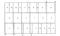
図6は、18視差30カメラの場合の各視差成分画像の使用範囲の形状の例を表している。図6に示す数字は各視差成分画像に対応する視差番号を表し、実線で示される領域が各視差成分画像の、3次元画像を表示するのに使用されるデータを表し、破線で示される領域が各視差成分画像の、3次元画像を表示するのに使用されないデータを表している。図1に示す12視差の例と同様、カメラごとに使用範囲が異なるが、視差数と同じ数だけ離れたカメラ番号の画像の使用範囲を合わせると、図7に示すように18枚の同じサイズの画像にまとめられる。例えば、(−9,10)、(−8,11)、(−7,12)、(−6,13)、(−5,14)、(−4,15)、(−15,4)、(−14,5)、(−13,6)、(−12,7)、(−11,8)、(−10,9)の組のカメラ番号の画像の使用範囲を合わせればよい。さらに図8に示すように1枚のフォーマットに連結して視差成分画像の全連結画像とすることができ、これは要素画像の表示部に表示する最終的な形式の画像と同じサイズである。以上のような視差成分画像の連結方法は、特許文献1に開示されている。また、図7に示すような視差数と同じ枚数の連結画像を重ね合わせて、y座標一定の面で切った断面が、図1に相当する。
FIG. 6 shows an example of the shape of the usage range of each parallax component image in the case of an 18-parallax 30 camera. The numbers shown in FIG. 6 represent the parallax numbers corresponding to the respective parallax component images, the area indicated by the solid line represents the data used to display the three-dimensional image of each parallax component image, and the area indicated by the broken line Represents data that is not used to display a three-dimensional image of each parallax component image. As in the example of 12 parallaxes shown in FIG. 1, the range of use differs for each camera, but when the range of use of images with camera numbers separated by the same number as the number of parallaxes is combined, as shown in FIG. The images are summarized. For example, (-9,10), (-8,11), (-7,12), (-6,13), (-5,14), (-4,15), (-15,4) , (−14, 5), (−13, 6), (−12, 7), (−11, 8), and (−10, 9) sets of camera number images may be combined. Furthermore, as shown in FIG. 8, it can be connected to one format to form all connected images of parallax component images, which is the same size as the final format image displayed on the element image display section. A method for connecting parallax component images as described above is disclosed in
したがって、警告画像表示を行わない通常の場合、図8に示す全連結画像のフォーマットから、1対1の画素変換により最終的な表示形式(視差合成画像、要素画像アレイ)に変換すればよいが、本実施形態のように、図4や図5に示すような警告画像表示を加えるためには、1対1の画素変換処理のうち、図1に示す基準線g3、g4から平均値が非整数値となる画素範囲にある一部の画素を変換しない処理にすれば、変換されない部分が黒となるため、自動的に警告画像が生成される。1対1の画素変換を、変換前後の画素の対応をまとめたマップ(変換テーブル)を使用して行っている場合は、通常表示時と警告画像表示時でマップを切り替える、あるいはマップの終端位置を変えるのみでよく、警告画像表示により処理負荷が増加することはない。 Therefore, in a normal case where warning image display is not performed, the format of all connected images shown in FIG. 8 may be converted into a final display format (parallax composite image, element image array) by one-to-one pixel conversion. In order to add a warning image display as shown in FIG. 4 or 5 as in the present embodiment, the average value is calculated from the reference lines g 3 and g 4 shown in FIG. If some pixels in the pixel range in which is a non-integer value are not converted, the non-converted portion is black, and a warning image is automatically generated. When one-to-one pixel conversion is performed using a map (conversion table) that summarizes the correspondence between pixels before and after conversion, the map is switched between normal display and warning image display, or the end position of the map It is only necessary to change the value, and the processing load is not increased by the warning image display.
図9に示すように、図8に示す全連結画像のフォーマットにおいて予め警告画像用の黒領域BLを入れ込んでおき、通常時と同じ1対1変換処理を行って警告画像表示する方法もあるが、図9に示す状態で非可逆圧縮・展開を行うと、図8に示す状態の場合に比べ、圧縮率低下や画質劣化が起こりやすくなる。したがって、タイリング形式のフォーマットにおいては、警告画像を入れないでおき、変換時の処理によって警告画像を入れることが望ましい。図9(a)は図4の場合、図9(b)は図5の場合にそれぞれ対応する。 As shown in FIG. 9, there is a method in which a warning image black region BL is inserted in advance in the format of all connected images shown in FIG. 8 and the warning image is displayed by performing the same one-to-one conversion processing as usual. However, if irreversible compression / decompression is performed in the state shown in FIG. 9, the compression rate and image quality are more likely to deteriorate than in the state shown in FIG. 8. Therefore, in the tiling format, it is desirable not to put a warning image and to put a warning image by a process at the time of conversion. 9A corresponds to the case of FIG. 4, and FIG. 9B corresponds to the case of FIG.
本実施形態の立体映像表示装置の光線制御素子の光学的開口は、垂直でなく斜めやジグザグや階段形状でもよく、また表示装置の画素配列がデルタ配列であってもよい。その場合においても、本実施形態で説明した表示方法のように、0視差相当幅と1視差相当幅の周期的パターン(非整数値=0.5)、あるいは、1視差相当幅と2視差相当幅の周期的パターン(非整数値=1.5)の単色部を用いることにより、警告画像表示が簡易な処理によって可能である。なお、単色部は、黒色に限らず、灰色、青色、黄色、赤色、紫色などでもよく、画像内容によって変化させてもよい。視差数が小さい条件では、画像と単色部のコントラストが高すぎると、視域中央でも薄く見えてしまうことがあるため、灰色が好ましい場合がある。単色部の色は、視域中央では画像内容によらず見えず、視域境界では画像内容によらず見えやすいことが望ましい。 The optical aperture of the light beam control element of the stereoscopic image display apparatus according to this embodiment may not be vertical but may be oblique, zigzag or stepped, and the pixel arrangement of the display apparatus may be a delta arrangement. Even in such a case, as in the display method described in this embodiment, a periodic pattern (non-integer value = 0.5) having a width corresponding to 0 parallax and a width corresponding to 1 parallax, or a width corresponding to 1 parallax and 2 parallax. By using a single color portion of a periodic pattern of width (non-integer value = 1.5), warning image display is possible by simple processing. The single color portion is not limited to black, but may be gray, blue, yellow, red, purple, or the like, and may be changed depending on the image content. Under conditions with a small number of parallaxes, if the contrast between the image and the monochromatic part is too high, the image may appear light even in the center of the viewing zone, so gray may be preferable. It is desirable that the color of the single color portion is not visible at the center of the viewing zone regardless of the image content and is easily visible at the border of the viewing zone regardless of the image content.
次に、IP方式の視差画像配置を用いた立体映像表示について図10(a)乃至図22を参照して説明する。図10(a)乃至図22に示す立体映像の表示は、図1乃至図9を参照して説明した本実施形態で説明した表示方法と組み合わせて実現される。ここでは18視差の場合の例に取って説明する。 Next, stereoscopic video display using an IP parallax image arrangement will be described with reference to FIGS. The stereoscopic video display shown in FIGS. 10A to 22 is realized in combination with the display method described in the present embodiment described with reference to FIGS. Here, an example in the case of 18 parallax will be described.
図10(a)は、光線制御素子としてのレンチキュラーシート334の斜視図であり、図10(b)は、光線制御素子としてのスリット333の斜視図である。図10(a)、10(b)において、Psは視差バリアピッチを示し、Ppは要素画像表示部の画素ピッチを示す。
10A is a perspective view of a
図11は、立体映像表示装置の概略の構成を示す図である。必要に応じ拡散シート301が要素画像表示部331とレンチキュラー板(光線制御素子)332の間に設けられている。想定視距離上の視点343から見ると、水平方向の視角341と垂直方向の視角342の範囲で立体映像が観察されるが、視差は水平方向のみである。図7や図8に示すような入力画像を入力する画像入力部380、および図1に関して説明したような方法により画素変換を行う画素変換部382を備えている。
FIG. 11 is a diagram illustrating a schematic configuration of a stereoscopic video display device. A
図12(a)、12(b)、12(c)は、図11に示した立体映像表示装置の表示部を基準にして垂直面内及び水平面内における光線再生範囲を概略的に示す展開図であり、図12(a)は要素画像表示部331、視差バリア332の正面図、図12(b)は立体映像表示装置の画像配置を示す平面図、図12(c)は立体映像表示装置の側面図を示す。図11乃至図12(c)に示すように、立体映像表示装置は、液晶表示素子などの平面画像表示部(要素画像表示部)331及び光学的開口を有する光線制御素子332を備えている。図10(a)、10(b)に示すような垂直方向に光学的開口が直線状に伸び水平方向に周期的に配列される形状のレンチュキュラーシート334或いはスリット333で構成され、投射型の場合は曲面鏡アレイなどで構成される。
12 (a), 12 (b), and 12 (c) are developed views schematically showing light beam reproduction ranges in a vertical plane and a horizontal plane with reference to the display unit of the stereoscopic image display apparatus shown in FIG. 12 (a) is a front view of the element
この立体映像表示装置においては、水平方向の視角341及び垂直方向の視角342の範囲内において、眼の位置343から視差バリア332を介して表示装置331を観察して要素画像表示部331の前面及び背面に立体像を観察することができる。ここでは、要素画像表示部331の画素数は、正方形となる最小単位の画素で数えた場合の一例として横方向(水平方向)が1920であり、縦方向(垂直方向)が1200であり、各最小単位の画素は、赤(R)、緑(G)、青(B)のサブ画素を含んでいるものとする。
In this stereoscopic image display device, the
図12(a)、12(b)、12(c)において、視差バリア332と視距離面343との間の視距離L、視差バリアピッチPs、視差バリア332と要素画像表示部331との間のギャップ(視差バリアギャップ)dが定められれば、要素画像のピッチPeが視距離面343上の視点からアパーチャ中心を表示素子上に投影した間隔により決定される。符号346は、視点位置と各アパーチャ中心とを結ぶ線を示し、視域幅Wは表示部331の表示面上で要素画像同士が重なり合わないという条件から決定される。
12A, 12B, and 12C, the viewing distance L between the
1次元IP方式にあっては、この直線346は、表示部331の表示面上では各サブ画素の中心を通るとは限らない。これに対し、多眼方式では、視点位置と各アパーチャの中心とを結ぶ線は、サブ画素中心を通り、光線軌跡に一致している。アパーチャの水平ピッチPsがサブ画素ピッチPpの整数倍の場合では、要素画像のピッチPeは、サブ画素ピッチPpの整数倍から大きめにずれた端数を伴っている。アパーチャの水平ピッチPsがサブ画素ピッチPpの整数倍でなくても、一般的に1次元IPでは、要素画像のピッチPeは、サブ画素ピッチPpの整数倍からずれた端数を伴うこととなる。これに対し多眼では要素画像のピッチPeはサブ画素ピッチPpの整数倍となる。
In the one-dimensional IP method, the
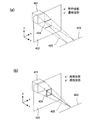
図13(a)、13(b)は、本発明の一実施形態における1次元IP方式の視差成分画像と立体画像の構成方法を示している。表示される物体(被写体)421は、実際に立体映像表示装置の光線制御素子が置かれる面と同じ位置にある投影面422に投影される。歪のない立体像を得るためには、図13(a)に示すように、垂直方向が透視投影、水平方向が平行投影になるように、投影面と平行で正面(上下方向の中央)にありかつ視距離面内にある投影中心線423に向かう投影線425に沿って投影される。投影線425は、垂直方向は投影中心線423において交わるが、水平方向は交わらず平行である。この投影法により、投影面422上に投影された被写体の像424が作成される。立体感を多少強調するような歪を立体像に入れる場合には、図13(b)に示すように、通常の透視投影になるように、投影面422と平行で正面(上下方向の中央)にありかつ視距離面内にある投影中心線423上の一点(カメラ位置)に向かう投影線425に沿って投影される。この投影法により、投影面422上に、透視投影された被写体の像424が作成される。なお、通常の透視投影しか使えないときに、立体像の歪を抑制する必要性が高い場合は、CGモデルを変形させた上でこの投影法を用いればよい。z方向(奥行き方向)に反比例して、飛び出し領域のx方向を縮小、奥行き領域のx方向を拡大する変形方法となる。
FIGS. 13A and 13B show a method for constructing a one-dimensional IP parallax component image and a stereoscopic image according to an embodiment of the present invention. The displayed object (subject) 421 is projected onto the
投影方向は、視距離により数10方向が必要である。視距離1000mmの平行光線1次元IPの場合、要素画像幅は18.036サブ画素幅となった。この場合、カメラ数は30である。投影された画像(視差成分画像)は、それぞれ必要な範囲の列のみ作成すればよく、必要な範囲は、図6および図14に示されている。各投影方向は視差番号(カメラ番号)に対応するが、各方向は等角度ではなく、視距離面上で等間隔になるようにする。すなわちカメラを投影中心線上で等間隔に平行移動(向きは一定)して撮影することに相当する。 The projection direction needs several tens directions depending on the viewing distance. In the case of a parallel light one-dimensional IP with a viewing distance of 1000 mm, the element image width was 18.036 subpixel width. In this case, the number of cameras is 30. The projected image (parallax component image) only needs to be created for each necessary range column, and the necessary range is shown in FIGS. 6 and 14. Each projection direction corresponds to a parallax number (camera number), but each direction is not equiangular, but equidistant on the viewing distance plane. In other words, this corresponds to photographing with the camera moved parallel at equal intervals on the projection center line (the direction is constant).
図15は、立体映像表示方法における撮像の概略を示している。等間隔に水平方向に並べられたカメラ429は投影面422に対し撮像されるように調整される。符号421は表示される物体(被写体)を示す。Lは視距離を示し、Pはカメラ429のピッチを示し、Znは飛び出し側の立体映像表示可能範囲を示し、Zfは奥行き側の立体映像表示可能範囲を示す。投影面422上に透視投影された各方向分の画像(視差成分画像)は、図6に示すように、投影面の範囲のうち使用される範囲がまちまちであるが、図7の連結画像群あるいは図8に示す全連結画像に前述のようにまとめられる。図16には、この形式からの変換方法が示されている。視域の右端のカメラ画像(#−9)を含む連結画像を、視差合成画像の左端1列目から、18サブ画素おきに、サブ画素を縦に並べ替えながら右端まで配置し、視域の右端から2番目のカメラ画像(#−8)を含む連結画像を、視差合成画像の左端2列目から、18サブ画素おきに、サブ画素を縦に並べ替えながら右端まで配置する。これを以下同様に繰り返し、最後に視域の左端のカメラ画像(#9)を含む連結画像を含む連結画像を、視差合成画像の左端18列目から、18サブ画素おきに、サブ画素を縦に並べ替えながら、右端まで配置する。以上のような1対1変換処理により、要素画像表示面の視差合成画像全体が完成する。
FIG. 15 shows an outline of imaging in the stereoscopic video display method. The
図17に、本実施形態の立体映像表示装置の一部分の構成を概略的に示す。液晶パネルなどの平面状の要素画像表示部の表示面の前面に、光線制御素子として光学開口が垂直方向に延びるシリンドリカルレンズからなるレンチキュラーシート334が配置されている。なお光学開口は斜めや階段状であってもよい。表示面には、縦横比が3:1のサブ画素34が、横方向および縦方向にそれぞれ直線状にマトリクス状に並び、各サブ画素は同一行および列内で横方向に赤、緑、青が交互に並ぶように配列されている。この色配列は一般にモザイク配列と呼ばれる。
FIG. 17 schematically shows a partial configuration of the stereoscopic video display apparatus according to the present embodiment. A
図18に、画素配列の平面図の例を示す。−9から9までの数字は、視差番号を表しており、隣接視差番号は隣接列に割当てられている。サブ画素行の縦周期は、サブ画素の横周期Ppの3倍である。図18に示される表示画面では、18列6行のサブ画素34で1実効画素43(この1実効画素43は、図17において黒枠で示されている)あるいは18列3行のサブ画素で1実効画素が構成される。このような表示部の構造では、水平方向に18視差を与える立体映像表示が可能となる。この表示構造では、多眼式の場合は18眼となり、要素画像ピッチが18サブ画素ピッチであり、かつ光線制御素子の横ピッチが18サブ画素ピッチより小さくなる。
FIG. 18 shows an example of a plan view of a pixel array. The numbers from -9 to 9 represent parallax numbers, and the adjacent parallax numbers are assigned to the adjacent columns. The vertical period of the sub-pixel row is three times the horizontal period Pp of the sub-pixel. In the display screen shown in FIG. 18, one
IP方式の場合は、例えば18サブ画素ピッチが視差バリアピッチPsに等しく平行光線の組ができるような設計においては18サブ画素幅よりわずかに大きい間隔(例えば18.036)で要素画像境界が生じることから、実効画素の幅は、表示面内の位置により18列分或いは19列分となる。すなわち、要素画像ピッチの平均値が18サブ画素幅より大きく、かつ光線制御素子の横ピッチが18サブ画素幅である。実効画素の幅が19列分の場合の例を図19に示す。 In the case of the IP system, for example, in a design in which the 18 sub-pixel pitch is equal to the parallax barrier pitch Ps and a pair of parallel rays can be formed, element image boundaries are generated at intervals slightly larger than the 18 sub-pixel width (for example, 18.036). Therefore, the effective pixel width is 18 columns or 19 columns depending on the position in the display surface. That is, the average value of the element image pitch is larger than the 18 sub-pixel width, and the horizontal pitch of the light beam control elements is 18 sub-pixel width. FIG. 19 shows an example in which the effective pixel width is 19 columns.
図20或いは図21に、立体映像表示装置の表示部の水平断面を概略的に示す。ここに示すようにスリット333又はレンチキュラーシート334のレンチキュラーレンズの水平方向のピッチPs(周期)は、整数サブ画素幅に定められている。即ち、各スリット332間の中心を通る中心軸351又は隣接するレンチキュラーレンズの境界を通る基準軸352は、サブ画素境界を通る。中心軸351或いは基準軸352間に相当する領域には、整数個のサブ画素335が配置され、中心軸351或いは基準軸352の水平方向のピッチPs(周期)は、一定に定められている。ここに示す例では、このピッチPsは、18サブ画素幅に定められている。要素画像表示部の表示面331と視差バリア332、334との間の視差バリアギャップdは、ガラス基板或いはレンズ材質の屈折率を考慮して実効的に約2mmに定められている。なお、符号343は視距離面を示し、符号363は視差成分画像の番号を示す。
FIG. 20 or FIG. 21 schematically shows a horizontal section of the display unit of the stereoscopic video display device. As shown here, the horizontal pitch Ps (cycle) of the
図22は、本発明の一実施形態によるIP方式における立体映像表示装置の要素画像表示部の表示面内における画像の配置方法を、表示部を正面から見た概念図として示している。要素画像表示部の表示面は、各アパーチャ(光線制御素子の開口部)に対応する要素画像370に分けられ、要素画像370は、IP方式においてそれぞれ18列又は19列のサブ画素列365から構成されている。視差割り当て可能なサブ画素列の合計数は5760列、アパーチャ数は320(図22において、アパーチャ番号を示す領域364の範囲は、#−160〜#−1、#1〜#160)であり、アパーチャピッチPsは、18サブ画素幅と等しい。図22において、各サブ画素列365には、対応する視差番号を示す領域363(この例では、視差番号−15〜−1、1〜15の30方向分)が示されている。アパーチャ番号#1の要素画像370は、視差番号−9〜−1、1〜9の18視差の列からなり、アパーチャ番号#−159の要素画像は、視差番号−15〜−1、1〜3の18視差の列からなる。要素画像370の幅が18サブ画素列の幅よりわずかに大きいため、要素画像370の境界を最も近いサブ画素列境界に合わせる(通常のA−D変換方法)とすると、アパーチャに対するサブ画素列数は、大部分のアパーチャにおいて18列であるが、19列になっているアパーチャも出てくる(図18および図19参照)。19列になるアパーチャ番号を境に、アパーチャ内の視差番号範囲が1つずつシフトされている。19列になっているアパーチャ番号は、#14、#42、#70、#98、#125、#153(及びそのマイナスの番号)である(視距離1000mmの場合)。
FIG. 22 is a conceptual diagram showing a display unit viewed from the front, with respect to an image arrangement method in a display surface of an element image display unit of a stereoscopic video display device in an IP system according to an embodiment of the present invention. The display surface of the element image display unit is divided into
図14において、各方向の視差画像の配置が開始・終了されるレンズ番号(表中3D画素番号)が示されている。この表には、対応する要素画像表示部(液晶パネル)のサブ画素列番号も示されている。 FIG. 14 shows the lens numbers (3D pixel numbers in the table) at which the arrangement of parallax images in each direction starts and ends. This table also shows the sub pixel column numbers of the corresponding element image display section (liquid crystal panel).
以上のように、本発明の一実施形態によれば、1次元IP方式において、処理負荷・視域を犠牲にせず、簡易に偽像抑制(視認性のよい警告画像表示)が可能となる。 As described above, according to an embodiment of the present invention, in the one-dimensional IP method, it is possible to easily suppress false images (display warning images with high visibility) without sacrificing the processing load and viewing area.
尚、この発明は、上記実施形態そのままに限定されるものでなく、実施段階では、その要旨を逸脱しない範囲で構成要素を変形して具体化できる。 In addition, this invention is not limited to the said embodiment as it is, In an implementation stage, a component can be deform | transformed and embodied in the range which does not deviate from the summary.
また、上記実施形態に開示されている複数の構成要素の適宜な組合せにより種々の発明を形成できる。例えば、実施形態に示される全構成要素からいくつかの構成要素を削除してもよい。更に、異なる実施形態に亘る構成要素を適宜組み合わせてもよい。 Moreover, various inventions can be formed by appropriately combining a plurality of constituent elements disclosed in the embodiment. For example, some components may be deleted from all the components shown in the embodiment. Furthermore, you may combine the component covering different embodiment suitably.
34 サブ画素
43 立体映像表示時の実効画素
301 拡散シート
331 要素画像表示部(平面画像表示部)
332 視差バリア
333 スリット
334 レンチキュラー板
335 サブ画素
341 水平方向の視角
342 垂直方向の視角
343 視距離面
346 視点とアパーチャ中心を結ぶ線
363 視差成分画像の番号
364 アパーチャの番号
365 要素画像表示部のサブ画素列
370 要素画像
421 表示される物体(被写体)
422 投影面
423 投影中心線
424 投影面上に投影された被写体
425 投影線
429 カメラ
34 Sub-pixel 43
332
422
Claims (12)
前記要素画像表示部に対向して設置され、略垂直方向に直線状に延びるとともに略水平方向に周期的に並びそれぞれが各要素画像に関連付けられた複数の光学的開口部を有し、前記要素画像表示部からの光線を制御する光線制御素子と、
仮想的なカメラによるカメラ画像の座標を示す第1の軸と、前記カメラの番号を示す第2の軸で表されたデータ空間において、前記要素画像の境界線と平行であって前記第1の軸の中心から前記第1の軸方向にずれている基準線を中心に、非整数画素分の範囲にある画素を選択し、前記選択された画素を警告画像に置き換える画像データ変換部と、
を備えたことを特徴とする立体映像表示装置。 An element image display unit configured to display a plurality of element images each including a plurality of parallax component images, in which pixels are arranged in a matrix in the display surface;
The plurality of optical openings that are installed opposite to the element image display section, extend linearly in a substantially vertical direction, and are periodically arranged in a substantially horizontal direction, each associated with each element image, A light beam control element for controlling the light beam from the image display unit;
In the data space represented by the first axis indicating the coordinates of the camera image by the virtual camera and the second axis indicating the camera number, the first space is parallel to the boundary line of the element image, and An image data conversion unit that selects pixels within a range of non-integer pixels around a reference line that is shifted from the center of the axis in the first axis direction, and replaces the selected pixels with a warning image ;
A stereoscopic video display device comprising:
仮想的なカメラによるカメラ画像の座標を示す第1の軸と、前記カメラの番号を示す第2の軸で表されたデータ空間において、前記要素画像の境界線と平行であって前記第1の軸の中心から前記第1の軸方向にずれている基準線を中心に、非整数画素分の範囲にある画素を選択し、前記選択された画素を警告画像に置き換えるステップを備えたことを特徴とする立体映像表示方法。 Pixels are arranged in a matrix form within the display surface, each of which is installed facing an element image display unit that displays a plurality of element images each including a plurality of parallax component images. A light beam control element that extends in a straight line and is periodically arranged in a substantially horizontal direction, each of which has a plurality of optical apertures associated with each element image, and controls a light beam from the element image display section. A stereoscopic video display method for displaying stereoscopic video using a stereoscopic video display device,
In the data space represented by the first axis indicating the coordinates of the camera image by the virtual camera and the second axis indicating the camera number, the first space is parallel to the boundary line of the element image, and Selecting a pixel in a range of non-integer pixels centering on a reference line that is shifted in the first axial direction from the center of the axis, and replacing the selected pixel with a warning image. 3D video display method.
Priority Applications (6)
| Application Number | Priority Date | Filing Date | Title |
|---|---|---|---|
| JP2006243255A JP4714115B2 (en) | 2006-09-07 | 2006-09-07 | 3D image display apparatus and 3D image display method |
| KR1020097002828A KR20090031767A (en) | 2006-09-07 | 2007-08-31 | Three-dimensional image display device and three-dimensional image display method |
| CNA2007800292845A CN101507287A (en) | 2006-09-07 | 2007-08-31 | Three-dimensional image display device and three-dimensional image display method |
| PCT/JP2007/067543 WO2008029930A1 (en) | 2006-09-07 | 2007-08-31 | Three-dimensional image display device and three-dimensional image display method |
| US11/887,917 US8384772B2 (en) | 2006-09-07 | 2007-08-31 | Three-dimensional image display device and three-dimensional image display method |
| EP07806975A EP2062445A1 (en) | 2006-09-07 | 2007-08-31 | Three-dimensional image display device and three-dimensional image display method |
Applications Claiming Priority (1)
| Application Number | Priority Date | Filing Date | Title |
|---|---|---|---|
| JP2006243255A JP4714115B2 (en) | 2006-09-07 | 2006-09-07 | 3D image display apparatus and 3D image display method |
Publications (3)
| Publication Number | Publication Date |
|---|---|
| JP2008067092A JP2008067092A (en) | 2008-03-21 |
| JP2008067092A5 JP2008067092A5 (en) | 2008-08-14 |
| JP4714115B2 true JP4714115B2 (en) | 2011-06-29 |
Family
ID=38895915
Family Applications (1)
| Application Number | Title | Priority Date | Filing Date |
|---|---|---|---|
| JP2006243255A Expired - Fee Related JP4714115B2 (en) | 2006-09-07 | 2006-09-07 | 3D image display apparatus and 3D image display method |
Country Status (6)
| Country | Link |
|---|---|
| US (1) | US8384772B2 (en) |
| EP (1) | EP2062445A1 (en) |
| JP (1) | JP4714115B2 (en) |
| KR (1) | KR20090031767A (en) |
| CN (1) | CN101507287A (en) |
| WO (1) | WO2008029930A1 (en) |
Families Citing this family (19)
| Publication number | Priority date | Publication date | Assignee | Title |
|---|---|---|---|---|
| JP5152718B2 (en) * | 2007-12-26 | 2013-02-27 | Nltテクノロジー株式会社 | Image display device and terminal device |
| JP5514219B2 (en) * | 2008-10-28 | 2014-06-04 | コーニンクレッカ フィリップス エヌ ヴェ | 3D display system |
| US9083965B2 (en) * | 2009-05-22 | 2015-07-14 | Sharp Kabushiki Kaisha | Stereoscopic display device |
| JP5796761B2 (en) * | 2010-09-15 | 2015-10-21 | Nltテクノロジー株式会社 | Image display device and display panel |
| KR101716144B1 (en) * | 2010-09-20 | 2017-03-14 | 엘지전자 주식회사 | Image display apparatus, and method for operating the same |
| JP5269027B2 (en) | 2010-09-30 | 2013-08-21 | 株式会社東芝 | Three-dimensional image display device and image processing device |
| US20130044372A1 (en) * | 2011-08-18 | 2013-02-21 | 3Dv Co. Ltd. | Arrangement of color sub-pixels in an image display panel for 2d/3d display |
| JP5050120B1 (en) * | 2011-08-31 | 2012-10-17 | 株式会社東芝 | Stereoscopic image display device |
| KR20130080517A (en) | 2012-01-05 | 2013-07-15 | 삼성디스플레이 주식회사 | Method of displaying stereoscopic image and display apparatus performing for the method |
| KR101306245B1 (en) | 2012-01-17 | 2013-09-09 | 한국과학기술연구원 | 3-dimensional display apparatus using time division scheme |
| CN102630027B (en) * | 2012-02-21 | 2015-04-08 | 京东方科技集团股份有限公司 | Naked eye 3D display method and apparatus thereof |
| JP5343157B2 (en) * | 2012-07-13 | 2013-11-13 | 株式会社東芝 | Stereoscopic image display device, display method, and test pattern |
| CN104597610B (en) * | 2015-02-10 | 2016-12-07 | 京东方科技集团股份有限公司 | The display processing method of a kind of bore hole 3D, device and display device |
| CN106249425A (en) * | 2016-08-19 | 2016-12-21 | 深圳市谛源光科有限公司 | A kind of high accuracy bore hole 3D para-position applying system and method |
| CN106249424B (en) * | 2016-08-19 | 2019-01-18 | 深圳市谛源光科有限公司 | A kind of high-precision naked eye 3D contraposition applying method |
| KR102547821B1 (en) * | 2016-11-25 | 2023-06-26 | 삼성전자주식회사 | 3d display apparatus |
| WO2019058307A1 (en) * | 2017-09-20 | 2019-03-28 | Imax Theatres International Limited | Light emitting display with tiles and data processing |
| CN108121079A (en) * | 2017-12-08 | 2018-06-05 | 朱晨乐 | Bore hole 3D display screen pixel arrangement structure and aligning method |
| CN109870108B (en) * | 2019-02-28 | 2020-09-11 | 北京国网富达科技发展有限责任公司 | Method and device for detecting icing of power transmission line |
Citations (2)
| Publication number | Priority date | Publication date | Assignee | Title |
|---|---|---|---|---|
| JP2004258210A (en) * | 2003-02-25 | 2004-09-16 | Toshiba Corp | Three-dimensional picture display device and picture display method |
| JP2004295013A (en) * | 2003-03-28 | 2004-10-21 | Toshiba Corp | Stereoscopic display device |
Family Cites Families (15)
| Publication number | Priority date | Publication date | Assignee | Title |
|---|---|---|---|---|
| US7002749B2 (en) * | 1997-07-08 | 2006-02-21 | Kremen Stanley H | Modular integral magnifier |
| WO2002051165A1 (en) * | 2000-12-18 | 2002-06-27 | Lee Byoung-Ho | Relfecting three-dimensional display system |
| KR100430381B1 (en) * | 2001-08-30 | 2004-05-04 | 병 호 이 | Three-dimensional display |
| US7425951B2 (en) * | 2002-12-27 | 2008-09-16 | Kabushiki Kaisha Toshiba | Three-dimensional image display apparatus, method of distributing elemental images to the display apparatus, and method of displaying three-dimensional image on the display apparatus |
| JP2005110010A (en) * | 2003-09-30 | 2005-04-21 | Toshiba Corp | Method for generating stereoscopic image and device for displaying stereoscopic image |
| JP4271155B2 (en) * | 2004-02-10 | 2009-06-03 | 株式会社東芝 | 3D image display device |
| JP4015124B2 (en) * | 2004-03-03 | 2007-11-28 | 株式会社東芝 | 3D image display device |
| JP3944188B2 (en) * | 2004-05-21 | 2007-07-11 | 株式会社東芝 | Stereo image display method, stereo image imaging method, and stereo image display apparatus |
| JP4202991B2 (en) | 2004-09-29 | 2008-12-24 | 株式会社東芝 | Stereo image data recording method and display reproduction method |
| US20080252971A1 (en) * | 2005-03-02 | 2008-10-16 | Seoul National University Industry Foundation | Three-Dimensional/Two-Dimensional Convertible Display Device |
| JP4327758B2 (en) * | 2005-03-24 | 2009-09-09 | 株式会社東芝 | Stereoscopic image display device |
| JP4331134B2 (en) * | 2005-03-25 | 2009-09-16 | 株式会社東芝 | Stereoscopic image display device |
| US20060215018A1 (en) * | 2005-03-28 | 2006-09-28 | Rieko Fukushima | Image display apparatus |
| JP4476905B2 (en) | 2005-08-31 | 2010-06-09 | 株式会社東芝 | Structure of stereoscopic display image data, recording method of stereoscopic display image data, display reproduction method, recording program, and display reproduction program |
| US7742046B2 (en) * | 2005-08-31 | 2010-06-22 | Kabushiki Kaisha Toshiba | Method, device, and program for producing elemental image array for three-dimensional image display |
-
2006
- 2006-09-07 JP JP2006243255A patent/JP4714115B2/en not_active Expired - Fee Related
-
2007
- 2007-08-31 WO PCT/JP2007/067543 patent/WO2008029930A1/en active Application Filing
- 2007-08-31 US US11/887,917 patent/US8384772B2/en not_active Expired - Fee Related
- 2007-08-31 KR KR1020097002828A patent/KR20090031767A/en not_active Application Discontinuation
- 2007-08-31 EP EP07806975A patent/EP2062445A1/en not_active Withdrawn
- 2007-08-31 CN CNA2007800292845A patent/CN101507287A/en active Pending
Patent Citations (2)
| Publication number | Priority date | Publication date | Assignee | Title |
|---|---|---|---|---|
| JP2004258210A (en) * | 2003-02-25 | 2004-09-16 | Toshiba Corp | Three-dimensional picture display device and picture display method |
| JP2004295013A (en) * | 2003-03-28 | 2004-10-21 | Toshiba Corp | Stereoscopic display device |
Also Published As
| Publication number | Publication date |
|---|---|
| JP2008067092A (en) | 2008-03-21 |
| WO2008029930A1 (en) | 2008-03-13 |
| US8384772B2 (en) | 2013-02-26 |
| CN101507287A (en) | 2009-08-12 |
| KR20090031767A (en) | 2009-03-27 |
| EP2062445A1 (en) | 2009-05-27 |
| US20090309873A1 (en) | 2009-12-17 |
Similar Documents
| Publication | Publication Date | Title |
|---|---|---|
| JP4714115B2 (en) | 3D image display apparatus and 3D image display method | |
| JP4714116B2 (en) | 3D image display apparatus and 3D image display method | |
| JP3966830B2 (en) | 3D display device | |
| US7834903B2 (en) | Stereoscopic display device and display method | |
| JP4327758B2 (en) | Stereoscopic image display device | |
| JP5351129B2 (en) | Oblique direction parallax barrier type stereoscopic image display device | |
| JP5772688B2 (en) | Autostereoscopic display device | |
| US20080225113A1 (en) | Three-dimensional image display device, method for displaying three-dimensional image, and structure of three-dimensional image data | |
| JP5556557B2 (en) | Autostereoscopic display device | |
| JP2009080144A (en) | Stereoscopic image display apparatus and stereoscopic image display method | |
| KR20040049823A (en) | Multiple view display | |
| US20050083400A1 (en) | Three-dimensional image display device, three-dimensional image display method and three-dimensional display image data generating method | |
| CN111323935A (en) | N-viewpoint three-dimensional display device and driving method thereof | |
| US20120098827A1 (en) | Three-dimensional image display apparatus | |
| JP2012212079A (en) | Display device | |
| JP4393496B2 (en) | 3D image display device | |
| US11729368B2 (en) | Autostereoscopic display | |
| JP4119409B2 (en) | 3D image display apparatus, 3D image display method, and 3D display image data generation method | |
| JP2006174258A (en) | Program, stereoscopic image producing device, and stereoscopic image displaying device | |
| JP2004191570A (en) | Three-dimensional image display device | |
| KR101590770B1 (en) | Directional display apparatus without color moire and method thereof | |
| JP2006330744A (en) | Three-dimensional image display apparatus | |
| JP7445627B2 (en) | 3D display device | |
| JP2013007903A (en) | High-luminance stereoscopic display device and multi-display type high-luminance stereoscopic display device |
Legal Events
| Date | Code | Title | Description |
|---|---|---|---|
| A621 | Written request for application examination |
Free format text: JAPANESE INTERMEDIATE CODE: A621 Effective date: 20080326 |
|
| A521 | Request for written amendment filed |
Free format text: JAPANESE INTERMEDIATE CODE: A523 Effective date: 20080701 |
|
| A977 | Report on retrieval |
Free format text: JAPANESE INTERMEDIATE CODE: A971007 Effective date: 20101102 |
|
| A131 | Notification of reasons for refusal |
Free format text: JAPANESE INTERMEDIATE CODE: A131 Effective date: 20101217 |
|
| A521 | Request for written amendment filed |
Free format text: JAPANESE INTERMEDIATE CODE: A523 Effective date: 20110210 |
|
| A01 | Written decision to grant a patent or to grant a registration (utility model) |
Free format text: JAPANESE INTERMEDIATE CODE: A01 Effective date: 20110301 |
|
| A61 | First payment of annual fees (during grant procedure) |
Free format text: JAPANESE INTERMEDIATE CODE: A61 Effective date: 20110325 |
|
| FPAY | Renewal fee payment (event date is renewal date of database) |
Free format text: PAYMENT UNTIL: 20140401 Year of fee payment: 3 |
|
| LAPS | Cancellation because of no payment of annual fees |