JP4682102B2 - Image coding apparatus and image coding method - Google Patents
Image coding apparatus and image coding method Download PDFInfo
- Publication number
- JP4682102B2 JP4682102B2 JP2006197372A JP2006197372A JP4682102B2 JP 4682102 B2 JP4682102 B2 JP 4682102B2 JP 2006197372 A JP2006197372 A JP 2006197372A JP 2006197372 A JP2006197372 A JP 2006197372A JP 4682102 B2 JP4682102 B2 JP 4682102B2
- Authority
- JP
- Japan
- Prior art keywords
- encoding
- image
- compression
- data
- image data
- Prior art date
- Legal status (The legal status is an assumption and is not a legal conclusion. Google has not performed a legal analysis and makes no representation as to the accuracy of the status listed.)
- Expired - Fee Related
Links
Images


Classifications
-
- H—ELECTRICITY
- H04—ELECTRIC COMMUNICATION TECHNIQUE
- H04N—PICTORIAL COMMUNICATION, e.g. TELEVISION
- H04N19/00—Methods or arrangements for coding, decoding, compressing or decompressing digital video signals
- H04N19/50—Methods or arrangements for coding, decoding, compressing or decompressing digital video signals using predictive coding
- H04N19/59—Methods or arrangements for coding, decoding, compressing or decompressing digital video signals using predictive coding involving spatial sub-sampling or interpolation, e.g. alteration of picture size or resolution
-
- H—ELECTRICITY
- H04—ELECTRIC COMMUNICATION TECHNIQUE
- H04N—PICTORIAL COMMUNICATION, e.g. TELEVISION
- H04N19/00—Methods or arrangements for coding, decoding, compressing or decompressing digital video signals
- H04N19/10—Methods or arrangements for coding, decoding, compressing or decompressing digital video signals using adaptive coding
- H04N19/102—Methods or arrangements for coding, decoding, compressing or decompressing digital video signals using adaptive coding characterised by the element, parameter or selection affected or controlled by the adaptive coding
- H04N19/124—Quantisation
- H04N19/126—Details of normalisation or weighting functions, e.g. normalisation matrices or variable uniform quantisers
-
- H—ELECTRICITY
- H04—ELECTRIC COMMUNICATION TECHNIQUE
- H04N—PICTORIAL COMMUNICATION, e.g. TELEVISION
- H04N19/00—Methods or arrangements for coding, decoding, compressing or decompressing digital video signals
- H04N19/10—Methods or arrangements for coding, decoding, compressing or decompressing digital video signals using adaptive coding
- H04N19/102—Methods or arrangements for coding, decoding, compressing or decompressing digital video signals using adaptive coding characterised by the element, parameter or selection affected or controlled by the adaptive coding
- H04N19/13—Adaptive entropy coding, e.g. adaptive variable length coding [AVLC] or context adaptive binary arithmetic coding [CABAC]
-
- H—ELECTRICITY
- H04—ELECTRIC COMMUNICATION TECHNIQUE
- H04N—PICTORIAL COMMUNICATION, e.g. TELEVISION
- H04N19/00—Methods or arrangements for coding, decoding, compressing or decompressing digital video signals
- H04N19/10—Methods or arrangements for coding, decoding, compressing or decompressing digital video signals using adaptive coding
- H04N19/134—Methods or arrangements for coding, decoding, compressing or decompressing digital video signals using adaptive coding characterised by the element, parameter or criterion affecting or controlling the adaptive coding
- H04N19/146—Data rate or code amount at the encoder output
- H04N19/15—Data rate or code amount at the encoder output by monitoring actual compressed data size at the memory before deciding storage at the transmission buffer
-
- H—ELECTRICITY
- H04—ELECTRIC COMMUNICATION TECHNIQUE
- H04N—PICTORIAL COMMUNICATION, e.g. TELEVISION
- H04N19/00—Methods or arrangements for coding, decoding, compressing or decompressing digital video signals
- H04N19/10—Methods or arrangements for coding, decoding, compressing or decompressing digital video signals using adaptive coding
- H04N19/134—Methods or arrangements for coding, decoding, compressing or decompressing digital video signals using adaptive coding characterised by the element, parameter or criterion affecting or controlling the adaptive coding
- H04N19/154—Measured or subjectively estimated visual quality after decoding, e.g. measurement of distortion
-
- H—ELECTRICITY
- H04—ELECTRIC COMMUNICATION TECHNIQUE
- H04N—PICTORIAL COMMUNICATION, e.g. TELEVISION
- H04N19/00—Methods or arrangements for coding, decoding, compressing or decompressing digital video signals
- H04N19/10—Methods or arrangements for coding, decoding, compressing or decompressing digital video signals using adaptive coding
- H04N19/169—Methods or arrangements for coding, decoding, compressing or decompressing digital video signals using adaptive coding characterised by the coding unit, i.e. the structural portion or semantic portion of the video signal being the object or the subject of the adaptive coding
- H04N19/17—Methods or arrangements for coding, decoding, compressing or decompressing digital video signals using adaptive coding characterised by the coding unit, i.e. the structural portion or semantic portion of the video signal being the object or the subject of the adaptive coding the unit being an image region, e.g. an object
- H04N19/172—Methods or arrangements for coding, decoding, compressing or decompressing digital video signals using adaptive coding characterised by the coding unit, i.e. the structural portion or semantic portion of the video signal being the object or the subject of the adaptive coding the unit being an image region, e.g. an object the region being a picture, frame or field
-
- H—ELECTRICITY
- H04—ELECTRIC COMMUNICATION TECHNIQUE
- H04N—PICTORIAL COMMUNICATION, e.g. TELEVISION
- H04N19/00—Methods or arrangements for coding, decoding, compressing or decompressing digital video signals
- H04N19/42—Methods or arrangements for coding, decoding, compressing or decompressing digital video signals characterised by implementation details or hardware specially adapted for video compression or decompression, e.g. dedicated software implementation
- H04N19/423—Methods or arrangements for coding, decoding, compressing or decompressing digital video signals characterised by implementation details or hardware specially adapted for video compression or decompression, e.g. dedicated software implementation characterised by memory arrangements
Description
本発明は、画像データを符号化し、記録媒体に記録する、画像符号化装置及び画像符号化方法に関するものである。 The present invention relates to an image encoding apparatus and an image encoding method for encoding image data and recording the image data on a recording medium.
電子カメラ等の画像処理装置において撮像素子によって取得された画像データは、デジタルデータにA/D変換され、多くの場合は必要な画像処理を行った後にJPEG符号化等の非可逆圧縮変換を施され、JPEG画像データとして記録媒体に格納される。これにより、記憶容量が限られている記録媒体に、多くの画像データを効率的に格納することが可能になる。 Image data acquired by an image sensor in an image processing apparatus such as an electronic camera is A / D converted into digital data, and in many cases, after necessary image processing, irreversible compression conversion such as JPEG encoding is performed. And stored in the recording medium as JPEG image data. This makes it possible to efficiently store a large amount of image data on a recording medium with a limited storage capacity.
一方、より画像品質を重視したい場合においては、電子カメラ等の画像処理装置内部では一切の画像処理を行うことなく、撮像素子から得られる全ての情報(以下、「CCD−RAWデータ」とも呼ぶ)に可逆圧縮変換を施して記録媒体に記録する。そして、記録された画像データ(以下、「圧縮RAWデータ」とも呼ぶ)に対して、電子カメラのメーカ等が提供するコンピュータソフトウェア等により、より高品位な画像処理を行うことで、ユーザは、画像品質のより優れた画像を得ることができる。このような場合は、圧縮RAWデータの1つ1つに対応させてJPEG画像データを同時に記録することで、ユーザが撮影現場で記録画像を確認したり、そのまま記録画像としてデータ保存やプリントアウトしたりできるようになっている。 On the other hand, when the image quality is more important, all information obtained from the image sensor (hereinafter also referred to as “CCD-RAW data”) without performing any image processing inside the image processing apparatus such as an electronic camera. Is subjected to lossless compression conversion and recorded on a recording medium. The recorded image data (hereinafter also referred to as “compressed RAW data”) is subjected to higher quality image processing by computer software provided by the manufacturer of the electronic camera, etc. Images with better quality can be obtained. In such a case, by recording JPEG image data corresponding to each compressed RAW data at the same time, the user can check the recorded image at the shooting site, or save and print out the recorded image as it is. You can also.
電子カメラは、CCD−RAWデータから圧縮RAWデータやJPEG画像データを生成するために、種々の符号化パラメータに基づいてCCD−RAWデータを符号化する。符号化パラメータは、例えば、電子カメラがハフマン符号化のために使用するハフマンテーブルの種類や、量子化のために使用する量子化テーブルの種類などを示す。使用される符号化パラメータの種類によって、圧縮RAWデータやJPEG画像データの圧縮率は変化する。なお、ハフマンテーブルは、どのような値にどのような符号を割り当てるかを示す。 The electronic camera encodes the CCD-RAW data based on various encoding parameters in order to generate compressed RAW data and JPEG image data from the CCD-RAW data. The encoding parameter indicates, for example, the type of Huffman table used by the electronic camera for Huffman encoding, the type of quantization table used for quantization, and the like. The compression rate of compressed RAW data and JPEG image data varies depending on the type of encoding parameter used. The Huffman table indicates what code is assigned to what value.
従来の電子カメラは、多くの場合、即ち、圧縮率が最大となるように好適な符号化パラメータを複数の符号化パラメータの中から選択して適用することで、記録媒体への効率的な画像の記録を行っている。例えば、特許文献1においては、記憶手段に保持されている複数の符号化パラメータによる符号化を1つずつ試み、圧縮率が最大となった符号化パラメータを採用する技術が提案されている。
しかしながら、特許文献1の従来技術では、記憶手段に保持されている複数の符号化パラメータの数だけ符号化を試みなくてはならず、1つの画像データあたりの処理時間が長くなる。そのため、装置のレスポンスの低下、連写速度/連写コマ数の低下が発生するという問題があった。 However, in the prior art of Patent Document 1, it is necessary to try the encoding by the number of the plurality of encoding parameters held in the storage unit, and the processing time per image data becomes long. Therefore, there are problems that the response of the apparatus is lowered and the continuous shooting speed / the number of continuous shooting frames are reduced.
本発明は、このような状況に鑑みてなされたものであり、画像符号化装置が使用する圧縮効率がよい符号化パラメータを高速に選択する技術を提供することを目的とする。 The present invention has been made in view of such a situation, and an object of the present invention is to provide a technique for selecting an encoding parameter with high compression efficiency used by an image encoding device at high speed.
上述の問題点を解決するために、本発明による画像符号化装置は、画像データを圧縮符号化して第2の符号化データを生成する画像符号化装置であって、前記画像データを第1の圧縮方式により圧縮符号化して第1の符号化データを生成する第1の圧縮符号化手段と、前記第1の圧縮方式とは異なる第2の圧縮方式で使用される複数のハフマンテーブルを保持する記憶手段と、前記第1の符号化データのデータサイズの、前記画像データのデータサイズに対する比率に基づいて、前記記憶手段に保持された前記複数のハフマンテーブルのうちのいずれかを選択する符号化パラメータ選択手段と、前記画像データを前記符号化パラメータ選択手段が選択したハフマンテーブルを使用して前記第2の圧縮方式により圧縮符号化して前記第2の符号化データを生成する第2の圧縮符号化手段と、を備えることを特徴とする。 In order to solve the above-described problems, an image encoding device according to the present invention is an image encoding device that generates image data by compressing and encoding image data. A first compression encoding unit that generates first encoded data by compression encoding using a compression method, and a plurality of Huffman tables used in a second compression method different from the first compression method An encoding unit that selects one of the plurality of Huffman tables held in the storage unit based on a ratio of a data size of the first encoded data to a data size of the image data; and parameter selection means, said image data to said encoding parameter selecting means and the second code are compressed and encoded by the second compression method using the Huffman table selected A second compression encoding means for generating data, in that it comprises the features.
また、本発明による画像符号化方法は、画像データを圧縮符号化して第2の符号化データを生成する画像符号化方法であって、第1の圧縮符号化手段が、前記画像データを第1の圧縮方式により圧縮符号化して第1の符号化データを生成する第1の圧縮符号化ステップと、符号化パラメータ選択手段が、前記第1の符号化データのデータサイズの、前記画像データのデータサイズに対する比率に基づいて、記憶手段に保持された、前記第1の圧縮方式とは異なる第2の圧縮方式で使用される複数のハフマンテーブルのうちのいずれかを選択する符号化パラメータ選択ステップと、第2の圧縮符号化手段が、前記画像データを前記符号化パラメータ選択ステップで選択したハフマンテーブルを使用して前記第2の圧縮方式により圧縮符号化して前記第2の符号化データを生成する第2の圧縮符号化ステップと、を備えることを特徴とする。 An image encoding method according to the present invention is an image encoding method for generating second encoded data by compressing and encoding image data, wherein the first compression encoding means converts the image data into the first encoded data. A first compression encoding step for generating first encoded data by performing compression encoding according to the compression method, and an encoding parameter selection means, wherein the data of the image data has a data size of the first encoded data. An encoding parameter selection step for selecting one of a plurality of Huffman tables used in a second compression method different from the first compression method, which is stored in the storage unit, based on a ratio to the size; , the second compression coding means, and compression coding using Huffman table selected the image data in the encoding parameter selection step by the second compression method A second compression encoding step of generating a serial second encoded data, characterized in that it comprises a.
さらなる本発明の特徴は、以下本発明を実施するための最良の形態および添付図面によって明らかになるものである。 Further features of the present invention will become apparent from the best mode for carrying out the present invention and the accompanying drawings.
以上説明したように、本発明によれば、画像符号化装置が使用する圧縮効率が良い符号化パラメータを高速に選択することが可能になる。 As described above, according to the present invention, it is possible to select at high speed an encoding parameter with good compression efficiency used by the image encoding apparatus.
以下、添付図面に沿って、本発明を好適な実施形態に従って詳細に説明する。 Hereinafter, the present invention will be described in detail according to preferred embodiments with reference to the accompanying drawings.
[第1の実施形態]
第1の実施形態では、撮像装置が、JPEG画像データの圧縮率に基づいて、圧縮RAWデータを生成するための符号化パラメータを選択する技術を説明する。
[First Embodiment]
In the first embodiment, a technique will be described in which the imaging apparatus selects an encoding parameter for generating compressed RAW data based on the compression rate of JPEG image data.
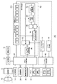
図1は、画像符号化装置、画像復号化装置それぞれの機能を有する画像処理装置として本実施形態で撮像装置を用いた場合に、この撮像装置の概略構成を示す図である。同図により、撮像装置100において本画像の可逆圧縮・記録の際に符号化回路におけるハフマン符号・復号回路を利用して、撮像素子により撮影された画像データを一切の画像処理を施さずに可逆圧縮・記録する場合について説明する。また、RAWデータに関連付けられ、同時記録されるJPEG画像は、撮像素子により撮影された画像データに所定の処理を施した後に符号化回路により非可逆圧縮されるものとする。この同時記録されるJPEG画像を閲覧することにより、RAWデータを現像処理しなくとも、すぐに画像の内容を把握することが可能になる。
FIG. 1 is a diagram illustrating a schematic configuration of an imaging apparatus when the imaging apparatus is used in the present embodiment as an image processing apparatus having functions of an image encoding apparatus and an image decoding apparatus. As shown in the figure, the image data captured by the image sensor is reversibly used without any image processing by using the Huffman code / decoding circuit in the encoding circuit when the image is reversibly compressed and recorded in the
10は撮影像を光学的に結像させる撮像レンズ、12は撮影像をアナログの電気信号に変換する撮像素子(CCD)、14は撮像素子12のアナログ信号出力をデジタル信号に変換するA/D変換器である。ここで、A/D変換器14から出力されたデジタルデータを、以下ではCCD−RAWデータとする。尚、撮像素子は、CMOS等でもよく、CMOSの場合も同様にRAWデータが得られる。
16はD/A変換器、18はTFT LCD等からなる画像表示部である。メモリ40に書き込まれた表示用の画像データはD/A変換器16を介してデジタルデータからアナログデータに変換され、画像表示部18により表示される。
20はメモリカードやハードディスク等の記録媒体であり、撮影された画像データ等は記録媒体20に記録される。
30は画像処理回路であり、撮影、あるいは記録されたCCD−RAWデータに対して所定の画素補間処理や色変換処理等の現像処理やリサイズ処理を行う。
40は撮影した画像データを一時的に格納するためのメモリであり、所定枚数の静止画像や所定時間の動画像を格納するのに十分な記録容量備えている。例えば、A/D変換器14から出力された画像のデジタルデータがメモリ制御回路50、画像処理回路30を介して、あるいは直接メモリ制御回路50を介して、メモリ40に書き込まれる。
50はメモリ制御回路であり、A/D変換器14、D/A変換器16、記録媒体20、画像処理回路30、メモリ40、DPCM変換回路80、符号化回路60へのデータフローを制御する。
A
60は画像データを圧縮・伸長する符号化回路であって、DCT変換回路62、量子化回路64、MUX(データセレクタ)66、ハフマン符号・復号回路68で構成される。データセレクタ66は、JPEG符号化・復号化する場合か、CCD−RAWデータを可逆圧縮・伸長する場合かで切り替えを行う。
An
70はMUX(データセレクタ)で、JPEG符号化・復号化する場合か、CCD−RAWデータを可逆圧縮・伸長する場合かで切り替えを行う。
80は、符号化回路60のハフマン符号・復号回路68を利用してCCD−RAWデータの可逆圧縮伸長処理を行うために、CCD−RAWデータに対してDPCM変換を行う回路である。DPCM変換回路80は、情報源のエントロピーを小さくし、ハフマン符号化における符号化効率を高めるために、CCD−RAWデータのDPCM変換(予測符号化)を行う。DPCM変換回路80は、例えば、10ビットのCCD−RAWデータに対しDPCM変換(予測符号化)、及び11ビットのDPCMデータに対して逆DPCM変換を行う。
DPCM変換は、画像情報が周辺画素との相関関係が強いことを利用して、画像情報を隣接画素(左隣の画素)の画素データと符号化を行う画素の画素データとの差分値に変換する。これにより、情報源のエントロピーを減少させることで、ハフマン符号化における符号化効率を高めることができる。本実施形態では、図2に示すようなCCDカラーフィルタ配列を考慮して、常に2画素左隣の画素データとの差分値を算出する。従って、DPCM変換回路80は入力されたCCD−RAWデータと、2つ前に入力されたCCD−RAWデータとの差分を求めるような構成となっている。
DPCM conversion uses the fact that image information has a strong correlation with surrounding pixels, and converts image information into a difference value between pixel data of an adjacent pixel (the pixel on the left) and pixel data to be encoded. To do. Thereby, the encoding efficiency in Huffman encoding can be improved by reducing the entropy of the information source. In the present embodiment, in consideration of the CCD color filter array as shown in FIG. 2, the difference value with the pixel data adjacent to the left by two pixels is always calculated. Therefore, the
90はモードダイアルスイッチ92による設定に従い、またROM96(読み出し専用メモリ)に格納された内容に従い、撮像装置100全体及び撮像装置100を構成する各回路の動作制御を行うシステム制御回路である。
92はモードダイアルスイッチで、電源オフ、撮影モード、再生モード等の各機能モードを切り替え設定することができる。
96は読み出し専用メモリ(ROM)で、システム制御回路50が使用するプログラム及び、符号化回路60に設定する量子化テーブル、ハフマンテーブルが予め記憶されている。ROM96に格納された量子化テーブルは、メモリ40に一旦転送され、メモリ制御回路50を介して、符号化パラメータ格納メモリ200に保持される。
A read-only memory (ROM) 96 stores a program used by the
200は、符号化パラメータ格納メモリであり、ハフマン符号・復号回路68で使用されるハフマンテーブルを格納している。また、量子化回路64にて、使用される量子化テーブル値を格納している。
An encoding
可逆圧縮時のハフマン符号化におけるDPCMデータの性質とハフマンテーブルの関係について、図3、図4を用いて説明する。図3は、画像データをJPEG符号化した場合に、圧縮率が高い場合について説明した図である。横軸にDPCMデータの予測差分値の絶対値を取り、実線を予測差分値の絶対値の発生頻度、破線をハフマンテーブルの符号長とする。画像の圧縮率は、α=(符号化後の画像データサイズ)/(符号化前の画像データサイズ)によって、定義される。 The relationship between the properties of DPCM data and the Huffman table in Huffman coding during lossless compression will be described with reference to FIGS. FIG. 3 is a diagram illustrating a case where the compression rate is high when image data is JPEG-encoded. The horizontal axis represents the absolute value of the prediction difference value of DPCM data, the solid line represents the occurrence frequency of the absolute value of the prediction difference value, and the broken line represents the code length of the Huffman table. The image compression rate is defined by α = (image data size after encoding) / (image data size before encoding).
一般に、圧縮率が高い画像データの場合、画像データの画素間の相関が高いため、予測差分値の絶対値が小さいところに発生頻度が偏っている。そこで、小さい予測差分値の絶対値に短い符号長、大きい予測差分値の絶対値に長い符号長を割り当てるようなハフマンテーブルを適用すると、ハフマン符号化データが小さくなる。 In general, in the case of image data with a high compression rate, since the correlation between pixels of the image data is high, the occurrence frequency is biased where the absolute value of the prediction difference value is small. Therefore, applying a Huffman table in which a short code length is assigned to the absolute value of the small prediction difference value and a long code length is assigned to the absolute value of the large prediction difference value, the Huffman encoded data becomes small.
図4は、画像データをJPEG符号化した場合に、圧縮率が低い場合について説明した図である。一般に、符号化後の圧縮率が低い画像データの場合、画像データの各画素の相関が低いために、予測差分値の絶対値が小さいものから大きいものまでなだらかな発生頻度で分布している。そのため、小さい予測差分値の絶対値から大きい予測差分値の絶対値まで、それほど大きな差のない符号長を割り当てるハフマンテーブルを適用すると、ハフマン符号化データは小さくなる。 FIG. 4 is a diagram illustrating a case where the compression rate is low when the image data is JPEG encoded. In general, in the case of image data with a low compression rate after encoding, since the correlation between the pixels of the image data is low, the absolute value of the prediction difference value is distributed with a gentle occurrence frequency from a small value to a large value. Therefore, when a Huffman table that assigns code lengths that are not so large from the absolute value of a small prediction difference value to the absolute value of a large prediction difference value is applied, the Huffman encoded data becomes small.
第1の実施形態において、CCD−RAWデータからJPEG画像データ及び圧縮RAWデータを生成する手順を、図5のフローチャート、及び、図6のグラフを用いて説明する。なお、ハフマンテーブルは、予め統計的に算出されており、前述のとおり、ROM96から、システム制御回路90、メモリ40を介して、符号化パラメータ格納メモリ200に保持されているとする。
In the first embodiment, a procedure for generating JPEG image data and compressed RAW data from CCD-RAW data will be described with reference to the flowchart of FIG. 5 and the graph of FIG. The Huffman table is statistically calculated in advance, and is stored in the encoding
まず、撮像されてメモリ40に格納されている画像データ(CCD−RAWデータ)がメモリ制御回路50によって取得され、符号化回路60へ送られる(S101)。
First, image data (CCD-RAW data) captured and stored in the
このとき、システム制御回路90は、データセレクタ70及び、データセレクタ66に対して、CCD−RAWデータからJPEG画像データを生成するための信号を送信する。そのため、符号化回路60は、DCT変換回路62、量子化回路64、ハフマン符号・復号回路68を介してJPEG符号化処理を行う。符号化データ(JPEG画像データ)は、メモリ制御回路50を経由して、メモリ40に格納される(S102)。
At this time, the
次に、システム制御回路90は、S102で生成されたJPEG画像データから、符号化に使用された量子化テーブルの値を取得する。「量子化テーブルの値」とは、量子化ステップの大きさを示す値であり、この値が大きいほどJPEG画像データの圧縮率は高くなる。システム制御回路90は、取得した量子化テーブルの値に基づいて、圧縮率−ハフマン変換係数kを選択する(S103)。詳細は図6を参照して後述するが、量子化テーブルの値が大きいほど、kの値は小さくなる。
Next, the
次に、システム制御回路90は、S102で生成されたJPEG画像データの圧縮率α(JPEG画像データのサイズ/CCD−RAWデータのサイズ)を算出する(S104)。
Next, the
次に、システム制御回路90は、ハフマンテーブル選択値h=k×αに基づき、符号化パラメータ格納メモリからハフマンテーブルを選択する(S105)。図6を参照して、詳細を説明する。
Next, the
図6のグラフは、横軸は圧縮率αであり左から右へ行くほど圧縮率は低くなる(αの値は大きくなる)。また、縦軸は、圧縮率から求められるハフマンテーブル選択値hであり、上から下に行くほど、絶対値が小さい予測差分値に短い符号長、絶対値が大きい予測差分値に長い符号長を割り当てる傾向にある。ここでは、S102で使用され得る量子化テーブルが、Q0、Q1、Q2の三種類あるものとする。Q0は、量子化ステップが小さい量子化テーブル、Q1は、量子化ステップが中程度の量子化テーブル、Q2は、量子化ステップが大きい量子化テーブルとする。 In the graph of FIG. 6, the horizontal axis is the compression rate α, and the compression rate decreases from left to right (the value of α increases). The vertical axis represents the Huffman table selection value h obtained from the compression ratio. As the value goes from top to bottom, a shorter code length is used for a prediction difference value having a smaller absolute value and a longer code length is used for a prediction difference value having a larger absolute value. There is a tendency to assign. Here, it is assumed that there are three types of quantization tables Q0, Q1, and Q2 that can be used in S102. Q0 is a quantization table with a small quantization step, Q1 is a quantization table with a medium quantization step, and Q2 is a quantization table with a large quantization step.
ここで、圧縮率が大きい(αが小さい)ほど、CCD−RAWデータは低周波成分の多い画像データであると推定される。そのため、圧縮RAWデータを生成するために、絶対値が小さい予測差分値に特に短い符号を割り当てるハフマンテーブルが使用されることが好ましい。 Here, it is estimated that CCD-RAW data is image data with many low frequency components, so that a compression rate is large ((alpha) is small). Therefore, in order to generate compressed RAW data, it is preferable to use a Huffman table that assigns a particularly short code to a prediction difference value having a small absolute value.
しかし、JPEG画像データの圧縮率は、CCD−RAWデータは低周波成分の量だけではなく、量子化ステップの大きさによっても変化する。同じCCD−RAWデータであれば、量子化ステップが小さいほど、圧縮率も小さくなる(αが大きくなる)。そこで、量子化テーブルの値に基づいて前述の圧縮率−ハフマン変換係数kを選択することにより、図6のグラフに示すように、ハフマンテーブル選択値hを算出する。 However, the compression rate of JPEG image data varies not only with the amount of low-frequency components in CCD-RAW data but also with the size of the quantization step. For the same CCD-RAW data, the smaller the quantization step, the smaller the compression ratio (α becomes larger). Therefore, by selecting the above-described compression rate-Huffman conversion coefficient k based on the value of the quantization table, the Huffman table selection value h is calculated as shown in the graph of FIG.
図6では、量子化テーブルがQ1であり、αの値がAであるので、ハフマンテーブル選択値は、H2とH3の中間値となるため、選択されるハフマンテーブルは、P2となる。なお、図6のH0〜HNは、ハフマンテーブルPNを選択するための閾値であり、その間隔は任意である。また、閾値の数も任意であり、閾値の数が多いほど、システム制御回路90は、多くのハフマンテーブルからハフマンテーブルを選択できる。
In FIG. 6, since the quantization table is Q1 and the value of α is A, the Huffman table selection value is an intermediate value between H2 and H3, so the selected Huffman table is P2. Note that H0 to HN in FIG. 6 are threshold values for selecting the Huffman table PN, and the intervals are arbitrary. The number of threshold values is also arbitrary, and the greater the number of threshold values, the more the
次に、S101と同様に、メモリ制御回路50は再度CCD−RAWデータをメモリ40から取得し、符号化回路60に送る。そして、符号化回路60は、S105で選択したハフマンテーブルを用いて、CCD−RAWデータを圧縮し、圧縮RAWデータを得る(S106)。このとき、システム制御回路90は、データセレクタ70及び、データセレクタ66に対して、RAW可逆圧縮(符号化)を行う信号を送信する。
Next, as in S101, the
以上説明したように、本実施形態によれば、撮像装置100は、まず、CCD−RAWデータをJPEG符号化する。そして、得られたJPEG画像データの圧縮率に基づいてハフマンテーブルを選択し、CCD−RAWデータを符号化する。撮像装置100は、得られたJPEG画像データの圧縮率が大きいほど、CCD−RAWデータは低周波成分の多い画像データであると推定し、絶対値が小さい予測差分値に特に短い符号を割り当てるハフマンテーブルを選択する。反対に、撮像装置100は、得られたJPEG画像データの圧縮率が小さい場合ほど、予測差分値の絶対値の大小に関わらず、比較的均等な長さの符号を割り当てるハフマンテーブルを選択する。
As described above, according to the present embodiment, the
これにより、撮像装置100は、どのハフマンテーブルを使用するかについて試行錯誤する必要が無くなり、高速にハフマンテーブルを選択しつつも、画像データを比較的効率的に符号化することが可能になる。
This eliminates the need for trial and error as to which Huffman table to use, and the
ここで、S103の処理を省略し、量子化テーブルの値に関わらず同じ圧縮率−ハフマン変換係数kが使用されても、本実施形態の効果はある程度得られる。 Here, even if the process of S103 is omitted and the same compression rate-Huffman transform coefficient k is used regardless of the value of the quantization table, the effect of this embodiment can be obtained to some extent.
[第2の実施形態]
第1の実施形態では、撮像装置100は、CCD−RAWデータから生成されたJPEG画像データの圧縮率に基づいて、RAW可逆圧縮のためのハフマンテーブルを選択した。第2の実施形態では、撮像装置100は、CCD−RAWデータから生成された圧縮RAWデータの圧縮率に基づいて、JPEG符号化のための量子化テーブル及びハフマンテーブルを選択する。
[Second Embodiment]
In the first embodiment, the
第2の実施形態において、CCD−RAWデータから圧縮RAWデータ及びJPEG画像データを生成する手順を、図7のフローチャート、及び、図8のグラフを用いて説明する。なお、量子化テーブル及びハフマンテーブルは、予め統計的に算出されており、ROM96から、システム制御回路90、メモリ40を介して、符号化パラメータ格納メモリ200に保持されているとする。
In the second embodiment, a procedure for generating compressed RAW data and JPEG image data from CCD-RAW data will be described with reference to the flowchart of FIG. 7 and the graph of FIG. It is assumed that the quantization table and the Huffman table are statistically calculated in advance and stored in the encoding
まず、撮像されてメモリ40に格納されている画像データ(CCD−RAWデータ)がメモリ制御回路50によって取得され、符号化回路60へ送られる(S201)。
First, image data (CCD-RAW data) captured and stored in the
このとき、システム制御回路90は、データセレクタ70及び、データセレクタ66に対して、CCD−RAWデータから圧縮RAWデータを生成するための信号を送信する。そのため、符号化回路60は、DPCM変換回路80、ハフマン符号・復号回路68を介してRAW可逆圧縮処理を行う。符号化データ(圧縮RAWデータ)は、メモリ制御回路50を経由して、メモリ40に格納される(S202)。
At this time, the
次に、システム制御回路90は、S202で生成された圧縮RAWデータの圧縮率α(圧縮RAWデータのサイズ/CCD−RAWデータのサイズ)を算出する(S203)。
Next, the
次に、システム制御回路90は、S203で算出された圧縮率αから、JPEG画像を生成するのに好適な量子化テーブルを選択する(S204)。一般に、圧縮率が高い画像データは、画像データの画素間の相関が高いたく、低周波成分を多く含む。このような低周波成分を多く含む画像データの場合、人間の目はノイズを敏感に感じる傾向がある。よって、圧縮率が高い画像データの場合、符号化時に発生するブロックノイズ等を軽減させるために、システム制御回路90は、値の小さな量子化テーブルを選択する。反対に、圧縮率が低い場合は、システム制御回路90は、値の大きな量子化テーブルを選択する。図8では、圧縮率が低い(αが大きい)場合には、量子化ステップの大きな量子化テーブルQ2が選択され、圧縮率が高い(αが小さい)場合は、量子化ステップの小さな量子化テーブルQ0が選択されるグラフが示される。また、圧縮率α=Aにおいては、量子化テーブル選択値は、U1とU2の中間値となるため、選択される量子化テーブルは、Q1となる。
Next, the
圧縮RAWデータの圧縮率が低い(αが大きい)画像は、JPEG画像の圧縮率も低くなる傾向にある。そのため、αが大きい場合にJPEG符号化に使用する量子化テーブルの値を大きくし、αが小さい場合に量子化テーブルの値を小さくすることで、生成されるJPEG画像データのサイズのばらつきを抑制できる。 An image with a low compression rate of compressed RAW data (a large α) tends to have a low JPEG image compression rate. Therefore, by increasing the value of the quantization table used for JPEG encoding when α is large and reducing the value of the quantization table when α is small, the variation in the size of the generated JPEG image data is suppressed. it can.
次に、システム制御回路90は、S203で算出された圧縮率αから、JPEG画像を生成するのに好適なハフマンテーブルを選択する(S205)。ハフマンテーブルの選択方法及び、ハフマンテーブルH1〜HNの性質は、第1の実施形態と同様なため、説明は省略する。図8では、圧縮率がαのとき、ハフマンテーブル選択値は、H2とH3の中間値となるため、選択される量子化テーブルは、P2となる例を示している。
Next, the
次に、S201と同様に、メモリ制御回路50は再度CCD−RAWデータをメモリ40から取得し、符号化回路60に送る。そして、符号化回路60は、S204で選択した量子化テーブル及びS205で選択したハフマンテーブルを用いて、CCD−RAWデータをJPEG符号化し、JPEG画像データを得る(S206)。このとき、システム制御回路90は、データセレクタ70及び、データセレクタ66に対して、JPEG符号化を行う信号を送信する。
Next, as in S201, the
以上説明したように、本実施形態によれば、撮像装置100は、まず、CCD−RAWデータをRAW可逆圧縮する。そして、得られた圧縮RAWデータの圧縮率に基づいて量子化テーブル及びハフマンテーブルを選択し、CCD−RAWデータをJPEG符号化する。
As described above, according to the present embodiment, the
これにより、撮像装置100は、どの量子化テーブルやハフマンテーブルを使用するかについて試行錯誤する必要が無くなり、高速に量子化テーブル及びハフマンテーブルを選択しつつも、画像データを比較的効率的にJPEG符号化することが可能になる。
This eliminates the need for trial and error as to which quantization table and Huffman table to use, and the
[第3の実施形態]
第3の実施形態では、撮像装置100は、画像表示部18に表示する表示用画像データをJPEG符号化し、その圧縮率に基づいて、記録媒体20に記録するための画像データをJPEG符号化するためのハフマンテーブルを選択する。図9を参照して、第3の実施形態を説明する。
[Third Embodiment]
In the third embodiment, the
撮像装置100のシャッター(不図示)がレリーズされるとS306に進み、そうでない場合、S302に進む(S301)。
If the shutter (not shown) of the
S302で、撮像装置100は、表示用画像データをメモリ40から取得して符号化回路60へ送る。表示用画像データは、所定のフレームレート(例えば、毎秒30フレーム)で撮像素子12から取得され、画像処理回路30によって画像表示部18での表示用に画像処理され、メモリ40に格納されているものである。
In S <b> 302, the
次に、符号化回路60は、S302で取得した表示用画像データをJPEG符号化する(S303)。
Next, the
次に、システム制御回路90は、S303で得られたJPEG画像データの圧縮率αを算出し(S304)、圧縮率αに基づいてハフマンテーブルを選択する(S305)。ハフマンテーブルの選択処理は、第1の実施形態及び第2の実施形態と同様のため、説明を省略する。
Next, the
このようにして、シャッター(不図示)がレリーズされるまで、S302〜S305の処理が繰り返し実行され、選択されたハフマンテーブルが更新される。 In this way, the processes of S302 to S305 are repeatedly executed until the shutter (not shown) is released, and the selected Huffman table is updated.
S306では、撮像されてメモリ40に格納されている画像データ(CCD−RAWデータ)がメモリ制御回路50によって取得され、符号化回路60へ送られる。
In
次に、符号化回路60は、S306で取得した画像データを、S305で選択したハフマンテーブルを用いてJPEG符号化し、得られたJPEG画像データをメモリ制御回路50を介して記録媒体20に格納する(S307)。S307では、JPEG符号化ではなく、RAW可逆圧縮が行われても構わない。
Next, the
以上説明したように、本実施形態によれば、撮像装置100は、シャッター(不図示)がレリーズされるまで、所定のフレームレートで取得される表示用画像データをJPEG符号化する。そして、得られたJPEG画像データの圧縮率に基づいてハフマンテーブルを逐次選択し更新する。シャッター(不図示)がレリーズされると、撮像装置100は、選択したハフマンテーブルを用いてCCD−RAWデータをJPEG符号化する。
As described above, according to the present embodiment, the
即ち、撮像装置100は、得られたJPEG画像データの圧縮率を目安にしてハフマンテーブルを選択する。
That is, the
これにより、撮像装置100は、どのハフマンテーブルを使用するかについて試行錯誤する必要が無くなり、高速にハフマンテーブルを選択しつつも、画像データを比較的効率的にJPEG符号化することが可能になる。
This eliminates the need for trial and error as to which Huffman table to use, and the
[その他の実施形態]
上述した各実施の形態の処理は、各機能を具現化したソフトウェアのプログラムコードを記録した記憶媒体をシステム或は装置に提供してもよい。そして、そのシステム或は装置のコンピュータ(又はCPUやMPU)が記憶媒体に格納されたプログラムコードを読み出し実行することによって、前述した実施形態の機能を実現することができる。この場合、記憶媒体から読み出されたプログラムコード自体が前述した実施形態の機能を実現することになり、そのプログラムコードを記憶した記憶媒体は本発明を構成することになる。このようなプログラムコードを供給するための記憶媒体としては、例えば、フロッピィ(登録商標)ディスク、ハードディスク、光ディスク、光磁気ディスクなどを用いることができる。或いは、CD−ROM、CD−R、磁気テープ、不揮発性のメモリカード、ROMなどを用いることもできる。
[Other Embodiments]
The processing of each embodiment described above may provide a system or apparatus with a storage medium storing software program codes embodying each function. The functions of the above-described embodiments can be realized by the computer (or CPU or MPU) of the system or apparatus reading and executing the program code stored in the storage medium. In this case, the program code itself read from the storage medium realizes the functions of the above-described embodiments, and the storage medium storing the program code constitutes the present invention. As a storage medium for supplying such a program code, for example, a floppy (registered trademark) disk, a hard disk, an optical disk, a magneto-optical disk, or the like can be used. Alternatively, a CD-ROM, CD-R, magnetic tape, nonvolatile memory card, ROM, or the like can be used.
また、コンピュータが読み出したプログラムコードを実行することにより、前述した各実施の形態の機能が実現されるだけではない。そのプログラムコードの指示に基づき、コンピュータ上で稼動しているOS(オペレーティングシステム)などが実際の処理の一部又は全部を行い、その処理によって前述した各実施の形態の機能が実現される場合も含まれている。 The functions of the above-described embodiments are not only realized by executing the program code read by the computer. In some cases, an OS (operating system) running on the computer performs part or all of the actual processing based on the instruction of the program code, and the functions of the above-described embodiments are realized by the processing. include.
さらに、記憶媒体から読み出されたプログラムコードが、コンピュータに挿入された機能拡張ボードやコンピュータに接続された機能拡張ユニットに備わるメモリに書きこまれてもよい。その後、そのプログラムコードの指示に基づき、その機能拡張ボードや機能拡張ユニットに備わるCPUなどが実際の処理の一部又は全部を行い、その処理によって前述した各実施の形態の機能が実現される場合も含むものである。 Further, the program code read from the storage medium may be written in a memory provided in a function expansion board inserted into the computer or a function expansion unit connected to the computer. After that, the CPU of the function expansion board or function expansion unit performs part or all of the actual processing based on the instruction of the program code, and the functions of the above-described embodiments are realized by the processing. Is also included.
10:撮影レンズ、12:CCD撮像素子、14:A/D変換器、16:D/A変換器、18:画像表示部、20:記録媒体、30:画像処理回路、40:メモリ、50:メモリ制御回路、60:符号化回路、62:DCT変換回路、64:量子化回路、66:MUX、68:ハフマン符号・復号回路、70:MUX、80:DPCM変換回路、90:システム制御回路、92:モードダイアルスイッチ、96:メモリ(ROM)、100:撮像装置 10: photographing lens, 12: CCD image sensor, 14: A / D converter, 16: D / A converter, 18: image display unit, 20: recording medium, 30: image processing circuit, 40: memory, 50: Memory control circuit, 60: coding circuit, 62: DCT conversion circuit, 64: quantization circuit, 66: MUX, 68: Huffman coding / decoding circuit, 70: MUX, 80: DPCM conversion circuit, 90: system control circuit, 92: Mode dial switch, 96: Memory (ROM), 100: Imaging device
Claims (12)
前記画像データを第1の圧縮方式により圧縮符号化して第1の符号化データを生成する第1の圧縮符号化手段と、
前記第1の圧縮方式とは異なる第2の圧縮方式で使用される複数のハフマンテーブルを保持する記憶手段と、
前記第1の符号化データのデータサイズの、前記画像データのデータサイズに対する比率に基づいて、前記記憶手段に保持された前記複数のハフマンテーブルのうちのいずれかを選択する符号化パラメータ選択手段と、
前記画像データを前記符号化パラメータ選択手段が選択したハフマンテーブルを使用して前記第2の圧縮方式により圧縮符号化して前記第2の符号化データを生成する第2の圧縮符号化手段と、
を備えることを特徴とする画像符号化装置。 An image encoding device that compresses and encodes image data to generate second encoded data,
First compression encoding means for compressing and encoding the image data by a first compression method to generate first encoded data;
Storage means for holding a plurality of Huffman tables used in a second compression scheme different from the first compression scheme;
Encoding parameter selection means for selecting one of the plurality of Huffman tables held in the storage means based on the ratio of the data size of the first encoded data to the data size of the image data; ,
Second compression encoding means for compressing and encoding the image data by the second compression method using a Huffman table selected by the encoding parameter selection means, and generating the second encoded data;
An image encoding device comprising:
前記符号化パラメータ選択手段は、前記比率に基づいて、前記記憶手段に保持された前記複数の量子化テーブルのうちのいずれかを選択することを特徴とする請求項1〜7のいずれか1項に記載の画像符号化装置。 The encoding parameter selection unit selects any one of the plurality of quantization tables held in the storage unit based on the ratio. The image encoding device described in 1.
第1の圧縮符号化手段が、前記画像データを第1の圧縮方式により圧縮符号化して第1の符号化データを生成する第1の圧縮符号化ステップと、
符号化パラメータ選択手段が、前記第1の符号化データのデータサイズの、前記画像データのデータサイズに対する比率に基づいて、記憶手段に保持された、前記第1の圧縮方式とは異なる第2の圧縮方式で使用される複数のハフマンテーブルのうちのいずれかを選択する符号化パラメータ選択ステップと、
第2の圧縮符号化手段が、前記画像データを前記符号化パラメータ選択ステップで選択したハフマンテーブルを使用して前記第2の圧縮方式により圧縮符号化して前記第2の符号化データを生成する第2の圧縮符号化ステップと、
を備えることを特徴とする画像符号化方法。 An image encoding method for compressing and encoding image data to generate second encoded data,
A first compression encoding step, wherein the first compression encoding means compresses and encodes the image data by a first compression method to generate first encoded data;
The encoding parameter selection means has a second different from the first compression method held in the storage means based on the ratio of the data size of the first encoded data to the data size of the image data. An encoding parameter selection step for selecting one of a plurality of Huffman tables used in the compression scheme;
A second compression encoding unit configured to generate the second encoded data by compressing and encoding the image data by the second compression method using the Huffman table selected in the encoding parameter selection step; Two compression encoding steps;
An image encoding method comprising:
Priority Applications (6)
| Application Number | Priority Date | Filing Date | Title |
|---|---|---|---|
| JP2006197372A JP4682102B2 (en) | 2005-09-02 | 2006-07-19 | Image coding apparatus and image coding method |
| US11/912,938 US8045815B2 (en) | 2005-09-02 | 2006-08-25 | Image encoding apparatus and image encoding method |
| ES06797242T ES2400089T3 (en) | 2005-09-02 | 2006-08-25 | Device and method of image coding |
| EP20060797242 EP1925150B1 (en) | 2005-09-02 | 2006-08-25 | Image encoding apparatus and image encoding method |
| CN2006800151452A CN101253761B (en) | 2005-09-02 | 2006-08-25 | Image encoding apparatus and image encoding method |
| PCT/JP2006/317293 WO2007026855A1 (en) | 2005-09-02 | 2006-08-25 | Image encoding apparatus and image encoding method |
Applications Claiming Priority (2)
| Application Number | Priority Date | Filing Date | Title |
|---|---|---|---|
| JP2005255612 | 2005-09-02 | ||
| JP2006197372A JP4682102B2 (en) | 2005-09-02 | 2006-07-19 | Image coding apparatus and image coding method |
Publications (3)
| Publication Number | Publication Date |
|---|---|
| JP2007097145A JP2007097145A (en) | 2007-04-12 |
| JP2007097145A5 JP2007097145A5 (en) | 2009-09-03 |
| JP4682102B2 true JP4682102B2 (en) | 2011-05-11 |
Family
ID=37808938
Family Applications (1)
| Application Number | Title | Priority Date | Filing Date |
|---|---|---|---|
| JP2006197372A Expired - Fee Related JP4682102B2 (en) | 2005-09-02 | 2006-07-19 | Image coding apparatus and image coding method |
Country Status (6)
| Country | Link |
|---|---|
| US (1) | US8045815B2 (en) |
| EP (1) | EP1925150B1 (en) |
| JP (1) | JP4682102B2 (en) |
| CN (1) | CN101253761B (en) |
| ES (1) | ES2400089T3 (en) |
| WO (1) | WO2007026855A1 (en) |
Families Citing this family (15)
| Publication number | Priority date | Publication date | Assignee | Title |
|---|---|---|---|---|
| JP2008124530A (en) * | 2006-11-08 | 2008-05-29 | Tokyo Institute Of Technology | Raw data compressing method |
| CN101689357B (en) | 2007-04-11 | 2015-03-04 | Red.Com公司 | Video camera |
| US8237830B2 (en) | 2007-04-11 | 2012-08-07 | Red.Com, Inc. | Video camera |
| JP4869149B2 (en) * | 2007-05-16 | 2012-02-08 | オリンパスイメージング株式会社 | Image data compression apparatus, image data compression method and program |
| US20080285866A1 (en) * | 2007-05-16 | 2008-11-20 | Takashi Ishikawa | Apparatus and method for image data compression |
| TWI362887B (en) | 2008-03-26 | 2012-04-21 | Etron Technology Inc | An over-drive device and method and method for generating compressed frames |
| US9378560B2 (en) * | 2011-06-17 | 2016-06-28 | Advanced Micro Devices, Inc. | Real time on-chip texture decompression using shader processors |
| CN103051341B (en) * | 2012-12-31 | 2016-01-27 | 华为技术有限公司 | Data coding device and method, data deciphering device and method |
| US9521384B2 (en) | 2013-02-14 | 2016-12-13 | Red.Com, Inc. | Green average subtraction in image data |
| CN106851299B (en) * | 2014-05-21 | 2019-11-08 | 三星半导体(中国)研究开发有限公司 | The decoding method and its device based on jpeg file format in mobile device |
| EP3152907B1 (en) * | 2015-05-29 | 2021-01-06 | SZ DJI Technology Co., Ltd. | System and method for video processing |
| JP6589642B2 (en) * | 2016-01-07 | 2019-10-16 | 富士ゼロックス株式会社 | Data processing apparatus and program |
| JP6929044B2 (en) | 2016-11-14 | 2021-09-01 | キヤノン株式会社 | Imaging device, control method of imaging device, and program |
| KR102620350B1 (en) | 2017-07-05 | 2024-01-02 | 레드.컴, 엘엘씨 | Video image data processing in electronic devices |
| KR20210133800A (en) | 2020-04-29 | 2021-11-08 | 삼성전자주식회사 | Image compressing method, encoder, and camera module including the encoder |
Citations (8)
| Publication number | Priority date | Publication date | Assignee | Title |
|---|---|---|---|---|
| JPH05199422A (en) * | 1992-01-20 | 1993-08-06 | Fujitsu General Ltd | Picture transmission equipment |
| JPH05328137A (en) * | 1992-05-20 | 1993-12-10 | Pfu Ltd | Data compressing device |
| JPH0622152A (en) * | 1992-06-30 | 1994-01-28 | Canon Inc | Picture processing unit |
| JPH09233473A (en) * | 1996-02-27 | 1997-09-05 | Matsushita Electric Ind Co Ltd | Video encoder |
| JPH10336647A (en) * | 1997-06-04 | 1998-12-18 | Nikon Corp | Image compression device and computer readable recording medium recording image compression processing program |
| JPH10336682A (en) * | 1997-04-02 | 1998-12-18 | Canon Inc | Coder, its method and storage medium storing the method |
| JP2001169280A (en) * | 1999-12-09 | 2001-06-22 | Sharp Corp | Image compression device, image compression method and storage medium |
| JP2004040300A (en) * | 2002-07-01 | 2004-02-05 | Fuji Photo Film Co Ltd | Image processing apparatus |
Family Cites Families (11)
| Publication number | Priority date | Publication date | Assignee | Title |
|---|---|---|---|---|
| US671418A (en) * | 1901-01-21 | 1901-04-02 | Charles Gulland | Cylinder-pressure controller for brake systems. |
| JP3093233B2 (en) * | 1990-03-16 | 2000-10-03 | キヤノン株式会社 | Image encoding apparatus and method |
| WO1993019434A1 (en) * | 1992-03-17 | 1993-09-30 | Zoran Corporation | Image compression coder having improved bit rate control and block allocation |
| JPH08186814A (en) | 1994-12-28 | 1996-07-16 | Canon Inc | Image compressor |
| US5677689A (en) * | 1995-08-31 | 1997-10-14 | Yovanof; Gregory S. | Fixed rate JPEG compliant still image compression |
| JP4280319B2 (en) | 1998-03-11 | 2009-06-17 | キヤノン株式会社 | Image processing apparatus, image processing method, and computer-readable storage medium |
| JP3748489B2 (en) | 1998-03-11 | 2006-02-22 | キヤノン株式会社 | Image processing apparatus, image processing method, and computer-readable storage medium |
| JP2001326939A (en) | 2000-05-15 | 2001-11-22 | Canon Inc | Image coding device, image decoding device, its method and storage medium |
| ATE528924T1 (en) | 2001-11-22 | 2011-10-15 | Panasonic Corp | VARIABLE LENGTH ENCODING AND DECODING METHOD |
| JP4193406B2 (en) * | 2002-04-16 | 2008-12-10 | 三菱電機株式会社 | Video data conversion apparatus and video data conversion method |
| JP4262017B2 (en) * | 2002-09-26 | 2009-05-13 | キヤノン株式会社 | Image generating apparatus and method |
-
2006
- 2006-07-19 JP JP2006197372A patent/JP4682102B2/en not_active Expired - Fee Related
- 2006-08-25 CN CN2006800151452A patent/CN101253761B/en not_active Expired - Fee Related
- 2006-08-25 ES ES06797242T patent/ES2400089T3/en active Active
- 2006-08-25 EP EP20060797242 patent/EP1925150B1/en not_active Expired - Fee Related
- 2006-08-25 US US11/912,938 patent/US8045815B2/en not_active Expired - Fee Related
- 2006-08-25 WO PCT/JP2006/317293 patent/WO2007026855A1/en active Application Filing
Patent Citations (8)
| Publication number | Priority date | Publication date | Assignee | Title |
|---|---|---|---|---|
| JPH05199422A (en) * | 1992-01-20 | 1993-08-06 | Fujitsu General Ltd | Picture transmission equipment |
| JPH05328137A (en) * | 1992-05-20 | 1993-12-10 | Pfu Ltd | Data compressing device |
| JPH0622152A (en) * | 1992-06-30 | 1994-01-28 | Canon Inc | Picture processing unit |
| JPH09233473A (en) * | 1996-02-27 | 1997-09-05 | Matsushita Electric Ind Co Ltd | Video encoder |
| JPH10336682A (en) * | 1997-04-02 | 1998-12-18 | Canon Inc | Coder, its method and storage medium storing the method |
| JPH10336647A (en) * | 1997-06-04 | 1998-12-18 | Nikon Corp | Image compression device and computer readable recording medium recording image compression processing program |
| JP2001169280A (en) * | 1999-12-09 | 2001-06-22 | Sharp Corp | Image compression device, image compression method and storage medium |
| JP2004040300A (en) * | 2002-07-01 | 2004-02-05 | Fuji Photo Film Co Ltd | Image processing apparatus |
Also Published As
| Publication number | Publication date |
|---|---|
| ES2400089T3 (en) | 2013-04-05 |
| JP2007097145A (en) | 2007-04-12 |
| CN101253761A (en) | 2008-08-27 |
| US8045815B2 (en) | 2011-10-25 |
| EP1925150A4 (en) | 2011-03-23 |
| CN101253761B (en) | 2011-03-30 |
| WO2007026855A1 (en) | 2007-03-08 |
| EP1925150B1 (en) | 2013-01-16 |
| US20090086817A1 (en) | 2009-04-02 |
| EP1925150A1 (en) | 2008-05-28 |
Similar Documents
| Publication | Publication Date | Title |
|---|---|---|
| JP4682102B2 (en) | Image coding apparatus and image coding method | |
| JP4641892B2 (en) | Moving picture encoding apparatus, method, and program | |
| JP2006253768A (en) | Digital camera | |
| JPWO2006098226A1 (en) | Encoding device and moving image recording system provided with encoding device | |
| US8457428B2 (en) | Image coding apparatus, control method thereof, and storage medium | |
| JP6512916B2 (en) | Image pickup apparatus, control method thereof and program | |
| JP4446288B2 (en) | Movie recording apparatus and movie recording processing program | |
| JP2008182527A (en) | Image coding device and method, and imaging system | |
| CN101677385B (en) | Moving-image reproducing apparatus and moving-image reproducing method | |
| JP2010098352A (en) | Image information encoder | |
| JP2017224939A (en) | Imaging apparatus | |
| JP3990392B2 (en) | Variable length decoding apparatus, variable length decoding method, and imaging system | |
| JP2006352335A (en) | Image coding equipment | |
| JP4514666B2 (en) | Video encoding device | |
| JPH10276402A (en) | Image recorder | |
| JP4706567B2 (en) | Image processing method, image processing method program, recording medium storing image processing method program, and image processing apparatus | |
| JP4430731B2 (en) | Digital camera and photographing method | |
| JP4594163B2 (en) | Image coding method and image coding apparatus | |
| JP2009038740A (en) | Image encoding device | |
| JP2005123738A (en) | Apparatus and method of image processing, and electronic camera | |
| JP4209783B2 (en) | Image compression apparatus, image reproduction apparatus, image compression method, image reproduction method, image compression program, and image reproduction program | |
| JP2006333299A (en) | Encoding apparatus, encoding method and image forming apparatus | |
| KR101332299B1 (en) | Image recording apparatus and method thereof | |
| JP2011023928A (en) | Imaging apparatus, image processing apparatus and image processing method | |
| JP6838951B2 (en) | Coding device and coding method |
Legal Events
| Date | Code | Title | Description |
|---|---|---|---|
| A521 | Written amendment |
Free format text: JAPANESE INTERMEDIATE CODE: A523 Effective date: 20090717 |
|
| A621 | Written request for application examination |
Free format text: JAPANESE INTERMEDIATE CODE: A621 Effective date: 20090717 |
|
| A131 | Notification of reasons for refusal |
Free format text: JAPANESE INTERMEDIATE CODE: A131 Effective date: 20101108 |
|
| A521 | Written amendment |
Free format text: JAPANESE INTERMEDIATE CODE: A523 Effective date: 20101228 |
|
| TRDD | Decision of grant or rejection written | ||
| A01 | Written decision to grant a patent or to grant a registration (utility model) |
Free format text: JAPANESE INTERMEDIATE CODE: A01 Effective date: 20110131 |
|
| A01 | Written decision to grant a patent or to grant a registration (utility model) |
Free format text: JAPANESE INTERMEDIATE CODE: A01 |
|
| A61 | First payment of annual fees (during grant procedure) |
Free format text: JAPANESE INTERMEDIATE CODE: A61 Effective date: 20110207 |
|
| R150 | Certificate of patent or registration of utility model |
Ref document number: 4682102 Country of ref document: JP Free format text: JAPANESE INTERMEDIATE CODE: R150 Free format text: JAPANESE INTERMEDIATE CODE: R150 |
|
| FPAY | Renewal fee payment (event date is renewal date of database) |
Free format text: PAYMENT UNTIL: 20140210 Year of fee payment: 3 |
|
| LAPS | Cancellation because of no payment of annual fees |