EP1925150B1 - Image encoding apparatus and image encoding method - Google Patents
Image encoding apparatus and image encoding method Download PDFInfo
- Publication number
- EP1925150B1 EP1925150B1 EP20060797242 EP06797242A EP1925150B1 EP 1925150 B1 EP1925150 B1 EP 1925150B1 EP 20060797242 EP20060797242 EP 20060797242 EP 06797242 A EP06797242 A EP 06797242A EP 1925150 B1 EP1925150 B1 EP 1925150B1
- Authority
- EP
- European Patent Office
- Prior art keywords
- encoding
- image data
- huffman
- compression
- jpeg
- Prior art date
- Legal status (The legal status is an assumption and is not a legal conclusion. Google has not performed a legal analysis and makes no representation as to the accuracy of the status listed.)
- Expired - Fee Related
Links
Images


Classifications
-
- H—ELECTRICITY
- H04—ELECTRIC COMMUNICATION TECHNIQUE
- H04N—PICTORIAL COMMUNICATION, e.g. TELEVISION
- H04N19/00—Methods or arrangements for coding, decoding, compressing or decompressing digital video signals
- H04N19/50—Methods or arrangements for coding, decoding, compressing or decompressing digital video signals using predictive coding
- H04N19/59—Methods or arrangements for coding, decoding, compressing or decompressing digital video signals using predictive coding involving spatial sub-sampling or interpolation, e.g. alteration of picture size or resolution
-
- H—ELECTRICITY
- H04—ELECTRIC COMMUNICATION TECHNIQUE
- H04N—PICTORIAL COMMUNICATION, e.g. TELEVISION
- H04N19/00—Methods or arrangements for coding, decoding, compressing or decompressing digital video signals
- H04N19/10—Methods or arrangements for coding, decoding, compressing or decompressing digital video signals using adaptive coding
- H04N19/102—Methods or arrangements for coding, decoding, compressing or decompressing digital video signals using adaptive coding characterised by the element, parameter or selection affected or controlled by the adaptive coding
- H04N19/124—Quantisation
- H04N19/126—Details of normalisation or weighting functions, e.g. normalisation matrices or variable uniform quantisers
-
- H—ELECTRICITY
- H04—ELECTRIC COMMUNICATION TECHNIQUE
- H04N—PICTORIAL COMMUNICATION, e.g. TELEVISION
- H04N19/00—Methods or arrangements for coding, decoding, compressing or decompressing digital video signals
- H04N19/10—Methods or arrangements for coding, decoding, compressing or decompressing digital video signals using adaptive coding
- H04N19/102—Methods or arrangements for coding, decoding, compressing or decompressing digital video signals using adaptive coding characterised by the element, parameter or selection affected or controlled by the adaptive coding
- H04N19/13—Adaptive entropy coding, e.g. adaptive variable length coding [AVLC] or context adaptive binary arithmetic coding [CABAC]
-
- H—ELECTRICITY
- H04—ELECTRIC COMMUNICATION TECHNIQUE
- H04N—PICTORIAL COMMUNICATION, e.g. TELEVISION
- H04N19/00—Methods or arrangements for coding, decoding, compressing or decompressing digital video signals
- H04N19/10—Methods or arrangements for coding, decoding, compressing or decompressing digital video signals using adaptive coding
- H04N19/134—Methods or arrangements for coding, decoding, compressing or decompressing digital video signals using adaptive coding characterised by the element, parameter or criterion affecting or controlling the adaptive coding
- H04N19/146—Data rate or code amount at the encoder output
- H04N19/15—Data rate or code amount at the encoder output by monitoring actual compressed data size at the memory before deciding storage at the transmission buffer
-
- H—ELECTRICITY
- H04—ELECTRIC COMMUNICATION TECHNIQUE
- H04N—PICTORIAL COMMUNICATION, e.g. TELEVISION
- H04N19/00—Methods or arrangements for coding, decoding, compressing or decompressing digital video signals
- H04N19/10—Methods or arrangements for coding, decoding, compressing or decompressing digital video signals using adaptive coding
- H04N19/134—Methods or arrangements for coding, decoding, compressing or decompressing digital video signals using adaptive coding characterised by the element, parameter or criterion affecting or controlling the adaptive coding
- H04N19/154—Measured or subjectively estimated visual quality after decoding, e.g. measurement of distortion
-
- H—ELECTRICITY
- H04—ELECTRIC COMMUNICATION TECHNIQUE
- H04N—PICTORIAL COMMUNICATION, e.g. TELEVISION
- H04N19/00—Methods or arrangements for coding, decoding, compressing or decompressing digital video signals
- H04N19/10—Methods or arrangements for coding, decoding, compressing or decompressing digital video signals using adaptive coding
- H04N19/169—Methods or arrangements for coding, decoding, compressing or decompressing digital video signals using adaptive coding characterised by the coding unit, i.e. the structural portion or semantic portion of the video signal being the object or the subject of the adaptive coding
- H04N19/17—Methods or arrangements for coding, decoding, compressing or decompressing digital video signals using adaptive coding characterised by the coding unit, i.e. the structural portion or semantic portion of the video signal being the object or the subject of the adaptive coding the unit being an image region, e.g. an object
- H04N19/172—Methods or arrangements for coding, decoding, compressing or decompressing digital video signals using adaptive coding characterised by the coding unit, i.e. the structural portion or semantic portion of the video signal being the object or the subject of the adaptive coding the unit being an image region, e.g. an object the region being a picture, frame or field
-
- H—ELECTRICITY
- H04—ELECTRIC COMMUNICATION TECHNIQUE
- H04N—PICTORIAL COMMUNICATION, e.g. TELEVISION
- H04N19/00—Methods or arrangements for coding, decoding, compressing or decompressing digital video signals
- H04N19/42—Methods or arrangements for coding, decoding, compressing or decompressing digital video signals characterised by implementation details or hardware specially adapted for video compression or decompression, e.g. dedicated software implementation
- H04N19/423—Methods or arrangements for coding, decoding, compressing or decompressing digital video signals characterised by implementation details or hardware specially adapted for video compression or decompression, e.g. dedicated software implementation characterised by memory arrangements
Definitions
- the present invention relates to an image encoding apparatus and an image encoding method which encodes image data and stores it in a storage medium.
- Image data acquired via an image sensing device in an image processing apparatus such as a digital camera is subjected to A/D conversion.
- the resulting digital data is then subjected to necessary image processing, and lossy compression such as JPEG encoding is executed on the processed data.
- the compressed data is stored in a storage medium as JPEG image data. This enables a large number of image data to be efficiently stored in a storage medium having a limited storage capacity.
- CCD-RAW data image sensing device
- compressed RAW data image processing apparatus
- computer software or the like provided by a digital camera manufacturer or the like. Users can then obtain high-quality images.
- each compressed RAW data is stored simultaneously with the corresponding JPEG image data. The user can thus check stored images on the fly, save them as they are, or print them out.
- a digital camera encodes the CCD-RAW data on the basis of various encode parameters.
- the encode parameters indicate, for example, the type of a Huffman table for Huffman encoding in the digital camera and the type of a quantization table for quantization.
- the compression ratio of compressed RAW data or JPEG image data varies depending on the types of encode parameters used.
- the Huffman table indicates what code is to be assigned to what value.
- Japanese Patent Laid-Open No. 2001-326939 proposes a technique for experimentally executing encoding with each of the plural encode parameters held in a storage unit and adopting an encode parameter resulting in the maximum compression ratio.
- the document WO 93/19434 A1 discloses an image compression coder having improved bit rate control and block allocation, wherein first and second statistical passes through the image data are carried out, and wherein a block allocation factor is determined for each block based on a ratio of block activity to target code volume for the coded image data in the first statistical pass.
- the document EP 1 453 208 A1 discloses a variable length de-/coding method, wherein a second code table is formed by optimizing a first code table to the target data to be processed and one of the first and second code tables is selected as a code table that is employed for the assignment of variable length codes in accordance with a quantization parameter or a variable length coding selection signal.
- the present invention is made in view of these circumstances and is featured by providing a technique for quickly selecting an encode parameter for an image encoding apparatus which achieves high compression efficiency.
- an image encoding apparatus as defined in any one of appended claims 1 to 7.
- an image encoding method as defined in appended claim 8.
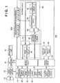
- FIG. 1 is a schematic diagram of an image capturing apparatus according to an embodiment of the present invention
- FIG. 2 is a diagram showing a color filter arrangement in an image sensing device
- FIG. 3 is a diagram showing the relationship between the nature of DPCM data in Huffman encoding with lossless compression and a Huffman table to be applied;
- FIG. 4 is a diagram showing the relationship between the nature of DPCM data in Huffman encoding with lossless compression and a Huffman table to be applied;
- FIG. 5 is a flowchart showing the flow of a process for selecting a Huffman table for RAW lossless compression on the basis of the compression ratio of JPEG image data according to a first embodiment
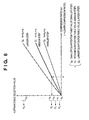
- FIG. 6 is a graph that allows a Huffman table to be selected according to a first embodiment
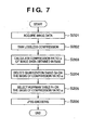
- FIG. 7 is a flowchart showing the flow of a process for selecting a quantization table and a Huffman table for JPEG encoding on the basis of the compression ratio of compressed RAW data according to a second embodiment
- FIG. 8 is a graph that allows a quantization table and a Huffman table to be selected according to a second embodiment.
- FIG. 9 is a flowchart showing the flow of a process for selecting a Huffman table that allows storing JPEG image data to be generated, on the basis of the compression ratio of JPEG image data generated from display image data according to a third embodiment.
- FIG. 1 is a diagram showing the general configuration of an image capturing apparatus used in the present embodiment as an image processing apparatus having the functions of both an image encoding and decoding apparatuses.
- description will be given of lossless compression and storage of an image executed in an image capturing apparatus 100 using a Huffman encoding and decoding circuit in an encoding circuit without carrying out image processing on image data obtained by an image sensing device.
- JPEG images associated with RAW data and stored simultaneously are obtained by executing a predetermined process on image data obtained by the image sensing device and allowing the encoding circuit to subject the processed image data to lossy compression. Navigating the simultaneously stored JPEG images enables the contents of the images to be quickly understood without developing the RAW data.
- Reference numeral 10 denotes an image capturing lens that optically forms a captured image.
- Reference numeral 12 denotes an image sensing device (CCD) that converts the captured image into an analog electric signal.
- Reference numeral 14 denotes an A/D converter that converts an analog signal output from the image sensing device 12 into a digital signal.
- digital data output by the A/D converter 14 is hereinafter referred to as CCD-RAW data.
- the image sensing device may be a CMOS or the like, which similarly provides RAW data.
- Reference numeral 16 denotes a D/A converter and reference numeral 18 denotes an image display unit consisting of a TFT LCD or the like. Display image data written to a memory 40 is converted from digital data into analog data via the D/A converter 16. The resulting analog data is displayed on the image display unit 18.
- Reference numeral 20 denotes a storage medium such as a memory or a hard disk in which captured image data or the like is stored.
- Reference numeral 30 denotes an image processing circuit that executes a predetermined developing process such as pixel interpolating processing or color converting processing, or resize processing on captured or stored CCD-RAW data.
- Reference numeral 40 denotes a memory that temporarily stores captured image data and that has a sufficient storage capacity to store a predetermined number of still images or a predetermined time worth of motion pictures. For example, digital image data output by the A/D converter 14 is written to the memory 40 via a memory control circuit 50 and the image processing circuit 30 or directly via the memory control circuit 50.
- Reference numeral 50 denotes the memory control circuit that controls data flows to the A/D converter 14, D/A converter 16, storage medium 20, image processing circuit 30, and memory 40, as well as a DPCM converting circuit 80 and an encoding circuit 60.
- Reference numeral 60 denotes an encoding circuit that compresses and decompresses image data and that is composed of a DCT converting circuit 62, a quantization circuit 64, a MUX (data selector) 66, and a Huffman encoding and decoding circuit 68.
- the data selector 66 switches between JPEG encoding/decoding and the lossless compression/decompression of CCD-RAW data.
- Reference numeral 70 denotes a MUX (data selector) that switches between JPEG encoding/decoding and the lossless compression/decompression of CCD-RAW data.
- Reference numeral 80 denotes a circuit that executes DPCM conversion on CCD-RAW data so that the Huffman encoding and decoding circuit 68 in the encoding circuit 60 can be used to subject CCD-RAW data to lossless compression and decompression.
- the DPCM converting circuit 80 executes DPCM conversion (predictive encoding) on CCD-RAW data in order to reduce the entropy of an information source to increase the encoding efficiency of the Huffman encoding.
- the DPCM converting circuit 80 executes, for example, DPCM conversion (predictive encoding) on 10-bit CCD-RAW data and inverse DPCM conversion on 11-bit DPCM data.
- the DPCM conversion makes use of the close correlation between neighboring pixels in image information, thus converts the image information into the differential value between pixel data on a pixel to be encoded and pixel data on an adjacent pixel (pixel on the left of the pixel to be encoded). This reduces the entropy of the information source to increase the encoding efficiency of the Huffman encoding.
- the present embodiment uses such a CCD color filter arrangement as shown in FIG. 2 thus always calculates the differential value between data on a target pixel and data on the third pixel from the target pixel on the left.
- the DPCM converting circuit 80 is thus configured to determine the differential between newly input CCD-RAW data and the CCD-RAW data input before the last but one.
- Reference numeral 90 denotes a system control circuit that controls the operations of the entire image capturing apparatus 100 and of the circuits constituting the image capturing apparatus 100 in accordance with settings made via a mode dial switch 92 and settings in a ROM 96 (Read Only Memory).
- Reference numeral 92 denotes the mode dial switch that enables function modes such as power off, image capturing, and playback to be switched and set.
- Reference numeral 96 denotes a read only memory (ROM) that pre-stores programs for the system control circuit 90 and quantization and Huffman tables any of which are to be set in the encoding circuit 60.
- the quantization tables stored in the ROM 96 are transferred to the memory 40 and then held in an encode parameter storing memory 200 via the memory control circuit 50.
- Reference numeral 200 denotes the encode parameter storing memory that stores Huffman tables for the Huffman encoding and decoding circuit 68.
- the encode parameter storing memory also stores quantization tables for the quantization circuit 64.
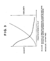
- FIG. 3 is a diagram illustrating that JPEG encoding of image results in a high compression ratio.
- the axis of abscissa indicates the absolute value of a predictive differential value for DPCM data.
- the solid line indicates the incidence of absolute value of the predictive differential value.
- the broken like indicates the code length of the Huffman table.
- Image data with a high compression ratio has a significant correlation between pixels. Higher incidences thus concentrate in an area with smaller absolute values of the predictive differential value.
- the size of Huffman encoding data is thus reduced by using such a Huffman table as assigns a shorter code length to a smaller absolute value of the predictive differential value, while assigning a longer code length to a larger absolute value of the predictive differential value.
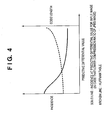
- FIG. 4 is a diagram illustrating that JPEG encoding of image results in a low compression ratio.
- Image data exhibiting a low compression ratio after encoding has an insignificant correlation between pixels. The incidence is distributed so as to insignificantly vary from smaller to larger absolute values of the predictive differential value. The size of Huffman encoding data is thus reduced by using such a Huffman table as assigns an insignificantly varying code length to the smaller to larger absolute values of the predictive differential value.
- Huffman tables are statistically pre-calculated and stored in the ROM 96. The Huffman tables are then transferred to and held in the encode parameter storing memory 200 via the system control circuit 90 and memory 40 as previously described.
- image data (CCD-RAW data) captured and stored in the memory 40 is acquired by the memory control circuit 50, which then sends the data to the encoding circuit 60 (S101).
- the system control circuit 90 transmits a signal for generation of JPEG image data from CCD-RAW data, to the data selectors 70 and 66.
- the encoding circuit 60 thus executes a JPEG encoding process via the DCT converting circuit 62, quantization circuit 64, and Huffman encoding and decoding circuit 68.
- Encoded data JPEG image data
- S102 memory control circuit 50
- the system control circuit 90 then acquires a quantization table value used for encoding from the JPEG image data generated in S102.
- the "quantization table value” indicates the magnitude of a quantization step. A larger quantization table value increases the compression ratio of JPEG image data.
- the system control circuit 90 selects a "compression ratio"- "Huffman” conversion coefficient k (S103). Although described below in detail with reference to FIG. 6 , a smaller quantization table value reduces the value k.
- the system control circuit 90 then calculates the compression ratio ⁇ ((JPEG image data size) / (CCD-RAW data size)) of the JPEG image data generated in S102 (S104).
- the axis of abscissa indicates the compression ratio ⁇ , which becomes lower (value ⁇ increases) from left to right on the axis of abscissa.
- the axis of ordinate indicates the Huffman table selection value h, determined from the compression ratio. The following tendency is more significant from top to bottom of the axis of ordinate: a shorter code length is assigned to a smaller absolute value of the predictive differential value, while a longer code length is assigned to a larger absolute value of the predictive differential value.
- Q0 denotes a quantization table with a small quantization step.
- Q1 denotes a quantization table with a medium quantization step.
- Q2 denotes a quantization table with a large quantization step.
- the compression ratio of JPEG image data varies depending not only on the amount of low frequency components in CCD-RAW data but also on the magnitude of the quantization step. With the same CCD-RAW data, the compression ratio becomes lower (value ⁇ increases) with decreasing magnitude of the quantization step.
- the "compression ratio"-"Huffman" conversion coefficient k is selected on the basis of the quantization table value to calculate the Huffman table selection value h as shown in the graph in FIG. 6 .
- the quantization table is Q1 and the value ⁇ is A. Accordingly, the Huffman table selection value is an intermediate value between H2 and H3. A Huffman table P2 is thus selected.
- H0 to HN in FIG. 6 denote thresholds that allow the Huffman table PN to be selected and that are set at arbitrary intervals. The number of thresholds is also arbitrary. The increased number of thresholds increases the number of Huffman tables one of which can be selected by the system control circuit 90.
- the memory control circuit 50 acquires CCD-RAW data from the RAW memory 40 and sends it to the encoding circuit 60 again, as in the case of S101.
- the encoding circuit 60 uses the Huffman table selected in S105 to compress the CCD-RAW data to obtain compressed RAW data (S106).
- the system control circuit 90 transmits a RAW lossless compression (encoding) signal to the data selectors 70 and 66.
- the image capturing apparatus 100 first executes JPEG encoding on the CCD-RAW data. On the basis of the compression ratio of the JPEG image data obtained, the image capturing apparatus 100 selects a Huffman table to encode the CCD-RAW data. With the higher compression ratio of the JPEG image data obtained, the image capturing apparatus 100 assumes that the CCD-RAW data is image data with a larger number of low frequency components. The image capturing apparatus 100 thus selects a Huffman table that assigns a particularly short code to a predictive differential value with a small absolute value. In contrast, with the lower compression ratio of the JPEG image data obtained, the image capturing apparatus 100 selects a Huffman table that assigns a code of a relatively equal length to the predictive differential value regardless of its absolute value.
- the image capturing apparatus 100 need not repeat trials and errors before determining which Huffman table to use. This in turn makes it possible to relatively efficiently encode image data while quickly selecting a Huffman table.
- the image capturing apparatus 100 selects a Huffman table for RAW lossless compression on the basis of the compression ratio of JPEG image data generated from CCD-RAW data.
- the image capturing apparatus 100 selects a quantization and Huffman tables for JPEG encoding on the basis of the compression ratio of compressed RAW data generated from CCD-RAW data.
- Quantization and Huffman tables are statistically pre-calculated and stored in the ROM 96.
- the Huffman tables are then transferred to and held in the encode parameter storing memory 200 via the system control circuit 90 and memory 40.
- image data (CCD-RAW data) captured and stored in the memory 40 is acquired by the memory control circuit 50, which then sends the data to the encoding circuit 60 (S201).
- the system control circuit 90 transmits a signal for generation of compressed RAW data from CCD-RAW data, to the data selectors 70 and 66.
- the encoding circuit 60 thus executes a RAW lossless compressing process via the DPCM converting circuit 80 and Huffman encoding and decoding circuit 68.
- Encoded data (compressed RAW data) is stored in the memory 40 via the memory control circuit 50 (S202).
- the system control circuit 90 then calculates the compression ratio ⁇ ((compressed RAW data size) /(CCD-RAW data size)) of the compressed RAW data generated in S202 (S203).
- the system control circuit 90 selects a quantization table suitable for generating JPEG images, on the basis of the compression ratio ⁇ calculated in S203 (S204).
- image data with a higher compression ratio exhibits a significant correlation between pixels and contains a large number of low frequency components. Human eyes tend to be more sensitive to noise in image data containing a large number of low frequency components.
- the system control circuit 90 selects a quantization table with a smaller value in order to reduce block noise or the like which may occur during encoding.
- the system control circuit 90 selects a quantization table with a larger value.
- FIG. 8 shows a graph in which a quantization table Q2 with a larger quantization step is selected for a lower compression ratio (larger value ⁇ ) and in which a quantization table Q0 with a smaller quantization step is selected for a higher compression ratio (smaller value ⁇ ).
- the quantization table selection value is an intermediate value between U1 and U2. A quantization table Q1 is thus selected.
- An image having compressed RAW data with a lower compression ratio tends to correspond to JPEG image with a lower compression ratio.
- a variation in the size of JPEG image data generated can be suppressed by increasing the quantization table value for JPEG encoding for a larger value ⁇ , while reducing it for a smaller value ⁇ .
- the system control circuit 90 selects a Huffman table suitable for generating a JPEG image on the basis of the compression ratio ⁇ calculated in S203 (S205).
- a method for selecting a Huffman table and the nature of the Huffman tables P0 to PN according to the second embodiment are similar to those according to the first embodiment and will not be described below.
- the Huffman table selection value is an intermediate value between H2 and H3. The Huffman table P2 is thus selected.
- the memory control circuit 50 then acquires CCD-RAW data from the memory 40 and sends it to the encoding circuit 60 again as is the case with S201.
- the encoding circuit 60 uses the quantization table selected in S204 and the Huffman table selected in S205 to execute JPEG encoding on the CCD-RAW data to obtain JPEG image data (S206).
- the system control circuit 90 transmits a signal for JPEG encoding to the data selectors 70 and 66.
- the image capturing apparatus 100 first subjects CCD-RAW data to RAW lossless compression. On the basis of the compression ratio of the compressed RAW data obtained, the image capturing apparatus 100 selects a quantization and Huffman tables to subject the CCD-RAW data to JPEG encoding.
- the image capturing apparatus 100 need not repeat trials and errors before determining which quantization table and/or Huffman table to use. This makes it possible to relatively efficiently execute JPEG encoding on image data while quickly selecting a quantization table and/or Huffman table.
- the image capturing apparatus 100 executes JPEG encoding on display image data displayed on the image display unit 18. On the basis of the resulting compression ratio, the image capturing apparatus 100 selects a Huffman table that allows JPEG encoding to be executed on image data to be stored in the storage medium 20.
- the third embodiment will be described with reference to FIG. 9 .
- the image capturing apparatus 100 acquires display image data from the memory 40 and sends it to the encoding circuit 60.
- the display image data is acquired through the image sensing device 12 at a predetermined frame rate (for example, 30 frames per second).
- the display image data is then subjected to image processing by the image processing circuit 30 so that the data can be displayed in the image display unit 18.
- the data is then stored in the memory 40.
- the encoding circuit 60 then executes JPEG encoding on the display image data acquired in S302 (S303).
- the system control circuit 90 then calculates the compression ratio ⁇ of the JPEG image data obtained in S303 (S304). On the basis of the compression ratio ⁇ , the system control circuit 90 selects a Huffman table (S305).
- a method for selecting a Huffman table according to the third embodiment is similar to that according to the first and second embodiments and will not be described here.
- image data (CCD-RAW data) captured and stored in the memory 40 is acquired by the memory control circuit 50, which then sends the data to the encoding circuit 60.
- the encoding circuit 60 then uses the Huffman table selected in S305 to execute JPEG encoding on the image data acquired in S306.
- the encoding circuit 60 stores the JPEG image data obtained, in the storage medium 20 via the memory control circuit 50 (S307).
- RAW lossless compression may be executed instead of JPEG encoding.
- the image capturing apparatus 100 continuously executes JPEG encoding on display image data acquired at the predetermined frame rate until the shutter (not shown) is released.
- the image capturing apparatus 100 sequentially selects and updates the Huffman table. Once the shutter (not shown) is released, the image capturing apparatus 100 uses the selected Huffman table to execute JPEG encoding on the CCD-RAW data.
- the image capturing apparatus 100 selects a Huffman table on the basis of the compression ratio of the JPEG image data obtained.
- the image capturing apparatus 100 need not repeat trials and errors before determining which Huffman table to use. This makes it possible to relatively efficiently execute JPEG encoding on image data while quickly selecting a Huffman table.
- the processes of the above embodiments may be executed by providing a system or apparatus with a storage medium in which program codes for software embodying the functions of the embodiments are stored.
- the functions of the above embodiments can then be provided by a computer (or CPU or MPU) in the system or apparatus by reading and executing the program codes stored in the storage medium.
- the program codes themselves read from the storage medium provide the functions of the above embodiments.
- the storage medium in which the program codes are stored constitutes the present invention.
- the storage medium via which the program codes are supplied may be, for example, a floppy (registered trademark) disk, a hard disk, an optical disk, or a magneto optic disk.
- a CD-ROM, a CD-R, a magnetic tape, a nonvolatile memory card, or a ROM may be used.
- the functions of the above embodiments need not necessarily be provided by executing the program codes read by a computer.
- the functions of the above embodiments may also be provided by an OS (Operating System) or the like operating on the computer, by executing a part or all of the actual process on the basis of instructions in the program codes.
- OS Operating System
- the program codes read from the storage medium may be written to a memory provided in an expanded board inserted into the computer or an expanded unit connected to the computer.
- the function of the above embodiments may then be provided by a CPU or the like installed in the expanded board or unit, by executing a part or all of the actual process.
Landscapes
- Engineering & Computer Science (AREA)
- Multimedia (AREA)
- Signal Processing (AREA)
- Compression Or Coding Systems Of Tv Signals (AREA)
- Compression Of Band Width Or Redundancy In Fax (AREA)
- Compression, Expansion, Code Conversion, And Decoders (AREA)
Description
- The present invention relates to an image encoding apparatus and an image encoding method which encodes image data and stores it in a storage medium.
- Image data acquired via an image sensing device in an image processing apparatus such as a digital camera is subjected to A/D conversion. In many cases, the resulting digital data is then subjected to necessary image processing, and lossy compression such as JPEG encoding is executed on the processed data. The compressed data is stored in a storage medium as JPEG image data. This enables a large number of image data to be efficiently stored in a storage medium having a limited storage capacity.
- To focus on image quality, all information obtained via an image sensing device (hereinafter also referred to as "CCD-RAW data") is subjected to lossless compression instead of image processing inside an image processing apparatus such as a digital camera before being stored in a storage medium. The stored image data (hereinafter referred to as "compressed RAW data") is then subjected to image processing using computer software or the like provided by a digital camera manufacturer or the like. Users can then obtain high-quality images. In this case, each compressed RAW data is stored simultaneously with the corresponding JPEG image data. The user can thus check stored images on the fly, save them as they are, or print them out.
- To generate compressed RAW data or JPEG image data from CCD-RAW data, a digital camera encodes the CCD-RAW data on the basis of various encode parameters. The encode parameters indicate, for example, the type of a Huffman table for Huffman encoding in the digital camera and the type of a quantization table for quantization. The compression ratio of compressed RAW data or JPEG image data varies depending on the types of encode parameters used. The Huffman table indicates what code is to be assigned to what value.
- Many conventional digital cameras efficiently store images in a storage medium by selectively applying a preferred one of plural encode parameters so as to maximize the compression ratio. For example, Japanese Patent Laid-Open No.
2001-326939 - However, the conventional technique in Japanese Patent Laid-Open No.
2001-326939
The documentWO 93/19434 A1
Thedocument EP 1 453 208 A1 discloses a variable length de-/coding method, wherein a second code table is formed by optimizing a first code table to the target data to be processed and one of the first and second code tables is selected as a code table that is employed for the assignment of variable length codes in accordance with a quantization parameter or a variable length coding selection signal. - The present invention is made in view of these circumstances and is featured by providing a technique for quickly selecting an encode parameter for an image encoding apparatus which achieves high compression efficiency.
- It is a feature of the present invention to solve the conventional problems.
According to an aspect of the present invention, there is provided an image encoding apparatus as defined in any one of appendedclaims 1 to 7.
According to an aspect of the present invention, there is provided an image encoding method as defined in appended claim 8. - Further features of the present invention will become apparent from the following description of exemplary embodiments with reference to the attached drawings, in which like reference characters designate the same or similar parts throughout the figures thereof.
- The accompanying drawings, which are incorporated in and constitute a part of the specification, illustrate embodiments of the invention and, together with the description, serve to explain the principles of the invention.
-
FIG. 1 is a schematic diagram of an image capturing apparatus according to an embodiment of the present invention; -
FIG. 2 is a diagram showing a color filter arrangement in an image sensing device; -
FIG. 3 is a diagram showing the relationship between the nature of DPCM data in Huffman encoding with lossless compression and a Huffman table to be applied; -
FIG. 4 is a diagram showing the relationship between the nature of DPCM data in Huffman encoding with lossless compression and a Huffman table to be applied; -
FIG. 5 is a flowchart showing the flow of a process for selecting a Huffman table for RAW lossless compression on the basis of the compression ratio of JPEG image data according to a first embodiment; -
FIG. 6 is a graph that allows a Huffman table to be selected according to a first embodiment; -
FIG. 7 is a flowchart showing the flow of a process for selecting a quantization table and a Huffman table for JPEG encoding on the basis of the compression ratio of compressed RAW data according to a second embodiment; -
FIG. 8 is a graph that allows a quantization table and a Huffman table to be selected according to a second embodiment; and -
FIG. 9 is a flowchart showing the flow of a process for selecting a Huffman table that allows storing JPEG image data to be generated, on the basis of the compression ratio of JPEG image data generated from display image data according to a third embodiment. - The present invention will be described below in detail in conjunction with its preferred embodiments, with reference to the accompanying drawings.
- In a first embodiment, description will be given of a technique in which an image capturing apparatus selects an encode parameter for generating compressed RAW data, on the basis of the compression ratio of JPEG image data.
-
FIG. 1 is a diagram showing the general configuration of an image capturing apparatus used in the present embodiment as an image processing apparatus having the functions of both an image encoding and decoding apparatuses. With reference toFIG. 1 , description will be given of lossless compression and storage of an image executed in animage capturing apparatus 100 using a Huffman encoding and decoding circuit in an encoding circuit without carrying out image processing on image data obtained by an image sensing device. JPEG images associated with RAW data and stored simultaneously are obtained by executing a predetermined process on image data obtained by the image sensing device and allowing the encoding circuit to subject the processed image data to lossy compression. Navigating the simultaneously stored JPEG images enables the contents of the images to be quickly understood without developing the RAW data. -
Reference numeral 10 denotes an image capturing lens that optically forms a captured image. Reference numeral 12 denotes an image sensing device (CCD) that converts the captured image into an analog electric signal.Reference numeral 14 denotes an A/D converter that converts an analog signal output from the image sensing device 12 into a digital signal. Here, digital data output by the A/D converter 14 is hereinafter referred to as CCD-RAW data. The image sensing device may be a CMOS or the like, which similarly provides RAW data. -
Reference numeral 16 denotes a D/A converter andreference numeral 18 denotes an image display unit consisting of a TFT LCD or the like. Display image data written to amemory 40 is converted from digital data into analog data via the D/A converter 16. The resulting analog data is displayed on theimage display unit 18. -
Reference numeral 20 denotes a storage medium such as a memory or a hard disk in which captured image data or the like is stored. -
Reference numeral 30 denotes an image processing circuit that executes a predetermined developing process such as pixel interpolating processing or color converting processing, or resize processing on captured or stored CCD-RAW data. -
Reference numeral 40 denotes a memory that temporarily stores captured image data and that has a sufficient storage capacity to store a predetermined number of still images or a predetermined time worth of motion pictures. For example, digital image data output by the A/D converter 14 is written to thememory 40 via amemory control circuit 50 and theimage processing circuit 30 or directly via thememory control circuit 50. -
Reference numeral 50 denotes the memory control circuit that controls data flows to the A/D converter 14, D/A converter 16,storage medium 20,image processing circuit 30, andmemory 40, as well as aDPCM converting circuit 80 and anencoding circuit 60. -
Reference numeral 60 denotes an encoding circuit that compresses and decompresses image data and that is composed of aDCT converting circuit 62, aquantization circuit 64, a MUX (data selector) 66, and a Huffman encoding anddecoding circuit 68. Thedata selector 66 switches between JPEG encoding/decoding and the lossless compression/decompression of CCD-RAW data. -
Reference numeral 70 denotes a MUX (data selector) that switches between JPEG encoding/decoding and the lossless compression/decompression of CCD-RAW data. -
Reference numeral 80 denotes a circuit that executes DPCM conversion on CCD-RAW data so that the Huffman encoding and decodingcircuit 68 in theencoding circuit 60 can be used to subject CCD-RAW data to lossless compression and decompression. TheDPCM converting circuit 80 executes DPCM conversion (predictive encoding) on CCD-RAW data in order to reduce the entropy of an information source to increase the encoding efficiency of the Huffman encoding. TheDPCM converting circuit 80 executes, for example, DPCM conversion (predictive encoding) on 10-bit CCD-RAW data and inverse DPCM conversion on 11-bit DPCM data. - The DPCM conversion makes use of the close correlation between neighboring pixels in image information, thus converts the image information into the differential value between pixel data on a pixel to be encoded and pixel data on an adjacent pixel (pixel on the left of the pixel to be encoded). This reduces the entropy of the information source to increase the encoding efficiency of the Huffman encoding. The present embodiment uses such a CCD color filter arrangement as shown in
FIG. 2 thus always calculates the differential value between data on a target pixel and data on the third pixel from the target pixel on the left. TheDPCM converting circuit 80 is thus configured to determine the differential between newly input CCD-RAW data and the CCD-RAW data input before the last but one. -
Reference numeral 90 denotes a system control circuit that controls the operations of the entireimage capturing apparatus 100 and of the circuits constituting theimage capturing apparatus 100 in accordance with settings made via amode dial switch 92 and settings in a ROM 96 (Read Only Memory).
Reference numeral 92 denotes the mode dial switch that enables function modes such as power off, image capturing, and playback to be switched and set. -
Reference numeral 96 denotes a read only memory (ROM) that pre-stores programs for thesystem control circuit 90 and quantization and Huffman tables any of which are to be set in theencoding circuit 60. The quantization tables stored in theROM 96 are transferred to thememory 40 and then held in an encodeparameter storing memory 200 via thememory control circuit 50. -
Reference numeral 200 denotes the encode parameter storing memory that stores Huffman tables for the Huffman encoding anddecoding circuit 68. The encode parameter storing memory also stores quantization tables for thequantization circuit 64. - With reference to
FIGS. 3 and4 , description will be given of the relationship between the nature of DPCM data in Huffman encoding with lossless compression and the Huffman table.FIG. 3 is a diagram illustrating that JPEG encoding of image results in a high compression ratio. The axis of abscissa indicates the absolute value of a predictive differential value for DPCM data. The solid line indicates the incidence of absolute value of the predictive differential value. The broken like indicates the code length of the Huffman table. The compression ratio of an image is defined by α = (image data size after encoding) /(image data size before encoding). - Image data with a high compression ratio has a significant correlation between pixels. Higher incidences thus concentrate in an area with smaller absolute values of the predictive differential value. The size of Huffman encoding data is thus reduced by using such a Huffman table as assigns a shorter code length to a smaller absolute value of the predictive differential value, while assigning a longer code length to a larger absolute value of the predictive differential value.
-
FIG. 4 is a diagram illustrating that JPEG encoding of image results in a low compression ratio. Image data exhibiting a low compression ratio after encoding has an insignificant correlation between pixels. The incidence is distributed so as to insignificantly vary from smaller to larger absolute values of the predictive differential value. The size of Huffman encoding data is thus reduced by using such a Huffman table as assigns an insignificantly varying code length to the smaller to larger absolute values of the predictive differential value. - With reference to the flowchart in
FIG. 5 and graph inFIG. 6 , description will be given of a procedure for generating JPEG image data and compressed RAW data from CCD-RAW data according to the first embodiment. Huffman tables are statistically pre-calculated and stored in theROM 96. The Huffman tables are then transferred to and held in the encodeparameter storing memory 200 via thesystem control circuit 90 andmemory 40 as previously described. - First, image data (CCD-RAW data) captured and stored in the
memory 40 is acquired by thememory control circuit 50, which then sends the data to the encoding circuit 60 (S101). - At this time, the
system control circuit 90 transmits a signal for generation of JPEG image data from CCD-RAW data, to thedata selectors encoding circuit 60 thus executes a JPEG encoding process via theDCT converting circuit 62,quantization circuit 64, and Huffman encoding anddecoding circuit 68. Encoded data (JPEG image data) is stored in thememory 40 via the memory control circuit 50 (S102). - The
system control circuit 90 then acquires a quantization table value used for encoding from the JPEG image data generated in S102. The "quantization table value" indicates the magnitude of a quantization step. A larger quantization table value increases the compression ratio of JPEG image data. On the basis of the quantization table value acquired, thesystem control circuit 90 selects a "compression ratio"- "Huffman" conversion coefficient k (S103). Although described below in detail with reference toFIG. 6 , a smaller quantization table value reduces the value k. - The
system control circuit 90 then calculates the compression ratio α ((JPEG image data size) / (CCD-RAW data size)) of the JPEG image data generated in S102 (S104).
Thesystem control circuit 90 selects a Huffman table from the encodeparameter storing memory 200 on the basis of a Huffman table selection value h = k x α (S105). This will be described with reference toFIG. 6 . - In the graph in
FIG. 6 , the axis of abscissa indicates the compression ratio α, which becomes lower (value α increases) from left to right on the axis of abscissa. The axis of ordinate indicates the Huffman table selection value h, determined from the compression ratio. The following tendency is more significant from top to bottom of the axis of ordinate: a shorter code length is assigned to a smaller absolute value of the predictive differential value, while a longer code length is assigned to a larger absolute value of the predictive differential value. It is assumed that three quantization tables Q0, Q1, and Q2 are used in S102. Q0 denotes a quantization table with a small quantization step. Q1 denotes a quantization table with a medium quantization step. Q2 denotes a quantization table with a large quantization step. - It is estimated that a higher compression ratio (smaller value α) indicates that the CCD-RAW data is image data with a larger number of low frequency components. Thus, to generate compressed RAW data, it is preferable to use a Huffman table that assigns a particularly short code to a predictive differential value with a small absolute value.
- However, the compression ratio of JPEG image data varies depending not only on the amount of low frequency components in CCD-RAW data but also on the magnitude of the quantization step. With the same CCD-RAW data, the compression ratio becomes lower (value α increases) with decreasing magnitude of the quantization step. The "compression ratio"-"Huffman" conversion coefficient k is selected on the basis of the quantization table value to calculate the Huffman table selection value h as shown in the graph in
FIG. 6 . - In
FIG. 6 , the quantization table is Q1 and the value α is A. Accordingly, the Huffman table selection value is an intermediate value between H2 and H3. A Huffman table P2 is thus selected. H0 to HN inFIG. 6 denote thresholds that allow the Huffman table PN to be selected and that are set at arbitrary intervals. The number of thresholds is also arbitrary. The increased number of thresholds increases the number of Huffman tables one of which can be selected by thesystem control circuit 90. - The
memory control circuit 50 then acquires CCD-RAW data from theRAW memory 40 and sends it to theencoding circuit 60 again, as in the case of S101. Theencoding circuit 60 uses the Huffman table selected in S105 to compress the CCD-RAW data to obtain compressed RAW data (S106). At this time, thesystem control circuit 90 transmits a RAW lossless compression (encoding) signal to thedata selectors - As described above, according to the present embodiment, the
image capturing apparatus 100 first executes JPEG encoding on the CCD-RAW data. On the basis of the compression ratio of the JPEG image data obtained, theimage capturing apparatus 100 selects a Huffman table to encode the CCD-RAW data. With the higher compression ratio of the JPEG image data obtained, theimage capturing apparatus 100 assumes that the CCD-RAW data is image data with a larger number of low frequency components. Theimage capturing apparatus 100 thus selects a Huffman table that assigns a particularly short code to a predictive differential value with a small absolute value. In contrast, with the lower compression ratio of the JPEG image data obtained, theimage capturing apparatus 100 selects a Huffman table that assigns a code of a relatively equal length to the predictive differential value regardless of its absolute value. - Thus, the
image capturing apparatus 100 need not repeat trials and errors before determining which Huffman table to use. This in turn makes it possible to relatively efficiently encode image data while quickly selecting a Huffman table. - Even if the operation in S103 is omitted and the same "compression ratio"-"Huffman" conversion coefficient k is used regardless of the quantization table value, the effects of the present embodiment are exerted to some degree.
- In the first embodiment, the
image capturing apparatus 100 selects a Huffman table for RAW lossless compression on the basis of the compression ratio of JPEG image data generated from CCD-RAW data. In a second embodiment, theimage capturing apparatus 100 selects a quantization and Huffman tables for JPEG encoding on the basis of the compression ratio of compressed RAW data generated from CCD-RAW data. - With reference to the flowchart in
FIG. 7 and graph inFIG. 8 , description will be given of a procedure for generating compressed RAW data and JPEG image data from CCD-RAW data according to the second embodiment. Quantization and Huffman tables are statistically pre-calculated and stored in theROM 96. The Huffman tables are then transferred to and held in the encodeparameter storing memory 200 via thesystem control circuit 90 andmemory 40. - First, image data (CCD-RAW data) captured and stored in the
memory 40 is acquired by thememory control circuit 50, which then sends the data to the encoding circuit 60 (S201). - At this time, the
system control circuit 90 transmits a signal for generation of compressed RAW data from CCD-RAW data, to thedata selectors encoding circuit 60 thus executes a RAW lossless compressing process via theDPCM converting circuit 80 and Huffman encoding anddecoding circuit 68. Encoded data (compressed RAW data) is stored in thememory 40 via the memory control circuit 50 (S202). - The
system control circuit 90 then calculates the compression ratio α ((compressed RAW data size) /(CCD-RAW data size)) of the compressed RAW data generated in S202 (S203). - The
system control circuit 90 then selects a quantization table suitable for generating JPEG images, on the basis of the compression ratio α calculated in S203 (S204). In general, image data with a higher compression ratio exhibits a significant correlation between pixels and contains a large number of low frequency components. Human eyes tend to be more sensitive to noise in image data containing a large number of low frequency components. Thus, for image data with a higher compression ratio, thesystem control circuit 90 selects a quantization table with a smaller value in order to reduce block noise or the like which may occur during encoding. In contrast, for image data with a lower compression ratio, thesystem control circuit 90 selects a quantization table with a larger value.FIG. 8 shows a graph in which a quantization table Q2 with a larger quantization step is selected for a lower compression ratio (larger value α) and in which a quantization table Q0 with a smaller quantization step is selected for a higher compression ratio (smaller value α). At the compression ratio α = A, the quantization table selection value is an intermediate value between U1 and U2. A quantization table Q1 is thus selected. - An image having compressed RAW data with a lower compression ratio (larger value α) tends to correspond to JPEG image with a lower compression ratio. A variation in the size of JPEG image data generated can be suppressed by increasing the quantization table value for JPEG encoding for a larger value α, while reducing it for a smaller value α.
- The
system control circuit 90 then selects a Huffman table suitable for generating a JPEG image on the basis of the compression ratio α calculated in S203 (S205). A method for selecting a Huffman table and the nature of the Huffman tables P0 to PN according to the second embodiment are similar to those according to the first embodiment and will not be described below. In the example shown inFIG. 8 , at the compression ratio A, the Huffman table selection value is an intermediate value between H2 and H3. The Huffman table P2 is thus selected. - The
memory control circuit 50 then acquires CCD-RAW data from thememory 40 and sends it to theencoding circuit 60 again as is the case with S201. Theencoding circuit 60 uses the quantization table selected in S204 and the Huffman table selected in S205 to execute JPEG encoding on the CCD-RAW data to obtain JPEG image data (S206). At this time, thesystem control circuit 90 transmits a signal for JPEG encoding to thedata selectors - As described above, according to the present embodiment, the
image capturing apparatus 100 first subjects CCD-RAW data to RAW lossless compression. On the basis of the compression ratio of the compressed RAW data obtained, theimage capturing apparatus 100 selects a quantization and Huffman tables to subject the CCD-RAW data to JPEG encoding. - Thus, the
image capturing apparatus 100 need not repeat trials and errors before determining which quantization table and/or Huffman table to use. This makes it possible to relatively efficiently execute JPEG encoding on image data while quickly selecting a quantization table and/or Huffman table. - In a third embodiment, the
image capturing apparatus 100 executes JPEG encoding on display image data displayed on theimage display unit 18. On the basis of the resulting compression ratio, theimage capturing apparatus 100 selects a Huffman table that allows JPEG encoding to be executed on image data to be stored in thestorage medium 20. The third embodiment will be described with reference toFIG. 9 . - When a shutter (not shown) of the
image capturing apparatus 100 is released, the process proceeds to S306. Otherwise the process proceeds to S302 (S301). - In S302, the
image capturing apparatus 100 acquires display image data from thememory 40 and sends it to theencoding circuit 60. The display image data is acquired through the image sensing device 12 at a predetermined frame rate (for example, 30 frames per second). The display image data is then subjected to image processing by theimage processing circuit 30 so that the data can be displayed in theimage display unit 18. The data is then stored in thememory 40. - The
encoding circuit 60 then executes JPEG encoding on the display image data acquired in S302 (S303). - The
system control circuit 90 then calculates the compression ratio α of the JPEG image data obtained in S303 (S304). On the basis of the compression ratio α, thesystem control circuit 90 selects a Huffman table (S305). A method for selecting a Huffman table according to the third embodiment is similar to that according to the first and second embodiments and will not be described here. - Thus, the operations in S302 to S305 are repeated to update the selected Huffman table until the shutter (not shown) is released.
- In S306, image data (CCD-RAW data) captured and stored in the
memory 40 is acquired by thememory control circuit 50, which then sends the data to theencoding circuit 60. - The
encoding circuit 60 then uses the Huffman table selected in S305 to execute JPEG encoding on the image data acquired in S306. Theencoding circuit 60 stores the JPEG image data obtained, in thestorage medium 20 via the memory control circuit 50 (S307). In S307, RAW lossless compression may be executed instead of JPEG encoding. - As described above, according to the present embodiment, the
image capturing apparatus 100 continuously executes JPEG encoding on display image data acquired at the predetermined frame rate until the shutter (not shown) is released. On the basis of the compression ratio of the JPEG image data obtained, theimage capturing apparatus 100 sequentially selects and updates the Huffman table. Once the shutter (not shown) is released, theimage capturing apparatus 100 uses the selected Huffman table to execute JPEG encoding on the CCD-RAW data. - In other words, the
image capturing apparatus 100 selects a Huffman table on the basis of the compression ratio of the JPEG image data obtained. - Thus, the
image capturing apparatus 100 need not repeat trials and errors before determining which Huffman table to use. This makes it possible to relatively efficiently execute JPEG encoding on image data while quickly selecting a Huffman table. - The processes of the above embodiments may be executed by providing a system or apparatus with a storage medium in which program codes for software embodying the functions of the embodiments are stored. The functions of the above embodiments can then be provided by a computer (or CPU or MPU) in the system or apparatus by reading and executing the program codes stored in the storage medium. In this case, the program codes themselves read from the storage medium provide the functions of the above embodiments. The storage medium in which the program codes are stored constitutes the present invention. The storage medium via which the program codes are supplied may be, for example, a floppy (registered trademark) disk, a hard disk, an optical disk, or a magneto optic disk. Alternatively, a CD-ROM, a CD-R, a magnetic tape, a nonvolatile memory card, or a ROM may be used.
- The functions of the above embodiments need not necessarily be provided by executing the program codes read by a computer. The functions of the above embodiments may also be provided by an OS (Operating System) or the like operating on the computer, by executing a part or all of the actual process on the basis of instructions in the program codes.
- The program codes read from the storage medium may be written to a memory provided in an expanded board inserted into the computer or an expanded unit connected to the computer. The function of the above embodiments may then be provided by a CPU or the like installed in the expanded board or unit, by executing a part or all of the actual process.
Claims (8)
- An image encoding apparatus comprising:input means arranged to input RAW image data from an image sensing device (12);first compression encoding means (60) arranged to execute first compression encoding on the RAW image data input by said input means to generate JPEG image data, the first compression encoding being executed by a first encoding method including an orthogonal transform process where the image data is transformed into frequency components; andsecond compression encoding means (60) arranged to execute second compression encoding on the RAW image data input by said input means to generate compressed RAW image data, the second compression encoding being executed by a second encoding method including a predictive encoding process where a differential value between a reference pixel data and a target pixel data in the image data is encoded by a variable-length encoding,characterized by:recording means (20) arranged to record both the JPEG image data and the compressed RAW image data which are generated by the first and second compression encoding means from the same RAW image data input from the image sensing device;comparison means (90) arranged to compare a compression ratio of the JPEG image data generated by said first compression encoding means with one or more preset thresholds; andencode parameter determination means (90) arranged to determine an encode parameter for the variable-length encoding of said second compression encoding means in accordance with a comparison result by said comparison means.
- The image encoding apparatus according to claim 1, wherein the variable-length encoding includes Huffman encoding, and the encode parameter includes a Huffman table for the Huffman encoding.
- The image encoding apparatus according to claim 2, wherein
said second compression encoding means is arranged to execute the Huffman encoding using one of a plurality of Huffman tables including a first Huffman table which assigns a code with a shorter code length to the differential value with a smaller absolute value and a second Huffman table which assigns codes with code lengths insignificantly varying from the codes assigned by the first Huffman table to the differential value with the smaller to the higher absolute value, and
said encode parameter determination means is arranged to determine one of the first Huffman table and the second Huffman table in accordance with the comparison result by said comparison means. - The image encoding apparatus according to claim 1, wherein a plurality of the thresholds are set in association with a plurality of encode parameters, and said encode parameter determination means is arranged to determine the encode parameter on the basis of a relationship between a value of the compression ratio and the plurality of thresholds.
- The image encoding apparatus according to claim 4, wherein
the variable-length encoding includes Huffman encoding,
the plurality of encode parameters include Huffman tables which tend to assign a code with shorter code length to the differential value with a smaller absolute value and in which the tendency becomes insignificant stepwise among the tables, and
the plurality of thresholds correspond to the Huffman tables having the stepwise varying tendency. - The image encoding apparatus according to claim 1, wherein
the first encoding method includes a quantization process where the frequency components obtained by the orthogonal transform process are quantized according to one of a plurality of quantization tables and a variable-length encoding process where the frequency components quantized by said quantization process are variable-length encoded, and
the encode parameter determination means is arranged to vary the one or more preset thresholds according to a quantization table used in the quantization process of the first compression encoding means. - The image encoding apparatus according to claim 1, wherein the JPEG image data is used for navigating contents of the compressed RAW image data.
- An image encoding method comprising:an input step (S101) of inputting RAW image data from an image sensing device;a first compression encoding step (S102) of executing first compression encoding on the RAW image data input in said input step to generate JPEG image data, the first compression encoding being executed by a first encoding method including an orthogonal transform process where the image data is transformed into frequency components; anda second compression encoding step (S106) of executing second compression encoding on the RAW image data input in said input step to generate compressed RAW image data, the second compression encoding being executed by a second encoding method including a predictive encoding process where a differential value between a reference pixel data and a target pixel data in the image data is encoded by a variable-length encoding,characterized by:a recording step (S102, S106) of recording both the JPEG image data and the compressed RAW image data which are generated in the first and second compression encoding steps from same RAW image data input from the image sensing device;a comparison step (S103 to S105) of comparing a compression ratio of the JPEG image data generated in said first compression encoding step with one or more preset thresholds; andan encode parameter determination step (S105) of determining an encode parameter for the variable-length encoding of said second compression encoding step in accordance with a comparison result in said comparison step.
Applications Claiming Priority (3)
| Application Number | Priority Date | Filing Date | Title |
|---|---|---|---|
| JP2005255612 | 2005-09-02 | ||
| JP2006197372A JP4682102B2 (en) | 2005-09-02 | 2006-07-19 | Image coding apparatus and image coding method |
| PCT/JP2006/317293 WO2007026855A1 (en) | 2005-09-02 | 2006-08-25 | Image encoding apparatus and image encoding method |
Publications (3)
| Publication Number | Publication Date |
|---|---|
| EP1925150A1 EP1925150A1 (en) | 2008-05-28 |
| EP1925150A4 EP1925150A4 (en) | 2011-03-23 |
| EP1925150B1 true EP1925150B1 (en) | 2013-01-16 |
Family
ID=37808938
Family Applications (1)
| Application Number | Title | Priority Date | Filing Date |
|---|---|---|---|
| EP20060797242 Expired - Fee Related EP1925150B1 (en) | 2005-09-02 | 2006-08-25 | Image encoding apparatus and image encoding method |
Country Status (6)
| Country | Link |
|---|---|
| US (1) | US8045815B2 (en) |
| EP (1) | EP1925150B1 (en) |
| JP (1) | JP4682102B2 (en) |
| CN (1) | CN101253761B (en) |
| ES (1) | ES2400089T3 (en) |
| WO (1) | WO2007026855A1 (en) |
Families Citing this family (15)
| Publication number | Priority date | Publication date | Assignee | Title |
|---|---|---|---|---|
| JP2008124530A (en) * | 2006-11-08 | 2008-05-29 | Tokyo Institute Of Technology | Raw data compressing method |
| AU2008240144A1 (en) | 2007-04-11 | 2008-10-23 | Red.Com, Inc. | Video camera |
| US8237830B2 (en) | 2007-04-11 | 2012-08-07 | Red.Com, Inc. | Video camera |
| JP4869149B2 (en) * | 2007-05-16 | 2012-02-08 | オリンパスイメージング株式会社 | Image data compression apparatus, image data compression method and program |
| US20080285866A1 (en) * | 2007-05-16 | 2008-11-20 | Takashi Ishikawa | Apparatus and method for image data compression |
| TWI362887B (en) | 2008-03-26 | 2012-04-21 | Etron Technology Inc | An over-drive device and method and method for generating compressed frames |
| US9378560B2 (en) * | 2011-06-17 | 2016-06-28 | Advanced Micro Devices, Inc. | Real time on-chip texture decompression using shader processors |
| CN103051341B (en) * | 2012-12-31 | 2016-01-27 | 华为技术有限公司 | Data coding device and method, data deciphering device and method |
| WO2014127153A1 (en) | 2013-02-14 | 2014-08-21 | Red. Com, Inc. | Video camera |
| CN106851299B (en) * | 2014-05-21 | 2019-11-08 | 三星半导体(中国)研究开发有限公司 | The decoding method and its device based on jpeg file format in mobile device |
| WO2016191915A1 (en) | 2015-05-29 | 2016-12-08 | SZ DJI Technology Co., Ltd. | System and method for video processing |
| JP6589642B2 (en) * | 2016-01-07 | 2019-10-16 | 富士ゼロックス株式会社 | Data processing apparatus and program |
| JP6929044B2 (en) | 2016-11-14 | 2021-09-01 | キヤノン株式会社 | Imaging device, control method of imaging device, and program |
| KR102620350B1 (en) | 2017-07-05 | 2024-01-02 | 레드.컴, 엘엘씨 | Video image data processing in electronic devices |
| KR20210133800A (en) | 2020-04-29 | 2021-11-08 | 삼성전자주식회사 | Image compressing method, encoder, and camera module including the encoder |
Family Cites Families (19)
| Publication number | Priority date | Publication date | Assignee | Title |
|---|---|---|---|---|
| US671418A (en) * | 1901-01-21 | 1901-04-02 | Charles Gulland | Cylinder-pressure controller for brake systems. |
| JP3093233B2 (en) * | 1990-03-16 | 2000-10-03 | キヤノン株式会社 | Image encoding apparatus and method |
| JPH05199422A (en) * | 1992-01-20 | 1993-08-06 | Fujitsu General Ltd | Picture transmission equipment |
| EP0630506A4 (en) | 1992-03-17 | 1995-01-04 | Zoran Corporation | Image compression coder having improved bit rate control and block allocation. |
| JPH05328137A (en) * | 1992-05-20 | 1993-12-10 | Pfu Ltd | Data compressing device |
| JP3222554B2 (en) * | 1992-06-30 | 2001-10-29 | キヤノン株式会社 | Image processing apparatus and method |
| JPH08186814A (en) * | 1994-12-28 | 1996-07-16 | Canon Inc | Image compressor |
| US5677689A (en) | 1995-08-31 | 1997-10-14 | Yovanof; Gregory S. | Fixed rate JPEG compliant still image compression |
| JPH09233473A (en) * | 1996-02-27 | 1997-09-05 | Matsushita Electric Ind Co Ltd | Video encoder |
| JPH10336682A (en) * | 1997-04-02 | 1998-12-18 | Canon Inc | Coder, its method and storage medium storing the method |
| JPH10336647A (en) * | 1997-06-04 | 1998-12-18 | Nikon Corp | Image compression device and computer readable recording medium recording image compression processing program |
| JP4280319B2 (en) * | 1998-03-11 | 2009-06-17 | キヤノン株式会社 | Image processing apparatus, image processing method, and computer-readable storage medium |
| JP3748489B2 (en) | 1998-03-11 | 2006-02-22 | キヤノン株式会社 | Image processing apparatus, image processing method, and computer-readable storage medium |
| JP2001169280A (en) * | 1999-12-09 | 2001-06-22 | Sharp Corp | Image compression device, image compression method and storage medium |
| JP2001326939A (en) | 2000-05-15 | 2001-11-22 | Canon Inc | Image coding device, image decoding device, its method and storage medium |
| BR0206629A (en) * | 2001-11-22 | 2004-02-25 | Matsushita Electric Ind Co Ltd | Variable Length Encoding Method and Variable Length Decoding Method |
| JP4193406B2 (en) * | 2002-04-16 | 2008-12-10 | 三菱電機株式会社 | Video data conversion apparatus and video data conversion method |
| JP2004040300A (en) * | 2002-07-01 | 2004-02-05 | Fuji Photo Film Co Ltd | Image processing apparatus |
| JP4262017B2 (en) * | 2002-09-26 | 2009-05-13 | キヤノン株式会社 | Image generating apparatus and method |
-
2006
- 2006-07-19 JP JP2006197372A patent/JP4682102B2/en not_active Expired - Fee Related
- 2006-08-25 EP EP20060797242 patent/EP1925150B1/en not_active Expired - Fee Related
- 2006-08-25 US US11/912,938 patent/US8045815B2/en not_active Expired - Fee Related
- 2006-08-25 WO PCT/JP2006/317293 patent/WO2007026855A1/en active Application Filing
- 2006-08-25 CN CN2006800151452A patent/CN101253761B/en not_active Expired - Fee Related
- 2006-08-25 ES ES06797242T patent/ES2400089T3/en active Active
Also Published As
| Publication number | Publication date |
|---|---|
| EP1925150A4 (en) | 2011-03-23 |
| CN101253761A (en) | 2008-08-27 |
| JP2007097145A (en) | 2007-04-12 |
| US20090086817A1 (en) | 2009-04-02 |
| EP1925150A1 (en) | 2008-05-28 |
| WO2007026855A1 (en) | 2007-03-08 |
| JP4682102B2 (en) | 2011-05-11 |
| US8045815B2 (en) | 2011-10-25 |
| ES2400089T3 (en) | 2013-04-05 |
| CN101253761B (en) | 2011-03-30 |
Similar Documents
| Publication | Publication Date | Title |
|---|---|---|
| EP1925150B1 (en) | Image encoding apparatus and image encoding method | |
| US5216518A (en) | Image processing method and apparatus for encoding variable-length data | |
| JP4979655B2 (en) | Image coding apparatus and control method thereof | |
| US7248191B2 (en) | Variable-length coding method, variable-length coding device and imaging system | |
| CN107431805B (en) | Encoding method and apparatus, and decoding method and apparatus | |
| JPH053550A (en) | Device and method for encoding image data | |
| JP2009165141A (en) | Lossless intraframe encoding using golomb-rice | |
| KR100791295B1 (en) | Flag encoding method, flag decoding method, and apparatus thereof | |
| JP2007049680A (en) | Image compression device and method | |
| JP2005191939A (en) | Image compression apparatus and program for generating predicted difference compressed data of fixed bit length, and, image expansion apparatus, image expansion program, and electronic camera | |
| JP2003531553A (en) | Efficient video data access using fixed compression ratio | |
| JP2006352335A (en) | Image coding equipment | |
| JP2009010612A (en) | Image compressing device and method | |
| JP2007019878A (en) | Image coding apparatus and image coding method | |
| JP2002252759A (en) | Image quantization method and device, and image coder utilizing them | |
| JPH07312751A (en) | Method and device for compressing and coding image data | |
| KR100715512B1 (en) | Apparatus for image processing and method thereof | |
| JP2001231009A (en) | Image data storage device ad method | |
| JP2941913B2 (en) | Image signal recording device | |
| US20070253629A1 (en) | Image Processing Device and Image Forming Device Provided therewith | |
| JP2009038740A (en) | Image encoding device | |
| KR101694293B1 (en) | Method for image compression using metadata of camera | |
| JP2009260747A (en) | Image encoding device, and control method thereof | |
| KR100740646B1 (en) | Method for controling bit rate in encoding type of jpeg image and apparatus tehrefor | |
| JP4262144B2 (en) | Image coding apparatus and method |
Legal Events
| Date | Code | Title | Description |
|---|---|---|---|
| PUAI | Public reference made under article 153(3) epc to a published international application that has entered the european phase |
Free format text: ORIGINAL CODE: 0009012 |
|
| 17P | Request for examination filed |
Effective date: 20080402 |
|
| AK | Designated contracting states |
Kind code of ref document: A1 Designated state(s): DE ES FR GB IT |
|
| DAX | Request for extension of the european patent (deleted) | ||
| RBV | Designated contracting states (corrected) |
Designated state(s): DE ES FR GB IT |
|
| A4 | Supplementary search report drawn up and despatched |
Effective date: 20110218 |
|
| RIC1 | Information provided on ipc code assigned before grant |
Ipc: H04N 1/41 20060101AFI20070518BHEP Ipc: H04N 7/46 20060101ALI20110214BHEP Ipc: H04N 7/32 20060101ALI20110214BHEP Ipc: G06T 9/00 20060101ALI20110214BHEP Ipc: H04N 7/26 20060101ALI20110214BHEP Ipc: H04N 5/232 20060101ALI20110214BHEP |
|
| GRAP | Despatch of communication of intention to grant a patent |
Free format text: ORIGINAL CODE: EPIDOSNIGR1 |
|
| GRAS | Grant fee paid |
Free format text: ORIGINAL CODE: EPIDOSNIGR3 |
|
| GRAA | (expected) grant |
Free format text: ORIGINAL CODE: 0009210 |
|
| AK | Designated contracting states |
Kind code of ref document: B1 Designated state(s): DE ES FR GB IT |
|
| REG | Reference to a national code |
Ref country code: GB Ref legal event code: FG4D |
|
| REG | Reference to a national code |
Ref country code: DE Ref legal event code: R096 Ref document number: 602006034269 Country of ref document: DE Effective date: 20130307 |
|
| REG | Reference to a national code |
Ref country code: ES Ref legal event code: FG2A Ref document number: 2400089 Country of ref document: ES Kind code of ref document: T3 Effective date: 20130405 |
|
| PLBE | No opposition filed within time limit |
Free format text: ORIGINAL CODE: 0009261 |
|
| STAA | Information on the status of an ep patent application or granted ep patent |
Free format text: STATUS: NO OPPOSITION FILED WITHIN TIME LIMIT |
|
| 26N | No opposition filed |
Effective date: 20131017 |
|
| REG | Reference to a national code |
Ref country code: DE Ref legal event code: R097 Ref document number: 602006034269 Country of ref document: DE Effective date: 20131017 |
|
| GBPC | Gb: european patent ceased through non-payment of renewal fee |
Effective date: 20130825 |
|
| PG25 | Lapsed in a contracting state [announced via postgrant information from national office to epo] |
Ref country code: DE Free format text: LAPSE BECAUSE OF NON-PAYMENT OF DUE FEES Effective date: 20140301 |
|
| REG | Reference to a national code |
Ref country code: DE Ref legal event code: R119 Ref document number: 602006034269 Country of ref document: DE Effective date: 20140301 |
|
| PG25 | Lapsed in a contracting state [announced via postgrant information from national office to epo] |
Ref country code: GB Free format text: LAPSE BECAUSE OF NON-PAYMENT OF DUE FEES Effective date: 20130825 |
|
| REG | Reference to a national code |
Ref country code: FR Ref legal event code: PLFP Year of fee payment: 10 |
|
| PGFP | Annual fee paid to national office [announced via postgrant information from national office to epo] |
Ref country code: ES Payment date: 20150817 Year of fee payment: 10 |
|
| PGFP | Annual fee paid to national office [announced via postgrant information from national office to epo] |
Ref country code: FR Payment date: 20150826 Year of fee payment: 10 |
|
| PGFP | Annual fee paid to national office [announced via postgrant information from national office to epo] |
Ref country code: IT Payment date: 20150819 Year of fee payment: 10 |
|
| REG | Reference to a national code |
Ref country code: FR Ref legal event code: ST Effective date: 20170428 |
|
| PG25 | Lapsed in a contracting state [announced via postgrant information from national office to epo] |
Ref country code: FR Free format text: LAPSE BECAUSE OF NON-PAYMENT OF DUE FEES Effective date: 20160831 |
|
| PG25 | Lapsed in a contracting state [announced via postgrant information from national office to epo] |
Ref country code: IT Free format text: LAPSE BECAUSE OF NON-PAYMENT OF DUE FEES Effective date: 20160825 |
|
| PG25 | Lapsed in a contracting state [announced via postgrant information from national office to epo] |
Ref country code: ES Free format text: LAPSE BECAUSE OF NON-PAYMENT OF DUE FEES Effective date: 20160826 |
|
| REG | Reference to a national code |
Ref country code: ES Ref legal event code: FD2A Effective date: 20181203 |