JP4682097B2 - IMAGING DEVICE, ITS CONTROL METHOD, PROGRAM, AND STORAGE MEDIUM - Google Patents
IMAGING DEVICE, ITS CONTROL METHOD, PROGRAM, AND STORAGE MEDIUM Download PDFInfo
- Publication number
- JP4682097B2 JP4682097B2 JP2006180372A JP2006180372A JP4682097B2 JP 4682097 B2 JP4682097 B2 JP 4682097B2 JP 2006180372 A JP2006180372 A JP 2006180372A JP 2006180372 A JP2006180372 A JP 2006180372A JP 4682097 B2 JP4682097 B2 JP 4682097B2
- Authority
- JP
- Japan
- Prior art keywords
- face
- image
- subject
- size
- display
- Prior art date
- Legal status (The legal status is an assumption and is not a legal conclusion. Google has not performed a legal analysis and makes no representation as to the accuracy of the status listed.)
- Expired - Fee Related
Links
Images


Landscapes
- Studio Devices (AREA)
- Focusing (AREA)
- Automatic Focus Adjustment (AREA)
Description
本発明は、静止画像や動画像を撮像する場合に、画面から主たる被写体を選択する技術に関するものである。 The present invention relates to a technique for selecting a main subject from a screen when capturing a still image or a moving image.
従来より、主要被写体に焦点や露出を合わせるために、主要被写体を自動的に判別する撮像装置が知られている。このように自動的に主要被写体を判別する技術として、顔認識を利用したものが提案されている。 2. Description of the Related Art Conventionally, an imaging apparatus that automatically determines a main subject in order to adjust the focus and exposure to the main subject is known. As a technique for automatically discriminating a main subject as described above, a technique using face recognition has been proposed.
例えば、特許文献1では、複数の人物が検出された場合に、主要被写体であると判定される人物に合焦させるカメラが提案されている。主要被写体の判定基準としては、距離が近い、顔の面積が大きい、画面中央に近い、等を採用している。 For example, Patent Document 1 proposes a camera that focuses on a person determined to be a main subject when a plurality of persons are detected. As a criterion for determining the main subject, a short distance, a large face area, close to the center of the screen, and the like are adopted.
また、特許文献2では、ユーザからの指示によって、特徴部位を所定の順番で選択可能なデジタルカメラが提案されている。この技術では、ユーザの操作によって、画面に複数存在する顔を近い順に、或いは大きい順に選択することが可能となっている。
従来では、上記のように、画面中の顔を検出し、距離の近い顔や大きい顔を主要被写体として判別する機能を備えている。これは、距離の近い顔や、大きい顔は主要被写体である可能性が高いと考えられるためである。 Conventionally, as described above, it has a function of detecting a face on the screen and discriminating a face having a short distance or a large face as a main subject. This is because a close face or a large face is highly likely to be a main subject.
しかしながら、常に距離の近い顔や大きい顔が主要被写体であるわけではない。特に、子供を撮影する場合には顔の小さい被写体が主被写体となる。常に顔の大きい被写体を主被写体として選択してしまうと、大人と子供が画面内に含まれる場合、子供を主被写体として選択することができない。子供を撮影するための撮影モード(以下、キッズモードと呼ぶ)の場合は、子供を主被写体として選択できないことは大きな問題である。 However, a close face or a large face is not always the main subject. In particular, when photographing a child, a subject with a small face becomes the main subject. If a subject with a large face is always selected as the main subject, the child cannot be selected as the main subject when an adult and a child are included in the screen. In a shooting mode for shooting a child (hereinafter referred to as a “kids mode”), it is a big problem that the child cannot be selected as a main subject.
従って本発明は上述した課題に鑑みてなされたものであり、その目的は、画面から主たる被写体を自動的に選択する場合の的中率を向上させることである。 Therefore, the present invention has been made in view of the above-described problems, and an object of the present invention is to improve the hit rate when the main subject is automatically selected from the screen.
上述した課題を解決し、目的を達成するために、本発明に係わる撮像装置は、被写体像を光電変換する撮像素子と、前記撮像素子により得られた画像信号から、被写体である人物の顔を検出する顔検出手段と、撮影モードを設定する撮影モード設定手段と、前記顔検出手段により検出された人物の顔から前記撮像素子上に投影された顔の大きさに基づいて主たる被写体を判別すると共に、前記撮影モード設定手段により設定された撮影モードに応じて、前記主たる被写体と判別するための前記顔の大きさの基準を変更する、主被写体判別手段と、を具備することを特徴とする。 In order to solve the above-described problems and achieve the object, an imaging apparatus according to the present invention includes an imaging device that photoelectrically converts a subject image, and an image signal obtained by the imaging device that identifies a human face that is a subject. A main subject is discriminated based on the size of the face projected on the image sensor from the face of the person detected by the face detecting means, the shooting mode setting means for setting the shooting mode, and the face detected by the face detecting means. And main subject discrimination means for changing a reference for the size of the face for discriminating from the main subject in accordance with the shooting mode set by the shooting mode setting means. .
また、本発明に係わる撮像装置の制御方法は、被写体像を光電変換する撮像素子を備える撮像装置を制御する方法であって、前記撮像素子により得られた画像信号から、被写体である人物の顔を検出する顔検出工程と、撮影モードを設定する撮影モード設定工程と、前記顔検出工程において検出された人物の顔から前記撮像素子上に投影された顔の大きさに基づいて主たる被写体を判別すると共に、前記撮影モード設定工程において設定された撮影モードに応じて、前記主たる被写体と判別するための前記顔の大きさの基準を変更する、主被写体判別工程と、を具備することを特徴とする。 The image pickup apparatus control method according to the present invention is a method for controlling an image pickup apparatus including an image pickup device that performs photoelectric conversion on a subject image, and is based on an image signal obtained by the image pickup device. A main object is determined based on the size of the face projected on the image sensor from the face of the person detected in the face detection step. And a main subject determination step of changing a reference for the size of the face for determining the main subject according to the shooting mode set in the shooting mode setting step. To do.
また、本発明に係わるプログラムは、上記の制御方法をコンピュータに実行させることを特徴とする。 A program according to the present invention causes a computer to execute the above control method.
また、本発明に係わる記憶媒体は、上記のプログラムを記憶したことを特徴とする。 A storage medium according to the present invention stores the above program.
本発明によれば、画面から主たる被写体を自動的に選択する場合の的中率を向上させることが可能となる。 According to the present invention, it is possible to improve the hit rate when the main subject is automatically selected from the screen.
以下、本発明の好適な実施形態について、添付図面を参照して詳細に説明する。 DESCRIPTION OF EXEMPLARY EMBODIMENTS Hereinafter, preferred embodiments of the invention will be described in detail with reference to the accompanying drawings.
(第1の実施形態)
図1は、本発明の撮像装置の第1の実施形態であるデジタルカメラのブロック構成を示す図である。
(First embodiment)
FIG. 1 is a diagram showing a block configuration of a digital camera which is a first embodiment of the imaging apparatus of the present invention.
図1において、100はデジタルカメラである。
In FIG. 1,
10は撮影レンズ、12は絞り機能を備えるシャッターである。
14は光学像を電気信号に変換する撮像素子、16は撮像素子14のアナログ出力信号をデジタル信号に変換するA/D変換器である。
An
18は撮像素子14、A/D変換器16、D/A変換器26にクロック信号や制御信号を供給するタイミング発生回路であり、メモリ制御回路22及びシステム制御回路50により制御される。
A
20は画像処理回路であり、A/D変換器16からのデータ或いはメモリ制御回路22からのデータに対して所定の画素補間処理や色変換処理を行う。
An image processing circuit 20 performs predetermined pixel interpolation processing and color conversion processing on the data from the A /
また、画像処理回路20においては、撮像した画像データを用いて所定の演算処理を行い、得られた演算結果に基づいてシステム制御回路50が露光制御部40、測距制御部42に対して制御を行う。これにより、TTL(スルー・ザ・レンズ)方式のAF(オートフォーカス)処理、AE(自動露出)処理、EF(フラッシュプリ発光)処理を行っている。
The image processing circuit 20 performs predetermined calculation processing using the captured image data, and the
さらに、画像処理回路20においては、撮像した画像データを用いて所定の演算処理を行い、得られた演算結果に基づいてTTL方式のAWB(オートホワイトバランス)処理も行っている。 Further, the image processing circuit 20 performs predetermined arithmetic processing using captured image data, and also performs TTL AWB (auto white balance) processing based on the obtained arithmetic result.
22はメモリ制御回路であり、A/D変換器16、タイミング発生回路18、画像処理回路20、画像表示メモリ24、D/A変換器26、メモリ30、圧縮・伸長回路32を制御する。
A
A/D変換器16のデータが画像処理回路20、メモリ制御回路22を介して、或いはA/D変換器16のデータが直接メモリ制御回路22を介して、画像表示メモリ24或いはメモリ30に書き込まれる。
The data of the A /
24は画像表示メモリ、26はD/A変換器、28はTFT,LCD等から成る画像表示部であり、画像表示メモリ24に書き込まれた表示用の画像データはD/A変換器26を介して画像表示部28により表示される。
画像表示部28を用いて撮像した画像データを逐次表示すれば、電子ファインダー機能を実現することが可能である。
If the image data captured using the
また、画像表示部28は、システム制御回路50の指示により任意に表示をON/OFFすることが可能であり、表示をOFFにした場合にはデジタルカメラ100の電力消費を大幅に低減することが出来る。
The
30は撮影した静止画像や動画像を格納するためのメモリであり、所定枚数の静止画像や所定時間の動画像を格納するのに十分な記憶容量を備えている。
これにより、複数枚の静止画像を連続して撮影する連射撮影やパノラマ撮影の場合にも、高速かつ大量の画像書き込みをメモリ30に対して行うことが可能となる。
Thereby, even in the case of continuous shooting or panoramic shooting in which a plurality of still images are continuously shot, it is possible to write a large amount of images to the
また、メモリ30はシステム制御回路50の作業領域としても使用することが可能である。
The
32は適応離散コサイン変換(ADCT)等により画像データを圧縮伸長する圧縮・伸長回路であり、メモリ30に格納された画像を読み込んで圧縮処理或いは伸長処理を行い、処理を終えたデータをメモリ30に書き込む。
40は絞り機能を備えるシャッター12を制御する露光制御部であり、フラッシュ48と連携することによりフラッシュ調光機能も有するものである。
42は撮影レンズ10のフォーカシングを制御する測距制御部、44は撮影レンズ10のズーミングを制御するズーム制御部、46はバリアである保護部102の動作を制御するバリア制御部である。
48はフラッシュであり、AF補助光の投光機能、フラッシュ調光機能も有する。
A
露光制御部40、測距制御部42はTTL方式を用いて制御されており、撮像した画像データを画像処理回路20によって演算した演算結果に基づき、システム制御回路50が露光制御部40、測距制御部42に対して制御を行う。
The
50はデジタルカメラ100全体を制御するシステム制御回路、52はシステム制御回路50の動作用の定数、変数、プログラム等を記憶するメモリである。
A
54はシステム制御回路50でのプログラムの実行に応じて、文字、画像、音声等を用いて動作状態やメッセージ等を表示する液晶表示装置、スピーカー等の表示部である。この表示部は、デジタルカメラ100の操作部近辺の視認し易い位置に単数或いは複数個所設置され、例えばLCDやLED、発音素子等の組み合わせにより構成されている。
また、表示部54は、その一部の機能が光学ファインダー104内に設置されている。
In addition, the
表示部54の表示内容のうち、LCD等に表示するものとしては、例えば、シングルショット/連写撮影表示、セルフタイマー表示、圧縮率表示、記録画素数表示、記録枚数表示、残撮影可能枚数表示がある。また、シャッタースピード表示、絞り値表示、露出補正表示、フラッシュ表示、赤目緩和表示、マクロ撮影表示、ブザー設定表示、時計用電池残量表示、電池残量表示、エラー表示もある。さらに、複数桁の数字による情報表示、記録媒体200及び210の着脱状態表示、通信I/F動作表示、日付け・時刻表示、外部コンピュータとの接続状態を示す表示、等もある。
Among the display contents of the
また、表示部54の表示内容のうち、光学ファインダー104内に表示するものとしては、次のようなものがある。例えば、合焦表示、撮影準備完了表示、手振れ警告表示、フラッシュ充電表示、フラッシュ充電完了表示、シャッタースピード表示、絞り値表示、露出補正表示、記録媒体書き込み動作表示、等である。
Among the display contents of the
さらに、表示部54の表示内容のうち、LED等に表示するものとしては、次のようなものがある。例えば、合焦表示、撮影準備完了表示、手振れ警告表示、フラッシュ充電表示、フラッシュ充電完了表示、記録媒体書き込み動作表示、マクロ撮影設定通知表示、二次電池充電状態表示、等である。
Furthermore, among the display contents of the
そして、表示部54の表示内容のうち、ランプ等に表示するものとしては、例えば、セルフタイマー通知ランプ、等がある。このセルフタイマー通知ランプは、AF補助光と共用して用いても良い。
And what is displayed on a lamp etc. among the display contents of the
56は電気的に消去・記録可能な不揮発性メモリであり、例えばEEPROM等が用いられる。
60、62、64、66及び70は、システム制御回路50の各種の動作指示を入力するための操作部であり、スイッチやダイアル、タッチパネル、視線検知によるポインティング、音声認識装置等の単数或いは複数の組み合わせで構成される。
ここで、これらの操作部の具体的な説明を行う。 Here, a specific description of these operation units will be given.
60はモードダイアルスイッチで、自動撮影モード、プログラム撮影モード、シャッター速度優先撮影モード、絞り優先撮影モード、マニュアル撮影モードを切り替え設定することが出来る。さらに、焦点深度優先(デプス)撮影モード、ポートレート撮影モード、風景撮影モード、接写撮影モード、スポーツ撮影モード、夜景撮影モード、パノラマ撮影モード等の各撮影モードも切り替え設定することが出来る。
62はシャッタースイッチSW1で、不図示のシャッターボタンの操作途中(半押し)でONとなり、AF(オートフォーカス)処理、AE(自動露出)処理、AWB(オートホワイトバランス)処理、EF(フラッシュプリ発光)処理等の動作開始を指示する。
64はシャッタースイッチSW2で、不図示のシャッターボタンの操作完了(全押し)でONとなり、露光処理、現像処理、記録処理という一連の処理の動作開始を指示する。露光処理とは、撮像素子14から読み出した信号をA/D変換器16、メモリ制御回路22を介してメモリ30に書き込む処理である。現像処理とは、画像処理回路20やメモリ制御回路22での演算を用いて画像データを視認可能な状態にする処理である。記録処理とは、メモリ30から画像データを読み出し、圧縮・伸長回路32で圧縮を行い、記録媒体200或いは210に書き込む処理である。
66は再生モードスイッチで、再生モード、マルチ画面再生・消去モード、PC(パーソナルコンピュータ)接続モード等の各機能モードを設定することが出来る。 Reference numeral 66 denotes a playback mode switch which can set various function modes such as a playback mode, a multi-screen playback / erase mode, and a PC (personal computer) connection mode.
68は姿勢モードスイッチで、カメラ姿勢検知部106により、デジタルカメラ100の姿勢を検知し、検知した結果を用いて、撮影時には検知したカメラの姿勢を撮影した画像と共に画像姿勢フラグとして記録媒体に記録する。また、再生時には読み出した画像姿勢フラグに応じて画像の表示方法を切り替える動作を行う姿勢モードのON/OFFを設定する。
70は各種ボタンやタッチパネル等からなる操作部で、メニューボタン、セットボタン、マクロボタン、マルチ画面再生改ページボタン、フラッシュ設定ボタン、単写/連写/セルフタイマー切り替えボタン等が含まれる。また、メニュー移動+(プラス)ボタン、メニュー移動−(マイナス)ボタン、再生画像移動+(プラス)ボタン、再生画像移動−(マイナス)ボタン、撮影画質選択ボタン、露出補正ボタン、日付/時間設定ボタン等も含まれる。また、パノラマモード等の撮影及び再生を実行する際に各種機能の選択及び切り替えを設定する選択/切り替えボタン、パノラマモード等の撮影及び再生を実行する際に各種機能の決定及び実行を設定する決定/実行ボタン等も含まれる。また、画像表示部28のON/OFFを設定する画像表示ON/OFFスイッチ、撮影直後に撮影した画像データを自動再生するクイックレビュー機能を設定するクイックレビューON/OFFスイッチも含まれる。さらに、JPEG圧縮の圧縮率を選択するため或いは撮像素子の信号をそのままデジタル化して記録媒体に記録するCCDRAWモードを選択するためのスイッチである圧縮モードスイッチも含まれる。
An
72は電源スイッチで、電源オン、電源オフの各モードを切り替えることが出来る。
80は電源制御部で、電池検出回路、DC−DCコンバータ、通電するブロックを切り替えるスイッチ回路等により構成されている。そして、電池の装着の有無、電池の種類、電池残量の検出を行い、検出結果及びシステム制御回路50の指示に基づいてDC−DCコンバータを制御し、必要な電圧を必要な期間、記録媒体を含む各部へ供給する。
A
82はコネクタ、84はコネクタ、86はアルカリ電池やリチウム電池等の一次電池や、NiCd電池、NiMH電池、Liイオン電池等の二次電池、ACアダプター等からなる電源部である。
90及び94はメモリカードやハードディスク等の記録媒体とのインタフェース、92及び96はメモリカードやハードディスク等の記録媒体と接続を行うコネクタである。また、98はコネクタ92及び/或いは96に記録媒体200或いは210が装着されているか否かを検知する記録媒体着脱検知部である。
なお、本実施形態では記録媒体を取り付けるインターフェース及びコネクタを2系統持つものとして説明している。もちろん、記録媒体を取り付けるインターフェース及びコネクタは、単数或いは複数、いずれの系統数を備える構成としても構わない。また、異なる規格のインターフェース及びコネクタを組み合わせて備える構成としても構わない。 In the present embodiment, it is assumed that there are two systems of interfaces and connectors for attaching a recording medium. Of course, the interface and the connector for attaching the recording medium may have a single or a plurality of systems and any number of systems. Moreover, it is good also as a structure provided with combining the interface and connector of a different standard.
インターフェース及びコネクタとしては、PCMCIAカードやCF(コンパクトフラッシュ(登録商標))カード等の規格に準拠したものを用いて構成して構わない。 The interface and connector may be configured using a PCMCIA card, a CF (Compact Flash (registered trademark)) card, or the like that conforms to a standard.
さらに、インタフェース90及び94、そしてコネクタ92及び96をPCMCIAカードやCFカード等の規格に準拠したものを用いて構成した場合、以下のようなことが可能である。即ち、LANカードやモデムカード、USBカード、IEEE1394カード、P1284カード、SCSIカード、PHS等の通信カード、等の各種通信カードを接続する。これにより、他のコンピュータやプリンタ等の周辺機器との間で画像データや画像データに付属した管理情報を転送し合うことが出来る。
Furthermore, when the
104は光学ファインダであり、画像表示部28による電子ファインダー機能を使用すること無しに、光学ファインダのみを用いて撮影を行うことが可能である。また、光学ファインダー104内には、表示部54の一部の機能、例えば、合焦表示、手振れ警告表示、フラッシュ充電表示、シャッタースピード表示、絞り値表示、露出補正表示などが設置されている。
106はカメラ姿勢検知部であり、デジタルカメラ100の姿勢を検出することにより、横位置撮影或いは縦位置撮影のいずれの状態かを検知することが出来る。
110は通信部で、RS232CやUSB、IEEE1394、P1284、SCSI、モデム、LAN、無線通信、等の各種通信機能を有する。
A
112は通信部110によりデジタルカメラ100を他の機器と接続するコネクタ或いは無線通信の場合はアンテナである。
200はメモリカードやハードディスク等の記録媒体である。
記録媒体200は、半導体メモリや磁気ディスク等から構成される記録部202、デジタルカメラ100とのインタフェース204、デジタルカメラ100と接続を行うコネクタ206を備えている。
The
210はメモリカードやハードディスク等の記録媒体である。
記録媒体210は、半導体メモリや磁気ディスク等から構成される記録部212、デジタルカメラ100とのインタフェース214、デジタルカメラ100と接続を行うコネクタ216を備えている。
The
次に、図2及び図3は第1の実施形態のデジタルカメラ100の主ルーチンのフローチャートである。
Next, FIGS. 2 and 3 are flowcharts of the main routine of the
図2及び図3を用いて、デジタルカメラ100の動作について説明する。
The operation of the
電池交換等の電源投入により、システム制御回路50はフラグや制御変数等を初期化し(ステップS101)、画像表示部28の画像表示をOFF状態に初期設定する(ステップS102)。
Upon power-on such as battery replacement, the
システム制御回路50は、電源スイッチ72の設定位置を判断し、電源スイッチ72が電源OFFに設定されていたならば(ステップS103)、終了処理を実行した後(ステップS104)、ステップS103に戻る。終了処理では、各表示部の表示を終了状態に変更し、保護部のバリアを閉じて撮像部を保護し、フラグや制御変数等を含む必要なパラメータや設定値、設定モードを不揮発性メモリ56に記録する。また、電源制御部80により画像表示部28を含むデジタルカメラ100各部の不要な電源を遮断する。
The
電源スイッチ72が電源ONに設定されていたならば(ステップS103)、システム制御回路50はモードダイアル60の設定位置を判断し、モードダイアル60が撮影モードに設定されていたならば(ステップS105)、ステップS107に進む。
If the
モードダイアル60がその他のモードに設定されていたならば(ステップS105)、システム制御回路50は選択されたモードに応じた処理を実行し(ステップS106)、処理を終えたならばステップS103に戻る。
If the
システム制御回路50は、電源制御部80により電池等により構成される電源86の残容量や動作情況がデジタルカメラ100の動作に問題があるか否かを判断する(ステップS107)。そして、問題があるならば表示部54を用いて画像や音声により所定の警告表示を行った後に(ステップS109)、ステップS103に戻る。
The
電源86に問題が無いならば(ステップS107)、システム制御回路50は、記録媒体200或いは210が装着されているかどうかの判断、記録媒体200或いは210に記録された画像データの管理情報の取得を行なう。そして、記録媒体200或いは210の動作状態がデジタルカメラ100の動作、特に記録媒体に対する画像データの記録再生動作に問題があるか否かの判断を行う(ステップS108)。記録媒体に問題があるならば表示部54を用いて画像や音声により所定の警告表示を行った後に(ステップS109)、ステップS103に戻る。また、記録媒体に問題が無いならば、ステップS110に進む。
If there is no problem with the power supply 86 (step S107), the
なお、ステップS108においては、システム制御回路50は、記録媒体200或いは210に記録された画像データの最終撮影番号Nmaxの取得も行う。
In step S108, the
最終撮影番号Nmaxは、記録媒体200或いは210より、コネクタ92或いは96、インタフェース90或いは94を介して読み出され、システム制御回路50の内部メモリ或いはメモリ52に記憶される。
The final shooting number Nmax is read from the
ステップS110では、システム制御回路50は表示部54を用いて画像や音声によりデジタルカメラ100の各種設定状態の表示を行う。なお、画像表示部28の画像表示がONであったならば、画像表示部28も用いて画像や音声によりデジタルカメラ100の各種設定状態の表示を行う。
In step S <b> 110, the
次に、図3のステップS121に進み、シャッタースイッチSW1が押されていないならば、ステップS103に戻る。 Next, the process proceeds to step S121 in FIG. 3, and if the shutter switch SW1 is not pressed, the process returns to step S103.
シャッタースイッチSW1が押されたならば(ステップS121)、ステップS122に進む。 If the shutter switch SW1 is pressed (step S121), the process proceeds to step S122.
システム制御回路50は、測距処理を行って撮影レンズ10の焦点を被写体に合わせ、測光処理を行って絞り値及びシャッター時間を決定する(ステップS122)。測光処理において、必要であればフラッシュの設定も行う。
The
この測距・測光処理ステップS122の詳細は図4を用いて後述する。 Details of the distance measurement / photometry processing step S122 will be described later with reference to FIG.
測距・測光処理ステップS122を終え、シャッタースイッチSW2が押されずに(ステップS123)、さらにシャッタースイッチSW1も解除されたならば(ステップS124)、ステップS103に戻る。 If the distance measurement / photometry processing step S122 is completed and the shutter switch SW2 is not pressed (step S123) and the shutter switch SW1 is also released (step S124), the process returns to step S103.
シャッタースイッチSW2が押されたならば(ステップS123)、ステップS125に進む。 If the shutter switch SW2 is pressed (step S123), the process proceeds to step S125.
システム制御回路50は、撮影に備えて保存ファイル名の決定や、新規フォルダの作成など、ファイルやフォルダの管理を行う(ステップS125)。
In preparation for shooting, the
システム制御回路50は、露光処理と現像処理からなる撮影処理を実行する(ステップS126)。露光処理は、撮像素子14、A/D変換器16、画像処理回路20、メモリ制御回路22を介して、或いはA/D変換器から直接メモリ制御回路22を介して、メモリ30に撮影した画像データを書き込む処理である。現像処理は、メモリ制御回路22そして必要に応じて画像処理回路20を用いて、メモリ30に書き込まれた画像データを読み出して画像データを可視画像データに変換する処理である。
The
この撮影処理ステップS126の詳細は図5を用いて後述する。 Details of the photographing processing step S126 will be described later with reference to FIG.
撮影処理ステップS126を終えたならば、クイックレビュー表示を行う(ステップS127)。クイックレビュー表示とは、撮影直後に、撮影した画像を確認のために所定時間画像表示部28に表示する動作である。
When the photographing process step S126 is completed, a quick review display is performed (step S127). The quick review display is an operation for displaying a photographed image on the
クイックレビュー表示ステップS127を終えたならば、システム制御回路50は、メモリ30に書き込まれた撮影画像データを読み出して、メモリ制御回路22そして必要に応じて画像処理回路20を用いて各種画像処理を行う。また、圧縮・伸長回路32を用いて設定したモードに応じた画像圧縮処理を行う。その後、インタフェース90或いは94、コネクタ92或いは96を介して、記録媒体200或いは210へ画像データの書き込みを行う記録処理を実行する(ステップS128)。
When the quick review display step S127 is completed, the
なお、画像表示部28がONの場合は、記録媒体200或いは210へ画像データの書き込みを行っている間、書き込み動作中であることを明示する例えば「BUSY」のような表示を画像表示部28に対して行う。
When the
さらに、表示部54において例えばLEDを点滅させる等の記録媒体書き込み動作表示も併せて行う。
Further, the
記録処理を終えたならば(ステップS128)、ステップS103に戻る。 When the recording process is finished (step S128), the process returns to step S103.
図4は、図3のステップS122における測距・測光処理を示す詳細なフローチャートである。 FIG. 4 is a detailed flowchart showing the distance measurement / photometry processing in step S122 of FIG.
まず、ステップS201において、システム制御回路50は、撮像素子14から電荷信号を読み出し、A/D変換器16を介して画像処理回路20に撮影画像データを読み込む(ステップS201)。この逐次読み込まれた画像データを用いて、画像処理回路20はTTL(スルー・ザ・レンズ)方式のAE(自動露出)処理、EF(フラッシュプリ発光)処理、AF(オートフォーカス)処理に用いる所定の演算を行っている。
First, in step S201, the
なお、ここでの各処理は、撮影した全画素数のうちの必要に応じた特定の部分を必要個所分切り取って抽出し、演算に用いている。これにより、TTL方式のAE、EF、AWB、AFの各処理において、中央重点モード、平均モード、評価モード等の異なるモード毎に最適な演算を行うことが可能となる。 In each processing here, a specific portion of the total number of photographed pixels is extracted by extracting a necessary portion according to necessity and used for calculation. As a result, in each of the TTL method AE, EF, AWB, and AF processes, it is possible to perform an optimal calculation for each different mode such as the center weight mode, the average mode, and the evaluation mode.
この読み込まれた画像データを用いて、画像処理回路20は顔認識処理(画像内の顔を検出する処理)を行う(ステップS202)。 Using this read image data, the image processing circuit 20 performs face recognition processing (processing for detecting a face in the image) (step S202).
なお、画像処理回路20で実施される顔を検出する技術としては、様々な手法が公知となっている。例えば、ニューラルネットワークに代表される学習を用いた方法がある。また、目、鼻、口、および、顔の輪郭といった物理的な形状の特徴のある部位を画像データからテンプレートマッチングを用いて識別する手法がある。他にも、肌の色や目の形といった画像データの特徴量を検出し統計的解析を用いた手法があげられる(例えば、特開平10−232934号公報や特開2000−48184号公報等を参照)。本実施形態では、一対の目(両目)、鼻、口、および、顔の輪郭を検出し、これらの相対位置より人物の顔を決定する手法により顔の識別処理を行っている。 It should be noted that various techniques are known as techniques for detecting a face performed by the image processing circuit 20. For example, there is a method using learning represented by a neural network. In addition, there is a technique for identifying parts having physical shape features such as eyes, nose, mouth, and facial contour from image data using template matching. In addition, there is a technique that detects a feature amount of image data such as skin color or eye shape and uses statistical analysis (for example, Japanese Patent Laid-Open Nos. 10-232934 and 2000-48184). reference). In the present embodiment, face identification processing is performed by detecting a pair of eyes (both eyes), nose, mouth, and face outline, and determining a person's face from their relative positions.
次に、ステップS203では、ステップS202で認識された顔の数を、システム制御回路50の内部メモリ或いはメモリ52中の変数FaceNumに保存する。
Next, in step S203, the number of faces recognized in step S202 is stored in a variable FaceNum in the internal memory of the
システム制御回路50はAFエリアを設定する(ステップS204)。これは、画像データから認識された複数の顔の内のどの顔に焦点を合わせるかを設定する処理である。このAFエリア設定処理の詳細は、図6を用いて後述する。
The
画像処理回路20での演算結果を用いて、システム制御回路50は露出が適正か否かを判断する(ステップS205)。
Using the calculation result in the image processing circuit 20, the
露出が適正でなければ(ステップS205)、システム制御回路50は露光制御部40を用いてAE制御を行い(ステップS206)、ステップS207に進む。
If the exposure is not appropriate (step S205), the
AE制御で得られた測定データを用いて、システム制御回路50はフラッシュが必要か否かを判断し(ステップS207)、フラッシュが必要ならばフラッシュフラグをセットし、フラッシュを充電して(ステップS209)ステップS208に進む。
Using the measurement data obtained by the AE control, the
フラッシュが不要であれば(ステップS207)、ステップS208に進む。 If no flash is required (step S207), the process proceeds to step S208.
ステップS208では、システム制御回路50は、撮像素子14から電荷信号を読み出し、A/D変換器16を介して画像処理回路20に撮影画像データを読み込み、ステップS205に戻る。
In step S208, the
ステップS205で露出が適正と判断したならば、測定データ及び/或いは設定パラメータをシステム制御回路50の内部メモリ或いはメモリ52に記憶する。
If it is determined in step S205 that the exposure is appropriate, the measurement data and / or setting parameters are stored in the internal memory of the
画像処理回路20での演算結果及びAE制御で得られた測定データを用いて、システム制御回路50はホワイトバランス(AWB)が適正と判断されるまで(ステップS210)、画像処理回路20を用いてAWB制御を行う(ステップS211)。
Using the calculation result in the image processing circuit 20 and the measurement data obtained by the AE control, the
ホワイトバランス(AWB)が適正と判断したならば(ステップS210)、測定データ及び/或いは設定パラメータをシステム制御回路50の内部メモリ或いはメモリ52に記憶する。
If it is determined that the white balance (AWB) is appropriate (step S210), the measurement data and / or setting parameters are stored in the internal memory or the
AE制御及びAWB制御で得られた測定データを用いて、システム制御回路50は測距(AF)が合焦と判断されるまで(ステップS212)、測距制御部42を用いてAF制御を行う(ステップS213)。
Using the measurement data obtained by the AE control and the AWB control, the
測距(AF)が合焦と判断したならば(ステップS212)、測定データ及び或いは設定パラメータをシステム制御回路50の内部メモリ或いはメモリ52に記憶し、測距・測光処理ルーチン(図3のステップS122)を終了する。
If it is determined that the distance measurement (AF) is in focus (step S212), the measurement data and / or setting parameters are stored in the internal memory or the
図5は、図3のステップS126における撮影処理を示す詳細なフローチャートである。 FIG. 5 is a detailed flowchart showing the photographing process in step S126 of FIG.
まず、ステップS301,S302では、システム制御回路50は、その内部メモリ或いはメモリ52に記憶されている測光データに従い、露光制御部40によって、絞り機能を有するシャッター12を絞り値に応じて開放して撮像素子14を露光する。
First, in steps S301 and S302, the
フラッシュ・フラグによりフラッシュ48が必要か否かを判断し(ステップS303)、必要な場合はフラッシュを発光させる(ステップS304)。
It is determined whether or not the
システム制御回路50は、測光データに従って撮像素子14の露光終了を待ち(ステップS305)、シャッター12を閉じて(ステップS306)、撮像素子14から電荷信号を読み出す。そして、A/D変換器16、画像処理回路20、メモリ制御回路22を介して、或いはA/D変換器16から直接メモリ制御回路22を介して、メモリ30に撮影画像のデータを書き込む(ステップS307)。
The
一連の処理を終えたならば、撮影処理ルーチンス(図3のテップS126)を終了する。 When the series of processing is finished, the photographing processing routine (step S126 in FIG. 3) is finished.
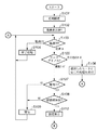
図6は図4のステップS204におけるAFエリア設定処理を示す詳細なフローチャートである。 FIG. 6 is a detailed flowchart showing the AF area setting process in step S204 of FIG.
まず、システム制御回路50は、不揮発性メモリ56等に記憶されているAFエリア選択モードを判断する(ステップS1001)。そして、AFエリアがユーザによる任意選択が可能な設定になっている場合は、ユーザが設定したエリアをAFエリアとして設定し(ステップS1002)、AFエリア設定処理ルーチン(図4のステップS204)を終了する。
First, the
AFエリアが自動設定になっている場合は(ステップS1001)、システム制御回路50の内部メモリ或いはメモリ52中の変数FaceNumが1以上か判定する(ステップS1003)。変数FaceNumは図4のステップS202の顔認識処理の結果検出された顔の数であり、ステップS203においてセットされる。
When the AF area is automatically set (step S1001), it is determined whether the variable FaceNum in the internal memory of the
変数FaceNumが0であった場合は(ステップS1003)、顔認識処理の結果は用いずに、通常のAFエリア設定を行う(ステップS1004)。中央1点AFや、AiAF(複数のAF枠から自動選択)等によりAFエリアが設定される。AFエリア設定後(ステップS1004)、AFエリア設定処理ルーチン(図4のステップS204)を終了する。 When the variable FaceNum is 0 (step S1003), normal AF area setting is performed without using the result of the face recognition process (step S1004). An AF area is set by central one-point AF, AiAF (automatic selection from a plurality of AF frames), or the like. After setting the AF area (step S1004), the AF area setting processing routine (step S204 in FIG. 4) is terminated.
システム制御回路50の内部メモリ或いはメモリ52中の変数FaceNumが1以上である場合は(ステップS1003)、次のような処理を行う。即ち、システム制御回路50はモードダイアル60の設定位置や、システム制御回路50の内部メモリ或いはメモリ52中の変数の値等から現在の撮影モードを判断する(ステップS1005)。
When the variable FaceNum in the internal memory of the
撮影モードがキッズモード(子供をきれいに撮影するモード)以外である場合は(ステップS1005)、ステップS1006に進む。そして、システム制御回路50は顔検出処理ステップS202において検出されたFaceNum個の顔の中で最も大きい顔を決定する(ステップS1006)。そして、ステップS1007に進む。この場合の顔の大きさは撮像素子上の顔の大きさ(撮像素子に投影された顔の大きさ)であり、近距離になるほど顔の大きさは大きくなる。したがって、近距離の顔を決定する処理と類似の効果が期待できる。
If the shooting mode is other than the kids mode (a mode for shooting a child beautifully) (step S1005), the process proceeds to step S1006. Then, the
システム制御回路50は、ステップS1006で決定した撮像素子上のサイズが最も大きな顔に対応するAFエリアを、採用するAFエリアとして設定し(ステップS1007)、AFエリア設定処理ルーチン(図4のステップS204)を終了する。
The
撮影モードがキッズモードである場合は(ステップS1005)、システム制御回路50は図4のステップS202において検出されたFaceNum個の各顔までの距離情報を取得する(ステップS1008)。そして、得られた距離情報と撮像素子上の顔サイズから実顔サイズ(被写体である人物の実際の顔の大きさ)を計算する(ステップS1009)。
When the shooting mode is the kids mode (step S1005), the
ステップS202で検出された全ての顔の実サイズを計算した後(ステップS1009)、システム制御回路50は実サイズ最小の顔を決定する(ステップS1010)。そして、実サイズ最小の顔に対応するAFエリアを、採用するAFエリアに設定する(ステップS1011)。
After calculating the actual sizes of all the faces detected in step S202 (step S1009), the
ステップS1008〜ステップS1011では、一番近い顔を選択するのではなく、子供の顔を選択するのが目的であるため、距離情報を考慮した上で実際の顔のサイズを求め、実サイズの小さい顔を選択する。 In steps S1008 to S1011, the purpose is not to select the closest face but to select the face of a child. Therefore, the actual face size is obtained in consideration of distance information, and the actual size is small. Select a face.
実サイズ最小の顔に対応するAFエリアを、採用するAFエリアに設定した後(ステップS1011)、AFエリア設定処理ルーチン(図4のステップS204)を終了する。 After setting the AF area corresponding to the face having the smallest actual size as the AF area to be adopted (step S1011), the AF area setting processing routine (step S204 in FIG. 4) is ended.
以上説明したように、本実施形態ではキッズモード以外では、顔の大きな被写体及び近距離の被写体を主被写体として選択するとともに、キッズモード時は実際の顔サイズが最小の被写体を主被写体として選択する。したがって、大人と子供が画面に共存している場合でも、キッズモードでは子供を選択することができる。言い換えれば、主たる被写体である子供の顔にピントを合わせたり、露出を合わせたりすることが可能となる。 As described above, in this embodiment, a subject with a large face and a subject at a short distance are selected as main subjects in the mode other than the kids mode, and a subject with the smallest actual face size is selected as the main subject in the kids mode. . Therefore, even when an adult and a child coexist on the screen, the child can be selected in the kids mode. In other words, it is possible to focus on the face of the child, which is the main subject, or to adjust the exposure.
(第2の実施形態)
図2乃至図5、図7を参照して、本発明の第2の実施形態の動作を説明する。
(Second Embodiment)
The operation of the second embodiment of the present invention will be described with reference to FIGS. 2 to 5 and FIG.
第2の実施形態のデジタルカメラの構成は、図1に示した第1の実施形態の構成と同一である。 The configuration of the digital camera of the second embodiment is the same as that of the first embodiment shown in FIG.
第2の実施形態のデジタルカメラ100の主ルーチンのフローチャートは図2及び図3の通りであり、第1の実施形態で説明した通りである。
The flowcharts of the main routine of the
図3のステップS122における測距・測光処理の詳細なフローチャートは図4の通りであり、第1の実施形態で説明した通りである。 A detailed flowchart of the distance measurement / photometry processing in step S122 of FIG. 3 is as shown in FIG. 4 and as described in the first embodiment.
図3のステップS126における撮影処理の詳細なフローチャートは図5の通りであり、第1の実施形態で説明した通りである。 A detailed flowchart of the photographing process in step S126 of FIG. 3 is as shown in FIG. 5, as described in the first embodiment.
図7は、第2の実施形態における、図4のステップS204のAFエリア設定処理の詳細なフローチャートである。 FIG. 7 is a detailed flowchart of the AF area setting process in step S204 of FIG. 4 in the second embodiment.
システム制御回路50は、不揮発性メモリ56等に記憶されているAFエリア選択モードを判断する(ステップS1101)。そして、AFエリアがユーザによる任意選択が可能な設定になっている場合は、ユーザが設定したエリアをAFエリアとして設定し(ステップS1102)、AFエリア設定処理ルーチンを終了する。
The
AFエリアが自動設定になっている場合は(ステップS1101)、システム制御回路50の内部メモリ或いはメモリ52中の変数FaceNumが1以上かを判定する(ステップS1103)。変数FaceNumは、図4のステップS202の顔認識処理の結果検出された顔の数であり、ステップS203においてセットされる。
When the AF area is automatically set (step S1101), it is determined whether the variable FaceNum in the internal memory of the
変数FaceNumが0であった場合は、顔認識処理の結果は用いずに、通常のAFエリア設定を行う(ステップS1104)。中央1点AFや、AiAF(複数のAF枠から自動選択)等によりAFエリアが設定される。AFエリア設定後(ステップS1104)、AFエリア設定処理ルーチンを終了する。 If the variable FaceNum is 0, normal AF area setting is performed without using the result of the face recognition process (step S1104). An AF area is set by central one-point AF, AiAF (automatic selection from a plurality of AF frames), or the like. After setting the AF area (step S1104), the AF area setting processing routine is terminated.
システム制御回路50の内部メモリ或いはメモリ52中の変数FaceNumが1以上である場合は(ステップS1103)、次のような処理を行う。即ち、システム制御回路50はモードダイアル60の設定位置や、システム制御回路50の内部メモリ或いはメモリ52中の変数の値等から現在の撮影モードを判断する(ステップS1105)。
When the variable FaceNum in the internal memory of the
撮影モードがキッズモード以外である場合は(ステップS1105)、システム制御回路50は顔検出処理(図4のステップS202)において検出されたFaceNum個の顔の中で最も大きい顔を決定し(ステップS1106)、ステップS1107に進む。
When the shooting mode is other than the kids mode (step S1105), the
この場合の顔の大きさは撮像素子上の顔の大きさであり、近距離になるほど顔の大きさは大きくなる。したがって、近距離の顔を決定する処理と類似の効果が期待できる。 In this case, the size of the face is the size of the face on the image sensor, and the size of the face increases as the distance decreases. Therefore, an effect similar to the process of determining a face at a short distance can be expected.
システム制御回路50は、ステップS1106で決定した撮像素子上のサイズが最も大きな顔に対応するAFエリアを、採用するAFエリアとして設定し(ステップS1107)、AFエリア設定処理ルーチンを終了する。
The
撮影モードがキッズモードである場合は(ステップS1105)、システム制御回路50はステップS202において検出されたFaceNum個の各顔までの距離情報を取得する(ステップS1108)。そして、得られた距離情報と撮像素子上の顔サイズから実顔サイズ(被写体である人物の実際の顔の大きさ)を計算する(ステップS1109)。
If the shooting mode is the kids mode (step S1105), the
ステップS202で検出された全ての顔の実サイズを計算した後(ステップS1109)、FaceNum個の顔を子供の顔及びそれ以外の顔に分類する(ステップS1110)。分類については、例えば実サイズが所定値以下の顔を子供顔としてグループ化すればよい。 After calculating the actual sizes of all the faces detected in step S202 (step S1109), the FaceNum faces are classified into a child face and other faces (step S1110). For classification, for example, faces whose actual size is a predetermined value or less may be grouped as child faces.
子供顔グループを作成したら(ステップS1110)、子供顔グループの中で最も近距離にある顔を決定し(ステップS1111)、決定した最も近距離にある子供顔に対応するAFエリアを、採用するAFエリアに設定する(ステップS1112)。なお、ステップS1111では、ステップS1108で取得した距離情報を利用すればよい。或いは、距離ではなく最も大きい子供顔を選んでもよい。 When the child face group is created (step S1110), the face closest to the child face group is determined (step S1111), and the AF area corresponding to the determined child face closest to the AF is adopted. The area is set (step S1112). In step S1111, the distance information acquired in step S1108 may be used. Alternatively, the largest child face may be selected instead of the distance.
ステップS1112を終えたら、AFエリア設定処理ルーチンを終了する。 When step S1112 is completed, the AF area setting processing routine is ended.
以上説明したように、本実施形態ではキッズモード以外では、顔の大きな被写体及び近距離の被写体を主被写体として選択するとともに、キッズモード時は実際の顔サイズが所定値以下の子供顔の中で最も近い距離にある顔を主被写体として選択する。したがって、大人と子供が画面に共存している場合でもキッズモードでは子供を選択することができるうえ、子供が複数いる場合でも、主要被写体である可能性の高い近距離或いは顔の大きな(撮像素子上のサイズ)子供を選択することができる。 As described above, in the present embodiment, a subject with a large face and a subject at a short distance are selected as main subjects except in the kids mode. The closest face is selected as the main subject. Therefore, even when an adult and a child coexist on the screen, it is possible to select a child in the kids mode, and even when there are multiple children, a short distance or a large face (image sensor) Top size) Children can be selected.
なお、上記の実施形態では、記録媒体200および210としては、次のようなものを用いることができる。即ち、PCMCIAカードやコンパクトフラッシュ(登録商標)等のメモリカード、ハードディスク等だけでなく、マイクロDAT、光磁気ディスク、CD−RやCD−RW等の光ディスク、DVD等の相変化型光ディスク等でもよい。
In the above embodiment, the following can be used as the
また、記録媒体200及び210は、メモリカードとハードディスク等が一体となった複合媒体であってもよいし、さらに、その複合媒体から一部が着脱可能な構成であってもよい。
Further, the
上記の実施形態においては、記録媒体200及び210は、デジタルカメラ100と分離していて任意に接続可能なものとして説明したが、いずれか或いは全ての記録媒体がデジタルカメラ100に固定されていてもよい。
In the above embodiment, the
また、デジタルカメラ100に記録媒体200或いは210が、単数或いは複数の任意の個数接続可能な構成であってもよい。
Further, the
また、上記の実施形態においては、デジタルカメラ100に記録媒体200及び210を装着する構成として説明したが、記録媒体は単数或いは複数の何れの組み合わせの構成であってもよい。
In the above embodiment, the
なお、本発明は、複数の機器から構成されるシステムに適用しても、一つの機器からなる装置に適用してもよい。 Note that the present invention may be applied to a system composed of a plurality of devices or an apparatus composed of a single device.
また、本発明では、以上の各実施形態、または、それら技術要素を必要に応じて組み合わせるようにしてもよい。 In the present invention, the above-described embodiments or the technical elements may be combined as necessary.
また、本発明は、特許請求の範囲、または、実施の形態の構成の全部若しくは一部が、1つの装置を形成するものであっても、他の装置と結合するようなものであっても、装置を構成する要素となるようなものであってもよい。 Further, the present invention may be applied to all or a part of the structure of the claims or the embodiment to form one device or to be combined with another device. It may be an element constituting the apparatus.
(他の実施形態)
また、各実施形態の目的は、次のような方法によっても達成される。すなわち、前述した実施形態の機能を実現するソフトウェアのプログラムコードを記録した記憶媒体(または記録媒体)を、システムあるいは装置に供給する。そして、そのシステムあるいは装置のコンピュータ(またはCPUやMPU)が記憶媒体に格納されたプログラムコードを読み出し実行する。この場合、記憶媒体から読み出されたプログラムコード自体が前述した実施形態の機能を実現することになり、そのプログラムコードを記憶した記憶媒体は本発明を構成することになる。また、コンピュータが読み出したプログラムコードを実行することにより、前述した実施形態の機能が実現されるだけでなく、本発明には次のような場合も含まれる。すなわち、プログラムコードの指示に基づき、コンピュータ上で稼働しているオペレーティングシステム(OS)などが実際の処理の一部または全部を行い、その処理によって前述した実施形態の機能が実現される。
(Other embodiments)
The object of each embodiment is also achieved by the following method. That is, a storage medium (or recording medium) in which a program code of software that realizes the functions of the above-described embodiments is recorded is supplied to the system or apparatus. Then, the computer (or CPU or MPU) of the system or apparatus reads and executes the program code stored in the storage medium. In this case, the program code itself read from the storage medium realizes the functions of the above-described embodiments, and the storage medium storing the program code constitutes the present invention. Further, by executing the program code read by the computer, not only the functions of the above-described embodiments are realized, but the present invention includes the following cases. That is, based on the instruction of the program code, an operating system (OS) running on the computer performs part or all of the actual processing, and the functions of the above-described embodiments are realized by the processing.
さらに、次のような場合も本発明に含まれる。すなわち、記憶媒体から読み出されたプログラムコードが、コンピュータに挿入された機能拡張カードやコンピュータに接続された機能拡張ユニットに備わるメモリに書込まれる。その後、そのプログラムコードの指示に基づき、その機能拡張カードや機能拡張ユニットに備わるCPUなどが実際の処理の一部または全部を行い、その処理によって前述した実施形態の機能が実現される。 Furthermore, the following cases are also included in the present invention. That is, the program code read from the storage medium is written into a memory provided in a function expansion card inserted into the computer or a function expansion unit connected to the computer. Thereafter, based on the instruction of the program code, the CPU or the like provided in the function expansion card or function expansion unit performs part or all of the actual processing, and the functions of the above-described embodiments are realized by the processing.
本発明を上記記憶媒体に適用する場合、その記憶媒体には、先に説明した手順に対応するプログラムコードが格納されることになる。 When the present invention is applied to the above storage medium, the storage medium stores program codes corresponding to the procedure described above.
10 撮影レンズ
12 シャッター
14 撮像素子
16 A/D変換器
18 タイミング発生回路
20 画像処理回路
22 メモリ制御回路
24 画像表示メモリ
26 D/A変換器
28 画像表示部
30 メモリ
32 画像圧縮・伸長回路
40 露光制御部
42 測距制御部
44 ズーム制御部
46 バリア制御回路
48 フラッシュ
50 システム制御回路
52 メモリ
54 表示部
56 不揮発性メモリ
60 モードダイアルスイッチ
62 シャッタースイッチSW1
64 シャッタースイッチSW2
66 再生モードスイッチ
68 姿勢モードスイッチ
70 操作部
72 電源スイッチ
80 電源制御部
82 コネクタ
84 コネクタ
86 電源部
90 インタフェース
92 コネクタ
94 インタフェース
96 コネクタ
98 記録媒体着脱検知部
100 画像処理装置
102 バリア
104 光学ファインダ
106 カメラ姿勢検知部
110 通信部
112 コネクタ(またはアンテナ)
200 記録媒体
202 記録部
204 インタフェース
206 コネクタ
210 記録媒体
212 記録部
214 インタフェース
216 コネクタ
DESCRIPTION OF
64 Shutter switch SW2
66
200
Claims (8)
前記撮像素子により得られた画像信号から、被写体である人物の顔を検出する顔検出手段と、
撮影モードを設定する撮影モード設定手段と、
前記顔検出手段により検出された人物の顔から前記撮像素子上に投影された顔の大きさに基づいて主たる被写体を判別すると共に、前記撮影モード設定手段により設定された撮影モードに応じて、前記主たる被写体と判別するための前記顔の大きさの基準を変更する、主被写体判別手段と、
を具備することを特徴とする撮像装置。 An image sensor that photoelectrically converts a subject image;
Face detection means for detecting the face of a person as a subject from the image signal obtained by the image sensor;
A shooting mode setting means for setting a shooting mode;
On the basis of the face of the person detected in the size of the face projected on the imaging element by the face detecting means together with determining the main subject, in accordance with the set photography mode by the photography mode setting means, wherein Main subject discrimination means for changing a reference for the size of the face for discrimination as a main subject ;
An imaging apparatus comprising:
前記撮像素子により得られた画像信号から、被写体である人物の顔を検出する顔検出工程と、
撮影モードを設定する撮影モード設定工程と、
前記顔検出工程において検出された人物の顔から前記撮像素子上に投影された顔の大きさに基づいて主たる被写体を判別すると共に、前記撮影モード設定工程において設定された撮影モードに応じて、前記主たる被写体と判別するための前記顔の大きさの基準を変更する、主被写体判別工程と、
を具備することを特徴とする撮像装置の制御方法。 A method for controlling an imaging device including an imaging device that photoelectrically converts a subject image,
A face detection step of detecting a face of a person who is a subject from an image signal obtained by the imaging device;
A shooting mode setting process for setting a shooting mode;
On the basis of the face of the person detected in the size of the face projected on the imaging element in the face detection process with determining a main subject according to the photographing mode set in the photographing mode setting step, wherein A main subject determination step of changing a reference of the size of the face for determining a main subject ;
An image pickup apparatus control method comprising:
Priority Applications (1)
| Application Number | Priority Date | Filing Date | Title |
|---|---|---|---|
| JP2006180372A JP4682097B2 (en) | 2006-06-29 | 2006-06-29 | IMAGING DEVICE, ITS CONTROL METHOD, PROGRAM, AND STORAGE MEDIUM |
Applications Claiming Priority (1)
| Application Number | Priority Date | Filing Date | Title |
|---|---|---|---|
| JP2006180372A JP4682097B2 (en) | 2006-06-29 | 2006-06-29 | IMAGING DEVICE, ITS CONTROL METHOD, PROGRAM, AND STORAGE MEDIUM |
Publications (3)
| Publication Number | Publication Date |
|---|---|
| JP2008011264A JP2008011264A (en) | 2008-01-17 |
| JP2008011264A5 JP2008011264A5 (en) | 2009-08-13 |
| JP4682097B2 true JP4682097B2 (en) | 2011-05-11 |
Family
ID=39069055
Family Applications (1)
| Application Number | Title | Priority Date | Filing Date |
|---|---|---|---|
| JP2006180372A Expired - Fee Related JP4682097B2 (en) | 2006-06-29 | 2006-06-29 | IMAGING DEVICE, ITS CONTROL METHOD, PROGRAM, AND STORAGE MEDIUM |
Country Status (1)
| Country | Link |
|---|---|
| JP (1) | JP4682097B2 (en) |
Families Citing this family (3)
| Publication number | Priority date | Publication date | Assignee | Title |
|---|---|---|---|---|
| JP5206095B2 (en) | 2008-04-25 | 2013-06-12 | ソニー株式会社 | Composition determination apparatus, composition determination method, and program |
| JP2011101110A (en) * | 2009-11-04 | 2011-05-19 | Ricoh Co Ltd | Imaging apparatus |
| JP6418827B2 (en) * | 2014-07-16 | 2018-11-07 | キヤノン株式会社 | Imaging apparatus and control method thereof |
Citations (1)
| Publication number | Priority date | Publication date | Assignee | Title |
|---|---|---|---|---|
| JP2007208922A (en) * | 2006-02-06 | 2007-08-16 | Fujifilm Corp | Imaging apparatus |
-
2006
- 2006-06-29 JP JP2006180372A patent/JP4682097B2/en not_active Expired - Fee Related
Patent Citations (1)
| Publication number | Priority date | Publication date | Assignee | Title |
|---|---|---|---|---|
| JP2007208922A (en) * | 2006-02-06 | 2007-08-16 | Fujifilm Corp | Imaging apparatus |
Also Published As
| Publication number | Publication date |
|---|---|
| JP2008011264A (en) | 2008-01-17 |
Similar Documents
| Publication | Publication Date | Title |
|---|---|---|
| JP5046788B2 (en) | Imaging apparatus and control method thereof | |
| JP4574459B2 (en) | Image capturing apparatus, control method therefor, program, and storage medium | |
| JP5258531B2 (en) | Imaging apparatus and zoom control method | |
| JP2007081732A (en) | Imaging apparatus | |
| JP5207918B2 (en) | Image processing apparatus, imaging apparatus, and image processing method | |
| JP4939203B2 (en) | Display control device, imaging device, and control method | |
| JP4953971B2 (en) | Image processing apparatus, image processing apparatus control method, and program for executing the same | |
| JP2005167697A (en) | Electronic camera having red-eye correction function | |
| JP2009244431A (en) | Image pickup apparatus | |
| JP6180285B2 (en) | Imaging apparatus, imaging method, and program | |
| JP4682097B2 (en) | IMAGING DEVICE, ITS CONTROL METHOD, PROGRAM, AND STORAGE MEDIUM | |
| JP2011013683A (en) | Imaging apparatus, auto focus method, and program for allowing computer to perform the method | |
| JP4498169B2 (en) | Image processing apparatus and control method thereof | |
| JP3625371B2 (en) | Image processing apparatus, control method for image processing apparatus, and storage medium | |
| JP4612874B2 (en) | Imaging apparatus and control method thereof | |
| JP5067884B2 (en) | Imaging apparatus, control method thereof, and program | |
| JP4891163B2 (en) | Image processing apparatus, image processing method, and image processing program | |
| JP5075288B2 (en) | Imaging apparatus and control method thereof | |
| JP2007036700A (en) | Image processing apparatus and control method thereof | |
| JP2006039203A (en) | Imaging apparatus, and its control method | |
| JP5968386B2 (en) | Imaging apparatus and control method thereof | |
| JP2008060844A (en) | Image processor and image processing method | |
| JP2009182945A (en) | Image processor, its control method, and program | |
| JP6526270B2 (en) | Image pickup apparatus and control method thereof | |
| JP5473470B2 (en) | Electronic device, control method therefor, and program |
Legal Events
| Date | Code | Title | Description |
|---|---|---|---|
| A521 | Request for written amendment filed |
Free format text: JAPANESE INTERMEDIATE CODE: A523 Effective date: 20090626 |
|
| A621 | Written request for application examination |
Free format text: JAPANESE INTERMEDIATE CODE: A621 Effective date: 20090626 |
|
| A977 | Report on retrieval |
Free format text: JAPANESE INTERMEDIATE CODE: A971007 Effective date: 20110127 |
|
| TRDD | Decision of grant or rejection written | ||
| A01 | Written decision to grant a patent or to grant a registration (utility model) |
Free format text: JAPANESE INTERMEDIATE CODE: A01 Effective date: 20110131 |
|
| A01 | Written decision to grant a patent or to grant a registration (utility model) |
Free format text: JAPANESE INTERMEDIATE CODE: A01 |
|
| A61 | First payment of annual fees (during grant procedure) |
Free format text: JAPANESE INTERMEDIATE CODE: A61 Effective date: 20110207 |
|
| R150 | Certificate of patent or registration of utility model |
Free format text: JAPANESE INTERMEDIATE CODE: R150 |
|
| FPAY | Renewal fee payment (event date is renewal date of database) |
Free format text: PAYMENT UNTIL: 20140210 Year of fee payment: 3 |
|
| LAPS | Cancellation because of no payment of annual fees |