JP4670136B2 - Authoring system, authoring method, and storage medium - Google Patents
Authoring system, authoring method, and storage medium Download PDFInfo
- Publication number
- JP4670136B2 JP4670136B2 JP2000311126A JP2000311126A JP4670136B2 JP 4670136 B2 JP4670136 B2 JP 4670136B2 JP 2000311126 A JP2000311126 A JP 2000311126A JP 2000311126 A JP2000311126 A JP 2000311126A JP 4670136 B2 JP4670136 B2 JP 4670136B2
- Authority
- JP
- Japan
- Prior art keywords
- user
- action
- box
- behavior
- actions
- Prior art date
- Legal status (The legal status is an assumption and is not a legal conclusion. Google has not performed a legal analysis and makes no representation as to the accuracy of the status listed.)
- Expired - Fee Related
Links
Images


Description
【0001】
【発明の属する技術分野】
本発明は、所定のシナリオに従ったデータの作成・編集を支援するためのオーサリング・システム及びオーサリング方法に係り、特に、ロボットの所定の動作パターンを記述する一連のコマンド/データの作成・編集を支援するオーサリング・システム及びオーサリング方法に関する。
【0002】
更に詳しくは、本発明は、ロボットの動作状態を規定する部品の集合を用いて動作パターンの作成・編集を支援するオーサリング・システム及びオーサリング方法に係り、特に、各関節アクチュエータの動作など1以上の時系列データの組み合わせからなるロボットのアクションを部品化してコンピュータ・ディスプレイ上に配置するとともに、各アクションの結合関係をディスプレイ上のGUI操作により規定することでロボットのビヘイビアの作成・編集を行うことができるオーサリング・システム及びオーサリング方法に関する。
【0003】
【従来の技術】
電気的若しくは磁気的な作用を用いて人間の動作に似せた運動を行う機械装置のことを「ロボット」という。ロボットの語源は、スラブ語のROBOTA(奴隷機械)に由来すると言われている。わが国では、ロボットが普及し始めたのは1960年代末からであるが、その多くは、工場における生産作業の自動化・無人化などを目的としたマニピュレータや搬送ロボットなどの産業用ロボット(industrial robot)であった。
【0004】
最近では、イヌやネコのように4足歩行の動物の身体メカニズムやその動作を模したペット型ロボット、あるいは、ヒトやサルなどの2足直立歩行を行う動物の身体メカニズムや動作を模した「人間形」若しくは「人間型」のロボット(humanoid robot)など、脚式移動ロボットの構造やその安定歩行制御に関する研究開発が進展し、実用化への期待も高まってきている。これら脚式移動ロボットは、クローラ式ロボットに比し不安定で姿勢制御や歩行制御が難しくなるが、階段の昇降や障害物の乗り越え等、柔軟な歩行・走行動作を実現できるという点で優れている。
【0005】
アーム式ロボットのように、ある特定の場所に植設して用いるような据置きタイプのロボットは、部品の組立・選別作業など固定的・局所的な作業空間でのみ活動する。これに対し、移動式のロボットは、作業空間は非限定的であり、所定の経路上または無経路上を自在に移動して、所定の若しくは任意の人的作業を代行したり、ヒトやイヌあるいはその他の生命体に置き換わる種々のサービスを提供することができる。
【0006】
脚式移動ロボットの用途の1つとして、産業活動・生産活動等における各種の難作業の代行が挙げられる。例えば、原子力発電プラントや火力発電プラント、石油化学プラントにおけるメンテナンス作業、製造工場における部品の搬送・組立作業、高層ビルにおける清掃、火災現場その他における救助といったような危険作業・難作業の代行などである。
【0007】
また、脚式移動ロボットの他の用途として、上述の作業支援というよりも、生活密着型、すなわち人間との「共生」あるいは「エンターティンメント」という用途が挙げられる。この種のロボットは、ヒトあるいはイヌ(ペット)などの比較的知性の高い脚式歩行動物の動作メカニズムや四肢を利用した豊かな感情表現をエミュレートする。また、予め入力された動作パターンを単に忠実に実行するだけではなく、相手の言葉や態度(「褒める」とか「叱る」、「叩く」など)に対して動的に対応した、生き生きとした応答表現を実現することも要求される。
【0008】
従来の玩具機械は、ユーザ操作と応答動作との関係が固定的であり、玩具の動作をユーザの好みに合わせて変更することはできない。この結果、ユーザは同じ動作しか繰り返さない玩具をやがては飽きてしまうことになる。
【0009】
これに対し、インテリジェントなロボットは、動作に起因する行動モデルや学習モデルを備えており、外部からの音声や画像、触覚などの入力情報に基づいてモデルを変化させて動作を決定することにより、自律的な思考及び動作制御を実現する。ロボットが感情モデルや本能モデルを用意することにより、ロボット自身の感情や本能に従った自律的な行動を表出することができる。また、ロボットが画像入力装置や音声入出力装置を装備し、画像認識処理や音声認識処理を行うことにより、より高度な知的レベルで人間とのリアリスティックなコミュニケーションを実現することも可能となる。
【0010】
また、ユーザ操作などの外部からの刺激を検出したことに応答してこのモデルを変更する、すなわち「学習効果」を付与することによって、ユーザにとって飽きない又は好みに適応した動作パターンを提供することができる。
【0011】
昨今の脚式移動ロボットは高い情報処理能力を備えており、ロボットそのものを一種の計算機システムとして捉えることができる。したがって、ロボット上で実現される動作パターン、あるいは、複数の基本的な動作パターンの組合せによって構成される高度且つ複雑な一連の動作シーケンスは、コンピュータ・プログラミングと同様の作業によって構築される。
【0012】
また、今後ますますロボットの普及率が高まり、産業界のみならず一般家庭や日常生活にもロボットが深く浸透していくことが予想される。とりわけ、エンターティンメント性を追求する製品に関しては、コンピュータやコンピュータ・プログラミングに関する高度な知識を持たない一般消費者層がロボットを購入して使用するケースが多いと予想される。
【0013】
したがって、このような一般ユーザにとっても、ロボットの動作シーケンスを対話的な処理により比較的容易且つ効率的に作成・編集することを支援するためのツール、すなわちオーサリング・システムを提供することが好ましいと考えられる。
【0014】
【発明が解決しようとする課題】
本発明の目的は、所定のシナリオに従ったデータの作成・編集を支援することができる、優れたオーサリング・システム及びオーサリング方法を提供することにある。
【0015】
本発明の更なる目的は、ロボットなどの多関節構造体の所定の動作パターンを記述する一連のコマンド/データの作成・編集を支援することができる、優れたオーサリング・システム及びオーサリング方法を提供することにある。
【0016】
本発明の更なる目的は、ロボットの動作状態を規定する部品の集合を用いて動作パターンの作成・編集を支援することができる、優れたオーサリング・システム及びオーサリング方法を提供することにある。
【0017】
本発明の更なる目的は、各関節アクチュエータの動作など1以上の時系列データの組み合わせからなるロボットのアクションを部品化してコンピュータ・ディスプレイ上に配置するとともに、各アクションの結合関係をディスプレイ上のGUI操作により規定することでロボットのビヘイビアの作成・編集を行うことができる、優れたオーサリング・システム及びオーサリング方法を提供することにある。
【0018】
【課題を解決するための手段及び作用】
本発明は、上記課題を参酌してなされたものであり、その第1の側面は、多関節構造体のビヘイビアの作成・編集を支援するためのオーサリング・システム又は方法であって、
ユーザから操作画面を介して入力されるコマンドやデータを受容するユーザ入力部又はステップと、
ユーザに対して前記他関節構造体のビヘイビアを作成・編集するための作業場を操作画面上で提供するユーザ提示部又はステップと、
操作画面上におけるユーザ入力に基づいてビヘイビアの構成要素どうしの接続関係を形成して、ビヘイビアを規定するプログラムを生成するプログラム生成部又はステップと、
を具備することを特徴とするオーサリング・システム又は方法である。
【0019】
但し、ここで言う「システム」とは、複数の装置(又は特定の機能を実現する機能モジュール)が論理的に集合した物のことを言い、各装置や機能モジュールが単一の筐体内にあるか否かは特に問わない。
【0020】
また、ビヘイビアの構成要素には、アクション、複数のアクションを組み合わせたグループ、分岐、終端を含めることができる。
【0021】
また、アクションは、多関節構造体の各関節の時系列的な動作を記述したモーション・データと、アクションの再生と時間的に同期して音声出力されるサウンド・データと、アクションの再生と時間的に同期して表示出力される表示インジケータの点灯/消滅動作を記述したインジケータ表示データとを、時間軸上で同期的に組み合わせることによって構成される。
【0022】
本発明の第1の側面に係るオーサリング・システム又は方法によれば、アクションを部品化してコンピュータ・ディスプレイ上に配置するとともに、各アクションの結合関係をディスプレイ上のGUI操作により規定することで、フローチャート・エディタの感覚でロボットのビヘイビアの作成・編集を行うことができる。また、ビヘイビアは、アクションの再生順序や、条件分岐、ループを含めることができる。
【0023】
前記ユーザ提示部又はステップは、ビヘイビアの各構成要素間の接続関係をフローチャート編集形式で提示することにより、プログラムに関する知識が深くない一般しょうひ社葬のユーザであっても、GUI画面操作に従って比較的容易にビヘイビアを作成・編集することができる。
【0024】
前記ユーザ提示部又はステップは、ビヘイビアの各構成要素の詳細な属性情報を設定する属性設定画面をユーザに提供するようにしてもよい。
【0025】
また、本発明の第2の側面は、多関節構造体のビヘイビアの作成・編集を支援するための処理をコンピュータ・システム上で実行するように記述されたコンピュータ・ソフトウェアをコンピュータ可読形式で物理的に格納した記憶媒体であって、前記コンピュータ・ソフトウェアは、
ユーザから操作画面を介して入力されるコマンドやデータを受容するユーザ入力ステップと、
ユーザに対して前記他関節構造体のビヘイビアを作成・編集するための作業場を操作画面上で提供するユーザ提示ステップと、
操作画面上におけるユーザ入力に基づいてビヘイビアの構成要素どうしの接続関係を形成して、ビヘイビアを規定するプログラムを生成するプログラム生成ステップと、
を具備することを特徴とする記憶媒体である。
【0026】
本発明の第2の側面に係る記憶媒体は、例えば、様々なプログラム・コードを実行可能な汎用性のコンピュータ・システムに対して、コンピュータ・ソフトウェアをコンピュータ可読な形式で物理的に提供する媒体である。このような媒体は、例えば、CD(Compact Disc)やFD(Floppy Disc)、MO(Magneto-Optical disc)などの着脱自在で可搬性の記憶媒体である。あるいは、ネットワーク(ネットワークは無線、有線の区別を問わない)などの伝送媒体などを経由してコンピュータ・ソフトウェアを特定のコンピュータ・システムにコンピュータ可読形式で提供することも技術的に可能である。
【0027】
このような記憶媒体は、コンピュータ・システム上で所定のコンピュータ・ソフトウェアの機能を実現するための、コンピュータ・ソフトウェアと記憶媒体との構造上又は機能上の協働的関係を定義したものである。換言すれば、本発明の第2の側面に係る記憶媒体を介して所定のコンピュータ・ソフトウェアをコンピュータ・システムにインストールすることによって、コンピュータ・システム上では協働的作用が発揮され、本発明の第1の側面に係るオーサリング・システム及びオーサリング方法と同様の作用効果を得ることができる。
【0028】
本発明のさらに他の目的、特徴や利点は、後述する本発明の実施例や添付する図面に基づくより詳細な説明によって明らかになるであろう。
【0029】
【発明の実施の形態】
以下、図面を参照しながら本発明の実施例を詳解する。
【0030】
A.ロボットの構成
図1には、本発明を実施に供される、四肢による脚式歩行を行う移動ロボット1の外観構成を示している。図示の通り、該ロボット1は、四肢を有する動物の形状や構造をモデルにして構成された多関節型の移動ロボットである。とりわけ本実施例の移動ロボット1は、愛玩動物の代表例であるイヌの形状及び構造を模してデザインされたペット型ロボットという側面を有し、例えば人間の住環境において人間と共存するとともに、ユーザ操作に応答した動作表現することができる。
【0031】
移動ロボット1は、胴体部ユニット2と、頭部ユニット3と、尻尾4と、四肢すなわち脚部ユニット6A〜6Dで構成される。
【0032】
頭部ユニット3は、ロール、ピッチ及びヨーの各軸方向(図示)の自由度を持つ首関節7を介して、胴体部ユニット2の略前上端に配設されている。また、頭部ユニット3には、イヌの「目」に相当するCCD(Charge Coupled Device:電荷結合素子)カメラ15と、「耳」に相当するマイクロフォン16と、「口」に相当するスピーカ17と、触感に相当するタッチセンサ18と、複数のLEDインジケータ19が搭載されている。これら以外にも、生体の五感を構成するセンサを含んでいても構わない。
【0033】
尻尾4は、ロール及びピッチ軸の自由度を持つ尻尾関節8を介して、胴体部ユニット2の略後上端に湾曲若しくは揺動自在に取り付けられている。
【0034】
脚部ユニット6A及び6Bは前足を構成し、脚部ユニット6C及び6Dは後足を構成する。各脚部ユニット6A〜6Dは、それぞれ、大腿部ユニット9A〜9D及び脛部ユニット10A〜10Dの組み合わせで構成され、胴体部ユニット2の底面の前後左右の各隅部に取り付けられている。大腿部ユニット9A〜9Dは、ロール、ピッチ、ヨーの各軸の自由度を持つ股関節11A〜11Dによって、胴体部ユニット2の各々の所定部位に連結されている。また、大腿部ユニット9A〜9Dと脛部ユニット10A〜10Dの間は、ロール及びピッチ軸の自由度を持つ膝関節12A〜12Dによって連結されている。
【0035】
図示のように構成された脚式移動ロボット1は、後述する制御部からの指令により各関節アクチュエータを駆動することによって、例えば、頭部ユニット3を上下左右に振らせたり、尻尾4を振らせたり、各足部ユニット6A〜6Dを同期協調的に駆動させて歩行や走行などの動作を実現することができる。
【0036】
なお、移動ロボット1の関節自由度は、実際には各軸毎に配備され関節アクチュエータ(図示しない)の回転駆動によって提供される。また、脚式移動ロボット1が持つ関節自由度の個数は任意であり、本発明の要旨を限定するものではない。
【0037】
図2には、移動ロボット1の電気・制御系統の構成図を模式的に示している。
同図に示すように、移動ロボット1は、全体の動作の統括的制御やその他のデータ処理を行う制御部20と、入出力部40と、駆動部50と、電源部60とで構成される。以下、各部について説明する。
【0038】
入出力部40は、入力部として移動ロボット1の目に相当するCCDカメラ15や、耳に相当するマイクロフォン16、触感に相当するタッチセンサ18、あるいは五感に相当するその他の各種のセンサを含む。また、出力部として、口に相当するスピーカ17、あるいは点滅の組み合わせや点灯のタイミングにより顔の表情を形成するLEDインジケータ19などを装備している。これら出力部は、脚などによる機械運動パターン以外の形式で移動ロボット1からのユーザ・フィードバックを表現することができる。
【0039】
移動ロボット1は、カメラ15を含むことで、作業空間上に存在する任意の物体の形状や色彩を認識することができる。また、移動ロボット1は、カメラのような視覚手段の他に、赤外線、音波、超音波、電波などの発信波を受信する受信装置をさらに備えていてもよい。この場合、各伝送波を検知するセンサ出力に基づいて発信源からの位置や向きを計測することができる。
【0040】
駆動部50は、制御部20が指令する所定の運動パターンに従って移動ロボット1の機械運動を実現する機能ブロックであり、首関節7、尻尾関節8、股関節11A〜11D、膝関節12A〜12Dなどのそれぞれの関節におけるロール、ピッチ、ヨーなど各軸毎に設けられた駆動ユニットで構成される。図示の例では、移動ロボット1はn個の関節自由度を有し、したがって駆動部50はn個の駆動ユニットで構成される。各駆動ユニットは、所定軸回りの回転動作を行うモータ51と、モータ51の回転位置を検出するエンコーダ52と、エンコーダ52の出力に基づいてモータ51の回転位置や回転速度を適応的に制御するドライバ53の組み合わせで構成される。
【0041】
電源部60は、その字義通り、移動ロボット1内の各電気回路等に対して給電を行う機能モジュールである。本実施例に係る移動ロボット1は、バッテリを用いた自律駆動式であり、電源部60は、充電バッテリ61と、充電バッテリ61の充放電状態を管理する充放電制御部62とで構成される。
【0042】
充電バッテリ61は、例えば、複数本のニッケル・カドミウム電池セルをカートリッジ式にパッケージ化した「バッテリ・パック」の形態で構成される。
【0043】
また、充放電制御部62は、バッテリ61の端子電圧や充電/放電電流量、バッテリ61の周囲温度などを測定することでバッテリ61の残存容量を把握し、充電の開始時期や終了時期などを決定するようになっている。充放電制御部62が決定する充電の開始及び終了時期は制御部20に通知され、移動ロボット1が充電オペレーションを開始及び終了するためのトリガとなる。
【0044】
制御部20は、「頭脳」に相当し、例えば移動ロボット1の頭部ユニット3あるいは胴体部ユニット2に搭載される。
【0045】
図3には、制御部20の構成をさらに詳細に図解している。同図に示すように、制御部20は、メイン・コントローラとしてのCPU(Central Processing Unit)21が、メモリその他の各回路コンポーネントや周辺機器とバス接続された構成となっている。バス27は、データ・バス、アドレス・バス、コントロール・バスなどを含む共通信号伝送路である。バス27上の各装置にはそれぞれに固有のアドレス(メモリ・アドレス又はI/Oアドレス)が割り当てられている。CPU21は、アドレス指定することによってバス28上の特定の装置と通信することができる。
【0046】
RAM(Random Access Memory)22は、DRAM(Dynamic RAM)などの揮発性メモリで構成された書き込み可能メモリであり、CPU21が実行するプログラム・コードをロードしたり、実行プログラムによる作業データの一時的な保存のために使用される。
【0047】
ROM(Read Only Memory)23は、プログラムやデータを恒久的に格納する読み出し専用メモリである。ROM23に格納されるプログラム・コードには、移動ロボット1の電源投入時に実行する自己診断テスト・プログラムや、移動ロボット1の動作を規定する動作制御プログラムなどが挙げられる。
【0048】
ロボット1の制御プログラムには、カメラ15やマイクロフォン16などのセンサ入力を処理する「センサ入力処理プログラム」、センサ入力と所定の動作モデルとに基づいて移動ロボット1の行動すなわち運動パターンを生成する「行動命令プログラム」、生成された運動パターンに従って各モータの駆動やスピーカ17の音声出力などを制御する「駆動制御プログラム」などが含まれる。生成される運動パターンには、通常の歩行運動や走行運動以外に、「お手」、「お預け」、「お座り」や、「ワンワン」などの動物の鳴き声の発声などエンターティンメント性の高い動作を含んでいてもよい。
【0049】
また、ロボット1のその他の制御プログラムとして、オーサリング・ツールを用いて作成・編集された各種の行動シーケンス・プログラムが含まれる。オーサリング・ツールは、例えばロボット1外部に設置されたコンピュータ・システム上で所定のソフトウェア実行環境下で起動する。但し、オーサリング・ツール並びに該ツール上で作成・編集されるプログラムついては後に詳解する。
【0050】
不揮発性メモリ24は、例えばEEPROM(Electrically Erasable and Programmable ROM)のように、電気的に消去再書き込みが可能なメモリ素子で構成され、逐次更新すべきデータを不揮発的に保持するために使用される。逐次更新すべきデータには、例えば、製造番号や暗号鍵などのセキュリティ情報や、移動ロボット1の行動パターンを規定する各種モデルなどが挙げられる。
【0051】
インターフェース25は、制御部20外の機器と相互接続し、データ交換を可能にするための装置である。インターフェース25は、例えば、カメラ15やマイクロフォン16、スピーカ17との間でデータ入出力を行う。また、インターフェース25は、駆動部50内の各ドライバ53−1…との間でデータやコマンドの入出力を行う。
【0052】
また、インターフェース25は、RS(Recommended Standard)−232Cなどのシリアル・インターフェース、IEEE(Institute of Electrical and electronics Engineers)1284などのパラレル・インターフェース、USB(Universal Serial Bus)インターフェース、i−Link(IEEE1394)インターフェース、SCSI(Small Computer System Interface)インターフェース、メモリ・カード・インターフェースなどのような、コンピュータの周辺機器接続用の汎用インターフェースを備え、ローカル接続された外部機器との間でプログラムやデータの移動を行うようにしてもよい。
【0053】
また、インターフェース25の他の例として、赤外線通信(IrDA)インターフェースを備え、外部機器と無線通信を行うようにしてもよい。
【0054】
さらに、制御部20は、無線通信インターフェース26やネットワーク・インターフェース・カード(NIC)27などを含み、"bluetooth"や".11B"のような近接無線通信、あるいはLAN(Local Area Network:例えばEthernet)やインターネットを経由して、外部のホスト・コンピュータ100とデータ通信を行うことができる。
【0055】
このような移動ロボット1とホストコンピュータ100間におけるデータ通信の1つの目的は、ロボット1外部(すなわち遠隔)のコンピュータ資源を用いて、移動ロボット1の複雑な動作制御を演算したり、リモート・コントロールすることである。
【0056】
また、該データ通信の他の目的は、動作モデルやその他のプログラム・コードなどロボット1の動作制御に必要なデータやプログラムを、ネットワーク経由で遠隔の装置から移動ロボット1に供給することにある。
【0057】
また、該データ通信の他の目的は、ホスト・コンピュータ100上でオーサリング・ツール(後述)を用いて作成・編集したロボット動作制御用プログラムのダウンロードや、このような動作制御用プログラムのホスト・コンピュータ100とロボット1との協働的動作によるリアルタイムのデバッグ処理である。
【0058】
制御部20は、テンキー及び/又はアルファベット・キーからなるキーボード29を備えておいてもよい。キーボード29は、ロボット1の作業現場においてユーザが直接的なコマンド入力のために使用する他、パスワードなどの所有者認証情報の入力に用いられる。
【0059】
本実施例に係る移動ロボット1は、制御部20が所定の動作制御プログラムを実行することによって、自律的(すなわち人手が介在しない)な動作を行うことができる。また、画像入力(すなわちカメラ15)、音声入力(すなわちマイク16)、タッチセンサ18などの人間や動物の五感に相当する入力装置を備えるとともに、これら外部入力に応答した理性的又は感情的な行動を実行するインテリジェンスを備えている。
【0060】
図1〜図3に示すように構成された移動ロボット1は、以下のような特徴がある。すなわち、
【0061】
(1)ある姿勢から他の姿勢へ遷移するように指示されたとき、各姿勢間を直接に遷移せず、あらかじめ用意された無理のない中間的な姿勢を経由して遷移することができる。
(2)姿勢遷移で任意の姿勢に到達したときに通知を受け取ることができる。
(3)頭部、足部、尻尾部などの各ユニット単位で姿勢を独立して管理しながら姿勢制御することができる。すなわち、ロボット1の全体の姿勢とは別に各ユニット毎に姿勢を管理することができる。
(4)動作命令の動作の詳細を示すためのパラメータを渡すことができる。
【0062】
図3に示すように、本実施例に係る移動ロボット1は、ネットワーク経由で外部のホスト・コンピュータ100と相互接続されている。あるいは、ホスト・コンピュータ100とは、無線通信(例えば、bluetoothや.11B近距離無線データ通信)やその他の通信手段によって接続されていてもよい。
【0063】
ホスト・コンピュータ100上では、所定のソフトウェア実行環境が構築され、該環境下では、オーサリング・ツールを起動して、ロボット1の動作シーケンスを対話的な処理により比較的容易且つ効率的に作成・編集することができる。但し、オーサリング・ツールの詳細については後述する。
【0064】
図4には、ホスト・コンピュータ100のハードウェア構成例を模式的に図解している。以下、コンピュータ100内の各部について説明する。
【0065】
システム100のメイン・コントローラであるCPU(Central Processing Unit)101は、オペレーティング・システム(OS)の制御下で、各種のアプリケーションを実行するようになっている。OSは、より好ましくはGUI(Graphical User Interface)環境を提供するが、例えば、UNIX、又は、米Microsoft社のWindows98/NTでよい。
【0066】
図示の通り、CPU101は、バス107によって他の機器類(後述)と相互接続されている。バス107上の各機器にはそれぞれ固有のメモリ・アドレス又はI/Oアドレスが付与されており、CPU101はこれらアドレスによって特定の機器へのアクセスが可能となっている。バス107は、データ・バス、アドレス・バス、コントロール・バスを含んだ共通信号伝送路であるが、その一例はPCI(Peripheral Component Interconnect)バスである。
【0067】
メモリ102は、プロセッサ101において実行されるプログラム・コードを格納したり、実行中の作業データを一時保管するために使用される記憶装置である。同図に示すメモリ102は、不揮発及び揮発メモリ双方を含むものと理解されたい。
【0068】
ディスプレイ・コントローラ103は、CPU101が発行する描画命令を実際に処理するための専用コントローラであり、例えばSVGA(Super Video Graphic Array)又はXGA(eXtended Graphic Array)相当のビットマップ描画機能をサポートする。ディスプレイ・コントローラ103において処理された描画データは、例えばフレーム・バッファ(図示しない)に一旦書き込まれた後、表示装置111に画面出力される。表示装置111は、例えば、CRT(Cathode Ray Tube)ディスプレイや、液晶表示ディスプレイ(Liquid Crystal Display)などである。
【0069】
入力機器インターフェース104は、キーボード112やマウス113などのユーザ入力機器をシステム100に接続するための装置である。入力機器インターフェース104は、キーボード112によるキー入力又はマウス113を介した座標指示入力に応答して、CPU101に対して割り込みを発生する。
【0070】
ネットワーク・インターフェース105は、Ethernetなどの所定の通信プロトコルに従って、システム100をLAN(Local Area Network)などのネットワークに接続したり、あるいはbluetoothや.11Bのような近距離無線データ通信に接続することができる。ネットワーク・インターフェース105は、一般に、LANアダプタ・カードの形態で提供され、マザーボード(図示しない)上のPCIバス・スロットの装着して用いられる。
【0071】
図3に示す例では、ホスト・コンピュータ100は、無線データ通信やネットワーク経由でロボット1と相互接続されているが、勿論、他の通信手段やデータ移動手段によって両者が接続されていてもよい。例えば、メモリ・カード(メモリ・スティック)のような記録メディアを介してデータの交換や移動を行うようにしてもよい。
【0072】
またネットワーク上では、複数のホスト・コンピュータ(図示しない)がトランスペアレントな状態で接続され、分散コンピューティング環境が構築されている。ネットワーク上では、ソフトウェア・プログラムやデータ・コンテンツなどの配信が行われる。例えば、本実施例に係るオーサリング・ツールや、該オーサリング・ツールで作成・編集したロボット用行動シーケンス・プログラム(さらには、行動シーケンスの素となるアクション・ファイル、モーション・ファイル、サウンド・ファイル、LED動作ファイル)などを、ネットワーク経由で配信することができる。また、このようなプログラム/データのネットワーク配信サービスを有料又は無料で行ってもよい。
【0073】
外部機器インターフェース106は、ハード・ディスク・ドライブ(HDD)114やメディア・ドライブ115などの外部装置をシステム100に接続するための装置である。外部機器インターフェース106は、例えば、IDE(Integrated Drive Electronics)やSCSI(Small Computer System Interface)などのインターフェース規格に準拠する。
【0074】
HDD114は、記憶担体としての磁気ディスクを固定的に搭載した外部記憶装置であり(周知)、記憶容量やデータ転送速度などの点で他の外部記憶装置よりも優れている。ソフトウェア・プログラムを実行可能な状態でHDD116上に置くことをプログラムのシステムへの「インストール」と呼ぶ。通常、HDD114には、プロセッサ511が実行すべきオペレーティング・システムのプログラム・コードや、アプリケーション・プログラム、デバイス・ドライバなどが不揮発的に格納されている。例えば、本実施例に係るオーサリング・ツールや、該オーサリング・ツールを用いて作成・編集したロボット用行動シーケンス・プログラム(さらには、行動シーケンスの素となるアクション・ファイル、モーション・ファイル、サウンド・ファイル、LED動作ファイルなど)を、HDD114上にインストールすることができる。
【0075】
また、メディア・ドライブ115は、CD(Compact Disc)やMO(Magneto-Optical disc)、DVD(Digital Versatile Disc)などの可搬型メディアを装填して、データ記録面にアクセスするための装置である。
【0076】
可搬型メディアは、主として、ソフトウェア・プログラムやデータ・ファイルなどをコンピュータ可読形式のデータとしてバックアップすることや、これらをシステム間で移動(すなわち販売・流通・配布を含む)する目的で使用される。例えば、本実施例に係るオーサリング・ツールや、該オーサリング・ツールを用いて作成したロボット用行動シーケンス・プログラム(さらには、行動シーケンスとなるアクション・ファイル、モーション・ファイル、サウンド・ファイル、LED動作ファイル)などを、これら可搬型メディアを利用して機器間で物理的に流通・配布することができる。
【0077】
なお、図4に示すようなホスト・コンピュータ100の一例は、米IBM社のパーソナル・コンピュータ"PC/AT(Personal Computer/Advanced Technology)"の互換機又は後継機である。勿論、他のアーキテクチャを備えた計算機システムを、本実施形態に係るホスト・コンピュータ100として適用することも可能である。
【0078】
B.オーサリング ・ システムの構成
本実施例では、ロボット1の所定の動作パターンを記述する一連のコマンド/データからなる動作制御プログラムを、ホスト・コンピュータ100上で起動したオーサリング・ツールを用いて作成・編集することができる。また、このオーサリング・ツールを用いて作成・編集した動作制御プログラムを、例えばbluetoothや.11Bなどの無線通信手段を用いてロボット1側に転送して、ホスト・コンピュータ100とロボット1との協働的動作によりデバッグ処理を行うようになっている。すなわち、ホスト・コンピュータ100とロボット1間の有機的な結合により、移動ロボット1の動作制御プログラムの作成・編集を支援するためのオーサリング・システムが構築されている訳である。
【0079】
図5には、オーサリング・システムの全体構成を模式的に図解している。
【0080】
ホスト・コンピュータ100側では、ユーザは、オーサリング・ツールが提供するGUI(Graphical User Interface)画面を用いてマウス操作により移動ロボット1の規定の行動シーケンスを作成・編集することができる(但し、行動シーケンス作成用のGUI画面並びに該GUI画面上での編集操作の詳細については後述に譲る)。あるいは、ユーザは、通常のテキスト・エディタなどを用いて、スクリプト形式(例えばC言語などの高級言語形式)でロボット1の動作制御プログラムを作成・編集することができる。
【0081】
オーサリング・ツールは、ユーザがGUI画面上で作成・編集した行動シーケンスや、テキスト・エディタ上で作成・編集したスクリプト形式の動作制御プログラムを、"RCODE"と呼ばれるアセンブラに類似する形式のニーモニック・コードに変換する。
【0082】
ここで言うRCODEとは、簡単なコマンドを用いてロボット1を制御するように策定されたプログラム言語である。RCODEは、"IF"や"GO"などの基本的な制御構造も備えているので、ロボット制御用最低水準スクリプト言語としても使用することができる。
【0083】
ホスト・コンピュータ100上で作成・編集されたRCODE動作制御プログラムは、例えば、メモリ・スティックなどのメディアを利用してロボット1側に移動することができる。また、RCODE動作制御プログラムのデバッグ時には、RCODEプログラムを1行ごとに取り出して、暗号化して、bluetoothや.11Bなどの無線通信手段を利用してロボット1側に逐次転送するようになっている。
【0084】
他方、ロボット1側では、RCODEなどで記述された動作制御プログラムの実行及びデバッグ環境として、インタープリタ/デバッガと、ミドルウェアと、ドライバと、オペレーティング・システム(OS)とを備えている。
【0085】
インタープリタは、RCODE形式で記述されたプログラムを1行ずつ読み込んで解釈して実行する高水準言語プログラムである。但し、デバッグ時などにおいて、ホスト・コンピュータ100側から暗号化された形式でRCODEプログラムが送信される場合には、インタープリタは、これを一旦復号化してから解釈・実行を行う必要がある。
【0086】
デバッガは、RCODEプログラム中の誤り(バグ)を発見して、修正する作業を支援するプログラムである。すなわち、デバッガによれば、プログラムを指定した行で実行を止めたり、そのときのメモリや変数の内容を参照することができる。
【0087】
ミドルウェアは、ロボット1の基本的な機能を提供するソフトウェア・モジュールの集まりであり、各モジュールの構成はロボット1の機械的・電気的な特性や仕様、形状などハードウェア属性の影響を受ける。ミドルウェアは、機能的に、認識系のミドルウェアと出力系のミドルウェアに大別される。
【0088】
認識系のミドルウェアは、画像データや音声データ、その他のセンサから得られる検出データなど、ハードウェアからの生データを仮想ロボット経由で受け取ってこれらを処理するエンジンである。すなわち、各種入力情報に基づき、音声認識、距離検出、姿勢検出、接触、動き検出、色認識などの処理を行い、認識結果を得る。認識結果は、上位のアプリケーション層(行動シーケンス・プログラム)に通知される。
【0089】
一方、出力系のミドルウェアでは、歩行、動きの再生、出力音の合成、LEDインジケータの点滅制御などの機能を提供する。すなわち、アプリケーション層において立案された行動計画を受け取って、ロボット1の各機能毎にロボットの各ジョイントのサーボ指令値や出力音、出力光(LED)、出力音声などを生成して、ロボット1上で実演する。
【0090】
ドライバは、各関節アクチュエータやその他のハードウェアの操作を行うためのプログラム・コードである。
【0091】
本実施例では、ミドルウェア並びにドライバは、オブジェクト指向プログラムによって実装されている。オブジェクト指向に基づくソフトウェアは、基本的に、データとそのデータに対する処理手続きとを一体化させた「オブジェクト」というモジュール単位で扱われる。また、必要に応じて複数のオブジェクトを作成したり組み合わせることで1つのソフトウェアが完成する。一般に、オブジェクト指向プログラミングによれば、ソフトウェアの開発と保守が効率化されると考えられている。
【0092】
オペレーティング・システム(OS)は、これらオブジェクト間のデータ通信の管理や、その他のプログラム実行に関する制御を行う。OSもオブジェクト指向プログラムにより実装される。
【0093】
C.オーサリング ・ ツールを用いたロボット用動作プログラムの作成 ・ 編集
本実施例に係るオーサリング・ツールを用いて作成された動作シナリオは、「ビヘイビア」の作成・編集と、「アクション」の作成・編集とで成り立つ。ビヘイビアやアクションを制作するために必要となる情報は、「プロジェクト」と呼ばれるファイルにまとめて管理される。
【0094】
アクションは、時間軸上で同期がとられたモーション・ファイルとサウンド・ファイルとLED動作ファイルという各コンテンツを統合することによって構成される。1つのアクション・ファイルは、概ね10秒程度で再生されるコマンド(「セマンティックス」とも呼ぶ)である。
【0095】
モーション・ファイルは、移動ロボット1の各関節アクチュエータの動作を規定するファイルである。本実施例では、GUI編集画面上で、移動ロボット1に所望のポーズをとらせた様子を描写した2以上のキーフレームを時系列的に配置することによって、モーションを規定することができる(後述)。
【0096】
サウンド・ファイルは、スピーカ17を介して音声出力するための音響データであり、例えばMIDI(Musical Instrumental Digital Interface)やWAVE形式のファイルとして構成される。例えば、MIDI形式で記述された音響ファイルは、音そのものの情報としてではなく、大きさ、長さ、音色や効果といった演奏情報を数値データに変換して音楽を表現することができる。本実施例では、GUI編集画面を介して、音響を構成するMIDI形式の各数値データを操作することによって演奏情報を編集することができる(後述)。
【0097】
LED動作ファイルは、複数のLEDインジケータ19の点灯動作の組み合わせや点滅のタイミングを規定するためのデータであり、顔の表情を形成することを目的として利用される。本実施例では、LED動作ファイルはMIDI形式で記述され、GUI編集画面を介してLED動作ファイルを自在に編集することができる(後述)。
【0098】
本実施例では、後述するように、GUI形式のアクション編集画面上でタイムラインを利用することによって、モーション、サウンド、LED動作などの各コンテンツ間の同期を容易にとることができるアクション編集のための作業環境が提供される。また、各コンテンツを個々のデータとして処理することができる他、他のコンテンツと統合した形式すなわちアクションの形式としても取り扱うことができる。
【0099】
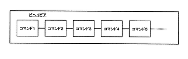
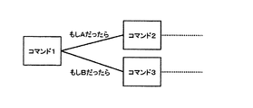
「ビヘイビア」とは、2以上のコマンドすなわちアクションを並べていくことにより構成される、移動ロボット1の振る舞いを規定するファイルである(図6を参照のこと)。アクションはスタートからエンドまで一方向で再生される。これに対して、ビヘイビアは、アクションを再生する順序を規定することができる。さらに、条件や確率に基づいた分岐や(図7を参照のこと)、複数のコマンドすなわちアクションをボックス化してサブルーチンを定義することができる(図8を参照のこと)。したがって、ビヘイビアは、アクションに比し、移動ロボット1のより高度で複雑な行動シーケンスを記述することができる。
【0100】
プロジェクトは、移動ロボット1のコンフィギュレーション(CPC:Configured Peripheral Component)と、オーサリング・システム上で制作されるビヘイビア・ファイル及びアクション・ファイルの参照リストを保持する。また、プロジェクトは、アクション・ファイルを制作するために必要な素材(コンテンツ)・ファイル(すなわち、モーション、サウンド、LED動作)の参照リストも保持する。ここで言うコンフィギュレーションとは、胴体、頭部、脚部などのロボット1の物理コンポーネントの組み合わせからなるハードウェア構成情報が設定されている。
【0101】
プロジェクト編集時には、図34に示すような「プロジェクト・ウィンドウ」が表示される。図示の通り、プロジェクト・ウィンドウ内には、ビヘイビアの編集並びにアクションの編集に使用される、ビヘイビア・ファイル、アクション・ファイル、モーション・ファイル、サウンド・ファイル、LED動作ファイルなどの各ファイルのリストがツリー形式で表示されるようになっている。
【0102】
本実施例に係るオーサリング・システムは、機能的には、モーション、サウンド、LED動作などの各コンテンツからなるコマンドすなわちアクションを編集する「アクション編集サブシステム」と、2以上のコマンドすなわちアクションを並べていくことによりロボットのビヘイビアを編集する「ビヘイビア編集サブシステム」とで構成される。
【0103】
C−1.アクション編集サブシステム
アクション編集サブシステムは、ロボットの行動シーケンスすなわちビヘイビアで使用される個々のアクションを作成・編集するためのサブシステムである。
【0104】
アクションは、アクションを実行するための時間的な長さを持ち、初期ポーズと最終ポーズを規定する。実行時間内でのロボットの動き(モーション)と、サウンドと、LED動作などを設定により、アクションが構成される。アクションを規定するファイルのことを「アクション・ファイル」と呼ぶ。アクションが使用するモーション、サウンド、LED動作などのコンテンツはファイル外からの読み込みでもよい。
【0105】
後述するように、本実施例におけるアクション編集は時間軸上に従った編集を中心としたグラフィカルなユーザ・インターフェース、すなわち「アクション・エディタ」を採用する。アクション編集の中で、モーションを規定するポーズの3D編集、サウンド、LED動作など各コンテンツの編集を行う。これらのコンテンツは時系列データであり、アクション編集サブシステムは、各コンテンツを表示するチャンネルを2次元的なタイムライン形式のタイム・テーブル上で時間軸に沿って配置して表示するようにしているので、各時系列データ間での同期を視覚的に確認しながら作成・編集することができる。
【0106】
図9には、アクション編集サブシステムの機能構成を模式的に示している。同図に示すように、本実施例に係るアクション編集サブシステムは、特にアクションの編集向けにデザインされたものであり、アクション編集部と、キーフレーム編集部と、モーション編集部と、サウンド編集部と、LED動作編集部と、これら各機能モジュールによるユーザの編集作業をGUI画面による対話形式で実現するユーザ・インターフェース制御部とで構成される。
【0107】
アクション編集部は、モーション・ファイルとサウンド・ファイルとLED動作ファイルとを時間軸上で同期がとられる形式で編集を行うための機能モジュールである。アクション編集部は、ユーザ・インターフェース制御部を介して、移動ロボット1の時間軸に沿った関節動作(モーション)と、サウンド及びLED動作のタイミングを設定するためのアクション編集ウィンドウをユーザに提示する。アクション編集ウィンドウは、各種のファイルを時間軸上で設定するためのタイムライン形式のテーブルからなる編集領域を備えている。
【0108】
キーフレーム編集部は、キーフレーム、すなわちモーションを実行する移動ロボットの該当する時刻におけるポーズを描写した画像フレームを編集するための機能モジュールである。キーフレーム編集部は、アクション編集部に対するユーザ操作に応答して呼び出され、アクション編集ウィンドウ上で開かれるキーフレーム・チャンネルを介してユーザによる編集作業を受容する。キーフレーム・チャンネルでは、時間軸上の該当する各場所にキーフレームを表すサムネイルが置かれる。
【0109】
モーション編集部は、モーションすなわち移動ロボットを構成する各関節アクチュエータの時系列的な動作を編集するための機能モジュールである。モーション編集部は、アクション編集部に対するユーザ操作に応答して呼び出され、アクション編集ウィンドウ上で開かれるモーション・チャンネルを介してユーザによる編集作業を受容する。モーション・チャンネルでは、各関節アクチュエータの時系列的な動作を記述する各タイミングチャートが、生体モデルに従ってツリー状にリストアップ(ツリー・ビュー)される。
【0110】
サウンド編集部は、アクションの構成要素の1つであるサウンドの詳細を設定するための機能モジュールである。本実施例では、サウンドは、MIDI形式又はWAVE形式で扱われる。サウンド編集部は、ユーザ・インターフェース制御部を介して、時間軸上に沿ってサウンドの詳細を設定するためのサウンド詳細ウィンドウをユーザに提示する。サウンド詳細ウィンドウは、横方向の時間軸と、縦方向のチャンネルで構成される2次元のタイムライン形式のテーブルからなる編集領域を備えている(後述)。
【0111】
LED動作編集部は、アクションの構成要素の1つであるLED動作の詳細を設定するための機能モジュールである。本実施例では、LED動作は、MIDI形式で扱われる。LED動作編集部は、ユーザ・インターフェース制御部を介して、時間軸上に沿ってLED動作の詳細を設定するためのLED詳細ウィンドウをユーザに提示する。LED詳細ウィンドウは、横方向の時間軸と、縦方向のチャンネルで構成される2次元のタイムライン形式のテーブルからなる編集領域を備えている(後述)。
【0112】
ユーザ・インターフェース制御部は、プロジェクト編集時にはプロジェクト・ウィンドウ(前述)をユーザに提示するようになっている。
【0113】
また、ユーザ・インターフェース制御部は、各編集ウィンドウを介したユーザ指示に応答して、ビヘイビア・ファイル、アクション・ファイル、モーション・ファイル,サウンド・ファイル、LED動作ファイルを管理する各ファイル・システム(又はデータベース)にアクセスできるようになっている。
【0114】
図10には、アクション編集ウィンドウの構成を概略的に示している。このアクション編集ウィンドウ上では、移動ロボット1の時間軸に沿った関節動作(モーション)と、サウンド及びLED動作のタイミングを設定することができる。
該編集ウィンドウでの編集結果は、拡張子"act"を持つアクション・ファイルとして保存される。
【0115】
図示の通り、アクション編集ウィンドウの編集領域は、横方向の時間軸と、縦方向のチャンネルで構成される2次元のタイムライン形式のテーブルである。タイムライン・テーブル内には、時間ルーラと、キーフレーム・チャンネルと、モーション・チャンネルと、サウンド・チャンネルと、LED動作チャンネルで構成される。
【0116】
時間ルーラは、単位切り替えラジオ・ボタンを利用して、実時間表示とのフレーム数表示とを切り替えることができる(図10に示す例では実時間表示が選択されている)。実時間表示の目盛の単位は、秒:ミリ秒(各2桁)表示とする。
【0117】
時間ルーラは、単位切り替えラジオ・ボタンの他に、終了時刻フィールドとカレント時刻表示フィールドを含んでいる。
【0118】
終了時刻フィールドには、編集中のアクションの終了時刻(すなわち動作時間)を示す時刻数値が表示される(図示の例では"09:40"(=9秒40)が表示されている)。また、カレント時刻表示フィールドには、カレント位置の時刻数値が表示される(図示の例では"04:60"(=4秒60)が表示されている)。これらのフィールドは編集可能なテキスト・フィールドであり、意味のある時刻数字が入力されると、それが終了時刻になって最終キーフレームが移動したり、あるいはその位置にカレント時刻が移動する。
【0119】
編集領域内では、時刻表示ラインとして、「キーフレーム・ライン」と、「最終時刻表示ライン」と、「カレント時刻ライン」がそれぞれ表示される。
【0120】
各キーフレームの時刻を示すキーフレーム・ラインが、各チャンネル上を交差する形で表示されるようにしている。したがって、ユーザは、モーション、サウンド、LED動作という各コンテンツの間での同期を目視で確認しながら編集作業を行うことができる。
【0121】
また、編集中のアクションの終了時刻を示す終了時刻ラインが各チャンネル上を交差する形で表示するようにしているので、ユーザは編集対象となる時間の範囲を視覚的に理解することができる。終了時刻ラインを最終ポーズ・キーフレーム・ラインととらえることもできる。
【0122】
また、現在時刻を示すカレント時刻ラインが各チャンネル上を交差する形で表示するようにしている。基本的に、いずれかのチャンネルの上をクリックすると、その位置にカレント時刻が移動する。
【0123】
キーフレーム・チャンネルは、時間ルーラが規定する時間軸に従ってキーフレームを表示するための領域である。
【0124】
図10に示す例では、キーフレーム・チャンネルは、開閉操作可能である。図11には、キーフレーム・チャンネルを開いた状態(キーフレーム詳細チャンネル)のアクション編集ウィンドウを示している。キーフレーム・チャンネルでは、時間軸上の該当する各場所にキーフレームを表すサムネイルが置かれる。ここで言う「キーフレーム」とは、モーションを実行する移動ロボットの該当する時刻におけるポーズを描写した画像フレームのことである。
【0125】
初期ポーズと最終ポーズは、それぞれキーフレーム・チャンネルの初めと終わりに位置する特別なキーフレームである。最初と最後のキーフレームはあらかじめ置かれている。
【0126】
キーフレーム・チャンネル上で、キーフレームが配置されていない時間では、この時間を挟む両端のキーフレームによって補間されるフレーム(以下では、「補間フレーム」とも言う)が再生されることになる。補間フレームはキーフレーム上では表示されない。本実施例に係るオーサリング・システムでは、キーフレーム・チャンネル上に各キーフレームを配置すると、各キーフレームで記述されたポーズを円滑につなぎ合わせるようなモーションが、コンピュータ処理により自動生成される。また、3Dモデルの重心を各キーフレームで設定して、3Dモデルの見た目上の動きを実機に近いものにすることができる。
【0127】
各キーフレームは、サムネイルの左端がキーフレームの時刻となるように、キーフレーム・チャンネル上に配置される。また、サムネイルを時間軸に沿って左右にドラッグすることで、キーフレームラインが追従して移動し、該当するキーフレームの時刻を変更することができる。また、最終ポーズのキーフレームの伸縮は、アクションの全体時間の伸縮となる。
【0128】
サムネイルをダブル・クリックすると、該当するポーズのポーズ編集ウィンドウが開いて、ポーズを編集することができる。但し、初期ポーズと最終ポーズは編集対象外であり、これらをダブルクリックしてもポーズ編集ウィンドウは開かない。
【0129】
モーション・チャンネルは、時間ルーラが規定する時間軸に沿ってモーションの内容を編集・表示するための領域である。
【0130】
本実施例では、モーション・チャンネルは、開閉操作可能である。図12には、モーション・チャンネルを開いた状態(モーション詳細チャンネル)のアクション編集ウィンドウを示している。モーションは、移動ロボット1を構成する各関節アクチュエータの動作によって定義される。モーション・チャンネルでは、各関節アクチュエータの時系列的な動作を記述する各タイミングチャートが、生体モデルに従ってツリー状にリストアップ(ツリー・ビュー)される。
【0131】
それぞれのタイミングチャート上の折れ線グラフは、該当する関節アクチュエータの動きすなわち回転角度の時間的変化を示している。キーフレーム・ラインと折れ線との交差するポイントを上下にドラッグすることによって、該当する関節アクチュエータの当該時間における設定値を変更することができる。また、このようなドラッグ操作の結果、キーフレーム・ラインに該当するポーズも変化し、キーフレームの内容も自動更新される。
【0132】
サウンド・チャンネルは、時間ルーラが規定する時間軸に沿ってサウンド・データを表示するための領域である。本実施例では、アクション編集ウィンドウからは独立した「サウンド詳細ウィンドウ」を開いて、該ウィンドウ上でMIDI形式のサウンド・データをGUI操作によって編集することができる。
【0133】
LED動作チャンネルは、時間ルーラが規定する時間軸に沿ってLED動作データを表示するための領域である。本実施例では、アクション編集ウィンドウからは独立した「LED詳細ウィンドウ」を開いて、該ウィンドウ上でMIDI形式のLED動作データをGUI操作で編集することができる。
【0134】
図13には、MIDI形式のサウンド・ファイルを編集するためのサウンド詳細ウィンドウの構成を概略的に示している。図示の通り、このサウンド詳細ウィンドウの編集領域は、横方向の時間軸と、縦方向のチャンネルで構成される2次元のタイムライン形式のテーブルである。タイムライン・テーブル内は、時間ルーラと、キーフレーム・チャンネルと、スコア・チャンネルと、ベロシティ・チャンネルとで構成される。
【0135】
時間ルーラは、単位切り替えラジオ・ボタンを利用して、実時間表示とのフレーム数表示とを切り替えることができる(図13に示す例では実時間表示が選択されている)。時間ルーラには、単位切り替えラジオ・ボタンの他に、終了時刻フィールドとカレント時刻表示フィールドを含んでいる。終了時刻フィールドには、編集中のアクションの終了時刻を示す時刻数値が表示され、カレント時刻表示フィールドには、カレント位置の時刻数値が表示される。これらのフィールドに意味のある時刻数字が入力されると、それが終了時刻になって最終キーフレームが移動したり、あるいはその位置にカレント時刻が移動する。
【0136】
編集領域内では、時刻表示ラインとして、「キーフレーム・ライン」と、「最終時刻表示ライン」と、「カレント時刻ライン」がそれぞれ表示される。各キーフレーム(後述)の時刻を示すキーフレーム・ラインが、各チャンネル上を交差する形で表示されており、ユーザは、キーフレームとの同期を目視で確認しながらMIDIサウンドの編集作業を行うことができる。また、編集中のアクションの終了時刻を示す終了時刻ラインが各チャンネル上を交差する形で表示するようにしているので、ユーザは編集対象となる時間の範囲を視覚的に理解することができる。また、現在時刻を示すカレント時刻ラインが各チャンネル上を交差する形で表示するようにしている。基本的に、いずれかのチャンネルの上をクリックすると、その位置にカレント時刻が移動する。
【0137】
キーフレーム・チャンネルでは、時間ルーラが規定する時間軸に沿ってアクション編集ウィンドウから取得したキーフレーム位置が表示される。
【0138】
スコア・チャンネルは、GUI操作によってMIDIサウンドを編集するための領域であり、ピアノ鍵盤(但し、移動ロボット1のモデルによってその有効音域は相違する)と、時間軸方向の基本グリッドによって構成される。
【0139】
ピアノ鍵盤では、ピアノ鍵盤のイメージ表示により移動ロボット1のハードウェア仕様などで許容される最大音域を表示するようになっている(あるいは、再生可能な音域を明るく表示し、それ以外をグレー表示するようにしてもよい)。
基本となるCキー部分には、C3、C4などの絶対音の高さを表示する
【0140】
スコア部分には、設定された四分音符の時間幅のグリッドが表示される。また、拍子で設定された値(前述)によって、2グリッド(すなわち2拍子)、3グリッド(3拍子)、4グリッド(4拍子)のラインが強調される。
【0141】
スコア・チャンネル上には、時間軸の基準となる音長と、ピアノ・キーの高さによってスコアが構成される。1つの桝目を「セル」と呼ぶ。音のあるセルには色が付く。但し、一音のみの再生モデルの場合、同じ時間軸上の異なる音階には音は置けない。また、空の(すなわち色が付いていない)セルをクリックすると、選択されている音符マークの長さの音が置かれる。同一時間上の他の高さに音が存在するとき、音はクリックされた高さに置き換わる。既に音が存在するセルがクリックされると、その音が除かれる。
【0142】
ピアノ鍵盤の左側の領域に、16分音符、八分音符、四分音符、二分音符、全音符、付点八分音符、付点四分音符、付点二分音符などの音符マークを表示しておく。これら音符マークは互いに排他的な選択状態を持ち、常にいずれか1つのみが選択されるものとする。また、マウス・クリック操作により選択アイテムが変化する。
【0143】
ベロシティ・チャンネルは、各音毎のベロシティの強さを表示する領域である。図13に示す例では、音の強さは棒グラフで表示されるが、折れ線グラフで表示してもよい。各節点での音の強さは、棒グラフの最上端をドラッグすることによった調整することができる。デフォルトでは最大音量が設定されている。
【0144】
また、図14には、WAVE形式のサウンド・ファイルを表示するためのサウンド詳細ウィンドウの構成を概略的に示している。図示の通り、サウンド詳細ウィンドウは、タイトル・バーと、メニュー・バーと、WAVE形式サウンド・ファイルの編集領域は、横方向の時間軸と、縦方向のチャンネルで構成される2次元のタイムライン形式のテーブルである。タイムライン・テーブル内は、時間ルーラと、キーフレーム・チャンネルと、WAVEチャンネルとで構成される。
【0145】
時間ルーラは、単位切り替えラジオ・ボタンを利用して、実時間表示とのフレーム数表示とを切り替えることができる。
【0146】
終了時刻フィールドには、編集中のアクションの終了時刻(すなわち動作時間)を示す時刻数値が表示される。また、カレント時刻表示フィールドには、カレント位置の時刻数値が表示される。これらのフィールドに意味のある時刻数字が入力されるとそれが終了時刻になって最終キーフレームが移動したり、あるいはその位置にカレント時刻が移動する。
【0147】
編集領域内では、時刻表示ラインとして、「キーフレーム・ライン」と、「最終時刻表示ライン」と、「カレント時刻ライン」がそれぞれ表示される。各キーフレームの時刻を示すキーフレーム・ラインが、各チャンネル上を交差する形で表示されており、ユーザは、キーフレームとの同期を目視で確認しながらWAVEサウンドの編集作業を行うことができる。また、編集中のアクションの終了時刻を示す終了時刻ラインが各チャンネル上を交差する形で表示するようにしているので、ユーザは編集対象となる時間の範囲を視覚的に理解することができる。また、現在時刻を示すカレント時刻ラインが各チャンネル上を交差する形で表示するようにしている。基本的に、いずれかのチャンネルの上をクリックすると、その位置にカレント時刻が移動する。
【0148】
キーフレーム・チャンネルでは、時間ルーラが規定する時間軸に沿ってアクション編集ウィンドウから取得したキーフレーム位置が表示される。
【0149】
WAVEチャンネルでは、図14に示すように、WAVE形式のサウンド・ファイルの中身が波形として表示される。
【0150】
また、図15には、MIDI形式で記述されたLED動作ファイルを表示して編集するためのLED詳細ウィンドウの構成を概略的に示している。図示の通り、サウンド詳細ウィンドウの編集領域は、横方向の時間軸と、縦方向のチャンネルで構成される2次元のタイムライン形式のテーブルである。タイムライン・テーブル内は、時間ルーラと、キーフレーム・チャンネルと、スコア・チャンネルとで構成される。
【0151】
時間ルーラは、単位切り替えラジオ・ボタンを利用して、実時間表示とのフレーム数表示とを切り替えることができる。時間ルーラは、単位切り替えラジオ・ボタンの他に、終了時刻フィールドとカレント時刻表示フィールドを含んでいる。終了時刻フィールドには、編集中のアクションの終了時刻を示す時刻数値が表示される。また、カレント時刻表示フィールドには、カレント位置の時刻数値が表示される。これらのフィールドに意味のある時刻数字が入力されると、それが終了時刻になって最終キーフレームが移動したり、あるいはその位置にカレント時刻が移動する。
【0152】
編集領域内では、時刻表示ラインとして、「キーフレーム・ライン」と、「最終時刻表示ライン」と、「カレント時刻ライン」がそれぞれ表示される。各キーフレームの時刻を示すキーフレーム・ラインが、各チャンネル上を交差する形で表示されており、ユーザは、キーフレームとの同期を目視で確認しながらMIDI形式で記述されたLED動作の編集作業を行うことができる。また、編集中のアクションの終了時刻を示す終了時刻ラインが各チャンネル上を交差する形で表示するようにしているので、ユーザは編集対象となる時間の範囲を視覚的に理解することができる。また、現在時刻を示すカレント時刻ラインが各チャンネル上を交差する形で表示するようにしている。基本的に、いずれかのチャンネルの上をクリックすると、その位置にカレント時刻が移動する。
【0153】
キーフレーム・チャンネルでは、時間ルーラが規定する時間軸に沿ってアクション編集ウィンドウから取得したキーフレーム位置が表示される。
【0154】
スコア・チャンネルは、GUI操作によってMIDI形式で記述されるLED動作を編集するための領域であり、移動ロボット1本体上でLEDを配置した部位のリストと、時間軸方向の基本グリッドによって構成される。本実施例では、でこ(でこぴん)と、右目αと、左目αと、右目βと、左目βと、右目γと、左目γと、しっぽαと、しっぽβの各部位にLEDが配置されている。
【0155】
スコア・チャンネル上には、時間軸上に各部位のLEDの点灯状況を表示することによって各部位リスト毎のスコアが構成される。1つの桝目を「セル」と呼ぶ。時間軸上でLEDが点灯する部位に相当する位置のセルには、その色や点灯強度に応じた色が付く。
【0156】
スコア・チャンネルの左横には、LED部位ビジュアルが表示されている。これは、変更可能なLEDの各部位をグラフィック表現したものである。
【0157】
また、LED部位ビジュアルの下方にはベロシティ・マークが表示されている。ベロシティ・マークは、上昇、最高位キープ、下降などの種類を表示したマークである。これらのマークは、互いに排他的な選択状態を持ち、常にどれか1つが選ばれている。また、マウス・クリックによって、選択アイテムが変化する。
【0158】
本実施例に係るアクション編集サブシステムは、上述のアクション編集ウィンドウ(図10を参照のこと)上で編集したアクションの内容を視覚的に確認するために、プレビュー・ウィンドウを用意している。
【0159】
図16には、プレビュー・ウィンドウの構成を概略的に示している。同図に示すように、プレビュー・ウィンドウは、「3Dビュー」と、「3D表示切り替えボタン群」と、「カレント時刻フィールド」と、「再生ボタン群」とで構成される。
【0160】
3Dビューには、コンピュータ・グラフィックス処理により生成された3次元移動ロボット1の映像が常に表示される。このビュー上でドラッグすることにより、視線方向を移動させて、ビューの見え方を変えることができる。また、図示しないが、2以上の視点から3Dモデルを同時にプレビューできるように構成してもよい。また、ビューの動きは、3D表示切り替えボタン群上でのユーザ入力操作と連動する。
【0161】
モーションの3D表示を作成処理する際に、3Dモデルにより各部位どうしの衝突(collision)や各関節の駆動速度のチェック機能を備えていてもよい。また、3Dモデルの重心を各キーフレームで設定して、3Dモデルの見た目上の動きを実機に近いものにすることができる。
【0162】
また、3Dビューの右側には、LED動作を表示するためのLED動作プレビュー領域が配設されている。このプレビュー領域では、上述した3Dビュー上の移動ロボット1の動きと同期させて、移動ロボット1のLEDが点滅する様子を表示するようになっている。
【0163】
3D表示切り替えボタン群には、「回転」、「ズームイン/アウト」、「パン」、「ホーム位置」という各ボタンが配設されている。ユーザは、これらのボタンをクリック操作することにより、3Dビュー内におけるロボットに対する視線方向を変更することができる。
【0164】
例えば、回転ボタンをクリックすると、回転モードになり、以降3Dビューをドラッグすると、3Dビュー内の移動ロボット1が回転する。また、ズームイン/アウト・ボタンをクリックすると、ズーム・モードになり、以降3Dビューを上下にドラッグすると、3Dビュー内の移動ロボット1がズームイン/アウトする。また、パン・ボタンをクリックすると、3Dビューはパン・モードになり、以降3Dビューを上下左右にドラッグすると3Dビューがパンすなわち高速移動する。また、ホーム位置ボタンをクリックすると、移動ロボット1の3次元表示がデフォルトのビューすなわちデフォルトの視線方向から見た状態に戻る。
【0165】
カレント時刻フィールドには、3Dビューに表示されている描画内容のカレント時刻が表示される。このフィールドに時刻として意味のある文字が入力されると、3Dビューの表示は該当する時刻のフレームに切り替わる。また、カレントの時刻位置を相対的にビジュアル表示するようになっている。
【0166】
再生ボタン群には、「フレームの巻き戻し」、「前のキーフレーム」、「プレイ/ストップ」、「フレームのコマ送り」、「フレーム送り」、「ループ再生」という各ボタンが配設されている。
【0167】
「フレームの巻き戻し」をクリックすると、3Dビューの表示が最初のフレームに戻る。「前のキーフレーム」をクリックすると、3Dビューの表示がカレント位置から直前のキーフレームに飛ぶ。また、「プレイ/ストップ」をクリックすると、3Dビュー表示の再生を開始又は停止する(プレイ中は、プレイ/ストップ・ボタンはストップとなり、ストップ中はプレイとして作用する)。また、「フレームのコマ送り」は、3Dビュー表示の再生中のみ有効であり、クリックされると1フレーム分がコマ送りされる。また、「フレーム送り」をクリックすると、3Dビューの表示が最後のフレームに進む。また、「ループ再生」をクリックすると、3Dビューの表示がループ再生される。
【0168】
また、本実施例に係るアクション編集サブシステムは、移動ロボット1の3次元的なポーズを、ドラッグを基調とするGUI操作により編集するためにポーズ・ウィンドウを用意している。ポーズ・ウィンドウ上で編集されるポーズは、例えば、モーションを構成するキーフレームとして利用することができる。
【0169】
図17には、ポーズ・ウィンドウの構成を概略的に示している。このポーズ・ウィンドウ上では、移動ロボット1を構成する各関節アクチュエータの回転角度をGUI操作により直接指示して、所望のポーズを簡易に指定することができる。ポーズ・ウィンドウは、実体表示領域と、リスト指定領域と、設定値領域と、3D表示領域と、3D表示切替ボタン群と、表示切り替えポップアップとで構成される。
【0170】
実体指定領域では、移動ロボット1の展開平面図を表示され編集可能部位をユーザに選択させる。選択された部位は、リスト指定の項目が選択されて、3D表示上で強調表示又はブリンクされ、設定値エリアの内容が切り替わる。
【0171】
リスト指定領域では、移動ロボット1の編集可能部位とその設定値がリストとして表示される。ユーザはこのリストの中から特定の部位を選択すると、実体指定領域では該当する部位が強調表示され、3D表示領域では強調表示又はブリンクされ、設定値領域の内容が切り替わる。
【0172】
設定値領域では、各編集可能部位の設定部位名称、設定値、設定可能最小値並びに最大値が一覧表示されている。ユーザがある特定の部位を選択するとその内容が切り替わる。設定値は、入力可能フィールドで直接キー入力することができる。角度の表現は円弧表現とし、指定用のラインをドラッグすることによって設定値を変更することができる。
【0173】
3D表示領域では、3Dグラフィックスにより生成された移動ロボット1の全身画像が地面とともに描画される。ユーザは、この3D表示から該当する部位をクリックすることにより、その部位を選択することができ、選択部位は強調表示される。さらに、選択部位をドラッグすることにより、設定値を直接切り替えることができる。
【0174】
3D表示領域における表示内容は3D表示切り替えボタンと連動しており、この3D表示領域のビュー上をドラッグすることによりビューの見え方すなわち視線方向を変えることができる。
【0175】
3D表示切り替えボタン群には、「回転」、「ズームイン/アウト」、「パン」、「ホーム位置」という各ボタンが配設されている。ユーザは、これらのボタンをクリック操作することにより、3D表示領域内の視線方向を変更することができる。
【0176】
例えば、回転ボタンをクリックすると、回転モードになり、以降3D表示領域をドラッグすると3D表示領域内の移動ロボット1が回転する。また、ズームイン/アウト・ボタンをクリックすると、ズーム・モードになり、以降3D表示領域を上下にドラッグすると3D表示領域内で移動ロボット1がズームイン/アウトする。また、パン・ボタンをクリックするとパン・モードになり、以降3D表示領域を上下左右にドラッグすると3D表示領域内で移動ロボット1がパンすなわち高速移動する。また、ホーム位置ボタンをクリックすると、移動ロボット1の3次元表示がデフォルトの視線方向から見た状態に戻る。
【0177】
ポーズ・ウィンドウには、「OK」ボタンと「キャンセル」ボタンが用意されている。OKボタンをクリックすると、該ウィンドウ内におけるすべての編集項目を有効にして、このウィンドウを閉じる。他方、キャンセル・ボタンをクリックするとすべての編集項目を無効にしてこのウィンドウを閉じる(周知)。
【0178】
また、本実施例に係るアクション編集サブシステムは、モーション・チャンネルで編集されたモーション、あるいはポーヴ・ウィンドウにより編集された各ポーズをキーフレームとしたモーションをプレビューするためのモーション・プレビューワを用意している。図18には、モーション・プレビューワの構成を概略的に示している。
【0179】
モーション・プレビューワ上では、モーションをプレビューするとともに、アクション編集ウィンドウにペーストするために、ポーズをコピーすることが許容される。
【0180】
モーション・プレビューワ上では、モーションを構成する1以上のキーフレームすなわちポーズのサムネイルを表示するようになっている。キーフレームの配列は、例えば、モーション再生時の時系列に従う。
【0181】
C−2.ビヘイビア編集サブシステム
ビヘイビア編集サブシステムは、ロボットの行動シーケンスすなわちビヘイビアを作成・編集するためのサブシステムである。
【0182】
図6〜図8を参照しながら既に説明したように、ロボットの行動シーケンスすなわちビヘイビアは、2以上のコマンドすなわちアクションを並べていくことによって構成される。アクションはスタートからエンドまで一方向で再生される。これに対して、ビヘイビアは、アクションを再生する順序を規定することができる。さらに、センサからの入力などに基づいて条件判断を実行し、アクション起動の流れを分岐させることができる。また、複数のアクションやブランチをグループ化してサブルーチンとして機能させることにより、複雑なビヘイビアの作成・編集作業を容易で効率的にすることができる。
【0183】
ビヘイビアを規定するファイルのことを「ビヘイビア・ファイル」と呼ぶ。ビヘイビアにおいて使用するアクションの内容を、ファイル参照しても、あるいは読み込むようにしてもよい。
【0184】
本実施例におけるビヘイビア編集サブシステムは、使用するアクションを部品化してマウス操作により取り扱うことができるグラフィカルなユーザ・インターフェース、すなわち「ビヘイビア・エディタ」を採用する。ビヘイビアはその部品である2以上のアクションを配列することによって構成されることから、ビヘイビア・エディタは、外見的にはフローチャート・エディタの形式を採用する。ビヘイビア・エディタ画面上では、アクション間の連結に条件判断を形成したり、ループを形成したり、複数のアクションの配列をグループ化し部品として定義することができる。但し、ビヘイビア・エディタが提供するビヘイビア編集画面の詳細については、後述に譲る。
【0185】
図19には、ビヘイビア編集サブシステムの機能構成を模式的に示している。
同図に示すように、本実施例に係るビヘイビア編集サブシステムは、特にビヘイビアの編集向けにデザインされたものであり、ビヘイビア編集部と、これら各機能モジュールによるユーザの編集作業をGUI画面による対話形式で実現するユーザ・インターフェース制御部とで構成される。
【0186】
ビヘイビア編集部は、アクション編集サブシステムにおいて作成されたアクションを部品として、複数のアクションを配列することにより(図6〜8を参照のこと)、1つのビヘイビアを完成させる。
【0187】
ビヘイビア編集部は、意図する動作すなわちアクションを表すボックスをライブラリから選択することができる。ライブラリからのアクションの選択はアクション選択部を介して行われる。アクション選択部の起動により、画面上にはアクション設定ウィンドウがポップアップ表示される。アクション設定ウィンドウ(後述)上では、アクションの詳細を対話形式で指定することができる。指定されたアクションは、編集画面上ではボックスとして配置される。
【0188】
複数のアクションの配列をグループ化して、部品として定義する場合には、グループ登録部を呼び出すことによって行われる。グループ登録部の起動により、画面上にはグループ設定ウィンドウがポップアップ表示され、グループの詳細を対話形式で指定することができる。グループは、グループ登録部を介してライブラリ内に登録され、以後はアクションと同様に、ビヘイビアを構成する部品として取り扱うことができ、編集画面上ではボックスとして表示される。
【0189】
ビヘイビアは、アクションどうしの単なる連結の他、後続の複数のアクションへの分岐並びに分岐のための条件判断を含んだり、アクションのループを形成することができる。
【0190】
アクションを接続する場合、接続側並びに被接続側それぞれのアクションに対して接続用の端子を形成する。端子の形成は、端子設定部によって行われる。端子設定部を起動することにより、編集画面上では端子設定ウィンドウがポップアップ表示され、端子の詳細を指定することができる。また、ビヘイビア編集画面上では、ボックスの端子どうしをドラッグすることにより該当するアクションどうしを連結することができる。
【0191】
あるアクションが複数のアクションへの分岐を設定する場合、分岐設定部を呼び出す。分岐設定部の起動により、編集画面上には分岐設定ウィンドウがポップアップ表示され、分岐の詳細を指定することができる。
【0192】
あるアクションが後続のアクションへ進むための条件を設定する場合、条件設定部を呼び出す。条件設定部の起動により、編集画面上には条件設定ウィンドウがポップアップ表示され、条件判断の詳細を指定することができる。
【0193】
ユーザ・インターフェース制御部によって、ビヘイビア編集ウィンドウがコンピュータ画面上に提示される。このビヘイビア編集ウィンドウ上では、基本的には、ビヘイビアの構成要素であるアクションを表すボックスを、分岐端子を用いて接続していくことにより、全体としてある所定の機能を実現するプログラムを組むことができる。接続関係が形成された複数のアクションをグループとして登録し、グループを表すボックスを、アクション・ボックスと同様に部品化して、ビヘイビア編集ウィンドウ上で取り扱うことができる。ビヘイビア編集ウィンドウは、外見上はフローチャート・エディタの形式を採用する。
【0194】
図20には、ビヘイビア編集ウィンドウの構成を概略的に示している。
【0195】
図示の通り、ビヘイビア編集ウィンドウは、タイトル・バーと、メニュー・バーと、ツール・バーと、アクションやグループを分岐端子によって接続してフローチャート編集様式でプログラムを編集することができる編集領域とで構成される。
【0196】
メニュー・バーには「ファイル」、「編集」、「オブジェクト」、「ツール」、「表示倍率」、「ヘルプ」という各メニューが用意されている。
【0197】
メニュー「ファイル」を選択すると、さらに「新規ビヘイビア」、「ビヘイビアを開く」、「ビヘイビア保存」、「ビヘイビア新規保存」、並びに、「閉じる」という各サブ・メニューからなるプルダウン・メニューが出現する(図21を参照のこと)。
【0198】
サブメニュー「新規ビヘイビア」を選択すると、新規のビヘイビアを生成する。既に未保存のアクションが開かれている場合、そのビヘイビアを保存するかどうかの確認をユーザにプロンプトするダイアログ(図示しない)が出現する。
【0199】
サブメニュー「ビヘイビアを開く」を選択すると、既存のビヘイビア・ファイルを開く。既に未保存のビヘイビアが開かれている場合、そのビヘイビアを保存するかどうかの確認をユーザにプロンプトするダイアログが出現する(同上)。
【0200】
サブメニュー「ビヘイビア保存」を選択すると、該当するビヘイビア・ファイルを上書き保存する。未保存ファイルの場合、ビヘイビア新規保存(後述)と同様、ファイル設定ダイアログが出現して、ファイル名の入力をユーザにプロンプトする。
【0201】
サブメニュー「ビヘイビア新規保存」を選択すると、ファイル設定ダイアログ(図示しない)が出現して、ファイル名の入力をユーザにプロンプトする。
【0202】
サブメニュー「閉じる」を選択すると、起動中のビヘイビア編集ウィンドウを閉じる。該ウィンドウ内のビヘイビア・ファイルが未保存の場合には、ダイアログが出現して、これを保存するかどうかの確認をユーザにプロンプトする(同上)。
【0203】
また、メニュー「編集」を選択すると、さらに「元に戻す」、「切り取り」、「コピー」、「上書き貼り付け」、「挿入貼り付け」、並びに、「削除」という各サブ・メニューからなるプルダウン・メニューが出現する(図22を参照のこと)。
【0204】
サブメニュー「元に戻す」を選択すると、直近の操作から順にアンドゥー処理が行われる。
【0205】
サブメニュー「切り取り」を選択すると、選択されたオブジェクトがカットされる。カットされたデータは、実際にはクリップボード内に一時的に保管される。
【0206】
サブメニュー「コピー」を選択すると、選択されたオブジェクトがコピーされる。コピーされたデータは、実際にはクリップボード内に一時的に保管される。
【0207】
サブメニュー「上書き貼り付け」を選択すると、クリップボードに保管されているオブジェクトがビヘイビア編集領域上にペーストされる。
【0208】
サブメニュー「削除」を選択すると、選択されたオブジェクトが削除される。
【0209】
メニュー「オブジェクト」は、ビヘイビア編集領域上に、プログラム編集用の部品となるオブジェクトを置いたり、設置したオブジェクトに対する操作を行うための機能を提供する。プログラム編集用の部品とは、ボックス化されたアクション、ブランチ、グループ、あるいはこれらボックス間を接続するためのターミナル(分岐端子)である。これらオブジェクトは、フローチャートの構成要素となる。
【0210】
メニュー「オブジェクト」を選択すると、さらに「アクションを置く」、「新規ブランチを置く」、「新規グループを置く」、「新規ターミナルを置く」、並びに、「プロパティ」という各サブ・メニューからなるプルダウン・メニューが出現する(図23を参照のこと)。
【0211】
サブメニュー「アクションを置く」を選択すると、ファイル選択ダイアログ(図示しない)が出現して、アクション・ファイルの選択をユーザにプロンプトする。選択されたアクションは、オブジェクトすなわち「アクション・ボックス」として、ビヘイビア編集領域上に置かれる。そのアクションは、同時に自動的にプロジェクト・ウィンドウ(前述)に登録される。
【0212】
サブメニュー「新規ブランチを置く」を選択すると、新規のブランチを生成して、これに対応するオブジェクトすなわち「ブランチ・ボックス」をビヘイビア編集領域上に置く。新規のブランチにはデフォルトの名前が付けられ、ユーザはこれを適当な名前に変更することができる。
【0213】
サブメニュー「新規グループを置く」を選択すると、新規のグループを生成して、これに対応するオブジェクトすなわち「グループ・ボックス」をビヘイビア編集領域上に置く。新規のグループにはデフォルトの名前が付けられ、ユーザはこれを適当な名前に変更することができる。
【0214】
サブメニュー「新規ターミナルを置く」を選択すると、新規のターミナルを生成して、これをビヘイビア編集領域上に置く。新規のターミナルにはデフォルトの名前が付けられ、ユーザはこれを適当な名前に変更することができる。
【0215】
サブメニュー「プロパティ」を選択すると、選択されているオブジェクトのプロパティ・ダイアログが出現する。ユーザは、このダイアログ内で該当するオブジェクトのプロパティを設定することができる。但し、プロパティ・ダイアログに関しては後述する。
【0216】
なお、オブジェクト・メニューの各サブメニュー項目と同様の機能は、ツール・バー(後述)上でも提供される。
【0217】
メニュー「ツール」は、「アローツール」、「結線ツール」、「線切りツール」などのサブメニューを用意する。各サブメニューを用意すると、該当する機能が呼び出される。これらサブメニューと同じ機能は、ツール・バー上のツール・ボックスとして配設されている(後述)。
【0218】
また、メニュー「表示倍率」は、ビヘイビア編集領域の表示倍率を選択するためのメニュー項目である。本実施例では、1/4,1/2,等倍,2倍,4倍,8倍を選択肢として用意している。
【0219】
また、メニュー「ヘルプ」には、トピックやサポート・ウェブ、バージョン情報などのサブメニューが含まれている(周知)。
【0220】
ツール・バー内には、「アローツール」、「結線ツール」、「線切りツール」、「ルーペ」、「ごみ箱」などの頻繁に使用する機能を瞬時に呼び出すためのツール・ボックスと、「アクション」、「グループ」、「ブランチ」、「ターミナル」などのビヘイビア編集領域に置くべき部品すなわちオブジェクトを呼び出すためのオブジェクト・ボックスが配設されている。
【0221】
ツール・ボックス「アローツール」を指定すると、ビヘイビア編集領域内におけるマウス操作が、通常モード、すなわちオブジェクトを移動させるモードになる。
【0222】
ツール・ボックス「結線ツール」を指定すると、ビヘイビア編集領域内におけるマウス操作が、結線モード、すなわちオブジェクトどうしを結線するモードになる。
【0223】
ツール・ボックス「線切りツール」を指定すると、ビヘイビア編集領域以内におけるマウス操作が、線切りモード、すなわちオブジェクト間の結線を切断するモードになる。
【0224】
ツール・ボックス「ルーペ」を指定すると、マウスがクリックされた時点を一段階ずつ拡大表示する。また、コントロール・キーを押下しながらルーペをクリックすると、一段階ずつ縮小表示する。表示倍率範囲は、メニュー「表示倍率」内で用意されるサブメニュー項目(前述)に従う。
【0225】
ツール・ボックス「ごみ箱」を指定すると、マウスがクリックされたオブジェクトをビヘイビア編集領域から削除することができる。
【0226】
各ツール・ボックス「アローツール」、「結線ツール」、「線切りツール」、「ルーペ」は、排他的に選択される。
【0227】
ボックス「アクション」をツール・バーからビヘイビア編集領域内にドラッグすることにより、ドラッグ先には新規のアクション・ボックスが置かれる。これと同時に、この新規アクションの詳細を設定するためのプロパティ・ダイアログが画面上に出現する。
【0228】
図24には、アクション・ボックスの詳細を指定するためのプロパティ・ダイアログを図解している。このアクション設定用のプロパティ・ダイアログは、ツール・バー内のアクション・ボックスをビヘイビア編集領域にドラッグすることによって呼び出される他、メニュー「オブジェクト」のサブメニュー項目「プロパティ」を経由して起動することができる。
【0229】
ユーザは、図示のダイアログ上で、名前フィールドに文字列を入力することによってアクション・ボックスの名前を指定することができる。また、コメント・フィールド上に、このアクション・ボックスに関するコメントを記入することができる。
【0230】
さらに、Action、Part、Sound、Volume#などのコンボボックス内に、RCODEのコマンド名やコマンド・パラメータを直接入力するか、又は、該ボックスの右端の▼ボタンを押して出現するリスト・ボックス(図示しない)から所望のコマンド又はコマンド・パラメータを選択することによって、1行すなわち1ステップ分のRCODEコマンドを設定することができる。
【0231】
これらAction、Part、Sound、Volume#などのコンボボックスを利用して1ステップ分のRCODEコマンドを設定し、さらに[追加(A)]ボタンをクリックすると、コマンド・リスト上に順次登録される。
【0232】
また、このコマンド・リスト上で所定の行を選択してから、[変更(M)]ボタンをクリックすることによって、当該行は変更対象となり、その設定内容がAction、Part、Sound、Volume#などの各コンボボックスに表示される。また、このコマンド・リスト上で所定の行を選択してから、[削除(D)]ボタンをクリックすることによって、当該行をコマンド・リストから削除することができる。
【0233】
そして、このダイアログ上で動作ボックスの詳細の指定を完了すると、[閉じる(C)]ボタンをクリックすることによって、画面を介した指定内容がRCODEで記述された処理ルーチンとして登録されるとともに、このダイアログは閉じる。
【0234】
また、ボックス「ブランチ」をツール・バーからビヘイビア編集領域内にドラッグすることにより、ドラッグ先には新規のブランチ・ボックスが置かれる。これと同時に、この新規ブランチの詳細を設定するためのプロパティ・ダイアログが画面上に出現する。
【0235】
図25には、ブランチ・ボックスの詳細を指定するためのプロパティ・ダイアログを図解している。このブランチ設定用のプロパティ・ダイアログは、ツール・バー内のブランチ・ボックスをビヘイビア編集領域にドラッグすることによって呼び出される他、メニュー「オブジェクト」のサブメニュー項目「プロパティ」を経由して起動することができる。
【0236】
ユーザは、図示のダイアログ上で、名前フィールドに文字列を入力することによってブランチ・ボックスの名前を指定することができる。図示の例では、当該分岐ボックスの名前として「モード分岐」が記入されている。また、コメント・フィールド上に、該ブランチ・ボックスに関するコメントを記入することができる。
【0237】
さらに、Type、Variableなどのコンボボックス内に、RCODEのコマンド名やコマンド・パラメータを直接入力するか、又は、該ボックスの右端の▼ボタンを押して出現するリスト・ボックス(図示しない)から所望のコマンド又はコマンド・パラメータを選択することによって、当該分岐ボックスの条件判断を記述するRCODEコマンドを設定することができる。
【0238】
これらType、Variableなどのコンボボックスを利用して分岐条件のRCODEコマンドを設定し、さらに[追加(A)]ボタンをクリックすると、コマンド・リスト上に順次登録される。
【0239】
また、このコマンド・リスト上で所定の行を選択してから、[変更(M)]ボタンをクリックすることによって、当該行は変更対象となり、その設定内容がType、Variableなどの各コンボボックスに表示される。また、このコマンド・リスト上で所定の行を選択してから、[削除(D)]ボタンをクリックすることによって、当該行をコマンド・リストから削除することができる。
【0240】
そして、このダイアログ上でブランチ・ボックスの詳細の指定を完了すると、[閉じる(C)]ボタンをクリックすることによって、指定内容がRCODEで記述された処理ルーチンとして登録されるとともに、ダイアログは閉じる。
【0241】
ブランチ・ボックスを利用することにより、センサ入力やユーザ変数値に応じて処理を分岐させることができる。
【0242】
また、ボックス「グループ」をツール・バーからビヘイビア編集領域内にドラッグすることにより、ドラッグ先には新規のグループ・ボックスが置かれる。これと同時に、この新規グループの詳細を設定するためのプロパティ・ダイアログが画面上に出現する。
【0243】
図26には、グループ・ボックスの詳細を指定するためのプロパティ・ダイアログを図解している。このグループ設定用のプロパティ・ダイアログは、ツール・バー内のアクション・ボックスをビヘイビア編集領域にドラッグすることによって呼び出される他、メニュー「オブジェクト」のサブメニュー項目「プロパティ」を経由して起動することができる。
【0244】
同図に示すダイアログ上では、グループ名と、ビヘイビア編集領域内でグループ・ボックスに与えられる(表示される)名前を設定することができる。
【0245】
また、ボックス「ターミナル」をツール・バーからビヘイビア編集領域内にドラッグすることにより、ドラッグ先には新規のターミナル・ボックスが置かれる。これと同時に、この新規ターミナルの詳細を設定するためのプロパティ・ダイアログが画面上に出現する。
【0246】
図27には、ターミナル・ボックスの詳細を指定するためのプロパティ・ダイアログを図解している。このターミナル設定用のプロパティ・ダイアログは、ツール・バー内のターミナル・ボックスをビヘイビア編集領域にドラッグすることによって呼び出される他、メニュー「オブジェクト」のサブメニュー項目「プロパティ」を経由して起動することができる。同図に示すダイアログ上では、ターミナルに与えられる(表示される)名前を設定することができる。
【0247】
ツール・バー内の結線ツールをクリックすることにより、ビヘイビア編集領域内の各ボックス間を接続することができることは既に述べた通りである。ボックス間を接続する際には接続の許可/不許可を判断するための条件を設定することができる。判断条件を設定したい場合には、条件(Condition)を設定するためのダイアログを呼び出せばよい。
【0248】
図28には、接続条件の詳細を指定するためのプロパティ・ダイアログを図解している。この条件設定用のプロパティ・ダイアログは、例えば、メニュー「オブジェクト」のサブメニュー項目「プロパティ」を経由して起動することができる。このダイアログ内では、論理積(AND)、論理和(OR)などを用いた複数の条件(図示の例では最大4個の条件)の組み合わせを接続条件として設定することができる。
【0249】
次いで、ビヘイビア編集領域内でのプログラム編集処理について説明する。
【0250】
該編集領域内では、各オブジェクトのドラッグ・アンド・ドロップ操作が許容されている。アクションやグループ、ブランチなどの各オブジェクトは「ボックス」という形式で部品化されており、ユーザは、各ボックスやボックス間のドラッグ・アンド・ドロップ操作により、ボックス間の接続や切断を繰り返す作業を通じて、ボックスの連結関係により記述される、全体としてある機能を実現するプログラムを組むことができる。編集作業は、外見上はフローチャート・エディタの形式を採用する。
【0251】
図20に示したような新規ビヘイビア編集ウィンドウ上で、ターミナル・ボックスのドラッグ・アンド・ドロップ操作により、プログラムやルーチンの開始を示す端子"START"、並びに、プログラムやルーチンの終了を示す端子"RETURN"を置くことができる(図29)。
【0252】
ターミナル・ボックスをビヘイビア編集領域上にドロップすることに連動して、図27に示したようなプロパティ・ダイアログが起動して、端子の詳細を設定することができる。
【0253】
RETURNは、プログラムやルーチンの出力端子を意味し、図示の通り、1つのプログラムやルーチンが複数の出力端子を備えていてもよい。
【0254】
アクション・ボックスやブランチ・ボックスを、ツール・バーからビヘイビア編集領域にドラッグ・アンド・ドロップすることによって、ビヘイビア編集領域上にアクション・ボックス並びにブランチ・ボックスを置くことができる。この際、アクションやブランチの詳細を設定するためのプロパティ・ダイアログ(図24及び図25を参照のこと)がポップアップ表示される。各プロパティ・ダイアログ上で、アクション・ボックスに割り当てるアクションの名前を指定したり、グループ・ボックスに割り当てるグループの名前を指定したり、新規ブランチ・ボックスに名前を与えたりすることができる。図30には、ビヘイビア編集領域上に、アクション・ボックスやグループ・ボックスブランチ・ボックスを配置した様子を示している。
【0255】
図30に示すように各ボックスは、ボックス名が表示されたボックス本体と、このボックス本体の上端に隣接するボックスの入力端子部と、ボックス本体の下端に隣接する出力端子部とで構成される。
【0256】
さらに、ツール・バー内の結線ツールをクリックすることにより、ビヘイビア編集領域は結線モードとなる。この動作モード下では、あるボックスの出力端子部と他のボックスの入力端子部の間をドラッグ操作することによって、ボックス間の接続関係を形成することができる。
【0257】
ボックス間を接続する際には接続の許可/不許可を判断するための条件を設定することができる。判断条件を設定したい場合には、条件(Condition)を設定するためのダイアログ(図28を参照のこと)を呼び出せばよい。
【0258】
図31には、ビヘイビア編集領域上に配置されたアクション・ボックスやグループ・ボックスブランチ・ボックスなどの各ボックス間に接続関係を形成した様子を示している。
【0259】
使用するボックスの配置並びに各ボックス間の接続関係を設定することによって、ビヘイビア編集領域上では、ある所定の機能を実現するプログラム又はプログラムの一部を構成するルーチンが組まれたことになる。ビヘイビア編集領域上では、プログラムやルーチンはフローチャートに類似した形式で表示されるので、ユーザは、フローチャートを編集する形式で、所望のプログラムやルーチンを比較的容易且つ直感的に編集することができる訳である。
【0260】
ビヘイビア編集領域上でフローチャート状に組まれたルーチンをグループとして登録することにより、これをアクションや既存のグループなどと同様に部品すなわちオブジェクトとして扱うことが可能となる。例えば他の(上位の)プログラムやルーチンを構築する際に、新たに登録したグループを使用することができる。
【0261】
例えば、図31に示したようなビヘイビア編集領域上で形成されたプログラム又はルーチンをグループ化することもできる。
【0262】
図32には、図31に示したビヘイビア編集領域上で形成されたプログラム又はルーチンをグループ化したグループ・ボックスをビヘイビア編集領域に配置した様子を示している。例えば、このグループに対して"Group_012"なるグループ名を与えたとする。図31からも分かるように、Group_012は、1個の入力端子と3個の出力端子を備えている。
【0263】
ビヘイビア編集領域上にアクションやグループ、ブランチなど他のオブジェクト・ボックスを配置して、これらボックスとGroup_012とを端子で接続することにより、Group_012を部品の一部すなわちルーチンとして利用したプログラム(図示しない)を組むことができる。
【0264】
また、一旦編集・登録したグループの詳細をビヘイビア編集領域に開いて、さらに編集作業を行うことができる。図33には、図32に示したグループ・ボックスを開いた様子を図解している。
【0265】
[追補]
以上、特定の実施例を参照しながら、本発明について詳解してきた。しかしながら、本発明の要旨を逸脱しない範囲で当業者が該実施例の修正や代用を成し得ることは自明である。
【0266】
本実施例では、イヌを模した4足歩行を行うペット型ロボットを例に挙げて本発明に係るオーサリング・システムについて詳解したが、本発明の要旨はこれに限定されない。例えば、ヒューマノイド・ロボットのような2足の脚式移動ロボットや、あるいは脚式以外の移動型ロボットに対しても、同様に本発明を適用することができることを充分理解されたい。
【0267】
また、本明細書の[特許請求の範囲]の欄に記載される「多関節構造体」は、脚式ロボットを始めとする多関節型ロボットのような物理的な機械装置には限定されない。例えば、コンピュータ・グラフィックスにより生成されるキャラクタを用いたアニメーションの動作シーケンスの作成・編集のために、本発明に係るオーサリング・システムを適用することも可能である。
【0268】
要するに、例示という形態で本発明を開示してきたのであり、限定的に解釈されるべきではない。本発明の要旨を判断するためには、冒頭に記載した特許請求の範囲の欄を参酌すべきである。
【0269】
【発明の効果】
以上詳記したように、本発明によれば、所定のシナリオに従ったデータの作成・編集を支援することができる、優れたオーサリング・システム及びオーサリング方法を提供することができる。
【0270】
また、本発明によれば、ロボットの所定の動作パターンを記述する一連のコマンド/データの作成・編集を支援することができる、優れたオーサリング・システム及びオーサリング方法を提供することができる。
【0271】
また、本発明によれば、ロボットの動作状態を規定する部品の集合を用いて動作パターンの作成・編集を支援することができる、優れたオーサリング・システム及びオーサリング方法を提供することができる。
【0272】
また、本発明によれば、各関節アクチュエータの動作など1以上の時系列データの組み合わせからなるロボットのアクションを部品化してコンピュータ・ディスプレイ上に配置するとともに、各アクションの結合関係をディスプレイ上のGUI操作により規定することでロボットのビヘイビアの作成・編集を行うことができる、優れたオーサリング・システム及びオーサリング方法を提供することができる。
【0273】
本発明に係るオーサリング・システム及びオーサリング方法によれば、ロボットを始めとする多関節構造体を新しい遊びとして扱うことができるツールを提供することができる。本発明によれば、コンピュータ・プログラミングに関する高度な知識がなくとも、ロボットを始めとする多関節構造体の行動をプログラムすることができ、簡単にコンテンツを作成することができる。例えば、ユーザは、多関節構造体を表現するためのツールとして使用することができ、言い換えれば、ロボットが提供するワールドを拡張することができる。
【0274】
本発明に係るオーサリング・システム及びオーサリング方法によれば、ユーザは、GUI操作を介して、フローチャート・エディタ形式で多関節構造体の行動シーケンスに関するプログラミングを行うことができる。さらに、ライブラリを豊富に取り揃えることによって、GUI画面上でのプログラミング作業をさらに簡単で効率的なものにすることができる。
【図面の簡単な説明】
【図1】本発明を実施に供される四肢による脚式歩行を行う移動ロボット1の外観構成を示した図である。
【図2】移動ロボット1の電気・制御系統の構成図を模式的に示した図である。
【図3】制御部20の構成をさらに詳細に示した図である。
【図4】ホスト・コンピュータ100のハードウェア構成例を模式的に示した図である。
【図5】本実施例に係るオーサリング・システムの全体構成を模式的に示した図である。
【図6】2以上のコマンドすなわちアクションを並べていくことによりロボットのビヘイビアを構成する様子を示した図である。
【図7】条件や確率に基づいた分岐をビヘイビアの中に含めた様子を示した図である。
【図8】複数のコマンドすなわちアクションをボックス化してサブルーチンを定義した様子を示した図である。
【図9】アクション編集サブシステムの機能構成を模式的に示したブロック図である。
【図10】アクション編集ウィンドウの構成を概略的に示した図である。
【図11】キーフレーム・チャンネルを開いた状態(キーフレーム詳細チャンネル)のアクション編集ウィンドウを示した図である。
【図12】モーション・チャンネルを開いた状態(モーション詳細チャンネル)のアクション編集ウィンドウを示した図である。
【図13】MIDI形式のサウンド・ファイルを編集するためのサウンド詳細ウィンドウの構成を概略的に示した図である。
【図14】WAVE形式のサウンド・ファイルを表示するためのサウンド詳細ウィンドウの構成を概略的に示した図である。
【図15】MIDI形式で記述されたLED動作ファイルを表示して編集するためのLED詳細ウィンドウの構成を概略的に示した図である。
【図16】プレビュー・ウィンドウの構成を概略的に示した図である。
【図17】ポーズ・ウィンドウの構成を概略的に示した図である。
【図18】モーション・プレビューワの構成を概略的に示した図である。
【図19】ビヘイビア編集サブシステムの機能構成を模式的に示した図である。
【図20】ビヘイビア編集ウィンドウの構成を概略的に示した図である。
【図21】ビヘイビア編集ウィンドウ内のメニュー「ファイル」のサブメニュー項目を示した図である。
【図22】ビヘイビア編集ウィンドウ内のメニュー「編集」のサブメニュー項目を示した図である。
【図23】ビヘイビア編集ウィンドウ内のメニュー「オブジェクト」のサブメニュー項目を示した図である。
【図24】アクション・ボックスの詳細を指定するためのプロパティ・ダイアログを示した図である。
【図25】ブランチ・ボックスの詳細を指定するためのプロパティ・ダイアログを示した図である。
【図26】グループ・ボックスの詳細を指定するためのプロパティ・ダイアログを示した図である。
【図27】ターミナル・ボックスの詳細を指定するためのプロパティ・ダイアログを示した図である。
【図28】条件判断の詳細を指定するためのプロパティ・ダイアログを示した図である。
【図29】ビヘイビア編集領域上にターミナルを置いた様子を示した図である。
【図30】ビヘイビア編集領域上にアクション・ボックスやブランチ・ボックスを配置した様子を示した図である。
【図31】ビヘイビア編集領域上に配置されたアクション・ボックスやグループ・ボックスブランチ・ボックスなどの各ボックス間に接続関係を形成した様子を示した図である。
【図32】図31に示したビヘイビア編集領域上で形成されたプログラム又はルーチンをグループ化したグループ・ボックスをビヘイビア編集領域に配置した様子を示した図である。
【図33】図32に示したグループ・ボックスを開いた様子を示した図である。
【図34】プロジェクト・ウィンドウを示した図である。
【符号の説明】
1…移動ロボット
2…胴体部ユニット
3…頭部ユニット
4…尻尾
6A〜6D…脚部ユニット
7…首関節
8…尻尾関節
9A〜9D…大腿部ユニット
10A〜10D…脛部ユニット
11A〜11D…股関節
12A〜12D…膝関節
15…CCDカメラ
16…マイクロフォン
17…スピーカ
18…タッチセンサ
19…LEDインジケータ
20…制御部
21…CPU
22…RAM
23…ROM
24…不揮発メモリ
25…インターフェース
26…無線通信インターフェース
27…ネットワーク・インターフェース・カード
28…バス
29…キーボード
40…入出力部
50…駆動部
51…モータ
52…エンコーダ
53…ドライバ[0001]
BACKGROUND OF THE INVENTION
The present invention relates to an authoring system and authoring method for supporting creation / editing of data according to a predetermined scenario, and more particularly, to create / edit a series of commands / data describing a predetermined operation pattern of a robot. The present invention relates to an authoring system and an authoring method to be supported.
[0002]
More particularly, the present invention relates to an authoring system and authoring method for supporting creation / editing of motion patterns using a set of parts that define the motion state of a robot. Robot actions consisting of a combination of time-series data are converted into parts and placed on a computer display, and the behavior of the robot can be created and edited by defining the connection relationship of each action by GUI operation on the display The present invention relates to an authoring system and authoring method.
[0003]
[Prior art]
A mechanical device that uses an electrical or magnetic action to perform a movement resembling human movement is called a “robot”. The origin of the robot is said to be derived from the Slavic word ROBOTA (slave machine). In Japan, robots began to spread from the end of the 1960s, but many of them are industrial robots such as manipulators and transfer robots for the purpose of automating and unmanned production operations in factories. Met.
[0004]
Recently, a pet-type robot that mimics the body mechanism and movement of a quadruped animal, such as a dog or a cat, or the body mechanism or movement of a biped upright animal such as a human or monkey. Research and development on the structure of legged mobile robots and their stable walking control, such as “humanoid” or “humanoid robot”, has progressed, and expectations for practical use are also increasing. These legged mobile robots are more unstable than crawler robots, making posture control and walking control difficult, but are superior in that they can realize flexible walking and running operations such as climbing stairs and climbing obstacles. Yes.
[0005]
A stationary type robot such as an arm type robot that is implanted and used in a specific place operates only in a fixed / local work space such as an assembly / sorting operation of parts. In contrast, a mobile robot has a non-restricted working space, and can freely move on a predetermined route or a non-route to perform a predetermined or arbitrary human work, or a human or dog. Alternatively, various services that replace other life forms can be provided.
[0006]
One of the uses of legged mobile robots is to perform various difficult operations in industrial activities and production activities. For example, maintenance work at nuclear power plants, thermal power plants, petrochemical plants, transportation and assembly work of parts at manufacturing plants, cleaning of high-rise buildings, substitution of dangerous work and difficult work such as rescue at fire sites etc. .
[0007]
Further, as other uses of the legged mobile robot, rather than the above-described work support, there is a life-contact type, that is, a “symbiosis” or “entertainment” with a human. This kind of robot emulates the movement mechanism of legged walking animals such as humans and dogs (pets) and rich emotional expressions using limbs. In addition to simply executing the pre-input motion pattern faithfully, a lively response that dynamically responds to the opponent's words and attitudes (such as “praise”, “speak”, “slap”, etc.) Realization of expression is also required.
[0008]
In the conventional toy machine, the relationship between the user operation and the response operation is fixed, and the operation of the toy cannot be changed according to the user's preference. As a result, the user eventually gets bored with the toy that repeats only the same action.
[0009]
In contrast, intelligent robots are equipped with behavioral models and learning models due to movement, and by changing the model based on input information such as voice, images, and touch from outside, Realize autonomous thinking and motion control. By preparing an emotion model and instinct model, the robot can express autonomous behavior according to the emotion and instinct of the robot itself. In addition, robots equipped with image input devices and voice input / output devices and performing image recognition processing and voice recognition processing can realize realistic communication with humans at a higher intelligent level. .
[0010]
In addition, by changing this model in response to detection of external stimuli such as user operations, that is, by providing a “learning effect”, it is possible to provide an operation pattern that does not get bored or adapts to preferences Can do.
[0011]
Recent legged mobile robots have high information processing capabilities, and the robot itself can be regarded as a kind of computer system. Therefore, a high-level and complicated series of motion sequences configured by motion patterns realized on a robot or a combination of a plurality of basic motion patterns is constructed by operations similar to computer programming.
[0012]
In addition, the penetration rate of robots is expected to increase further in the future, and it is expected that robots will deeply penetrate not only in the industrial world but also in general households and daily life. In particular, for products that pursue entertainment, it is expected that there are many cases where general consumers who do not have advanced knowledge of computers and computer programming purchase and use robots.
[0013]
Therefore, it is preferable for such a general user to provide a tool for supporting creation and editing of a robot operation sequence relatively easily and efficiently by interactive processing, that is, an authoring system. Conceivable.
[0014]
[Problems to be solved by the invention]
An object of the present invention is to provide an excellent authoring system and authoring method capable of supporting data creation / editing according to a predetermined scenario.
[0015]
A further object of the present invention is to provide an excellent authoring system and authoring method capable of supporting creation / editing of a series of commands / data describing a predetermined motion pattern of a multi-joint structure such as a robot. There is.
[0016]
A further object of the present invention is to provide an excellent authoring system and authoring method that can support creation / editing of motion patterns using a set of parts that define the motion state of a robot.
[0017]
A further object of the present invention is to make a robot action consisting of a combination of one or more time-series data such as the operation of each joint actuator as a component and place it on a computer display, and to show the connection relationship of each action on the GUI on the display. It is an object of the present invention to provide an excellent authoring system and authoring method capable of creating and editing a robot behavior by specifying the operation.
[0018]
[Means and Actions for Solving the Problems]
The present invention has been made in consideration of the above problems, and a first aspect thereof is an authoring system or method for supporting creation / editing of a behavior of an articulated structure,
A user input unit or step for receiving commands and data input from the user via the operation screen;
A user presenting unit or step for providing a work place for creating and editing the behavior of the other joint structure to the user on the operation screen;
A program generation unit or a step for generating a program for defining a behavior by forming a connection relationship between behavioral components based on a user input on the operation screen;
An authoring system or method comprising:
[0019]
However, “system” here refers to a logical collection of a plurality of devices (or functional modules that realize specific functions), and each device or functional module is in a single housing. It does not matter whether or not.
[0020]
In addition, the behavioral component can include an action, a group in which a plurality of actions are combined, a branch, and a termination.
[0021]
The action includes motion data describing the time-series operation of each joint of the multi-joint structure, sound data output in synchronization with the playback of the action, and the playback and time of the action. The indicator display data describing the lighting / extinguishing operation of the display indicator displayed and output in synchronization with each other is synchronously combined on the time axis.
[0022]
According to the authoring system or method according to the first aspect of the present invention, the actions are converted into components and arranged on the computer display, and the connection relation of the actions is defined by the GUI operation on the display. -Robot behavior can be created and edited as if it were an editor. In addition, the behavior can include a playback order of actions, conditional branches, and loops.
[0023]
The user presenting unit or step presents the connection relationship between each component of the behavior in a flowchart editing format, so that even a general user who has no deep knowledge about the program can compare according to the GUI screen operation. You can create and edit behaviors easily.
[0024]
The user presenting unit or step may provide the user with an attribute setting screen for setting detailed attribute information of each component of the behavior.
[0025]
A second aspect of the present invention is a computer readable form of computer software written to execute processing for supporting creation / editing of behavior of an articulated structure on a computer system. A storage medium stored in the computer software,
A user input step for receiving commands and data input from the user via the operation screen;
A user presenting step for providing a work place for creating and editing the behavior of the other joint structure to the user on the operation screen;
A program generation step for forming a connection relationship between behavioral components based on user input on the operation screen and generating a program for defining the behavior;
It is a storage medium characterized by comprising.
[0026]
The storage medium according to the second aspect of the present invention is a medium that physically provides computer software in a computer-readable format, for example, to a general-purpose computer system that can execute various program codes. is there. Such a medium is a removable and portable storage medium such as a CD (Compact Disc), an FD (Floppy Disc), or an MO (Magneto-Optical disc). Alternatively, it is technically possible to provide computer software to a specific computer system in a computer-readable format via a transmission medium such as a network (the network may be wireless or wired).
[0027]
Such a storage medium defines a structural or functional cooperative relationship between the computer software and the storage medium for realizing a predetermined computer software function on the computer system. In other words, by installing predetermined computer software into the computer system via the storage medium according to the second aspect of the present invention, a cooperative action is exhibited on the computer system, and Effects similar to those of the authoring system and authoring method according to the first aspect can be obtained.
[0028]
Other objects, features, and advantages of the present invention will become apparent from a more detailed description based on embodiments of the present invention described later and the accompanying drawings.
[0029]
DETAILED DESCRIPTION OF THE INVENTION
Hereinafter, embodiments of the present invention will be described in detail with reference to the drawings.
[0030]
A. Robot configuration
FIG. 1 shows an external configuration of a
[0031]
The
[0032]
The head unit 3 is disposed at a substantially front upper end of the
[0033]
The tail 4 is attached to a substantially upper rear end of the
[0034]
The
[0035]
The legged
[0036]
Note that the degree of freedom of the joint of the
[0037]
FIG. 2 schematically shows a configuration diagram of the electric / control system of the
As shown in the figure, the
[0038]
The input / output unit 40 includes, as an input unit, the
[0039]
By including the
[0040]
The drive unit 50 is a functional block that realizes mechanical motion of the
[0041]
The
[0042]
The
[0043]
Further, the charge /
[0044]
The control unit 20 corresponds to a “brain” and is mounted on the head unit 3 or the
[0045]
FIG. 3 illustrates the configuration of the control unit 20 in more detail. As shown in the figure, the control unit 20 has a configuration in which a CPU (Central Processing Unit) 21 as a main controller is connected to a memory and other circuit components and peripheral devices via a bus. The
[0046]
A RAM (Random Access Memory) 22 is a writable memory composed of a volatile memory such as a DRAM (Dynamic RAM), and loads program code executed by the
[0047]
A ROM (Read Only Memory) 23 is a read only memory for permanently storing programs and data. Examples of the program code stored in the ROM 23 include a self-diagnosis test program that is executed when the
[0048]
The control program of the
[0049]
As other control programs of the
[0050]
The
[0051]
The
[0052]
The
[0053]
As another example of the
[0054]
Further, the control unit 20 includes a wireless communication interface 26, a network interface card (NIC) 27, etc., and close proximity wireless communication such as “Bluetooth” or “.11B” or LAN (Local Area Network: Ethernet), for example. In addition, data communication can be performed with the
[0055]
One purpose of data communication between the
[0056]
Another object of the data communication is to supply data and programs necessary for operation control of the
[0057]
Another object of the data communication is to download a robot operation control program created or edited using an authoring tool (described later) on the
[0058]
The control unit 20 may include a keyboard 29 including a numeric keypad and / or alphabet keys. The keyboard 29 is used by the user at the work site of the
[0059]
The
[0060]
The
[0061]
(1) When an instruction is given to change from one posture to another posture, it is possible to make a transition via a reasonable intermediate posture prepared in advance without changing directly between the postures.
(2) A notification can be received when an arbitrary posture is reached by posture transition.
(3) The posture can be controlled while managing the posture independently for each unit such as the head, foot, and tail. That is, the posture can be managed for each unit separately from the overall posture of the
(4) A parameter for indicating details of the operation of the operation command can be passed.
[0062]
As shown in FIG. 3, the
[0063]
A predetermined software execution environment is constructed on the
[0064]
FIG. 4 schematically illustrates a hardware configuration example of the
[0065]
A CPU (Central Processing Unit) 101 that is a main controller of the
[0066]
As illustrated, the
[0067]
The
[0068]
The display controller 103 is a dedicated controller for actually processing drawing commands issued by the
[0069]
The input device interface 104 is a device for connecting user input devices such as a keyboard 112 and a
[0070]
The
[0071]
In the example shown in FIG. 3, the
[0072]
On the network, a plurality of host computers (not shown) are connected in a transparent state, and a distributed computing environment is constructed. On the network, software programs and data contents are distributed. For example, an authoring tool according to the present embodiment, a robot action sequence program created and edited by the authoring tool (further, an action file, a motion file, a sound file, an LED that is a source of the action sequence) Operation files) can be distributed over the network. Further, such a program / data network distribution service may be provided for a fee or free of charge.
[0073]
The external device interface 106 is a device for connecting an external device such as a hard disk drive (HDD) 114 or a
[0074]
The
[0075]
The media drive 115 is a device for loading a portable medium such as a CD (Compact Disc), an MO (Magneto-Optical disc), or a DVD (Digital Versatile Disc) and accessing the data recording surface.
[0076]
The portable media is mainly used for the purpose of backing up software programs, data files, and the like as data in a computer-readable format, and for moving them between systems (that is, including sales, distribution, and distribution). For example, an authoring tool according to the present embodiment, or a robot action sequence program created using the authoring tool (further, an action file, a motion file, a sound file, and an LED operation file that become an action sequence) Etc.) can be physically distributed and distributed between devices using these portable media.
[0077]
An example of the
[0078]
B. Authoring ・ System configuration
In this embodiment, an operation control program composed of a series of commands / data describing a predetermined operation pattern of the
[0079]
FIG. 5 schematically illustrates the overall configuration of the authoring system.
[0080]
On the
[0081]
The authoring tool is a mnemonic code in a format similar to an assembler called “RCODE”, which is an action sequence program created or edited by a user on the GUI screen or a script-type motion control program created or edited on a text editor. Convert to
[0082]
The RCODE referred to here is a program language designed to control the
[0083]
The RCODE operation control program created and edited on the
[0084]
On the other hand, the
[0085]
The interpreter is a high-level language program that reads, interprets and executes a program written in the RCODE format line by line. However, when the RCODE program is transmitted in an encrypted form from the
[0086]
The debugger is a program that assists in finding and correcting an error (bug) in the RCODE program. That is, according to the debugger, execution can be stopped at a line where a program is designated, and the contents of memory and variables at that time can be referred to.
[0087]
The middleware is a collection of software modules that provide basic functions of the
[0088]
The recognition middleware is an engine that receives raw data from hardware such as image data, audio data, and detection data obtained from other sensors via a virtual robot and processes them. That is, processing such as voice recognition, distance detection, posture detection, contact, motion detection, and color recognition is performed based on various input information, and a recognition result is obtained. The recognition result is notified to an upper application layer (behavior sequence program).
[0089]
On the other hand, the output middleware provides functions such as walking, reproduction of movement, synthesis of output sound, and blinking control of the LED indicator. That is, an action plan designed in the application layer is received, and a servo command value, output sound, output light (LED), output sound, and the like of each joint of the robot are generated for each function of the
[0090]
The driver is a program code for operating each joint actuator and other hardware.
[0091]
In the present embodiment, the middleware and the driver are implemented by an object-oriented program. Software based on object orientation is basically handled in units of modules called “objects” in which data and processing procedures for the data are integrated. Moreover, one software is completed by creating or combining a plurality of objects as necessary. In general, object-oriented programming is thought to improve the efficiency of software development and maintenance.
[0092]
The operating system (OS) manages data communication between these objects and performs other control related to program execution. The OS is also implemented by an object-oriented program.
[0093]
C. Authoring ・ Creating robot motion programs using tools ・ Edit
The operation scenario created by using the authoring tool according to the present embodiment includes creation / editing of “behavior” and creation / editing of “action”. Information required to create behaviors and actions is managed in a file called a “project”.
[0094]
The action is configured by integrating the contents of the motion file, the sound file, and the LED operation file synchronized on the time axis. One action file is a command (also called “semantics”) that is played back in approximately 10 seconds.
[0095]
The motion file is a file that defines the operation of each joint actuator of the
[0096]
The sound file is acoustic data for outputting sound through the speaker 17 and is configured as, for example, a MIDI (Musical Instrumental Digital Interface) or WAVE format file. For example, an audio file described in the MIDI format can represent music by converting performance information such as size, length, tone color, and effect into numerical data, not as information of the sound itself. In the present embodiment, the performance information can be edited by manipulating the MIDI format numeric data constituting the sound via the GUI editing screen (described later).
[0097]
The LED operation file is data for defining a combination of lighting operations of the plurality of
[0098]
In this embodiment, as will be described later, by using the timeline on the action editing screen in the GUI format, synchronization between contents such as motion, sound, and LED operation is performed.EasyA working environment for action editing is provided. Each content can be processed as individual data, and can also be handled as a form integrated with other contents, that is, an action form.
[0099]
The “behavior” is a file that defines the behavior of the
[0100]
The project holds a configuration list (CPC: Configured Peripheral Component) of the
[0101]
When editing a project, a “project window” as shown in FIG. 34 is displayed. As shown in the figure, the project window shows a list of files such as behavior files, action files, motion files, sound files, and LED action files that are used to edit behaviors and actions. It is displayed in the format.
[0102]
The authoring system according to the present embodiment functionally arranges an “action editing subsystem” that edits commands or actions composed of contents such as motion, sound, and LED operations, and two or more commands or actions. This consists of a “behavior editing subsystem” that edits robot behaviors.
[0103]
C-1. Action editing subsystem
The action editing subsystem is a subsystem for creating and editing individual actions used in robot behavior sequences, that is, behaviors.
[0104]
The action has a time length for executing the action, and defines an initial pose and a final pose. An action is configured by setting the movement (motion) of the robot within the execution time, sound, LED operation, and the like. A file that defines an action is called an “action file”. Content such as motion, sound, and LED operation used by the action may be read from outside the file.
[0105]
As will be described later, the action editing in this embodiment employs a graphical user interface centered on editing along the time axis, that is, an “action editor”. During action editing, each content is edited such as 3D editing of poses that define motion, sound, and LED operation. These contents are time-series data, and the action editing subsystem arranges and displays the channels for displaying the contents on the time table in a two-dimensional timeline format along the time axis. Therefore, it is possible to create and edit while visually confirming synchronization between each time series data.
[0106]
FIG. 9 schematically shows a functional configuration of the action editing subsystem. As shown in the figure, the action editing subsystem according to the present embodiment is designed specifically for action editing, and includes an action editing unit, a key frame editing unit, a motion editing unit, and a sound editing unit. And an LED operation editing unit, and a user interface control unit that realizes a user's editing work by each of these functional modules in an interactive form using a GUI screen.
[0107]
The action editing unit is a functional module for editing the motion file, the sound file, and the LED operation file in a format that is synchronized on the time axis. The action editing unit presents the user with an action editing window for setting the joint motion (motion) along the time axis of the
[0108]
The key frame editing unit is a functional module for editing a key frame, that is, an image frame depicting a pose at a corresponding time of a mobile robot executing a motion. The key frame editing unit is called in response to a user operation on the action editing unit, and accepts editing work by the user through a key frame channel opened on the action editing window. In the key frame channel, thumbnails representing key frames are placed at corresponding positions on the time axis.
[0109]
The motion editing unit is a functional module for editing a motion, that is, a time-series operation of each joint actuator constituting the mobile robot. The motion editing unit is called in response to a user operation on the action editing unit, and receives an editing operation by the user via a motion channel opened on the action editing window. In the motion channel, timing charts describing time-series operations of the joint actuators are listed in a tree shape (tree view) according to the biological model.
[0110]
The sound editing unit is a functional module for setting details of a sound that is one of the components of the action. In this embodiment, the sound is handled in the MIDI format or the WAVE format. The sound editing unit presents to the user a sound detail window for setting sound details along the time axis via the user interface control unit. The sound details window has an editing area composed of a two-dimensional timeline table composed of a horizontal time axis and vertical channels (described later).
[0111]
The LED operation editing unit is a functional module for setting details of the LED operation that is one of the components of the action. In this embodiment, the LED operation is handled in the MIDI format. The LED operation editing unit presents to the user an LED detail window for setting the details of the LED operation along the time axis via the user interface control unit. The LED details window has an editing area composed of a two-dimensional timeline table composed of a horizontal time axis and vertical channels (described later).
[0112]
The user interface control unit presents a project window (described above) to the user when editing a project.
[0113]
In addition, the user interface control unit responds to a user instruction through each editing window, and each file system (or a file system for managing behavior files, action files, motion files, sound files, LED operation files) (or Database).
[0114]
FIG. 10 schematically shows the configuration of the action editing window. On the action editing window, the timing of joint motion (motion), sound, and LED motion along the time axis of the
The editing result in the editing window is saved as an action file having the extension “act”.
[0115]
As shown in the figure, the editing area of the action editing window is a two-dimensional timeline format table composed of a horizontal time axis and a vertical channel. The timeline table includes a time ruler, a key frame channel, a motion channel, a sound channel, and an LED operation channel.
[0116]
The time ruler can switch between the real time display and the frame number display using the unit switching radio button (the real time display is selected in the example shown in FIG. 10). The unit of the scale of the real time display is second: millisecond (2 digits each).
[0117]
The time ruler includes an end time field and a current time display field in addition to the unit switching radio button.
[0118]
In the end time field, a time value indicating the end time (that is, the operation time) of the action being edited is displayed (in the example shown, “09:40” (= 9 seconds 40) is displayed). In the current time display field, the time value at the current position is displayed (in the example shown, “04:60” (= 4 seconds 60) is displayed). These fields are editable text fields, and when a meaningful time number is entered, it becomes the end time and the last keyframe moves, or the current time moves to that position.
[0119]
In the editing area, “key frame line”, “last time display line”, and “current time line” are displayed as time display lines.
[0120]
A key frame line indicating the time of each key frame is displayed so as to cross over each channel. Therefore, the user can perform an editing operation while visually confirming the synchronization among the contents such as motion, sound, and LED operation.
[0121]
In addition, since the end time line indicating the end time of the action being edited is displayed so as to intersect each channel, the user can visually understand the range of time to be edited. The end time line can also be regarded as the last pause key frame line.
[0122]
Further, the current time line indicating the current time is displayed so as to intersect each channel. Basically, clicking on any channel moves the current time to that position.
[0123]
The key frame channel is an area for displaying a key frame according to a time axis defined by the time ruler.
[0124]
In the example shown in FIG. 10, the keyframe / channel can be opened and closed. FIG. 11 shows an action editing window in a state where the key frame channel is opened (key frame detailed channel). In the key frame channel, thumbnails representing key frames are placed at corresponding positions on the time axis. The “key frame” as used herein refers to an image frame depicting a pose at a corresponding time of a mobile robot that executes a motion.
[0125]
The initial and final poses are special keyframes located at the beginning and end of the keyframe channel, respectively. The first and last keyframes are preset.
[0126]
On the key frame channel, at a time when no key frame is arranged, a frame (hereinafter, also referred to as “interpolated frame”) that is interpolated by the key frames at both ends sandwiching this time is reproduced. Interpolated frames are not displayed on key frames. In the authoring system according to the present embodiment, when each key frame is arranged on the key frame channel, a motion that smoothly connects the poses described in each key frame is automatically generated by computer processing. Further, the center of gravity of the 3D model can be set by each key frame, and the apparent movement of the 3D model can be made closer to the actual machine.
[0127]
Each key frame is arranged on the key frame channel so that the left end of the thumbnail is the time of the key frame. Also, by dragging the thumbnail to the left and right along the time axis, the key frame line moves following, and the time of the corresponding key frame can be changed. In addition, the expansion and contraction of the key frame of the final pose is the expansion and contraction of the entire action time.
[0128]
Double-clicking on a thumbnail opens the pose editing window for the corresponding pose, allowing you to edit the pose. However, the initial pose and final pose are not subject to editing, and the pose editing window will not open even if they are double-clicked.
[0129]
The motion channel is an area for editing and displaying the content of motion along the time axis defined by the time ruler.
[0130]
In this embodiment, the motion channel can be opened and closed. FIG. 12 shows an action editing window in a state where the motion channel is opened (motion detailed channel). The motion is defined by the operation of each joint actuator constituting the
[0131]
The line graph on each timing chart shows the movement of the corresponding joint actuator, that is, the temporal change of the rotation angle. By dragging up and down the point where the key frame line and the broken line intersect, the set value of the corresponding joint actuator at the time can be changed. As a result of such a drag operation, the pose corresponding to the key frame line also changes, and the contents of the key frame are automatically updated.
[0132]
The sound channel is an area for displaying sound data along the time axis defined by the time ruler. In this embodiment, it is possible to open a “sound detail window” independent from the action editing window and edit sound data in MIDI format on the window by GUI operation.
[0133]
The LED operation channel is an area for displaying LED operation data along the time axis defined by the time ruler. In this embodiment, an “LED detail window” independent from the action editing window is opened, and MIDI operation data in MIDI format can be edited by GUI operation on the window.
[0134]
FIG. 13 schematically shows the structure of a sound details window for editing a MIDI-format sound file. As shown in the figure, the editing area of the sound detail window is a two-dimensional timeline format table composed of a horizontal time axis and a vertical channel. The timeline table includes a time ruler, a key frame channel, a score channel, and a velocity channel.
[0135]
The time ruler can switch between the real time display and the frame number display using the unit switching radio button (the real time display is selected in the example shown in FIG. 13). The time ruler includes an end time field and a current time display field in addition to the unit switching radio button. A time value indicating the end time of the action being edited is displayed in the end time field, and a time value at the current position is displayed in the current time display field. When a meaningful time number is entered in these fields, it becomes the end time and the last key frame moves, or the current time moves to that position.
[0136]
In the editing area, “key frame line”, “last time display line”, and “current time line” are displayed as time display lines. A key frame line indicating the time of each key frame (described later) is displayed so as to intersect each channel, and the user edits the MIDI sound while visually confirming the synchronization with the key frame. be able to. In addition, since the end time line indicating the end time of the action being edited is displayed so as to intersect each channel, the user can visually understand the range of time to be edited. Further, the current time line indicating the current time is displayed so as to intersect each channel. Basically, clicking on any channel moves the current time to that position.
[0137]
In the key frame channel, the key frame position acquired from the action editing window is displayed along the time axis defined by the time ruler.
[0138]
The score channel is an area for editing a MIDI sound by a GUI operation, and is configured by a piano keyboard (however, the effective sound range varies depending on the model of the mobile robot 1) and a basic grid in the time axis direction.
[0139]
The piano keyboard displays the maximum range allowed by the hardware specifications of the
The absolute pitch of C3, C4, etc. is displayed on the basic C key.
[0140]
In the score part, a grid of time intervals of the set quarter notes is displayed. Further, lines of 2 grids (that is, 2 time signatures), 3 grids (3 time signatures), and 4 grids (4 time signatures) are emphasized by the values set in time signatures (described above).
[0141]
On the score channel, a score is constituted by a sound length serving as a time axis reference and a pitch of a piano key. One cell is called a “cell”. A cell with sound is colored. However, in the case of a playback model with only one sound, no sound can be placed on different scales on the same time axis. Clicking on an empty (ie, uncolored) cell places a note that is the length of the selected note mark. When there is a sound at another height on the same time, the sound replaces the clicked height. Clicking on a cell that already has a sound removes it.
[0142]
In the left area of the piano keyboard, note marks such as sixteenth notes, eighth notes, quarter notes, half notes, whole notes, dotted eighth notes, dotted quarter notes, dotted half notes are displayed. deep. These note marks have mutually exclusive selection states, and only one of them is always selected. In addition, the selected item is changed by a mouse click operation.
[0143]
The velocity channel is an area for displaying the velocity intensity for each sound. In the example shown in FIG. 13, the sound intensity is displayed as a bar graph, but may be displayed as a line graph. The strength of the sound at each node can be adjusted by dragging the top edge of the bar graph. By default, the maximum volume is set.
[0144]
FIG. 14 schematically shows the structure of a sound details window for displaying a WAVE sound file. As shown in the figure, the sound detail window has a title bar, a menu bar, and a WAVE format sound file editing area, a two-dimensional timeline format composed of a horizontal time axis and a vertical channel. It is a table. The timeline table includes a time ruler, a key frame channel, and a WAVE channel.
[0145]
The time ruler can switch between the real time display and the frame number display using the unit switching radio button.
[0146]
In the end time field, a time value indicating the end time (that is, the operation time) of the action being edited is displayed. In the current time display field, the time value at the current position is displayed. When a meaningful time number is entered in these fields, it becomes the end time and the last key frame moves or the current time moves to that position.
[0147]
In the editing area, “key frame line”, “last time display line”, and “current time line” are displayed as time display lines. Key frame lines indicating the time of each key frame are displayed so as to intersect each channel, and the user can edit the WAVE sound while visually confirming the synchronization with the key frame. . In addition, since the end time line indicating the end time of the action being edited is displayed so as to intersect each channel, the user can visually understand the range of time to be edited. Further, the current time line indicating the current time is displayed so as to intersect each channel. Basically, clicking on any channel moves the current time to that position.
[0148]
In the key frame channel, the key frame position acquired from the action editing window is displayed along the time axis defined by the time ruler.
[0149]
In the WAVE channel, as shown in FIG. 14, the contents of a WAVE sound file are displayed as a waveform.
[0150]
FIG. 15 schematically shows the configuration of an LED detail window for displaying and editing an LED operation file described in the MIDI format. As shown in the figure, the edit area of the sound detail window is a two-dimensional timeline format table composed of a horizontal time axis and a vertical channel. The timeline table includes a time ruler, a key frame channel, and a score channel.
[0151]
The time ruler can switch between the real time display and the frame number display using the unit switching radio button. The time ruler includes an end time field and a current time display field in addition to the unit switching radio button. In the end time field, a time value indicating the end time of the action being edited is displayed. In the current time display field, the time value at the current position is displayed. When a meaningful time number is entered in these fields, it becomes the end time and the last key frame moves, or the current time moves to that position.
[0152]
In the editing area, “key frame line”, “last time display line”, and “current time line” are displayed as time display lines. Key frame lines indicating the time of each key frame are displayed so as to intersect each channel, and the user can edit the LED operation described in the MIDI format while visually confirming the synchronization with the key frame. Work can be done. In addition, since the end time line indicating the end time of the action being edited is displayed so as to intersect each channel, the user can visually understand the range of time to be edited. Further, the current time line indicating the current time is displayed so as to intersect each channel. Basically, clicking on any channel moves the current time to that position.
[0153]
In the key frame channel, the key frame position acquired from the action editing window is displayed along the time axis defined by the time ruler.
[0154]
The score channel is an area for editing the LED operation described in the MIDI format by the GUI operation, and is configured by a list of parts where the LEDs are arranged on the main body of the
[0155]
On the score channel, a score for each part list is configured by displaying the lighting status of the LED of each part on the time axis. One cell is called a “cell”. A cell at a position corresponding to a portion where the LED is lit on the time axis is colored according to its color or lighting intensity.
[0156]
An LED site visual is displayed on the left side of the score channel. This is a graphic representation of each part of the LED that can be changed.
[0157]
A velocity mark is displayed below the LED part visual. The velocity mark is a mark that displays types such as ascending, highest-ranking, and descending. These marks have mutually exclusive selection states, and one of them is always selected. Also, the selected item changes by mouse click.
[0158]
The action editing subsystem according to the present embodiment provides a preview window for visually confirming the contents of the action edited on the above-described action editing window (see FIG. 10).
[0159]
FIG. 16 schematically shows the structure of the preview window. As shown in the figure, the preview window is composed of “3D view”, “3D display switching button group”, “current time field”, and “playback button group”.
[0160]
In the 3D view, an image of the three-dimensional
[0161]
When creating a 3D display of motion, the 3D model may be provided with a function of checking the collision between the parts and the driving speed of each joint. Further, the center of gravity of the 3D model can be set by each key frame, and the apparent movement of the 3D model can be made closer to the actual machine.
[0162]
Also, an LED operation preview area for displaying the LED operation is arranged on the right side of the 3D view. In this preview area, the state in which the LED of the
[0163]
In the 3D display switching button group, buttons such as “rotate”, “zoom in / out”, “pan”, and “home position” are arranged. The user can change the line-of-sight direction with respect to the robot in the 3D view by clicking these buttons.
[0164]
For example, when the rotation button is clicked, the rotation mode is set, and when the 3D view is dragged thereafter, the
[0165]
In the current time field, the current time of the drawing content displayed in the 3D view is displayed. When a meaningful character is input as time in this field, the display of the 3D view is switched to the frame of the corresponding time. In addition, the current time position is relatively displayed visually.
[0166]
The playback buttons include buttons for “rewind frame”, “previous key frame”, “play / stop”, “frame forward”, “frame forward”, and “loop playback”. Yes.
[0167]
Clicking “Rewind frame” returns the display of the 3D view to the first frame. Clicking “Previous key frame” causes the 3D view display to jump from the current position to the previous key frame. Also, when “Play / Stop” is clicked, playback of the 3D view display is started or stopped (during play, the play / stop button is stopped, and during the stop, play is performed). “Frame advance by frame” is effective only during playback of the 3D view display. When clicked, one frame is advanced. Also, when “frame advance” is clicked, the 3D view display advances to the last frame. When “loop playback” is clicked, the 3D view display is loop-played.
[0168]
In addition, the action editing subsystem according to the present embodiment provides a pose window for editing a three-dimensional pose of the
[0169]
FIG. 17 schematically shows the structure of the pause window. On the pose window, the rotation angle of each joint actuator constituting the
[0170]
In the entity designation area, a development plan view of the
[0171]
In the list designation area, editable parts of the
[0172]
In the set value area, a set part name, set value, settable minimum value and maximum value of each editable part are displayed in a list. When the user selects a specific part, the contents are switched. The set value can be directly entered in the input enable field. The expression of the angle is an arc expression, and the setting value can be changed by dragging a designation line.
[0173]
In the 3D display area, the whole body image of the
[0174]
The display content in the 3D display area is linked to the 3D display switching button, and the view appearance, that is, the line-of-sight direction can be changed by dragging the view on the 3D display area.
[0175]
In the 3D display switching button group, buttons such as “rotate”, “zoom in / out”, “pan”, and “home position” are arranged. The user can change the line-of-sight direction in the 3D display area by clicking these buttons.
[0176]
For example, when the rotation button is clicked, the rotation mode is set, and when the 3D display area is dragged thereafter, the
[0177]
In the pause window, an “OK” button and a “Cancel” button are prepared. Clicking the OK button validates all edit items in the window and closes this window. On the other hand, clicking the cancel button invalidates all edit items and closes this window (well known).
[0178]
In addition, the action editing subsystem according to the present embodiment prepares a motion previewer for previewing the motion edited by the motion channel or the motion using each pose edited by the pove window as a key frame. ing. FIG. 18 schematically shows the configuration of the motion previewer.
[0179]
On the motion previewer, it is allowed to copy the pose to preview the motion and paste it into the action editing window.
[0180]
On the motion previewer, one or more key frames constituting motion, that is, thumbnails of poses are displayed. The arrangement of key frames follows, for example, the time series during motion playback.
[0181]
C-2. Behavior editing subsystem
The behavior editing subsystem is a subsystem for creating and editing a robot action sequence, that is, a behavior.
[0182]
As already described with reference to FIGS. 6 to 8, the robot action sequence, that is, the behavior, is configured by arranging two or more commands, that is, actions. Actions are played in one direction from start to end. On the other hand, the behavior can define the order in which actions are played back. Furthermore, it is possible to execute a condition determination based on an input from a sensor or the like to branch the flow of action activation. In addition, by creating a group of a plurality of actions and branches to function as a subroutine, it is possible to easily and efficiently create and edit complicated behaviors.
[0183]
A file that defines a behavior is called a “behavior file”. The contents of the action used in the behavior may be referenced by a file or read.
[0184]
The behavior editing subsystem according to the present embodiment employs a graphical user interface, that is, a “behavior editor”, which can handle actions to be used by making them parts and handle them with a mouse operation. The behavior is to arrange two or more actions that are the partsYoTherefore, the behavior editor adopts a flowchart editor form in appearance. On the behavior editor screen, a condition judgment can be formed for the connection between actions, a loop can be formed, and an array of a plurality of actions can be grouped and defined as a part. However, details of the behavior editing screen provided by the behavior editor will be described later.
[0185]
FIG. 19 schematically shows a functional configuration of the behavior editing subsystem.
As shown in the figure, the behavior editing subsystem according to the present embodiment is designed specifically for behavior editing. The behavior editing unit and the user's editing work by each of these functional modules are interactively displayed on the GUI screen. It consists of a user interface control unit that is realized in the form.
[0186]
The behavior editing unit completes one behavior by arranging a plurality of actions using the actions created in the action editing subsystem as components (see FIGS. 6 to 8).
[0187]
The behavior editor can select from the library a box that represents the intended action or action. Selection of an action from the library is performed via an action selection unit. When the action selection unit is activated, an action setting window pops up on the screen. On the action setting window (described later), details of the action can be specified interactively. The specified action is arranged as a box on the editing screen.
[0188]
When an array of a plurality of actions is grouped and defined as a part, it is performed by calling a group registration unit. When the group registration unit is activated, a group setting window pops up on the screen, and the details of the group can be designated interactively. The group is registered in the library via the group registration unit, and thereafter can be handled as a part constituting the behavior like the action, and is displayed as a box on the editing screen.
[0189]
The behavior includes not only simple connection between actions, but also branching to a plurality of subsequent actions and conditional judgment for branching, and can form a loop of actions.
[0190]
When connecting actions, a connection terminal is formed for each action on the connection side and the connected side. The terminal is formed by the terminal setting unit. By starting up the terminal setting section, a terminal setting window pops up on the editing screen, and the details of the terminal can be specified. On the behavior editing screen, corresponding actions can be linked by dragging the terminals of the box.
[0191]
When an action sets a branch to a plurality of actions, the branch setting unit is called. When the branch setting unit is activated, a branch setting window pops up on the editing screen, and details of the branch can be designated.
[0192]
When setting a condition for an action to proceed to a subsequent action, the condition setting unit is called. When the condition setting unit is activated, a condition setting window pops up on the editing screen, and details of condition determination can be designated.
[0193]
The user interface control unit presents a behavior editing window on the computer screen. In this behavior editing window, basically, a program that realizes a predetermined function as a whole can be built by connecting boxes representing actions, which are components of the behavior, using branch terminals. it can. A plurality of actions in which connection relationships are formed can be registered as a group, and a box representing the group can be made into a component in the same manner as the action box and can be handled on the behavior editing window. The behavior editing window uses a flowchart editor format in appearance.
[0194]
FIG. 20 schematically shows the configuration of the behavior editing window.
[0195]
As shown in the figure, the behavior editing window is composed of a title bar, menu bar, tool bar, and an editing area where actions and groups can be connected by branch terminals and the program can be edited in the flowchart editing style. Is done.
[0196]
In the menu bar, menus “file”, “edit”, “object”, “tool”, “display magnification”, and “help” are prepared.
[0197]
When the menu “File” is selected, a pull-down menu including submenus “New Behavior”, “Open Behavior”, “Save Behavior”, “Save Behavior”, and “Close” appears ( See FIG. 21).
[0198]
Selecting the new menu "New Behavior" creates a new behavior. If an unsaved action is already open, a dialog (not shown) appears that prompts the user to confirm whether to save the behavior.
[0199]
Selecting the submenu “Open Behavior” opens an existing behavior file. If an unsaved behavior is already open, a dialog will appear prompting the user to confirm whether to save the behavior (same as above).
[0200]
If you select “Save Behavior” from the submenu, the corresponding behavior file is overwritten and saved. In the case of an unsaved file, a file setting dialog appears and prompts the user to input a file name as in the case of a new behavior save (described later).
[0201]
When the submenu “Save new behavior” is selected, a file setting dialog (not shown) appears and prompts the user to input a file name.
[0202]
Selecting the “Close” submenu closes the active behavior editing window. If the behavior file in the window is not saved, a dialog appears and prompts the user to confirm whether to save it (same as above).
[0203]
In addition, when the menu “Edit” is selected, a pull-down menu further comprising sub-menus “Undo”, “Cut”, “Copy”, “Overwrite Paste”, “Insert Paste”, and “Delete”. A menu appears (see FIG. 22).
[0204]
When the “Undo” submenu is selected, the undo process is performed in order from the most recent operation.
[0205]
When the submenu “Cut” is selected, the selected object is cut. The cut data is actually temporarily stored in the clipboard.
[0206]
When the submenu “Copy” is selected, the selected object is copied. The copied data is actually temporarily stored in the clipboard.
[0207]
When the sub-menu “Paste Overwrite” is selected, the object stored on the clipboard is pasted on the behavior editing area.
[0208]
When the submenu “Delete” is selected, the selected object is deleted.
[0209]
The menu “object” provides a function for placing an object to be a part for program editing on the behavior editing area and for performing an operation on the installed object. The parts for program editing are boxed actions, branches, groups, or terminals (branch terminals) for connecting these boxes. These objects are constituent elements of the flowchart.
[0210]
When the menu “Object” is selected, a pull-down menu consisting of sub-menus “Place Action”, “Place New Branch”, “Place New Group”, “Place New Terminal”, and “Properties” A menu appears (see FIG. 23).
[0211]
When the submenu “Place Action” is selected, a file selection dialog (not shown) appears and prompts the user to select an action file. The selected action is placed on the behavior editing area as an object or "action box". The action is automatically registered in the project window (described above) at the same time.
[0212]
When the submenu “Place new branch” is selected, a new branch is generated and the corresponding object, ie, “branch box” is placed on the behavior editing area. The new branch is given a default name, which the user can change to an appropriate name.
[0213]
When the submenu “Place New Group” is selected, a new group is generated and the corresponding object, ie, “Group Box”, is placed on the behavior editing area. The new group is given a default name that the user can change to an appropriate name.
[0214]
Selecting the “Place New Terminal” submenu creates a new terminal and places it on the behavior edit area. New terminals are given a default name, which the user can change to an appropriate name.
[0215]
When the “Property” submenu is selected, the property dialog for the selected object appears. The user can set the properties of the corresponding object in this dialog. However, the property dialog will be described later.
[0216]
Note that the same function as each sub-menu item of the object menu is also provided on a tool bar (described later).
[0217]
The menu “tool” provides submenus such as “arrow tool”, “connection tool”, and “line cutting tool”. When each submenu is prepared, the corresponding function is called. The same functions as these submenus are arranged as a tool box on the tool bar (described later).
[0218]
The menu “display magnification” is a menu item for selecting the display magnification of the behavior editing area. In this embodiment, 1/4, 1/2, 1 ×, 2 ×, 4 ×, and 8 × are prepared as options.
[0219]
The menu “help” includes submenus such as a topic, support web, and version information (well-known).
[0220]
In the tool bar, there are a tool box for instantly calling frequently used functions such as `` Arrow tool '', `` Connecting tool '', `` Line cutting tool '', `` Loupe '', `` Recycle bin '', and `` Action '' , “Group”, “Branch”, “Terminal”, and other object boxes for calling parts or objects to be placed in the behavior editing area are arranged.
[0221]
When the tool box “Arrow tool” is designated, the mouse operation in the behavior editing area becomes the normal mode, that is, the mode for moving the object.
[0222]
When the tool box “connection tool” is designated, the mouse operation in the behavior editing area becomes a connection mode, that is, a mode for connecting objects.
[0223]
When the tool box “line cutting tool” is designated, the mouse operation within the behavior editing area becomes a line cutting mode, that is, a mode for cutting a connection between objects.
[0224]
When the tool box "Loupe" is specified, the point in time when the mouse is clicked is enlarged and displayed step by step. If you click the loupe while holding down the control key, you can zoom out one step at a time. The display magnification range follows the submenu items (described above) prepared in the menu “display magnification”.
[0225]
When the tool box “trash can” is specified, the object whose mouse is clicked can be deleted from the behavior editing area.
[0226]
Each tool box “arrow tool”, “connection tool”, “line cutting tool”, “loupe” is exclusively selected.
[0227]
By dragging the box “action” from the tool bar into the behavior editing area, a new action box is placed at the drag destination. At the same time, a property dialog for setting details of the new action appears on the screen.
[0228]
FIG. 24 illustrates a property dialog for specifying the details of the action box. This property dialog for setting actions can be called by dragging the action box in the tool bar to the behavior editing area, or can be started via the sub-menu item "Property" of the menu "Object". it can.
[0229]
The user can specify the name of the action box by entering a character string in the name field on the illustrated dialog. In addition, a comment regarding this action box can be entered on the comment field.
[0230]
Furthermore, in the combo box such as Action, Part, Sound, and Volume #, directly enter the command name and command parameter of RCODE, or press the ▼ button at the right end of the box to display a list box (not shown) The RCODE command for one line, that is, one step, can be set by selecting a desired command or command parameter from (1).
[0231]
Using these combo boxes such as Action, Part, Sound, and Volume #, an RCODE command for one step is set, and when an [Add (A)] button is clicked, the commands are sequentially registered on the command list.
[0232]
In addition, when a predetermined line is selected on this command list and then the [Change (M)] button is clicked, the line becomes a change target, and its setting contents are Action, Part, Sound, Volume #, etc. Displayed in each combo box. Further, by selecting a predetermined line on the command list and then clicking the [Delete (D)] button, the line can be deleted from the command list.
[0233]
When the specification of the details of the action box is completed on this dialog, by clicking the [Close (C)] button, the specified content via the screen is registered as a processing routine described in RCODE. The dialog closes.
[0234]
Also, by dragging the box “branch” from the tool bar into the behavior editing area, a new branch box is placed at the drag destination. At the same time, a property dialog for setting details of the new branch appears on the screen.
[0235]
FIG. 25 illustrates a property dialog for specifying details of a branch box. This property dialog for setting a branch is called by dragging the branch box in the tool bar to the behavior editing area, and can also be started via the sub-menu item "property" of the menu "object". it can.
[0236]
The user can specify the name of the branch box by entering a character string in the name field on the illustrated dialog. In the illustrated example, “mode branch” is entered as the name of the branch box. In addition, a comment regarding the branch box can be entered in the comment field.
[0237]
In addition, enter a command name or command parameter of RCODE directly in a combo box such as Type or Variable, or press a ▼ button at the right end of the box to display a desired command from a list box (not shown). Alternatively, by selecting a command parameter, it is possible to set an RCODE command describing a condition judgment of the branch box.
[0238]
When an RCODE command for a branch condition is set using a combo box such as Type or Variable, and the [Add (A)] button is clicked, the command is sequentially registered on the command list.
[0239]
In addition, by selecting a predetermined line on this command list and clicking the [Change (M)] button, the line becomes the object to be changed, and the setting content is displayed in each combo box such as Type or Variable. Is displayed. Further, by selecting a predetermined line on the command list and then clicking the [Delete (D)] button, the line can be deleted from the command list.
[0240]
When the specification of the details of the branch box is completed on this dialog, by clicking the [Close (C)] button, the specified content is registered as a processing routine described in RCODE, and the dialog is closed.
[0241]
By using the branch box, the processing can be branched according to the sensor input or the user variable value.
[0242]
Also, by dragging the box “group” from the tool bar into the behavior editing area, a new group box is placed at the drag destination. At the same time, a property dialog for setting details of the new group appears on the screen.
[0243]
FIG. 26 illustrates a property dialog for specifying details of the group box. This property dialog for group setting can be invoked by dragging the action box in the tool bar to the behavior editing area, and can be activated via the sub-menu item "property" of the menu "object". it can.
[0244]
On the dialog shown in the figure, the group name and the name given (displayed) to the group box in the behavior editing area can be set.
[0245]
Also, by dragging the box “terminal” from the tool bar into the behavior editing area, a new terminal box is placed at the drag destination. At the same time, a properties dialog for setting the details of this new terminal appears on the screen.
[0246]
FIG. 27 illustrates a property dialog for specifying details of a terminal box. This property dialog for terminal settings is invoked by dragging the terminal box in the tool bar to the behavior editing area, and can also be started via the sub-menu item "property" of the menu "object". it can. On the dialog shown in the figure, the name given (displayed) to the terminal can be set.
[0247]
As described above, it is possible to connect the boxes in the behavior editing area by clicking the connection tool in the tool bar. When connecting between boxes, a condition for determining permission / non-permission of connection can be set. If you want to set a judgment condition, you can call a dialog for setting the condition.
[0248]
FIG. 28 illustrates a property dialog for specifying the details of the connection condition. The property dialog for setting conditions can be activated, for example, via a submenu item “Property” of the menu “Object”. In this dialog, a combination of a plurality of conditions (up to four conditions in the illustrated example) using logical product (AND), logical sum (OR), or the like can be set as a connection condition.
[0249]
Next, the program editing process in the behavior editing area will be described.
[0250]
In the editing area, a drag and drop operation of each object is allowed. Each object such as action, group, and branch is divided into parts in the form of “box”, and the user can connect and disconnect between boxes by dragging and dropping between each box and between boxes. A program that realizes a function as a whole described by the connection relation of boxes can be assembled. The editing work uses a flowchart editor format in appearance.
[0251]
On the new behavior editing window as shown in FIG. 20, a terminal “START” indicating the start of a program or routine and a terminal “RETURN” indicating the end of a program or routine are displayed by dragging and dropping the terminal box. Can be placed (FIG. 29).
[0252]
In conjunction with dropping the terminal box on the behavior editing area, a property dialog as shown in FIG. 27 is activated, and the details of the terminal can be set.
[0253]
RETURN means an output terminal of a program or routine, and one program or routine may include a plurality of output terminals as shown in the figure.
[0254]
By dragging and dropping an action box or branch box from the tool bar to the behavior editing area, the action box and the branch box can be placed on the behavior editing area. At this time, a property dialog (see FIGS. 24 and 25) for setting the details of the action and the branch is displayed as a pop-up. On each property dialog, you can specify the name of the action assigned to the action box, specify the name of the group assigned to the group box, and give the new branch box a name. FIG. 30 shows a state in which action boxes and group box branch boxes are arranged on the behavior editing area.
[0255]
As shown in FIG. 30, each box is composed of a box body displaying a box name, an input terminal portion of a box adjacent to the upper end of the box body, and an output terminal portion adjacent to the lower end of the box body. .
[0256]
Further, by clicking the connection tool in the tool bar, the behavior editing area is set to the connection mode. Under this operation mode, a connection relationship between boxes can be formed by dragging between an output terminal portion of a certain box and an input terminal portion of another box.
[0257]
When connecting between boxes, a condition for determining permission / non-permission of connection can be set. In order to set a determination condition, a dialog (see FIG. 28) for setting a condition (Condition) may be called.
[0258]
FIG. 31 shows a state in which a connection relationship is formed between each box such as an action box or a group box branch box placed in the behavior editing area.
[0259]
By setting the arrangement of the boxes to be used and the connection relationship between the boxes, a routine that constitutes a program or a part of the program that realizes a predetermined function is assembled in the behavior editing area. In the behavior editing area, programs and routines are displayed in a format similar to flowcharts, so the user can edit the flowchart and edit the desired program or routine.ComparisonIt can be edited easily and intuitively.
[0260]
By registering a routine assembled in a flowchart on the behavior editing area as a group, it can be handled as a part, that is, an object, like an action or an existing group. For example, a newly registered group can be used when building another (upper) program or routine.
[0261]
For example, programs or routines formed on the behavior editing area as shown in FIG. 31 can be grouped.
[0262]
FIG. 32 shows a state in which a group box in which programs or routines formed on the behavior editing area shown in FIG. 31 are grouped is arranged in the behavior editing area. For example, assume that a group name “Group_012” is given to this group. As can be seen from FIG. 31, Group_012 includes one input terminal and three output terminals.
[0263]
A program that uses Group_012 as part of a part, that is, as a routine (not shown) by placing other object boxes such as actions, groups, and branches in the behavior editing area, and connecting these boxes and Group_012 with terminals Can be assembled.
[0264]
Further, the details of the group once edited / registered can be opened in the behavior editing area to perform further editing work. FIG. 33 illustrates a state in which the group box shown in FIG. 32 is opened.
[0265]
[Supplement]
The present invention has been described in detail above with reference to specific embodiments. However, it is obvious that those skilled in the art can make modifications and substitutions of the embodiments without departing from the gist of the present invention.
[0266]
In the present embodiment, the authoring system according to the present invention has been described in detail by taking a pet-type robot that performs four-legged walking imitating a dog as an example, but the gist of the present invention is not limited to this. For example, it should be fully understood that the present invention can be similarly applied to a biped legged mobile robot such as a humanoid robot or a mobile robot other than the legged type.
[0267]
Further, the “multi-joint structure” described in the “Claims” section of the present specification is not limited to a physical mechanical device such as a multi-joint robot including a legged robot. For example, the authoring system according to the present invention can be applied to create / edit an animation motion sequence using characters generated by computer graphics.
[0268]
In short, the present invention has been disclosed in the form of exemplification, and should not be interpreted in a limited manner. In order to determine the gist of the present invention, the claims section described at the beginning should be considered.
[0269]
【The invention's effect】
As described in detail above, according to the present invention, it is possible to provide an excellent authoring system and authoring method that can support creation / editing of data according to a predetermined scenario.
[0270]
Further, according to the present invention, it is possible to provide an excellent authoring system and authoring method that can support creation / editing of a series of commands / data describing a predetermined motion pattern of a robot.
[0271]
Furthermore, according to the present invention, it is possible to provide an excellent authoring system and authoring method that can support creation / editing of motion patterns using a set of parts that define the motion state of a robot.
[0272]
Further, according to the present invention, the action of the robot composed of a combination of one or more time-series data such as the operation of each joint actuator is converted into a component and placed on the computer display, and the connection relation of each action is displayed on the GUI on the display. It is possible to provide an excellent authoring system and authoring method capable of creating and editing a robot behavior by specifying the operation.
[0273]
According to the authoring system and the authoring method according to the present invention, it is possible to provide a tool capable of handling a multi-joint structure including a robot as a new play. According to the present invention, it is possible to program the behavior of a multi-joint structure including a robot without a high level of knowledge about computer programming, and it is possible to easily create content. For example, the user can be used as a tool for expressing an articulated structure, in other words, the world provided by the robot can be expanded.
[0274]
According to the authoring system and the authoring method according to the present invention, the user can perform programming related to the action sequence of the multi-joint structure in the form of a flowchart editor through the GUI operation. Furthermore, by providing an abundant library, programming operations on the GUI screen can be made simpler and more efficient.
[Brief description of the drawings]
FIG. 1 is a diagram showing an external configuration of a
FIG. 2 is a diagram schematically showing a configuration diagram of an electric / control system of the
FIG. 3 is a diagram showing the configuration of a control unit 20 in more detail.
FIG. 4 is a diagram schematically illustrating a hardware configuration example of a
FIG. 5 is a diagram schematically illustrating an entire configuration of an authoring system according to the embodiment.
FIG. 6 is a diagram showing how a robot behavior is configured by arranging two or more commands, that is, actions.
FIG. 7 is a diagram illustrating a state in which a branch based on a condition and a probability is included in a behavior.
FIG. 8 is a diagram showing a state in which a subroutine is defined by boxing a plurality of commands, that is, actions.
FIG. 9 is a block diagram schematically showing a functional configuration of an action editing subsystem.
FIG. 10 is a diagram schematically showing the configuration of an action editing window.
FIG. 11 is a diagram showing an action editing window in a state where a key frame channel is opened (key frame detailed channel).
FIG. 12 is a diagram showing an action edit window in a state where a motion channel is opened (motion detail channel).
FIG. 13 is a diagram schematically showing the configuration of a sound details window for editing a MIDI format sound file.
FIG. 14 is a diagram schematically showing the configuration of a sound details window for displaying a WAVE format sound file.
FIG. 15 is a diagram schematically showing a configuration of an LED detail window for displaying and editing an LED operation file described in a MIDI format.
FIG. 16 is a diagram schematically showing the configuration of a preview window.
FIG. 17 is a diagram schematically showing a configuration of a pause window.
FIG. 18 is a diagram schematically showing a configuration of a motion previewer.
FIG. 19 is a diagram schematically illustrating a functional configuration of a behavior editing subsystem.
FIG. 20 is a diagram schematically showing the configuration of a behavior editing window.
FIG. 21 is a diagram showing sub-menu items of a menu “file” in the behavior editing window.
FIG. 22 is a diagram showing submenu items of a menu “edit” in a behavior editing window.
FIG. 23 is a diagram showing submenu items of a menu “object” in the behavior editing window.
FIG. 24 is a diagram showing a property dialog for specifying details of an action box.
FIG. 25 is a diagram showing a property dialog for designating details of a branch box.
FIG. 26 is a diagram showing a property dialog for designating details of a group box.
FIG. 27 is a diagram showing a property dialog for designating details of a terminal box.
FIG. 28 is a diagram showing a property dialog for specifying details of condition judgment.
FIG. 29 is a diagram showing a state where a terminal is placed on a behavior editing area.
FIG. 30 is a diagram showing a state in which action boxes and branch boxes are arranged on the behavior editing area.
FIG. 31 is a diagram showing a state in which a connection relationship is formed between boxes such as an action box and a group box branch box arranged in the behavior editing area.
32 is a diagram showing a state in which a group box in which programs or routines formed on the behavior editing area shown in FIG. 31 are grouped is arranged in the behavior editing area.
FIG. 33 is a diagram showing a state in which the group box shown in FIG. 32 is opened.
FIG. 34 is a diagram showing a project window.
[Explanation of symbols]
1 ... Mobile robot
2. Body unit
3. Head unit
4 ... Tail
6A-6D ... Leg unit
7 ... Neck joint
8 ... Tail joint
9A-9D ... thigh unit
10A to 10D ... shin unit
11A-11D ... Hip joint
12A-12D ... Knee joint
15 ... CCD camera
16 ... Microphone
17 ... Speaker
18 ... Touch sensor
19 ... LED indicator
20 ... Control unit
21 ... CPU
22 ... RAM
23 ... ROM
24 ... Non-volatile memory
25 ... Interface
26 ... Wireless communication interface
27 ... Network interface card
28 ... Bus
29 ... Keyboard
40: Input / output section
50 ... Drive unit
51 ... Motor
52 ... Encoder
53 ... Driver
Claims (9)
多関節構造体のビヘイビアの作成・編集を支援するためのオーサリング・システムであって、
ユーザから操作画面を介して入力されるコマンドやデータを受容するユーザ入力部と、
ユーザに対して前記多関節構造体のビヘイビアを作成・編集するための作業場を操作画面上で提供するユーザ提示部と、
ビヘイビアの構成要素となる、多関節構造体の各関節の時系列的な動作を記述したモーション・データを含むアクション、又は、複数のアクションの配列からなるアクションのグループを有するライブラリと、
前記操作画面上におけるユーザ入力に基づいてビヘイビアを規定するプログラムを生成するプログラム生成部と、
を具備し、
前記プログラム生成部は、
前記ユーザ入力操作を介したユーザ操作に応じて、ビヘイビアを開始又は終了するターミナルを表すターミナル・ボックスを前記操作画面上に配置し、該ターミナル・ボックスのプロパティ・ダイアログを通じて、ターミナルの名前をユーザに設定させ、
前記ユーザ入力操作を介したユーザ操作に応じて、アクション又はアクションのグループから後続の複数のアクション又はアクションのグループへの分岐を表すブランチ・ボックスを前記操作画面上に配置し、該ブランチ・ボックスのプロパティ・ダイアログを通じて、アクション又はアクションのグループから後続の複数のアクション又はアクションのグループの各々へ分岐する条件をユーザに設定させ、
前記ユーザ入力操作を介したユーザ操作に応じて、アクションを表すアクション・ボックスを前記操作画面上に配置し、該アクション・ボックスのプロパティ・ダイアログを通じて、該アクションを実現するコマンドをユーザに設定させ、
前記ユーザ入力操作を介したユーザ操作に応じて、アクションのグループを表すグループ・ボックスを前記操作画面上に配置し、該グループ・ボックスのプロパティ・ダイアログを通じて、ターミナルの名前をユーザに設定させ、
前記ユーザ入力操作を介したユーザ操作に応じて、前記操作画面上で接続側のボックスの出力端子と被接続側のボックスの入力端子を結線するとともに、接続側のボックスに非接続側のボックスが後続する接続関係を形成し、該結線のプロパティ・ダイアログを通じて、該ボックス間の接続を許可又は不許可する条件をユーザに設定させる、
ことを特徴とするオーサリング・システム。An authoring system for supporting the creation and editing of behaviors of articulated structures,
An authoring system for supporting the creation and editing of behaviors of articulated structures,
A user input unit that receives commands and data input from the user via the operation screen;
A user presentation unit that provides a work place on the operation screen for creating and editing the behavior of the multi- joint structure for the user;
An action including motion data describing a time-series operation of each joint of the multi-joint structure, which is a component of the behavior, or a library having a group of actions composed of an array of a plurality of actions;
A program generation unit for generating a program for defining the behavior based on the user input in the operation screen,
Equipped with,
The program generator is
In response to a user operation via the user input operation, a terminal box representing a terminal for starting or ending a behavior is arranged on the operation screen, and the name of the terminal is given to the user through the property dialog of the terminal box. Let me set
In response to a user operation via the user input operation, a branch box representing a branch from an action or a group of actions to a plurality of subsequent actions or a group of actions is arranged on the operation screen, and the branch box Through the properties dialog, let the user set a condition to branch from the action or group of actions to each of the subsequent actions or groups of actions;
In response to a user operation via the user input operation, an action box representing an action is arranged on the operation screen, and through the property dialog of the action box, the user sets a command that realizes the action,
In response to a user operation through the user input operation, a group box representing a group of actions is arranged on the operation screen, and through the group box property dialog, the name of the terminal is set by the user,
In response to a user operation through the user input operation, the output terminal of the connection side box and the input terminal of the connected side box are connected on the operation screen, and the connection side box has a non-connection side box. Form a subsequent connection relationship, and let the user set conditions for allowing or disallowing the connection between the boxes through the connection property dialog.
An authoring system characterized by this.
ことを特徴とする請求項1に記載のオーサリング・システム。The authoring system of claim 1.
ことを特徴とする請求項1に記載のオーサリング・システム。 The action further includes indicator display data describing the lighting operation and extinction operation of the display indicator that is displayed and output in synchronization with the playback of the action.
The authoring system of claim 1 .
ことを特徴とする請求項1に記載のオーサリング・システム。 The user presenting unit presents the connection relationship between each component of the behavior in a flowchart editing format,
The authoring system of claim 1 .
ユーザから操作画面を介して入力されるコマンドやデータを受容するユーザ入力ステップと、A user input step for receiving commands and data input from the user via the operation screen;
ユーザに対して前記多関節構造体のビヘイビアを作成・編集するための作業場を操作画面上で提供するユーザ提示ステップと、A user presenting step for providing a work place on the operation screen for creating and editing the behavior of the articulated structure for the user;
ビヘイビアの構成要素となる、多関節構造体の各関節の時系列的な動作を記述したモーション・データを含むアクション、又は、複数のアクションの配列からなるアクションのグループをライブラリに登録するステップと、Registering an action group including motion data describing a time-series operation of each joint of a multi-joint structure, which is a component of a behavior, or a group of actions consisting of an array of a plurality of actions in a library;
前記操作画面上におけるユーザ入力に基づいてビヘイビアの構成要素どうしの接続関係を形成して、ビヘイビアを規定するプログラムを生成するプログラム生成ステップと、A program generation step of forming a connection relationship between behavioral components based on user input on the operation screen, and generating a program for defining the behavior;
を有し、Have
前記プログラム生成ステップでは、In the program generation step,
前記ユーザ入力操作を介したユーザ操作に応じて、ビヘイビアを開始又は終了するターミナルを表すターミナル・ボックスを前記操作画面上に配置し、該ターミナル・ボックスのプロパティ・ダイアログを通じて、ターミナルの名前をユーザに設定させ、In response to a user operation via the user input operation, a terminal box representing a terminal for starting or ending a behavior is arranged on the operation screen, and the name of the terminal is given to the user through the property dialog of the terminal box. Let me set
前記ユーザ入力操作を介したユーザ操作に応じて、アクション又はアクションのグループから後続の複数のアクション又はアクションのグループへの分岐を表すブランチ・ボックスを前記操作画面上に配置し、該ブランチ・ボックスのプロパティ・ダイアログを通じて、アクション又はアクションのグループから後続の複数のアクション又はアクションのグループの各々へ分岐する条件をユーザに設定させ、In response to a user operation via the user input operation, a branch box representing a branch from an action or a group of actions to a plurality of subsequent actions or a group of actions is arranged on the operation screen, and the branch box Through the properties dialog, let the user set a condition to branch from the action or group of actions to each of the subsequent actions or groups of actions;
前記ユーザ入力操作を介したユーザ操作に応じて、アクションを表すアクション・ボックスを前記操作画面上に配置し、該アクション・ボックスのプロパティ・ダイアログを通じて、該アクションを実現するコマンドをユーザに設定させ、In response to a user operation via the user input operation, an action box representing an action is arranged on the operation screen, and through the property dialog of the action box, the user sets a command that realizes the action,
前記ユーザ入力操作を介したユーザ操作に応じて、アクションのグループを表すグループ・ボックスを前記操作画面上に配置し、該グループ・ボックスのプロパティ・ダイアログを通じて、ターミナルの名前をユーザに設定させ、In response to a user operation through the user input operation, a group box representing a group of actions is arranged on the operation screen, and through the group box property dialog, the name of the terminal is set by the user,
前記ユーザ入力操作を介したユーザ操作に応じて、前記操作画面上で接続側のボックスの出力端子と被接続側のボックスの入力端子を結線するとともに、接続側のボックスに非接続側のボックスが後続する接続関係を形成し、該結線のプロパティ・ダイアログを通じて、該ボックス間の接続を許可又は不許可する条件をユーザに設定させる、In response to a user operation through the user input operation, the output terminal of the connection side box and the input terminal of the connected side box are connected on the operation screen, and the connection side box has a non-connection side box. Form a subsequent connection relationship, and let the user set conditions for allowing or disallowing the connection between the boxes through the connection property dialog.
ことを特徴とするオーサリング方法。An authoring method characterized by that.
ことを特徴とする請求項5に記載のオーサリング方法。The authoring method according to claim 5.
ことを特徴とする請求項5に記載のオーサリング方法。The authoring method according to claim 5.
ことを特徴とする請求項5に記載のオーサリング方法。 In the user presentation step, the connection relationship between each component of the behavior is presented in a flowchart editing format.
The authoring method according to claim 5 .
ユーザから操作画面を介して入力されるコマンドやデータを受容するユーザ入力部、User input unit that accepts commands and data input from the user via the operation screen,
ユーザに対して前記多関節構造体のビヘイビアを作成・編集するための作業場を操作画面上で提供するユーザ提示部、A user presentation unit that provides a work place for creating and editing the behavior of the multi-joint structure to the user on the operation screen;
ビヘイビアの構成要素となる、多関節構造体の各関節の時系列的な動作を記述したモーション・データを含むアクション、又は、複数のアクションの配列からなるアクションのグループを有するライブラリ、An action including motion data describing time-series operations of each joint of the multi-joint structure, which is a component of the behavior, or a library having a group of actions consisting of an array of a plurality of actions;
前記操作画面上におけるユーザ入力に基づいてビヘイビアを規定するプログラムを生成するプログラム生成部、A program generator for generating a program for defining a behavior based on a user input on the operation screen;
として機能させ、Function as
前記プログラム生成部は、The program generator is
前記ユーザ入力操作を介したユーザ操作に応じて、ビヘイビアを開始又は終了するターミナルを表すターミナル・ボックスを前記操作画面上に配置し、該ターミナル・ボックスのプロパティ・ダイアログを通じて、ターミナルの名前をユーザに設定させ、In response to a user operation via the user input operation, a terminal box representing a terminal for starting or ending a behavior is arranged on the operation screen, and the name of the terminal is given to the user through the property dialog of the terminal box. Let me set
前記ユーザ入力操作を介したユーザ操作に応じて、アクション又はアクションのグループから後続の複数のアクション又はアクションのグループへの分岐を表すブランチ・ボックスを前記操作画面上に配置し、該ブランチ・ボックスのプロパティ・ダイアログを通じて、アクション又はアクションのグループから後続の複数のアクション又はアクションのグループの各々へ分岐する条件をユーザに設定させ、In response to a user operation via the user input operation, a branch box representing a branch from an action or a group of actions to a plurality of subsequent actions or a group of actions is arranged on the operation screen, and the branch box Through the properties dialog, let the user set a condition to branch from the action or group of actions to each of the subsequent actions or groups of actions;
前記ユーザ入力操作を介したユーザ操作に応じて、アクションを表すアクション・ボックスを前記操作画面上に配置し、該アクション・ボックスのプロパティ・ダイアログを通じて、該アクションを実現するコマンドをユーザに設定させ、In response to a user operation via the user input operation, an action box representing an action is arranged on the operation screen, and through the property dialog of the action box, the user sets a command that realizes the action,
前記ユーザ入力操作を介したユーザ操作に応じて、アクションのグループを表すグループ・ボックスを前記操作画面上に配置し、該グループ・ボックスのプロパティ・ダイアログを通じて、ターミナルの名前をユーザに設定させ、In response to a user operation through the user input operation, a group box representing a group of actions is arranged on the operation screen, and through the group box property dialog, the name of the terminal is set by the user,
前記ユーザ入力操作を介したユーザ操作に応じて、前記操作画面上で接続側のボックスの出力端子と被接続側のボックスの入力端子を結線するとともに、接続側のボックスに非接続側のボックスが後続する接続関係を形成し、該結線のプロパティ・ダイアログを通じて、該ボックス間の接続を許可又は不許可する条件をユーザに設定させる、In response to a user operation through the user input operation, the output terminal of the connection side box and the input terminal of the connected side box are connected on the operation screen, and the connection side box has a non-connection side box. Form a subsequent connection relationship, and let the user set conditions for allowing or disallowing the connection between the boxes through the connection property dialog.
ことを特徴とする記憶媒体。A storage medium characterized by that.
Priority Applications (1)
| Application Number | Priority Date | Filing Date | Title |
|---|---|---|---|
| JP2000311126A JP4670136B2 (en) | 2000-10-11 | 2000-10-11 | Authoring system, authoring method, and storage medium |
Applications Claiming Priority (1)
| Application Number | Priority Date | Filing Date | Title |
|---|---|---|---|
| JP2000311126A JP4670136B2 (en) | 2000-10-11 | 2000-10-11 | Authoring system, authoring method, and storage medium |
Publications (2)
| Publication Number | Publication Date |
|---|---|
| JP2002120174A JP2002120174A (en) | 2002-04-23 |
| JP4670136B2 true JP4670136B2 (en) | 2011-04-13 |
Family
ID=18790948
Family Applications (1)
| Application Number | Title | Priority Date | Filing Date |
|---|---|---|---|
| JP2000311126A Expired - Fee Related JP4670136B2 (en) | 2000-10-11 | 2000-10-11 | Authoring system, authoring method, and storage medium |
Country Status (1)
| Country | Link |
|---|---|
| JP (1) | JP4670136B2 (en) |
Cited By (1)
| Publication number | Priority date | Publication date | Assignee | Title |
|---|---|---|---|---|
| CN106471572A (en) * | 2016-07-07 | 2017-03-01 | 深圳狗尾草智能科技有限公司 | A kind of method of simultaneous voice and virtual acting, system and robot |
Families Citing this family (37)
| Publication number | Priority date | Publication date | Assignee | Title |
|---|---|---|---|---|
| US20050035970A1 (en) * | 1999-08-03 | 2005-02-17 | Wirtschafter Jenny Dana | Methods and apparatuses for authoring declarative content for a remote platform |
| US7310784B1 (en) | 2002-01-02 | 2007-12-18 | The Jellyvision Lab, Inc. | Methods for identifying cells in a path in a flowchart and for synchronizing graphical and textual views of a flowchart |
| JP4271193B2 (en) * | 2003-08-12 | 2009-06-03 | 株式会社国際電気通信基礎技術研究所 | Communication robot control system |
| JP4213049B2 (en) * | 2004-01-09 | 2009-01-21 | 日野自動車株式会社 | Engine transient test apparatus and method |
| JP4235116B2 (en) * | 2004-01-09 | 2009-03-11 | 日野自動車株式会社 | Apparatus and method for testing transient characteristics of internal combustion engine |
| US8521709B2 (en) | 2006-10-31 | 2013-08-27 | The Jellyvision Lab, Inc. | Methods for preloading media assets |
| US8127238B2 (en) | 2006-12-14 | 2012-02-28 | The Jellyvision Lab, Inc. | System and method for controlling actions within a programming environment |
| WO2008076907A2 (en) * | 2006-12-14 | 2008-06-26 | The Jellyvision Lab, Inc. | System and method for controlling actions within a programming environment |
| US8276058B2 (en) | 2007-02-08 | 2012-09-25 | The Jellyvision Lab, Inc. | Method of automatically populating and generating flowerchart cells |
| JP5181541B2 (en) * | 2007-06-15 | 2013-04-10 | 富士通株式会社 | Robot system, editor terminal, and editor program |
| CN102152313B (en) | 2008-02-28 | 2012-12-12 | 松下电器产业株式会社 | Control apparatus and control method for a robot arm, robot, control program for a robot arm, and electronic integrated circuit for controlling a robot arm |
| EP2341991A1 (en) * | 2008-07-18 | 2011-07-13 | Hydrae Limited | Interacting toys |
| TWI373361B (en) | 2008-10-09 | 2012-10-01 | Univ Nat Chiao Tung | Glove puppet manipulation system |
| FR2946160B1 (en) * | 2009-05-26 | 2014-05-09 | Aldebaran Robotics | SYSTEM AND METHOD FOR EDIT AND ORDER BEHAVIOR OF MOBILE ROBOT. |
| JP5429461B2 (en) * | 2009-06-17 | 2014-02-26 | 株式会社国際電気通信基礎技術研究所 | Communication robot development support device |
| WO2011036865A1 (en) * | 2009-09-28 | 2011-03-31 | パナソニック株式会社 | Control device and control method for robot arm, robot, control program for robot arm, and integrated electronic circuit for controlling robot arm |
| KR100968944B1 (en) * | 2009-12-14 | 2010-07-14 | (주) 아이알로봇 | Apparatus and method for synchronizing robot |
| US8731714B2 (en) | 2010-09-22 | 2014-05-20 | GM Global Technology Operations LLC | Concurrent path planning with one or more humanoid robots |
| EP2453325A1 (en) | 2010-11-16 | 2012-05-16 | Universal Robots ApS | Method and means for controlling a robot |
| JP2012232363A (en) * | 2011-04-28 | 2012-11-29 | Seiko Epson Corp | Robot control system, robot system and program |
| SG11201400923QA (en) | 2011-09-28 | 2014-04-28 | Universal Robots As | Calibration and programming of robots |
| JP5910249B2 (en) * | 2012-03-30 | 2016-04-27 | 富士通株式会社 | Interaction device and interaction control program |
| FR2991222B1 (en) * | 2012-06-01 | 2015-02-27 | Aldebaran Robotics | SYSTEM AND METHOD FOR GENERATING CONTEXTUAL MOBILE ROBOT BEHAVIOR EXECUTED IN REAL-TIME |
| JP5582427B2 (en) * | 2012-12-18 | 2014-09-03 | 株式会社安川電機 | Teaching data creation apparatus, robot system, and teaching data creation method |
| JP5702811B2 (en) * | 2013-01-30 | 2015-04-15 | ファナック株式会社 | Operation program creation device |
| CA2940490C (en) | 2014-03-04 | 2022-07-12 | Universal Robots A/S | Safety system for industrial robot |
| CN112518790A (en) | 2014-09-26 | 2021-03-19 | 泰瑞达公司 | Paw and automatic test equipment |
| MX2018000008A (en) | 2015-07-08 | 2018-03-15 | Universal Robots As | Method for extending end user programming of an industrial robot with third party contributions. |
| JP6067905B1 (en) * | 2016-03-18 | 2017-01-25 | M−Solutions株式会社 | Robot control program generation system |
| CN105666526A (en) * | 2016-03-22 | 2016-06-15 | 北京百度网讯科技有限公司 | Robot debugging system based on artificial intelligence |
| KR102306624B1 (en) * | 2016-03-31 | 2021-09-28 | 엔티티 디스럽션 유에스 | Persistent companion device configuration and deployment platform |
| TWI805545B (en) | 2016-04-12 | 2023-06-21 | 丹麥商環球機器人公司 | Method and computer program product for programming a robot by demonstration |
| EP3832455A4 (en) | 2018-07-27 | 2022-04-13 | Citizen Watch Co., Ltd. | Program generation system, program, and generation terminal device |
| WO2020118730A1 (en) * | 2018-12-14 | 2020-06-18 | 中国科学院深圳先进技术研究院 | Compliance control method and apparatus for robot, device, and storage medium |
| JP6717401B1 (en) | 2019-04-01 | 2020-07-01 | 株式会社安川電機 | Programming support device, robot system, and programming support method |
| WO2021260898A1 (en) * | 2020-06-25 | 2021-12-30 | 株式会社日立ハイテク | Robot teaching device and method for teaching work |
| JP7444407B2 (en) * | 2020-12-24 | 2024-03-06 | 株式会社Avad | Program execution system, control device and control program |
Citations (1)
| Publication number | Priority date | Publication date | Assignee | Title |
|---|---|---|---|---|
| JP2000153478A (en) * | 1998-09-03 | 2000-06-06 | Ricoh Elemex Corp | Robot system |
Family Cites Families (1)
| Publication number | Priority date | Publication date | Assignee | Title |
|---|---|---|---|---|
| JP2820639B2 (en) * | 1995-05-22 | 1998-11-05 | 中小企業事業団 | Robot control method and robot system |
-
2000
- 2000-10-11 JP JP2000311126A patent/JP4670136B2/en not_active Expired - Fee Related
Patent Citations (1)
| Publication number | Priority date | Publication date | Assignee | Title |
|---|---|---|---|---|
| JP2000153478A (en) * | 1998-09-03 | 2000-06-06 | Ricoh Elemex Corp | Robot system |
Cited By (2)
| Publication number | Priority date | Publication date | Assignee | Title |
|---|---|---|---|---|
| CN106471572A (en) * | 2016-07-07 | 2017-03-01 | 深圳狗尾草智能科技有限公司 | A kind of method of simultaneous voice and virtual acting, system and robot |
| CN106471572B (en) * | 2016-07-07 | 2019-09-03 | 深圳狗尾草智能科技有限公司 | Method, system and the robot of a kind of simultaneous voice and virtual acting |
Also Published As
| Publication number | Publication date |
|---|---|
| JP2002120174A (en) | 2002-04-23 |
Similar Documents
| Publication | Publication Date | Title |
|---|---|---|
| JP4670136B2 (en) | Authoring system, authoring method, and storage medium | |
| JP4765155B2 (en) | Authoring system, authoring method, and storage medium | |
| US6470235B2 (en) | Authoring system and method, and storage medium used therewith | |
| Pot et al. | Choregraphe: a graphical tool for humanoid robot programming | |
| JP6549815B2 (en) | System and method for editing and controlling the behavior of a mobile robot | |
| US7219064B2 (en) | Legged robot, legged robot behavior control method, and storage medium | |
| Biggs et al. | A survey of robot programming systems | |
| KR101106002B1 (en) | Apparatus and method for generating behaviour in an object | |
| AU700204B2 (en) | Installation and method for controlling a movable apparatus | |
| EP1610221A1 (en) | Information providing device, method, and information providing system | |
| EP1072365A1 (en) | Control system for a modular machine | |
| CA2234578A1 (en) | Creature animation and simulation technique | |
| US20030066050A1 (en) | Method and system for programming devices using finite state machine descriptions | |
| JP2005193331A (en) | Robot device and its emotional expression method | |
| WO2000068893A1 (en) | Object modeling for computer simulation and animation | |
| JP6319772B2 (en) | Method and system for generating contextual behavior of a mobile robot performed in real time | |
| CN106003025A (en) | Method and device for creating three-dimensional robot model | |
| Blumberg et al. | Multi-level control for animated autonomous agents: Do the right thing... Oh, not that... | |
| Cao et al. | Ani-bot: A modular robotics system supporting creation, tweaking, and usage with mixed-reality interactions | |
| JP2001191274A (en) | Data holding device, robot device, modification device and modification method | |
| Duan et al. | Intelligent Robot: Implementation and Applications | |
| Redondo Verdú et al. | Mixed reality for industrial robot programming | |
| Breazeal et al. | Public anemone: an organic robot creature | |
| Saldien | Development of the huggable social robot Probo: on the conceptual design and software architecture | |
| Young et al. | Style by Demonstration: Using Broomsticks and Tangibles to Show Robots How to Follow People |
Legal Events
| Date | Code | Title | Description |
|---|---|---|---|
| A621 | Written request for application examination |
Free format text: JAPANESE INTERMEDIATE CODE: A621 Effective date: 20070928 |
|
| A131 | Notification of reasons for refusal |
Free format text: JAPANESE INTERMEDIATE CODE: A131 Effective date: 20101005 |
|
| A521 | Written amendment |
Free format text: JAPANESE INTERMEDIATE CODE: A523 Effective date: 20101201 |
|
| TRDD | Decision of grant or rejection written | ||
| A01 | Written decision to grant a patent or to grant a registration (utility model) |
Free format text: JAPANESE INTERMEDIATE CODE: A01 Effective date: 20101221 |
|
| A01 | Written decision to grant a patent or to grant a registration (utility model) |
Free format text: JAPANESE INTERMEDIATE CODE: A01 |
|
| A61 | First payment of annual fees (during grant procedure) |
Free format text: JAPANESE INTERMEDIATE CODE: A61 Effective date: 20110103 |
|
| FPAY | Renewal fee payment (event date is renewal date of database) |
Free format text: PAYMENT UNTIL: 20140128 Year of fee payment: 3 |
|
| LAPS | Cancellation because of no payment of annual fees |