JP4667281B2 - Peripheral device control method, information processing apparatus and control program therefor - Google Patents
Peripheral device control method, information processing apparatus and control program therefor Download PDFInfo
- Publication number
- JP4667281B2 JP4667281B2 JP2006077711A JP2006077711A JP4667281B2 JP 4667281 B2 JP4667281 B2 JP 4667281B2 JP 2006077711 A JP2006077711 A JP 2006077711A JP 2006077711 A JP2006077711 A JP 2006077711A JP 4667281 B2 JP4667281 B2 JP 4667281B2
- Authority
- JP
- Japan
- Prior art keywords
- status
- port
- peripheral device
- port identifier
- printer
- Prior art date
- Legal status (The legal status is an assumption and is not a legal conclusion. Google has not performed a legal analysis and makes no representation as to the accuracy of the status listed.)
- Expired - Fee Related
Links
Images


Classifications
-
- G—PHYSICS
- G06—COMPUTING; CALCULATING OR COUNTING
- G06F—ELECTRIC DIGITAL DATA PROCESSING
- G06F13/00—Interconnection of, or transfer of information or other signals between, memories, input/output devices or central processing units
- G06F13/10—Program control for peripheral devices
-
- G—PHYSICS
- G06—COMPUTING; CALCULATING OR COUNTING
- G06F—ELECTRIC DIGITAL DATA PROCESSING
- G06F3/00—Input arrangements for transferring data to be processed into a form capable of being handled by the computer; Output arrangements for transferring data from processing unit to output unit, e.g. interface arrangements
- G06F3/12—Digital output to print unit, e.g. line printer, chain printer
- G06F3/1201—Dedicated interfaces to print systems
- G06F3/1278—Dedicated interfaces to print systems specifically adapted to adopt a particular infrastructure
- G06F3/1285—Remote printer device, e.g. being remote from client or server
- G06F3/1288—Remote printer device, e.g. being remote from client or server in client-server-printer device configuration
-
- G—PHYSICS
- G06—COMPUTING; CALCULATING OR COUNTING
- G06F—ELECTRIC DIGITAL DATA PROCESSING
- G06F11/00—Error detection; Error correction; Monitoring
- G06F11/30—Monitoring
- G06F11/3003—Monitoring arrangements specially adapted to the computing system or computing system component being monitored
- G06F11/3041—Monitoring arrangements specially adapted to the computing system or computing system component being monitored where the computing system component is an input/output interface
-
- G—PHYSICS
- G06—COMPUTING; CALCULATING OR COUNTING
- G06F—ELECTRIC DIGITAL DATA PROCESSING
- G06F11/00—Error detection; Error correction; Monitoring
- G06F11/30—Monitoring
- G06F11/3055—Monitoring arrangements for monitoring the status of the computing system or of the computing system component, e.g. monitoring if the computing system is on, off, available, not available
-
- G—PHYSICS
- G06—COMPUTING; CALCULATING OR COUNTING
- G06F—ELECTRIC DIGITAL DATA PROCESSING
- G06F11/00—Error detection; Error correction; Monitoring
- G06F11/30—Monitoring
- G06F11/3089—Monitoring arrangements determined by the means or processing involved in sensing the monitored data, e.g. interfaces, connectors, sensors, probes, agents
- G06F11/3093—Configuration details thereof, e.g. installation, enabling, spatial arrangement of the probes
-
- G—PHYSICS
- G06—COMPUTING; CALCULATING OR COUNTING
- G06F—ELECTRIC DIGITAL DATA PROCESSING
- G06F13/00—Interconnection of, or transfer of information or other signals between, memories, input/output devices or central processing units
-
- G—PHYSICS
- G06—COMPUTING; CALCULATING OR COUNTING
- G06F—ELECTRIC DIGITAL DATA PROCESSING
- G06F3/00—Input arrangements for transferring data to be processed into a form capable of being handled by the computer; Output arrangements for transferring data from processing unit to output unit, e.g. interface arrangements
- G06F3/12—Digital output to print unit, e.g. line printer, chain printer
- G06F3/1201—Dedicated interfaces to print systems
- G06F3/1202—Dedicated interfaces to print systems specifically adapted to achieve a particular effect
- G06F3/1203—Improving or facilitating administration, e.g. print management
- G06F3/1207—Improving or facilitating administration, e.g. print management resulting in the user being informed about print result after a job submission
-
- G—PHYSICS
- G06—COMPUTING; CALCULATING OR COUNTING
- G06F—ELECTRIC DIGITAL DATA PROCESSING
- G06F3/00—Input arrangements for transferring data to be processed into a form capable of being handled by the computer; Output arrangements for transferring data from processing unit to output unit, e.g. interface arrangements
- G06F3/12—Digital output to print unit, e.g. line printer, chain printer
- G06F3/1201—Dedicated interfaces to print systems
- G06F3/1202—Dedicated interfaces to print systems specifically adapted to achieve a particular effect
- G06F3/1203—Improving or facilitating administration, e.g. print management
- G06F3/1209—Improving or facilitating administration, e.g. print management resulting in adapted or bridged legacy communication protocols, e.g. emulation, protocol extension
-
- G—PHYSICS
- G06—COMPUTING; CALCULATING OR COUNTING
- G06F—ELECTRIC DIGITAL DATA PROCESSING
- G06F3/00—Input arrangements for transferring data to be processed into a form capable of being handled by the computer; Output arrangements for transferring data from processing unit to output unit, e.g. interface arrangements
- G06F3/12—Digital output to print unit, e.g. line printer, chain printer
- G06F3/1201—Dedicated interfaces to print systems
- G06F3/1223—Dedicated interfaces to print systems specifically adapted to use a particular technique
- G06F3/1229—Printer resources management or printer maintenance, e.g. device status, power levels
-
- G—PHYSICS
- G06—COMPUTING; CALCULATING OR COUNTING
- G06F—ELECTRIC DIGITAL DATA PROCESSING
- G06F3/00—Input arrangements for transferring data to be processed into a form capable of being handled by the computer; Output arrangements for transferring data from processing unit to output unit, e.g. interface arrangements
- G06F3/12—Digital output to print unit, e.g. line printer, chain printer
- G06F3/1201—Dedicated interfaces to print systems
- G06F3/1278—Dedicated interfaces to print systems specifically adapted to adopt a particular infrastructure
- G06F3/1284—Local printer device
Description
本発明は周辺装置制御方法及びその情報処理装置と制御プログラムに関し、例えばプリンタなどの周辺装置を制御する周辺装置制御方法及びその情報処理装置と制御プログラムに関するものである。 The present invention relates to a peripheral device control method and its information processing apparatus and control program, for example, a peripheral device control method for controlling a peripheral device such as a printer, and its information processing apparatus and control program.
コンピュータなどの情報処理装置に接続されるインクジェットプリンタ、レーザービームプリンタなどの周辺装置の管理方法として、Windows(登録商標)2000,XPなどのOSでは、キューという概念が導入されている。キューに周辺装置を割り当て、Windows(登録商標)2000,XP上のアプリケーションは、印刷ジョブをキューに送ることで所望の周辺装置で印刷が行えるようになっている。 As a management method for peripheral devices such as an ink jet printer and a laser beam printer connected to an information processing apparatus such as a computer, a concept of queue is introduced in OSs such as Windows (registered trademark) 2000 and XP. Peripheral devices are assigned to the queue, and an application on Windows (registered trademark) 2000, XP can print on the desired peripheral device by sending a print job to the queue.
又、キューにはLanguage Monitor(以下、LMとも示す)という周辺装置と通信を行うモジュールが登録できる仕組みになっている。周辺装置のステータスを表示するアプリケーション(以下、ステータスモニタ)は、LMと、レジストリやPrinting and Print Spooler Interfacesを用いて通信を行い、周辺装置のステータスを表示している。例えば特許文献1にこのステータス取得技術が開示されている。ここで、Printing and Print Spooler Interfacesは、Microsoft Developer Network(以下、MSDN)で公開されている通信ツールである。
通常は1つのキューに1つの周辺装置が割り当てられるが、Windows(登録商標)2000,XPにはプリンタ・プールという機能がある。これを用いると、1つのキューに複数の周辺装置を割り当てることができる。すなわち、キューに送られた印刷ジョブは、複数の周辺装置のいずれか1つに送られる。これによりキューに送られた複数の印刷ジョブを同時に印刷することができる。 Normally, one peripheral device is assigned to one queue, but Windows (registered trademark) 2000, XP has a function called a printer pool. When this is used, a plurality of peripheral devices can be assigned to one queue. That is, the print job sent to the queue is sent to any one of a plurality of peripheral devices. As a result, a plurality of print jobs sent to the queue can be printed simultaneously.
ところが、プリンタ・プール機能で1つのキューに複数の周辺装置が割り当てられた場合、ステータスモニタは、周辺装置の状態を正常にモニタできない。 However, when a plurality of peripheral devices are assigned to one queue by the printer pool function, the status monitor cannot normally monitor the state of the peripheral devices.
例えば、ステータスモニタとLMがステータスを格納するレジストリを使用して通信を行っている場合、キューに割り当てられているレジストリ領域は1箇所である。その箇所は、”HKEY_LOCAL_MACHINE¥SYSTEM¥CurrentControlSet¥Control¥Print¥Printers¥PrinterABC¥PrinterDriverData”である。このため、レジストリに格納されている1番目の周辺装置の情報が2番目の周辺装置の情報で上書きされてしまうと、周辺装置の状態が正常にモニタできない。 For example, when the status monitor and the LM communicate with each other using a registry that stores the status, there is only one registry area assigned to the queue. The location is “HKEY_LOCAL_MACHINE \ SYSTEM \ CurrentControlSet \ Control \ Print \ Printers \ PrinterABC \ PrinterDriverData". For this reason, if the information on the first peripheral device stored in the registry is overwritten with the information on the second peripheral device, the state of the peripheral device cannot be monitored normally.
又、Printing and Print Spooler Interfacesもキュー単位で通信を行う仕様である。ステータスモニタとLMがPrinting and Print Spooler Interfacesを使って通信する時も、キューに複数の周辺装置が割り当てられている場合、ステータスモニタは自分がモニタする周辺装置を指定することができない。そのため、キューに割り当てられた全ての周辺装置の状態を正常にモニタすることはできず、例えモニタできたとしても、ある1台の周辺装置のみだった。 Printing and Print Spooler Interfaces are also specifications that perform communication in units of queues. Even when the status monitor and the LM communicate with each other by using Printing and Print Spooler Interfaces, if a plurality of peripheral devices are assigned to the queue, the status monitor cannot specify the peripheral device to be monitored by itself. For this reason, the status of all the peripheral devices assigned to the queue cannot be normally monitored, and even if it can be monitored, there is only one peripheral device.
本発明は、これらの問題点に着目し、キューに複数の周辺装置が割り当てられている場合においても、個々の周辺装置のステータスを正常に管理して、表示することができる周辺装置制御方法及びその情報処理装置と制御プログラムを提供することを目的とする。 The present invention pays attention to these problems, and even when a plurality of peripheral devices are assigned to a queue, a peripheral device control method capable of normally managing and displaying the status of each peripheral device and An object is to provide the information processing apparatus and the control program.
上記課題を解決するために、本発明の情報処理装置は、周辺装置を管理する1つのキューに複数の周辺装置が割り当て可能な情報処理装置であって、周辺装置と通信を行い前記周辺装置のステータスを、前記1つのキューを単位に接続されたポート毎に取得して、オペレーティングシステムが管理するステータス保持部に保持するステータス管理手段と、前記周辺装置を接続したポートを識別するポート識別子を含むスキーマを引数として、前記オペレーティングシステムが提供するインタフェースの所定の関数をコールすることにより、周辺装置のステータスを前記ステータス管理手段へ問い合わせるステータス問合手段と、前記ステータス問合手段から発行されたステータスの問い合わせメッセージに含まれる前記スキーマのポート識別子を認識するポート識別子認識手段と、前記ポート識別子認識手段が認識したポート識別子に対応するポートに接続された周辺装置のステータスを、前記ステータス保持部から読み出して前記ステータス問合手段に返信するステータス返信手段とを有することを特徴とする。
In order to solve the above problems, an information processing apparatus according to the present invention is an information processing apparatus in which a plurality of peripheral devices can be assigned to one queue that manages the peripheral devices, and communicates with the peripheral devices to Status management means for acquiring a status for each port connected in units of the one queue and holding the status in a status holding unit managed by the operating system, and a port identifier for identifying the port connected to the peripheral device By calling a predetermined function of an interface provided by the operating system with a schema as an argument, status inquiry means for inquiring the status management means to the status management means, and status of the status issued from the status inquiry means port identification of the schema that is included in the query message A port identifier recognition means for recognizing the status, and a status reply for reading the status of the peripheral device connected to the port corresponding to the port identifier recognized by the port identifier recognition means from the status holding unit and returning the status to the status inquiry means Means.
又、周辺装置制御方法は、周辺装置を管理する1つのキューに複数の周辺装置が割り当て可能な情報処理装置の周辺装置制御方法であって、周辺装置と通信を行い前記周辺装置のステータスを、前記1つのキューを単位に接続されたポート毎に取得して、オペレーティングシステムが管理するステータス保持部に保持するステータス管理工程と、前記周辺装置を接続したポートを識別するポート識別子を含むスキーマを引数として、前記オペレーティングシステムが提供するインタフェースの所定の関数をコールすることにより、周辺装置のステータスを前記ステータス管理工程で管理しているステータスに対して問い合わせるステータス問合工程と、前記ステータス問合工程で発行されたステータスの問い合わせメッセージに含まれる前記スキーマのポート識別子を認識するポート識別子認識工程と、前記ポート識別子認識工程で認識したポート識別子に対応するポートに接続された周辺装置のステータスを、前記ステータス保持部から読み出して返信するステータス返信工程とを有することを特徴とする。
The peripheral device control method is a peripheral device control method for an information processing device in which a plurality of peripheral devices can be assigned to one queue for managing the peripheral device, and communicates with the peripheral device to display the status of the peripheral device. A status management step for acquiring the one queue for each connected port and holding it in a status holding unit managed by the operating system, and a schema including a port identifier for identifying the port connected to the peripheral device A status inquiry step for inquiring the status managed by the status management step by calling a predetermined function of an interface provided by the operating system, and a status inquiry step said to be included in the query message of the issued status Recognizing a port identifier recognized port identifier of the schema step, the status of the port identifier recognition process by the recognition and peripheral devices connected to the corresponding port to the port identifier, and status reply step of replying is read from the status memory It is characterized by having.
更に、上記周辺装置制御方法を実現するコンピュータ実行可能なプログラム、該プログラムをコンピュータ読取り可能な形態で記憶する記憶媒体を提供する。 Furthermore, a computer-executable program for realizing the peripheral device control method and a storage medium for storing the program in a computer-readable form are provided.
以上説明したように、本発明によれば、キューに複数の周辺装置が割り当てられている場合においても、個々の周辺装置のステータスを正常に管理して、表示する周辺装置制御方法及びその情報処理装置と制御プログラムを提供することができる。 As described above, according to the present invention, even when a plurality of peripheral devices are assigned to the queue, the peripheral device control method and the information processing thereof for normally managing and displaying the status of each peripheral device A device and a control program can be provided.
以下、添付図面を参照して、本発明の実施形態例を詳細に説明する。尚、本実施形態では複数のプリンタを接続したパーソナルコンピュータ(以下、PCと略す場合がある)の制御を例に説明するが、かかる例に限定されない。例えば、周辺機器はプリンタに限らず複写機、ファクシミリ、および印刷、スキャナ、ファックスの機能などを備える複合機なども含む他の周辺機器でも同様の効果を示す。又、情報処理装置としてPCを例としたが、例えばDVDビデオプレーヤー、ゲーム、セットトップボックス、インターネット家電等、同様な使用方法が可能な任意の端末に対して実現することができ、同様に有効である。これらも本発明に含まれる。 Hereinafter, exemplary embodiments of the present invention will be described in detail with reference to the accompanying drawings. In the present embodiment, control of a personal computer (hereinafter sometimes abbreviated as “PC”) connected with a plurality of printers will be described as an example, but the present invention is not limited to this example. For example, the peripheral device is not limited to a printer, and other peripheral devices including a copying machine, a facsimile, and a multifunction device having functions of printing, scanner, fax, and the like exhibit the same effect. In addition, although the PC is taken as an example of the information processing apparatus, it can be realized for any terminal that can be used in a similar manner, such as a DVD video player, a game, a set top box, an Internet home appliance, and the like. It is. These are also included in the present invention.
<本実施形態の周辺装置制御システムの構成例>
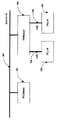
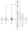
図1は、本実施形態に係る情報処理装置及び周辺装置からなる周辺装置制御システムをネットワーク環境下で実現した時のシステムの構成例を表すブロック図である。<Configuration example of peripheral device control system of this embodiment>
FIG. 1 is a block diagram illustrating a configuration example of a system when a peripheral device control system including an information processing device and a peripheral device according to the present embodiment is realized in a network environment.
図1において、702,703は情報処理装置であり、一般的なPCで構成される。PC702,703は、図3で後述するようなハードウェアで構成され、OS(Operating System)として、例えば米国マイクロソフト社のWindows(登録商標)XPがインストールされている。無論OSの種類はこれに限定されず、例えばLinux等でも適用可能であるが、以下では、米国マイクロソフト者のWindows(登録商標)を例に説明を行う。PC702とPC703は、Ethernet(登録商標)で構成されるネットワーク701を介して接続され、互いに双方向通信が可能である。本実施形態の周辺装置制御システムでは、PC703がサーバとなり、PC702がクライアントとなるような関係を持っている。すなわち、PC703は、プリンタ705、707を共有プリンタとしてネットワーク701を介して他の情報処理装置から印刷することができるようなプリントサーバの機能を備えている。 In FIG. 1,
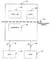
図2Aは、本実施形態に係る情報処理装置及び周辺装置からなる周辺装置制御システム部分の構成例を示すブロック図である。図2Aにおいて、図1の対応する要素には同じ参照番号が付与されている。 FIG. 2A is a block diagram illustrating a configuration example of a peripheral device control system portion including the information processing device and the peripheral device according to the present embodiment. In FIG. 2A, the same reference numerals are given to corresponding elements in FIG.
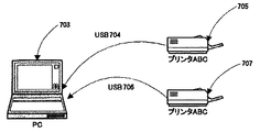
図2Aにおいて、PC703は図3で後述するようなハードウェアで構成され、OSとして米国マイクロソフト社のWindows(登録商標)XPがインストールされている。705,707はプリンタであり、カラーインクジェットプリンタで構成され、本実施形態における周辺装置である。本発明における周辺装置としては、プリンタ、複写機、ファクシミリ、またはこれらの複合機などの画像形成装置、スキャナ、デジタルカメラであってもよい。プリンタ705,706は、図4で後述するようなハードウェアで構成され、PC703とUSBインタフェース704,706を介して接続されており、互いに双方向通信が可能である。USBとはUniversal Serial Busの略であり、双方向通信が可能な公知のインタフェースである。なお、以下では情報処理装置601の通信インタフェースとして、USBインタフェースを例に説明を行うが、これに限定されない。例えば、無線通信に適用しても良いし、セントロニクスインタフェース、イーサーネットケーブルを介したLANインタフェース等を適用しても良い。 In FIG. 2A, a PC 703 is configured by hardware as will be described later with reference to FIG. 3, and Windows (registered trademark) XP of Microsoft Corporation is installed as an OS.
605は、Language Monitor(以下、LMとも示す)であり、Windows(登録商標)用のダイナミックリンクライブラリで構成される。ここで、LMについて詳しく説明する。LMは以下の2つの機能を備えたモジュールである。1つ目にステータス管理手段として機能する。具体的には、プリンタと双方向通信を行い、プリンタのステータスを取得し所定の場所に格納・保持させる。取得及び格納されたプリンタのステータスはSpoolerを経由して他のソフトウェアからアクセス可能となっている。2つ目に、プリンタに印刷ジョブのデータを含む各種データを送信する機能を備え、送信すべきデータにプリンタの制御コマンドなどを付加する機能等も有する。602は、アプリケーションである。アプリケーション602の一例としては、プリンタ705,707の状態を表示するステータスモニタ等が挙げられる。以下、本例では、このステータスモニタを中心に説明する。
603はレジストリであり、特定の記憶領域が割当てられており、OSの一部として管理される。アプリケーション602やLM605は、レジストリ603に任意の情報を格納したり参照することができる。特に本実施形態では、このレジストリにプリンタの各種ステータスが保持される。 A
604はPrinting and Print Spooler Interfacesである。アプリケーション602はPrinting and Print Spooler Interfaces604を利用して、LM605に情報を送ったり、LM605から情報を受け取ったりすることができる。 Reference numeral 604 denotes a printing and print spooler interfaces. The
図2Bは、本実施形態でのプリンタ・プール機能の概要を示す図である。 FIG. 2B is a diagram showing an overview of the printer pool function in the present embodiment.
プリンタ・プール機能とは、PCに接続された複数のプリンタを1つのキューで管理する技術である。図2Bでは、PC703に2台のプリンタ707,707が接続されていているが、これらの2台のプリンタは、1つのキューで管理される。 The printer pool function is a technique for managing a plurality of printers connected to a PC with one queue. In FIG. 2B, two
(PCのハードウエア構成例)
図3は、PCのハードウェア構成例を示すブロック図である。(PC hardware configuration example)
FIG. 3 is a block diagram illustrating a hardware configuration example of the PC.
図3において、PC702,703は、演算制御用の制御部であるCPU804により制御される。CPU804は、ランダムアクセスメモリ部(RAM801)を一時記憶部として使用し、記憶部であるハードディスクドライブ部(HDD802)からRAM801にロードされたプログラムにしたがってPCを制御する。入力部の一例であるキーボード部(KBD803)はデータ入力あるいは動作指示に使用され、表示部の一例である表示用ディスプレイ(LCD806)はデータ表示や状態報知に使用される。通信制御部の一例であるネットワークボード(NB805)は、ネットワーク701を介する通信を行なう。インタフェース部(I/F部808)は、周辺機器(本例ではプリンタ)との接続を制御する。バス807が、以上のPCの構成要素を互いに接続する。 In FIG. 3,
尚、上記RAM801には、以下の第1実施形態で示すスプーラやLMがアクセスするポート情報管理用構造体やポート情報構造体記憶部、ステータスモニタがスプーラを介してLMとやり取りするスキーマの記憶領域が確保される。又、第2実施形態で示すレジストリの記憶領域も確保される。更に、以下で示すエクスポート関数の引数や、各フローで種畜されたポート名、LMがプリンタから取得したステータスなどが一時記憶される領域も確保される。又、記憶部802は、可搬性CD−ROMまたは内部据付のROM、メモリカードなどであってもよく、プリントする画像データなどの大容量のデータや本実施形態で使用されるプログラムが記憶される。 The
(プリンタのハードウエア構成例)
図4は、プリンタのハードウェア構成例を示すブロック図である。(Example of printer hardware configuration)
FIG. 4 is a block diagram illustrating a hardware configuration example of the printer.
図4において、プリンタ705,707は、インタフェース部(I/F部)902と、RAM903と、ROM904と、CPU905と、エンジン906とを有する。 In FIG. 4,
そして、I/F部902は、コンピュータ(PC)のUSBインタフェース(I/F部808)に接続してある。インタフェース部902は、無線通信及び有線通信の双方の何れに適用しても良い。又、インタフェース部902は、セントロニクスインタフェースなどのホストとプリンタとが1対1で接続される形態や、ホストやプリンタとがイーサーネットケーブルを介してLAN接続される形態にも適用できる。 The I /
ROM904は制御プログラム等がストアしてある。CPU905は、ROM904にストアしてある制御プログラムに従ってプリンタ901の各部を制御するものである。又、RAM903は、CPU905の主メモリとワークメモリとして用いら、受信したデータを一旦保存するための受信バッファを有する。エンジン906は、RAM903に保存されたデータに基づきプリントを行うものである。尚、大容量の画像データを保持するためのHDDなどを有してもよい。本実施形態における周辺装置のエンジン906としてはインクジェット方式を例に説明を行うが、これに限定されることなく、例えば、電子写真方式、熱転写方式等のエンジン(媒体への記録手段)等を適用することもできる。 The
<本実施形態の周辺装置制御システムの動作例>
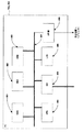
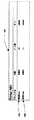
図5は、本実施形態に係る情報処理装置及び周辺装置からなる周辺装置制御システムのソフトウェア機能例を示すブロック図である。尚、本実施形態では、プリンタのプログラムは主要な要素でないので示さないが、本実施形態に係る処理としては、LMからのポーリングに対するステータスの返送や、プリント終了時のステータス返送などが関連する動作である。<Operation example of peripheral device control system of this embodiment>
FIG. 5 is a block diagram illustrating a software function example of the peripheral device control system including the information processing apparatus and the peripheral device according to the present embodiment. In this embodiment, the printer program is not shown because it is not a main element. However, as processing according to this embodiment, operations related to status return in response to polling from the LM, status return at the end of printing, and the like are related. It is.
図5において、001はPC703のソフトウエア構成例である。ここでは、本実施形態に関連のあるソフトウエアのみを示す。OS(Operating System)として米国マイクロソフト社のWindows(登録商標)XPがインストールされている。 In FIG. 5, 001 is a software configuration example of the
002,003は、周辺装置の状態をモニタするステータスモニタなどのアプリケーションである。ステータスモニタ002は、プリンタ705の状態をLM等の各種もモジュールを介してモニタ(監視)する。ステータスモニタ003はLM等の各種もモジュールを介してプリンタ707の状態をモニタ(監視)する。004は、OSやアプリケーションの情報を格納するレジストリである。これはWindows(登録商標)XPの枠組みで提供される機能であり、このレジストリ中に複数のキュー及び各キューに関連付けられたポートの情報が書き込まれている(後述の図14を参照)。005,006は、Printing and Print Spooler InterfacesでこれもWindows(登録商標)XPの枠組みで提供される機能である。007は、Spoolerで、Windows(登録商標)XPOSの一部であり、キュー008を管理する。008は、キューで、印刷ジョブをキューイングする。ここでキューについて少し詳しく説明する。キューとは、文書作成ソフトウェア等のアプリケーションデータに基づく印刷データを管理するモジュールである。キューにはプリンタ(ポート)を複数割り当てることができる。また、文書作成ソフトウェア等のアプリケーションから印刷指示を行うと、PCのハードディスク上の特定の場所に印刷データのファイルが作成され、キューはそのファイルを読み取り、印刷データの一覧を作成し表示する。更に、キューは印刷データを順番にプリンタに送信し印刷を行う。また、キューは印刷データの操作(一時停止、削除など)を行うことも可能となっている。 002 and 003 are applications such as a status monitor for monitoring the state of the peripheral device. The status monitor 002 monitors (monitors) the status of the
009,010,011は、LMで、データの通信I/Fとしてデータの送受信を制御する。LM009,010,011は、モジュールとしてはこの内、LM009とLM010は、キュー008からの印刷ジョブをプリンタに送信するときにSpooler007から呼ばれる。印刷ジョブがプリンタ705に送られるときはLM009が呼ばれる。印刷ジョブがプリンタ707に送られるときはLM010が呼ばれる。ステータスモニタ002,003がPrinting and Print Spooler Interfaces005,006を使ってLMと通信する場合は、LM011が呼ばれる。尚、図5では上記LM009,010,011を独立して記載しているが、これらは同じLMとして実行されてもよい。 Reference numerals 009, 010, and 011 denote LMs that control data transmission / reception as data communication I / Fs. LM009, 010, and 011 are modules, and LM009 and LM010 are called from Spooler007 when transmitting a print job from the queue 008 to the printer. When a print job is sent to the
012,013は、ポートモニタであり、LM009,010から送られてくるデータをUSBポートに対して送信したり、プリンタ705,707から送られてくるデータを受信したりする。ポートモニタとは、キューもしくはLMから受け取った印刷データをポートに書き込んだり、ポートに接続されたプリンタからプリンタの状態を読み込んだりするモジュールである。ポートへの書き込み、読み込みを行う際にはI/F毎に決められた手順があり、ポートモニタは手順に従い書き込み、読み込みを行う。ポートとは、USBなどのインタフェース毎に作成され、データを書き込み、読み込みを行う際の場所を示すものである。
704,706は、上述のUniversal Serial Bus(以降USB)であり、双方向通信が可能な公知のインタフェースである。ポート番号として、USB704にはUSB001が、USB707にはUSB002が割り当てられている。705,707は、上述のカラーインクジェットプリンタで本実施形態における周辺装置である。
上述のように、PC703にはプリンタ705とプリンタ707が接続されている。キュー008は、プリンタ・プール機能がONになっていて、プリンタ705とプリンタ707とが割り当てられている。 As described above, the
ステータスモニタ002は、レジストリ004を使ってLM009と通信し、Printing and Print Spooler Interface005を使ってLM011と通信して、プリンタ705の状態をモニタする。ステータスモニタ003は、レジストリ004を使ってLM010と通信し、Printing and Print Spooler Interfaces006を使ってLM011と通信して、プリンタ707の状態をモニタする。ここで、LM011はPrinting and Print Spooler Interfaces005,006を使ったプリンタの状態の問合わせに対する返信を行なうために起動される。プリンタ705,707の状態をモニタして、ステータス情報をレジストリ004やスプーラ007(LM011)が管理する後述のポート情報構造体に設定するのは、てLM009と010である。 The status monitor 002 communicates with the LM 009 using the
図6は、ステータスモニタがLMとの通信方式を決定する処理例を示すフローチャートである。より具体的には、ステータス問合手段として機能するステータスモニタが、LM(ステータス管理手段)への問合せと、レジストリ(予め準備された記憶領域)にポート単位で書き込まれたステータスの取得とを、予め定められた条件で切り替える処理を示す。レジストリ(予め準備された記憶領域)にポート単位でのステータスを記録する処理については、第2実施形態にて詳しく説明する。 FIG. 6 is a flowchart illustrating a processing example in which the status monitor determines the communication method with the LM. More specifically, the status monitor functioning as the status inquiry unit performs an inquiry to the LM (status management unit) and acquisition of the status written in the registry (a storage area prepared in advance) in units of ports. The process which switches on conditions defined beforehand is shown. Processing for recording the status in units of ports in the registry (a storage area prepared in advance) will be described in detail in the second embodiment.
ステータスモニタは、通信方式の決定処理を開始(S601)し、まず発行先がPC702か703かを判断し、現在の印刷がローカル印刷かどうかを判定する(S602)。例えば印刷要求に含まれるポート名にPC703の名称が含まれていれば、PC702で稼動するステータスモニタは、図6のS602でNoと判断する。ローカル印刷とは、図5で示したような印刷ジョブを発行するPCとプリンタが接続されているPCが同一である印刷のことである。例えば図1を例に説明すると、PC703が印刷ジョブの発行元の場合はローカル印刷となす。また、PC702が印刷ジョブの発行元の場合はPC703を経由して何れかのプリンタを利用するのでリモート印刷(ローカル印刷でない)と判断する。このリモート印刷のことを共有プリンタを用いた印刷と呼ぶこともある。 The status monitor starts communication type determination processing (S601), first determines whether the issue destination is
現在の印刷がローカル印刷の場合は、LMとの通信にはレジストリ004を使用する(S605)。S605の処理は後述する第2実施形態で詳しく説明する。一方、現在の印刷がローカル印刷でない場合は、現在のクライアントPC702、サーバPC703上のOSがレジストリ通信を行っても問題がないOSかどうかを判定する(S603)。この問題があるか否かの判定は、例えば印刷システムが稼動するOSの種類等により行われる。問題がない場合は、LMとの通信にはレジストリ004を使用する(S605)。問題がある場合は、LMとの通信にはPrinting and Print Spooler Interface005,006を使用する(S604)。このPrinting and Print Spooler Interface005,006は同一PC内、異なるPC間に係わらず使用できる。 If the current printing is local printing, the
かかるS604又はS604の経路によりプリンタ単位のステータスを確実に取得し、オペレータに対して表示して知らせる(S606)。なお、上の図6の説明では、S603の処理を行うよう説明したが、必要がなければ、適宜S603の処理は省略するようにしても良い。また、図6の説明では、LM(ステータス管理手段)への問合せと、レジストリ(予め準備された記憶領域)にポート単位で書き込まれたステータスの取得とを、切り替える条件として、S602、S603を例に説明したが、これに限定されない。例えば、他の予め定められた条件を適用するようにしても良い。 The status of each printer is reliably acquired through the route of S604 or S604, and is displayed and notified to the operator (S606). In the description of FIG. 6 above, the process of S603 has been described. However, if not necessary, the process of S603 may be appropriately omitted. In the description of FIG. 6, S602 and S603 are examples of conditions for switching between an inquiry to the LM (status management unit) and acquisition of the status written in the registry (a storage area prepared in advance) in units of ports. However, the present invention is not limited to this. For example, other predetermined conditions may be applied.
図7は、プリンタ・プール機能をONにして印刷を行った場合のキューの状態を示した図である。後述の図13のフローチャートの処理によりステータスモニタにより表示されるユーザインタフェースを示す。 FIG. 7 is a diagram illustrating a queue state when printing is performed with the printer pool function turned ON. 14 shows a user interface displayed by a status monitor by the processing of the flowchart of FIG.
1つのキュー101の名前は”Printer ABC”であり、プリンタ705とプリンタ707とが割り当てられている。1つ目のジョブ102はUSB001(704)に接続されたプリンタ705に送信されている。2つ目のジョブ103はUSB002(706)に接続されたプリンタ707に送信されている。このようにプリンタ・プール機能をONにして印刷を行った場合、一度に複数の印刷ジョブを処理することができる。 The name of one
<第1実施形態のステータスモニタ処理の動作例>
第1実施形態では、図6のS604の処理によって、LMとの通信にPrinting and Print Spooler Interfacesが選択された場合を想定している。尚、第1実施形態は、図5で説明したソフトウエアで構成されるが、ステータスモニタとLMの通信はPrinting and Print Spooler Interfaces005,006を用いて実施されるものとする。<Operation Example of Status Monitor Processing of First Embodiment>
In the first embodiment, it is assumed that “Printing and Print Spooler Interfaces” is selected for communication with the LM by the processing of S604 in FIG. The first embodiment is configured by the software described with reference to FIG. 5. However, the communication between the status monitor and the LM is performed using the Printing and Print Spooler Interfaces 005 and 006.
(ポート情報の管理構成例)
図8は、Spooler007とLMがポート情報をどのように管理しているかの例を示す図であり、ポート毎のステータスを保持する保持部を示す。尚、以下のポート情報はSpooler007が管理し、ポート情報の作成及び書込みはLM009,010が行ない、ポート情報のステータスモニタからの問合わせへの返信はLM011が行なう。なお、図8の格納場所は、LMが独自に作成した格納場所でも良いし、OSが提供する予め定められた格納場所でも良いし、LM及びOSが共有する格納場所でも良い。(Port information management configuration example)
FIG. 8 is a diagram illustrating an example of how the Pooler 007 and the LM manage port information, and shows a holding unit that holds a status for each port. The following port information is managed by Spooler 007, port information is created and written by LM009,010, and LM011 sends a reply to the inquiry from the status monitor of the port information. Note that the storage location in FIG. 8 may be a storage location uniquely created by the LM, a predetermined storage location provided by the OS, or a storage location shared by the LM and the OS.
202と203は、ポート情報構造体で、プリンタが接続されている各ポートの情報を格納し、Spooler007がLM090及び010のエクスポート関数であるOpenPortEx()を呼ぶ毎に、各LMにより接続ポート毎に作成される。すなわち、PC703が起動して各ポートに対応するLM009,010が起動された後、各LM009,010に対してSpooler007からポート初期化に相当するOpenPortEx()を呼んだ時に、各ポート情報構造体が作成される。図5における、LM009,010が、ポートに接続されたプリンタから取得した紙無しエラーなどのステータス情報もポート情報構造体に格納される。また、後述の図11で説明するポート名等のポート識別子もこのポート情報に含まれる。これら、LM009,010の各々がプリンタ705、707からステータス情報を取得し、更新することによって、上に説明した図8のポート毎のステータス情報が更新される。 202 and 203 are port information structures that store information of each port to which the printer is connected, and each time the Spooler 007 calls OpenPortEx (), which is an export function of LM090 and 010, for each connection port. Created. That is, after the
上記ポート情報構造体の管理は、ポート情報管理用構造体201を用いて行われる。ポート情報管理用構造体201は、Spooler007がLMのエクスポート関数であるInitializePrintMonitor2()を呼んだときに、LMによって作成される。すなわち、PC703が起動して各ポートに対応するLM009,010が起動された後、Spooler007がLM009,010いずれかのInitializePrintMonitor2()を呼んだときに、ポート情報管理用構造体201が作成される。 The port information structure is managed using the port
ポート情報管理用構造体のメンバ変数のpFirstPortには1番目のポート情報構造体202(ここではUSB002ポートのポート情報構造体)へのポインタが格納されている。1番目のポート情報構造体のメンバ変数pNextは2番目のポート情報構造体203(ここではUSB001ポートのポート情報構造体)へのポインタが格納されている。ポート情報構造体にはポート情報管理用構造体のアドレスも格納されており、ポート情報構造体からポート情報管理用構造体を特定することにより全てのポートのポート情報構造体を参照することが可能になっている。尚、OpenPortEx()、InitializePrintMonitor2()は、上記MSDNで公開されている既知の情報である。 A pointer to the first port information structure 202 (here, the port information structure of the USB002 port) is stored in the member variable pFirstPort of the port information management structure. The member variable pNext of the first port information structure stores a pointer to the second port information structure 203 (here, the port information structure of the USB001 port). The address of the port information management structure is also stored in the port information structure, and it is possible to refer to the port information structure of all ports by specifying the port information management structure from the port information structure It has become. Note that OpenPortEx () and InitializePrintMonitor2 () are known information published on the MSDN.
以下、上記ポート情報管理用構造体及びポート情報構造体の作成手順例を示す。 Hereinafter, an example of a procedure for creating the port information management structure and the port information structure will be described.
(ポート情報管理用構造体の作成手順例)
図9は、LM009又は010がエクスポート関数InitializePrintMonitor2()でポート情報管理用構造体201を作成する処理例を示すフローチャートである。(Example of procedure for creating port information management structure)
FIG. 9 is a flowchart illustrating a processing example in which the LM009 or 010 creates the port
Spooler007がOSやアプリケーションからプリントモニタの初期化を指示されて、LM009又は010のエクスポート関数であるInitializePrintMonitor2()をコールする(S701)する。LM009又は010がInitializePrintMonitor2()の処理を開始する(S702)。LMは、ポート情報管理用構造体201を作成する(S703)。作成したポート情報管理用構造体201をInitializePrintMonitor2()の第2引数のphMonitorにセットする。それを、monitor handleとしてSpooler007に返却し、LMの処理を終了する(S704)。 Spooler 007 is instructed by the OS or application to initialize the print monitor, and calls InitializePrintMonitor2 (), which is an export function of LM009 or 010 (S701). The LM009 or 010 starts the process of InitializePrintMonitor2 () (S702). The LM creates the port information management structure 201 (S703). The created port
Spooler007はInitializePrintMonitor2()の第2引数を通して、monitor handleとしてポート情報管理用構造体201を受け取る。そして、InitializePrintMonitor2()のコールを終了する(S705)。 Spooler 007 receives the port
(ポート情報構造体の作成手順例)
図10は、LM090又は010がエクスポート関数OpenPortEx()でポート情報構造体202又は203を作成する処理を表すフローチャートである。(Example of port information structure creation procedure)
FIG. 10 is a flowchart showing processing in which the LM 090 or 010 creates the
Spooler007がOSやアプリケーションからポートの初期化を指示されて、、ポートに対応するLM090又は010のエクスポート関数であるOpenPortEx()をコールする(S801)。LM090又は010がOpenPortEx()の処理を開始する(S802)。LMはOpenPortEx()の第2引数として渡されるポート情報管理用構造体201を取得する(S803)。このポート情報管理用構造体201は、図9のS703で作成したものである。LMは、ポート情報構造体202又は203を作成(S804)する。 Spooler 007 is instructed by the OS or application to initialize the port, and calls OpenPortEx (), which is an export function of LM090 or 010 corresponding to the port (S801). The LM090 or 010 starts the OpenPortEx () process (S802). The LM acquires the port
次に、作成したポート情報構造体をリンクする。例えば図8のようにポート情報構造体203が既に作成されている場合に、ポート情報構造体202を作成する場合を示す。この場合は、LM009が、S804で新たに作成されたポート情報構造体202のメンバ変数pNextに、ポート情報管理用構造体201のメンバ変数pFirstPortで指定されているポート情報構造体203のアドレスを格納する(S805)。さらに、ポート情報管理用構造体201のメンバ変数pFirstPortに、S804で新たに作成されたポート情報構造体202のアドレスを格納する(S806)。ポート情報構造体202のメンバ変数にポート情報管理用構造体201のアドレスを格納する(S807)。ポート情報構造体202をOpenPortEx()の第5引数pHandleにセットして、port handleとしてSpooler007に返却し、LMの処理を終了する(S808)。Spooler007はOpenPortEx()の第5引数を通して、port handleとしてポート情報構造体を受け取りOpenPortEx()のコールを終了する(S809)。 Next, the created port information structure is linked. For example, FIG. 8 shows a case where the
(プリンタのステータス情報の通信構成例)
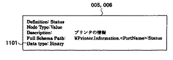
図11は、ステータスモニタとLM011がPrinting and Print Spooler Interfaces005,006を用いてプリンタのステータス情報に関する通信を行うときに使われるスキーマである。スキーマはXML等のマークアップ言語で記述されている。スキーマは、ステータスモニタとLM011が通信を行う際にステータスモニタによって作成される。ここで、スキーマとは一般的には、データベース全体の構造のことまたは、それらを記述したファイルを意味するが、ここでは周辺装置の状態を表現する表現方法・形式のこと意味するものとする。(Example communication configuration of printer status information)
FIG. 11 is a schema used when the status monitor and the LM 011 communicate with each other regarding the printer status information using the Printing and Print Spooler Interfaces 005 and 006. The schema is described in a markup language such as XML. The schema is created by the status monitor when the status monitor and the LM011 communicate with each other. Here, the schema generally means the structure of the entire database or a file describing them, but here it means an expression method / format for expressing the state of the peripheral device.
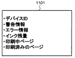
定義名はStatus、NodeTypeはValue、スキーマのフルパスは、¥Printer.Information.<PortName>:Status、Data typeはBinary形式、である。<PortName>には、プリンタが接続されているポート識別子が入る。実施例1ではポート識別子として、ポート名を用いる。例えば、USB001に接続されたプリンタのステータス情報を取得する場合は、スキーマのフルパスは、¥Printer.Information.USB001:Statusとなる。プリンタのステータス情報1101はBinary形式で格納される。 The definition name is Status, NodeType is Value, and the full path of the schema is \ Printer. Information. <PortName>: Status and Data type are in binary format. <PortName> contains a port identifier to which the printer is connected. In the first embodiment, a port name is used as a port identifier. For example, when acquiring the status information of a printer connected to USB001, the full path of the schema is \ Printer. Information. USB001: Status. The
図12は、Binary形式で格納されるプリンタのステータス情報1101の一例である。 FIG. 12 shows an example of
図12の例では、プリンタのデバイスID、インクが少なくなっているなどの警告情報、紙無しエラーなどのエラー情報、インク残量、印刷中のページ情報、印刷済みのページ情報、などが格納されているが、これに限定されない。 In the example of FIG. 12, the device ID of the printer, warning information such as low ink, error information such as a paper out error, the remaining amount of ink, page information being printed, printed page information, and the like are stored. However, it is not limited to this.
(プリンタのステータス情報の通信手順例)
図13は、ステータスモニタがPrinting and Print Spooler Interfacesを用いてプリンタのステータス情報を取得する処理を表すフローチャートである。(Example of communication procedure for printer status information)
FIG. 13 is a flowchart illustrating a process in which the status monitor acquires printer status information using Printing and Print Spooler Interfaces.
図13で、ステータスモニタは、印刷ジョブやオペレータからの問い合せなどのアプリケーションやOSの要求に従って、プリンタステータスの取得処理を開始する(S301)。1つのキューに複数の周辺装置(ポート)が割り当てられた場合、つまりプリンタ・プールが実行されている場合に印刷ジョブやオペレータからの問い合せなどに基づいてプリンタのポート名を取得する(S302)。一方、プリンタ・プールが指定されていない場合にはS302でポートの取得は行わず、LMに対してポート識別子を含まないスキーマを発行する。この場合にはS307でNOと判定される。取得したポート名を元に、Printing and Print Spooler Interfaces005,006で使うスキーマのパスを作成(S303)する。作成したスキーマを引数にPrinting and Print Spooler Interfacesの関数−IBidiSpl::SendRecv()をコールする(S303)。該SendRecv()のコールに基づき、Spooler007からLM011のエクスポート関数SendRecvBidiDataFromPort()が呼ばれる(S305)。 In FIG. 13, the status monitor starts printer status acquisition processing in accordance with an application or OS request such as a print job or an inquiry from an operator (S301). When a plurality of peripheral devices (ports) are assigned to one queue, that is, when a printer pool is being executed, a printer port name is acquired based on an inquiry from a print job or an operator (S302). On the other hand, if the printer pool is not specified, the port is not acquired in S302, and a schema not including the port identifier is issued to the LM. In this case, NO is determined in S307. Based on the acquired port name, a schema path to be used in Printing and Print Spooler Interfaces 005, 006 is created (S303). Using the created schema as an argument, the function “IBidiSpl :: SendRecv ()” of “Printing and Print Spooler Interfaces” is called (S303). Based on the call to SendRecv (), the export function SendRecvBidiDataFromPort () of Spooler007 to LM011 is called (S305).
Spooler007からはSendRecvBidiDataFromPort()の引数として、ステータスモニタがS303で作成したポートに対応するスキーマ及びポート情報構造体が、LM011に渡される。ポート情報構造体は、Spooler007がLM090又は010のエクスポート関数OpenPort()をコールした際、LM090又は010が作成したものである。 From Spooler007, the schema and port information structure corresponding to the port created by the status monitor in S303 are passed to LM011 as arguments of SendRecvBidiDataFromPort (). The port information structure is created by LM090 or 010 when Spooler007 calls the export function OpenPort () of LM090 or 010.
キュー008にはポートが2つ割り当てられている(USB001とUSB002)が、渡されるポート情報構造体は1つだけである。ステータスモニタがスキーマにポート識別子を指定している場合は、指定されたポート情報構造体が渡されるが、指定がなければどちらのポートのポート情報構造体が渡されるかはSpoolerの仕様に依存する。 Two ports are assigned to the queue 008 (USB001 and USB002), but only one port information structure is passed. If the status monitor specifies a port identifier in the schema, the specified port information structure is passed. If not specified, which port's port information structure is passed depends on the specification of the Spooler. .
SendRecvBidiDataFromPort()で引数として渡されたスキーマを取得し(S306)、スキーマにポート識別子が含まれているかどうかを確認する(S307)。ポート識別子が含まれている場合は、図8で説明した方法で管理されているポート情報構造体からポート識別子と一致するポート情報構造体を取得する(S308)。より具体的には、図8のポート情報に含まれるポート識別子と、図11のスキーマに含まれるポート識別子(<PortName>)と、の一致により、参照すべきポート情報を特定する。該特定されたポート情報中に保持されるステータスを読込み、ステータス要求元に返信する。 The schema passed as an argument by SendRecvBidiDataFromPort () is acquired (S306), and it is confirmed whether or not the port identifier is included in the schema (S307). If the port identifier is included, a port information structure that matches the port identifier is acquired from the port information structure managed by the method described with reference to FIG. 8 (S308). More specifically, the port information to be referred to is specified by matching the port identifier included in the port information of FIG. 8 with the port identifier (<PortName>) included in the schema of FIG. The status held in the specified port information is read and returned to the status request source.
ポート情報構造体の取得に成功した場合は(S309)、S311に進む。
ポート識別子が含まれていない場合は(S309)、Spooler007から渡されたポート情報構造体(従来から知られている予め決められたポートのステータス)を使い(S310)、S311に進む。If acquisition of the port information structure is successful (S309), the process proceeds to S311.
If the port identifier is not included (S309), the port information structure (predetermined port status conventionally known) passed from Spooler007 is used (S310), and the process proceeds to S311.
選別されたポート情報構造体に保存されているプリンタのステータスを取得し(S311)、取得したステータスをスキーマの定義に変換する(S312)。SendRecvBidiDataFromPort()関数の引数としてスキーマの定義に変換されたプリンタのステータスをSpooler007を介してステータスモニタに返す。そして、SendRecvBidiDataFromPort()関数の処理を終了する(S313)。 The printer status stored in the selected port information structure is acquired (S311), and the acquired status is converted into a schema definition (S312). The printer status converted into the schema definition as an argument of the SendRecvBidiDataFromPort () function is returned to the status monitor via the Spooler007. Then, the process of the SendRecvBidiDataFromPort () function is terminated (S313).
ステータスモニタはステータスを取得し、必要であれば表示する(S314)。 The status monitor acquires the status and displays it if necessary (S314).
<第2実施形態のステータスモニタ処理の動作例>
第2実施形態も、図5で説明したソフトウエアで構成されが、ステータスモニタとLMの通信は、図6のS605の処理によってレジストリ004を経由する場合を想定している。<Operation Example of Status Monitor Processing of Second Embodiment>
The second embodiment is also configured by the software described with reference to FIG. 5, but it is assumed that the communication between the status monitor and the LM passes through the
ステータスモニタとLMとの通信にレジストリ004を使う理由は以下の理由である。Windows(登録商標)XP、2000などのOSではキュー毎にレジストリの特定の場所が割り当てられていて、そこにアクセスするGetPrinterDataEx()やSetPrinterDataEx()などのAPIも用意されている。いわば、レジストリの使用は、OSが推奨する通信方法の1つである。従って、以下のような利点がある。すなわち、この方法を使うことにより将来OSの仕様が変更された場合でも、推奨の通信方法を使っている場合は仕様の差異をOSが吸収してくれたり、他のモジュールやアプリケーションがAPIで容易にレジストリに書かれた情報を参照できる。 The reason why the
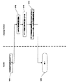
図14は、プリンタのステータスがレジストリ004のどの階層に記録されるかを示している。 FIG. 14 shows in which level of the
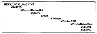
”HKEY_LOCAL_MACHINE¥SYSTEM¥CurrentControlSet¥Control¥Print¥Printers”の階層に、キュー毎に一意のキーが作成される。ここでは、キュー008用に”Printer ABC”というキーが作成されている。”Printer ABC”の下位の階層に、”PrinterDriverData”が作られ、その下位の層にポート毎に”USB001”、”USB002”というキーが作成されている。また、仮に別のキュー(例えば”Printer EDF”に対応のキュー)が存在すれば、図14中には、”Printer ABC”と並列に、”Printer EDF”に係わる情報が記録される。 A unique key is created for each queue in the hierarchy of “HKEY_LOCAL_MACHINE \ SYSTEM \ CurrentControlSet \ Control \ Print \ Printers". Here, a key “Printer ABC” is created for the queue 008. “PrinterDriverData” is created in the lower layer of “Printer ABC”, and keys “USB001” and “USB002” are created for each port in the lower layer. If another queue (for example, a queue corresponding to “Printer EDF”) exists, information relating to “Printer EDF” is recorded in parallel with “Printer ABC” in FIG.
LM009又は010は、プリンタのステータスをポート毎に記録する。USB001に接続されているプリンタ705のステータスは”USB001”の階層に記録する。USB002に接続されているプリンタ707のステータスは”USB002”の階層に記録する。 The LM009 or 010 records the printer status for each port. The status of the
図15は、レジストリ004に記録されるプリンタのステータス情報の一例である。 FIG. 15 is an example of printer status information recorded in the
値”Printer_Status_Cartridge”は、プリンタに搭載されているカートリッジ情報であり、値の種類は”REG_SZ型”という文字列であり、中身には”Color”という文字列が入っている。この情報から、プリンタにはColorカートリッジが搭載されていることがわかる。 The value “Printer_Status_Cartridge” is cartridge information mounted on the printer, the value type is a character string “REG_SZ type”, and the content contains a character string “Color”. From this information, it can be seen that the color cartridge is installed in the printer.
値”Printer_Status_Error”は、プリンタに発生しているエラー情報であり、値の種類は”REG_SZ型”という文字列であり、中身には”No”という文字列が入っている。この情報からプリンタにはエラーが発生していないことがわかる。 The value “Printer_Status_Error” is error information generated in the printer, the value type is a character string “REG_SZ type”, and the content contains a character string “No”. This information shows that no error has occurred in the printer.
値”Printer_Status_Warning”は、プリンタに発生している警告情報であり、値の種類は”REG_DWORD型”というDWORD値であり、中身は”500”となっている。この情報からプリンタには警告コード500という警告が発生していることがわかる。 The value “Printer_Status_Warning” is warning information generated in the printer, the type of the value is a DWORD value “REG_DWORD type”, and the content is “500”. From this information, it can be seen that a warning with a warning code 500 has occurred in the printer.
値”Printer_Status_Ink_Color”は、プリンタのColorインクの残量情報であり、値の種類は”REG_DWORD型”というDWORD値であり、中身は”70”となっている。この情報からプリンタのColorインクの残量は70であることがわかる。 The value “Printer_Status_Ink_Color” is the remaining amount information of the color ink of the printer, the type of the value is a DWORD value “REG_DWORD type”, and the content is “70”. From this information, it can be seen that the remaining amount of color ink in the printer is 70.
尚、プリンタのステータス情報は上記例に限定されない。 The printer status information is not limited to the above example.
(ステータスモニタのステータス取得手順例)
図16は、ステータスモニタがレジストリ004を用いてプリンタのステータスを取得する方法を示すフローチャートである。(Example of status monitor status acquisition procedure)
FIG. 16 is a flowchart illustrating a method in which the status monitor acquires the printer status using the
ステータスモニタが、印刷ジョブやオペレータからの問い合せなどのアプリケーションやOSの要求に従って、ステータスの取得を開始する(S401)。印刷ジョブやオペレータからの問い合せなどのアプリケーションから、ステータスを取得するプリンタのポート名を取得する(S402)。取得したポート名を元に、レジストリの階層を指定するパスを作成する。例えば、USB001に接続されているプリンタ705のステータスを取得する場合のパスは、以下のようになる。 The status monitor starts status acquisition in accordance with an application or OS request such as a print job or an inquiry from an operator (S401). The port name of the printer whose status is acquired is acquired from an application such as a print job or an inquiry from the operator (S402). Create a path that specifies the hierarchy of the registry based on the acquired port name. For example, the path for acquiring the status of the
”HKEY_LOCAL_MACHINE¥SYSTEM¥CurrentControlSet¥Control¥Print¥Printers¥Printer ABC¥PrinterDriverData¥USB001”
ステータスモニタは、作成したパスを指定してレジストリ004にアクセスし(S403)、プリンタのステータスを取得し(S404)、終了する(S405)。パスには、キューとポートとの指定が含まれている。“HKEY_LOCAL_MACHINE ¥ SYSTEM ¥ CurrentControlSet ¥ Control ¥ Print ¥ Printers ¥ Printer ABC ¥ PrinterDriverData ¥ USB001”
The status monitor specifies the created path, accesses the registry 004 (S403), acquires the printer status (S404), and ends (S405). The path includes a queue and port designation.
(レジストリへのステータス格納手順例)
図17は、LM009又は010がレジストリ004にプリンタのステータスを格納する方法を示すフローチャートである。(Example of status storage procedure in the registry)
FIG. 17 is a flowchart showing how the LM 009 or 010 stores the printer status in the
LM009又は010は、定期的な(例えば4秒に1回)ポーリングや印刷処理の終了などで処理を開始する(S501)。上記ポーリングやプリンタからのイベント情報により、レジストリ004にステータスを保存するプリンタのポート名を取得する(S502)。取得したポート名を元に、レジストリ004の階層を指定するパスを作成する。例えば、USB001に接続されているプリンタ016のステータスを保存する場合のパスは、以下のようになる。 The LM009 or 010 starts processing at regular (for example, once every 4 seconds) polling or the end of printing processing (S501). Based on the polling and event information from the printer, the printer port name whose status is stored in the
”HKEY_LOCAL_MACHINE¥SYSTEM¥CurrentControlSet¥Control¥Print¥Printers¥Printer ABC¥PrinterDriverData¥USB001”
作成したパスでレジストリ004にアクセスし(S503)、プリンタから取得したステータスを保存し(S504)、終了する(S505)。“HKEY_LOCAL_MACHINE ¥ SYSTEM ¥ CurrentControlSet ¥ Control ¥ Print ¥ Printers ¥ Printer ABC ¥ PrinterDriverData ¥ USB001”
The
<他の実施形態>
上記実施形態では、アプリケーションの一例としてステータスモニタ002,003を挙げたが、この例に限られることはない。例えば周辺装置から情報を取得して、表示を行う任意のアプリケーションで実現可能であり、本発明はその場合でも有効である。
又、上記実施形態では、情報処理装置としてパーソナルコンピュータを想定したが、この例に限られることはない。例えばDVDビデオプレーヤー、ゲーム、セットトップボックス、インターネット家電等、同様な使用方法が可能な任意の端末に対して実現することができ、本発明はその場合でも有効である。<Other embodiments>
In the above embodiment, the status monitors 002 and 003 are given as an example of the application. However, the application is not limited to this example. For example, the present invention can be realized by an arbitrary application that acquires information from a peripheral device and performs display, and the present invention is effective even in that case.
In the above embodiment, a personal computer is assumed as the information processing apparatus, but the present invention is not limited to this example. For example, the present invention can be realized for any terminal that can be used in a similar manner, such as a DVD video player, a game, a set-top box, and an Internet home appliance, and the present invention is effective even in that case.
又、上記実施形態では、周辺装置としてプリンタを例示しているが、周辺装置として他に、複写機、ファクシミリ、および印刷、スキャナ、ファックスの機能などを備える複合機などのいずれかが、本発明の適用対象となり得る。 In the above-described embodiment, a printer is exemplified as the peripheral device. However, any one of a copier, a facsimile, and a multifunction machine having functions of printing, a scanner, a fax, and the like may be used as the peripheral device. Can be applied.
又、上記実施形態では、OSに例としてWindows(登録商標)XP、2000を使用したが、これらのOSに限られることなく、任意のOSを使用することができる。 In the above embodiment, Windows (registered trademark) XP, 2000 is used as an example of the OS. However, the present invention is not limited to these OSs, and any OS can be used.
又、上記実施形態では、PC001とプリンタ016、プリンタ017との間のインタフェースとして、USBインタフェースを用いたが、このインタフェースに限られない。例えば、Ethernet(登録商標)、無線LAN、IEEE1394、Bluetooth、IrDA、パラレル、シリアル等の任意のインタフェースを用いるようにしてもよい。 In the above embodiment, the USB interface is used as an interface between the PC 001, the printer 016, and the printer 017. However, the present invention is not limited to this interface. For example, any interface such as Ethernet (registered trademark), wireless LAN, IEEE 1394, Bluetooth, IrDA, parallel, and serial may be used.
又、上記実施形態では、LMとポートモニタを分けて実装している形態を示したが、LMの機能をポートモニタに含めて実装しても実現可能であり、本発明はその場合でも有効である。 In the above embodiment, the LM and the port monitor are separately mounted. However, the LM function can be implemented by including it in the port monitor, and the present invention is effective even in that case. is there.
又、本発明の目的は、前述した実施形態の機能を実現するソフトウェアのプログラムコードを記録した記憶媒体を、システム或いは装置に供給する。そして、そのシステム或いは装置のコンピュータ(またはCPUやMPU)が記憶媒体に格納されたプログラムコードを読み出し実行することによっても、達成されることは言うまでもない。この場合、記憶媒体から読み出されたプログラムコード自体が前述した実施形態の機能を実現することになり、プログラムコード自体及びそのプログラムコードを記憶した記憶媒体は本発明を構成することになる。 Another object of the present invention is to supply a storage medium storing software program codes for realizing the functions of the above-described embodiments to a system or apparatus. Needless to say, this can also be achieved by the computer (or CPU or MPU) of the system or apparatus reading and executing the program code stored in the storage medium. In this case, the program code itself read from the storage medium realizes the functions of the above-described embodiments, and the program code itself and the storage medium storing the program code constitute the present invention.
プログラムコードを供給するための記憶媒体としては、例えば、フレキシブルディスク、ハードディスク、光ディスク、光磁気ディスク、CD−ROM、CD−R、磁気テープ、不揮発性のメモリカード、ROM等を用いることができる。 As a storage medium for supplying the program code, for example, a flexible disk, a hard disk, an optical disk, a magneto-optical disk, a CD-ROM, a CD-R, a magnetic tape, a nonvolatile memory card, a ROM, or the like can be used.
又、コンピュータが読み出したプログラムコードを実行することにより、前述した実施形態の機能が実現されるだけでない。そのプログラムコードの指示に基づき、コンピュータ上で稼動しているOSなどが実際の処理の一部又は全部を行い、その処理によって前述した第1の実施形態や第2の実施の形態の機能が実現される場合も含まれることは言うまでもない。 Further, the functions of the above-described embodiments are not only realized by executing the program code read by the computer. Based on the instruction of the program code, the OS running on the computer performs part or all of the actual processing, and the functions of the first embodiment and the second embodiment described above are realized by the processing. Needless to say, it is also included.
更に、記憶媒体から読み出されたプログラムコードが、コンピュータに挿入された機能拡張ボードやコンピュータに接続された機能拡張ユニットに備わるメモリに書込まれる。その後、そのプログラムコードの指示に基づき、その機能拡張ボードや機能拡張ユニットに備わるCPU等が実際の処理の一部又は全部を行い、その処理によって前述した実施形態の機能が実現される場合も含まれることは言うまでもない。 Further, the program code read from the storage medium is written in a memory provided in a function expansion board inserted into the computer or a function expansion unit connected to the computer. After that, based on the instruction of the program code, the CPU of the function expansion board or function expansion unit performs part or all of the actual processing, and the function of the above-described embodiment is realized by the processing. Needless to say.
以上説明したように、本実施形態によれば、キューに複数の周辺装置が割り当てられている場合においても、個々の周辺装置のステータスを正常に、管理して表示することができる。 As described above, according to this embodiment, even when a plurality of peripheral devices are assigned to the queue, the status of each peripheral device can be managed and displayed normally.
Claims (10)
周辺装置と通信を行い前記周辺装置のステータスを、前記1つのキューを単位に接続されたポート毎に取得して、オペレーティングシステムが管理するステータス保持部に保持するステータス管理手段と、
前記周辺装置を接続したポートを識別するポート識別子を含むスキーマを引数として、前記オペレーティングシステムが提供するインタフェースの所定の関数をコールすることにより、周辺装置のステータスを前記ステータス管理手段へ問い合わせるステータス問合手段と、
前記ステータス問合手段から発行されたステータスの問い合わせメッセージに含まれる前記スキーマのポート識別子を認識するポート識別子認識手段と、
前記ポート識別子認識手段が認識したポート識別子に対応するポートに接続された周辺装置のステータスを、前記ステータス保持部から読み出して前記ステータス問合手段に返信するステータス返信手段と
を有することを特徴とする情報処理装置。 An information processing apparatus capable of assigning a plurality of peripheral devices to one queue for managing peripheral devices,
Status management means that communicates with a peripheral device, acquires the status of the peripheral device for each port connected in units of the one queue, and holds it in a status holding unit managed by an operating system ;
A status query that inquires the status management means of the status of the peripheral device by calling a predetermined function of the interface provided by the operating system with a schema including a port identifier for identifying the port connected to the peripheral device as an argument Means,
Port identifier recognition means for recognizing the port identifier of the schema included in the status inquiry message issued from the status inquiry means;
And a status reply unit that reads the status of the peripheral device connected to the port corresponding to the port identifier recognized by the port identifier recognition unit from the status holding unit and returns the status to the status inquiry unit. Information processing device.
前記ステータス返信手段は、前記ポート識別子判定手段にてポート識別子が含まれてないと判定した場合に、予め決められたポートのステータスを返信することを特徴とする請求項1に記載の情報処理装置。 Port identifier determination means for determining whether or not the port identifier is included in the schema included in the status inquiry message issued from the status inquiry means;
2. The information processing apparatus according to claim 1, wherein the status reply unit returns a status of a predetermined port when the port identifier determination unit determines that the port identifier is not included. .
前記ステータス問合手段は、前記ステータス管理手段への問合せと、前記記憶領域にポート単位で書き込まれたステータスの取得とを、予め定められた条件で切り替えることを特徴とする請求項1又は2に記載の情報処理装置。 The status management means records the status of the peripheral device in a storage area prepared in advance for each port,
3. The status inquiry unit switches between an inquiry to the status management unit and acquisition of a status written in the storage area in units of ports according to a predetermined condition. The information processing apparatus described.
周辺装置と通信を行い前記周辺装置のステータスを、前記1つのキューを単位に接続されたポート毎に取得して、オペレーティングシステムが管理するステータス保持部に保持するステータス管理工程と、
前記周辺装置を接続したポートを識別するポート識別子を含むスキーマを引数として、前記オペレーティングシステムが提供するインタフェースの所定の関数をコールすることにより、周辺装置のステータスを前記ステータス管理工程で管理しているステータスに対して問い合わせるステータス問合工程と、
前記ステータス問合工程で発行されたステータスの問い合わせメッセージに含まれる前記スキーマのポート識別子を認識するポート識別子認識工程と、
前記ポート識別子認識工程で認識したポート識別子に対応するポートに接続された周辺装置のステータスを、前記ステータス保持部から読み出して返信するステータス返信工程と
を有することを特徴とする周辺装置制御方法。 A peripheral device control method for an information processing apparatus capable of assigning a plurality of peripheral devices to one queue for managing peripheral devices,
A status management step of communicating with a peripheral device, acquiring the status of the peripheral device for each port connected in units of the one queue, and holding it in a status holding unit managed by an operating system ;
The status management process manages the status of the peripheral device by calling a predetermined function of the interface provided by the operating system with a schema including a port identifier for identifying the port connected to the peripheral device as an argument . Status inquiry process for inquiring on status,
A port identifier recognition step for recognizing the port identifier of the schema included in the status inquiry message issued in the status inquiry step;
A peripheral device control method comprising: a status reply step of reading out the status of the peripheral device connected to the port corresponding to the port identifier recognized in the port identifier recognition step from the status holding unit and returning the status.
前記ステータス返信工程では、前記ポート識別子判定工程でポート識別子が含まれてないと判定した場合に、予め決められたポートのステータスを返信することを特徴とする請求項5に記載の周辺装置制御方法。 A port identifier determination step for determining whether or not the port identifier is included in the schema included in the status inquiry message issued in the status inquiry step;
6. The peripheral device control method according to claim 5 , wherein, in the status return step, a status of a predetermined port is returned when it is determined that the port identifier is not included in the port identifier determination step. .
前記ステータス問合工程では、前記ステータス管理工程で管理されているステータスへの問合せと、前記記憶領域にポート単位で書き込まれたステータスの取得とを、予め定められた条件で切り替えることを特徴とする請求項5又は6に記載の周辺装置制御方法。 In the status management step, the status of the peripheral device is recorded in units of ports in a storage area prepared in advance,
In the status inquiry step, the status inquiry managed in the status management step and the acquisition of the status written in the storage area in units of ports are switched according to a predetermined condition. The peripheral device control method according to claim 5 or 6 .
Priority Applications (5)
| Application Number | Priority Date | Filing Date | Title |
|---|---|---|---|
| JP2006077711A JP4667281B2 (en) | 2006-02-20 | 2006-02-20 | Peripheral device control method, information processing apparatus and control program therefor |
| US11/674,935 US7581050B2 (en) | 2006-02-20 | 2007-02-14 | Information processing apparatus, peripheral apparatus control method, and computer readable medium |
| EP07102540.7A EP1821192B1 (en) | 2006-02-20 | 2007-02-16 | Information processing apparatus, peripheral apparatus control method, and computer readable medium |
| KR1020070016990A KR100872955B1 (en) | 2006-02-20 | 2007-02-20 | Information processing apparatus, peripheral apparatus control method, and computer readable medium |
| CN2007100858455A CN101025679B (en) | 2006-02-20 | 2007-02-25 | Printing control system and method of information processing apparatus |
Applications Claiming Priority (1)
| Application Number | Priority Date | Filing Date | Title |
|---|---|---|---|
| JP2006077711A JP4667281B2 (en) | 2006-02-20 | 2006-02-20 | Peripheral device control method, information processing apparatus and control program therefor |
Publications (3)
| Publication Number | Publication Date |
|---|---|
| JP2007226755A JP2007226755A (en) | 2007-09-06 |
| JP2007226755A5 JP2007226755A5 (en) | 2009-01-22 |
| JP4667281B2 true JP4667281B2 (en) | 2011-04-06 |
Family
ID=38054651
Family Applications (1)
| Application Number | Title | Priority Date | Filing Date |
|---|---|---|---|
| JP2006077711A Expired - Fee Related JP4667281B2 (en) | 2006-02-20 | 2006-02-20 | Peripheral device control method, information processing apparatus and control program therefor |
Country Status (5)
| Country | Link |
|---|---|
| US (1) | US7581050B2 (en) |
| EP (1) | EP1821192B1 (en) |
| JP (1) | JP4667281B2 (en) |
| KR (1) | KR100872955B1 (en) |
| CN (1) | CN101025679B (en) |
Families Citing this family (10)
| Publication number | Priority date | Publication date | Assignee | Title |
|---|---|---|---|---|
| US7603449B1 (en) * | 2002-06-10 | 2009-10-13 | Crossroads Systems, Inc. | System and method for inquiry caching |
| JP4630783B2 (en) * | 2004-12-16 | 2011-02-09 | キヤノン株式会社 | Peripheral device control system, printing device, peripheral device control method, and program |
| JP4667281B2 (en) * | 2006-02-20 | 2011-04-06 | キヤノン株式会社 | Peripheral device control method, information processing apparatus and control program therefor |
| EP2051481A1 (en) * | 2007-10-16 | 2009-04-22 | Ricoh Company, Ltd. | Map-based communication for a plurality of functional entities |
| US9477570B2 (en) * | 2008-08-26 | 2016-10-25 | Red Hat, Inc. | Monitoring software provisioning |
| IT1395475B1 (en) * | 2009-04-30 | 2012-09-21 | St Microelectronics Srl | ON-CHIP SYSTEM WITH OPTICAL INTERCONNECTIONS |
| US8559036B1 (en) * | 2010-03-26 | 2013-10-15 | Open Invention Networks, Llc | Systems and methods for managing the execution of print jobs |
| JP5392201B2 (en) * | 2010-07-29 | 2014-01-22 | ブラザー工業株式会社 | Universal driver and device control method |
| JP6403505B2 (en) * | 2014-09-04 | 2018-10-10 | キヤノン株式会社 | Information processing apparatus, control method therefor, and program |
| JP7392509B2 (en) | 2020-02-18 | 2023-12-06 | ブラザー工業株式会社 | Systems, programs, and information processing equipment |
Citations (3)
| Publication number | Priority date | Publication date | Assignee | Title |
|---|---|---|---|---|
| JPH07105120A (en) * | 1993-10-06 | 1995-04-21 | Oki Electric Ind Co Ltd | Input/output controller |
| JPH10124437A (en) * | 1996-10-24 | 1998-05-15 | Iiguruzu Kk | Interface controller |
| JP2004185217A (en) * | 2002-12-02 | 2004-07-02 | Canon Inc | Device management method |
Family Cites Families (29)
| Publication number | Priority date | Publication date | Assignee | Title |
|---|---|---|---|---|
| US5220674A (en) * | 1987-07-17 | 1993-06-15 | Digital Equipment Corporation | Local area print server for requesting and storing required resource data and forwarding printer status message to selected destination |
| US5247623A (en) * | 1991-08-15 | 1993-09-21 | Primax Electronics Ltd. | Automatic multiple personal computer/computer printer connecting system |
| US5613160A (en) * | 1992-11-18 | 1997-03-18 | Canon Kabushiki Kaisha | In an interactive network board, method and apparatus for placing a network peripheral in a default configuration |
| DE69318259T2 (en) * | 1992-11-18 | 1998-09-17 | Canon Kk | Method and device for implementing a two-way interface between a local network and a peripheral device |
| US5611046A (en) * | 1992-11-18 | 1997-03-11 | Canon Kabushiki Kaisha | Method and apparatus for interfacing a peripheral to a local area network |
| US5625757A (en) * | 1993-12-24 | 1997-04-29 | Hitachi, Ltd. | Printing system |
| US5652839A (en) * | 1994-03-29 | 1997-07-29 | The United States Of America As Represented By The Secretary Of The Navy | Method of non-intrusively sensing status in a computer peripheral |
| JP3065053B2 (en) * | 1998-01-06 | 2000-07-12 | セイコーエプソン株式会社 | Device monitoring system, local monitoring device, integrated monitoring device, device monitoring method, and computer-readable medium storing program |
| JP3707233B2 (en) * | 1998-02-26 | 2005-10-19 | ブラザー工業株式会社 | Network adapter and terminal system having the same |
| US6301012B1 (en) * | 1998-04-24 | 2001-10-09 | Hewlett-Packard Company | Automatic configuration of a network printer |
| JP3159174B2 (en) * | 1998-06-19 | 2001-04-23 | 日本電気株式会社 | Printer control device |
| US6189049B1 (en) * | 1998-08-10 | 2001-02-13 | Micron Technology | Method for operating processor with internal register for peripheral status |
| US6734985B1 (en) * | 1998-08-25 | 2004-05-11 | Canon Kabushiki Kaisha | Printing apparatus, printing system and method of controlling same |
| US6145031A (en) * | 1998-08-26 | 2000-11-07 | International Business Machines Corporation | Multiple insertion point queue to order and select elements to be processed |
| US6266693B1 (en) * | 1998-08-31 | 2001-07-24 | Toshiba America Information Systems Inc. | Method of controlling printer information in a network environment |
| US6879408B1 (en) * | 1999-03-17 | 2005-04-12 | Matsushita Electric Industrial Co., Ltd. | Printer driver, printer, and recording medium on which printer driver program is recorded |
| US6809830B1 (en) | 1999-06-01 | 2004-10-26 | Microsoft Corporation | Method and system for enabling a printing program to communicate with a printer |
| US7180626B1 (en) * | 1999-11-16 | 2007-02-20 | Seiko Epson Corporation | Printer system, printer control method, and recording medium |
| US20020089687A1 (en) * | 2001-01-11 | 2002-07-11 | Ferlitsch Andrew Rodney | Methods and systems for print-processor-based printer status detection and print task distribution |
| US6920506B2 (en) * | 2001-06-28 | 2005-07-19 | Canon Information Systems, Inc. | Discovery and management of network printers |
| US7020702B2 (en) * | 2001-09-20 | 2006-03-28 | Lexmark International, Inc. | Method and apparatus to obtain real-time status information from a networked device |
| JP3774658B2 (en) * | 2001-11-30 | 2006-05-17 | キヤノン株式会社 | Print control apparatus, print control system, and print control method |
| KR100433547B1 (en) * | 2002-04-11 | 2004-05-31 | 삼성전자주식회사 | Method and apparatus for checking state of peripheral |
| JP4136433B2 (en) | 2002-04-16 | 2008-08-20 | キヤノン株式会社 | Printing apparatus, information processing apparatus, print server, printing apparatus, printing system control method, and information processing method |
| JP2004096338A (en) | 2002-08-30 | 2004-03-25 | Casio Soft Co Ltd | Information processor, port selecting method, and program thereof |
| KR20040069056A (en) * | 2003-01-28 | 2004-08-04 | 삼성전자주식회사 | Method and apparatus for converting port in host |
| KR100607955B1 (en) * | 2003-12-06 | 2006-08-03 | 삼성전자주식회사 | Method and apparatus for matching ports between computer and printer |
| KR20060009648A (en) * | 2004-07-26 | 2006-02-01 | 삼성전자주식회사 | Apparatus for processing print job |
| JP4667281B2 (en) * | 2006-02-20 | 2011-04-06 | キヤノン株式会社 | Peripheral device control method, information processing apparatus and control program therefor |
-
2006
- 2006-02-20 JP JP2006077711A patent/JP4667281B2/en not_active Expired - Fee Related
-
2007
- 2007-02-14 US US11/674,935 patent/US7581050B2/en not_active Expired - Fee Related
- 2007-02-16 EP EP07102540.7A patent/EP1821192B1/en active Active
- 2007-02-20 KR KR1020070016990A patent/KR100872955B1/en not_active IP Right Cessation
- 2007-02-25 CN CN2007100858455A patent/CN101025679B/en not_active Expired - Fee Related
Patent Citations (3)
| Publication number | Priority date | Publication date | Assignee | Title |
|---|---|---|---|---|
| JPH07105120A (en) * | 1993-10-06 | 1995-04-21 | Oki Electric Ind Co Ltd | Input/output controller |
| JPH10124437A (en) * | 1996-10-24 | 1998-05-15 | Iiguruzu Kk | Interface controller |
| JP2004185217A (en) * | 2002-12-02 | 2004-07-02 | Canon Inc | Device management method |
Also Published As
| Publication number | Publication date |
|---|---|
| EP1821192B1 (en) | 2019-04-10 |
| CN101025679B (en) | 2011-07-20 |
| US7581050B2 (en) | 2009-08-25 |
| EP1821192A2 (en) | 2007-08-22 |
| KR100872955B1 (en) | 2008-12-08 |
| EP1821192A3 (en) | 2011-09-14 |
| KR20070083206A (en) | 2007-08-23 |
| CN101025679A (en) | 2007-08-29 |
| JP2007226755A (en) | 2007-09-06 |
| US20070198755A1 (en) | 2007-08-23 |
Similar Documents
| Publication | Publication Date | Title |
|---|---|---|
| JP4667281B2 (en) | Peripheral device control method, information processing apparatus and control program therefor | |
| US7719703B2 (en) | Print control program and medium and information processing apparatus | |
| JP2001312382A (en) | Device and method for processing information, recording medium storing information processing program and information processing program | |
| JP3774702B2 (en) | Print control program and information processing apparatus | |
| JP2007299225A (en) | Print control unit, control method thereof and computer program | |
| JP2007317088A (en) | Information processor, print control method, program, and computer readable storage medium | |
| JP2003029941A (en) | Information processor, printer and its control method therefor | |
| US20070091361A1 (en) | Printer, print control method, and program for executing print control method | |
| JP3903024B2 (en) | Output management method and information processing apparatus | |
| US7916334B2 (en) | Print managing apparatus, print managing method, and computer program | |
| JP2007200140A (en) | Document authority management device, document authority management system, document authority management method and computer program | |
| JP2006195531A (en) | Image recording system | |
| JP2004070871A (en) | Network printer and data sharing printing system | |
| JP2006252297A (en) | Print system | |
| JP2011031553A (en) | Printer, printing control method, and program | |
| JPWO2006006302A1 (en) | Print system, printer server, print execution program, and print document management system | |
| US8902442B2 (en) | Image forming system and method in which client apparatuses are notified via print server of event generated in image forming apparatus | |
| JP2009134584A (en) | Information processor management system, information processor management method, program, and storage medium | |
| JP2012133590A (en) | Print system, client pc and control method thereof, print server and control method thereof | |
| JP2006178767A (en) | Printing reservation system and its control method | |
| EP2680127B1 (en) | Image forming system and method in which client apparatuses are notified via print server of event generated in image forming apparatus | |
| JP6608175B2 (en) | Information processing apparatus, control method, and program | |
| JP3840226B2 (en) | Print control program, medium, and information processing apparatus | |
| JP2006031439A (en) | Image recording system | |
| JP4776763B2 (en) | Print server apparatus, information processing apparatus, print job storage management method, storage job generation method, and storage medium |
Legal Events
| Date | Code | Title | Description |
|---|---|---|---|
| A521 | Written amendment |
Free format text: JAPANESE INTERMEDIATE CODE: A523 Effective date: 20081127 |
|
| A621 | Written request for application examination |
Free format text: JAPANESE INTERMEDIATE CODE: A621 Effective date: 20081127 |
|
| A977 | Report on retrieval |
Free format text: JAPANESE INTERMEDIATE CODE: A971007 Effective date: 20100915 |
|
| A131 | Notification of reasons for refusal |
Free format text: JAPANESE INTERMEDIATE CODE: A131 Effective date: 20100921 |
|
| A521 | Written amendment |
Free format text: JAPANESE INTERMEDIATE CODE: A523 Effective date: 20101122 |
|
| TRDD | Decision of grant or rejection written | ||
| A01 | Written decision to grant a patent or to grant a registration (utility model) |
Free format text: JAPANESE INTERMEDIATE CODE: A01 Effective date: 20110107 |
|
| A01 | Written decision to grant a patent or to grant a registration (utility model) |
Free format text: JAPANESE INTERMEDIATE CODE: A01 |
|
| A61 | First payment of annual fees (during grant procedure) |
Free format text: JAPANESE INTERMEDIATE CODE: A61 Effective date: 20110111 |
|
| FPAY | Renewal fee payment (event date is renewal date of database) |
Free format text: PAYMENT UNTIL: 20140121 Year of fee payment: 3 |
|
| R150 | Certificate of patent or registration of utility model |
Ref document number: 4667281 Country of ref document: JP Free format text: JAPANESE INTERMEDIATE CODE: R150 Free format text: JAPANESE INTERMEDIATE CODE: R150 |
|
| LAPS | Cancellation because of no payment of annual fees |