JP3774702B2 - Print control program and information processing apparatus - Google Patents
Print control program and information processing apparatus Download PDFInfo
- Publication number
- JP3774702B2 JP3774702B2 JP2003034345A JP2003034345A JP3774702B2 JP 3774702 B2 JP3774702 B2 JP 3774702B2 JP 2003034345 A JP2003034345 A JP 2003034345A JP 2003034345 A JP2003034345 A JP 2003034345A JP 3774702 B2 JP3774702 B2 JP 3774702B2
- Authority
- JP
- Japan
- Prior art keywords
- job
- spool
- output
- print data
- Prior art date
- Legal status (The legal status is an assumption and is not a legal conclusion. Google has not performed a legal analysis and makes no representation as to the accuracy of the status listed.)
- Expired - Fee Related
Links
Images


Classifications
-
- G—PHYSICS
- G06—COMPUTING; CALCULATING OR COUNTING
- G06F—ELECTRIC DIGITAL DATA PROCESSING
- G06F3/00—Input arrangements for transferring data to be processed into a form capable of being handled by the computer; Output arrangements for transferring data from processing unit to output unit, e.g. interface arrangements
- G06F3/12—Digital output to print unit, e.g. line printer, chain printer
- G06F3/1201—Dedicated interfaces to print systems
- G06F3/1202—Dedicated interfaces to print systems specifically adapted to achieve a particular effect
- G06F3/121—Facilitating exception or error detection and recovery, e.g. fault, media or consumables depleted
-
- G—PHYSICS
- G06—COMPUTING; CALCULATING OR COUNTING
- G06F—ELECTRIC DIGITAL DATA PROCESSING
- G06F3/00—Input arrangements for transferring data to be processed into a form capable of being handled by the computer; Output arrangements for transferring data from processing unit to output unit, e.g. interface arrangements
- G06F3/12—Digital output to print unit, e.g. line printer, chain printer
- G06F3/1201—Dedicated interfaces to print systems
- G06F3/1202—Dedicated interfaces to print systems specifically adapted to achieve a particular effect
- G06F3/1211—Improving printing performance
-
- G—PHYSICS
- G06—COMPUTING; CALCULATING OR COUNTING
- G06F—ELECTRIC DIGITAL DATA PROCESSING
- G06F3/00—Input arrangements for transferring data to be processed into a form capable of being handled by the computer; Output arrangements for transferring data from processing unit to output unit, e.g. interface arrangements
- G06F3/12—Digital output to print unit, e.g. line printer, chain printer
- G06F3/1201—Dedicated interfaces to print systems
- G06F3/1223—Dedicated interfaces to print systems specifically adapted to use a particular technique
- G06F3/1229—Printer resources management or printer maintenance, e.g. device status, power levels
- G06F3/1234—Errors handling and recovery, e.g. reprinting
-
- G—PHYSICS
- G06—COMPUTING; CALCULATING OR COUNTING
- G06F—ELECTRIC DIGITAL DATA PROCESSING
- G06F3/00—Input arrangements for transferring data to be processed into a form capable of being handled by the computer; Output arrangements for transferring data from processing unit to output unit, e.g. interface arrangements
- G06F3/12—Digital output to print unit, e.g. line printer, chain printer
- G06F3/1201—Dedicated interfaces to print systems
- G06F3/1223—Dedicated interfaces to print systems specifically adapted to use a particular technique
- G06F3/1237—Print job management
- G06F3/126—Job scheduling, e.g. queuing, determine appropriate device
- G06F3/1261—Job scheduling, e.g. queuing, determine appropriate device by using alternate printing
-
- G—PHYSICS
- G06—COMPUTING; CALCULATING OR COUNTING
- G06F—ELECTRIC DIGITAL DATA PROCESSING
- G06F3/00—Input arrangements for transferring data to be processed into a form capable of being handled by the computer; Output arrangements for transferring data from processing unit to output unit, e.g. interface arrangements
- G06F3/12—Digital output to print unit, e.g. line printer, chain printer
- G06F3/1201—Dedicated interfaces to print systems
- G06F3/1278—Dedicated interfaces to print systems specifically adapted to adopt a particular infrastructure
- G06F3/1285—Remote printer device, e.g. being remote from client or server
-
- G—PHYSICS
- G06—COMPUTING; CALCULATING OR COUNTING
- G06F—ELECTRIC DIGITAL DATA PROCESSING
- G06F3/00—Input arrangements for transferring data to be processed into a form capable of being handled by the computer; Output arrangements for transferring data from processing unit to output unit, e.g. interface arrangements
- G06F3/12—Digital output to print unit, e.g. line printer, chain printer
- G06F3/1201—Dedicated interfaces to print systems
- G06F3/1223—Dedicated interfaces to print systems specifically adapted to use a particular technique
- G06F3/1237—Print job management
- G06F3/126—Job scheduling, e.g. queuing, determine appropriate device
Description
【0001】
【発明の属する技術分野】
本発明は、画像形成装置に対して印刷データを送信する技術に関する。
【0002】
【従来の技術】
従来から、Windows(登録商標)等のオペレーションシステム(OS)を介してスプールファイルとして書込まれたデータを、スプールの完了を待つことなく、逐次画像形成装置に転送する転送技術が知られている。
【0003】
また、Windows(登録商標)等のOSの仕組みにおいて作成される印刷用のスプールファイルとは別に、印刷制御独自スプールファイルを作成し、再印刷が必要となった際に、その独自スプールファイルを利用する技術が知られている。
【0004】
例えば、特許文献1には、印刷装置に転送した印刷データを、転送終了後も保持し、保持された印刷データを再度印刷装置に転送する再転送の技術が開示されている。
【0005】
【特許文献1】
特開2002-196916号公報
【0006】
【発明が解決しようとする課題】
しかしながら、従来の技術においては、アプリケーションの印刷処理(OSへのスプール処理)が完了する前に画像形成装置へ転送を開始するため、アプリケーション或いはプリンタドライバにおける印刷データ生成処理が滞ると、OSへのスプール処理が待機状態となり、ウェイトタイムが長時間に及ぶ場合には、インタフェースタイムアウトにより印刷が完遂されない場合があった。
【0008】
本発明は上記の課題に鑑みてなされたものであり、再スプールファイルを利用することにより印刷データのプリンタへの転送を行うような仕組みにおいて、インタフェースタイムアウトエラーの発生を防止する印刷制御の仕組みを提供することを目的とする。
【0009】
【課題を解決するための手段】
上記目的を達成するため、本発明に係るプログラムは、画像形成装置に対して印刷データを出力して画像を記録させる情報処理装置において実行される印刷制御プログラムであって、
前記情報処理装置に、
オペレーションシステムによって第1スプールファイルとしてスプールされた印刷データを、更に第2スプールファイルとして再スプールするスプールステップと、
前記スプールステップにおける再スプールが滞ることに応じて、前記第2スプールファイルとして再スプールされた印刷データの一部を読出し、前記画像形成装置に出力する出力ステップと、を実行させることを特徴とする。
【0010】
前記情報処理装置に、更に、
前記印刷データに対応して発行される第1ジョブ識別子とは異なる第2ジョブ識別子を、前記スプールステップにおいて再スプールされる印刷データに関連づけるステップと、
前記第2ジョブ識別子に基づくジョブ管理を行う管理ステップと、を実行させることを特徴とする。
【0011】
前記第1ジョブ識別子は前記オペレーションシステムを介して発行される識別子であることを特徴とする。
【0012】
前記出力ステップは、前記第2スプールファイル中における印刷データを、前記画像形成装置に対して分割する分割ステップを含むことを特徴とする。
【0013】
前記情報処理装置に、更に、
前記スプールステップにおいて前記第2スプールファイルのスプールの終了を検知する書込終了検知ステップを実行させ、
前記分割ステップは、前記書込終了検知ステップによってスプールファイルの書込終了が検知されていない場合に、前記第2スプールファイル中における印刷データを分割することを特徴とする。
【0014】
前記情報処理装置に、更に、
前記第2スプールファイルにおいて、前記画像形成装置に対して前記未出力ステップは、
前記第2スプールファイル中における印刷データを、前記画像形成装置に対して分割する分割ステップを含むことを特徴とするのデータ量を検知するデータ量検知ステップと、
前記データ量検知ステップで検知されたデータ量が所定の閾値以下か否かを判定する判定ステップと、を実行させ、
前記出力ステップは、前記判定ステップで前記データ量が前記閾値以下と判定された場合に、前記第2スプールファイル中における印刷データの一部を、前記画像形成装置に対して出力することを特徴とする。
【0015】
前記出力ステップは、前記判定ステップで前記データ量が前記閾値より多いと判定するまで、前記画像形成装置におけるインタフェースタイムアウトが発生する時間未満の間隔で、前記印刷データの一部の出力を繰り返し実行することを特徴とする。
【0016】
前記情報処理装置に、前記スプールステップにおいて第2スプールファイルとして再スプールされた前記印刷データの前記画像形成装置への出力が滞った場合に、前記スプールステップの再スプールが完了していなくても、前記印刷データの再出力を行う再出力ステップを更に実行させることを特徴とする。
【0017】
前記情報処理装置に、
前記スプールステップにおいて第2スプールファイルとして再スプールされた印刷データの状態を表示部に表示させる表示制御ステップと、
エラーによって前記画像形成装置への出力が中断している印刷データの再出力指示を受け付けるステップと、を更に実行させることを特徴とする。
【0018】
前記再出力ステップは、
再出力すべき印刷データを前記第2ジョブ識別子によって特定する特定ステップを含むことを特徴とする。
【0019】
上記目的を達成するため、本発明に係る記憶媒体は、上記印刷制御プログラムを記憶することを特徴とする。
【0020】
上記目的を達成するため、本発明に係る装置は、画像形成装置に対して印刷データを出力して画像を記録させる情報処理装置であって、
オペレーションシステムによって第1スプールファイルとしてスプールされた印刷データを、更に第2スプールファイルとして再スプールするスプール手段と、
前記スプール手段による再スプールが滞ることに応じて、前記第2スプールファイルとして再スプールされた印刷データの一部を読出し、前記画像形成装置に出力する出力手段と、を有することを特徴とする。
【0021】
【発明の実施の形態】
以下に、図面を参照して、この発明の好適な実施の形態を例示的に詳しく説明する。ただし、この実施の形態に記載されている構成要素の相対配置、表示画面等は、特に特定的な記載がない限りは、この発明の範囲をそれらのみに限定する趣旨のものではない。
【0022】
(第1実施形態)
<システム構成>
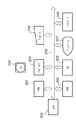
図1は、本発明の実施形態としての印刷制御プログラムを適用可能な情報処理システムの構成を説明するブロック図である。
【0023】
図1において、102〜104はクライアントコンピュータ(以下、クライアントと称する)としての情報処理装置であり、イーサネット(登録商標)などのネットワークケーブルによって、ネットワーク106に接続される。クライアント102〜104の各々は、アプリケーションプログラム等の各種のプログラムを実行可能であり、印刷データをプリンタ言語に変換する機能を有するプリンタドライバを搭載している。ここで、各クライアント102〜104はプリンタドライバを複数登録可能である。なお、図1では例示的に3台のクライアントコンピュータを示しているが、ネットワーク106に接続されているクライアントコンピュータは1台でも、または4台以上でもよい。
【0024】
101はプリントサーバ(図中ではサーバと記している)としての情報処理装置であり、ネットワークケーブルによって、ネットワーク106に接続される。プリントサーバ101は、ネットワークで使用されるファイルを蓄積したり、ネットワーク106の使用状態を監視したりする。また、プリントサーバ101は、ネットワーク106に接続されている複数のプリンタを管理している。
【0025】
なお、クライアント102〜104とプリントサーバ101は、一般的な情報処理装置(いわゆるパーソナルコンピュータなど)に、それぞれ異なる制御を行う印刷制御プログラム(ネットワークプリンタ制御プログラム)を実行可能に格納することで構成することができる。また、プリントサーバ101は、クライアントコンピュータとしての機能を同時に有することもできる。
【0026】
ここで、印刷制御プログラムは、クライアント102〜104において印刷ジョブの印刷先の変更を指示したり、印刷順序の変更を指示するための制御を行うプログラムを含む。また、印刷制御プログラムは、プリントサーバ101において、印刷ジョブの順序制御を行ったり、印刷ジョブの印刷終了や印刷先変更要求などを通知するためのプログラムを含んでいる。ここで印刷制御プログラムは、クライアント102〜104にインストールされるモジュールと、プリントサーバ101にインストールされるモジュールとを別々に含み、情報処理装置の種類に応じていずれかのモジュールをインストールする。しかし、本発明の印刷制御プログラムはこれに限定されるものではなく、一つの印刷制御プログラムが、実行される環境によりクライアント用として機能したり、またはプリントサーバ用として機能するようにしてもよい。あるいは一台のコンピュータに、クライアント用の機能を持つモジュールと、プリントサーバ用として機能するモジュールをともにインストールし、同時に、あるいは時分割で擬似的に並列動作させる構成をとることも可能である。
【0027】
プリントサーバ101は、クライアント102〜104から描画データを含む印刷ジョブを受信してプリンタに印刷させる機能を有する。また、プリントサーバ101は、クライアント102〜104から描画データを含まない印刷ジョブを受け取り、クライアント102〜104の印刷順序を管理し、それぞれのクライアントに対して描画データを含む印刷ジョブの送信許可を順番に通知する機能を有する。更に、プリントサーバ101は、ネットワークプリンタ105のステータスや印刷ジョブの各種情報を取得し、クライアント102〜104に通知する機能を有する。
【0028】
画像形成装置としてのネットワークプリンタ105は、ネットワークインタフェースを介してネットワーク106と接続されている。ネットワークプリンタ105は、クライアントコンピュータ102〜104から送信された、描画データを含む印刷ジョブを解析して1ページずつドットイメージに変換し、1ページ毎に印刷する。
【0029】
また、ネットワークプリンタ105としては、電子写真方式のレーザービームプリンタや複写機やデジタル複合機やファクシミリや、インクジェット方式のプリンタやデジタル複合機など様々な記録方式の画像形成装置を適用できる。
【0030】
プリントサーバ101及びクライント102〜104は同様のハードウェア構成を有した情報処理装置によって実現可能である。図2は、プリントサーバ101またはクライアント102〜105として利用可能な情報処理装置の構成を示すブロック図である。
【0031】
図2において、情報処理装置の制御手段であるCPU200は、ハードディスク(HD)205に格納されているアプリケーションプログラム、プリンタドライバプログラム、OSや印刷制御プログラム等を実行し、RAM202に、プログラムの実行に必要な情報、ファイル等を一時的に格納する制御を行う。
【0032】
ROM201は、その内部に、基本I/Oプログラム等のプログラム、文書処理の際に使用するフォントデータ、テンプレート用データ等の各種データを記憶する。一時記憶手段としてのRAM202は、上述したようにCPU200の主メモリ、ワークエリア等として機能する。
【0033】
フレキシブルディスク(FD)ドライブ203は、記憶媒体としてのFD204に記憶されたプログラム等を本コンピュータシステムにロードすることができる。なお、記憶媒体としてのフレキシブルディスク(FD)204は、コンピュータが読み取り可能なプログラムが格納された記憶媒体である。ここで、記憶媒体としては、FDに限らず、CD−ROM、CD−R、CD−RW、PCカード、DVD、ICメモリカード、MO、メモリスティック等、任意の媒体を利用できる。FD以外の記憶媒体を利用する場合には、その記憶媒体に適したドライブをFDドライブ203の代わりに、或いはFDドライブ203と共に設ければよい。
【0034】
外部記憶装置の一つであり、大容量メモリとして機能するHD(ハードディスク)205には、上述したようにアプリケーションプログラム、プリンタドライバプログラム、OS、印刷制御プログラム、関連プログラム等が格納されている。また、スプール手段であるスプーラもこのHD205に確保される。なお、ここでスプーラとは、クライアント102〜104ではクライアントスプーラのことであり、プリントサーバ101ではサーバスプーラのことである。また、プリントサーバ101では、クライアント102〜104から受けたジョブ情報を格納し、順序制御を行うためのテーブルもこのHD205に生成されて格納される。
【0035】
キーボード206は、ユーザがクライアントコンピュータに対して、或いは、オペレータや管理者がプリントサーバに対して、制御コマンド等を入力するためのものである。なお、指示を入力するために更にポインティングデバイス(不図示)を備えてもよい。
【0036】
ディスプレイ207は、キーボード206から入力したコマンドや、プリンタの状態等を表示する。システムバス208は、情報処理装置内のデータの流れを司る。また、情報処理装置はインタフェース209を介してネットワーク106と接続され、外部装置とのデータのやり取りを行うことが可能となる。
【0037】
図3は、図2に示したRAM202のメモリマップの一例を示す図である。図4は、図2に示したFD204のメモリマップの一例を示す図である。
【0038】
図3において、301は基本I/Oプログラムであり、本制御装置の電源がONされたときに、HD205からOSがRAM202に読み込まれ、OSの動作を開始させるIPL(イニシャルプログラムローデイング)機能などを有しているプログラムが入っている領域である。302はオペレーティングシステム(OS)、303は印刷制御プログラムであり、それぞれRAM202上に確保された領域に記憶される。304は関連データで、RAM202上に確保される領域に記憶される。305はワークエリアで、CPU200が本実施形態のプリンタ制御プログラム(303)等を実行する際に利用される作業領域が確保されている。
【0039】
図4において、401はデータの情報を示すボリューム情報であり、402はディレクトリ情報、403は印刷制御プログラム、404はその関連データである。印刷制御プログラム403は、本実施形態では、クライアント用、サーバ用共に、同様の構成をとっているものとする。
【0040】
図5は、図2に示したFDドライブ203に対して挿入されるFD204との関係を示す図である。例えば、印刷制御プログラムがFD204に格納されている場合には、図5のように、FD204内の印刷制御プログラムがFDドライブ203によって読みとられ、図3のようにRAM202にロードされ、実行可能な状態となる。
【0041】
なお、FD204から印刷制御プログラムおよび関連データを直接RAM202にロードして実行させる以外にも、予めHD205に印刷制御プログラムをインストールしておき、必要な時にHD205からRAM202にロードするようにしてもよい。また、本印刷制御プログラムを記憶する媒体は、FD以外にCD−ROM、CD−R、PCカード、DVD、ICメモリカード等であってもよい。さらに、本印刷制御プログラムをROM201に記憶しておき、これをメモリマップの一部となすように構成し、直接CPU200で実行することも可能である。また、以上の各装置と同等の機能を実現するソフトウェアをもって、ハードウェア装置の代替として構成することもできる。
【0042】
<印刷制御処理>
図6は本実施形態における印刷システムの機能的構成を示すブロック図である。
【0043】
本印刷システムは、プリンタドライバ601、スプーラ602、LPRポート604といった、従来の印刷制御用のモジュールに加えて、新たに、ジョブ制御サービスポートモニタ605、ジョブ制御プリントサービス610、及びプリントマネージャ611を備えたものである。これらのジョブ制御サービスポートモニタ605、ジョブ制御プリントサービス610、及びプリントマネージャ611といった機能は、上述してきた印刷制御プログラムを実行することによって実現される。
【0044】
逆に言えば、本実施形態に係る印刷制御プログラムには、ジョブ制御サービスポートモニタ605、ジョブ制御プリントサービス610、及びプリントマネージャ611といった各機能が含まれる。
【0045】
次に、本印刷システムで行われる印刷処理について説明する。
【0046】
プリンタドライバ601は、OS606(及びアプリケーション607)を介してクライアント102〜104のディスプレイ207にユーザインタフェース608を表示し、ユーザからの印刷設定を受け付ける。そして608を介しての印刷設定が確定すると、この確定した印刷設定に従うアプリケーションからの印刷指示を受け付ける。
【0047】
図8は、クライアント102〜104のディスプレイ207に表示されるユーザインタフェース(印刷設定画面)の一例を示す。801は、クライアント102〜104が選択可能な複数のプリンタリストを示すものであり、図8の状態ではプリンタリスト801から「プリンタE」が選択されるところである。
【0048】
なお、ここでプリンタリストに表示されるのは、画像形成装置としてのプリンタデバイスそのものを表す名称ではなく、どのようにその印刷ジョブを処理するかを示す各種の処理方法である。従って、プリンタリスト801において、例えば、「プリンタC」はPDF(Portable Document Format)(登録商標)ライターを示す場合がある。また、「自動代行」、「同報」は複数のプリンタ(メンバプリンタ)を対象とした印刷を行う為の仮想プリンタを示す。「自動代行」や、「同報」の対象となるメンバプリンタとしては、例えば、プリンタB及びプリンタDを予め登録しておくことができる。
【0049】
図9は、図8において、「プリンタE」の選択が確定した状態でのユーザインタフェースを示す。901は、選択したプリンタに対応するポート名を示す欄である。「プリンタE」のポート名が、Proxy Output PortE(以下、ポートEと称する)であることを示している。尚、HD205には、図8のプリンタリスト801に示される各プリンタと、ポート名とを関連づけるテーブルが格納されており、複数のプリンタから何れかのプリンタが選択されると、図9の901の表示は各々のポートに対応したものとなる。
【0050】
図9に対しユーザからの印刷指示(OKボタンの押下)がキーボード206または不図示のポインティングデバイスから入力されると、図6に戻って、OS606がこれを解釈して描画命令(DDI)としてプリンタドライバ601に送る。プリンタドライバ601はOSを介して供給される描画命令(DDI)に基づき頁記述言語(PDL)で記述された印刷データを生成する。この印刷データにはアプリケーションプログラムが描画した描画データとジョブ制御データの双方が含まれる。
【0051】
生成された印刷データは、OSのスプーラ602によって、スプールファイル(第1スプールファイル)として、スプールファイル記憶エリア603に記憶される。図9で選択されたプリンタに関連付けられたポートがLPRポート604の場合は、LPR(ラインプリンタデーモンプロトコル)を用いてスプーラ602から転送されてきた印刷データが画像形成装置としてのデバイス614に送られる。LPRポート604から転送される印刷データは転送後消去され、再印刷/代行印刷などに利用でいないようになっている。
【0052】
ここで、デバイス614は、図1のネットワークプリンタ105に対応するものであり、上述したとおり、電子写真方式のレーザービームプリンタ/複写機/デジタル複合機/ファクシミリや、インクジェット方式のプリンタ/デジタル複合機など様々な記録方式の画像形成装置が適用できる。
【0053】
一方、プリンタに関連付けられたポートがジョブ制御サービスポートモニタ605を利用するものである場合には、デスプール処理として、ジョブ転送開始通知及び描画データがスプーラ602からジョブ制御サービスポートモニタ605に送られる。そして、ジョブ制御サービスポートモニタ605に送られた描画データはジョブファイル(第2スプールファイル)として、ジョブファイル記憶エリア609に再度スプールされる。
【0054】
なお、ジョブ制御サービスポートモニタ605は、ポート毎に用意されており、それぞれジョブファイル記憶エリア609にジョブファイルを格納する際のデータフォーマットなどの設定を保有している。従って、スプーラ602は、そのジョブがどのポートに対応するものかを判断して、ジョブに応じたジョブ制御サービスポートモニタ605にデスプールする。
【0055】
図7は、スプーラ602からジョブ制御サービスポートモニタ605に送られるジョブ転送開始通知の内容を示す図である。
【0056】
図7において、701はジョブ転送の開始を示し、702はプリンタ名を示す。プリンタ名702は、図8、図9のユーザインタフェースにおいてプリンタリスト801から選択されたプリンタの識別名称に対応する。
【0057】
703は、プリンタリスト801から選択されたプリンタ名に対応するポート名であり、図9の901に示されるポート名と同じ内容となる。
【0058】
704は、印刷指示に応じてOSの仕組みを介して発行されたジョブ識別子としてのID(以下、第1ジョブIDと称する)である。第1ジョブID704はOSを介して発行された印刷指示を識別する為のIDそのものである必要はなく、そのIDに関連付けられていれば良い。
【0059】
ジョブ制御サービスポートモニタ605は、ジョブ制御プリントサービス610に対し、ジョブ開始通知として、受信した図7の情報を通知する。この通知には少なくとも第1ジョブID704が含まれていればよい。第1ジョブID704に関連する他の情報はジョブ制御プリントサービス610が第1ジョブID704をキーに特定できれば良い。
【0060】
これに応じて、ジョブ制御プリントサービス610は、ジョブ制御サービス内部で印刷要求を識別するジョブ識別子としてのID(以下、第2ジョブIDと称する)を生成し、ジョブ制御サービスポートモニタ605に送信する。また、ジョブ制御プリントサービス610は、第2ジョブIDと同時に、ジョブファイル記憶エリア609に描画データを格納する際のファイル名を生成し、ジョブ制御サービスポートモニタ605に送信する。
【0061】
ここで、第1ジョブIDとは別に第2ジョブIDを生成するのは、以下の理由による。
【0062】
OSに管理された第1ジョブIDは、原則的に印刷が終了した時点で開放され、新たに発生した他のジョブに全く同じ第1ジョブIDが付される可能性がある。一方、ジョブ制御プリントサービス610を含む印刷制御プログラムは、一旦終了したジョブのジョブ情報及び描画データを保存しておいて再印刷時に有効に利用しようとするものである。従って、第1ジョブIDだけで管理すると、再印刷時に、同じ第1ジョブIDが付された2つのジョブを区別することができない。そこで、ジョブ制御プリントサービス610は、管理するジョブごとに新たにオリジナルの第2ジョブIDを付して、上記のような問題が生じないようにしている。
【0063】
ジョブ制御プリントサービスポートモニタ605は、スプーラ602から渡された描画データを、順次、ジョブ制御プリントサービス610から指示されたファイル名に関連づけてジョブファイル記憶エリア609に書込む。そして、ジョブ制御プリントサービス610に対し、描画データの書き込み開始を通知する。
【0064】
ジョブ制御プリントサービス610はジョブファイル記憶エリア609への書き込み開始通知を受けると、ジョブファイル記憶エリア609に書込まれた描画データを順次読込み、複数のデバイス614の中で対応するデバイスに送信する。
【0065】
一方、プリントマネージャ611は、一種のアプリケーションであり、API(アプリケーションプログラムインタフェース)612を介してジョブ制御プリントサービス610と各種情報の送受信を行う。この各種情報の送受信には図13中のジョブ識別子が関連付けられているものとする。例えば、プリントマネージャ611は、ジョブ制御プリントサービス610が監視するデバイス614の状態やジョブの状態を反映したユーザインタフェースを作成したり、各種印刷指示の入力画面を提供する。
【0066】
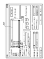
図11は、プリントマネージャ611が表示可能なジョブ一覧画面の一例である。図11の表示には1つのジョブしか示されていないが複数のジョブが表示される場合もある。その場合各々のジョブにはジョブ識別子が関連付けられている。
【0067】
プリントマネージャ611は、ジョブ制御プリントサービス610からプリントジョブの一覧を取得し、図11のようなジョブ一覧画面を、ディスプレイ207に表示することができる。ジョブ一覧画面には、ジョブのプリンタ名(プリンタE)、接続先のポート(Proxy Output PortE)、デバイスの状態等を含むステータス1101を表示する。図においては、「Printer Test Page」というジョブが選択状態にある。
【0068】
また、各ジョブがどのような状態にあるかを、リスト1102にして示す。そして、リスト中のいずれかのジョブを選択して、ポップアップメニュー1103を表示させることにより、そのジョブのキャンセル、停止、再開、再印刷等の指示を行うことができる。ポップアップメニュー1103によるこれらの指示は、選択されたジョブの第2ジョブIDと共にジョブ制御プリントサービス610に送られる。
【0069】
つまり、ジョブ一覧画面に表示された各ジョブは第2ジョブIDと関連づけられているため、一覧画面の中からジョブが選択され、指示が入力されると、そのジョブの第2ジョブIDがプリントマネージャ611からジョブ制御プリントサービス610に送られる。そして、ジョブ制御プリントサービス610は、受け取った第2ジョブIDによってジョブを特定し、再送信や削除などの処理を行う。
【0070】
プリントマネージャ611は、基本的には、このジョブ一覧画面をユーザからの指示に応じて表示するが、ジョブ制御プリントサービス610において認識された画像形成装置への送信が滞るようなエラー発生情報が送られてきたことに応じて、自動的に表示してもよい。
【0071】
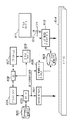
図10は、図6のジョブ制御プリントサービス610の詳細を示すブロック図である。
【0072】
ジョブ出力モジュール1001はジョブ情報をリストにして管理し、印刷データのデバイス614への送信を制御する。
【0073】
デバイス監視モジュール1003はネットワークケーブルなどの通信回線を介してデバイスの状態情報を監視する機能を備える。デバイス監視モジュール1003はデバイスに問合せを行ったり、デバイスから自発的に通知されてくる状態情報を受信する機能を備える。
【0074】
状態情報としては、デバイス614における紙/トナーなどの消耗品無し、ジャム、ドアオープン、等のエラー情報や、デバイス614におけるジョブの予約数などデバイスの負荷情報などを含む。
【0075】
ジョブ管理モジュール1002はデバイス監視モジュール1003とジョブ出力モジュール1001との情報の送受信を仲介する機能を備える。またジョブ制御プリントサービスが、前述のサーバ101上でサーバプログラムとして動作している場合、及び/又は、同一デバイスへ出力される複数のジョブ(ジョブ情報及びジョブファイル)がジョブ出力モジュール中に存在した場合には、それぞれのジョブの送信順序を制御する機能も備える。図10中の双方向矢印1004はスケジュール(出力順序制御)の依頼と、スケジュールアップ(出力開始指示)とを示す。
【0076】
図12はジョブ出力モジュール1001の更に詳細な機能構成を示すブロック図である。図12に示すように、ジョブ出力モジュール1001は、OSのスプーラに登録されているプリンタ及びポート単位でジョブ情報リスト1201を管理するため、各プリンタ及びポートに対応するオブジェクト1208,1209を含んでいる。図12では、それらのオブジェクトの例として、プリンタE、ポートEを示しており、ポートEに対応するデバイスとしてプリンタデバイスEを示している。
【0077】
また、上述したようにジョブ制御サービスポートモニタ605もポート毎に用意されている。このため、スプーラ602からデスプールされたジョブ情報は、そこで指定されているポートに応じて各ジョブ制御サービスポートモニタに振り分けられ、各ジョブ制御サービスポートモニタは、対応するプリンタオブジェクト及びポートオブジェクトとの間で処理を行う。
【0078】
各プリンタオブジェクト1208は、ジョブ情報リスト1201から、ジョブ情報を検索したり、ポートオブジェクト1209にジョブファイルの送信を指示したりする機能を有する。また、各プリンタオブジェクトは、ジョブ制御プリントサービス内部で制御を行う為に必要な拡張情報を保持しており、更にその設定を行うためのユーザインタフェースを表示する機能を有している。図16は、そのような拡張情報を設定するための画面の一例を示す図である。図16に示すように、プリンタオブジェクト1208に設定可能な拡張情報としてはジョブの優先度や代行発生条件がある。
【0079】
一方、各ポートオブジェクト1209は、プリンタオブジェクト1208から送信指示されたジョブの第2ジョブIDを送信待ちジョブのキュー1210へ登録する機能を有する。そして、キュー1210において、最先に登録された第2ジョブIDに対応するジョブファイルをジョブファイル記憶エリア609から読出し、所定のデバイスに送信する機能を有する。
【0080】
ジョブ制御サービスポートモニタ605は、図17に示すユーザインタフェースをディスプレイ207に表示することができ、デバイスのアドレスやモデル名を表示するほか、送信プロトコル、ポート番号、デバイスへの転送方法の設定を受け付けることができる。そして、これらの設定内容のコピーが、ポートオブジェクト1209に予め送られる。
【0081】
従って、図17の「ジョブのデバイスへの転送」チェックボックスにおいて、「スプールしながら転送する」が選択されている場合には、ジョブ制御サービスポートモニタ605によるジョブファイル記憶エリア609へのスプール動作に並行して、ポートオブジェクト1209によるデバイスへの送信処理が行われる。一方、「スプール後に転送する」が選択されている場合は、従来通り、ジョブ制御サービスポートモニタ605がジョブファイル記憶エリア609にジョブに対応する全ての描画データをスプールした後に、デバイスへの転送を開始する。すなわち、印刷制御プログラムは、スプール処理の動作とポートオブジェクトにおける送信処理とを並行動作するか否かを排他的に選択可能である。
【0082】
図17で「スプールしながら転送する」と設定された場合、オペレーションシステムによってスプールファイルとしてスプールされ、一旦デスプールされた印刷データを、更にジョブファイルとして再スプールし、かつ、その再スプール中に、ジョブファイルとして再スプールされた印刷データの一部を読出し、デバイスに送信することになる。
【0083】
なお、1つのデバイスに出力することを目的としたポートオブジェクト1209が複数存在した場合、プリンタオブジェクト1208で受け付けたジョブ情報は、複数のポートオブジェクト1209間において順序制御され順次デバイスへ転送される。
【0084】
なお、ジョブ情報リスト1201に格納される各ジョブ情報の詳細は図13に示されている。ジョブ情報には、第1ジョブIDと第2ジョブIDの対応のほか、ジョブファイルの名称、プリンタ名、ポート名、ジョブの状態、受け付け時刻等が含まれる。ジョブ情報は第2ジョブID、或いはプリンタ名と第1ジョブIDの組み合わせによって検索可能である。ジョブ情報リスト1201は、API612や不図示の内部インタフェースによって、プリンタオブジェクト1208、ポートオブジェクト1209等からアクセス可能に構成されている。なお、ジョブ情報リスト1201はRAM202上に保存され、高速にアクセス可能な構成となっているが、そのコピーはファイルとしてHD205上に保存され、ジョブファイルと共に、装置の電源が切断されても再度利用可能な構成となっている。
【0085】
次に、ジョブ制御サービスポートモニタ605とプリンタオブジェクト1208及びポートオブジェクト1209との間での処理について、図14を用いて詳細に説明する。
【0086】
ユーザインタフェースを介してプリンタEによる印刷指示が入力されると、プリンタE(すなわちポートE)に対応するジョブ制御サービスポートモニタ605は、OSからの印刷開始イベントを認識する(S1401)。
【0087】
次に、ジョブ制御サービスポートモニタ605は、図7に示される情報を含んだジョブ開始要求を、対応するプリンタオブジェクト1208に通知する(S1402)。
【0088】
プリンタオブジェクト1208は、そのジョブ開始要求によって新規にジョブが発行されたことを検知し、ジョブ情報リストから、未使用の第2ジョブID及びジョブファイル記憶エリア609に描画データを記憶する際のファイル名を選択/生成する。そして更に、それらの第2ジョブID及びファイル名を、OSから取得したジョブの属性及び第1ジョブIDと共にジョブ情報リストに登録する。
【0089】
また、ジョブ制御ポートモニタ605は、更新されたジョブ情報リスト1201の中からプリンタ名及び第1ジョブIDをキーとしてジョブ情報を特定し、そのジョブ情報に含まれる第2ジョブID及びファイル名をステップS1402の応答として受け取る(S1403)。
【0090】
次に、ジョブ制御サービスポートモニタ605は、スプーラ602からデスプールされた描画データを、ステップS1403において受信したファイル名を付して、順次、ジョブファイル記憶エリア609へ書き込む(S1409)。そして、第2ジョブIDとジョブファイルの書き込み開始とをプリンタオブジェクト1208へ通知する(S1404)。
【0091】
ステップS1404の通知を受けたプリンタオブジェクト1208は、ステップS1405において、ポートオブジェクト1209に対して第2ジョブIDに対応するジョブの送信予約/登録を行う。これに応じ、ポートオブジェクト1209は、プリンタオブジェクト1208から送信指示されたジョブの第2ジョブIDを送信待ちジョブのキュー1210へ登録する。
【0092】
ポートオブジェクト1209において、「スプールしながら転送する」が設定されている場合、ポートオブジェクト1209は、送信指示を受けたジョブを、ジョブファイルの書込終了シグナルを待たずに、デバイスへの転送候補としてピックアップする。転送候補としてマークされたジョブは、そのジョブに対応するジョブ情報に含まれた優先順位、受付時刻等が参照され、送信順序が決定される。
【0093】
送信待ちジョブのキュー1210に登録されたジョブが送信順序に達すると、ポートオブジェクト1209は、ジョブファイル記憶エリア609から、そのジョブに対応するジョブファイルを読込み、デバイスに送信する(S1406)。ジョブファイルを受信したプリントデバイスでは、受信したジョブファイルに基づいて記録材へのプリントを実行する。
【0094】
ところが、デバイスに対するジョブファイルの送信がエラーによって終了すると、ステップS1407からステップS1408に進み、再送信の指示を待つ。プリンタオブジェクト1208では、再送を指示されると、ステップS1405に戻り、ポートオブジェクト1209に対し、第2ジョブIDに対応するジョブの送信予約を再度行う。そしてステップS1406に進み、更に、ジョブファイル609の読み込み・送信処理が行われる。
【0095】
一方、ジョブ制御サービスポートモニタ605によりジョブファイル609の書き込みが終了した場合には、プリンタオブジェクト1208にジョブファイルの書込終了の同期シグナルが通知される(S1410)。プリンタオブジェクト1208は、書込終了シグナルを受け取ると、確定されたジョブの属性情報(用紙サイズ、用紙枚数等)を元にジョブ情報リスト1201を更新する。
【0096】
書込終了シグナルは、ジョブ制御サービスポートモニタ605からプリンタオブジェクト1208に直接通知しても良いし、セマフォ等を用いて(semaphore:並行して動作しているプロセス間で同期を取ったり割り込み処理の制御を行なう機構。また、そのためにプロセス間で交換される信号)通知しても良い。
【0097】
また、エラー終了することなく書込終了シグナルを検知したプリンタオブジェクト1208及びポートオブジェクト1209は、ジョブの送信処理を正常終了する。
【0098】
デバイスでの印刷完了がデバイス監視モジュール1003によって検知され、ジョブ管理モジュール1002を経由してジョブ出力モジュール1001へ通知されると、ジョブ情報リスト1201からジョブ情報が削除され、ジョブファイル記憶エリア609からジョブファイルが削除され、印刷処理が完了する。
【0099】
<データ転送処理>
図15は、図14のステップS1406におけるジョブデータ送信処理の詳細を示すフローチャートである。このフローチャートに示される各処理はポートオブジェクト1209によって実行される。
【0100】
まず、ステップS1501では、ジョブファイル記憶エリア609において、第2ジョブIDに対応したジョブファイルをオープンする。
【0101】
続いて、ステップS1502において、RAM202上の送信バッファにジョブファイルのデータを記憶する。続いてステップS1503においてジョブファイルの書込終了シグナルがセットされているかを確認する。
【0102】
ステップS1504の判定において、書込終了シグナルがセットされたと判定された場合には、ステップS1505で送信バッファ中のデータが全て転送され、ステップS1506でファイルをクローズして送信処理は終了する。
【0103】
一方、ステップS1504の判定において、書き込みスプール終了シグナルがセットされておらず、まだスプール中であると判定された場合には、ステップS1507に進み、送信バッファに残っている未送信のデータ量を判定する。送信バッファに閾値よりも多くのデータが入っていると判定された場合、ステップS1508において、閾値分のデータだけ送信バッファに残るようにデータを転送する。例えば、閾値が1024バイトで、送信バッファに1124バイトのデータが記憶されている場合には、1124−1024=100バイトだけステップS1508で送信される。
【0104】
ステップS1508の送信処理において、デバイスがデータを受け付けないことが分かった場合には、エラーが発生したと判定し、ステップS1509からステップS1506に進んで、ファイルをクローズし送信処理は終了する。
【0105】
ステップS1509の判定で送信が成功した場合には、ステップS1502に戻り、次のデータを送信バッファに読み込み、送信処理を継続する。
【0106】
一方、ステップS1507におけるデータ量の判定において閾値以下かつ1バイト以上のデータが存在する判定された場合には、ステップS1510において、1バイトのデータのみをデバイス614へ転送する。
【0107】
ステップS1511において送信エラーの発生を判定し、エラーが発生していた場合には、ステップS1506に進み、ファイルをクローズして送信処理を終了する。
【0108】
一方、ステップS1511の判定で送信処理が成功と判定された場合には、ステップS1512において一定時間書込終了シグナルがセットされるのを待つ。ステップS1512はタイムアウトが発生するか、書込終了シグナルがセットされると終了し、
また、ステップS1507の判定でデータが無いと判定された場合には、そのままステップS1502のデータの読み込み処理に戻る。また、別の形態として、ステップS1507の判定でデータが無いと判定された場合には、ステップS1512の処理に移行するようにしても良い。
【0109】
以上の処理によれば、ジョブファイル中における印刷データを、デバイスに対して分割して送信することになるので、再スプールされたジョブファイルを送信するような形態においてインタフェースタイムアウトの発生を回避できることになる。
【0110】
また、ジョブファイルのスプールの終了を監視し、スプールファイルの書込終了が検知されていない場合に、印刷データをデバイスに対して分割して送信するようにし、書込終了が検知された場合に送信バッファ中のデータを全て転送するようにするので、ジョブ制御サービスポートモニタ605を介してのジョブファイルのスプールが滞っている可能性のケースに対応して効率よくインタフェースタイムアウトの発生を回避できできることになる。
【0111】
また、ジョブファイルにおいて、デバイスに対して未送信のデータ量を検知し、検知された未送信データ量が所定の閾値以下か否かを判定し、未送信データ量が前記閾値以下と判定された場合に、閾値の整数分の1のデータ量のみをデバイスに送信することになる。また、データ量が閾値より多いと判定するまで、デバイスにおけるインタフェースタイムアウトが発生する時間未満の間隔で、分割送信を繰り返し実行することになる。
【0112】
なお、ステップS1507の判定に利用する閾値及びステップS1512におけるシグナル待ち時間は、予め設定されたインタフェースタイムアウト防止時間及びデバイス614のインタフェースタイムアウト時間によって決定される。例えば、デバイスにおいて1分間のインタフェースタイムアウト時間が設定されている場合、ステップS1512において書込終了イベントを待つ時間は、デバイスのインタフェースタイムアウト時間以下の値(例えば40秒)に設定される。この書込終了イベント待ち時間は、デバイスのインタフェースタイムアウト時間よりも十分に少ない時間であることが望ましい。
【0113】
例えば、ステップS1512における書込終了イベントの待ち時間が30秒で、インタフェースタイムアウトを10分(600秒)間防止したい場合には、閾値として600÷30=20バイトを設定すればよいことになる。これらの値は本印刷システムがサポートする全デバイスの特性を考慮してシステム全体で一意に決定し、ROM201に保持しても良いし、デバイス毎に個別の設定をROM201或いはHD205等に保持しても良い。またタイムアウト設定画面を表示し、閾値や書込終了シグナル待ち時間などについてユーザの任意の設定を受け付けるタイムアウト設定手段を設けてもよい。その場合、デバイス毎或いはシステムで一意のタイムアウト設定は、HD205等の不揮発性メモリに保存することが望ましい。
【0114】
また、前述の説明においてステップS1510ではタイムアウト防止用に1バイトのデータを分割送信したが、本発明はこれに限定されるものではなく、他の所定量のデータ(例えば、閾値の整数分の1のデータ)に分割して送信してもよい。例えば、1回の分割送信のバイト数を16バイトとした場合には、閾値を320バイトとすれば、送信バッファ内のデータが閾値以下になってから全くジョブファイルにデータが記憶されなくても、320÷16=20回、ステップS1512の待機処理が行われる。これによって1回の書込終了イベントの待ち時間が30秒であれば、30×20=600秒、つまり10分間のインタフェースタイムアウト時間が保証される。
【0115】
なお、ここでは閾値を1つにして、閾値以下の場合に1バイトずつ送信するアルゴリズムとしたが、本発明はこれに限定されるものではなく、複数の閾値を設け、データサイズに応じて様々なデータ量に分割するアルゴリズムでもかまわない。
【0116】
ステップS1512の待機処理が繰り返されても、スプーラ602からジョブ制御ポートモニタ605への描画データの転送が滞った場合には、デバイスとのインタフェースにおいてインタフェースタイムアウトが発生する。このような場合や、デバイスの電源断等が発生しデバイスがデータを受け付けない場合には、ステップS1509またはステップS1511においてエラーと判定し、送信処理が終了する。
【0117】
なお、本実施形態においては、印刷データの再送を、図11に示したジョブ一覧画面におけるユーザからの指示によって実施することとしたが、本発明はこれに限定されるものではなく、例えばプリントマネージャ611等のジョブ制御プリントサービス610を監視するプログラムが、ジョブの状態を常時監視し、ジョブエラーの発生後、自動的に再送指示を行ってもよい。このポートオブジェクト1209に対する再送指示は、ジョブエラー発生の一定時間後であってもよいし、エラーとなったジョブのジョブファイル生成が完了した時点であってもよい。
【0118】
(他の実施形態)
以上、本発明の実施形態について詳述したが、本発明は、複数の機器から構成されるシステムに適用しても良いし、また、一つの機器からなる装置に適用しても良い。
【0119】
なお、本発明は、前述した実施形態の機能を実現するソフトウェアのプログラム(上記実施形態では図14や図15に示すフローチャートに対応したプログラム)を、システム或いは装置に直接或いは遠隔から供給し、そのシステム或いは装置のコンピュータが該供給されたプログラムコードを読み出して実行することによっても達成される場合を含む。その場合、プログラムの機能を有していれば、形態は、プログラムである必要はない。
【0120】
従って、本発明の機能処理をコンピュータで実現するために、該コンピュータにインストールされるプログラムコード自体も本発明を実現するものである。つまり、本発明のクレームでは、本発明の機能処理を実現するためのコンピュータプログラム自体も含まれる。
【0121】
その場合、プログラムの機能を有していれば、オブジェクトコード、インタプリタにより実行されるプログラム、OSに供給するスクリプトデータ等、プログラムの形態を問わない。
【0122】
プログラムを供給するための記録媒体としては、例えば、フロッピー(登録商標)ディスク、ハードディスク、光ディスク、光磁気ディスク、MO、CD−ROM、CD−R、CD−RW、磁気テープ、不揮発性のメモリカード、ROM、DVD(DVD−ROM,DVD−R)などがある。
【0123】
その他、プログラムの供給方法としては、クライアントコンピュータのブラウザを用いてインターネットのホームページに接続し、該ホームページから本発明のコンピュータプログラムそのもの、もしくは圧縮され自動インストール機能を含むファイルをハードディスク等の記録媒体にダウンロードすることによっても供給できる。また、本発明のプログラムを構成するプログラムコードを複数のファイルに分割し、それぞれのファイルを異なるホームページからダウンロードすることによっても実現可能である。つまり、本発明の機能処理をコンピュータで実現するためのプログラムファイルを複数のユーザに対してダウンロードさせるWWWサーバも、本発明のクレームに含まれるものである。
【0124】
また、本発明のプログラムを暗号化してCD−ROM等の記憶媒体に格納してユーザに配布し、所定の条件をクリアしたユーザに対し、インターネットを介してホームページから暗号化を解く鍵情報をダウンロードさせ、その鍵情報を使用することにより暗号化されたプログラムを実行してコンピュータにインストールさせて実現することも可能である。
【0125】
また、コンピュータが、読み出したプログラムを実行することによって、前述した実施形態の機能が実現される他、そのプログラムの指示に基づき、コンピュータ上で稼動しているOSなどが、実際の処理の一部または全部を行ない、その処理によっても前述した実施形態の機能が実現され得る。
【0126】
さらに、記録媒体から読み出されたプログラムが、コンピュータに挿入された機能拡張ボードやコンピュータに接続された機能拡張ユニットに備わるメモリに書き込まれた後、そのプログラムの指示に基づき、その機能拡張ボードや機能拡張ユニットに備わるCPUなどが実際の処理の一部または全部を行ない、その処理によっても前述した実施形態の機能が実現される。
【0127】
【発明の効果】
以上説明したように、本発明によれば、再スプールファイルを利用することにより印刷データのプリンタへの転送を行うような仕組みにおいて、インタフェースタイムアウトエラーの発生を防止する印刷制御の仕組みを提供することが可能となる。
【0128】
またインタフェースタイムアウトが発生した場合においても速やかに再送をおこなうことが可能となる。
【図面の簡単な説明】
【図1】本発明の実施形態に係る印刷処理システムの構成を示す図である。
【図2】本発明の実施形態に係る印刷処理システムにおける情報処理装置の構成を示すブロック図である。
【図3】本発明の実施形態に係る情報処理装置のRAMのメモリマップの一例を示す図である。
【図4】本発明の実施形態に係るFDのメモリマップの一例を示す図である。
【図5】本発明の実施形態に係る情報処理装置のFDドライブに挿入されるFDとの関係を示す図である。
【図6】本発明の実施形態に係る情報処理装置の印刷制御機能の概略を示す図である。
【図7】本発明の実施形態に係る通知情報の一例を示す図である。
【図8】本発明の実施形態に係る印刷設定画面の一例を示す図である。
【図9】本発明の実施形態に係る印刷設定画面の一例を示す図である。
【図10】本発明の実施形態に係る情報処理装置の印刷制御機能の詳細を示す図である。
【図11】本発明の実施形態に係る印刷設定画面の一例を示す図である。
【図12】本発明の実施形態に係る情報処理装置の印刷制御機能の詳細を示す図である。
【図13】本発明の実施形態に係るジョブ情報の一例を示す図である。
【図14】本発明の実施形態に係る印刷制御処理を示すフローチャートである。
【図15】本発明の実施形態に係る印刷制御処理を示すフローチャートである。
【図16】本発明の実施形態に係る印刷設定画面の一例を示す図である。
【図17】本発明の実施形態に係る印刷設定画面の一例を示す図である。[0001]
BACKGROUND OF THE INVENTION
The present invention relates to a technique for transmitting print data to an image forming apparatus.
[0002]
[Prior art]
2. Description of the Related Art Conventionally, there is known a transfer technique for sequentially transferring data written as a spool file via an operation system (OS) such as Windows (registered trademark) to an image forming apparatus without waiting for completion of spooling. .
[0003]
In addition, a print control unique spool file is created separately from the print spool file created by the OS mechanism such as Windows (registered trademark), and this re-print spool file is used when reprinting becomes necessary. The technology to do is known.
[0004]
For example,
[0005]
[Patent Document 1]
JP 2002-196916 A
[0006]
[Problems to be solved by the invention]
However, in the prior art, since the transfer to the image forming apparatus is started before the printing process of the application (spool processing to the OS) is completed, if the print data generation process in the application or the printer driver is delayed, the transfer to the OS When the spool process is in a standby state and the wait time is long, printing may not be completed due to an interface timeout.
[0008]
The present invention has been made in view of the above problems,ReBy using a spool file, print dataTo the printerPrevents interface timeout errors from occurring in mechanisms that perform forwardingDoThe object is to provide a mechanism for printing control.
[0009]
[Means for Solving the Problems]
In order to achieve the above object, a program according to the present invention provides print data to an image forming apparatus.outputA print control program executed in an information processing apparatus for recording an image,
In the information processing apparatus,
A spool step of re-spooling the print data spooled as the first spool file by the operation system as the second spool file;
Respool in the spool stepAccording to the delayA part of the print data respooled as the second spool file is read out to the image forming apparatusoutputDooutputAnd executing the step.
[0010]
In addition to the information processing apparatus,
Associating a second job identifier different from the first job identifier issued corresponding to the print data with the print data to be respooled in the spool step;
And a management step for performing job management based on the second job identifier.
[0011]
The first job identifier is an identifier issued through the operation system.
[0012]
SaidoutputThe step divides print data in the second spool file with respect to the image forming apparatus.Split toIncluding steps.
[0013]
In addition to the information processing apparatus,
A write end detection step for detecting the end of spooling of the second spool file in the spool step;Let it run,
SaidSplitThe step of printing the print data in the second spool file when the writing end of the spool file is not detected by the writing end detecting step;SplitIt is characterized by doing.
[0014]
In addition to the information processing apparatus,
In the second spool file, the non-printed image forming apparatusoutputThe steps are
The print data in the second spool file is divided with respect to the image forming apparatusSplit toA data amount detecting step for detecting the amount of data characterized by including a step;
A determination step of determining whether the data amount detected in the data amount detection step is equal to or less than a predetermined threshold;And execute
The output step includesPrint data in the second spool file when the data amount is determined to be equal to or less than the threshold value in the determination step.Part ofFor the image forming apparatusOutputIt is characterized by that.
[0015]
SaidoutputThe step is an interval less than the time at which an interface timeout occurs in the image forming apparatus until it is determined in the determination step that the data amount is greater than the threshold.Output part of the print dataIs repeatedly executed.
[0016]
In the information processing apparatus, the print data respooled as the second spool file in the spool step is transferred to the image forming apparatus.outputIf the print data is re-spooled even if re-spooling of the spool step is not completed,outputDo reoutputThe step is further executed.
[0017]
In the information processing apparatus,
Displays the status of the print data respooled as the second spool file in the spool step.DisplayDisplaycontrolSteps,
errorTo the image forming apparatusoutputHas been interruptedPrint dataReoutputAccepting instructions, andFurther executionIt is characterized by that.
[0018]
Said reoutputThe steps are
ReoutputA specific step of specifying print data to be printed by the second job identifier is included.
[0019]
In order to achieve the above object, a storage medium according to the present invention stores the above print control program.
[0020]
In order to achieve the above object, an apparatus according to the present invention transmits print data to an image forming apparatus.outputAn information processing apparatus for recording an image,
Spool means for re-spooling the print data spooled as the first spool file by the operation system as the second spool file;
Respooling by the spool meansAccording to the delayA part of the print data respooled as the second spool file is read out to the image forming apparatusoutputDooutputAnd means.
[0021]
DETAILED DESCRIPTION OF THE INVENTION
Hereinafter, exemplary embodiments of the present invention will be described in detail with reference to the drawings. However, the relative arrangement of components, the display screen, and the like described in this embodiment are not intended to limit the scope of the present invention only to those unless otherwise specified.
[0022]
(First embodiment)
<System configuration>
FIG. 1 is a block diagram illustrating a configuration of an information processing system to which a print control program as an embodiment of the present invention can be applied.
[0023]
In FIG. 1, reference numerals 102 to 104 denote information processing apparatuses as client computers (hereinafter referred to as clients), which are connected to the network 106 by a network cable such as Ethernet (registered trademark). Each of the clients 102 to 104 can execute various programs such as an application program, and has a printer driver having a function of converting print data into a printer language. Here, each of the clients 102 to 104 can register a plurality of printer drivers. In FIG. 1, three client computers are exemplarily shown, but the number of client computers connected to the network 106 may be one, or four or more.
[0024]
An information processing apparatus 101 is a print server (denoted as a server in the figure), and is connected to the network 106 by a network cable. The print server 101 accumulates files used on the network and monitors the use state of the network 106. The print server 101 manages a plurality of printers connected to the network 106.
[0025]
The clients 102 to 104 and the print server 101 are configured by executably storing print control programs (network printer control programs) for performing different controls in general information processing apparatuses (so-called personal computers). be able to. The print server 101 can also have a function as a client computer at the same time.
[0026]
Here, the print control program includes a program for instructing the client 102 to 104 to change the print destination of the print job or to instruct to change the print order. The print control program includes a program for controlling the order of print jobs in the print server 101 and notifying the end of printing of a print job, a request for changing the print destination, and the like. Here, the print control program separately includes modules installed in the clients 102 to 104 and modules installed in the print server 101, and installs any one of the modules according to the type of the information processing apparatus. However, the print control program of the present invention is not limited to this, and one print control program may function as a client or a print server depending on the environment in which it is executed. Alternatively, a module having a function for a client and a module functioning for a print server may be installed in one computer, and may be configured to operate in parallel in a pseudo manner in a time division manner.
[0027]
The print server 101 has a function of receiving a print job including drawing data from the clients 102 to 104 and printing it on a printer. Also, the print server 101 receives print jobs that do not include drawing data from the clients 102 to 104, manages the printing order of the clients 102 to 104, and sequentially grants permission to send print jobs including drawing data to each client. It has a function to notify. Further, the print server 101 has a function of acquiring the status of the network printer 105 and various information of the print job and notifying the clients 102 to 104.
[0028]
A network printer 105 as an image forming apparatus is connected to a network 106 via a network interface. The network printer 105 analyzes the print job including the drawing data transmitted from the client computers 102 to 104, converts it into a dot image page by page, and prints it for each page.
[0029]
Further, as the network printer 105, image forming apparatuses of various recording methods such as an electrophotographic laser beam printer, a copying machine, a digital multifunction peripheral, a facsimile, an ink jet printer, and a digital multifunction peripheral can be applied.
[0030]
The print server 101 and the clients 102 to 104 can be realized by an information processing apparatus having a similar hardware configuration. FIG. 2 is a block diagram illustrating a configuration of an information processing apparatus that can be used as the print server 101 or the clients 102 to 105.
[0031]
In FIG. 2, a
[0032]
The
[0033]
A flexible disk (FD) drive 203 can load a program or the like stored in the
[0034]
As described above, an HD (hard disk) 205, which is one of external storage devices and functions as a large-capacity memory, stores an application program, a printer driver program, an OS, a print control program, related programs, and the like. Further, a spooler which is a spool means is also secured in this
[0035]
A
[0036]
A
[0037]
FIG. 3 is a diagram showing an example of a memory map of the
[0038]
In FIG. 3,
[0039]
In FIG. 4, 401 is volume information indicating data information, 402 is directory information, 403 is a print control program, and 404 is related data. In the present embodiment, the
[0040]
FIG. 5 is a diagram showing a relationship with the
[0041]
In addition to directly loading the print control program and related data from the
[0042]
<Print control processing>
FIG. 6 is a block diagram showing a functional configuration of the printing system in the present embodiment.
[0043]
The printing system includes a job control
[0044]
In other words, the print control program according to the present embodiment includes functions such as a job control
[0045]
Next, a printing process performed in the printing system will be described.
[0046]
The
[0047]
FIG. 8 shows an example of a user interface (print setting screen) displayed on the
[0048]
Here, what is displayed in the printer list is not a name representing the printer device itself as the image forming apparatus, but various processing methods indicating how the print job is processed. Accordingly, in the
[0049]
FIG. 9 shows a user interface in a state where the selection of “printer E” in FIG. 8 is confirmed.
[0050]
When a print instruction (pressing the OK button) from the user is input from the
[0051]
The generated print data is stored in the spool
[0052]
Here, the
[0053]
On the other hand, if the port associated with the printer uses the job control
[0054]
Note that the job control service port monitor 605 is prepared for each port, and has settings such as a data format when the job file is stored in the job
[0055]
FIG. 7 is a diagram showing the contents of the job transfer start notification sent from the
[0056]
In FIG. 7, 701 indicates the start of job transfer, and 702 indicates a printer name. The
[0057]
[0058]
[0059]
The job control service port monitor 605 notifies the job
[0060]
In response to this, the job
[0061]
Here, the second job ID is generated separately from the first job ID for the following reason.
[0062]
The first job ID managed by the OS is basically released when printing is completed, and there is a possibility that the same first job ID may be assigned to another newly generated job. On the other hand, the print control program including the job
[0063]
The job control print service port monitor 605 sequentially writes the drawing data passed from the
[0064]
When the job
[0065]
On the other hand, the
[0066]
FIG. 11 is an example of a job list screen that can be displayed by the
[0067]
The
[0068]
In addition, a
[0069]
That is, since each job displayed on the job list screen is associated with the second job ID, when a job is selected from the list screen and an instruction is input, the second job ID of the job is set to the print manager. 611 to the job
[0070]
The
[0071]
FIG. 10 is a block diagram showing details of the job
[0072]
The
[0073]
The
[0074]
The status information includes error information such as no paper / toner consumables in the
[0075]
The
[0076]
FIG. 12 is a block diagram showing a more detailed functional configuration of the
[0077]
As described above, the job control service port monitor 605 is also prepared for each port. For this reason, the job information despooled from the
[0078]
Each
[0079]
On the other hand, each
[0080]
The job control service port monitor 605 can display the user interface shown in FIG. 17 on the
[0081]
Accordingly, when “transfer while spooling” is selected in the “transfer job to device” check box in FIG. 17, the job control service port monitor 605 performs a spool operation to the job
[0082]
When “transfer while spooling” is set in FIG. 17, the print data spooled as a spool file by the operation system and despooled once is further respooled as a job file. A part of the print data respooled as a file is read and transmitted to the device.
[0083]
When there are a plurality of
[0084]
Details of each piece of job information stored in the
[0085]
Next, processing between the job control
[0086]
When a print instruction from the printer E is input via the user interface, the job control service port monitor 605 corresponding to the printer E (that is, port E) recognizes a print start event from the OS (S1401).
[0087]
Next, the job control service port monitor 605 notifies the corresponding
[0088]
The
[0089]
Also, the job control port monitor 605 identifies job information from the updated
[0090]
Next, the job control service port monitor 605 writes the drawing data despooled from the
[0091]
Upon receiving the notification in step S1404, the
[0092]
When “transfer while spooling” is set in the
[0093]
When the job registered in the
[0094]
However, when the transmission of the job file to the device is terminated due to an error, the process proceeds from step S1407 to step S1408, and a retransmission instruction is waited. When the
[0095]
On the other hand, when the job control service port monitor 605 finishes writing the
[0096]
The write end signal may be notified directly from the job control service port monitor 605 to the
[0097]
Further, the
[0098]
When the
[0099]
<Data transfer processing>
FIG. 15 is a flowchart showing details of the job data transmission process in step S1406 of FIG. Each process shown in this flowchart is executed by the
[0100]
First, in step S1501, a job file corresponding to the second job ID is opened in the job
[0101]
In step S1502, the job file data is stored in the transmission buffer on the
[0102]
If it is determined in step S1504 that the write end signal has been set, all the data in the transmission buffer is transferred in step S1505, the file is closed in step S1506, and the transmission process ends.
[0103]
On the other hand, if it is determined in step S1504 that the write spool end signal is not set and it is determined that spooling is still in progress, the process advances to step S1507 to determine the amount of untransmitted data remaining in the transmission buffer. To do. If it is determined that there is more data than the threshold in the transmission buffer, in step S1508, the data is transferred so that only data corresponding to the threshold remains in the transmission buffer. For example, if the threshold is 1024 bytes and 1124 bytes of data are stored in the transmission buffer, 1124-1024 = 100 bytes are transmitted in step S1508.
[0104]
If it is determined in the transmission process in step S1508 that the device does not accept data, it is determined that an error has occurred, the process advances from step S1509 to step S1506, the file is closed, and the transmission process ends.
[0105]
If transmission is successful in step S1509, the process returns to step S1502, reads the next data into the transmission buffer, and continues the transmission process.
[0106]
On the other hand, if it is determined in step S1507 that there is data that is equal to or less than the threshold and 1 byte or more in step S1507, only 1 byte of data is transferred to the
[0107]
In step S1511, it is determined that a transmission error has occurred. If an error has occurred, the process advances to step S1506 to close the file and end the transmission process.
[0108]
On the other hand, if it is determined in step S1511 that the transmission process is successful, the process waits for the writing end signal to be set for a predetermined time in step S1512. Step S1512 ends when a timeout occurs or a write end signal is set,
If it is determined in step S1507 that there is no data, the process returns to the data reading process in step S1502. As another form, when it is determined in step S1507 that there is no data, the process may proceed to step S1512.
[0109]
According to the above processing, the print data in the job file is divided and transmitted to the device, so that it is possible to avoid occurrence of an interface timeout in a form in which the respooled job file is transmitted. Become.
[0110]
Also, the end of spooling of the job file is monitored, and when the end of writing the spool file is not detected, the print data is divided and transmitted to the device. When the end of writing is detected Since all the data in the transmission buffer is transferred, it is possible to efficiently avoid the occurrence of an interface timeout corresponding to the case where the spool of the job file via the job control service port monitor 605 may be stagnant. become.
[0111]
Also, in the job file, the amount of untransmitted data to the device is detected, it is determined whether the detected amount of untransmitted data is equal to or less than a predetermined threshold, and the amount of untransmitted data is determined to be equal to or less than the threshold. In this case, only the data amount of 1 / integer of the threshold is transmitted to the device. Further, until the data amount is determined to be larger than the threshold value, the divided transmission is repeatedly executed at an interval less than the time when the interface timeout occurs in the device.
[0112]
Note that the threshold used for the determination in step S1507 and the signal waiting time in step S1512 are determined by a preset interface timeout prevention time and the interface timeout time of the
[0113]
For example, if the waiting time of the write end event in step S1512 is 30 seconds and it is desired to prevent the interface timeout for 10 minutes (600 seconds), 600 ÷ 30 = 20 bytes may be set as the threshold value. These values are uniquely determined for the entire system in consideration of the characteristics of all devices supported by this printing system, and may be stored in the
[0114]
In the above description, 1-byte data is divided and transmitted in order to prevent timeout in step S1510. However, the present invention is not limited to this, and other predetermined amount of data (for example, 1 / integer of the threshold value). Data) may be divided and transmitted. For example, if the number of bytes for one divided transmission is 16 bytes, if the threshold is set to 320 bytes, no data is stored in the job file after the data in the transmission buffer falls below the threshold. 320 ÷ 16 = 20 times, the standby process of step S1512 is performed. As a result, if the waiting time of one write end event is 30 seconds, 30 × 20 = 600 seconds, that is, an interface timeout time of 10 minutes is guaranteed.
[0115]
Here, the algorithm is such that one threshold value is transmitted and one byte is transmitted when the threshold value is equal to or less than the threshold value. However, the present invention is not limited to this, and a plurality of threshold values are provided. It is possible to use an algorithm that divides the data into various data amounts.
[0116]
Even if the standby processing in step S1512 is repeated, if drawing data transfer from the
[0117]
In this embodiment, the print data is retransmitted according to an instruction from the user on the job list screen shown in FIG. 11, but the present invention is not limited to this. For example, the print manager A program for monitoring the job
[0118]
(Other embodiments)
Although the embodiments of the present invention have been described in detail above, the present invention may be applied to a system constituted by a plurality of devices or may be applied to an apparatus constituted by one device.
[0119]
In the present invention, a software program that realizes the functions of the above-described embodiments (in the above-described embodiment, a program corresponding to the flowcharts shown in FIGS. 14 and 15) is directly or remotely supplied to a system or apparatus. This includes the case where the object is also achieved by reading and executing the supplied program code by the computer of the system or apparatus. In that case, as long as it has the function of a program, the form does not need to be a program.
[0120]
Accordingly, since the functions of the present invention are implemented by computer, the program code installed in the computer also implements the present invention. That is, the claims of the present invention include the computer program itself for realizing the functional processing of the present invention.
[0121]
In this case, the program may be in any form as long as it has a program function, such as an object code, a program executed by an interpreter, or script data supplied to the OS.
[0122]
As a recording medium for supplying the program, for example, floppy (registered trademark) disk, hard disk, optical disk, magneto-optical disk, MO, CD-ROM, CD-R, CD-RW, magnetic tape, nonvolatile memory card ROM, DVD (DVD-ROM, DVD-R) and the like.
[0123]
As another program supply method, a client computer browser is used to connect to an Internet homepage, and the computer program of the present invention itself or a compressed file including an automatic installation function is downloaded from the homepage to a recording medium such as a hard disk. Can also be supplied. It can also be realized by dividing the program code constituting the program of the present invention into a plurality of files and downloading each file from a different homepage. That is, a WWW server that allows a plurality of users to download a program file for realizing the functional processing of the present invention on a computer is also included in the claims of the present invention.
[0124]
In addition, the program of the present invention is encrypted, stored in a storage medium such as a CD-ROM, distributed to users, and key information for decryption is downloaded from a homepage via the Internet to users who have cleared predetermined conditions. It is also possible to execute the encrypted program by using the key information and install the program on a computer.
[0125]
In addition to the functions of the above-described embodiments being realized by the computer executing the read program, the OS running on the computer based on an instruction of the program is a part of the actual processing. Alternatively, the functions of the above-described embodiment can be realized by performing all of them and performing the processing.
[0126]
Furthermore, after the program read from the recording medium is written in a memory provided in a function expansion board inserted into the computer or a function expansion unit connected to the computer, the function expansion board or The CPU or the like provided in the function expansion unit performs part or all of the actual processing, and the functions of the above-described embodiments are realized by the processing.
[0127]
【The invention's effect】
As explained above, according to the present invention,Provides a print control mechanism that prevents the occurrence of an interface timeout error in a mechanism that transfers print data to a printer by using a respool file.It becomes possible.
[0128]
In addition, even when an interface timeout occurs, it is possible to perform retransmission quickly.
[Brief description of the drawings]
FIG. 1 is a diagram illustrating a configuration of a print processing system according to an embodiment of the present invention.
FIG. 2 is a block diagram showing a configuration of an information processing apparatus in the print processing system according to the embodiment of the present invention.
FIG. 3 is a diagram showing an example of a RAM memory map of the information processing apparatus according to the embodiment of the present invention.
FIG. 4 is a diagram showing an example of a memory map of the FD according to the embodiment of the present invention.
FIG. 5 is a diagram showing a relationship with an FD inserted into an FD drive of the information processing apparatus according to the embodiment of the present invention.
FIG. 6 is a diagram showing an outline of a print control function of the information processing apparatus according to the embodiment of the present invention.
FIG. 7 is a diagram showing an example of notification information according to the embodiment of the present invention.
FIG. 8 is a diagram showing an example of a print setting screen according to the embodiment of the present invention.
FIG. 9 is a diagram showing an example of a print setting screen according to the embodiment of the present invention.
FIG. 10 is a diagram showing details of a print control function of the information processing apparatus according to the embodiment of the present invention.
FIG. 11 is a diagram showing an example of a print setting screen according to the embodiment of the present invention.
FIG. 12 is a diagram showing details of a print control function of the information processing apparatus according to the embodiment of the present invention.
FIG. 13 is a diagram showing an example of job information according to the embodiment of the present invention.
FIG. 14 is a flowchart illustrating print control processing according to the embodiment of the present invention.
FIG. 15 is a flowchart illustrating print control processing according to the embodiment of the present invention.
FIG. 16 is a diagram showing an example of a print setting screen according to the embodiment of the present invention.
FIG. 17 is a diagram showing an example of a print setting screen according to the embodiment of the present invention.
Claims (23)
前記情報処理装置に、
オペレーションシステムによって第1スプールファイルとしてスプールされた印刷データを、更に第2スプールファイルとして再スプールするスプールステップと、
前記スプールステップにおける再スプールが滞ることに応じて、前記第2スプールファイルとして再スプールされた印刷データの一部を読出し、前記画像形成装置に出力する出力ステップと、
を実行させることを特徴とする印刷制御プログラム。A print control program executed in an information processing apparatus that outputs print data to an image forming apparatus and records an image,
In the information processing apparatus,
A spool step of re-spooling the print data spooled as the first spool file by the operation system as the second spool file;
An output step in response to the re-spooling stagnates in the spool step to output a portion of the print data respool read, in the image forming apparatus as the second spool file,
A print control program for executing
前記印刷データに対応して発行される第1ジョブ識別子とは異なる第2ジョブ識別子を、前記スプールステップにおいて再スプールされる印刷データに関連づけるステップと、
前記第2ジョブ識別子に基づくジョブ管理を行う管理ステップと、
を実行させることを特徴とする請求項1に記載の印刷制御プログラム。In addition to the information processing apparatus,
Associating a second job identifier different from the first job identifier issued corresponding to the print data with the print data to be respooled in the spool step;
A management step for performing job management based on the second job identifier;
The print control program according to claim 1, wherein the print control program is executed.
前記第2スプールファイル中における印刷データを、前記画像形成装置に対して分割する分割ステップを含むことを特徴とする請求項1乃至3のいずれかに記載の印刷制御プログラム。The output step includes
4. The print control program according to claim 1, further comprising a dividing step of dividing print data in the second spool file with respect to the image forming apparatus.
前記スプールステップにおいて前記第2スプールファイルのスプールの終了を検知する書込終了検知ステップを実行させ、
前記分割ステップは、前記書込終了検知ステップによってスプールファイルの書込終了が検知されていない場合に、前記第2スプールファイル中における印刷データを分割することを特徴とする請求項4に記載の印刷制御プログラム。 In addition to the information processing apparatus,
To execute the write end detection step for detecting the end of the spool of the second spool file in the spool step,
5. The printing according to claim 4, wherein the dividing step divides the print data in the second spool file when the writing end of the spool file is not detected by the writing end detecting step. Control program.
前記第2スプールファイルにおいて、前記画像形成装置に対して未出力のデータ量を検知するデータ量検知ステップと、
前記データ量検知ステップで検知されたデータ量が所定の閾値以下か否かを判定する判定ステップと、を実行させ、
前記出力ステップは、前記判定ステップで前記データ量が前記閾値以下と判定された場合に、前記第2スプールファイル中における印刷データの一部を、前記画像形成装置に対して出力することを特徴とする請求項1乃至5の何れかに記載の印刷制御プログラム。 In addition to the information processing apparatus,
A data amount detection step of detecting a data amount not yet output to the image forming apparatus in the second spool file;
A determination step of determining whether or not the data amount detected in the data amount detection step is equal to or less than a predetermined threshold ; and
Said output step includes a wherein when said data amount determining step is less than or equal to the threshold value, a part of the print data in said second spooling file, and outputs to the image forming apparatus A printing control program according to any one of claims 1 to 5 .
前記判定ステップで前記データ量が前記閾値より多いと判定するまで、前記画像形成装置におけるインタフェースタイムアウトが発生する時間未満の間隔で、前記印刷データの一部の出力を繰り返し実行することを特徴とする請求項6に記載の印刷制御プログラム。The output step includes
The output of a part of the print data is repeatedly executed at an interval less than a time when an interface timeout occurs in the image forming apparatus until it is determined in the determination step that the data amount is larger than the threshold value. The printing control program according to claim 6.
前記スプールステップにおいて第2スプールファイルとして再スプールされた前記印刷データの前記画像形成装置への出力が滞った場合に、前記スプールステップの再スプールが完了していなくても、前記印刷データの再出力を行う再出力ステップを更に実行させることを特徴とする請求項1乃至7のいずれかに記載の印刷制御プログラム。In the information processing apparatus,
If the output of the said spool step to the image forming apparatus of the print data re-spooled as the second spool file is stuck, even without re-spool completion of the spool step, re-output of the print data The print control program according to claim 1, further comprising executing a re- output step of performing the step.
前記スプールステップにおいて第2スプールファイルとして再スプールされた印刷データの状態を表示部に表示させる表示制御ステップと、
エラーによって前記画像形成装置への出力が中断している印刷データの再出力指示を受け付けるステップと、
を更に実行させることを特徴とする請求項8に記載の印刷制御プログラム。 In the information processing apparatus,
A display control step of Ru to display the status of the print data respool on the display unit as the second spool file in the spool step,
A step of receiving re-output instruction of the print data output to the image forming apparatus is interrupted due to an error,
The print control program according to claim 8, further comprising:
再出力すべき印刷データを前記第2ジョブ識別子によって特定する特定ステップを含むことを特徴とする請求項8又は9に記載の印刷制御プログラム。The re- output step includes
The print control program according to claim 8 , further comprising a specifying step of specifying print data to be re- output based on the second job identifier.
オペレーションシステムによって第1スプールファイルとしてスプールされた印刷データを、更に第2スプールファイルとして再スプールするスプール手段と、
前記スプール手段による再スプールが滞ることに応じて、前記第2スプールファイルとして再スプールされた印刷データの一部を読出し、前記画像形成装置に出力する出力手段と、
を有することを特徴とする情報処理装置。An information processing apparatus for outputting print data to an image forming apparatus to record an image,
Spool means for re-spooling the print data spooled as the first spool file by the operation system as the second spool file;
An output unit that reads out a part of the print data respooled as the second spool file in response to a delay in respooling by the spool unit, and outputs the read data to the image forming apparatus;
An information processing apparatus comprising:
前記印刷データに対応して発行される第1ジョブ識別子とは異なる第2ジョブ識別子を、前記スプール手段によって再スプールされる印刷データに関連づける手段と、
前記第2ジョブ識別子に基づくジョブ管理を行う管理手段と、
を有することを特徴とする請求項13に記載の情報処理装置。Furthermore,
Means for associating a second job identifier different from the first job identifier issued corresponding to the print data with the print data respooled by the spool means;
Management means for performing job management based on the second job identifier;
The information processing apparatus according to claim 1 3, characterized in that it comprises a.
前記第2スプールファイル中における印刷データを分割する分割手段を含むことを特徴とする請求項13乃至15のいずれかに記載の情報処理装置。The output means includes
The information processing apparatus according to any one of claims 1 3 to 1 5, characterized in that it comprises a dividing means for dividing the print data in the second spool file.
前記分割手段は、前記書込終了検知手段によってスプールファイルの書込終了が検知されていない場合に、前記第2スプールファイル中における印刷データを分割することを特徴とする請求項16に記載の情報処理装置。 Has a write end detection means for detecting the end of the spool of the second spool file by said spool means,
17. The division unit according to claim 16 , wherein the division unit divides print data in the second spool file when the writing end detection unit has not detected the writing end of the spool file. Information processing device.
前記データ量検知手段で検知されたデータ量が所定の閾値以下か否かを判定する判定手段と、を更に備え、
前記出力手段は、前記判定手段で前記データ量が前記閾値以下と判定された場合に、前記第2スプールファイル中における印刷データの一部を、前記画像形成装置に対して出力することを特徴とする請求項13乃至17の何れかに記載の情報処理装置。In the second spool file, the data amount detecting means for detecting a data amount of the non-output to the image forming apparatus,
Determination means for determining whether or not the data amount detected by the data amount detection means is equal to or less than a predetermined threshold ,
Said output means includes a wherein when said data amount determining means determines that less than the threshold value, a part of the print data in said second spooling file, and outputs to the image forming apparatus The information processing apparatus according to any one of claims 13 to 17 .
前記判定手段で前記データ量が前記閾値より多いと判定するまで、前記画像形成装置におけるインタフェースタイムアウトが発生する時間未満の間隔で、前記印刷データの一部の出力を繰り返し実行することを特徴とする請求項18に記載の情報処理装置。The output means includes
Until the determination unit determines that the data amount is larger than the threshold value, the output of a part of the print data is repeatedly executed at an interval less than a time when an interface timeout occurs in the image forming apparatus. The information processing apparatus according to claim 18 .
エラーによって前記画像形成装置への出力が中断している印刷データの再出力指示を受け付ける手段と、
を含むことを特徴とする請求項20に記載の情報処理装置。Display means for displaying the status of the print data re-spooled as the second spool file,
Means for receiving an instruction to re- output print data whose output to the image forming apparatus is interrupted due to an error ;
The information processing apparatus according to claim 20 , comprising:
再出力すべき印刷データを前記第2ジョブ識別子によって特定する特定手段を含むことを特徴とする請求項20または21に記載の情報処理装置。The re- output means is
The information processing apparatus according to claim 20 or 21 , further comprising a specifying unit that specifies print data to be re- output based on the second job identifier.
Priority Applications (2)
| Application Number | Priority Date | Filing Date | Title |
|---|---|---|---|
| JP2003034345A JP3774702B2 (en) | 2003-02-12 | 2003-02-12 | Print control program and information processing apparatus |
| US10/774,473 US7538902B2 (en) | 2003-02-12 | 2004-02-10 | Print control program and information processing apparatus |
Applications Claiming Priority (1)
| Application Number | Priority Date | Filing Date | Title |
|---|---|---|---|
| JP2003034345A JP3774702B2 (en) | 2003-02-12 | 2003-02-12 | Print control program and information processing apparatus |
Publications (3)
| Publication Number | Publication Date |
|---|---|
| JP2004246513A JP2004246513A (en) | 2004-09-02 |
| JP2004246513A5 JP2004246513A5 (en) | 2005-04-07 |
| JP3774702B2 true JP3774702B2 (en) | 2006-05-17 |
Family
ID=32821010
Family Applications (1)
| Application Number | Title | Priority Date | Filing Date |
|---|---|---|---|
| JP2003034345A Expired - Fee Related JP3774702B2 (en) | 2003-02-12 | 2003-02-12 | Print control program and information processing apparatus |
Country Status (2)
| Country | Link |
|---|---|
| US (1) | US7538902B2 (en) |
| JP (1) | JP3774702B2 (en) |
Families Citing this family (21)
| Publication number | Priority date | Publication date | Assignee | Title |
|---|---|---|---|---|
| EP1452956A3 (en) * | 2003-02-12 | 2010-03-17 | Canon Kabushiki Kaisha | print control system |
| JP4298594B2 (en) * | 2004-06-14 | 2009-07-22 | キヤノン株式会社 | Information processing apparatus and notification method |
| JP4164479B2 (en) * | 2004-07-29 | 2008-10-15 | キヤノン株式会社 | Print control program, processing method, storage medium, information processing apparatus, and printing system |
| JP4630751B2 (en) * | 2005-07-28 | 2011-02-09 | キヤノン株式会社 | Printing system, printing apparatus, control method therefor, and program |
| JP2007148620A (en) * | 2005-11-25 | 2007-06-14 | Noritsu Koki Co Ltd | Photo printing management device |
| JP4827615B2 (en) * | 2006-05-29 | 2011-11-30 | キヤノン株式会社 | Information processing apparatus, printing system, monitoring method, program, and storage medium |
| JP4881130B2 (en) * | 2006-11-08 | 2012-02-22 | キヤノン株式会社 | Information processing apparatus and information processing method |
| US8237944B2 (en) * | 2006-11-10 | 2012-08-07 | Konica Minolta Business Technologies, Inc. | Data input/output system, control method and control apparatus based on coordinating the input and output parameter lists |
| JP4845700B2 (en) * | 2006-12-13 | 2011-12-28 | キヤノン株式会社 | Image forming apparatus and control method thereof |
| JP4971778B2 (en) * | 2006-12-20 | 2012-07-11 | キヤノン株式会社 | Print management apparatus, print management method, and computer program |
| JP5211686B2 (en) * | 2007-12-28 | 2013-06-12 | ブラザー工業株式会社 | Data providing system and data providing apparatus |
| JP4983596B2 (en) * | 2007-12-28 | 2012-07-25 | ブラザー工業株式会社 | Data providing system and data providing apparatus |
| EP2157775A1 (en) * | 2008-08-20 | 2010-02-24 | Konica Minolta Business Technologies, INC. | Image forming apparatus with two-dimensional display of job scheduling screen |
| JP4656219B2 (en) * | 2008-09-10 | 2011-03-23 | コニカミノルタビジネステクノロジーズ株式会社 | Image processing apparatus, screen selection method, and screen selection program |
| JP5215807B2 (en) * | 2008-10-09 | 2013-06-19 | ヤフー株式会社 | Information collecting and distributing apparatus, method and system |
| JP4987099B2 (en) | 2010-05-06 | 2012-07-25 | キヤノン株式会社 | Information processing apparatus, information processing apparatus control method, and computer program |
| JP2012063944A (en) | 2010-09-15 | 2012-03-29 | Canon Inc | Printing system, control method, client terminal, print server, and program |
| JP2012118894A (en) * | 2010-12-03 | 2012-06-21 | Silex Technology Inc | Client terminal and program of authentication printing system |
| JP5760888B2 (en) * | 2011-09-15 | 2015-08-12 | 株式会社リコー | Display control apparatus, image forming apparatus, and program |
| JP6272080B2 (en) | 2014-02-26 | 2018-01-31 | キヤノン株式会社 | Information processing apparatus, distributed printing system, printing control method, and program |
| JP6272117B2 (en) | 2014-04-14 | 2018-01-31 | キヤノン株式会社 | Printing system, printing server, printing control method and program |
Family Cites Families (15)
| Publication number | Priority date | Publication date | Assignee | Title |
|---|---|---|---|---|
| US5287434A (en) * | 1991-10-28 | 1994-02-15 | Monarch Marking Systems, Inc. | Barcode identification system spooler |
| JPH0890845A (en) | 1994-09-20 | 1996-04-09 | Fujitsu Ltd | Print controller |
| US6115132A (en) * | 1996-12-27 | 2000-09-05 | Canon Kabushiki Kaisha | Printing system that transmits job information independently of print data |
| JP3363793B2 (en) * | 1998-07-10 | 2003-01-08 | キヤノン株式会社 | Print control method and apparatus |
| JP3575382B2 (en) * | 1999-04-08 | 2004-10-13 | セイコーエプソン株式会社 | Print control method for generating and transmitting print commands, print control device, and recording medium storing program for the same |
| JP2001243159A (en) | 2000-02-29 | 2001-09-07 | Canon Inc | Data processor, data processing method and recording medium |
| JP3720740B2 (en) | 2000-09-12 | 2005-11-30 | キヤノン株式会社 | Distributed printing system, distributed printing control method, storage medium, and program |
| JP2002196916A (en) | 2000-12-25 | 2002-07-12 | Ricoh Co Ltd | Printing system |
| JP2002318778A (en) | 2001-04-20 | 2002-10-31 | Ricoh Co Ltd | Data communication system and data communication method |
| JP2003058528A (en) | 2001-05-31 | 2003-02-28 | Canon Inc | Character processor, character processing method and program |
| US7804607B2 (en) | 2001-09-14 | 2010-09-28 | Canon Kabushiki Kaisha | Group printer for multiple member printers |
| US7894083B2 (en) | 2001-09-14 | 2011-02-22 | Canon Kabushiki Kaisha | Print control with interfaces provided in correspondence with printing methods |
| JP3639821B2 (en) | 2001-09-14 | 2005-04-20 | キヤノン株式会社 | Print control method, print control apparatus, print control program executable by information processing apparatus, and storage medium storing computer-readable program |
| JP4125044B2 (en) | 2002-05-31 | 2008-07-23 | キヤノン株式会社 | Information processing apparatus, information processing apparatus control method, program, and storage medium |
| EP1452956A3 (en) | 2003-02-12 | 2010-03-17 | Canon Kabushiki Kaisha | print control system |
-
2003
- 2003-02-12 JP JP2003034345A patent/JP3774702B2/en not_active Expired - Fee Related
-
2004
- 2004-02-10 US US10/774,473 patent/US7538902B2/en not_active Expired - Fee Related
Also Published As
| Publication number | Publication date |
|---|---|
| JP2004246513A (en) | 2004-09-02 |
| US20040156069A1 (en) | 2004-08-12 |
| US7538902B2 (en) | 2009-05-26 |
Similar Documents
| Publication | Publication Date | Title |
|---|---|---|
| JP3774702B2 (en) | Print control program and information processing apparatus | |
| US8045202B2 (en) | Information processing apparatus and print device control method | |
| US7719703B2 (en) | Print control program and medium and information processing apparatus | |
| JP3405159B2 (en) | Printing equipment | |
| JP3854963B2 (en) | Information processing apparatus, printing system, load balancing printing method, and control program | |
| US7583400B2 (en) | Print controlling method and apparatus that prevents transmission of print data from clients until a predetermined time that is scheduled based on when the client registers with the managing section | |
| US20070091361A1 (en) | Printer, print control method, and program for executing print control method | |
| JP3833213B2 (en) | Information processing apparatus, printing system, load distribution printing method, program, and storage medium | |
| WO2005124531A1 (en) | Information processing device and job transfer control method | |
| US20020001104A1 (en) | Printer for managing a plurality of print job data | |
| JP2005173919A (en) | Information processing device, information processing system and method, information processing program, and storage media | |
| JP3903024B2 (en) | Output management method and information processing apparatus | |
| JP3624175B2 (en) | Information processing apparatus and method | |
| JP3927949B2 (en) | Information processing apparatus, load distribution printing method, program, and storage medium | |
| US20080266601A1 (en) | Information processing apparatus and job management method | |
| JPH07230372A (en) | Print system | |
| JP2007128357A (en) | Printer, printing system, and control method of printer | |
| US20030193689A1 (en) | Job management apparatus, job management system, job management method, and storage medium storing program | |
| JP2003316545A (en) | Information processor and information processing method | |
| JP2008097226A (en) | Information processing device and method | |
| JP2012221334A (en) | Image formation system and method for processing the same, image forming apparatus, printing management server, print server, control method and program | |
| JP2001109599A (en) | Information processor and method for data processing and storage medium | |
| JP3840226B2 (en) | Print control program, medium, and information processing apparatus | |
| JP2007334608A (en) | Image processing apparatus and job management method | |
| JP4110021B2 (en) | Print processing program, information processing apparatus, information processing method, and storage medium for performing print processing with department management |
Legal Events
| Date | Code | Title | Description |
|---|---|---|---|
| A521 | Request for written amendment filed |
Free format text: JAPANESE INTERMEDIATE CODE: A523 Effective date: 20040528 |
|
| A621 | Written request for application examination |
Free format text: JAPANESE INTERMEDIATE CODE: A621 Effective date: 20040528 |
|
| A977 | Report on retrieval |
Free format text: JAPANESE INTERMEDIATE CODE: A971007 Effective date: 20050624 |
|
| A131 | Notification of reasons for refusal |
Free format text: JAPANESE INTERMEDIATE CODE: A131 Effective date: 20050705 |
|
| A521 | Request for written amendment filed |
Free format text: JAPANESE INTERMEDIATE CODE: A523 Effective date: 20050905 |
|
| TRDD | Decision of grant or rejection written | ||
| A01 | Written decision to grant a patent or to grant a registration (utility model) |
Free format text: JAPANESE INTERMEDIATE CODE: A01 Effective date: 20060131 |
|
| A61 | First payment of annual fees (during grant procedure) |
Free format text: JAPANESE INTERMEDIATE CODE: A61 Effective date: 20060220 |
|
| R150 | Certificate of patent or registration of utility model |
Free format text: JAPANESE INTERMEDIATE CODE: R150 |
|
| FPAY | Renewal fee payment (event date is renewal date of database) |
Free format text: PAYMENT UNTIL: 20100224 Year of fee payment: 4 |
|
| FPAY | Renewal fee payment (event date is renewal date of database) |
Free format text: PAYMENT UNTIL: 20100224 Year of fee payment: 4 |
|
| FPAY | Renewal fee payment (event date is renewal date of database) |
Free format text: PAYMENT UNTIL: 20110224 Year of fee payment: 5 |
|
| FPAY | Renewal fee payment (event date is renewal date of database) |
Free format text: PAYMENT UNTIL: 20120224 Year of fee payment: 6 |
|
| FPAY | Renewal fee payment (event date is renewal date of database) |
Free format text: PAYMENT UNTIL: 20130224 Year of fee payment: 7 |
|
| FPAY | Renewal fee payment (event date is renewal date of database) |
Free format text: PAYMENT UNTIL: 20140224 Year of fee payment: 8 |
|
| LAPS | Cancellation because of no payment of annual fees |