JP4666908B2 - Exposure apparatus, measurement method, and device manufacturing method - Google Patents
Exposure apparatus, measurement method, and device manufacturing method Download PDFInfo
- Publication number
- JP4666908B2 JP4666908B2 JP2003414579A JP2003414579A JP4666908B2 JP 4666908 B2 JP4666908 B2 JP 4666908B2 JP 2003414579 A JP2003414579 A JP 2003414579A JP 2003414579 A JP2003414579 A JP 2003414579A JP 4666908 B2 JP4666908 B2 JP 4666908B2
- Authority
- JP
- Japan
- Prior art keywords
- temperature
- exposure
- optical element
- optical system
- mirror
- Prior art date
- Legal status (The legal status is an assumption and is not a legal conclusion. Google has not performed a legal analysis and makes no representation as to the accuracy of the status listed.)
- Expired - Fee Related
Links
Images


Classifications
-
- G—PHYSICS
- G03—PHOTOGRAPHY; CINEMATOGRAPHY; ANALOGOUS TECHNIQUES USING WAVES OTHER THAN OPTICAL WAVES; ELECTROGRAPHY; HOLOGRAPHY
- G03F—PHOTOMECHANICAL PRODUCTION OF TEXTURED OR PATTERNED SURFACES, e.g. FOR PRINTING, FOR PROCESSING OF SEMICONDUCTOR DEVICES; MATERIALS THEREFOR; ORIGINALS THEREFOR; APPARATUS SPECIALLY ADAPTED THEREFOR
- G03F7/00—Photomechanical, e.g. photolithographic, production of textured or patterned surfaces, e.g. printing surfaces; Materials therefor, e.g. comprising photoresists; Apparatus specially adapted therefor
- G03F7/70—Microphotolithographic exposure; Apparatus therefor
- G03F7/708—Construction of apparatus, e.g. environment aspects, hygiene aspects or materials
- G03F7/70858—Environment aspects, e.g. pressure of beam-path gas, temperature
- G03F7/70883—Environment aspects, e.g. pressure of beam-path gas, temperature of optical system
- G03F7/70891—Temperature
Landscapes
- Health & Medical Sciences (AREA)
- Life Sciences & Earth Sciences (AREA)
- Atmospheric Sciences (AREA)
- Toxicology (AREA)
- Engineering & Computer Science (AREA)
- Environmental & Geological Engineering (AREA)
- Epidemiology (AREA)
- Public Health (AREA)
- Physics & Mathematics (AREA)
- General Physics & Mathematics (AREA)
- Exposure And Positioning Against Photoresist Photosensitive Materials (AREA)
- Exposure Of Semiconductors, Excluding Electron Or Ion Beam Exposure (AREA)
Description
本発明は、LSI等のように微細パターンを有するデバイスの製造工程において用いられる露光装置に関する。 The present invention relates to an exposure apparatus used in a manufacturing process of a device having a fine pattern such as an LSI.
半導体製造工程において、レチクルパターンをシリコンウエハ上に投影して転写する投影露光装置として、EUV光(Extreme Ultraviolet 極紫外光)である13〜14nm程度の波長の露光光を光源として使用し、真空内をミラー光学系より投影露光するEUV露光装置が提案されている。 In a semiconductor manufacturing process, as a projection exposure apparatus that projects and transfers a reticle pattern onto a silicon wafer, exposure light having a wavelength of about 13 to 14 nm, which is EUV light (Extreme Ultraviolet light), is used as a light source. There has been proposed an EUV exposure apparatus that projects and exposes the light from a mirror optical system.
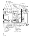
現在公表されているEUV露光装置を図1および図11〜図13を用いて説明する。図において、1は光源の発光点となる光源材料をガス化、液化または噴霧ガス化させたポイントに向けてレーザー光を照射して、光源材料原子をプラズマ励起することにより発光させるための励起レーザーで、YAG固体レーザー等を用いる。
A currently disclosed EUV exposure apparatus will be described with reference to FIGS. 1 and 11 to 13. In the figure,
2は露光用光源の光源発光部で、内部は真空に維持された構造を持ち、2Aは露光用光源の発光ポイント(以下、光源という)である。2Cは光源ミラーで、光源2Aからの全球面光を発光方向に揃え集光反射するために、光源2Aを中心に半球面状のミラーとして配置される。光源2Aのポイントには、発光元素として液化Xe、液化Xe噴霧体またはXeガスを不図示のノズルにより噴出させ、かつ、励起レーザー1からの光が照射される。
3は露光装置全体を格納する真空チャンバーで、真空ポンプ4により真空状態を維持することが可能である。5は光源発光部2からの露光光を導入して成形する露光光導入部で、ミラー5A〜5Dにより構成され、露光光を均質化し、かつ整形する。
6はレチクルステージで、レチクルステージ6上の可動部には、露光パターンの反射原版である原版6Aが搭載されている。7は原版6Aから反射した露光パターンを縮小投影する縮小投影ミラー光学系であり、原版6Aにより反射された露光パターンをミラー7A〜7Eに順次投影反射し最終的に規定の縮小倍率比でウエハ8A上に縮小投影する。8はウエハステージで、原版6Aにより反射縮小投影されたパターンを露光するSi基板であるウエハ8Aを、所定の露光位置に位置決めするために、XYZ方向、XY軸回りのチルト、Z軸回りの回転方向の6軸駆動可能に位置決め制御される。 Reference numeral 6 denotes a reticle stage, and a movable part on the reticle stage 6 is mounted with an original 6A which is a reflection original of an exposure pattern. Reference numeral 7 denotes a reduction projection mirror optical system for reducing and projecting the exposure pattern reflected from the original 6A. The exposure pattern reflected by the original 6A is sequentially projected and reflected on the mirrors 7A to 7E, and finally the wafer 8A at a specified reduction magnification ratio. Reduce the projection up. Reference numeral 8 denotes a wafer stage. In order to position a wafer 8A, which is a Si substrate for exposing a pattern projected by reflection reduction by the original 6A, at a predetermined exposure position, tilt about the XYZ direction, tilt about the XY axis, and rotation about the Z axis. Positioning is controlled so as to be capable of driving in six directions.
9はレチクルステージ支持体で、レチクルステージ6を装置設置床に対して支持する。10は投影系支持体で、縮小投影ミラー光学系7を装置設置床に対して支持する。11はウエハステージ支持体で、ウエハステージ8を装置設置床に対して支持する。以上のレチクルステージ支持体9と投影系支持体10とウエハステージ支持体11により分離独立して支持された、レチクルステージ6と縮小投影ミラー光学系7間、および縮小投影ミラー光学系7とウエハステージ8間は、相対位置を位置計測し所定の相対位置に連続して維持制御する手段(不図示)が設けられている。
また、レチクルステージ支持体9と投影系支持体10とウエハステージ支持体11には、装置設置床からの振動を絶縁するマウント(不図示)が設けられている。
A reticle stage support 9 supports the reticle stage 6 against the apparatus installation floor. Reference numeral 10 denotes a projection system support, which supports the reduction projection mirror optical system 7 with respect to the apparatus installation floor. A wafer stage support 11 supports the wafer stage 8 against the apparatus installation floor. Between the reticle stage 6 and the reduction projection mirror optical system 7, and between the reduction projection mirror optical system 7 and the wafer stage, which are separately and independently supported by the reticle stage support 9, the projection system support 10 and the wafer stage support 11. Between 8, there is provided means (not shown) for measuring the relative position and maintaining and controlling the relative position continuously.
The reticle stage support 9, projection system support 10, and wafer stage support 11 are provided with mounts (not shown) that insulate vibrations from the apparatus installation floor.
12は装置外部から一旦装置内部に原版6Aであるレチクルを保管するレチクルストッカーで、保管容器に異なるパターンおよび異なる露光条件に合わせたレチクルが密閉状態で保管されている。13はレチクルストッカー12から使用するレチクルを選択して搬送するレチクルチェンジャーである。14はXYZおよびZ軸周りに回転可能な回転ハンドから成るレチクルアライメントユニットで、レチクルチェンジャー13から原版6Aを受け取って180度回転することにより、レチクルステージ6端部に設けられたレチクルアライメントスコープ15部分に搬送し、縮小投影ミラー光学系7基準に設けられたアライメントマーク15A(図11参照)に対して原版6A上をXYZ軸回転方向に微動してアライメントする。アライメントを終了した原版6Aはレチクルステージ6上にチャッキングされる。 Reference numeral 12 denotes a reticle stocker that temporarily stores a reticle, which is an original 6A, from the outside of the apparatus, and the reticles having different patterns and different exposure conditions are stored in a sealed state in a storage container. A reticle changer 13 selects and transports a reticle to be used from the reticle stocker 12. 14 is a reticle alignment unit composed of a rotating hand that can rotate about XYZ and Z axes. The reticle alignment unit 15 is provided at the end of the reticle stage 6 by receiving the original 6A from the reticle changer 13 and rotating 180 degrees. Then, the original 6A is finely moved in the XYZ-axis rotation direction with respect to the alignment mark 15A (see FIG. 11) provided on the basis of the reduction projection mirror optical system 7 for alignment. The original 6A after alignment is chucked on the reticle stage 6.
16は装置外部から一旦装置内部にウエハ8Aを保管するウエハストッカーで、保管容器に複数枚のウエハが保管されている。17はウエハ搬送ロボットで、ウエハストッカー16から露光処理するウエハ8Aを選定し、ウエハメカプリアライメント温調器18に運ぶ。ウエハメカプリアライメント温調器18では、ウエハの回転方向の送り込み粗調整を行うと同時に、ウエハ温度を露光装置内部温調温度に合わせ込む。19はウエハ送り込みハンドで、ウエハメカプリアライメント温調器18にてアライメントと温調されたウエハ8Aをウエハステージ8に送り込む。 A wafer stocker 16 temporarily stores the wafer 8A inside the apparatus from the outside of the apparatus, and a plurality of wafers are stored in a storage container. A wafer transfer robot 17 selects the wafer 8A to be exposed from the wafer stocker 16 and carries it to the wafer mechanical pre-alignment temperature controller 18. The wafer mechanical pre-alignment temperature controller 18 adjusts the wafer rotation in the rotational direction and simultaneously adjusts the wafer temperature to the exposure apparatus internal temperature adjustment temperature. Reference numeral 19 denotes a wafer feeding hand, which feeds the wafer 8 A, which has been aligned and temperature-controlled by the wafer mechanical pre-alignment temperature controller 18, to the wafer stage 8.
20および21はゲートバルブで、装置外部からレチクルおよびウエハを挿入するゲート開閉機構である。22も同じくゲートバルブで、装置内部でウエハストッカー16およびウエハメカプリアライメント温調器18の空間と露光空間とを隔壁で分離し、ウエハ8Aを搬入搬出するときのみ開閉する。このように、隔壁で分離することによりウエハ8Aの装置外部との搬入搬出の際に、一旦大気開放される容積を最小限にして、速やかに真空平衡状態にすることを可能にしている。 Reference numerals 20 and 21 denote gate valves, which are gate opening / closing mechanisms for inserting a reticle and wafer from the outside of the apparatus. 22 is also a gate valve, and the space of the wafer stocker 16 and the wafer mechanical pre-alignment temperature controller 18 and the exposure space are separated by a partition inside the apparatus, and is opened and closed only when the wafer 8A is carried in and out. As described above, the separation by the partition wall makes it possible to minimize the volume once released to the atmosphere when the wafer 8A is carried into and out of the apparatus, and to quickly achieve a vacuum equilibrium state.
図11および図12において、6Bはレチクルチャックスライダー、6Cはレチクル駆動手段、6Fは静電チャック電極、14Aはレチクルアライメントハンド、14Bはレチクルアライメント静電チャック、37は原版アライメント制御回路である。
ところで、上記の露光装置では、非露光時から露光動作に移行した際に光源発光部2からの露光光を集光する光源ミラー2C、集光された露光光を導入成形する露光光導入部のミラー5A〜5D、および原版6Aから反射した露光パターンを縮小投影する縮小投影ミラー光学系のミラー7A〜7Eは、Mo−Siの多層膜が蒸着あるいはスパッタにより形成され、個々の反射面で光源2Aからの露光光を反射する。その際、一面あたりの反射率は凡そ70%程度で、残りはミラー母材に吸収され熱に変換される。
By the way, in the above-described exposure apparatus, the light source mirror 2C that collects the exposure light from the light source
図13(1)は、投影系ミラーDおよびE(図1の7Dおよび7E)の温度変化の一例を示す。非露光時の投影系ミラー温度T1に対して、露光を開始した際に徐々にミラー温度が上昇し、それぞれ温度T4および温度T3まで上昇し安定化する。ここで、露光光反射エリアでは温度が上昇し、結果として熱膨張係数の極めて小さいミラー材料を使用してもミラー周辺部では反射面の変位が発生し、結果として、1nm以下程度と、極めて厳しいミラー面形状精度が要求される投影系ミラー7A〜7E、照明系ミラー5A〜5Dおよび光源ミラー2Cの精度を補償出来なくなる。
このようにミラー面精度が悪化すると、投影系の場合ウエハへの結像性能の悪化および照度低下を招く。さらに照明系の場合マスクへの目標照度低下および照度ムラ悪化を招き、光源ミラーの場合は光源の集光不良等照度悪化を招く結果となる。これらは、総じて露光装置の露光精度およびスループット等の基本性能の劣化につながる
FIG. 13 (1) shows an example of the temperature change of the projection system mirrors D and E (7D and 7E in FIG. 1). With respect to the projection system mirror temperature T1 at the time of non-exposure, the mirror temperature gradually rises when exposure is started, and rises and stabilizes at temperatures T4 and T3, respectively. Here, in the exposure light reflection area, the temperature rises. As a result, even if a mirror material having a very small thermal expansion coefficient is used, the reflection surface is displaced in the periphery of the mirror, and as a result, it is extremely severe, about 1 nm or less. The accuracy of the projection system mirrors 7A to 7E, the illumination system mirrors 5A to 5D and the light source mirror 2C that require mirror surface shape accuracy cannot be compensated.
When the mirror surface accuracy deteriorates in this way, in the case of a projection system, the imaging performance on the wafer deteriorates and the illuminance decreases. Furthermore, in the case of an illumination system, the target illuminance is reduced and the illuminance unevenness is deteriorated. In the case of a light source mirror, the illuminance is deteriorated such as a light source is not condensing. These generally lead to deterioration of basic performance such as exposure accuracy and throughput of the exposure apparatus.
また、上記反射ミラーと同じく原版に関しても、同様の問題が発生する。図13(2)は、原版の温度変化の一例を示す。非露光時の原版温度T1に対して、露光を開始した際に徐々に原版面温度が上昇し、温度T2まで上昇し安定化する。ここで、原版のパターン露光光反射エリアでは温度が上昇し、結果として熱膨張係数の極めて小さい原版ミラー材料を使用しても原版パターン反射面の変位が発生し、結果として、原版パターン歪およびパターン倍率誤差が発生し解像精度を劣化させる問題が発生していた。
本発明は、上述の従来例における問題点を解消することを課題とする。
Similar problems occur with the original plate as with the reflection mirror. FIG. 13 (2) shows an example of the temperature change of the original plate. With respect to the original plate temperature T1 at the time of non-exposure, when the exposure is started, the original plate surface temperature gradually rises to the temperature T2 and stabilizes. Here, the temperature rises in the pattern exposure light reflection area of the original, and as a result, even if an original mirror material having a very small coefficient of thermal expansion is used, displacement of the original pattern reflecting surface occurs, resulting in the original pattern distortion and pattern. There was a problem that a magnification error occurred and the resolution accuracy deteriorated.
An object of the present invention is to solve the problems in the above-described conventional example.
上記の課題を解決するため、本発明に係る第1の露光装置は、光源からの露光光により原版を照明する照明光学系と、前記照明光学系により照明された前記原版のパターンを基板に投影する投影光学系とを有する露光装置において、前記投影光学系の光学素子を加熱する輻射部材と、前記輻射部材を用いて前記光学素子の温度を制御する制御手段と、前記投影光学系の収差又は光軸を計測する計測手段とを有し、前記制御手段は、前記光学素子が前記露光光により露光されていないときに、露光時の定常状態の温度と同じ温度になるように、前記光学素子へに単位時間あたりの露光時入射光量予測から前記光学素子の温度上昇予測値を算出して前記輻射部材の温度を設定し、前記光学素子の温度が露光時の温度にならない場合に前記光学素子の過去の露光履歴及び温度履歴に基づいて前記輻射部材の設定温度を補正して前記光学素子の温度を制御し、前記計測手段は該制御された前記光学素子を含む前記投影光学系の収差又は光軸を計測することを特徴とする。ここで、光学素子は、反射ミラーやレンズ等である。 In order to solve the above problems, a first exposure apparatus according to the present invention projects an illumination optical system that illuminates an original with exposure light from a light source, and a pattern of the original that is illuminated by the illumination optical system onto a substrate. In the exposure apparatus having the projection optical system, a radiation member that heats the optical element of the projection optical system, a control unit that controls the temperature of the optical element using the radiation member, an aberration of the projection optical system, or and a measuring means for measuring the optical axis, wherein, when the optical element is not exposed by the exposure light, to be the same temperature as the temperature of the steady state at the time of exposure, the optical element by calculating the temperature rise estimated value of the optical element from the exposure time of an incident light amount predicted per unit time f to set the temperature of the radiation member, the optical element when the temperature of the optical element is not a temperature at the time of exposure The set temperature of the radiation member on the basis of past exposure history and temperature history by correcting controlling the temperature of said optical element, said measuring means aberration or light of the projection optical system including said optical element said control It is characterized by measuring an axis. Here, the optical element is a reflection mirror, a lens, or the like.
本発明に係る第2の露光装置は、前記第1の露光装置において、投影光学系の光学素子を駆動する駆動手段と、前記光学素子の位置を計測する位置計測手段と、前記投影光学系の収差又は光軸を計測する計測手段の計測結果に基づいて前記光学素子の駆動量を算出する駆動量算出手段とを有し、前記駆動量算出手段により算出された駆動量及び前記位置計測手段の情報に応じて、前記駆動手段が前記光学素子を駆動して、前記投影光学系の収差又は光軸を調整することを特徴とする。 According to a second exposure apparatus of the present invention, in the first exposure apparatus, a driving unit that drives an optical element of a projection optical system, a position measurement unit that measures the position of the optical element, and a projection optical system Drive amount calculation means for calculating the drive amount of the optical element based on the measurement result of the measurement means for measuring aberration or the optical axis, and the drive amount calculated by the drive amount calculation means and the position measurement means depending on the information, the drive means by driving the optical element, characterized that you adjust the aberrations or optical axis of the projection optical system.
本発明に係る計測方法は、光源からの露光光により照明される原版のパターンを、基板に投影する投影光学系の収差又は光軸を計測する計測方法において、輻射部材が前記投影光学系の光学素子を加熱するステップと、前記輻射部材を用いて前記光学素子の温度を制御する制御ステップと、前記投影光学系の収差又は光軸を計測する計測ステップとを備え、前記制御ステップにおいて、前記光学素子が前記露光光により露光されていないときに、露光時の定常状態の温度と同じ温度になるように、前記光学素子へに単位時間あたりの露光時入射光量予測から前記光学素子の温度上昇予測値を算出して前記輻射部材の温度を設定し、前記光学素子の温度が露光時の温度にならない場合に前記光学素子の過去の露光履歴及び温度履歴に基づいて前記輻射部材の設定温度を補正して前記光学素子の温度を制御し、前記計測ステップにおいて、該制御された前記光学素子を含む前記投影光学系の収差又は光軸を計測することを特徴とする。 The measurement method according to the present invention is a measurement method for measuring an aberration or an optical axis of a projection optical system that projects an original pattern illuminated by exposure light from a light source onto a substrate, wherein the radiation member is an optical element of the projection optical system. A heating step of the element, a control step of controlling the temperature of the optical element using the radiation member, and a measurement step of measuring an aberration or an optical axis of the projection optical system. Predicting the temperature rise of the optical element from the prediction of the amount of incident light per unit time to the optical element so that the temperature is the same as the steady state temperature at the time of exposure when the element is not exposed by the exposure light to calculate the value to set the temperature of the radiating member, before the temperature of the optical element based on past exposure history and temperature history of the optical element when not in temperature during exposure The set temperature of the radiating member is corrected by controlling the temperature of the optical element, in the measuring step, characterized by measuring the aberrations or optical axis of the projection optical system including said optical element said control.
本発明によれば、露光開始時の光学素子あるいは原版面の過渡的な温度変化を無くし、光学素子あるいは原版面パターンの歪発生を無くし、露光開始時の光学素子の温度変化に伴う収差悪化および原版のパターン歪発生を防ぎ、高精度の露光装置を実現することができる。また、照明光学系や投影光学系の光軸調整時あるいは各光学素子の収差調整時に、光学素子を例えば輻射温調ヒーターでプリヒート温調することで、露光動作時状態での光軸調整あるいは収差調整が可能になり、露光時の収差発生および変化の少ない露光装置を実現する効果がある。 According to the present invention, the transient temperature change of the optical element or the original plate surface at the start of exposure is eliminated, the generation of distortion of the optical element or the original plate surface pattern is eliminated, the aberration deterioration accompanying the temperature change of the optical element at the start of exposure and Generation of pattern distortion in the original can be prevented, and a highly accurate exposure apparatus can be realized. Also, when adjusting the optical axis of the illumination optical system or projection optical system, or adjusting the aberration of each optical element, the optical element is preheated with, for example, a radiation temperature adjusting heater, so that the optical axis is adjusted or aberrations in the exposure operation state. Adjustment is possible, and there is an effect of realizing an exposure apparatus with little occurrence and change of aberration during exposure.
以下、本発明の実施態様を列挙する。
[実施態様1]原版面に描かれたパターンを投影光学系を介して基板に投影し、該投影光学系に対し原版と基板の両方、もしくは基板のみをステージ装置により相対的に移動させることにより、原版のパターンを基板に繰り返し露光する露光装置において、投影光学系あるいは投影光学系に露光光を供給する照明光学系あるいは露光光源部に設けられた反射ミラーに対し離間した位置に輻射温調手段を設け、非露光時と露光時の該反射ミラー温度変化に略同期して輻射温調手段の温度を可変とすることを特徴とする露光装置。
[実施態様2]原版面に描かれたパターンを投影光学系を介して基板に投影し、該投影光学系に対し原版と基板の両方、もしくは基板のみをステージ装置により相対的に移動させることにより、原版のパターンを基板に繰り返し露光する露光装置において、原版面から離間した位置に輻射温調手段を設け、非露光時と露光時の該原版温度変化に略同期して、輻射温調手段の温度を可変とすることを特徴とする露光装置。
[実施態様3]実施態様1または2に示す露光装置で、該輻射温調手段の設定温度を、露光量あるいは露光画角あるいは露光時間あるいはその他の該反射ミラーまたは原版の温度を変える露光条件変数により、可変としたことを特徴とする露光装置。
[実施態様4]実施態様2に示す露光装置で、原版ステージの露光光導入部位以外の原版から離間した位置に該輻射温調手段を設け、非露光時に原版ステージにより原版を該輻射手段に対向した位置に移動させ、輻射温調することを特徴とする露光装置。
[実施態様5]実施態様4に示す露光装置で、非露光時に原版を該輻射手段に対向した位置に移動させ温調する際に、原版ステージを該輻射温調手段に対して略原版面内で移動動作させることを特徴とする露光装置。
The embodiments of the present invention are listed below.
[Embodiment 1] By projecting a pattern drawn on an original surface onto a substrate via a projection optical system, and moving both the original plate and the substrate or only the substrate relative to the projection optical system by a stage device. In an exposure apparatus that repeatedly exposes a pattern of an original on a substrate, a radiation temperature adjusting means at a position separated from a projection optical system or an illumination optical system that supplies exposure light to the projection optical system or a reflection mirror provided in an exposure light source unit An exposure apparatus characterized in that the temperature of the radiation temperature adjusting means is variable substantially in synchronization with the temperature change of the reflecting mirror during non-exposure and during exposure.
[Embodiment 2] By projecting a pattern drawn on an original plate surface onto a substrate via a projection optical system, and moving both the original plate and the substrate or only the substrate relative to the projection optical system by a stage device. In the exposure apparatus that repeatedly exposes the pattern of the original on the substrate, a radiation temperature adjusting means is provided at a position spaced from the original surface, and the radiation temperature adjusting means is substantially synchronized with the original temperature change during non-exposure and exposure. An exposure apparatus characterized in that the temperature is variable.
[Embodiment 3] In the exposure apparatus shown in
[Embodiment 4] In the exposure apparatus shown in
[Embodiment 5] In the exposure apparatus shown in Embodiment 4, when the temperature of the original plate is moved to a position opposed to the radiation means during non-exposure and the temperature is adjusted, the original stage is substantially within the original plate surface with respect to the radiation temperature adjustment means. An exposure apparatus characterized in that the exposure apparatus is moved and operated.
[実施態様6]原版面に描かれたパターンを投影光学系を介して基板に投影し、該投影光学系に対し原版と基板の両方、もしくは基板のみをステージ装置により相対的に移動させることにより、原版のパターンを基板に繰り返し露光する露光装置において、投影光学系あるいは投影光学系に露光光を供給する照明光学系あるいは露光光源部に設けられた反射ミラーに対して離間した輻射温調手段と、投影光学系あるいは投影光学系に露光光を供給する照明光学系あるいは露光光源部に設けられた反射ミラーの光軸計測手段あるいは波面収差計測手段を設け、非露光時の該光軸調整あるいは該波面収差調整を行う際に、該反射ミラーに対して該輻射温調手段による温調をすることを特徴とする露光装置。
[実施態様7]実施態様6に記載の露光装置で、該輻射温調手段と該光軸計測手段あるいは該波面収差計測手段の計測値から、反射ミラー位置補正駆動手段あるいは反射ミラー形状補正手段の補正駆動量を算出制御することを特徴とする露光装置。
[Embodiment 6] By projecting a pattern drawn on the original surface onto a substrate via a projection optical system, and moving both the original and substrate, or only the substrate relative to the projection optical system by a stage device. In an exposure apparatus that repeatedly exposes a pattern of an original on a substrate, radiation temperature control means spaced from a projection optical system or an illumination optical system that supplies exposure light to the projection optical system or a reflection mirror provided in an exposure light source unit; A projection optical system, an illumination optical system for supplying exposure light to the projection optical system, or a reflection mirror optical axis measurement means or wavefront aberration measurement means provided in the exposure light source section, to adjust the optical axis during non-exposure or An exposure apparatus characterized in that when the wavefront aberration is adjusted, the temperature of the reflection mirror is adjusted by the radiation temperature adjusting means.
[Embodiment 7] In the exposure apparatus according to Embodiment 6, from the measured values of the radiation temperature adjusting means and the optical axis measuring means or the wavefront aberration measuring means, the reflecting mirror position correcting driving means or the reflecting mirror shape correcting means An exposure apparatus characterized by calculating and controlling a correction driving amount.
上記の実施態様によれば、露光光源から被露光基板に至る露光光の光路上に位置する反射ミラーあるいは原版への露光光の非入射時に、反射ミラーあるいは原版面を、例えば輻射温調ヒーターでプリヒート温調することで、露光開始時の反射ミラーあるいは原版面の温度変化を抑制し、反射ミラーあるいは原版面パターンの歪発生を抑制し、露光開始時のミラー温度変化に伴う収差悪化および原版のパターン歪発生を抑制することができる。
また、投影光学系の光軸調整時あるいは反射ミラー収差調整時に、反射ミラーを例えば輻射温調ヒーターでプリヒート温調することで、露光動作時と均等な状態での光軸調整あるいは収差調整を可能とし、露光開始時のミラー温度変化に伴う収差悪化および原版のパターン歪発生を抑制することができる。
According to the above embodiment, when the exposure light is not incident on the reflection mirror or the original plate located on the optical path of the exposure light from the exposure light source to the substrate to be exposed, the reflection mirror or the original surface is, for example, a radiation temperature control heater. By adjusting the preheat temperature, the temperature change of the reflection mirror or the original plate surface at the start of exposure is suppressed, the distortion of the reflection mirror or the original plate surface pattern is suppressed, the aberration deterioration due to the mirror temperature change at the start of exposure and the original plate Generation of pattern distortion can be suppressed.
In addition, when adjusting the optical axis of the projection optical system or adjusting the reflective mirror aberration, the optical axis or aberration can be adjusted in the same state as the exposure operation by preheating the reflective mirror with a radiation temperature control heater, for example. As a result, it is possible to suppress aberration deterioration and generation of pattern distortion of the original plate due to mirror temperature change at the start of exposure.
以下、本発明の実施例を図面を用いて説明する。
[第1の実施例]
図1は、本発明の一実施例に係るEUV露光装置の全体構成を示す概略図である。この露光装置は、上記した従来例に対し、図2に示すように、投影系ミラー7Cに対して離間した位置で輻射温調するミラー温調手段23、投影系ミラー7Eに対して離間した位置で輻射温調するミラー温調手段24、ミラー7Cの温度を計測するミラー温度検出手段25、ミラー7Eの温度を計測するミラー温度検出手段26およびミラー温度検出手段25、26からの温度計測値に従いミラー温調手段23、24の設定温度を決める温度制御手段を設けたものである。他の部分は上記従来例と同様に構成される。以下、主に上記従来例と異なる部分について説明する。
Embodiments of the present invention will be described below with reference to the drawings.
[First embodiment]
FIG. 1 is a schematic diagram showing the overall configuration of an EUV exposure apparatus according to an embodiment of the present invention. As shown in FIG. 2, this exposure apparatus has a mirror temperature adjusting means 23 for adjusting the radiation temperature at a position separated from the projection system mirror 7C and a position separated from the projection system mirror 7E. In accordance with the temperature measurement values from the mirror temperature adjusting means 24 for adjusting the radiation temperature, the mirror temperature detecting means 25 for measuring the temperature of the mirror 7C, the mirror temperature detecting means 26 for measuring the temperature of the mirror 7E, and the mirror temperature detecting means 25, 26. Temperature control means for determining the set temperature of the mirror temperature adjusting means 23, 24 is provided. Other parts are configured in the same manner as in the conventional example. In the following, differences from the conventional example will be mainly described.
図2(1)を参照して、露光装置の非露光時は、露光時にミラー7Cおよび7Eにそれぞれ入射する露光熱量を予測し、そのときの各ミラーの上昇温度に合わせてミラー温調手段23および24により、ミラー7Cおよび7Eを反射面側から輻射温調プリヒートする。その際、ミラー温度検知手段25および26から、各ミラー自身の温度を検出し、温度制御手段27により、ミラー温調手段23および24の温度制御を行う。 Referring to FIG. 2A, when the exposure apparatus is not exposed, the amount of exposure heat incident on each of mirrors 7C and 7E during exposure is predicted, and mirror temperature adjusting means 23 is adjusted in accordance with the rising temperature of each mirror at that time. And 24, the mirrors 7C and 7E are preheated from the reflecting surface side by adjusting the radiation temperature. At that time, the temperature of each mirror itself is detected from the mirror temperature detecting means 25 and 26, and the temperature control means 27 controls the temperature of the mirror temperature adjusting means 23 and 24.
図2(2)に温度制御の状態を示す。ここで、横軸は非露光状態から露光状態に移行する経過時間を、縦軸は各部位の温度を示す。
それぞれのミラーへの単位時間あたりの露光時入射光量予測から、各ミラーの温度上昇予測値を算出し、非露光時に、ミラー温調手段23および24の設定温度を、T7およびT6に設定する。このとき、各ミラーの温度は、それぞれミラー温度検知手段25により温度T5、ミラー温度検出手段26により温度T4で示される。ミラー7Cおよび7Eの非露光時の温度が露光時の温度T5およびT4とならないときは、ミラー温度検知手段25および26の計測値温度に基づいて、ミラー温調手段23および24の設定温度を、負帰還制御する。または、過去の露光履歴と温度履歴に基づいてミラー温調手段23および24の設定温度をT7およびT6から補正してもよい。
FIG. 2 (2) shows the temperature control state. Here, the horizontal axis represents the elapsed time from the non-exposure state to the exposure state, and the vertical axis represents the temperature of each part.
The predicted temperature rise value of each mirror is calculated from the prediction of the amount of incident light per unit time for each mirror, and the set temperatures of the mirror temperature adjusting means 23 and 24 are set to T7 and T6 during non-exposure. At this time, the temperature of each mirror is indicated by a temperature T5 by the mirror temperature detecting means 25 and a temperature T4 by the mirror temperature detecting means 26, respectively. When the non-exposure temperatures of the mirrors 7C and 7E do not become the exposure temperatures T5 and T4, the set temperatures of the mirror temperature adjusting means 23 and 24 are set based on the measured temperature of the mirror temperature detecting means 25 and 26. Negative feedback control. Alternatively, the set temperatures of the mirror temperature adjusting means 23 and 24 may be corrected from T7 and T6 based on the past exposure history and temperature history.
一方、露光時には、光源発光部2からの露光光を導入成形する露光光導入部のミラー5A〜5Dおよび原版6Aから反射した露光パターンを縮小投影する縮小投影ミラー光学系において、ミラー7A〜7EのMo−Siの多層膜が蒸着あるいはスパッタにより形成された個々の反射面で光源2Aからの露光光を反射する。その際、ミラー1面当たりの反射率は凡そ70%程度で残りはミラー母材に吸収され熱に変換され、露光光反射エリアでは温度が上昇する。そこで、本実施例では、非露光時と露光時の温度差が発生しないよう、露光開始と同時にミラー温調手段23および24の温度をT7およびT6から徐々に下降させ、露光時の定常状態ではミラー温調手段23および24の温度をミラー温度より下降させることにより、露光光の入射光量による温度上昇とバランスさせ、結果としてミラー温度を一定温度に維持する。
On the other hand, at the time of exposure, in the reduction projection mirror optical system for reducing and projecting the exposure pattern reflected from the original light 6A and the mirrors 5A to 5D of the exposure light introduction part for introducing and shaping the exposure light from the light source light emitting
本実施例では、このように、非露光時の反射ミラーの温度を露光時と実質同一とすることにより、露光開始時の反射ミラーの過渡的な温度変化を無くし、反射ミラーの歪発生を無くし、露光開始時のミラー温度変化に伴う収差悪化を防ぎ、高精度の露光装置を実現することができる。なお、本実施例は、光源2からウエハ8Aに至るいずれの反射ミラー2C、5A〜5Dおよび7A〜7Eにも適用可能であり、同様に反射ミラーの歪発生を防止することができる。また、反射ミラーのみでなく、原版(レチクル)6Aにも適用可能である。この場合、露光開始時の原版の過渡的な温度変化を無くし、原版の歪発生を無くし、露光開始時の原版温度変化に伴う原版のパターン歪発生を防ぎ、高精度の露光装置を実現することができる。
In this embodiment, the temperature of the reflecting mirror at the time of non-exposure is made substantially the same as that at the time of exposure, thereby eliminating a transient temperature change of the reflecting mirror at the start of exposure and eliminating distortion of the reflecting mirror. Thus, it is possible to prevent the aberration from being deteriorated due to the change in the mirror temperature at the start of exposure and to realize a highly accurate exposure apparatus. This embodiment can be applied to any of the reflection mirrors 2C, 5A to 5D and 7A to 7E from the
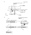
[第2の実施例]
第2の実施例を図3に示す。ここでは、露光装置本体上で、縮小投影ミラー光学系7の光軸調整あるいは反射ミラーの収差調整を行う際に、各ミラーの輻射温調を行う例を示す。図3において、ミラー7Aと7Dに対しては、ミラー温調手段28が離間して設けられている。ミラー7Bに対しては、ミラー温調手段37Bが離間して設けられている。ミラー7Cに対しては、ミラー温調手段23が離間して設けられている。ミラー7Eに対してはミラー温調手段24が離間して設けられている。
また、各ミラー7A〜7Eには、それぞれミラー温度検知手段29A、37A、25、29Dおよび26が設けられ、各ミラー温度検知手段からの温度計測値は、温度制御手段27に集められる。
[Second Embodiment]
A second embodiment is shown in FIG. Here, an example is shown in which the radiation temperature of each mirror is adjusted when adjusting the optical axis of the reduction projection mirror optical system 7 or adjusting the aberration of the reflecting mirror on the exposure apparatus body. In FIG. 3, the mirror temperature adjusting means 28 is provided apart from the mirrors 7A and 7D. A mirror temperature adjusting means 37B is provided apart from the mirror 7B. The mirror temperature adjusting means 23 is provided apart from the mirror 7C. The mirror temperature adjusting means 24 is provided apart from the mirror 7E.
Each of the mirrors 7A to 7E is provided with mirror temperature detection means 29A, 37A, 25, 29D and 26, and the temperature measurement values from the mirror temperature detection means are collected in the temperature control means 27.
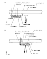
縮小投影ミラー光学系7の光軸および収差を計測する手段として、レチクルステージ6の背面から波面計測光供給ファイバー30により導かれた計測光が、波面計測光源出射口31から出射される。波面計測光源出射口31から出射された光は、各ミラー7A〜7Eに入反射しながら、最終的にウエハステージ8上に設けられた光軸&波面計測光センサー32にて受光検出される。
33は光軸&波面計測受光センサー32からの信号から光軸および波面収差を演算する波面計測値演算回路、34は波面計測値演算回路33にて算出された光軸ずれおよび収差残差からミラー補正駆動量を演算するミラー補正駆動テーブル演算回路、35はミラー補正駆動テーブル演算回路34からの補正駆動信号からミラーに対して補正駆動するミラー補正駆動手段で、ミラー支持アクチュエーター(不図示)をXYZ方向に微動させることにより、ミラー面の面内並進シフト方向の補正ならびに微小変位および回転軸倒れの補正を可能にする。36はミラー補正駆動量を検出するミラー計測手段である。
As means for measuring the optical axis and aberration of the reduction projection mirror optical system 7, the measurement light guided by the wavefront measurement light supply fiber 30 from the back surface of the reticle stage 6 is emitted from the wavefront measurement light source emission port 31. The light emitted from the wavefront measurement light source exit 31 is received and detected by the optical axis & wavefront measurement optical sensor 32 finally provided on the wafer stage 8 while being reflected by the mirrors 7A to 7E.
33 is a wavefront measurement value calculation circuit for calculating the optical axis and wavefront aberration from the signal from the optical axis & wavefront measurement light receiving sensor 32, and 34 is a mirror based on the optical axis deviation and aberration residual calculated by the wavefront measurement value calculation circuit 33. A mirror correction drive table calculation circuit for calculating the correction drive amount, and 35 is a mirror correction drive means for correcting and driving the mirror from the correction drive signal from the mirror correction drive table calculation circuit 34. The mirror support actuator (not shown) is XYZ. By finely moving in the direction, correction of the in-plane translational shift direction of the mirror surface and correction of minute displacement and rotation axis tilt are possible. Reference numeral 36 denotes mirror measurement means for detecting the mirror correction drive amount.
以上の構成で、縮小投影ミラー光学系7の光軸および収差を調整する際には、温調制御手段27に集められたミラー温度検知手段29A、37A、25、29Dおよび26からの計測値と、各ミラーの露光時の設定温度から、各ミラーのミラー温調手段の設定温度を算出し、ミラー温調手段23、24、28、38の温度を制御することにより、露光時と同等状態の各ミラー温度に制御可能となる。各ミラー温度が、露光時と同等温度になったことが、温度制御手段27により確認された後、レチクルステージ6のレチクルチャックスライダー6Bが退避した状態で、図示のように波面計測計計測光源供給ファイバー30から供給された計測光を、波面評価光源光を出射する波面計測計計測光源出射口31から出射して、計測光が投影系ミラー反射面の全面で通しで反射し、図に示すようにウエハステージ8可動部に搭載された光軸&波面計測受光センサー32にて、反射ミラー全面での投影系の光軸誤差量および光学波面収差量が計測される。光軸&波面計測受光センサー32にて計測された光軸&波面計測値は、波面計測値演算回路33にて、光軸および波面収差補正量が算出される。この光軸および波面収差補正量を元にミラー補正駆動テーブル演算回路34にて、ミラー7A〜7Eの各補正駆動方向および駆動量および力印加量が算出され、ミラー補正駆動制御手段35へ目標値として伝達される。同時にミラー7A〜7Eの各位置を計測する手段(不図示)からの情報をミラー計測手段36にまとめることによりミラー間の相対位置が計測される。 With the above configuration, when adjusting the optical axis and aberration of the reduction projection mirror optical system 7, the measured values from the mirror temperature detection means 29A, 37A, 25, 29D and 26 collected by the temperature control means 27 By calculating the set temperature of the mirror temperature adjusting means of each mirror from the set temperature at the time of exposure of each mirror and controlling the temperature of the mirror temperature adjusting means 23, 24, 28, 38, the state equivalent to that at the time of exposure is obtained. Each mirror temperature can be controlled. After confirming by the temperature control means 27 that the temperature of each mirror has become the same as that at the time of exposure, with the reticle chuck slider 6B of the reticle stage 6 retracted, a wavefront measuring instrument measuring light source is supplied as shown. The measurement light supplied from the fiber 30 is emitted from the wavefront measuring instrument measurement light source emission port 31 that emits the wavefront evaluation light source light, and the measurement light is reflected through the entire surface of the projection system mirror reflection surface, as shown in the figure. In addition, the optical axis & wavefront measurement light receiving sensor 32 mounted on the movable part of the wafer stage 8 measures the optical axis error amount and optical wavefront aberration amount of the projection system over the entire reflection mirror. Optical axis & wavefront measurement The optical axis & wavefront measurement value measured by the light receiving sensor 32 is calculated by the wavefront measurement value calculation circuit 33 for the optical axis and wavefront aberration correction amount. Based on the optical axis and wavefront aberration correction amounts, the mirror correction drive table calculation circuit 34 calculates the correction drive directions, drive amounts, and force application amounts of the mirrors 7A to 7E, and supplies the target values to the mirror correction drive control means 35. As transmitted. At the same time, the information from the means (not shown) for measuring the positions of the mirrors 7A to 7E is collected in the mirror measuring means 36, whereby the relative position between the mirrors is measured.
ミラー補正駆動手段35およびミラー計測手段36により、各ミラーを目標位置に駆動した後、再度光軸および波面計測確認を行い、光軸および波面収差が規格値を満たしていれば補正終了となり、光軸および波面収差が規格値を満たしていなければ、再度残留波面収差量を波面計測演算回路で算出して、上記補正を繰り返すことにより目標規格値に追い込む。
上記のように、各ミラー温度を露光時と同等状態で、光軸および収差調整を行うことにより、露光時の状態で安定した光軸および収差を満たすことができる。すなわち、本実施例によれば、投影光学系の光軸調整時あるいは反射ミラー収差調整時に、反射ミラーを輻射温調ヒーターでプリヒート温調することで、露光動作時状態での光軸調整あるいは収差調整が可能になり、露光時の収差発生および変化の少ない露光装置を実現する効果がある。
After each mirror is driven to the target position by the mirror correction driving means 35 and the mirror measuring means 36, the optical axis and wavefront measurement are confirmed again. If the optical axis and wavefront aberration satisfy the standard values, the correction is completed, If the axial and wavefront aberrations do not satisfy the standard value, the residual wavefront aberration amount is calculated again by the wavefront measurement calculation circuit, and the correction is repeated to drive the target standard value.
As described above, by adjusting the optical axis and aberration with each mirror temperature equivalent to that at the time of exposure, a stable optical axis and aberration can be satisfied in the state at the time of exposure. That is, according to the present embodiment, when adjusting the optical axis of the projection optical system or adjusting the reflection mirror aberration, the reflection mirror is preheated with the radiation temperature adjustment heater, thereby adjusting the optical axis or aberration in the exposure operation state. Adjustment is possible, and there is an effect of realizing an exposure apparatus with little occurrence and change of aberration during exposure.
[第3の実施例]
本発明の第3の実施例を図4〜図7に示す。上記第1および第2の実施例では、投影系ミラーの非露光時温調に関して本発明を実施したが、本発明は原版に対しても適用可能である。本実施例では、図4(1)に示すように、レチクルステージ6のレチクルアライメントスコープ15の設けられている方向の退避位置に対向する部分に離間して、温調輻射板38を設ける。
[Third embodiment]
A third embodiment of the present invention is shown in FIGS. In the first and second embodiments, the present invention has been implemented with respect to the non-exposure temperature control of the projection system mirror, but the present invention can also be applied to the original. In this embodiment, as shown in FIG. 4A, a temperature adjusting radiation plate 38 is provided apart from a portion of the reticle stage 6 that faces the retracted position in the direction in which the reticle alignment scope 15 is provided.
図4および図5にレチクル交換の流れを示す。
図4を参照して、原版(レチクル)6Aと原版(レチクル)6Dを交換する際、図4(1)に示すように、レチクルアライメントハンド14上に原版(レチクル)6Dが保持され、原版(レチクル)6Aを搭載したレチクルチャックスライダー6Bが交換位置に移動する。
レチクルアライメントハンド14Aは、レチクルアライメントユニット14により、図4(1)の状態から図4(2)に示すように、上方へ移動した後、原版(レチクル)6Aをレチクルチャックスライダー6Bのレチクルチャック6Eから受け渡され、下方へ退避後回転動作を行い、図4(3)に示すように、原版の交換作業が完了する。
4 and 5 show the flow of reticle replacement.
Referring to FIG. 4, when exchanging original plate (reticle) 6A and original plate (reticle) 6D, as shown in FIG. 4 (1), original plate (reticle) 6D is held on reticle alignment hand 14, and the original plate (reticle) The reticle chuck slider 6B carrying the reticle 6A moves to the replacement position.
The reticle alignment hand 14A is moved upward from the state of FIG. 4 (1) by the reticle alignment unit 14 as shown in FIG. 4 (2), and then the original (reticle) 6A is moved to the reticle chuck 6E of the reticle chuck slider 6B. Then, after the retreat downward, the rotating operation is performed, and as shown in FIG.
次に、原版(レチクル)のレチクルステージに対するアライメント作業の説明をする。
図5(1)に示すように、レチクルアライメントハンド14Aに設けられたレチクルアライメント静電チャック(不図示)により吸着搬送された、原版(レチクル)6Dのアライメント動作を行う。すなわち、原版(レチクル)6Dの位置誤差を、レチクルアライメントマーク15Aとの相対位置合わせ誤差からレチクルアライメントスコープ15で計測検出して、原版アライメント制御回路37により、レチクルアライメントユニット14が駆動制御され、レチクルアライメントハンド14AによりXY(面内方向)およびωZ(Z軸回転方向)にアライメント動作が行われることにより、原版(レチクル)6Dのアライメントが行われる。原版(レチクル)6Dのアライメントが終了した時点で、レチクルチャックスライダー6Bのレチクルチャック(静電チャック)6Eにより、原版(レチクル)6Dの裏面(上面)をクーロン力あるいはジョンソンラーベック力により吸着クランプする。
また、原版(レチクル)6Dがレチクルチャックスライダー6Bに吸着クランプされた状態で、原版(レチクル)6Dの温度を検知する手段として、レチクルチャックスライダー6B部にレチクル&レチクルチャックスライダー温度検出手段6G(図6(1)参照)が設けられている。
Next, an alignment operation for the reticle stage of the original (reticle) will be described.
As shown in FIG. 5A, an alignment operation of the original (reticle) 6D that is attracted and conveyed by a reticle alignment electrostatic chuck (not shown) provided in the reticle alignment hand 14A is performed. In other words, the position error of the original (reticle) 6D is measured and detected by the reticle alignment scope 15 from the relative alignment error with respect to the reticle alignment mark 15A, and the reticle alignment unit 14 is driven and controlled by the original alignment control circuit 37. An alignment operation is performed in the XY (in-plane direction) and ωZ (Z-axis rotation direction) by the alignment hand 14A, whereby the original (reticle) 6D is aligned. When the alignment of the original (reticle) 6D is completed, the back surface (upper surface) of the original (reticle) 6D is suction-clamped by Coulomb force or Johnson Rabeck force by the reticle chuck (electrostatic chuck) 6E of the reticle chuck slider 6B. .
In addition, as a means for detecting the temperature of the original (reticle) 6D in a state where the original (reticle) 6D is attracted and clamped to the reticle chuck slider 6B, the reticle & reticle chuck slider temperature detecting means 6G (see FIG. 6 (1)).
図6および図7を用いて温調輻射板38を用いた、原版(レチクル)6Dに対する非露光時のプリヒート動作を説明する。温調輻射板38は、図6(1)に示すように、露光光2Bの入射位置を退避した位置の原版(レチクル)6Dに対して対向離間した位置に設けられている。
原版(レチクル)6Dを温調輻射板38に対向する位置に移動させ、レチクルチャックスライダー6Bに設けられたレチクル&レチクルチャックスライダー温度検出手段6Gにて原版(レチクル)6Dの温度を計測し、その計測値をレチクル&レチクルチャックスライダー温度検知回路39に伝送して補正温度量を算出する。同時に露光制御手段41の有する、原版(レチクル)に入射する露光量情報から原版(レチクル)への入射熱量情報を予測し、両情報から非露光時の原版(レチクル)6Dの温調設定温度をレチクル輻射温調制御手段40にて決定し、レチクル輻射温調手段42にて温調輻射板38の温度を制御する。
温調輻射板38から原版(レチクル)6Dの露光光入射領域となる有効パターン領域への輻射温調を均一に行うために、レチクルチャックスライダー6Bを温調輻射板38に対して往復移動させる。
The preheating operation at the time of non-exposure to the original plate (reticle) 6D using the temperature control radiation plate 38 will be described with reference to FIGS. As shown in FIG. 6A, the temperature control radiation plate 38 is provided at a position facing and separating from the original (reticle) 6D at the position where the incident position of the exposure light 2B is retracted.
The original (reticle) 6D is moved to a position facing the temperature control radiation plate 38, and the temperature of the original (reticle) 6D is measured by the reticle & reticle chuck slider temperature detecting means 6G provided on the reticle chuck slider 6B. The measured value is transmitted to the reticle & reticle chuck slider
The reticle chuck slider 6B is reciprocated with respect to the temperature adjustment radiation plate 38 in order to uniformly adjust the radiation temperature from the temperature adjustment radiation plate 38 to the effective pattern area as the exposure light incident area of the original (reticle) 6D.
以上の非露光時の原版(レチクル)温調により、図7に示すように、非露光時の輻射温調板38を温度T9を設定温度としてプリヒートすることで、原版(レチクル)6Dの温度はT8の状態となっている。この状態から、露光を開始する時、輻射温調板38の設定温度を露光光による原版(レチクル)温度上昇に合わせて、下降させる。結果として、輻射温調板38からの熱量と露光光からの熱量の合計が、一定値となる制御をすることにより、露光開始後も原版(レチクル)6Dの温度は一定値T8を維持することが出来る。
結果として、原版(レチクル)の歪および形状変化が非露光時から露光開始時にかけて過渡的に発生する現象を防ぐことができ、原版(レチクル)パターンの倍率変動等の発生を防ぐことができる。
As shown in FIG. 7, the temperature of the original (reticle) 6D is preheated by preheating the radiation temperature adjusting plate 38 during non-exposure with the temperature T9 as a set temperature, as shown in FIG. The state is T8. From this state, when the exposure is started, the set temperature of the radiation temperature adjusting plate 38 is lowered in accordance with the increase in the original (reticle) temperature due to the exposure light. As a result, by controlling the total amount of heat from the radiation temperature control plate 38 and the amount of heat from the exposure light to be a constant value, the temperature of the original (reticle) 6D is maintained at a constant value T8 even after the start of exposure. I can do it.
As a result, it is possible to prevent a phenomenon in which distortion and shape change of the original (reticle) occur transiently from the time of non-exposure to the start of exposure, and the occurrence of fluctuations in magnification of the original (reticle) pattern and the like can be prevented.
[第4の実施例]
上記した第3の実施例では、比較的小型の温調輻射板38に対し、原版(レチクル)を往復移動させて均一温調を行ったが、図8(1)に示すように、原版(レチクル)退避位置の離間対向位置に、原版(レチクル)パターン有効面積に対応した比較的大型の温調輻射板43を設けることにより、原版(レチクル)6Dを静止させながら温調することも可能である。
[Fourth embodiment]
In the third embodiment described above, the original (reticle) is reciprocated with respect to the relatively small temperature control radiation plate 38 to perform uniform temperature control. However, as shown in FIG. By providing a relatively large temperature control radiation plate 43 corresponding to the effective area of the original (reticle) pattern at the position opposite to the reticle) retracting position, it is possible to control the temperature of the original (reticle) 6D while still. is there.
[第5の実施例]
上記した第1〜第4の実施例では、ミラー温度およびマスク温度をプリヒートする手段として、輻射温調手段を用いているが、他にミラー温度およびマスク温度を一定に保つ手段として、基板(ウエハ)が無い非露光時に露光光を空打ちすることにより、ミラー温度およびマスク温度を露光時相当にプリヒートすることも可能である。その際には、原版(レチクル)ステージも、露光時と略同一動作を行うことにより、原版(レチクル)のプリヒート温調を行うことが可能となる。
[Fifth embodiment]
In the first to fourth embodiments described above, the radiation temperature adjusting means is used as means for preheating the mirror temperature and the mask temperature. However, as another means for keeping the mirror temperature and the mask temperature constant, a substrate (wafer) is used. It is also possible to preheat the mirror temperature and the mask temperature equivalent to those at the time of exposure by blanking exposure light at the time of non-exposure with no exposure. In this case, the master (reticle) stage can perform preheating temperature control of the master (reticle) by performing substantially the same operation as that during exposure.
[第6の実施例]
次に上記説明した露光装置を利用したデバイス製造方法の実施例を説明する。図9は微小デバイス(ICやLSI等の半導体チップ、液晶パネル、CCD、薄膜磁気ヘッド、マイクロマシン等)の製造のフローを示す。ステップ1(回路設計)ではデバイスのパターン設計を行う。ステップ2(マスク製作)では設計したパターンを形成したマスクを製作する。一方、ステップ3(ウエハ製造)ではシリコンやガラス等の材料を用いてウエハを製造する。ステップ4(ウエハプロセス)は前工程と呼ばれ、上記用意したマスクとウエハを用いて、リソグラフィ技術によってウエハ上に実際の回路を形成する。次のステップ5(組み立て)は後工程と呼ばれ、ステップ4によって作製されたウエハを用いて半導体チップ化する工程であり、アッセンブリ工程(ダイシング、ボンディング)、パッケージング工程(チップ封入)等の工程を含む。ステップ6(検査)ではステップ5で作製された半導体デバイスの動作確認テスト、耐久性テスト等の検査を行う。こうした工程を経て半導体デバイスが完成し、これが出荷(ステップ7)される。
[Sixth embodiment]
Next, an embodiment of a device manufacturing method using the above-described exposure apparatus will be described. FIG. 9 shows a flow of manufacturing a microdevice (a semiconductor chip such as an IC or LSI, a liquid crystal panel, a CCD, a thin film magnetic head, a micromachine, etc.). In step 1 (circuit design), a device pattern is designed. In step 2 (mask production), a mask on which the designed pattern is formed is produced. On the other hand, in step 3 (wafer manufacture), a wafer is manufactured using a material such as silicon or glass. Step 4 (wafer process) is called a pre-process, and an actual circuit is formed on the wafer by lithography using the prepared mask and wafer. The next step 5 (assembly) is called a post-process, and is a process for forming a semiconductor chip using the wafer produced in step 4, and is a process such as an assembly process (dicing, bonding), a packaging process (chip encapsulation), or the like. including. In step 6 (inspection), the semiconductor device manufactured in step 5 undergoes inspections such as an operation confirmation test and a durability test. Through these steps, the semiconductor device is completed and shipped (step 7).
図10は上記ウエハプロセスの詳細なフローを示す。ステップ11(酸化)ではウエハの表面を酸化させる。ステップ12(CVD)ではウエハ表面に絶縁膜を形成する。ステップ13(電極形成)ではウエハ上に電極を蒸着によって形成する。ステップ14(イオン打込み)ではウエハにイオンを打ち込む。ステップ15(レジスト処理)ではウエハに感光剤を塗布する。ステップ16(露光)では上記説明した露光装置によってマスクの回路パターンをウエハに焼付露光する。ステップ17(現像)では露光したウエハを現像する。ステップ18(エッチング)では現像したレジスト像以外の部分を削り取る。ステップ19(レジスト剥離)ではエッチングが済んで不要となったレジストを取り除く。これらのステップを繰り返し行うことによって、ウエハ上に多重に回路パターンが形成される。本実施例の生産方法を用いれば、従来は製造が難しかった高集積度のデバイスを低コストに製造することができる。 FIG. 10 shows a detailed flow of the wafer process. In step 11 (oxidation), the wafer surface is oxidized. In step 12 (CVD), an insulating film is formed on the wafer surface. In step 13 (electrode formation), an electrode is formed on the wafer by vapor deposition. In step 14 (ion implantation), ions are implanted into the wafer. In step 15 (resist process), a photosensitive agent is applied to the wafer. In step 16 (exposure), the circuit pattern of the mask is printed onto the wafer by exposure using the exposure apparatus described above. In step 17 (development), the exposed wafer is developed. In step 18 (etching), portions other than the developed resist image are removed. In step 19 (resist stripping), unnecessary resist after etching is removed. By repeatedly performing these steps, multiple circuit patterns are formed on the wafer. By using the production method of the present embodiment, a highly integrated device that has been difficult to manufacture can be manufactured at low cost.
1:励起レーザー、2:光源発光部、2B:露光光、2C:光源ミラー、3:真空チャンバー、4:真空ポンプ、5:露光光導入部、5A〜5D:照明系ミラー、6:レチクルステージ、6A,6D:原版(レチクル)、6B:レチクルチャックスライダー、6C:レチクル駆動手段、6E:レチクルチャック(静電チャック)、6F:静電チャック電極、6G:レチクル&レチクルチャックスライダー温度検出手段、7:縮小投影ミラー光学系、7A〜7E:投影系ミラー、8:ウエハステージ、8A:ウエハ、9:レチクルステージ支持体、10:投影系支持体、11:ウエハステージ支持体、12:レチクルストッカー、13:レチクルチェンジャー、14:レチクルアライメントユニット、14A:レチクルアライメントハンド、15:レチクルアライメントスコープ、15A:レチクルアライメントマーク、16:ウエハストッカー、17:ウエハ搬送ロボット、18:ウエハメカプリアライメント温調器、19:ウエハ送り込みハンド、20:ゲートバルブ、21:ゲートバルブ、22:ゲートバルブ、23,24,28,37B:ミラー温調手段、25,26,29A,29D,37A:ミラー温度検知手段、27:温調制御手段、30:波面計測光源光供給光ファイバー、31:波面計測光源出射口、32:光軸&波面計測受光センサー、33:波面計測値演算回路、34:ミラー補正駆動テーブル演算回路、35:ミラー補正駆動制御手段、36:ミラー計測手段、37:原版アライメント制御回路、38,43:温調輻射板、39:レチクル&レチクルチャックスライダー温度検知回路、40:レチクル輻射温調制御手段、41:露光制御手段、42:レチクル輻射温調手段。
1: Excitation laser, 2: Light source emission part, 2B: Exposure light, 2C: Light source mirror, 3: Vacuum chamber, 4: Vacuum pump, 5: Exposure light introduction part, 5A-5D: Illumination system mirror, 6: Reticle stage 6A, 6D: original plate (reticle), 6B: reticle chuck slider, 6C: reticle driving means, 6E: reticle chuck (electrostatic chuck), 6F: electrostatic chuck electrode, 6G: reticle & reticle chuck slider temperature detecting means, 7: reduction projection mirror optical system, 7A to 7E: projection system mirror, 8: wafer stage, 8A: wafer, 9: reticle stage support, 10: projection system support, 11: wafer stage support, 12: reticle stocker , 13: reticle changer, 14: reticle alignment unit, 14A: reticle alignment hand, : Reticle alignment scope, 15A: reticle alignment mark, 16: wafer stocker, 17: wafer transfer robot, 18: wafer mechanical pre-alignment temperature controller, 19: wafer feeding hand, 20: gate valve, 21: gate valve, 22: Gate valve, 23, 24, 28, 37B: mirror temperature adjustment means, 25, 26, 29A, 29D, 37A: mirror temperature detection means, 27: temperature adjustment control means, 30: wavefront measurement light source light supply optical fiber, 31: wavefront Measurement light source emission port, 32: optical axis & wavefront measurement light receiving sensor, 33: wavefront measurement value calculation circuit, 34: mirror correction drive table calculation circuit, 35: mirror correction drive control means, 36: mirror measurement means, 37: original plate alignment Control circuit, 38, 43: temperature control radiation plate, 39: reticle & reticle chuck Slider temperature detection circuit, 40: reticle radiant temperature control means, 41: an exposure control unit, 42: reticle radiant temperature controller.
Claims (6)
前記輻射部材を用いて前記光学素子の温度を制御する制御手段と、
前記投影光学系の収差又は光軸を計測する計測手段とを有し、
前記制御手段は、前記光学素子が前記露光光により露光されていないときに、露光時の定常状態の温度と同じ温度になるように、前記光学素子へに単位時間あたりの露光時入射光量予測から前記光学素子の温度上昇予測値を算出して前記輻射部材の温度を設定し、前記光学素子の温度が露光時の温度にならない場合に前記光学素子の過去の露光履歴及び温度履歴に基づいて前記輻射部材の設定温度を補正して前記光学素子の温度を制御し、前記計測手段は該制御された前記光学素子を含む前記投影光学系の収差又は光軸を計測することを特徴とする露光装置。 An exposure apparatus comprising: an illumination optical system that illuminates an original with exposure light from a light source; and a projection optical system that projects a pattern of the original on the substrate illuminated by the illumination optical system, the optical element of the projection optical system being A radiant member for heating;
Control means for controlling the temperature of the optical element using the radiation member;
Measuring means for measuring the aberration or optical axis of the projection optical system,
When the optical element is not exposed by the exposure light, the control means predicts the incident light amount during exposure to the optical element so that the optical element has the same temperature as the steady state temperature during exposure. wherein said calculating a temperature rise estimated value of the optical element to set the temperature of the radiating member, the temperature of the optical element based on past exposure history and temperature history of the optical element when not in temperature during exposure An exposure apparatus characterized in that the temperature of the optical element is controlled by correcting a set temperature of a radiation member, and the measuring means measures an aberration or an optical axis of the projection optical system including the controlled optical element. .
前記光学素子の位置を計測する位置計測手段と、
前記投影光学系の収差又は光軸を計測する計測手段の計測結果に基づいて前記光学素子の駆動量を算出する駆動量算出手段とを有し、
前記駆動量算出手段により算出された駆動量及び前記位置計測手段の情報に応じて、前記駆動手段が前記光学素子を駆動して、前記投影光学系の収差又は光軸を調整することを特徴とする請求項1に記載の露光装置。 Driving means for driving the optical elements of the projection optical system;
Position measuring means for measuring the position of the optical element;
Drive amount calculation means for calculating the drive amount of the optical element based on the measurement result of the measurement means for measuring the aberration or optical axis of the projection optical system,
The drive unit drives the optical element according to the drive amount calculated by the drive amount calculation unit and the information of the position measurement unit, and adjusts the aberration or the optical axis of the projection optical system. The exposure apparatus according to claim 1.
輻射部材が前記投影光学系の光学素子を加熱するステップと、
前記輻射部材を用いて前記光学素子の温度を制御する制御ステップと、
前記投影光学系の収差又は光軸を計測する計測ステップとを備え、
前記制御ステップにおいて、前記光学素子が前記露光光により露光されていないときに、露光時の定常状態の温度と同じ温度になるように、前記光学素子へに単位時間あたりの露光時入射光量予測から前記光学素子の温度上昇予測値を算出して前記輻射部材の温度を設定し、前記光学素子の温度が露光時の温度にならない場合に前記光学素子の過去の露光履歴及び温度履歴に基づいて前記輻射部材の設定温度を補正して前記光学素子の温度を制御し、前記計測ステップにおいて、該制御された前記光学素子を含む前記投影光学系の収差又は光軸を計測することを特徴とする計測方法。 In a measurement method for measuring an aberration or an optical axis of a projection optical system that projects an original pattern illuminated by exposure light from a light source onto a substrate,
A radiation member heating the optical element of the projection optical system;
A control step of controlling the temperature of the optical element using the radiation member;
Measuring step of measuring the aberration or optical axis of the projection optical system,
In the control step, when the optical element is not exposed by the exposure light, the optical element is exposed to light at the time of exposure per unit time so as to be the same temperature as the steady state temperature at the time of exposure. wherein said calculating a temperature rise estimated value of the optical element to set the temperature of the radiating member, the temperature of the optical element based on past exposure history and temperature history of the optical element when not in temperature during exposure A measurement characterized in that the temperature of the optical element is controlled by correcting a set temperature of a radiation member , and the aberration or optical axis of the projection optical system including the controlled optical element is measured in the measurement step. Method.
前記投影光学系の光学素子の位置を計測する位置計測ステップと、
請求項3に記載の計測方法による計測結果に基づいて、前記光学素子の駆動量を算出する算出ステップと、
前記算出ステップにおいて算出された前記駆動量及び前記位置計測ステップにおける計測結果に基づいて前記光学素子を駆動し、前記投影光学系の収差又は光軸を調整するステップとを備えることを特徴とする調整方法。 In an adjustment method for adjusting the aberration or optical axis of the projection optical system,
A position measuring step for measuring the position of the optical element of the projection optical system;
A calculation step of calculating a driving amount of the optical element based on a measurement result obtained by the measurement method according to claim 3;
Adjusting the aberration or the optical axis of the projection optical system by driving the optical element based on the driving amount calculated in the calculating step and the measurement result in the position measuring step. Method.
光源からの露光光により原版を照明する照明ステップと、
請求項4に記載の調整方法によって調整された投影光学系を用いて、前記原版のパターンを前記基板に投影するステップとを備えることを特徴とする露光方法。 In an exposure method for projecting an original pattern onto a substrate,
An illumination step of illuminating the original with exposure light from a light source;
An exposure method comprising: projecting the pattern of the original onto the substrate using the projection optical system adjusted by the adjustment method according to claim 4.
Priority Applications (2)
| Application Number | Priority Date | Filing Date | Title |
|---|---|---|---|
| JP2003414579A JP4666908B2 (en) | 2003-12-12 | 2003-12-12 | Exposure apparatus, measurement method, and device manufacturing method |
| US11/006,629 US7315347B2 (en) | 2003-12-12 | 2004-12-08 | Exposure apparatus and device manufacturing method |
Applications Claiming Priority (1)
| Application Number | Priority Date | Filing Date | Title |
|---|---|---|---|
| JP2003414579A JP4666908B2 (en) | 2003-12-12 | 2003-12-12 | Exposure apparatus, measurement method, and device manufacturing method |
Publications (3)
| Publication Number | Publication Date |
|---|---|
| JP2005175255A JP2005175255A (en) | 2005-06-30 |
| JP2005175255A5 JP2005175255A5 (en) | 2007-02-01 |
| JP4666908B2 true JP4666908B2 (en) | 2011-04-06 |
Family
ID=34696969
Family Applications (1)
| Application Number | Title | Priority Date | Filing Date |
|---|---|---|---|
| JP2003414579A Expired - Fee Related JP4666908B2 (en) | 2003-12-12 | 2003-12-12 | Exposure apparatus, measurement method, and device manufacturing method |
Country Status (2)
| Country | Link |
|---|---|
| US (1) | US7315347B2 (en) |
| JP (1) | JP4666908B2 (en) |
Families Citing this family (21)
| Publication number | Priority date | Publication date | Assignee | Title |
|---|---|---|---|---|
| JP2005175187A (en) * | 2003-12-11 | 2005-06-30 | Canon Inc | Optical member, method and apparatus of cooling, exposure device, and method of manufacturing device0 |
| JP4666908B2 (en) | 2003-12-12 | 2011-04-06 | キヤノン株式会社 | Exposure apparatus, measurement method, and device manufacturing method |
| JP4383911B2 (en) * | 2004-02-03 | 2009-12-16 | キヤノン株式会社 | Exposure apparatus and semiconductor device manufacturing method |
| EP1716455B1 (en) * | 2004-02-20 | 2011-05-11 | Carl Zeiss SMT GmbH | Projection lens of a microlithographic projection exposure system |
| JP2005353986A (en) * | 2004-06-14 | 2005-12-22 | Canon Inc | Projection aligner |
| JP2006261605A (en) * | 2005-03-18 | 2006-09-28 | Canon Inc | Exposure device and exposure method |
| JP2006269942A (en) * | 2005-03-25 | 2006-10-05 | Canon Inc | Aligner and device manufacturing method |
| JP5245261B2 (en) * | 2007-03-02 | 2013-07-24 | 株式会社ニコン | Scanning exposure apparatus, exposure method, and device manufacturing method |
| JP5785419B2 (en) * | 2010-04-07 | 2015-09-30 | エーエスエムエル ネザーランズ ビー.ブイ. | Method of cooling an optical element, lithographic apparatus, and method of manufacturing a device |
| DE102010041298A1 (en) | 2010-09-24 | 2012-03-29 | Carl Zeiss Smt Gmbh | EUV microlithography projection exposure machine with a heated light source |
| DE102011081259A1 (en) | 2010-09-28 | 2012-03-29 | Carl Zeiss Smt Gmbh | Arrangement for mirror temperature measurement and / or for thermal actuation of a mirror in a microlithographic projection exposure apparatus |
| WO2013041134A1 (en) | 2011-09-21 | 2013-03-28 | Carl Zeiss Smt Gmbh | Arrangement for thermal actuation of a mirror in a microlithographic projection exposure apparatus |
| CN102411264B (en) * | 2011-11-22 | 2014-07-16 | 上海华力微电子有限公司 | Device and method for equalizing temperature of projection objective for photoetching machine |
| JP6034972B2 (en) * | 2012-09-25 | 2016-11-30 | エーエスエムエル ネザーランズ ビー.ブイ. | Reticle heater that keeps reticle heating uniform |
| DE102013203338A1 (en) * | 2013-02-28 | 2014-08-28 | Carl Zeiss Smt Gmbh | Model-based control of an optical imaging device |
| JP2018040856A (en) * | 2016-09-05 | 2018-03-15 | キヤノン株式会社 | Optical device, projection optical system, exposure apparatus, and article manufacturing method |
| DE102018203925A1 (en) * | 2018-03-15 | 2019-09-19 | Carl Zeiss Smt Gmbh | Beam shaping and illumination system for a lithography system and method |
| DE102018208653A1 (en) | 2018-05-30 | 2019-12-05 | Carl Zeiss Smt Gmbh | Method and device for determining the heating state of a mirror in an optical system |
| JP6951498B2 (en) * | 2019-06-25 | 2021-10-20 | キヤノン株式会社 | Exposure equipment, exposure method and article manufacturing method |
| US11474439B2 (en) * | 2019-06-25 | 2022-10-18 | Canon Kabushiki Kaisha | Exposure apparatus, exposure method, and method of manufacturing article |
| JP6924235B2 (en) * | 2019-09-19 | 2021-08-25 | キヤノン株式会社 | Exposure method, exposure equipment, article manufacturing method, and semiconductor device manufacturing method |
Citations (5)
| Publication number | Priority date | Publication date | Assignee | Title |
|---|---|---|---|---|
| JPH05190409A (en) * | 1992-01-13 | 1993-07-30 | Canon Inc | Method and apparatus for control of temperature of member to be irradiated |
| JPH05291117A (en) * | 1992-04-14 | 1993-11-05 | Hitachi Ltd | Projection exposure method and its equipment |
| JP2000286189A (en) * | 1999-03-31 | 2000-10-13 | Nikon Corp | Projection aligner, exposure method, and device- manufacturing method |
| JP2001230193A (en) * | 2000-02-18 | 2001-08-24 | Canon Inc | Wave front aberration measuring method and projection aligner |
| JP2002015997A (en) * | 2000-06-14 | 2002-01-18 | Asm Lithography Bv | Operation method of lithographic projection system |
Family Cites Families (30)
| Publication number | Priority date | Publication date | Assignee | Title |
|---|---|---|---|---|
| US168712A (en) * | 1875-10-11 | Improvement in ventilating-screens for car-windows | ||
| US128446A (en) * | 1872-06-25 | Improvement in systems of rjfling gun-barrels | ||
| US140947A (en) * | 1873-07-15 | Improvement in table-hinges | ||
| US185166A (en) * | 1876-12-12 | Improvement in hay-forks | ||
| JPH01152639A (en) * | 1987-12-10 | 1989-06-15 | Canon Inc | Chuck |
| DE69220868T2 (en) | 1991-09-07 | 1997-11-06 | Canon Kk | System for stabilizing the shapes of optical elements, exposure device using this system and method for manufacturing semiconductor devices |
| JP3144069B2 (en) | 1992-06-12 | 2001-03-07 | キヤノン株式会社 | Projection exposure apparatus and method for manufacturing semiconductor device using the same |
| US5995263A (en) * | 1993-11-12 | 1999-11-30 | Nikon Corporation | Projection exposure apparatus |
| JP3371526B2 (en) | 1994-03-31 | 2003-01-27 | 日産自動車株式会社 | Painted surface condition detection device and painted surface condition detection method |
| JP3368091B2 (en) * | 1994-04-22 | 2003-01-20 | キヤノン株式会社 | Projection exposure apparatus and device manufacturing method |
| JPH10116766A (en) | 1996-10-11 | 1998-05-06 | Canon Inc | Aligner and fabrication of device |
| JPH10229038A (en) * | 1997-02-14 | 1998-08-25 | Nikon Corp | Exposure amount control method |
| DE19956353C1 (en) * | 1999-11-24 | 2001-08-09 | Zeiss Carl | Optical arrangement |
| DE10000191B8 (en) * | 2000-01-05 | 2005-10-06 | Carl Zeiss Smt Ag | Project exposure system of microlithography |
| TW591694B (en) * | 2001-02-13 | 2004-06-11 | Nikon Corp | Specification determining method, making method and adjusting method of projection optical system, exposure apparatus and making method thereof, and computer system |
| JP3944008B2 (en) | 2002-06-28 | 2007-07-11 | キヤノン株式会社 | Reflective mirror apparatus, exposure apparatus, and device manufacturing method |
| EP1387054B1 (en) | 2002-07-31 | 2012-07-25 | Canon Kabushiki Kaisha | Cooling apparatus for an optical element, exposure apparatus comprising said cooling apparatus, and device fabrication method |
| JP2004080025A (en) | 2002-07-31 | 2004-03-11 | Canon Inc | Cooling device and method therefor, and aligner therewith |
| JP2004228456A (en) | 2003-01-27 | 2004-08-12 | Canon Inc | Exposure device |
| JP4458323B2 (en) | 2003-02-13 | 2010-04-28 | キヤノン株式会社 | Holding apparatus, exposure apparatus having the holding apparatus, and device manufacturing method |
| JP4532835B2 (en) | 2003-02-13 | 2010-08-25 | キヤノン株式会社 | Cooling device, optical member having the same, and exposure apparatus |
| JP4458333B2 (en) | 2003-02-13 | 2010-04-28 | キヤノン株式会社 | Exposure apparatus and device manufacturing method |
| JP2004247473A (en) | 2003-02-13 | 2004-09-02 | Canon Inc | Cooling device and method, and aligner including the same |
| JP2004247438A (en) | 2003-02-13 | 2004-09-02 | Canon Inc | Cooling apparatus |
| JP4018564B2 (en) | 2003-03-14 | 2007-12-05 | キヤノン株式会社 | Optical system, exposure apparatus using the same, and device manufacturing method |
| JP4307130B2 (en) | 2003-04-08 | 2009-08-05 | キヤノン株式会社 | Exposure equipment |
| JP2005175187A (en) | 2003-12-11 | 2005-06-30 | Canon Inc | Optical member, method and apparatus of cooling, exposure device, and method of manufacturing device0 |
| JP4666908B2 (en) | 2003-12-12 | 2011-04-06 | キヤノン株式会社 | Exposure apparatus, measurement method, and device manufacturing method |
| JP4383911B2 (en) | 2004-02-03 | 2009-12-16 | キヤノン株式会社 | Exposure apparatus and semiconductor device manufacturing method |
| JP4411100B2 (en) | 2004-02-18 | 2010-02-10 | キヤノン株式会社 | Exposure equipment |
-
2003
- 2003-12-12 JP JP2003414579A patent/JP4666908B2/en not_active Expired - Fee Related
-
2004
- 2004-12-08 US US11/006,629 patent/US7315347B2/en not_active Expired - Fee Related
Patent Citations (5)
| Publication number | Priority date | Publication date | Assignee | Title |
|---|---|---|---|---|
| JPH05190409A (en) * | 1992-01-13 | 1993-07-30 | Canon Inc | Method and apparatus for control of temperature of member to be irradiated |
| JPH05291117A (en) * | 1992-04-14 | 1993-11-05 | Hitachi Ltd | Projection exposure method and its equipment |
| JP2000286189A (en) * | 1999-03-31 | 2000-10-13 | Nikon Corp | Projection aligner, exposure method, and device- manufacturing method |
| JP2001230193A (en) * | 2000-02-18 | 2001-08-24 | Canon Inc | Wave front aberration measuring method and projection aligner |
| JP2002015997A (en) * | 2000-06-14 | 2002-01-18 | Asm Lithography Bv | Operation method of lithographic projection system |
Also Published As
| Publication number | Publication date |
|---|---|
| JP2005175255A (en) | 2005-06-30 |
| US7315347B2 (en) | 2008-01-01 |
| US20050140947A1 (en) | 2005-06-30 |
Similar Documents
| Publication | Publication Date | Title |
|---|---|---|
| JP4666908B2 (en) | Exposure apparatus, measurement method, and device manufacturing method | |
| US7349063B2 (en) | Reflection mirror apparatus, exposure apparatus and device manufacturing method | |
| US6813002B2 (en) | Exposure method and apparatus, method of making exposure apparatus, device and device manufacturing method | |
| JP3747566B2 (en) | Immersion exposure equipment | |
| TWI396053B (en) | Lithographic apparatus and device manufacturing method | |
| JP4335197B2 (en) | Lithographic apparatus and device manufacturing method | |
| JP4708876B2 (en) | Immersion exposure equipment | |
| US20080225261A1 (en) | Exposure apparatus and device manufacturing method | |
| WO1999026278A1 (en) | Exposure apparatus and method of manufacturing the same, and exposure method | |
| US7253878B2 (en) | Exposure apparatus and device fabrication method | |
| JP4405462B2 (en) | Calibration substrate and lithographic apparatus calibration method | |
| US7426013B2 (en) | Exposure apparatus and device fabrication method | |
| US20090103063A1 (en) | Cooling apparatus for optical member, barrel, exposure apparatus, and device manufacturing method | |
| US20050128446A1 (en) | Exposure apparatus and device manufacturing method | |
| US7236230B2 (en) | Exposure apparatus and device fabrication method | |
| JP2000286191A (en) | Projection aligner, exposure method, and device- manufacturing method | |
| JP2009194204A (en) | Aligner, exposure system, and method of manufacturing device | |
| JP4366152B2 (en) | Exposure equipment | |
| JPH11135407A (en) | Method for exposure and aligner | |
| JP2007242707A (en) | Measuring apparatus, pattern forming device and lithography device | |
| JP2004103740A (en) | Aligner | |
| JP2009164284A (en) | Pattern forming substrate, exposure method, and method of manufacturing device |
Legal Events
| Date | Code | Title | Description |
|---|---|---|---|
| A521 | Request for written amendment filed |
Free format text: JAPANESE INTERMEDIATE CODE: A523 Effective date: 20061211 |
|
| A621 | Written request for application examination |
Free format text: JAPANESE INTERMEDIATE CODE: A621 Effective date: 20061211 |
|
| RD01 | Notification of change of attorney |
Free format text: JAPANESE INTERMEDIATE CODE: A7421 Effective date: 20090406 |
|
| A977 | Report on retrieval |
Free format text: JAPANESE INTERMEDIATE CODE: A971007 Effective date: 20090709 |
|
| A131 | Notification of reasons for refusal |
Free format text: JAPANESE INTERMEDIATE CODE: A131 Effective date: 20090714 |
|
| A521 | Request for written amendment filed |
Free format text: JAPANESE INTERMEDIATE CODE: A523 Effective date: 20090909 |
|
| RD04 | Notification of resignation of power of attorney |
Free format text: JAPANESE INTERMEDIATE CODE: A7424 Effective date: 20100201 |
|
| A131 | Notification of reasons for refusal |
Free format text: JAPANESE INTERMEDIATE CODE: A131 Effective date: 20100316 |
|
| A521 | Request for written amendment filed |
Free format text: JAPANESE INTERMEDIATE CODE: A523 Effective date: 20100513 |
|
| RD01 | Notification of change of attorney |
Free format text: JAPANESE INTERMEDIATE CODE: A7421 Effective date: 20100630 |
|
| TRDD | Decision of grant or rejection written | ||
| A01 | Written decision to grant a patent or to grant a registration (utility model) |
Free format text: JAPANESE INTERMEDIATE CODE: A01 Effective date: 20110105 |
|
| A01 | Written decision to grant a patent or to grant a registration (utility model) |
Free format text: JAPANESE INTERMEDIATE CODE: A01 |
|
| A61 | First payment of annual fees (during grant procedure) |
Free format text: JAPANESE INTERMEDIATE CODE: A61 Effective date: 20110111 |
|
| FPAY | Renewal fee payment (event date is renewal date of database) |
Free format text: PAYMENT UNTIL: 20140121 Year of fee payment: 3 |
|
| R150 | Certificate of patent or registration of utility model |
Free format text: JAPANESE INTERMEDIATE CODE: R150 |
|
| LAPS | Cancellation because of no payment of annual fees |