JP4650079B2 - Object detection apparatus and method - Google Patents
Object detection apparatus and method Download PDFInfo
- Publication number
- JP4650079B2 JP4650079B2 JP2005123494A JP2005123494A JP4650079B2 JP 4650079 B2 JP4650079 B2 JP 4650079B2 JP 2005123494 A JP2005123494 A JP 2005123494A JP 2005123494 A JP2005123494 A JP 2005123494A JP 4650079 B2 JP4650079 B2 JP 4650079B2
- Authority
- JP
- Japan
- Prior art keywords
- image
- road
- detected
- host vehicle
- pixel
- Prior art date
- Legal status (The legal status is an assumption and is not a legal conclusion. Google has not performed a legal analysis and makes no representation as to the accuracy of the status listed.)
- Active
Links
Images


Classifications
-
- G—PHYSICS
- G06—COMPUTING; CALCULATING OR COUNTING
- G06T—IMAGE DATA PROCESSING OR GENERATION, IN GENERAL
- G06T7/00—Image analysis
- G06T7/10—Segmentation; Edge detection
- G06T7/12—Edge-based segmentation
-
- G—PHYSICS
- G06—COMPUTING; CALCULATING OR COUNTING
- G06V—IMAGE OR VIDEO RECOGNITION OR UNDERSTANDING
- G06V40/00—Recognition of biometric, human-related or animal-related patterns in image or video data
- G06V40/10—Human or animal bodies, e.g. vehicle occupants or pedestrians; Body parts, e.g. hands
-
- G—PHYSICS
- G06—COMPUTING; CALCULATING OR COUNTING
- G06T—IMAGE DATA PROCESSING OR GENERATION, IN GENERAL
- G06T7/00—Image analysis
- G06T7/20—Analysis of motion
- G06T7/215—Motion-based segmentation
-
- G—PHYSICS
- G06—COMPUTING; CALCULATING OR COUNTING
- G06V—IMAGE OR VIDEO RECOGNITION OR UNDERSTANDING
- G06V20/00—Scenes; Scene-specific elements
- G06V20/50—Context or environment of the image
- G06V20/56—Context or environment of the image exterior to a vehicle by using sensors mounted on the vehicle
- G06V20/58—Recognition of moving objects or obstacles, e.g. vehicles or pedestrians; Recognition of traffic objects, e.g. traffic signs, traffic lights or roads
-
- G—PHYSICS
- G06—COMPUTING; CALCULATING OR COUNTING
- G06V—IMAGE OR VIDEO RECOGNITION OR UNDERSTANDING
- G06V20/00—Scenes; Scene-specific elements
- G06V20/50—Context or environment of the image
- G06V20/56—Context or environment of the image exterior to a vehicle by using sensors mounted on the vehicle
- G06V20/588—Recognition of the road, e.g. of lane markings; Recognition of the vehicle driving pattern in relation to the road
-
- G—PHYSICS
- G06—COMPUTING; CALCULATING OR COUNTING
- G06T—IMAGE DATA PROCESSING OR GENERATION, IN GENERAL
- G06T2207/00—Indexing scheme for image analysis or image enhancement
- G06T2207/10—Image acquisition modality
- G06T2207/10016—Video; Image sequence
-
- G—PHYSICS
- G06—COMPUTING; CALCULATING OR COUNTING
- G06T—IMAGE DATA PROCESSING OR GENERATION, IN GENERAL
- G06T2207/00—Indexing scheme for image analysis or image enhancement
- G06T2207/30—Subject of image; Context of image processing
- G06T2207/30248—Vehicle exterior or interior
- G06T2207/30252—Vehicle exterior; Vicinity of vehicle
- G06T2207/30256—Lane; Road marking
Landscapes
- Engineering & Computer Science (AREA)
- Physics & Mathematics (AREA)
- General Physics & Mathematics (AREA)
- Theoretical Computer Science (AREA)
- Multimedia (AREA)
- Computer Vision & Pattern Recognition (AREA)
- Human Computer Interaction (AREA)
- Traffic Control Systems (AREA)
- Image Processing (AREA)
- Image Analysis (AREA)
- User Interface Of Digital Computer (AREA)
- Mobile Radio Communication Systems (AREA)
Description
本発明は、車両前方に存在する移動物体を検出する物体検出装置、および方法に関する。 The present invention relates to an object detection apparatus and method for detecting a moving object existing in front of a vehicle.
次のような自動車用の走行制御装置が特許文献1によって知られている。画像からエッジを検出し、最も直線上に並んでいるエッジ列をハフ変換して走路端を検出する。
The following traveling control apparatus for automobiles is known from
しかしながら、従来の装置では、走路端を検出するためにハフ変換を行っていたが、ハフ変換は、走路端を構成する点を検出するごとにパラメータ空間に曲線を描き、曲線上の点の累積値を加算する必要があり、この処理を走路端を構成する全ての点に対して行わなければならないため、処理が重くなるという問題が生じていた。 However, in the conventional apparatus, the Hough transform is performed to detect the road edge. However, the Hough transform draws a curve in the parameter space every time a point constituting the road edge is detected, and accumulates points on the curve. Since it is necessary to add values and this processing must be performed for all points constituting the road edge, there is a problem that the processing becomes heavy.
本発明は、撮像手段で撮像した自車両前方の画像を2値化して、該画像内からエッジを抽出し、各画素におけるエッジの速度成分を算出し、算出した各画素におけるエッジの速度成分に基づいて、速度成分を有する画素を抽出し、抽出した速度成分を有する画素によって構成される斜線を検出し、検出した斜線に基づいて、自車両前方の画像内に存在する道路上の境界線を検出することを特徴とする。 The present invention, by binarizing the image of the vehicle ahead that is captured by the imaging means, and extracting an edge from the said image, to calculate the velocity component of the edge in each pixel, the velocity components of the edge of each pixel calculated Based on this, pixels having speed components are extracted, oblique lines constituted by the extracted pixels having speed components are detected, and based on the detected oblique lines, a boundary line on the road existing in the image ahead of the host vehicle is detected. It is characterized by detecting.
本発明によれば、各画素の画像の速度情報に基づいて検出した斜線に基づいて、走路端などの自車両前方の画像内に存在する道路上の境界線を検出することができるため、ハフ変換のような複雑な処理を行う必要がなく、処理を軽くすることができる。 According to the present invention, the boundary line on the road existing in the image ahead of the host vehicle such as the road edge can be detected based on the oblique line detected based on the speed information of the image of each pixel. There is no need to perform complicated processing such as conversion, and the processing can be lightened.
―第1の実施の形態―
図1は、第1の実施の形態における物体検出装置の一実施の形態の構成例を示すブロック図である。物体検出装置100は車両に搭載され、車両前方を撮像するカメラ101と、カメラ101で撮像した画像を格納する画像メモリ102と、カメラ101で撮像されて画像メモリ102に記憶した画像に対して画像処理を実行する制御装置103と、後述する画素カウンタのカウント値を記憶するカウンタメモリ104と、音声を出力するスピーカー105と、車両の自動ブレーキを制御する自動ブレーキ装置106と、自車両の車速を検出する車速センサ107とを備えている。
-First embodiment-
FIG. 1 is a block diagram illustrating a configuration example of an embodiment of the object detection device according to the first embodiment. The
カメラ101は、例えばCCDやCMOSなどの撮像素子を有した高速カメラであり、連続的に車両前方を撮像し、各フレームごとに画像メモリ102に出力する。なお、カメラ101は、図2に示すように車両の室内上部前方に設置される。その視軸向きZは車両前方正面方向に向き、撮像面の水平軸Xは地表面と平行となるように、また撮像面の垂直軸Yは地表面と垂直になるように設定されている。カメラ101で撮像した連続画像は、画像メモリ102に出力されて格納される。
The
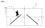
カメラ101で撮像した画像(自車両前方の画像)の具体例を図3に示す。カメラ101による撮像画像3aは、画像左上を原点として左から右へx軸、上から下へy軸とするxy座標系(カメラ座標)によって表される。なお、図3においては、左右の走路脇に設置された縁石、白線、またはガードレールなどの走路端A、およびB、すなわち道路上の境界線と、車両前方に存在する歩行者Cとが撮像画像3a内に含まれている。
A specific example of an image captured by the camera 101 (an image ahead of the host vehicle) is shown in FIG. The captured
制御装置103は、後述するように画像メモリ102に記憶された撮像画像3aを画像処理して、自車両前方に存在する物体の検出を行い、自車両が自車両前方に存在する物体に衝突する危険性がある場合には、スピーカー105を介して運転者に警報(警告音)を出力したり、自動ブレーキ装置106を制御して自車両を自動的に減速、または停止させる。自車両前方に存在する物体の検出を行うに当たっては、まず撮像画像3a内に存在する物体の画像内における横方向(水平方向)の移動速度を検出して、撮像画像3a内における物体の横方向の移動方向と移動速度とを階級値で表した速度画像を生成する。
As will be described later, the
すなわち、カメラ101で撮像された画像を画像メモリ102から読み込み、読み込んだ撮像画像3aに対して所定の閾値を用いて2値化することによって、画像内に存在する物体のエッジを抽出する。そして、抽出した画像内の各エッジに対して、細線化処理を行ってエッジの中心を正確に求める。そして、細線化されたエッジを、エッジ幅が一定の幅、例えば3画素分の幅になるように膨張させる。このように抽出したエッジを正規化することによって、各エッジが均一な幅を持ったエッジ画像を得ることができる。
That is, an image captured by the
図4は、上述した抽出したエッジを正規化して、エッジ画像を得るために行う各処理の具体例を示す図である。すなわち、図4(a)に示す2値化して得たエッジに対して、細線化処理を行って図4(b)に示す細線化後のエッジを得る。そして、細線化したエッジを膨張させ、図4(c)に示すようにエッジに一定の幅を持たせる。 FIG. 4 is a diagram showing a specific example of each process performed to obtain the edge image by normalizing the extracted edge. That is, the thinning process is performed on the edge obtained by binarization shown in FIG. 4A to obtain the thinned edge shown in FIG. 4B. Then, the thinned edge is expanded to give the edge a certain width as shown in FIG.
その後、カウンタメモリ104に保存された画素カウンタの内、現在エッジ画像内にエッジが存在している画素に対応した画素カウンタのカウント値を更新する。画素カウンタとは、エッジ画像の各画素に対応したカウンタであり、エッジが存在する画素に対応する画素カウンタのカウント値に1を加算し、エッジが存在しない画素に対応する画素カウンタのカウント値は0で初期化する。このカウンタ値の更新処理を、カメラ101で連続的に撮像される毎フレームごとに行うことで、エッジ存在時間が長い画素はカウント値が大きく、エッジ存在時間が短い画素はカウント値が小さくなる。
Thereafter, among the pixel counters stored in the
そして、エッジ画像において、横方向に隣接するそれぞれの画素に対応する画素カウンタのカウント値の差分を取ることで各画素におけるエッジ存在時間の差を算出して、当該エッジが1画素移動するのに要する時間を得る。そして、この値の逆数を得ることで、各画素における画像空間内の横方向の速度を算出することができる。この各画素における画像空間内の横方向の速度は、各画素に含まれるエッジの横方向の移動速度に相当する。これによって、画像上の各画素におけるエッジの速度成分、すなわちエッジの移動方向と移動速度とを算出することができる。 In the edge image, the difference in the edge existence time in each pixel is calculated by taking the difference in the count value of the pixel counter corresponding to each pixel adjacent in the horizontal direction, and the edge moves one pixel. Get the time it takes. Then, by obtaining the reciprocal of this value, the lateral speed in the image space at each pixel can be calculated. The horizontal speed in the image space of each pixel corresponds to the horizontal movement speed of the edge included in each pixel. This makes it possible to calculate the edge velocity component at each pixel on the image, that is, the edge movement direction and movement speed.
以上の処理によって算出した撮像画像3a上に存在する物体の速度成分を所定の階級値で表した速度画像を生成する。第1の実施の形態における速度画像では、図5に示す速度画像5aのように、速度成分の階級値として、速度が検出された画素を丸型の点で表し、移動速度が速い画素ほど点を大きく示す。また、右へ向かう速度を黒点で表し、左へ向かう速度を白点で表すことによって移動方向を表している。すなわち、図5においては、走行路右側の走路端Bからは画像の左側へ向かう速度が検出されており、走行路左側の走路端A、および歩行者Cからは画像の右側へ向かう速度が検出されている。また、点の大きさから、走路端AおよびBから検出された移動速度よりも歩行者Cから検出された移動速度の方が速いことが判断できる。
A velocity image in which the velocity component of the object existing on the captured
次に、算出した速度画像5aに走路端などの道路上の境界線を検出するための境界線検出用領域を設定する。境界線検出用領域は、自車両が車線内を走行しながら前方の画像を撮像した場合に、速度画像5a上で道路上の境界線としての走路端が存在する位置をあらかじめ予測しておき、その位置に所定の大きさの領域を設定する。例えば、図6に示すように速度画像5a上で左右に存在する走路端を検出できるように、左右対称となる境界線検出用領域6a〜6hを設定する。そして、設定した境界線検出用領域6a〜6hの中に速度成分を有する斜線が存在するか否かを判定する。すなわち、境界線検出用領域6a〜6hの各領域内において、速度成分を有する画素が斜線を構成するように斜めに並んでいるか否かを判断する。
Next, a boundary line detection region for detecting a boundary line on a road such as a road edge is set in the calculated
そして、左右対称に設定された境界線検出用領域6a〜6hにおいて、それぞれ左右に対となる境界線検出用領域、例えば境界線検出用領域6dおよび6hで斜線が検出された場合に、それぞれで検出された斜線が異なる方向の速度成分を有している場合には、その左右に対となる境界線検出用領域内で検出した斜線は走路端であると判定する。すなわち、境界線検出用領域6dと境界線検出用領域6h内で検出された斜線が異なる方向の速度成分を有している場合には、境界線検出用領域6d、および境界線検出用領域6h内で検出した斜線は走路端であると判定する。
Then, in the boundary line detection areas 6a to 6h set to be symmetrical, when diagonal lines are detected in the pair of boundary line detection areas, for example, the boundary
走路端として検出した各境界線検出用領域内の斜線において、その始点や終点などを代表点として抽出する。例えば境界線検出用領域6aからは代表点6iを抽出し、境界線検出用領域6eからは左代表点6jを抽出する。抽出した各代表点に基づいて、重回帰分析を行い、xy座標系におけるそれぞれの斜線の式を算出することによって次式(1)によって表される2次元道路モデル、すなわち画像道路モデルを算出する。
x=a1・y2+b1・y+c1 ・・・(1)
そして、図7に示すように、自車両の推定進行経路に相当する2次元道路モデルの中心7aを算出する。
In the oblique lines in each boundary line detection area detected as the runway edge, the start point and the end point are extracted as representative points. For example, the representative point 6i is extracted from the boundary line detection region 6a, and the left representative point 6j is extracted from the boundary line detection region 6e. Based on each extracted representative point, a multiple regression analysis is performed, and a two-dimensional road model represented by the following expression (1), that is, an image road model, is calculated by calculating an equation of each oblique line in the xy coordinate system. .
x = a1 · y 2 + b1 · y + c1 (1)
Then, as shown in FIG. 7, the
次に、後述するように2次元道路モデルの中心7aに向かう速度成分を持つ画素を抽出する。そして、抽出した画素の内、同じ速度成分を持つ画素をグルーピングして個別の物体として検出する。まず、図7に示すように速度画像上に所定の範囲を含む領域、例えば縦1画素、横3画素の大きさの領域を下端検出用小領域7bとして設定し、下端検出用小領域7bを速度画像のy軸方向の下から上に走査する。そして、下端検出用小領域7b内に所定以上、例えば2以上の2次元道路モデルの中心7aに向かう同じ速度成分を持つ画素が存在(分布)する点を検出し、そのときに下端検出用小領域7bの下端に位置する画素を物体下端位置7cとして検出する。
Next, as will be described later, a pixel having a velocity component toward the
そして、物体下端位置7cからy軸方向に速度画像のヒストグラムを算出する。すなわち、物体下端位置7cからy軸方向に存在する2次元道路モデルの中心7aに向かう同じ速度成分を持つ画素のx軸方向の度数分布を表すヒストグラムを算出する。そして、このときの物体下端位置7cの座標値をyd、各y座標値における2次元道路モデルの中心7aに向かう同じ速度成分を持つ画素の度数をV(yi)としたときの、あらかじめ設定された歩行者Cの基準高さymの範囲における度数の和を次式(2)により算出する。

式(2)で算出した度数の和が、所定値T1以上であれば、当該2次元道路モデルの中心7aに向かう速度成分を持つ画素が分布している範囲内に2次元道路モデルの中心7aに向かう移動物体が存在すると判定する。そして、移動物体が存在すると判定した場合には、あらかじめ設定された歩行者Cの基準高さym以上となる位置で、かつy座標値における2次元道路モデルの中心7aに向かう速度成分を持つ画素の度数V(yi)が所定値T2未満となる直前の位置、例えば図8に符号8aで示す位置を移動物体が存在する上端位置、すなわち物体上端位置8aとして検出する。
If the sum of the frequencies calculated by equation (2) is equal to or greater than a predetermined value T1, the
さらに、物体下端位置7cと物体上端位置8aとの間の範囲に対して、x軸方向に連続して存在する2次元道路モデルの中心7aに向かう同じ速度成分を持つ画素の最も外側の画素を通るy軸と平行な直線を引き、当該y軸に平行な直線と、物体下端位置7cおよび物体上端位置8aとで囲まれる範囲を移動物体が存在する範囲(物体存在範囲)8bとして特定する。これによって、速度画像5a上において、2次元道路モデルの中心7aに向かう同じ速度成分を持つ画素をグルーピングして、側方から2次元道路モデルの中心7aに向かって移動している歩行者Cを含む物体存在範囲8b検出することができる。
Further, the outermost pixel of the pixels having the same velocity component toward the
上述した処理で検出した速度画像5a上の走路端A、B、および物体存在範囲8bの位置を、実空間上の位置に変換する。このとき、本実施の形態では、自車両の走行中に発生するピッチングを考慮に入れて、以下に説明するように実空間上の位置に変換する。
The positions of the road ends A and B and the
例えば、自車両がピッチングによって沈み込む方向、すなわち下方向に移動している間は、カメラ101の視軸向きは図2に示した路面に水平な状態よりも下向きになる。よってこの場合は、図9に示すように速度画像5a上の時刻tにおける走路端AおよびBの位置から時刻t+1における走路端AおよびBの位置へ上方向に移動する。これによって、走路端Aを示す斜線は速度画像5a上で右方向へ移動するように速度成分が検出され、走路端Bを示す斜線は速度画像5a上で左方向へ移動するように速度成分が検出される。
For example, while the host vehicle is moving in the direction of sinking due to pitching, that is, in the downward direction, the viewing axis direction of the
一方、自車両がピッチングによって浮き上がる方向、すなわち上方向に移動している間は、カメラ101の視軸向きは図2に示した路面に水平な状態よりも上向きになることから、ピッチングに伴って速度画像5a上の走路端AおよびBの位置は下方向に移動する。これによって、走路端Aを示す斜線は速度画像5a上で左方向へ移動するように速度成分が検出され、走路端Bを示す斜線は速度画像5a上で右方向へ移動するように速度成分が検出される。
On the other hand, while the host vehicle is moving upward due to pitching, that is, moving upward, the visual axis direction of the
以上の点を考慮して、走路端AおよびBを示す斜線の画像上における速度の方向が変化する点をピッチングの平衡点、すなわちカメラ101の視軸向きが路面と水平な点であると判断する。そして、このピッチングの平衡点における速度画像5aにおいては、上述したようにカメラ101の視軸向きが路面と水平であることから、走路端AおよびB上に任意に設定した代表点の座標値とカメラ101のカメラパラメータとに基づいて、三角測量により代表点の3次元座標値を算出することが可能となる。
Considering the above points, the point at which the speed direction changes on the hatched image indicating the road ends A and B is determined to be the pitching equilibrium point, that is, the visual axis direction of the
よって、図10に示すように速度画像5a上の走路端AおよびBに任意の代表点10aおよび10bを設定し、この代表点の座標値とカメラ101のカメラパラメータとに基づいて、三角測量により代表点の3次元座標値を算出する。そして、この代表点の3次元座標値に基づいて、走路端AおよびBを示す斜線の位置を実空間上の位置に変換して、3次元道路モデル、すなわち実空間道路モデルを算出する。これによって、2次元道路モデルで表した走路端AおよびBの位置を実空間上の3次元道路モデルに変換することができる。
Therefore, as shown in FIG. 10, arbitrary representative points 10a and 10b are set at the road ends A and B on the
また、速度画像5a上における物体存在範囲8b上に設定した物体中心点10cの座標値と、カメラ101のカメラパラメータとに基づいて、物体存在範囲8bに含まれる歩行者Cの実空間上における位置を算出する。これによって、速度画像5a上の歩行者Cの位置を実空間上の位置に変換することができる。そして、実空間上における走路端A、B、および歩行者Cの位置関係に基づいて、自車両から歩行者Cまでの距離、および歩行者Cから走路端までの距離を算出する。なお、自車両から歩行者Cまでの距離は、自車両から歩行者Cまでの直線距離ではなく、自車両から歩行者Cの存在位置に相当する車線上の位置である。
Further, based on the coordinate value of the object center point 10c set on the
一方、ピッチングの平衡点ではない速度画像5aにおいては、上述したようにカメラ101の視軸向きが路面と水平でないことから、ピッチングの平衡点における速度画像5aにおいて変換した走路端A、B、および歩行者Cの実空間上の位置と、ピッチングの平衡点における速度画像5aと現在の速度画像5aとの撮像時間間隔とに基づいて、それぞれの実空間上における位置を推定する。そして、推定した実空間上における走路端A、B、および歩行者Cの位置関係に基づいて、自車両から歩行者Cまでの距離、および歩行者Cから走路端までの距離を推定する。
On the other hand, in the
そして、走路端AおよびBと、歩行者Cとの実空間上における位置関係に基づいて、自車両と歩行者Cとの接触危険度を以下の(1)〜(3)の3段階のレベルで判定する。
(1)レベル3
走路端と歩行者Cとの実空間上における位置関係から、自車両と歩行者Cとの衝突危険度が最も高いと判定される場合に、接触危険度はレベル3であると判定する。すなわち、図11に示すように、歩行者Cが符号11aに示す左右両側に存在する走路端の内側、すなわち自車両11dが走行中の車線内を移動しているときは、自車両11dと歩行者Cとの衝突危険度はレベル3であると判定する。
Then, based on the positional relationship between the runway ends A and B and the pedestrian C in the real space, the contact risk between the own vehicle and the pedestrian C is set to the following three levels (1) to (3). Judge with.
(1)
When it is determined that the collision risk between the host vehicle and the pedestrian C is the highest from the positional relationship between the runway edge and the pedestrian C in the real space, the contact risk is determined to be
(2)レベル2
走路端と歩行者Cとの実空間上における位置関係から、自車両と歩行者Cとの衝突危険度がレベル3ほどは高くないが、なお衝突の可能性があると判定される場合に、接触危険度はレベル2であると判定する。具体的には、歩行者Cが符号11bに示す範囲、すなわち走路端の外側、かつ走路端から歩行者Cまでの距離がx0(m)以内の範囲を走路端に向かって移動しているときは、自車両11dと歩行者Cとの衝突危険度はレベル2であると判定する。なお、上述した距離x0(m)は、上述した処理で検出した歩行者Cの移動速度、および自車両11dから歩行者Cまでの距離と、車速センサ107で検出した自車両の車速とに基づいて算出される。
(2)
If the collision risk between the host vehicle and the pedestrian C is not as high as
(3)レベル1
走路端と歩行者Cとの実空間上における位置関係から、自車両と歩行者Cとが衝突する危険がないと判定される場合に、接触危険度はレベル1であると判定する。具体的には、歩行者Cが符号11cに示す範囲、すなわち走路端からx0(m)より外側の範囲を移動しているときは、自車両11dと歩行者Cとの衝突危険度はレベル1であると判定する。なお、衝突危険度の判定結果がレベル1である場合には、自車両と歩行者Cとは衝突の危険がないことから、後述する衝突を回避するための車両制御は行わない。
(3)
When it is determined that there is no risk of collision between the host vehicle and the pedestrian C from the positional relationship between the runway edge and the pedestrian C in the real space, the contact risk is determined to be
また、衝突の危険度は、自車両から歩行者Cまでの距離によっても変化するため、自車両から歩行者Cまでの距離を次式(3)〜(5)で算出される距離で分類し、この分類結果に基づいて、後述するように自車両と歩行者Cとの衝突を回避するための車両制御を行う。なお、次式(3)〜(5)において、Vは自車両11dの車速、gは重力加速度、z0は歩行者Cの存在位置に相当する車線上の位置から目標停止ラインまでの距離11eである。
z3=(1/2)*(V2*0.5g)+V*2+z0 ・・・(3)
z2=(1/2)*(V2*0.5g)+V*1+z0 ・・・(4)
z1=(1/2)*(V2*0.6g)+z0 ・・・(5)
Moreover, since the risk of collision also changes depending on the distance from the own vehicle to the pedestrian C, the distance from the own vehicle to the pedestrian C is classified by the distance calculated by the following equations (3) to (5). Based on the classification result, vehicle control for avoiding a collision between the host vehicle and the pedestrian C is performed as described later. In the following formulas (3) to (5), V is the vehicle speed of the host vehicle 11d, g is the gravitational acceleration, and z0 is the distance 11e from the position on the lane corresponding to the position where the pedestrian C exists to the target stop line. is there.
z3 = (1/2) * (V 2 * 0.5 g) + V * 2 + z0 (3)
z2 = (1/2) * (V 2 * 0.5 g) + V * 1 + z0 (4)
z1 = (1/2) * (V 2 * 0.6 g) + z0 (5)
上述した処理で判定した衝突危険度と、式(3)〜(5)により分類した自車両から歩行者Cまでの距離とに基づいて、以下の(A)〜(C)の3つの制御モードによって歩行者Cとの衝突を回避するための車両制御を行う。 The following three control modes (A) to (C) based on the collision risk determined by the above-described processing and the distance from the own vehicle to the pedestrian C classified by the equations (3) to (5). The vehicle control for avoiding the collision with the pedestrian C is performed.
(A)注意
衝突危険度がレベル3であり、かつ自車両から歩行者Cまでの距離がz2より長くz3以下である場合に制御モードを「注意」とする。制御モードが「注意」の場合は、スピーカー105を介して注意音を出力することによって、運転者に対して自車両前方に衝突の危険がある移動物体が存在することを報知する。
(A) Caution When the collision risk is
(B)警告
衝突危険度がレベル2の場合、および衝突危険度がレベル3であり、かつ自車両から歩行者Cまでの距離がz2以下である場合に制御モードを「警告」とする。制御モードが「警告」の場合は、ピーカー105を介して警告音を出力することによって、運転者に対して自車両前方に衝突の危険性が高い移動物体が存在することを警告する。なお、警告音は、(A)で上述した「注意」における注意音と運転者が識別可能なように、例えば注意音よりも警告音の音量を大きくしたり、注意音と警告音のリズムを変更したりする。
(B) Warning The control mode is set to “warning” when the collision risk is
(C)自動ブレーキ
衝突危険度はレベル3であり、かつ自車両から歩行者Cまでの距離がz1以下である場合に、制御モードを「自動ブレーキ」とする。制御モードが「自動ブレーキ」の場合は、自動ブレーキ装置106を制御して、自車両を強制的に制動する。すなわち、歩行者Cとの衝突危険視が極めて高い場合には、運転者が上述した注意音や警告音を認知してから制動動作に入っても間に合わない可能性がある。よって、このような場合には、自動ブレーキ装置106を制御して自車両を強制的に停止させる。なお、制御モードを「自動ブレーキ」としたときは、同時に「警告」も行う。
(C) Automatic brake When the collision risk is
図12は、第1の実施の形態における物体検出装置100の処理を示すフローチャートである。図12に示す処理は車両のイグニションスイッチがオンされて、物体検出装置100の電源がオンされると、制御装置103によって起動されるプログラムとして実行される。ステップS1において、カメラ101で撮像された自車両前方の画像3aを画像メモリ102から取り込む。その後、ステップS2へ進み、画像3aに対してエッジ抽出処理を行って、撮像画像3a内に存在する物体の輪郭を抽出したエッジ画像を生成し、ステップS3へ進む。ステップS3では、上述したように各画素に含まれるエッジの速度情報を算出し、算出した速度情報を所定の階調値に変換した速度画像を算出する。その後、ステップS4へ進む。
FIG. 12 is a flowchart showing processing of the
ステップS4では、算出した速度画像上に境界線検出用領域を設定して、ステップS5へ進む。ステップS5では、境界線検出用領域内に速度成分を有する画素が斜線を構成するように斜めに並んでいるか否かを判断して斜線を検出する。その後、ステップS6へ進み、左右に対となる境界線検出用領域で検出された斜線が異なる方向の速度成分を有しているか否かを判定して、検出した斜線が走路端であるか否かを判定する。検出した斜線が走路端でないと判断した場合には、後述するステップS22へ進む。一方、検出した斜線が走路端であると判断した場合には、ステップS7へ進む。 In step S4, a boundary line detection region is set on the calculated speed image, and the process proceeds to step S5. In step S5, it is determined whether or not pixels having velocity components are arranged diagonally so as to form a diagonal line in the boundary line detection region, and the diagonal line is detected. Thereafter, the process proceeds to step S6, where it is determined whether or not the diagonal lines detected in the left and right paired boundary line detection areas have velocity components in different directions, and whether or not the detected diagonal line is the road edge. Determine whether. If it is determined that the detected oblique line is not the end of the road, the process proceeds to step S22 described later. On the other hand, if it is determined that the detected diagonal line is the end of the road, the process proceeds to step S7.
ステップS7では、上述したように2次元道路モデル、すなわち画像道路モデルを算出して、ステップS8へ進む。ステップS8では、2次元道路モデルの中心に向かう速度成分を持つ画素を抽出する。その後、ステップS9へ進み、抽出した画素の内、同じ速度成分を持つ画素をグルーピングして個別の物体として検出して、ステップS10へ進む。ステップS10では、抽出した画素のグルーピングが完了し、速度画像上に存在する全ての物体が検出されたか否かを判断する。速度画像上に存在する全ての物体が検出されたと判断した場合には、ステップS11へ進む。 In step S7, as described above, a two-dimensional road model, that is, an image road model is calculated, and the process proceeds to step S8. In step S8, a pixel having a speed component toward the center of the two-dimensional road model is extracted. Thereafter, the process proceeds to step S9, and pixels having the same velocity component among the extracted pixels are grouped and detected as individual objects, and the process proceeds to step S10. In step S10, it is determined whether or not the grouping of the extracted pixels has been completed and all objects present on the speed image have been detected. If it is determined that all objects present on the speed image have been detected, the process proceeds to step S11.
ステップS11では、走路端を示す斜線の画像上における速度方向の変化を検出してピッチングの平衡点であるか否かを判断する。ピッチングの平衡点であると判断した場合には、ステップS12へ進む。ステップS12では、走路端を示す斜線の位置を実空間上の位置に変換して、3次元道路モデルを算出する。その後、ステップS14に進み、実空間上における走路端と検出物体との相対的な位置関係、すなわち走路端と検出物体との距離、および自車両と検出物体との距離を算出して、後述するステップS16へ進む。 In step S11, it is determined whether or not it is a pitching equilibrium point by detecting a change in the speed direction on the hatched image indicating the road edge. If it is determined that the pitching equilibrium point, the process proceeds to step S12. In step S12, a three-dimensional road model is calculated by converting the position of the oblique line indicating the end of the road to a position in real space. Thereafter, the process proceeds to step S14, and the relative positional relationship between the road edge and the detected object in the real space, that is, the distance between the road edge and the detected object, and the distance between the host vehicle and the detected object are calculated and described later. Proceed to step S16.
一方、ピッチングの平衡点でないと判断した場合には、ステップS13へ進む。ステップS13では、上述したように、ピッチングの平衡点における速度画像と現在の速度画像との撮像時間間隔とに基づいて3次元道路モデルを推定し、ステップS15へ進む。ステップS15では、実空間上における走路端と検出物体との相対的な位置関係、すなわち走路端と検出物体との距離、および自車両と検出物体との距離を推定して、ステップS16へ進む。 On the other hand, if it is determined that the point is not a pitching equilibrium point, the process proceeds to step S13. In step S13, as described above, a three-dimensional road model is estimated based on the imaging time interval between the velocity image at the pitching equilibrium point and the current velocity image, and the process proceeds to step S15. In step S15, the relative positional relationship between the road edge and the detected object in real space, that is, the distance between the road edge and the detected object, and the distance between the host vehicle and the detected object are estimated, and the process proceeds to step S16.
ステップS16では、走路端と、検出物体との実空間上における位置関係に基づいて、自車両と検出物体との接触危険度が上述したレベル1〜レベル3のいずれであるかを判定する。接触危険度がレベル1であると判定した場合には、自車両と検出物体とは衝突の危険がないことから、衝突を回避するための車両制御は行わず、後述するステップS22へ進む。これに対して、接触危険度がレベル2または3であると判定した場合には、ステップS17へ進む。ステップS17では、自車両から検出物体までの距離に基づいて、衝突を回避するための車両制御のモードを判定する。
In step S16, based on the positional relationship between the road edge and the detected object in real space, it is determined whether the contact risk between the host vehicle and the detected object is
制御モードが上述した「注意」である場合には、ステップS19へ進み、スピーカー105を介して注意音を出力して、後述するステップS22へ進む。これに対して、制御モードが「警告」、または「自動ブレーキ」である場合には、ステップS18へ進み、スピーカー105を介して警告音を出力して、ステップS20へ進む。ステップS20では、制御モードが「自動ブレーキ」であるか否かを判定する。制御モードが「自動ブレーキ」でない場合には、後述するステップS22へ進む。一方、制御モードが「自動ブレーキ」である場合には、ステップS21へ進む。
When the control mode is “CAUTION” described above, the process proceeds to step S19, a caution sound is output through the
ステップS21では、自動ブレーキ装置106を制御して、自車両を強制的に制動する。その後、ステップS22へ進む。ステップS22では、自車両のイグニションスイッチがオフされたか否かを判断し、オフされないと判断した場合には、ステップS1へ戻って処理を繰り返す。これに対して、自車両のイグニションスイッチがオフされたと判断した場合には、処理を終了する。
In step S21, the
以上説明した第1の実施の形態によれば、以下のような作用効果を得ることができる。
(1)カメラ101で撮像した画像に基づいて算出した速度画像上に境界線検出用領域を設定し、それぞれ左右に対となる境界線検出用領域で検出された斜線が異なる方向の速度成分を有している場合には、その左右に対となる境界線検出用領域内で検出した斜線は道路上の境界線、すなわち走路端であると判定することとした。これによって、カメラ101で撮像した画像に含まれる走路端は光軸と平行な直線成分のため、画像上では必ず斜線として撮像され、さらに斜線は速度が発生しやすいことを加味して、精度高く走路端を検出することができる。
According to the first embodiment described above, the following operational effects can be obtained.
(1) A boundary line detection region is set on a velocity image calculated based on an image captured by the
(2)走路端AおよびBを示す斜線の画像上における速度の方向が変化する点をピッチングの平衡点と判断するようにした。これによって、画像上における斜線の速度方向を計測するだけで,容易にピッチングの平衡点が検出できる。 (2) The point at which the speed direction changes on the hatched image indicating the road ends A and B is determined as the pitching equilibrium point. As a result, the pitching equilibrium point can be easily detected simply by measuring the speed direction of the oblique lines on the image.
(3)ピッチングの平衡点における走路端AおよびBにおける代表点の座標値とカメラ101のカメラパラメータとに基づいて、三角測量により代表点の3次元座標値を算出するようにした。これによって、ピッチング平衡点ではカメラパラメータは取付時の初期状態とほぼ一致するため三角測量の測距の精度が高いことを加味して、精度高く3次元座標値を算出することができる。
(3) The three-dimensional coordinate value of the representative point is calculated by triangulation based on the coordinate value of the representative point at the runway ends A and B at the equilibrium point of pitching and the camera parameters of the
(4)走路端AおよびBと、歩行者Cとの実空間上における相対的な位置関係に基づいて、自車両と歩行者Cとの接触危険度を判定し、さらに自車両と歩行者Cとの距離を加味して歩行者Cとの衝突を回避するための車両制御を行うようにした。これによって、危険度を正確に判定することができ、さらに自車両と歩行者Cとの衝突を防止することができる。 (4) Based on the relative positional relationship between the road ends A and B and the pedestrian C in the real space, the contact risk between the host vehicle and the pedestrian C is determined, and the host vehicle and the pedestrian C are further determined. The vehicle control for avoiding the collision with the pedestrian C is taken into consideration. As a result, the degree of danger can be accurately determined, and a collision between the host vehicle and the pedestrian C can be prevented.
―第2の実施の形態―
第2の実施の形態では、第1の実施の形態で検出した自車両の両側に対で存在する走路端だけではなく、例えば複数車線道路における隣接する複数の車線の境界線や道路と建物の境界線などといった種々の道路上の境界線を検出する。
-Second embodiment-
In the second embodiment, not only the road ends that exist in pairs on both sides of the host vehicle detected in the first embodiment, but also, for example, border lines of a plurality of adjacent lanes or roads and buildings in a multi-lane road Detect boundary lines on various roads such as boundary lines.
なお、図1に示したブロック図、図2に示した車両へのカメラ101の設置例を示す図、および図4に示したエッジの正規化の例を示す図については、第1の実施の形態と同様のため説明を省略する。また、図7〜11で説明した、検出した走路端に基づいて2次元道路モデルの算出処理、および2次元道路モデルの中心に向かう物体を含む物体存在範囲の検出処理、3次元道路モデル上に変換した道路上の境界線と物体との位置関係に基づく危険度判定処理、および危険度判定結果に基づく車両制御または警告処理については、第1の実施の形態における処理と同様のため説明を省略する。
The block diagram shown in FIG. 1, the diagram showing the installation example of the
図13は、第2の実施の形態におけるカメラ101で撮像した撮像画像の具体例を示す図である。撮像画像13aは、第1の実施の形態と同様に、画像左上を原点として左から右へx軸、上から下へy軸とするxy座標系(カメラ座標)によって表される。なお、図13に示す例では、撮像画像13aには、道路上の境界線として、走路脇に設置された縁石、白線、ガードレールなどの走路端DおよびEと、隣接する車線との境界線Fと、車両前方に存在する歩行者Gとが含まれている。
FIG. 13 is a diagram illustrating a specific example of a captured image captured by the
この図13に示す撮像画像13aを第1の実施の形態と同様に画像処理して、図14に示すような速度画像14aを生成する。そして、この速度画像14a内の所定範囲を分割して得られる複数の境界線検出用領域を設定する。すなわち、図15に示すように、自車両前方の所定範囲、例えば、実空間上における自車両からの距離が20m〜60mの範囲を、画像の縦方向(y軸方向)に所定の高さを有する複数領域に6分割する。そして、この縦方向に分割した各領域を画像の横方向に等間隔に分割することによって、画像上の自車両前方の所定範囲に相当する範囲内に複数の境界線検出用領域15aを設定することができる。
The captured
このように設定したそれぞれの境界線検出領域15aを、さらに所定の大きさを有する小領域に分割する。本実施の形態では、例えば、各境界線検出領域15a内を64等分した小領域に分割する。これによって、各境界線検出領域15aは、8×8の小領域によって構成されるようになる。そして、分割して得られる各小領域ごとに、速度画像14a内に存在する道路上の境界線の候補を検出する。
Each
ここで、走路端などの道路上の境界線は、第1の実施の形態と同様に、速度画像14a上では斜線として検出されることを加味して、各小領域内で斜線を構成するように斜めに並んでいる速度成分を有する画素を検出することによって、各小領域内における斜線の候補、すなわち道路上の境界線の候補を検出する。
Here, in the same manner as in the first embodiment, the boundary line on the road such as the end of the road is detected as a diagonal line on the
まず、各小領域内に存在する任意の画素を注目画素として、その注目画素が、斜め方向に隣接する近傍画素と斜線を構成するか否かを判定する。よって、注目画素と斜めに直線を構成する近傍画素が、それぞれ速度成分を有しているかを判定するために、着目画素に対して、例えば、図16(b)に示す斜線候補検出用の空間フィルタを適用する。このとき、空間フィルタの中心16aが着目画素と一致するように、空間フィルタを適用する。
First, an arbitrary pixel existing in each small area is set as a target pixel, and it is determined whether or not the target pixel forms a diagonal line with a neighboring pixel adjacent in an oblique direction. Therefore, in order to determine whether neighboring pixels that form a straight line obliquely with the pixel of interest each have a velocity component, for example, a hatched candidate detection space shown in FIG. Apply a filter. At this time, the spatial filter is applied so that the
なお、速度画像14a内においては、一般的に自車両の右側に存在する道路上の境界線は、走路端Eや隣接する車線との境界線Fのように左上がりの斜線として撮像され、自車両の左側に存在する道路上の境界線は、走路端Dのように右上がりの斜線として撮像される。よって、速度画像14aの右側半分の範囲内に存在する着目画素に対しては左上がりの斜線を検出するための空間フィルタ、すなわち図16(b)に示す空間フィルタを適用し、速度画像14aの左側半分の範囲内に存在する着目画素に対しては、右上がりの斜線を検出するための空間フィルタ、すなわち図16(b)に示す空間フィルタを左右に反転させたもの適用する。
In the
このように、着目画素に対して空間フィルタを適用した結果、着目画素と、その斜め上方の画素、および斜め下方の画素の少なくともいずれか一方とが、それぞれ速度成分を有していると判定した場合には、当該着目画素を斜線を構成する点の候補、すなわち候補点として検出する。この処理を小領域内の全ての画素に対して行い、小領域内から全ての候補点を検出する。そして、小領域内で、3点以上の候補点が小領域内で斜線を構成するように斜めに並んでおり、かつこれらの候補点を結んだ直線が、次に説明する傾き条件を満たしている場合には、これらの候補点を結んだ直線、すなわち斜線を道路上の境界線の候補(境界線候補)として検出する。 As described above, as a result of applying the spatial filter to the target pixel, it is determined that the target pixel and at least one of the diagonally upper pixel and the diagonally lower pixel each have a velocity component. In this case, the target pixel is detected as a candidate for a point constituting a diagonal line, that is, a candidate point. This process is performed for all the pixels in the small area, and all candidate points are detected from the small area. In the small area, three or more candidate points are arranged obliquely so as to form a diagonal line in the small area, and the straight line connecting these candidate points satisfies the inclination condition described below. If there is a line, a straight line connecting these candidate points, that is, a diagonal line, is detected as a boundary line candidate (boundary line candidate) on the road.
ここで、境界線候補を検出するための傾き条件について説明する。一般的に、速度画像14a内の自車両から見た左右のいずれか片方の方向、すなわち右側、または左側に、複数の道路上の境界線が存在する場合には、それぞれの境界線の傾きは、自車両に近い境界線の傾きの方が、自車両から遠い境界線の傾きよりも大きくなる。換言すれば、自車両に近い境界線の方が、自車両から遠い境界線よりもx軸とのなす角が大きくなる。例えば、図14に示す例では、自車両の右側に存在する走路端Eの傾きは、隣接する車線との境界線Fの傾きよりも大きくなる。
Here, an inclination condition for detecting a boundary line candidate will be described. In general, when there are boundary lines on a plurality of roads in one of the left and right directions as viewed from the host vehicle in the
よって、このことを加味して、上述した処理で検出した候補点を結んだ直線が境界線候補であるか否かを次のように判断する。例えば、図16(a)に示すように、小領域16b内から候補点を結んだ直線が検出された場合には、自車両から見た同じ側で、かつ同じ高さ位置に存在する他の小領域内から候補点を結んだ直線が検出されているか否かを判定する。その結果、もし小領域16bと自車両から見た同じ側で、かつ同じ高さ位置に存在する他の小領域内から候補点を結んだ直線が検出されていないと判定した場合には、小領域16bに存在する候補点を結んだ直線を境界線候補として検出する。 Therefore, in consideration of this, it is determined as follows whether or not a straight line connecting candidate points detected by the above-described processing is a boundary line candidate. For example, as shown in FIG. 16 (a), when a straight line connecting candidate points is detected from within the small area 16b, another line existing on the same side as seen from the own vehicle and at the same height position. It is determined whether or not a straight line connecting candidate points is detected from within the small area. As a result, if it is determined that a straight line connecting candidate points is not detected from other small areas on the same side as the small area 16b from the own vehicle and at the same height, A straight line connecting candidate points existing in the region 16b is detected as a boundary line candidate.
これに対して、小領域16bと自車両から見た同じ側で、かつ同じ高さ位置に存在する他の小領域、例えば小領域16cから候補点を結んだ直線が検出されている場合には、それぞれの小領域内で検出された候補点を結んだ直線の傾きを比較して、自車両に近い直線の傾きの方が、自車両から遠い方の直線の傾きよりも大きいか否かを判定する。そして、自車両に近い方の直線の傾きの方が、自車両から遠い直線の傾きよりも大きいと判定した場合には、いずれも道路の境界線の一部を構成する境界線候補として検出する。一方、自車両に近い方の直線の傾きの方が、自車両から遠い方の直線の傾きよりも小さいと判定した場合には、いずれも境界線候補から除外する。
On the other hand, in the case where a straight line connecting candidate points is detected from another small region, for example, the
このように検出したそれぞれの境界線候補の、速度画像14a上における縦方向、すなわち上下方向の斜線としての連続性を判定し、複数の境界線候補で連続性が確認された場合には、それらの境界線候補を結んだ直線を、道路上の境界線として検出する。これによって、図17に示すように、速度画像14a内から、道路上の境界線D、E、およびFを検出することができる。
The continuity of each boundary line candidate detected in this way is determined as a vertical direction on the
図18は、第2の実施の形態における物体検出装置100の処理を示すフローチャートである。図18に示す処理は、車両のイグニションスイッチがオンされて、物体検出装置100の電源がオンされると、制御装置103によって起動されるプログラムとして実行される。なお、図18においては、図12に示す第1の実施の形態における処理と同一の処理内容については、同じステップ番号を付与し、相違点を中心に説明する。
FIG. 18 is a flowchart illustrating the processing of the
ステップS4−2において、上述したように速度画像14a上に複数の境界線検出用領域15aを設定して、それぞれの境界線検出領域15aを、さらに所定の大きさを有する小領域に分割する。その後、ステップS5−2へ進む。ステップS5−2では、各小領域内の着目画素に図16(b)で上述した空間フィルタを適用して候補点を検出した後、検出した3点以上の候補点が小領域内で斜線を構成するように斜めに並んでおり、かつこれらの候補点を結んだ直線が上述した傾き条件を満たしている場合には、これらの候補点を結んだ直線を境界線候補として検出する。
In step S4-2, as described above, a plurality of boundary
その後、ステップS6−2へ進み、速度画像14a上で検出したそれぞれの境界線候補の、速度画像14a上における縦方向、すなわち上下方向の斜線としての連続性を判定した結果、それらの境界線候補を結んだ直線が道路上の境界線として検出されたか否かを判定する。そして、道路上の境界線が検出されたと判断した場合にはステップS7へ進み、検出されないと判断した場合にはステップS22へ進む。
Thereafter, the process proceeds to step S6-2, where the continuity of each boundary line candidate detected on the
以上説明した第2の実施の形態によれば、速度画像14a内の所定範囲内、例えば実空間上における自車両からの距離が20m〜60mの範囲内に複数の境界線検出用領域を設定して、それぞれの境界線検出用領域ごとに斜線の候補を検出して、道路上の境界線を検出するようにした。このため、第1の実施の形態による効果に加えて、自車両の両側に対で存在する走路端だけではなく、例えば複数車線道路における隣接する複数の車線の境界線や道路と建物の境界線などといった種々の境界線を道路上の境界線として検出することができる。
According to the second embodiment described above, a plurality of boundary line detection regions are set within a predetermined range in the
上述した実施の形態における物体検出装置100は、以下のように変形することもできる。
(1)上述した第1および第2の実施の形態では、撮像画像に対してエッジ抽出処理を行ってエッジ画像を得た後、エッジが存在する画素の画素カウンタを更新していき、当該画素カウンタのカウント値に基づいて画像上の各画素におけるエッジの速度成分を算出する例について説明した。しかし、これに限定されず、例えば一般的な手法である勾配法やブロックマッチングを用いてオプティカルフローを算出してもよい。
The
(1) In the first and second embodiments described above, after performing edge extraction processing on a captured image to obtain an edge image, the pixel counter of the pixel in which the edge exists is updated, and the pixel The example in which the edge velocity component in each pixel on the image is calculated based on the count value of the counter has been described. However, the present invention is not limited to this, and the optical flow may be calculated using, for example, a general method such as a gradient method or block matching.
(2)上述した第1および第2の実施の形態では、図5に示す階級値を使用して速度画像5aを算出する例について説明した。しかし、これに限定されず、その他の階級値によって表される速度画像を算出してもよい。
(2) In the above-described first and second embodiments, the example in which the
(3)上述した第1および第2の実施の形態では、本発明による物体検出装置100を車両に搭載する例について説明したが、これに限定されず、その他の移動体に搭載してもよい。
(3) In the above-described first and second embodiments, the example in which the
(4)上述した第2の実施の形態では、速度画像14a内の所定範囲内、例えば実空間上における自車両からの距離が20m〜60mの範囲内に複数の境界線検出用領域を設定する例について説明した。しかしこれに限定されず、速度画像14a全体に境界線検出用領域を設定してもよく、あるいは道路上の境界が存在する可能性が高い範囲、例えば速度画像14aの左右の所定範囲内にのみ境界線検出用領域を設定してもよい。
(4) In the second embodiment described above, a plurality of boundary line detection regions are set within a predetermined range in the
また、本発明の特徴的な機能を損なわない限り、本発明は、上述した実施の形態における構成に何ら限定されない。 In addition, the present invention is not limited to the configurations in the above-described embodiments as long as the characteristic functions of the present invention are not impaired.
特許請求の範囲の構成要素と実施の形態との対応関係について説明する。カメラ101は撮像手段に、スピーカー105、および自動ブレーキ装置106は危険回避手段に相当する。制御装置103は速度情報算出手段、画素抽出手段、斜線検出手段、境界線検出手段、平衡点判定手段、物体検出手段、変換手段、および衝突危険度判定手段に相当する。なお、この対応は一例であり、実施の形態の構成によって対応関係は異なるものである。
The correspondence between the constituent elements of the claims and the embodiment will be described. The
100 物体検出装置
101 カメラ
102 画像メモリ
103 制御装置
104 カウンタメモリ
105 スピーカー
106 自動ブレーキ装置
107 車速センサ
DESCRIPTION OF
Claims (7)
前記速度成分算出手段で算出した各画素における前記エッジの速度成分に基づいて、速度成分を有する画素を抽出する画素抽出手段と、
前記画素抽出手段で抽出した速度成分を有する画素によって構成される斜線を検出する斜線検出手段と、
前記斜線検出手段で検出した斜線に基づいて、前記自車両前方の画像内に存在する道路上の境界線を検出する境界線検出手段とを備えることを特徴とする物体検出装置。 By binarizing the image of the vehicle ahead that is captured by the imaging means, and extracting an edge from within the image, and the speed component calculating means for calculating the velocity component of the edge in each pixel,
Pixel extraction means for extracting a pixel having a speed component based on the speed component of the edge in each pixel calculated by the speed component calculation means;
Oblique line detecting means for detecting oblique lines constituted by pixels having velocity components extracted by the pixel extracting means;
An object detection apparatus comprising: boundary line detection means for detecting a boundary line on a road existing in an image ahead of the host vehicle based on the oblique line detected by the oblique line detection means.
前記境界線検出手段は、前記斜線検出手段で検出した斜線が自車両前方の画像上で左右対称に位置し、それぞれの速度方向が異なる場合には、これらの斜線は自車両が走行中の走路の走路端であると判定することを特徴とする物体検出装置。 The object detection apparatus according to claim 1,
In the case where the oblique lines detected by the oblique line detection means are symmetrically positioned on the image ahead of the host vehicle and the speed directions are different from each other, the boundary line detection unit indicates that the oblique line is a path on which the host vehicle is traveling. It is determined that the end of the road is an object detection device.
前記境界線検出手段は、前記斜線検出手段によって複数の斜線が検出された場合には、前記自車両前方の画像の中心から外側にいくにつれて斜線の傾きが小さくなる場合に、これらの斜線を前記道路上の境界線として検出することを特徴とする物体検出装置。 The object detection apparatus according to claim 1,
When a plurality of oblique lines are detected by the oblique line detection unit, the boundary line detection unit converts these oblique lines when the inclination of the oblique lines decreases from the center of the image ahead of the host vehicle toward the outside. An object detection apparatus for detecting a boundary line on a road.
前記斜線検出手段で検出した斜線の速度方向が変化する変化点を検出して、当該変化点を自車両の走行中に発生したピッチングの平衡点であると判定する平衡点判定手段をさらに備えることを特徴とする物体検出装置。 In the object detection device according to any one of claims 1 to 3,
The apparatus further comprises an equilibrium point determination unit that detects a change point at which the speed direction of the oblique line detected by the oblique line detection unit changes, and determines that the change point is an equilibrium point of pitching generated during traveling of the host vehicle. An object detection device characterized by.
前記画素抽出手段で抽出した画素のうち、自車両の推定進行経路に側方から向かう速度成分を有する画素をグルーピングして、前記自車両の推定進行先に接近してくる移動物体を検出する物体検出手段と、
前記平衡点判定手段でピッチングの平衡点であると判定された自車両前方の画像において、前記境界線検出手段で前記道路上の境界線であると判定された斜線、および前記物体検出手段で検出された前記移動物体を実空間道路モデル上に変換して配置する変換手段と、
前記変換手段で実空間道路モデル上に配置した前記道路上の境界線および前記移動物体と、自車両との位置関係に基づいて、自車両と前記移動物体との衝突危険度を判定する衝突危険度判定手段とをさらに備えることを特徴とする物体検出装置。 The object detection device according to claim 4,
An object for detecting a moving object approaching the estimated travel destination of the host vehicle by grouping pixels having a speed component directed from the side to the estimated travel path of the host vehicle among the pixels extracted by the pixel extracting means Detection means;
In the image ahead of the host vehicle determined to be a pitching equilibrium point by the equilibrium point determination means, the diagonal line determined to be a boundary line on the road by the boundary detection means, and detected by the object detection means Conversion means for converting and arranging the moved moving object on a real space road model;
Collision risk for determining a collision risk between the own vehicle and the moving object based on a positional relationship between the boundary line on the road and the moving object arranged on the real space road model by the converting means and the own vehicle An object detection device further comprising a degree determination unit.
前記衝突危険度判定手段は、自車両と前記移動物体との衝突危険度をその危険度の高さに応じた複数の危険度レベルに分類して判定し、
前記衝突危険度判定手段で判定された危険度レベルに応じて、自車両と前記移動物体との衝突を回避するように車両を制御する危険回避手段をさらに備えることを特徴とする物体検出装置。 The object detection apparatus according to claim 5,
The collision risk determination means classifies and determines the collision risk between the own vehicle and the moving object into a plurality of risk levels according to the height of the risk,
An object detection apparatus, further comprising: a risk avoidance unit that controls the vehicle so as to avoid a collision between the host vehicle and the moving object according to the risk level determined by the collision risk determination unit.
算出した各画素における前記エッジの速度成分に基づいて、速度成分を有する画素を抽出し、
抽出した速度成分を有する画素によって構成される斜線を検出し、
検出した斜線に基づいて、前記自車両前方の画像内に存在する道路上の境界線を検出することを特徴とする物体検出方法。
Binarize the image ahead of the host vehicle imaged by the imaging means, extract an edge from the image, calculate the velocity component of the edge at each pixel,
Based on the calculated velocity component of the edge in each pixel, extract a pixel having a velocity component,
Detect diagonal lines composed of pixels with extracted velocity components,
Based on the detected oblique lines, the object detection attitude method characterized by detecting the boundary line on the road present in the vehicle in front of the image.
Priority Applications (5)
| Application Number | Priority Date | Filing Date | Title |
|---|---|---|---|
| JP2005123494A JP4650079B2 (en) | 2004-11-30 | 2005-04-21 | Object detection apparatus and method |
| US10/575,283 US7747039B2 (en) | 2004-11-30 | 2005-11-29 | Apparatus and method for automatically detecting objects |
| DE602005026847T DE602005026847D1 (en) | 2004-11-30 | 2005-11-29 | DEVICE AND METHOD FOR AUTOMATIC RECORDING OF OBJECTS |
| EP05810778A EP1817761B1 (en) | 2004-11-30 | 2005-11-29 | Apparatus and method for automatically detecting objects |
| PCT/IB2005/003579 WO2006059201A2 (en) | 2004-11-30 | 2005-11-29 | Apparatus and method for automatically detecting objects |
Applications Claiming Priority (2)
| Application Number | Priority Date | Filing Date | Title |
|---|---|---|---|
| JP2004346670 | 2004-11-30 | ||
| JP2005123494A JP4650079B2 (en) | 2004-11-30 | 2005-04-21 | Object detection apparatus and method |
Publications (2)
| Publication Number | Publication Date |
|---|---|
| JP2006185406A JP2006185406A (en) | 2006-07-13 |
| JP4650079B2 true JP4650079B2 (en) | 2011-03-16 |
Family
ID=36565405
Family Applications (1)
| Application Number | Title | Priority Date | Filing Date |
|---|---|---|---|
| JP2005123494A Active JP4650079B2 (en) | 2004-11-30 | 2005-04-21 | Object detection apparatus and method |
Country Status (5)
| Country | Link |
|---|---|
| US (1) | US7747039B2 (en) |
| EP (1) | EP1817761B1 (en) |
| JP (1) | JP4650079B2 (en) |
| DE (1) | DE602005026847D1 (en) |
| WO (1) | WO2006059201A2 (en) |
Cited By (1)
| Publication number | Priority date | Publication date | Assignee | Title |
|---|---|---|---|---|
| JP2008077624A (en) * | 2005-12-07 | 2008-04-03 | Nissan Motor Co Ltd | Object detecting device and object detecting method |
Families Citing this family (47)
| Publication number | Priority date | Publication date | Assignee | Title |
|---|---|---|---|---|
| WO2004004570A1 (en) * | 2002-07-09 | 2004-01-15 | Anglo-European College Of Chiropractic Ltd | Method for imaging the relative motion of skeletal segments |
| JP4026641B2 (en) * | 2004-12-03 | 2007-12-26 | 日産自動車株式会社 | Object detection apparatus and object detection method |
| DE102005030838A1 (en) * | 2005-07-01 | 2007-01-04 | Siemens Ag | Night Vision System |
| DE602006020231D1 (en) * | 2005-12-06 | 2011-04-07 | Nissan Motor | Detection device and method |
| JP4811201B2 (en) * | 2005-12-06 | 2011-11-09 | 日産自動車株式会社 | Runway boundary line detection apparatus and runway boundary line detection method |
| US8164628B2 (en) * | 2006-01-04 | 2012-04-24 | Mobileye Technologies Ltd. | Estimating distance to an object using a sequence of images recorded by a monocular camera |
| JP4426535B2 (en) * | 2006-01-17 | 2010-03-03 | 本田技研工業株式会社 | Vehicle periphery monitoring device |
| DE102006058308A1 (en) * | 2006-12-11 | 2008-06-12 | Robert Bosch Gmbh | Method and device for detecting an obstacle in a surrounding area of a motor vehicle and motor vehicle |
| DE102007022524A1 (en) * | 2007-05-14 | 2008-11-20 | Bayerische Motoren Werke Aktiengesellschaft | motor vehicle |
| JP5014237B2 (en) * | 2008-04-23 | 2012-08-29 | 本田技研工業株式会社 | Lane marker recognition device, vehicle, and lane marker recognition program |
| EP2291836B1 (en) | 2008-05-21 | 2018-09-12 | ADC Automotive Distance Control Systems GmbH | Driver assistance system for preventing a vehicle colliding with pedestrians |
| TW201002073A (en) * | 2008-06-23 | 2010-01-01 | Huper Lab Co Ltd | Method of vehicle segmentation and counting for nighttime video frames |
| NL1035766C2 (en) * | 2008-07-29 | 2009-08-12 | Melchior Frederik Leipoldt | Sensors for e.g. truck, placed on sides of vehicle and activated or deactivated by actuation of vehicle in specific direction, where signals from sensors are delivered to person or object |
| JP5089545B2 (en) * | 2008-09-17 | 2012-12-05 | 日立オートモティブシステムズ株式会社 | Road boundary detection and judgment device |
| JP5150527B2 (en) | 2009-02-03 | 2013-02-20 | 株式会社日立製作所 | Vehicle collision avoidance support device |
| JP5401257B2 (en) * | 2009-10-23 | 2014-01-29 | クラリオン株式会社 | Far-infrared pedestrian detection device |
| JP5321497B2 (en) * | 2010-02-22 | 2013-10-23 | 株式会社デンソー | White line recognition device |
| DE102010020984A1 (en) * | 2010-04-20 | 2011-10-20 | Conti Temic Microelectronic Gmbh | Method for determining the road course for a motor vehicle |
| US9077958B2 (en) | 2010-08-30 | 2015-07-07 | Honda Motor Co., Ltd. | Road departure warning system |
| JP2012058827A (en) * | 2010-09-06 | 2012-03-22 | Denso Corp | Driving support device |
| JP5389002B2 (en) * | 2010-12-07 | 2014-01-15 | 日立オートモティブシステムズ株式会社 | Driving environment recognition device |
| JP5566871B2 (en) * | 2010-12-15 | 2014-08-06 | 株式会社東海理化電機製作所 | Rotation detector |
| US8520895B2 (en) * | 2010-12-29 | 2013-08-27 | Honeywell International Inc. | System and method for range and velocity estimation in video data as a function of anthropometric measures |
| DE102011050668B4 (en) * | 2011-05-27 | 2017-10-19 | Visteon Global Technologies, Inc. | Method and device for generating directional audio data |
| KR101279712B1 (en) * | 2011-09-09 | 2013-06-27 | 연세대학교 산학협력단 | Apparatus and method for providing real-time lane detection, recording medium thereof |
| JP5616531B2 (en) * | 2011-09-21 | 2014-10-29 | 本田技研工業株式会社 | Vehicle periphery monitoring device |
| JP5492242B2 (en) * | 2012-03-29 | 2014-05-14 | 富士重工業株式会社 | Vehicle driving support device |
| JP5863607B2 (en) * | 2012-09-07 | 2016-02-16 | オートリブ ディベロップメント エービー | Pedestrian warning device |
| JP6441558B2 (en) * | 2013-07-23 | 2018-12-19 | 株式会社Soken | Object position determination device |
| US9767571B2 (en) * | 2013-07-29 | 2017-09-19 | Samsung Electronics Co., Ltd. | Apparatus and method for analyzing image including event information |
| JP5842110B2 (en) * | 2013-10-10 | 2016-01-13 | パナソニックIpマネジメント株式会社 | Display control device, display control program, and recording medium |
| US9809219B2 (en) * | 2014-01-29 | 2017-11-07 | Continental Automotive Systems, Inc. | System for accommodating a pedestrian during autonomous vehicle operation |
| EP3107069A4 (en) * | 2014-03-24 | 2017-10-04 | Hitachi, Ltd. | Object detection apparatus, object detection method, and mobile robot |
| FR3018940B1 (en) * | 2014-03-24 | 2018-03-09 | Survision | AUTOMATIC CLASSIFICATION SYSTEM FOR MOTOR VEHICLES |
| JP6193819B2 (en) * | 2014-07-11 | 2017-09-06 | 株式会社Soken | Traveling line recognition device |
| US10215851B2 (en) * | 2014-09-19 | 2019-02-26 | GM Global Technology Operations LLC | Doppler-based segmentation and optical flow in radar images |
| EP3007099B1 (en) * | 2014-10-10 | 2022-12-07 | Continental Autonomous Mobility Germany GmbH | Image recognition system for a vehicle and corresponding method |
| KR20160075135A (en) * | 2014-12-19 | 2016-06-29 | 현대모비스 주식회사 | Vehicle System for Detecting Objects and Detecting Method |
| DE102015207896A1 (en) * | 2015-04-29 | 2016-11-03 | Mando Corporation | A system and method for detecting a region of interest about a sloped line |
| CN108027976B (en) | 2015-09-11 | 2021-10-29 | 富士胶片株式会社 | Travel assist device and travel assist method based on travel assist device |
| JP6696213B2 (en) * | 2016-02-22 | 2020-05-20 | 富士ゼロックス株式会社 | Monitoring device, monitoring system |
| JPWO2018020680A1 (en) | 2016-07-29 | 2019-05-16 | パイオニア株式会社 | Measuring device, measuring method, and program |
| JP6794243B2 (en) * | 2016-12-19 | 2020-12-02 | 日立オートモティブシステムズ株式会社 | Object detector |
| CN109426771A (en) * | 2017-08-24 | 2019-03-05 | 日立汽车系统株式会社 | The device and method that the wisp region of vehicle periphery is identified |
| JP7250573B2 (en) * | 2019-03-11 | 2023-04-03 | 本田技研工業株式会社 | Inverted pendulum type robot |
| WO2021261304A1 (en) * | 2020-06-23 | 2021-12-30 | 株式会社Soken | Vehicle-position estimating device and traveling-position estimating method |
| KR20230055722A (en) * | 2021-10-19 | 2023-04-26 | 현대모비스 주식회사 | A target detection system and method of a vehicle |
Citations (6)
| Publication number | Priority date | Publication date | Assignee | Title |
|---|---|---|---|---|
| JPH09210676A (en) * | 1996-02-02 | 1997-08-12 | Mitsubishi Electric Corp | Image sensor and travel controller for mobile |
| JP2003067727A (en) * | 2001-08-28 | 2003-03-07 | Toyota Central Res & Dev Lab Inc | Environmental complexity arithmetic system, environmental recognition level estimation system and obstruction warning system |
| JP2003067752A (en) * | 2001-08-28 | 2003-03-07 | Yazaki Corp | Vehicle periphery monitoring device |
| JP2003157499A (en) * | 2001-11-20 | 2003-05-30 | Nissan Motor Co Ltd | White road line recognizing device |
| JP2003162710A (en) * | 2001-11-27 | 2003-06-06 | Daihatsu Motor Co Ltd | Device and method for recognizing traveling object |
| JP2004013400A (en) * | 2002-06-05 | 2004-01-15 | Fuji Heavy Ind Ltd | Object recognition device and object recognition method |
Family Cites Families (14)
| Publication number | Priority date | Publication date | Assignee | Title |
|---|---|---|---|---|
| US4970653A (en) * | 1989-04-06 | 1990-11-13 | General Motors Corporation | Vision method of detecting lane boundaries and obstacles |
| JPH10214326A (en) | 1997-01-29 | 1998-08-11 | Yamaha Motor Co Ltd | Running controller for automatic running vehicle |
| JPH11353565A (en) * | 1998-06-09 | 1999-12-24 | Yazaki Corp | Method and device for alarm of collision for vehicle |
| JP3580475B2 (en) * | 1998-09-14 | 2004-10-20 | 矢崎総業株式会社 | Perimeter monitoring device |
| JP3596314B2 (en) * | 1998-11-02 | 2004-12-02 | 日産自動車株式会社 | Object edge position measuring device and moving object traffic judging device |
| JP2001134769A (en) * | 1999-11-04 | 2001-05-18 | Honda Motor Co Ltd | Object recognizing device |
| US6317691B1 (en) * | 2000-02-16 | 2001-11-13 | Hrl Laboratories, Llc | Collision avoidance system utilizing machine vision taillight tracking |
| JP4861574B2 (en) * | 2001-03-28 | 2012-01-25 | パナソニック株式会社 | Driving assistance device |
| US6944543B2 (en) * | 2001-09-21 | 2005-09-13 | Ford Global Technologies Llc | Integrated collision prediction and safety systems control for improved vehicle safety |
| JP3922194B2 (en) * | 2003-03-11 | 2007-05-30 | 日産自動車株式会社 | Lane departure warning device |
| JP3977802B2 (en) * | 2003-12-16 | 2007-09-19 | 株式会社東芝 | Obstacle detection device, obstacle detection method, and obstacle detection program |
| JP2006268097A (en) * | 2005-03-22 | 2006-10-05 | Nissan Motor Co Ltd | On-vehicle object detecting device, and object detecting method |
| JP4659631B2 (en) * | 2005-04-26 | 2011-03-30 | 富士重工業株式会社 | Lane recognition device |
| JP4811201B2 (en) * | 2005-12-06 | 2011-11-09 | 日産自動車株式会社 | Runway boundary line detection apparatus and runway boundary line detection method |
-
2005
- 2005-04-21 JP JP2005123494A patent/JP4650079B2/en active Active
- 2005-11-29 US US10/575,283 patent/US7747039B2/en active Active
- 2005-11-29 EP EP05810778A patent/EP1817761B1/en active Active
- 2005-11-29 WO PCT/IB2005/003579 patent/WO2006059201A2/en active Application Filing
- 2005-11-29 DE DE602005026847T patent/DE602005026847D1/en active Active
Patent Citations (6)
| Publication number | Priority date | Publication date | Assignee | Title |
|---|---|---|---|---|
| JPH09210676A (en) * | 1996-02-02 | 1997-08-12 | Mitsubishi Electric Corp | Image sensor and travel controller for mobile |
| JP2003067727A (en) * | 2001-08-28 | 2003-03-07 | Toyota Central Res & Dev Lab Inc | Environmental complexity arithmetic system, environmental recognition level estimation system and obstruction warning system |
| JP2003067752A (en) * | 2001-08-28 | 2003-03-07 | Yazaki Corp | Vehicle periphery monitoring device |
| JP2003157499A (en) * | 2001-11-20 | 2003-05-30 | Nissan Motor Co Ltd | White road line recognizing device |
| JP2003162710A (en) * | 2001-11-27 | 2003-06-06 | Daihatsu Motor Co Ltd | Device and method for recognizing traveling object |
| JP2004013400A (en) * | 2002-06-05 | 2004-01-15 | Fuji Heavy Ind Ltd | Object recognition device and object recognition method |
Cited By (1)
| Publication number | Priority date | Publication date | Assignee | Title |
|---|---|---|---|---|
| JP2008077624A (en) * | 2005-12-07 | 2008-04-03 | Nissan Motor Co Ltd | Object detecting device and object detecting method |
Also Published As
| Publication number | Publication date |
|---|---|
| EP1817761A4 (en) | 2009-03-25 |
| DE602005026847D1 (en) | 2011-04-21 |
| EP1817761B1 (en) | 2011-03-09 |
| US7747039B2 (en) | 2010-06-29 |
| EP1817761A2 (en) | 2007-08-15 |
| US20080273750A1 (en) | 2008-11-06 |
| JP2006185406A (en) | 2006-07-13 |
| WO2006059201A2 (en) | 2006-06-08 |
| WO2006059201A3 (en) | 2008-01-03 |
Similar Documents
| Publication | Publication Date | Title |
|---|---|---|
| JP4650079B2 (en) | Object detection apparatus and method | |
| JP6519262B2 (en) | Three-dimensional object detection device, three-dimensional object detection method, three-dimensional object detection program, and mobile device control system | |
| JP6662388B2 (en) | Image processing device, imaging device, device control system, distribution data generation method, and program | |
| JP6705496B2 (en) | Image processing device, imaging device, mobile device control system, mobile device, image processing method, and program | |
| KR101395089B1 (en) | System and method for detecting obstacle applying to vehicle | |
| US7046822B1 (en) | Method of detecting objects within a wide range of a road vehicle | |
| JP2006268097A (en) | On-vehicle object detecting device, and object detecting method | |
| US11064177B2 (en) | Image processing apparatus, imaging apparatus, mobile device control system, image processing method, and recording medium | |
| JP6340850B2 (en) | Three-dimensional object detection device, three-dimensional object detection method, three-dimensional object detection program, and mobile device control system | |
| JP6705497B2 (en) | Image processing device, imaging device, mobile device control system, image processing method, program, and mobile device | |
| JP2014197378A (en) | Object detection device, moving vehicle device control system, and object detection program | |
| JP2017083326A (en) | Image processor, imaging apparatus, equipment control system, frequency distribution image generation method, and program | |
| JP2009053818A (en) | Image processor and method thereof | |
| JP2007249257A (en) | Apparatus and method for detecting movable element | |
| JP6340849B2 (en) | Image processing apparatus, image processing method, image processing program, and mobile device control system | |
| JP3586938B2 (en) | In-vehicle distance measuring device | |
| JPH0996525A (en) | Distance-measuring apparatus carried on vehicle | |
| EP3287948B1 (en) | Image processing apparatus, moving body apparatus control system, image processing method, and program | |
| WO2024042607A1 (en) | External world recognition device and external world recognition method | |
| JPH08320999A (en) | Vehicle recognizing device | |
| JP2023078934A (en) | Environment recognition device | |
| JP2023089311A (en) | Information processing device, image capturing system, information processing method, and computer program |
Legal Events
| Date | Code | Title | Description |
|---|---|---|---|
| A621 | Written request for application examination |
Free format text: JAPANESE INTERMEDIATE CODE: A621 Effective date: 20080325 |
|
| A977 | Report on retrieval |
Free format text: JAPANESE INTERMEDIATE CODE: A971007 Effective date: 20100325 |
|
| A131 | Notification of reasons for refusal |
Free format text: JAPANESE INTERMEDIATE CODE: A131 Effective date: 20100615 |
|
| A521 | Request for written amendment filed |
Free format text: JAPANESE INTERMEDIATE CODE: A523 Effective date: 20100803 |
|
| TRDD | Decision of grant or rejection written | ||
| A01 | Written decision to grant a patent or to grant a registration (utility model) |
Free format text: JAPANESE INTERMEDIATE CODE: A01 Effective date: 20101116 |
|
| A01 | Written decision to grant a patent or to grant a registration (utility model) |
Free format text: JAPANESE INTERMEDIATE CODE: A01 |
|
| A61 | First payment of annual fees (during grant procedure) |
Free format text: JAPANESE INTERMEDIATE CODE: A61 Effective date: 20101129 |
|
| R150 | Certificate of patent or registration of utility model |
Ref document number: 4650079 Country of ref document: JP Free format text: JAPANESE INTERMEDIATE CODE: R150 Free format text: JAPANESE INTERMEDIATE CODE: R150 |
|
| FPAY | Renewal fee payment (event date is renewal date of database) |
Free format text: PAYMENT UNTIL: 20131224 Year of fee payment: 3 |