JP4617328B2 - Image processing apparatus and processing method thereof - Google Patents
Image processing apparatus and processing method thereof Download PDFInfo
- Publication number
- JP4617328B2 JP4617328B2 JP2007104216A JP2007104216A JP4617328B2 JP 4617328 B2 JP4617328 B2 JP 4617328B2 JP 2007104216 A JP2007104216 A JP 2007104216A JP 2007104216 A JP2007104216 A JP 2007104216A JP 4617328 B2 JP4617328 B2 JP 4617328B2
- Authority
- JP
- Japan
- Prior art keywords
- image
- color
- processing
- copy
- document
- Prior art date
- Legal status (The legal status is an assumption and is not a legal conclusion. Google has not performed a legal analysis and makes no representation as to the accuracy of the status listed.)
- Expired - Fee Related
Links
Images


Classifications
-
- G—PHYSICS
- G03—PHOTOGRAPHY; CINEMATOGRAPHY; ANALOGOUS TECHNIQUES USING WAVES OTHER THAN OPTICAL WAVES; ELECTROGRAPHY; HOLOGRAPHY
- G03G—ELECTROGRAPHY; ELECTROPHOTOGRAPHY; MAGNETOGRAPHY
- G03G21/00—Arrangements not provided for by groups G03G13/00 - G03G19/00, e.g. cleaning, elimination of residual charge
- G03G21/04—Preventing copies being made of an original
- G03G21/046—Preventing copies being made of an original by discriminating a special original, e.g. a bank note
Description
本発明は、潜像と背景とで構成される地紋を含む原稿画像を処理する技術に関する。 The present invention relates to a technique for processing a document image including a tint block composed of a latent image and a background.
原稿画像から下地を除去する下地飛ばし処理(下地除去処理)や原稿の出力濃度を調整可能な複写機が提案されている。例えば、特許文献1参照。この下地除去処理は、例えば黄ばんだ紙に文字が書かれている原稿を白黒コピーした際に、完全な白地に文字だけが黒く印刷される等の効果がある。つまり、下地除去処理は、画像中の薄い色を消す処理である。
Background Art A copying machine capable of adjusting a background removal process (background removal process) for removing a background from an original image and an output density of the original has been proposed. For example, see
ところで、住民票や戸籍謄本などの重要な書類複写がされた場合に、複写物上で「複写されたことを人間が判別できるような情報」が浮かび上がる。このように、複写がされた場合に、複写物上で「複写されたことを人間が判別できるような情報」が浮かび上がるような画像を地紋画像と称する。この地紋画像内の潜像部(「複製」などの文字列にあった領域)には複写機で再生可能な濃度でドットが配置され、背景部(潜像部以外の領域)には複写機で再生困難な濃度でドットが配置されている。そして、各々の領域の濃度の差は、人間の目では区別できにくいものとなっている。特許文献2や特許文献3は、この地紋画像を作成する技術を開示している。
By the way, when an important document such as a resident's card or a copy of a family register is copied, “information that allows a person to determine that the copy has been made” appears on the copy. As described above, when copying is performed, an image on which “information that allows a person to determine that a copy has been made” appears on the copy is referred to as a copy-forgery-inhibited pattern image. In this copy-forgery-inhibited pattern image, dots are arranged at a density that can be reproduced by the copying machine in the latent image portion (region corresponding to the character string such as “duplicate”), and the copying machine is provided in the background portion (region other than the latent image portion). The dots are arranged at a density that is difficult to reproduce. The difference in density in each region is difficult to distinguish with human eyes.
また、特許文献2は、地紋画像の潜像部に「/」や「\」の形のドットを配置することで電子透かし的に情報の埋め込みを行っている。そして、複写機が入力画像上に「/」や「\」の形のドットを発見すると、そのドットの配置順から情報を読み取っている。
In
また、特許文献3は、地紋画像の潜像部に特殊なパターンでドットを配置している。そして、複写機が入力画像上に特殊なパターンのドットを発見すると、そのドットの配置順から情報を読み取っている。
In
このように、地紋画像と電子透かしとを絡めた出願は存在し、これらの出願では、電子透かし情報の中に複写禁止情報を埋め込んでおくことで、複写を禁止する技術を開示している。
ここで、例えば、A社が特許文献2の技術を用いて、複写禁止情報の埋込まれた地紋画像を生成した場合を想定する。このような場合、A社の複写機で、その地紋画像を複写しようとすると複写が途中で中止する。一方、B社の複写機で、その地紋画像を複写しようとすると複写が実行される。これは、B社が、A社が埋め込んだ複写禁止情報の解析を行えないからである。
Here, for example, it is assumed that Company A uses the technique of
このように情報の埋め込みアルゴリズムがわからないと、情報の解析アルゴリズムを作成することができない。そして、情報の解析アルゴリズムを作成できないと、地紋画像に対する特殊な処理(例えば、複写禁止)も行えない。 Thus, if the information embedding algorithm is not known, an information analysis algorithm cannot be created. If an information analysis algorithm cannot be created, special processing (for example, copy prohibition) cannot be performed on the copy-forgery-inhibited pattern image.
つまり、特許文献2や特許文献3の技術を複写機に組み込んだとしても、その複写機が地紋画像として特定できるのは、世間に流通している地紋画像のうちの一握りにすぎないことになる。
In other words, even if the techniques of
本発明は、以上のような観点でなされたものであり、その目的とするところは、地紋画像が有する特性を考慮して原稿画像の中に地紋画像の文字列が存在するか判定することにある。 The present invention has been made in view of the above, and an object of the present invention is to determine whether a character string of a tint block image exists in a document image in consideration of characteristics of the tint block image. is there.
本発明は、画像処理装置であって、原稿を読取る読取手段と、前記読取りにより得られた原稿画像から色のヒストグラムを生成し、所定値以上のカウント数を持つ色がどの色か判定する色判定手段と、前記読取りにより得られた原稿画像に対して下地飛ばし処理を行う下地飛ばし処理手段と、前記下地飛ばし処理により得られた原稿画像の中から、前記色判定手段の判定結果の色と同じ色を持ち、かつ、規則的に配置されている複数の文字列が存在するか判定する判定手段と、前記判定手段での判定結果に応じた処理を前記原稿画像に対して施す処理手段とを有することを特徴とする。 The present invention is an image processing apparatus, a reading unit that reads a document, and a color histogram that generates a color histogram from a document image obtained by the reading and determines which color has a count number equal to or greater than a predetermined value. A determination unit; a background removal processing unit that performs background removal processing on the document image obtained by the reading; and a color of a determination result of the color determination unit from the document image obtained by the background removal processing. Determination means for determining whether there are a plurality of character strings having the same color and regularly arranged ; and processing means for performing processing on the document image according to the determination result of the determination means It is characterized by having.
また、本発明は、原稿を読取る読取工程と、前記読取りにより得られた原稿画像から色のヒストグラムを生成し、所定値以上のカウント数を持つ色がどの色か判定する色判定工程と、前記読取りにより得られた原稿画像に対して下地飛ばし処理を行う下地飛ばし処理工程と、前記下地飛ばし処理により得られた原稿画像の中から、前記色判定工程の判定結果の色と同じ色を持ち、かつ、規則的に配置されている複数の文字列が存在するか判定する判定工程と、前記判定工程における判定結果に応じた処理を前記原稿画像に対して施す処理工程とを有することを特徴とする。 The present invention also provides a reading step of reading a document, a color determination step of generating a color histogram from a document image obtained by the reading, and determining which color has a count number equal to or greater than a predetermined value, A background removal processing step for performing background removal processing on the document image obtained by reading, and a document image obtained by the background removal processing has the same color as the determination result of the color determination step, and a; and a processing step of applying a determination process whether there are a plurality of character strings are regularly arranged, the processing corresponding to the determination result in the determination process on the document image To do.
本発明によれば、地紋画像が有する特性を考慮して原稿画像の中に地紋画像の文字列が存在するか判定し、地紋画像であると判定した場合に、下地除去キャンセル、コピー禁止等の措置を取ることができる。 According to the present invention, it is determined whether a character string of a copy-forgery-inhibited pattern image exists in the document image in consideration of the characteristics of the copy-forgery-inhibited pattern image. Measures can be taken.
以下、図面を参照しながら発明を実施するための最良の形態について詳細に説明する。 The best mode for carrying out the invention will be described below in detail with reference to the drawings.
[第1の実施形態]
第1の実施形態では、潜像と背景とで構成される地紋が含まれる原稿を複写する際に、原稿画像に対する下地除去処理や濃度補正処理を行わないように制御する方法を説明する。尚、本発明の方法を実施する画像処理装置として、第1の実施形態ではデジタル複合機を例に挙げて説明する。
[First Embodiment]
In the first embodiment, a method for performing control so as not to perform background removal processing and density correction processing on a document image when copying a document including a background pattern composed of a latent image and a background will be described. In the first embodiment, a digital multi-function peripheral will be described as an example of an image processing apparatus that implements the method of the present invention.
図1は、第1の実施形態におけるデジタル複合機を示す概観図である。図1に示すように、デジタル複合機は、スキャナ部101とプリンタ部102とで構成されている。以下、スキャナ部101とプリンタ部102とを詳細に説明する。
FIG. 1 is an overview diagram showing a digital multi-function peripheral according to the first embodiment. As shown in FIG. 1, the digital multi-function peripheral includes a
<スキャナ部101>
図1に示す画像入力デバイスであるスキャナ部101は、不図示のスキャナユニットが原稿上の画像を照明し、その反射光を不図示のCCDラインセンサが電気信号に変換する。原稿は原稿フィーダ110のトレイ111上にセットされ、ユーザが操作部103から読み取り起動を指示することにより、原稿フィーダ110は原稿を一枚ずつフィードし、原稿画像の読み取り動作を行う。
<
In the
<プリンタ部102>
図1に示す画像出力デバイスであるプリンタ部102は、スキャナ部101で読み取られたラスターイメージデータを用紙上の画像として印刷する部分である。その印刷方式は感光体ドラムや感光体ベルトを用いた電子写真方式、微少ノズルアレイからインクを吐出して用紙上に直接画像を印字するインクジェット方式等があるが、どの方式でも構わない。プリンタ部102は、異なる用紙サイズ又は異なる用紙向きを選択できるように複数の給紙段を持ち、それぞれ対応した用紙カセット120〜123が装着される。また、排紙トレイ124は印字し終わった用紙を受けるものである。
<
A
<デジタル複合機のシステム構成>
図2は、第1の実施形態におけるデジタル複合機のシステム構成を示す図である。図2に示すコントローラユニット200は、スキャナ部101やプリンタ部102と接続し、またLAN104や電話回線105と接続することで、画像情報やデバイス情報の入出力を行う。
<System configuration of digital MFP>
FIG. 2 is a diagram illustrating a system configuration of the digital multi-function peripheral according to the first embodiment. The
CPU203は、デジタル複合機全体を制御するコントローラとして機能する。RAM207はCPU203が動作するためのシステムワークメモリであり、画像データを一時記憶するための画像メモリとしても利用される。ROM208はブートROMとして利用され、デジタル複合機のブートプログラムが格納されている。
The
HDD209はハードディスクドライブであり、システムソフトウェア、画像データなどを格納する。このHDD209には、ネットワーク(LAN)104に接続されているノードに関する画像出力速度、設置位置などの情報がアドレス毎に保存される。
The HDD 209 is a hard disk drive and stores system software, image data, and the like. In the
操作部I/F204は操作部103とのインターフェースであり、操作部103に表示する画像データを操作部103に対して出力する。また、操作部103からユーザが入力した情報をCPU203に伝える役割をする。
An operation unit I /
ネットワークI/F205はLAN104に接続し、情報の入出力を制御する。モデム206は公衆回線105に接続し、データ送受信を行うための変調復調処理を行う。
A network I /
以上のデバイスがシステムバス201上に配置される。
The above devices are arranged on the
一方、イメージバスI/F210はシステムバス201と画像データを高速で転送するイメージバス202に接続し、データ構造を変換するバスブリッジである。イメージバス202上には以下のデバイスが配置される。
On the other hand, the image bus I / F 210 is a bus bridge that is connected to the
ラスターイメージプロセッサ(RIP)215は、ページ記述言語(PDL)コードをビットマップイメージに展開する。スキャナI/F218は、スキャナ101と接続し、画像データの同期系/非同期系の変換を行う。スキャナ画像処理部216は、スキャナ部101からスキャナI/F218を介して受け取った画像データに対して、補正、加工、及び編集を行う。
A raster image processor (RIP) 215 expands a page description language (PDL) code into a bitmap image. A scanner I / F 218 is connected to the
尚、スキャナ画像処理部216は、受け取った画像データがカラー原稿か白黒原稿か、或いは文字原稿か写真原稿かなどを判定する。そして、その判定結果を画像データに付随させる。こうした付随情報を像域データと称する。スキャナ画像処理部216で行われる処理の詳細については後述する。
The scanner
圧縮部211、212は画像データを受け取り、画像データを圧縮して出力する。伸張部213は画像データを伸張した後に、プリンタ画像処理部217に送る。プリンタ画像処理部217は、伸張部213から送られた画像データを受け取り、画像データに付随させられている像域データを参照しながら画像データに画像処理を施す。画像処理後の画像データは、プリンタI/F219を介してプリンタ部102に出力される。このプリンタ画像処理部217で行われる処理の詳細については後述する。
The
画像変換部214は、画像データに対して所定の変換処理を施す。画像変換部214で行われる処理の詳細については後述する。
The
<スキャナ画像処理部216>
図3は、図2に示すスキャナ画像処理部216の構成の一例を示す図である。イメージバスI/Fコントローラ301は、イメージバス202と接続し、そのバスアクセスシーケンスを制御し、スキャナ画像処理部216内の各デバイスの制御及びタイミングを発生させる。色変換部302は、読み取った輝度データである画像データを別の色空間に変換するために、ルックアップテーブルを使って変換を行う。像域分離部303は、入力画像から文字部を検出することにより、像域を判定し、その後の画像処理に利用する像域信号を生成する。フィルタ部304は、エッジ強調などの目的に従ったデジタル空間フィルタでコンボリューション演算を行う。
<Scanner
FIG. 3 is a diagram showing an example of the configuration of the scanner
下地レベル検出部305は、画像1ページ内の画素値の頻度を集計し、背景に薄い色がある原稿を読み取った画像データが送られてきた場合、除去すべき下地レベルを検出する。電子化処理部306は、入力された画像を編集可能な電子ファイル形式のフォーマットに変換する。地紋判定部307は、読み取った原稿画像に地紋を示す文字列が含まれるか否かを判定する。尚、この判定処理の詳細については更に後述する。
The background
このスキャナ画像処理部216での処理が施された画像データは、イメージバスI/Fコントローラ301を介してイメージバス302上に転送される。
The image data processed by the scanner
<プリンタ画像処理部217>
図4は、図2に示すプリンタ画像処理部217の構成の一例を示す図である。イメージバスI/Fコントローラ401は、イメージバス202と接続し、そのバスアクセスシーケンスを制御し、プリンタ画像処理部217内の各デバイスの制御及びタイミングを発生させる。下地除去濃度変換部402は、下地レベル検出部305で検出された下地レベルに基づき、背景色の除去や濃度補正を行う。下地除去は、操作部103の液晶操作パネル上に表示される自動ボタンを有効にしたときに行われる。
<Printer
FIG. 4 is a diagram illustrating an example of the configuration of the printer
色変換部403は、プリンタの出力特性に合わせた色変換を行う。解像度変換部404は、LAN104或いは電話回線105を介して受信された画像データをプリンタ102部の解像度に変換する。スムージング部405は、解像度変換後の画像データのジャギーを滑らかにする。
A
<画像変換部214>
図5は、図2に示す画像変換部214の構成の一例を示す図である。画像変換部214は、イメージバスI/Fコントローラ501を介して受け取った画像データに対して所定の変換処理を施す。この例では、以下に示すような処理部により構成される。
<
FIG. 5 is a diagram showing an example of the configuration of the
伸張部502は、受け取った画像データを伸張する。圧縮部503は、受け取った画像データを圧縮する。回転部504は、受け取った画像データを回転する。変倍部505は、受け取った画像データに対して解像度変換(例えば600dpiから200dpiへの変換)を行う。
The
色空間変換部506は、受け取った画像データの色空間を変換する。この色空間変換部506は、公知のLOG変換処理(RGB→CMY)や、公知の出力色補正処理(CMY→CMYK)である。2値多値部507は、受け取った2階調の画像データを256階調の画像データに変換する。逆に多値2値部511は、受け取った256階調の画像データを誤差拡散処理などの手法により2階調の画像データに変換する。
A color
合成部508は、受け取った2つの画像データを合成して1枚の画像データを生成する。尚、2つの画像データを合成する際には、合成対象の画素同士が持つ輝度値の平均値を合成輝度値とする方法や、輝度レベルで明るい方の画素の輝度値を合成後の画素の輝度値とする方法が適用される。また、暗い方を合成後の画素とする方法の利用も可能である。更に、合成対象の画素同士の論理和演算、論理積演算、排他的論理和演算などで合成後の輝度値を決定する方法なども適用可能である。これらの合成方法はいずれも周知の手法である。
The synthesizing
間引き部509は、受け取った画像データの画素を間引くことで解像度変換を実行し、1/2、1/4、1/8などの画像データを生成する。移動部510は、受け取った画像データに余白部分の付加、或いは余白部分の削除を行う。
The thinning
<操作部103>
図6は、第1の実施形態における操作部103の構成の一例を示す図である。液晶操作パネル601は液晶にタッチパネルを組み合わせたものであり、設定内容の表示、ソフトキーの表示等がなされるものである。スタートキー602はコピー動作等を開始指示するためのハードキーであり、その内部に緑色及び赤色のLEDが組み込まれ、スタート可能のときに緑色、スタート不可のときに赤色のLEDが点灯する。
<
FIG. 6 is a diagram illustrating an example of the configuration of the
ストップキー603は動作を停止させるときに使用するハードキーである。ハードキー群604には、テンキー、クリアキー、リセットキー、ガイドキー、ユーザモードキーが設けられている。605はデジタル複合機の電源のON/OFFを行うハードキーである。
A
図7は、液晶操作パネル601に表示されるコピー画面例を示す図である。設定表示部701には、デジタル複合機の現在の動作状況、設定されている倍率、用紙、部数が表示される。倍率ソフトキー群702には、複写時の倍率に関するソフトキー(等倍ボタン、倍率ボタン)が表示される。用紙選択ボタン703は、出力用紙のサイズ、色、マテリアル等を指定する画面に遷移するためのボタンである。ソータボタン704は、出力用紙の処理方法を指定するためのボタンである。両面ボタン705は、原稿又は出力方法に両面印刷が関係する場合に押下される。
FIG. 7 is a diagram illustrating an example of a copy screen displayed on the liquid
自動ボタン706は、第1の実施形態での主要な機能である下地除去を自動的に行うか否かを指定するためのボタンである。濃度指定キー群707は、読み取り又は出力画像の濃度を調整するためのボタンである。そして、その設定内容が708に表示される。原稿タイプ指定ボタン709は、原稿のタイプを選択するときに使用するもので、プルダウンメニューから文字/写真/地図、文字、印刷写真又は印画紙写真のうち何れか1つを選択する。応用モードボタン710は、応用モード画面に移るためのボタンである。そして、カラー選択ボタン711は、カラーか白黒かを指定するためのボタンであり、プルダウンメニューから自動カラー選択、フルカラー又は白黒のうち何れか1つを選択する。
The
<地紋の設定>
次に、図8〜図10に示す液晶操作パネル601に表示される操作画面を用いて、地紋の設定方法を説明する。
<Setting the ground pattern>
Next, a background pattern setting method will be described using the operation screen displayed on the liquid
図8は、図7に示す応用モードボタン710が押下された際に表示される画面を示す図である。ユーザは、この画面上で縮小レイアウト、カラーバランス、地紋等に関する設定を行う。
FIG. 8 is a diagram showing a screen displayed when the
図9は、図8に示す地紋タブ801が押下された際に表示される画面を示す図である。ユーザは図9に示す画面上で文字列情報(極秘、コピー禁止、無効、CONFIDENTIAL、社外秘、コピー)や記号情報(★)などを潜像として設定する。例えば、潜像として記号情報(★)を設定した場合、記号情報タブ901を押下した後、次へタブ902を押下すれば良い。
FIG. 9 is a diagram showing a screen displayed when the copy-forgery-inhibited
図10は、図9に示す次へタブ902が押下された際に表示される画面を示す図である。ユーザはこの画面上で潜像のフォントサイズ及び色を設定することができる。フォントサイズの候補には大、中、小(1001)が、色の候補にはブラック、マゼンタ、シアン(1002)が存在する。フォント及び色の設定終了後、OKタブ1003が押下されると、地紋の設定が完了する。
FIG. 10 is a diagram showing a screen displayed when the
<地紋付き画像データの画像形成処理>
次に、スキャナ部101で読み取られた原稿画像と地紋とを合成し、出力用紙上に画像形成するまでの処理を説明する。尚、各処理は、CPU203がプログラムに従って実行する処理である。また、RAM207は、CPU203の主メモリやワークエリアとして機能する。
<Image formation processing of image data with tint block>
Next, a process until the original image read by the
図8〜図10に示す操作画面で、原稿に地紋を付加する指示が行われると、スキャナ部101が原稿の読み取りを開始する。この読み取りにより生成された原稿の画像データはスキャナ画像処理部216に送られ、所定の画像処理が施される。そして、画像データは圧縮部212に送られ圧縮される。圧縮された画像データは、その画像データに付随された像域データと共にRAM207に送られ格納される。
When an instruction to add a copy-forgery-inhibited pattern is given on the operation screen shown in FIGS. 8 to 10, the
その後、RAM207に格納された画像データは、画像変換部214に送られる。この画像変換部214では、画像データが伸張部502で伸張された後、色空間変換部506で所定の処理が行われ、圧縮部503で圧縮され、RAM207に送られ、格納される。一方、後述する処理で合成される地紋を示す潜像は、圧縮されていない画像データとしてRAM207に格納される。
Thereafter, the image data stored in the
次に、RAM207に格納された画像データは画像変換部214に送られる。ここで、伸張部502がこの画像データを伸張し、伸張された画像データは合成部508に送られる。同様にして、潜像は伸張部502を経由して合成部508に送られる。
Next, the image data stored in the
尚、伸張部318は、潜像の画像データを伸張しない。これは、潜像が元々圧縮されていないためである。 Note that the decompression unit 318 does not decompress the image data of the latent image. This is because the latent image is not originally compressed.
合成部508は画像データと潜像とを合成する。潜像が合成された画像データは圧縮部503に送られる。圧縮部503は合成された画像データを圧縮する。圧縮された画像データはRAM207に送られて格納される。更にRAM207に格納された合成画像データはプリンタ画像処理部217に送られる。
A combining
プリンタ画像処理部217で所定の処理が施された合成画像データは、プリンタI/F219を介してプリンタ部102に送られる。プリンタ部102は、この合成画像データを出力用紙上に画像を形成する。以上が地紋付き画像(合成画像)の画像形成処理の手順である。
The composite image data that has been subjected to predetermined processing by the printer
<地紋画像の生成処理の流れ(図11)>
ここで、図11を用いて、原稿画像と地紋(潜像と背景とで構成される)とを合成して地紋画像を生成する際の処理を説明する。
<Flow of copy-forgery-inhibited pattern image generation processing (FIG. 11)>
Here, a process when a copy-forgery-inhibited pattern image is generated by combining a document image and a copy-forgery-inhibited pattern (consisting of a latent image and a background) will be described with reference to FIG.
まず、ユーザにより指定された潜像の情報(例えば極秘、コピー禁止、記号情報など)に基づき、ビットマップデータを生成する。図11に示す記号パターン1101は、記号情報に基づき、生成されたビットマップデータの概念を示すものである。
First, bitmap data is generated based on latent image information (for example, confidentiality, copy prohibition, symbol information, etc.) designated by the user. A
次に、潜像パターン1102及び背景パターン1103(共にビットマップデータ)をディザ処理により生成する。
Next, a
尚、ディザ処理は公知の技術であるが、ドット集中型ディザマトリックス(図12)及びドット分散型マトリックス(図13)が共に、4×4である場合を例に挙げて図12〜図15を用いて説明する。 Although the dither processing is a known technique, FIGS. 12 to 15 are shown by taking as an example the case where both the dot concentration type dither matrix (FIG. 12) and the dot dispersion type matrix (FIG. 13) are 4 × 4. It explains using.
図14は、図12に示すドット集中型ディザマトリックスに濃度信号値3、6、9を適用することで生成したドットパターンを示す図である。ここで、図12と図14とを比較すると、ドット集中型ディザマトリックス(図12)内の数値が濃度信号値以下となっている画素位置にドットが打たれる(onの)状態になっていることがわかる。
FIG. 14 is a diagram showing dot patterns generated by applying
また、図15は、図13に示すドット分散型ディザマトリックスに濃度信号値2、4、5を適用することで生成したドットパターンを示す図である。ここで、図14と図15とを比較すると、図14に示すドットパターンは、集中型のドットパターンとなっているのに対して、図15に示すドットパターンは分散型のドットパターンとなっている。
FIG. 15 is a diagram showing dot patterns generated by applying
以上でディザ処理の説明を終了し、潜像パターン1102及び背景パターン1103を生成する処理の説明に戻る。
This is the end of the description of the dither process, and the description returns to the process of generating the
HDD209には、予め潜像部生成用ディザマトリックス(以下、潜像マトリックスと称す)と、そのディザマトリックスに適用するための潜像部生成用濃度信号値とが格納されている。また、背景部生成用ディザマトリックス(以下、背景マトリックスと称す)と、そのディザマトリックスに適用するための背景部生成用濃度信号値とが格納されている。
The
ここで、潜像パターン1102を生成する場合、この潜像マトリックスと潜像部生成用濃度信号値とをHDD209から読み出す。そして、読み出した潜像部生成用濃度信号値を潜像マトリックスに適用して潜像パターン1102を生成する。また同様にして、背景パターン1103を生成する。
Here, when the
次に、潜像パターン1102及び背景パターン1103を所定回数だけ繰り返したパターン(潜像繰り返しパターン1104及び背景繰り返しパターン1105と称す)を生成する。その後、この潜像繰り返しパターン1104と記号パターン1101から潜像画像データ1106を生成する。また同様にして、背景画像データ1107を生成する。このようにして、生成された潜像画像データ1106と背景画像データ1107とを合成し、地紋画像1108を生成する。
Next, a pattern in which the
尚、上述の地紋画像1108は2値のビットマップデータである。また、ビットマップデータにはCMK何れかの色情報が付随されている。この色情報はユーザ設定により決定されるものであっても、原稿画像の色情報を元に決定されるものであっても良い。 The copy-forgery-inhibited pattern image 1108 described above is binary bitmap data. In addition, any color information of CMK is attached to the bitmap data. The color information may be determined by user settings or may be determined based on the color information of the document image.
以上のように、第1の実施形態では、ディザ処理を利用して地紋画像の生成を行うが、本発明はこれだけに限るものではない。例えば、背景パターンを作るために誤差拡散法や平均濃度法を利用しても良い。 As described above, in the first embodiment, a tint block image is generated using dither processing, but the present invention is not limited to this. For example, an error diffusion method or an average density method may be used to create a background pattern.
以上、地紋付き画像データの画像形成処理を説明したが、次に地紋付き原稿の認識処理を説明する。この地紋付き原稿は、第1の実施形態で示す、デジタル複合機で作成されたものでも良いし、通常の地紋が配置された地紋用紙でも良い。また、第1の実施形態では、原稿画像の電子化処理の中の一部の処理を兼用して、地紋内のテキストを認識する。 The image forming process of the image data with the background pattern has been described above. Next, the recognition process of the document with the background pattern will be described. This copy-forgery-inhibited document may be created by a digital multi-function peripheral shown in the first embodiment, or may be a copy-forgery-inhibited pattern paper on which a normal copy-forgery-inhibited pattern is arranged. In the first embodiment, a part of the electronic document image processing is also used to recognize text in the background pattern.
[地紋のテキスト情報の認識処理]
次に、原稿画像に含まれる地紋画像を認識する認識処理を、図16、図21〜図23を用いて説明する。各フローチャートにおける各処理は、CPUにより統括的に制御される。
[Recognition processing of text information of background pattern]
Next, recognition processing for recognizing a copy-forgery-inhibited pattern image included in a document image will be described with reference to FIGS. 16 and 21 to 23. Each process in each flowchart is centrally controlled by the CPU.
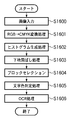
図16に示すのは、地紋画像を見つけるための前処理である。この前処理は、CPUの統括的な制御により実行される。S1600で画像データがRGBで入力される。次に、S1601で、RGB→CMの色変換を入力画像データに対して行う。これは、地紋画像は、シアン、マゼンタの色が用いられることが多いためである。そして、S1602では、CMYに色変換された後の画像データからヒストグラムを生成する。具体的には、Cのヒストグラムと、Mのヒストグラムと、Yのヒストグラムとを生成する。 FIG. 16 shows preprocessing for finding a tint block image. This preprocessing is executed under the overall control of the CPU. In S1600, image data is input in RGB. In step S1601, RGB → CM color conversion is performed on the input image data. This is because the tint block image often uses cyan and magenta colors. In step S1602, a histogram is generated from the image data after color conversion to CMY. Specifically, a C histogram, an M histogram, and a Y histogram are generated.
次に、S1603では、CMYに色変換された後の画像データに対して下地飛ばし処理を行う。この下地飛ばし処理とは、薄いデータを消す公知の処理である。地紋画像の背景部のドットは一つ一つが小さいため、スキャナで読み取ったときに薄いデータとして認識され、薄いデータであるが故に下地飛ばし処理により消されてしまう。ここで、スキャナで読み取った時に、背景部のドットが薄いデータとして認識される理由を以下に説明する。 In step S1603, background removal processing is performed on the image data that has undergone color conversion to CMY. This background removal process is a known process for erasing thin data. Since each dot in the background portion of the copy-forgery-inhibited pattern image is small, it is recognized as thin data when read by the scanner, and is erased by the background removal process because it is thin data. Here, the reason why the dots in the background portion are recognized as thin data when read by the scanner will be described below.
背景部のドットの大きさは約42um×42um(印刷解像度600dpiで1画素)程度であり、スキャナの読み取単位は42um×42um(スキャナ解像度600dpiで1ピクセル)程度である。必然的に起こりうる位相ずれにより、背景部のドットは4ピクセルに分散して読み取られることになる。そして、分散して読み取られるが故に、1ピクセルあたりのデータは、薄いデータとして読み取られる。 The size of dots in the background portion is about 42 um × 42 um (one pixel at a printing resolution of 600 dpi), and the reading unit of the scanner is about 42 um × 42 um (one pixel at a scanner resolution of 600 dpi). Due to the phase shift that may inevitably occur, the dots in the background portion will be read dispersedly over 4 pixels. Since data is read in a distributed manner, data per pixel is read as thin data.
一方、地紋画像の潜像部のドットは一つ一つが大きいため、スキャナで読み取ったときに濃いデータとして認識され、濃いデータであるが故に下地飛ばし処理による影響を受けない。ここで、スキャナで読み取った時に、潜像部のドットが濃いデータとして認識される理由を以下に説明する。 On the other hand, since the dots in the latent image portion of the tint block image are large one by one, they are recognized as dark data when read by the scanner and are not affected by the background removal process because they are dark data. Here, the reason why the dots in the latent image portion are recognized as dark data when read by the scanner will be described below.
背景部のドットの大きさは約126um×126um(印刷解像度600dpiで縦横3画素)程度であり、スキャナの読み取単位は42um×42um(スキャナ解像度600dpiで1ピクセル)程度である。そのため、潜像部のドットは、4×4(=16)ピクセルに分散して読み取られる可能性がある。しかし、たいして分散して読み取られないが故に、1ピクセルあたりのデータは、濃いデータとして読み取られる。 The size of the dots in the background portion is about 126 um × 126 um (printing resolution 600 dpi, 3 pixels vertically and horizontally), and the reading unit of the scanner is about 42 um × 42 um (scanner resolution 600 dpi, 1 pixel). Therefore, there is a possibility that the dots in the latent image portion are read in a dispersed manner of 4 × 4 (= 16) pixels. However, since data is not read in a distributed manner, the data per pixel is read as dark data.
以上説明したS1603での下地飛ばし処理により得られる画像データ上では、潜像部のドットは残存し、地紋画像の背景部のドットは消失していることになる。 In the image data obtained by the background removal process in S1603 described above, the dots in the latent image portion remain and the dots in the background portion of the tint block image disappear.
次に、S1604では、下地飛ばし処理が行われた後の画像データに対して、ブロックセレクション処理を行う。ブロックセレクション処理とは、画像データを文字列ブロックと、それ以外とに分割する処理である。言い換えると、ブロックセレクション処理とは、画像データから文字列ブロックを抜き出す処理である。 In step S1604, block selection processing is performed on the image data after the background removal processing is performed. The block selection process is a process of dividing image data into a character string block and other parts. In other words, the block selection process is a process for extracting a character string block from image data.
このブロックセレクション処理では、ある文字の近くに他の文字が存在しない場合には、その「ある文字」は一つの文字列ブロックとして抽出される。一方、ある文字の近くに他の文字が存在する場合には、その「ある文字」と「他の文字」とを含む文字列が一つの文字列ブロックとして抽出される。 In this block selection process, when there is no other character near a certain character, the “certain character” is extracted as one character string block. On the other hand, when another character exists near a certain character, a character string including the “certain character” and the “other character” is extracted as one character string block.
このように、ブロックセレクション処理は、お互いの距離が所定距離以内である複数の隣接した文字を含む文字列を文字列ブロックとして抜き出す処理である。例外として、所定距離以内に他の文字が存在しない場合には、その文字一つを文字列ブロックとして抜き出すことになる。地紋画像として付加された情報は、通常、「無効」や「VOID」や「複写禁止」といった文字列であることが多く、このように(文字単位でなく)文字列単位で抜き出すことが望ましい。 As described above, the block selection process is a process of extracting a character string including a plurality of adjacent characters whose distances are within a predetermined distance as a character string block. As an exception, when there is no other character within a predetermined distance, one character is extracted as a character string block. The information added as a copy-forgery-inhibited pattern image is usually a character string such as “invalid”, “VOID”, or “copy prohibited”, and it is desirable to extract the information in character string units (not character units).
本実施例では、「無効」や「VOID」や「複写禁止」といった文字列を図9で説明した画面上で設定することが可能であるが、これらのフォント情報を地紋文字記憶部に記憶する。この地紋文字記憶部には、ユーザが任意の文字列を地紋文字として登録することが可能である。 In this embodiment, it is possible to set character strings such as “invalid”, “VOID”, and “copy prohibited” on the screen described with reference to FIG. 9, but these font information is stored in the tint block character storage unit. . In this tint block character storage unit, the user can register an arbitrary character string as a tint block character.
原稿に含まれる文字列が、この地紋文字記憶部にあるかを比較し存在する場合には、地紋つきの原稿であると判断することも可能である。 If a character string included in a document exists in the copy-forgery-inhibited pattern character storage unit and is present, it can be determined that the document has a copy-forgery-inhibited pattern.
また、このブロックセレクション処理では、文字列ブロックの数を計算し、それをnとする。 In this block selection process, the number of character string blocks is calculated and is set to n.
次に、S1605では、このブロックセレクションにより文字列ブロックであると判定された領域に対して、文字の色を判別する処理を行う。この文字の色の判別結果は、後に用いられることになる。 In step S1605, processing for determining the color of the character is performed on the region determined to be a character string block by this block selection. This character color discrimination result will be used later.
次に、S1606では、このブロックセレクションにより文字列ブロックであると判定された領域に対して、文字認識処理と文字サイズ判断処理を施す。そして、得られた文字認識結果(文字コード)と文字サイズ判断結果と、文字色とを関連付けて、ブロック毎にRAM207に記憶して管理する。
In step S1606, character recognition processing and character size determination processing are performed on the area determined to be a character string block by this block selection. Then, the obtained character recognition result (character code), character size determination result, and character color are associated with each other and stored and managed in the
まず、ブロックの全てを読み込む(S2101)。S2102では、k=1とする。 First, all the blocks are read (S2101). In S2102, k = 1 is set.
次に、S2103では、k=nであるか否かを判定する。k=nであれば、S2201へ移行する。k=nでなければ、ステップ2104へ移行する。 Next, in S2103, it is determined whether k = n. If k = n, the process proceeds to S2201. If k = n is not the case, the process proceeds to Step 2104.
S2104では、k番目の文字列ブロックを対象とする。次に、S2105では、k番目の文字列ブロックに所定サイズ以上の文字が存在するか判定する。存在する場合には、S2106へ移行する。また存在しない場合には、S2108へ移行する。つまり、文字サイズが大きい文字列ブロックに対しては処理を継続する。これは、地紋画像として付加される文字列のサイズは、目立つように、大きくなっているはずだからである。 In S2104, the k-th character string block is targeted. Next, in S2105, it is determined whether or not a character of a predetermined size or more exists in the kth character string block. When it exists, it transfers to S2106. If it does not exist, the process proceeds to S2108. That is, processing is continued for a character string block having a large character size. This is because the size of the character string added as the copy-forgery-inhibited pattern image should be conspicuously large.
S2106では、k番目の文字列ブロックに含まれる文字の数が所定数以上であるかを判定する。所定数以上である場合には、S2108へ移行する。所定数より少ない場合には、S2107へ移行する。即ち、文字数の少ない文字列ブロックに対しては処理を継続する。これは、地紋画像として付加される文字列内の文字数は、「無効」や「複写禁止」や「VOID」のように少ないはずだからである。 In S2106, it is determined whether the number of characters included in the kth character string block is equal to or greater than a predetermined number. If the number is equal to or greater than the predetermined number, the process proceeds to S2108. If the number is smaller than the predetermined number, the process proceeds to S2107. That is, processing is continued for a character string block with a small number of characters. This is because the number of characters in the character string added as the copy-forgery-inhibited pattern image should be as small as “invalid”, “copy prohibited”, or “VOID”.
ステップ2107では、k番目の文字列ブロックを候補ブロックとし、続くS2108へ移行する。S2108では、kに1を加算してS2103へ移行する。
In
以上の処理により、候補ブロックが出揃い、その上でS2201へ移行する。 Through the above processing, candidate blocks are completed, and the process proceeds to S2201.
S2201では、S1602で生成されたヒストグラムと、各候補ブロックとを比較し、ヒストグラムにあったブロックを抽出する。このステップでの具体的な処理の流れは、以下のようである。 In S2201, the histogram generated in S1602 is compared with each candidate block, and a block that matches the histogram is extracted. The specific processing flow in this step is as follows.
まず、ヒストグラム上で所定値以上のカウント数を持つ色(CかMかY)を検索し、地紋画像の色を決定する。つまり、所定値以上のカウント数を持つのがCのみの時は、地紋画像の色はCと決定する。所定値以上のカウント数を持つのがMのみの時は、地紋画像の色はMと決定する。所定値以上のカウント数を持つのがYのみの時は、地紋画像の色はYと決定する。所定値以上のカウント数を持つのがCMY全ての時は、地紋画像の色をKと決定する。残りの時は、処理を中断する。 First, a color (C, M, or Y) having a count number equal to or greater than a predetermined value is searched on the histogram to determine the color of the tint block image. That is, when only C has a count number equal to or greater than a predetermined value, the color of the tint block image is determined as C. When only M has a count number equal to or greater than a predetermined value, the color of the tint block image is determined as M. When only Y has a count number equal to or greater than a predetermined value, the color of the tint block image is determined as Y. When all CMY have a count number equal to or greater than a predetermined value, the color of the tint block image is determined as K. The process is interrupted for the remaining time.
そして、決定された地紋画像の色と同じ色のブロックを候補ブロックの中から抽出する。このステップで、ヒストグラムにあったブロックを抽出する理由は、ヒストグラムを見れば地紋画像の色を判定できるからである。言い換えると、地紋画像はヒストグラムに大きな影響を与える画像だからである。地紋画像は、一般に、紙の全面に合成されている。そして、地紋画像の色は、全面で略一律(薄いC又は薄いM又は薄いY又は薄いK)である。つまり、地紋画像は、全面に存在する同じ色の画像である。従って、ヒストグラムに大きな影響を与える。 Then, a block having the same color as the determined tint block image color is extracted from the candidate blocks. The reason for extracting a block in the histogram in this step is that the color of the tint block image can be determined by looking at the histogram. In other words, the tint block image is an image that greatly affects the histogram. A copy-forgery-inhibited pattern image is generally synthesized on the entire surface of paper. The color of the tint block image is substantially uniform over the entire surface (thin C or thin M, thin Y or thin K). That is, the copy-forgery-inhibited pattern image is an image of the same color existing on the entire surface. Therefore, the histogram is greatly affected.
以上の処理が終了すると、S2202の処理へ移る。 When the above process ends, the process proceeds to S2202.
まず、S2202では、S2201で抽出された候補ブロック(ヒストグラムに合った文字列ブロック)を全て読込む。次に、S2203では、読み込んだブロックのうち一つ目のブロックを対象ブロックとする。 First, in S2202, all candidate blocks (character string blocks matching the histogram) extracted in S2201 are read. In step S2203, the first block among the read blocks is set as a target block.
次に、S2204では、候補ブロックがまだ残っているか否かを判定する。判定の結果、候補ブロックが残っていなければS2301へ移行する。一方、判定の結果、候補ブロックが残っていれば、残っている候補ブロックから一つを選択してS2205へ移行する。 Next, in S2204, it is determined whether candidate blocks still remain. If no candidate block remains as a result of the determination, the process proceeds to S2301. On the other hand, if the candidate block remains as a result of the determination, one is selected from the remaining candidate blocks, and the process proceeds to S2205.
S2205では、同一の文字列が存在する候補ブロックが他の候補ブロックに存在するか否かを判定する。判定の結果、存在すればS2206へ移行する。一方、判定の結果、存在しなければ、S2204に戻る。尚、このステップの処理を言い換えると、他の候補ブロックと同じ文字列を持つ候補ブロックを検索する処理である。 In step S2205, it is determined whether a candidate block having the same character string exists in another candidate block. As a result of the determination, if it exists, the process proceeds to S2206. On the other hand, if it does not exist as a result of the determination, the process returns to S2204. In other words, the process of this step is a process of searching for a candidate block having the same character string as another candidate block.
S2206では、対象とした候補ブロックと、その対象とした候補ブロックと同一の文字列を有する「他の候補ブロック」とを最終候補ブロックとする。この処理が終了すると、S2204に戻る。 In S2206, the target candidate block and “other candidate block” having the same character string as the target candidate block are set as final candidate blocks. When this process ends, the process returns to S2204.
以上の処理により、最終候補ブロックが出揃う。そして、S2204からS2301へと移行する。 Through the above processing, final candidate blocks are prepared. Then, the process proceeds from S2204 to S2301.
S2301では、全ての最終候補ブロックの位置関係の認識を行い、認識の結果として位置テーブルを作成する。そして、S2302では、作成された位置テーブルに基づいて、最終候補ブロックの配置が規則的であるか否かを判定する。具体的には、最終候補ブロックの位置として、次式が成立するような第1の文字列、第2の文字列、第3の文字列、第4の文字列の4つのブロックが存在する場合に規則的であると判定する。 In S2301, the positional relationship of all final candidate blocks is recognized, and a position table is created as a result of recognition. In step S2302, it is determined whether the final candidate block is regularly arranged based on the created position table. Specifically, when there are four blocks of the first character string, the second character string, the third character string, and the fourth character string that satisfy the following expression as the position of the final candidate block: Is determined to be regular.
(X2-X1,Y2-Y1)≒(X4-X3,Y4-Y3)
尚、上記式は、第1のブロック(X1,Y1)と第2のブロック(X2,Y2)のx、y方向の各距離と、第3のブロック(X3,Y3)と第4のブロック(X4,Y4)のx、y方向の各距離とが略同一であることを示している。また、このように規則的であるか否かを判定する理由は、通常、地紋画像の文字列は規則的に配列されているからである。
(X2-X1, Y2-Y1) ≒ (X4-X3, Y4-Y3)
It should be noted that the above formula is obtained by calculating the distance between the first block (X1, Y1) and the second block (X2, Y2) in the x and y directions, the third block (X3, Y3), and the fourth block ( This shows that the distances in the x and y directions of X4, Y4) are substantially the same. The reason why it is determined whether or not it is regular in this way is that the character strings of the copy-forgery-inhibited pattern image are normally arranged regularly.
判定の結果、規則的に配列されている場合にはS2303(地紋として判定)へ移行し、規則的に配列されていない場合にはS2304(非地紋として判定)へ移行することになる。 If the result of the determination is that they are regularly arranged, the process proceeds to S2303 (determined as a background pattern), and if they are not regularly arranged, the process proceeds to S2304 (determined as a non-background pattern).
<例示の説明>
以下では、S1603からS2304までの処理について、例示する。
<Description of examples>
Hereinafter, the processing from S1603 to S2304 will be exemplified.
S1603における下地飛ばし処理により、図18に示す画像データが得られたとする。ここで、この画像データは、「複製」の部分がシアン、「住所・名前」の部分が黒、「住民票」の部分が赤となっている。すると、S1604では、ブロックセレクション処理により、図19に示すように、文字列ブロック1〜9が抽出される。 Assume that the image data shown in FIG. 18 is obtained by the background removal process in S1603. Here, in this image data, the “duplicate” portion is cyan, the “address / name” portion is black, and the “resident card” portion is red. Then, in S1604, the character string blocks 1 to 9 are extracted by the block selection process as shown in FIG.
続いて、S1605では、文字色判定処理により、文字列ブロック2〜4と6〜9は、シアンと認識される。また、文字列ブロック1は、黒(シアン+赤)と認識される。更に、文字列ブロック5も、黒と認識される。
In step S1605, the character string blocks 2 to 4 and 6 to 9 are recognized as cyan by the character color determination process. The
S1606では、OCR処理が行われ、文字列ブロック1は「複製 住民票」と認識され、文字列ブロック2〜4と6〜9は「複製」と認識され、文字列ブロック5は「神奈川県川崎市××区 山田太郎」と認識される。
In S1606, OCR processing is performed,
次に、S2101からS2107の処理の結果、文字列ブロック1〜4と6〜9が候補ブロックとなる。文字列ブロック5については、S2105(所定サイズ以上の文字か?)での処理により候補ブロックからはずれてしまう。
Next, as a result of the processing from S2101 to S2107, character string blocks 1 to 4 and 6 to 9 become candidate blocks. The
次に、S2201の処理の結果、文字列ブロック1が候補ブロックからはずれてしまう。これは、ヒストグラムに合った色がシアンであるのに対して、文字列ブロック1は黒だからである。
Next, as a result of the processing in S2201, the
残った文字列ブロック2〜4と6〜9に対して、S2201〜S2301の処理により文字列が一致しているか否かが判定されるが、全ての文字列ブロックが残ることになる。なぜなら、全ての文字列ブロックには、同じ「複製」という文字列が含まれているからである。 Whether or not the character strings match the remaining character string blocks 2 to 4 and 6 to 9 is determined by the processing of S2201 to S2301, but all the character string blocks remain. This is because all the character string blocks include the same character string “duplicate”.
こうして、全ての文字列ブロックに対してS2301で位置(座標)認識を行い、その処理結果を図20に示すようにテーブル化する。 In this way, position (coordinates) recognition is performed in S2301 for all character string blocks, and the processing results are tabulated as shown in FIG.
次に、S2302で、各ブロックの配置が等間隔であるか否かをX方向、Y方向で夫々判定する。ここで、「複製」という同一の文字列を持つブロックがX方向、Y方向に規則的(周期的)に現れており、規則性(周期性)があると判断した場合に、原稿画像に地紋画像が付加されていると判定する(S2303)。また、規則性(周期性)がないと判断した場合は地紋画像なしと判定する(S2304)。 Next, in S2302, it is determined in the X direction and the Y direction whether or not the arrangement of each block is equally spaced. Here, blocks having the same character string “Duplicate” appear regularly (periodically) in the X direction and Y direction, and when it is determined that there is regularity (periodicity), the background pattern is added to the original image. It is determined that an image has been added (S2303). If it is determined that there is no regularity (periodicity), it is determined that there is no copy-forgery-inhibited pattern image (S2304).
また、同一テキストの周期性を判定するだけでなく、地紋画像に含まれることが多い、例えば複製、複写、禁止等の文字列を予めメモリ内に保持し、その文字列との比較により、地紋画像の有無を判定するようにしても良い。 In addition to determining the periodicity of the same text, a character string that is often included in a copy-forgery-inhibited pattern image, for example, a copy, copy, or prohibition character string is stored in memory in advance, and compared with the character string, You may make it determine the presence or absence of an image.
尚、図21〜図23に示すフローチャートからわかるように、規則(周期)的に文字列が配置されているか否かの周期性判定の前に、本実施形態では、「所定の文字サイズ以上であるか」の判定や「所定の文字数以下であるか」の判定を行っている。これは、周期性判定の前に、対象とする文字列(文字ブロック)を減らすことを目的として行っている。このように周期性判定の処理を後回しにするのは、他の処理に比べて周期性判定の処理には非常に長い時間がかかるからである。 As can be seen from the flowcharts shown in FIG. 21 to FIG. 23, in this embodiment, before the periodicity determination of whether or not the character strings are regularly (periodically) arranged, It is determined whether or not there is a certain number of characters or less. This is performed for the purpose of reducing target character strings (character blocks) before periodicity determination. The reason why the periodicity determination process is postponed in this way is that the periodicity determination process takes a very long time compared to other processes.
例えば、100の文字列が存在した場合に、周期性判定をする必要があるのは、100C4=100×99×98×97÷(4×3×2×1)=3922125となり、非常に計算量が多いからである。 For example, when there are 100 character strings, it is necessary to determine the periodicity because 100C4 = 100 × 99 × 98 × 97 ÷ (4 × 3 × 2 × 1) = 3922125, which is a very computational complexity. Because there are many.
以上、電子ファイル化、地紋判定の処理を専用のブロックで行う構成としたが、CPU203を用いて同様の処理を行っても良い。
As described above, the processing for making an electronic file and determining the tint block is performed in a dedicated block. However, the
[地紋判定結果による処理の制限1]
次に、上述した地紋判定処理の結果に応じて、デジタル複合機の機能を変更する処理について、図24〜図27を用いて説明する。
[
Next, processing for changing the function of the digital multi-function peripheral in accordance with the result of the tint block determination processing described above will be described with reference to FIGS.
地紋画像が存在する場合、下地飛ばしを施さないための設定を行う。そして、濃度補正機能を所定のレベルに設定する。この処理について、図24で説明する。まず、ステップS2401において、上述した地紋判定処理の結果を確認する。ここで、原稿画像に地紋画像がない場合は、ステップS2405へ処理を進め、通常処理を行う。この通常処理では、S1603における下地飛ばし処理を行った後の画像データを印刷出力する。 When a copy-forgery-inhibited pattern image exists, a setting is made so that background removal is not performed. Then, the density correction function is set to a predetermined level. This process will be described with reference to FIG. First, in step S2401, the result of the above-mentioned tint block determination process is confirmed. If there is no copy-forgery-inhibited pattern image in the original image, the process advances to step S2405 to perform normal processing. In this normal process, the image data after the background removal process in S1603 is printed out.
一方、原稿画像に地紋画像がある場合は、ステップS2402へ処理を進め、下地飛ばしの処理をキャンセルし、ステップS2403において、濃度補正テーブルの値を地紋画像が消失しないようなレベルに設定する。そして、ステップS2404において、図25に示すようなメッセージ画面2501を液晶操作パネル601に表示し、ユーザに通知を行う。
On the other hand, if there is a copy-forgery-inhibited pattern image in the original image, the process proceeds to step S2402, the background removal process is canceled, and in step S2403, the value of the density correction table is set to a level such that the copy-forgery-inhibited pattern image is not lost. In step S2404, a
ここで、ユーザがOKタブ2502を押下すると、コピーを継続し、ユーザがキャンセルタブ2503を押下すると、コピーをキャンセルする。尚、コピーを継続する場合には、S1603の下地飛ばし処理を行う前の画像データを印刷出力する。
Here, when the user presses the
[地紋判定結果による処理の制限2]
図26は、地紋画像が存在する場合、電子ファイル化をキャンセルする処理を示すフローチャートである。このフローチャートの処理が始まる前に、ユーザにより電子ファイル化の指示があったことは言うまでもない。
[
FIG. 26 is a flowchart showing a process for canceling the electronic file creation when the copy-forgery-inhibited pattern image exists. Needless to say, the user gave an instruction to make an electronic file before the processing of this flowchart started.
このフローチャートでは、まず、ステップS2601において、上述した地紋判定処理の結果を確認する。ここで、原稿画像に地紋画像がない場合、ステップS2604へ処理を進め、電子ファイル化を許可し、上述した電子ファイル化の処理に従って電子ファイル化を行う。 In this flowchart, first, in step S2601, the result of the background pattern determination process described above is confirmed. If there is no copy-forgery-inhibited pattern image in the original image, the process advances to step S2604 to permit electronic file conversion, and electronic file conversion is performed in accordance with the electronic file conversion process described above.
一方、原稿画像に地紋画像がある場合、ステップS2602へ処理を進め、電子ファイル化を禁止する。そして、ステップS2603において、図27に示すようなメッセージ画面2701を液晶操作パネル601に表示し、ユーザに通知を行う。ここで、ユーザがOKタブ2701を押下すると、電子ファイル化をキャンセルする。
On the other hand, if there is a copy-forgery-inhibited pattern image in the document image, the process proceeds to step S2602, and the electronic file creation is prohibited. In step S2603, a
[地紋判定結果による処理の制限3]
地紋判定結果による処理の制限2では、地紋画像が存在する場合に、電子ファイル化をキャンセルする処理について開示した。この例では、地紋画像が存在する場合であっても地紋画像が存在しない場合であっても電子ファイル化を行う。しかしながら、地紋画像が存在する場合には、電子ファイルとして地紋属性を付けることにする。そして、地紋画像が存在しない場合には、電子ファイルとして非地紋属性を付けることにする。このように、属性(ヘッダ情報)として地紋又は非地紋という情報を付けることで、電子ファイルの管理が楽になる。
[
In the
例えば、重要な文書と重要でない文書を区別したい時には、地紋属性あり=重要、地紋属性なし=重要でないとすることで容易に管理できる。また、例えば、機密な文書と機密でない文書を区別したい時には、地紋属性あり=機密、地紋属性なし=機密でないとすることで容易に管理できる。 For example, when it is desired to distinguish an important document from an unimportant document, it can be easily managed by setting the background pattern attribute = important and the background pattern attribute = not important. Also, for example, when it is desired to distinguish between a confidential document and a non-confidential document, it can be easily managed by assuming that the copy-forgery-inhibited pattern attribute = confidential and no copy-forgery-inhibited pattern attribute = non-confidential.
また、地紋属性ありの場合には表示のみ可、地紋属性なしの場合には印刷出力可とすることで、機密や重要な情報の流出が抑止できる。そのため、地紋属性ありなしの情報に応じて、画像に対する処理方法を切り換える切り換え手段があるのが望ましい。 In addition, only the display is possible when the copy-forgery-inhibited pattern attribute is provided, and printout is possible when the copy-forgery-inhibited pattern attribute is not provided, thereby preventing leakage of confidential information and important information. For this reason, it is desirable to have a switching means for switching the processing method for an image in accordance with information with or without a tint block attribute.
[地紋判定結果による処理の制限4]
地紋の付加された原本をコピーした際に、本来は「VOID」などの文字列が浮かび上がることになる。しかし、悪意のあるユーザがもし原本をスキャンして得られた画像上に再度、地紋と同じ地紋(各ドットの配置位置が同じ地紋)を合成したとすると、再度、地紋の付加された原本が作成されてしまうことになる。
[
When you copy the original with the copy-forgery-inhibited pattern, you will naturally see a character string such as “VOID”. However, if a malicious user scans the original, the same copy-forgery-inhibited pattern (the same background pattern in which each dot is arranged) is synthesized again on the image obtained by scanning the original. It will be created.
図33に示すフローチャートは、「悪意のあるユーザが地紋の付加された原本をコピーし、地紋の付加された原本を作成しようとする」のを防止するための処理である。 The flowchart shown in FIG. 33 is a process for preventing “a malicious user from copying an original with a tint block and trying to create an original with a tint block”.
具体的には、図33は、原稿が地紋画像であると判断した場合、さらに地紋付加設定がなされている場合に、地紋付加設定を変更する処理を示すフローチャートである。 Specifically, FIG. 33 is a flowchart showing processing for changing the copy-forgery-inhibited pattern setting when it is determined that the document is a copy-forgery-inhibited pattern image and the copy-forgery-inhibited pattern addition setting is made.
まず、ステップS3301で、原稿画像に地紋画像があるか否かを判定し、原稿画像に地紋画像がある場合にはステップS3302へ処理を進め、下地処理をキャンセルする。そして、ステップS3303で、濃度補正テーブルの変更を行い、ステップS3304で図25に示すようなメッセージを表示する。 First, in step S3301, it is determined whether or not there is a copy-forgery-inhibited pattern image in the document image. If the copy-forgery-inhibited pattern image exists in the document image, the process proceeds to step S3302, and the background processing is canceled. In step S3303, the density correction table is changed, and a message as shown in FIG. 25 is displayed in step S3304.
その後、ステップS3305で、装置の設定に地紋付加の設定が行われているか否かを判断し、地紋付加設定が行われている場合には、例えば図34に示すような設定変更要望画面3401を液晶操作パネル601に表示し、ユーザに通知を行う。
Thereafter, in step S3305, it is determined whether or not the setting for adding a tint block is set in the setting of the apparatus. If the setting for adding a tint block is set, for example, a setting
ユーザによりOKタブ3402が押下されると、地紋付加設定が取り消されてコピーを継続し、キャンセルタブ3403が押下されると、コピーをキャンセルする。
If the
一方、ステップS3301で原稿画像に地紋画像がない場合にはステップS3307へ処理を進め、通常の処理を行う。 On the other hand, if there is no copy-forgery-inhibited pattern image in the original image in step S3301, the process proceeds to step S3307 to perform normal processing.
第1の実施形態によれば、原稿中に付加された地紋の文字列を判別し、原稿が文字列を含む地紋を有することを検出し、原稿画像に対する下地除去処理や濃度補正処理、或いは電子ファイル化をキャンセルできる。従って、地紋を含む原稿画像の好ましくない複製を抑制することができる。 According to the first embodiment, a character string of a background pattern added to a document is determined, it is detected that the document has a background pattern including a character string, and background removal processing, density correction processing, or electronic processing is performed on the document image. File creation can be canceled. Accordingly, it is possible to suppress undesired duplication of a document image including a background pattern.
[第2の実施形態]
次に、図面を参照しながら本発明に係る第2の実施形態について詳細に説明する。第2の実施形態は、第1の実施形態で説明した地紋画像の生成処理において、地紋画像を構成するドットの配置の位置を制御する。即ち、地紋画像のドットの配置によって地紋画像が付加されたことを識別する。
[Second Embodiment]
Next, a second embodiment according to the present invention will be described in detail with reference to the drawings. In the second embodiment, in the tint block image generation process described in the first embodiment, the positions of the dots constituting the tint block image are controlled. That is, it is identified that the copy-forgery-inhibited pattern image has been added by the arrangement of dots in the copy-forgery-inhibited pattern image.
尚、それ以外の基本的な地紋付加処理に関しては、第1の実施形態と同様であり、図11で説明した通りである。また、第2の実施形態では、第1の実施形態で説明した地紋付き原稿の認識処理について、上述した地紋画像のドット位置を検出することによって地紋画像の認識を行う。 The other basic tint block addition processing is the same as that of the first embodiment, as described with reference to FIG. In the second embodiment, the background pattern image is recognized by detecting the dot position of the background pattern image described above in the recognition process of the background pattern original document described in the first embodiment.
まず、第2の実施形態における地紋画像の生成処理について説明する。図28は、地紋画像を構成するドットの構成を示す図である。図28に示すように、小ドットの集まりと大ドットの集まりで、人間の見た目の濃度が等しくなるように構成されている。 First, a tint block image generation process in the second embodiment will be described. FIG. 28 is a diagram illustrating a configuration of dots that form a copy-forgery-inhibited pattern image. As shown in FIG. 28, the density of human appearance is the same in a group of small dots and a group of large dots.
地紋画像を付加する場合、図29に示すように、小ドットの形成位置を移動させる処理を行う。ここで、ドットを移動させる処理は4種類に分類される。尚、図29に示す点線の交点が小ドットの位置の基準点である。 When a copy-forgery-inhibited pattern image is added, as shown in FIG. 29, a process of moving the small dot formation position is performed. Here, the process of moving the dots is classified into four types. Note that the intersection of the dotted lines shown in FIG. 29 is the reference point for the position of the small dot.
図29において、2901〜2904はドットを移動させる4種類の配置位置である。即ち、ドット2901は基準点より右上に移動したドットで、ドット2902〜2904はそれぞれ基準点より、右下、左下、左上に移動したドットである。
In FIG. 29, 2901 to 2904 are four types of arrangement positions for moving dots. That is, the
図30は、小ドットの部分だけを抜き出した図である。原稿画像に地紋画像が含まれる場合、ドットの基準点からの配置位置を、水平方向、垂直方向共に、右上、右下、左下、左上という順でドットを形成する。図30に示す例では、水平方向に、ドット3001、3005、3006、3007が、垂直方向に、ドット3001、3002、3003、3004が形成されている。これにより、地紋画像が付加された原稿画像と、地紋画像が付加されていない原稿画像とを区別することができる。
FIG. 30 is a diagram in which only small dot portions are extracted. When a copy-forgery-inhibited pattern image is included in the document image, dots are formed in the order of upper right, lower right, lower left, and upper left in the horizontal and vertical directions from the reference point of the dot. In the example shown in FIG. 30,
次に、原稿画像に含まれる地紋画像を認識する認識処理について、図31を用いて説明する。この認識処理は、第1の実施形態と同様に、スキャナ画像処理部216の地紋判定部307で行われる。
Next, recognition processing for recognizing a copy-forgery-inhibited pattern image included in a document image will be described with reference to FIG. This recognition process is performed by the tint
図31は、地紋画像を認識する認識処理を説明するための図である。図31に示すように、小ドットの配置に対して水平方向に対応した4つのウインドウ3101と、垂直方向に対応した4つのウインドウ3103とを概念的に配置している。
FIG. 31 is a diagram for explaining recognition processing for recognizing a copy-forgery-inhibited pattern image. As shown in FIG. 31, four
ウインドウ3101は4つの矩形の集まりであり、点線の交点で示される基準点を中心とし、1つの矩形に1つのドットが収まるサイズとなっている。1つの矩形は4つの部分に分けられ、該当領域の画素の平均濃度を検出する。3102は各領域の平均濃度の検出結果であり、この結果により、3102の最も左の領域に含まれるドットが矩形内の右上の位置に存在していることがわかる。また同様に、4つの隣接したドットは右上、右下、左下、左上という順序で形成されていることが認識できる。
The
一方、ウインドウ3103と平均濃度3104の結果より、垂直方向にもドットが右上、右下、左下、左上という順序で形成されていることが認識できる。このように、右上、右下、左下、左上というドットパターンが認識されたことにより、この原稿画像には地紋画像が含まれていることがわかる。
On the other hand, it can be recognized from the results of the
次に、原稿の読み取り誤差により、ドットの位置を検出するためのウインドウが原稿とずれてしまった場合の処理について、図32を用いて説明する。 Next, processing when the window for detecting the dot position is shifted from the original due to an original reading error will be described with reference to FIG.
図32は、図31に示すドットパターンの変形例を示す図である。ここで、ウインドウ3201は本来の位置よりも水平方向に矩形のサイズ半分右にずれている。この場合、平均濃度結果3202は2番目の矩形領域で2つのドットを捉えているため、矩形内で2箇所濃度が現れる部分が存在する。このような場合、ウインドウを水平方向に半分ずらして再度小ドットの濃度を検出すれば良い。
FIG. 32 is a diagram showing a modification of the dot pattern shown in FIG. Here, the
また、3203は垂直方向のウインドウであり、水平方向に1/4だけずれている場合の例である。この場合、2つの矩形において、2箇所の濃度を持った領域が検出され、その濃度値は3202の濃度値よりも薄くなる。従って、各矩形の濃度値を持った領域情報と、その濃度値により、ウインドウの水平方向のずれ、垂直方向のずれを検出することが可能である。
このようにして、原稿画像に地紋画像が含まれるか否かを認識した後の処理は、第1の実施形態と同様であり、図24〜図27を用いて説明した通りである。 Thus, the processing after recognizing whether or not the copy-forgery-inhibited pattern image is included in the document image is the same as that in the first embodiment, and is as described with reference to FIGS.
第2の実施形態では、地紋画像を付加した場合、小ドットの配置として、右上、右下、左下、左上としたが、この配置に限定されるものではない。 In the second embodiment, when the copy-forgery-inhibited pattern image is added, the small dots are arranged in the upper right, lower right, lower left, and upper left. However, the arrangement is not limited to this.
また、ドットの位置を検出するためのウインドウとして、1×4及び4×1のサイズを例に挙げたが、2×2などの正方形のウインドウや異なるサイズのウインドウを用いてもかまわない。また、配置のパターンも、他にもいくつかのパターンがあり、そのパターンを、例えば地紋画像に含まれる文字列の種類によって使い分けるようにしても良い。 In addition, as the window for detecting the position of the dot, the sizes of 1 × 4 and 4 × 1 are given as an example, but a square window such as 2 × 2 or a window of a different size may be used. In addition, there are some other patterns of arrangement, and these patterns may be selectively used depending on the type of character string included in the copy-forgery-inhibited pattern image, for example.
また、原稿の読み取り時に、ユーザが原稿の向きを90度、180度、270度に回転して置くことも考えられるが、その場合、回転角度に応じて、右上、右下、左下、左上等のパターンを4通り用意してそれを検出するようにすれば良い。 It is also conceivable that the user rotates the orientation of the document by 90 degrees, 180 degrees, and 270 degrees when reading the document. In this case, depending on the rotation angle, the upper right, lower right, lower left, upper left, etc. The four patterns may be prepared and detected.
尚、本発明は複数の機器(例えば、ホストコンピュータ,インターフェース機器,リーダ,プリンタなど)から構成されるシステムに適用しても、1つの機器からなる装置(例えば、複写機,ファクシミリ装置など)に適用しても良い。 Even if the present invention is applied to a system composed of a plurality of devices (for example, a host computer, an interface device, a reader, a printer, etc.), it is applied to an apparatus (for example, a copier, a facsimile machine, etc.) composed of a single device. It may be applied.
また、前述した実施形態の機能を実現するソフトウェアのプログラムコードを記録した記録媒体を、システム或いは装置に供給し、そのシステム或いは装置のコンピュータ(CPU若しくはMPU)が記録媒体に格納されたプログラムコードを読出し実行する。これによっても、本発明の目的が達成されることは言うまでもない。 In addition, a recording medium in which a program code of software for realizing the functions of the above-described embodiments is recorded is supplied to the system or apparatus, and the computer (CPU or MPU) of the system or apparatus stores the program code stored in the recording medium. Read and execute. It goes without saying that the object of the present invention can also be achieved by this.
この場合、コンピュータ読み取り可能な記録媒体から読出されたプログラムコード自体が前述した実施形態の機能を実現することになり、そのプログラムコードを記憶した記録媒体は本発明を構成することになる。 In this case, the program code itself read from the computer-readable recording medium realizes the functions of the above-described embodiments, and the recording medium storing the program code constitutes the present invention.
このプログラムコードを供給するための記録媒体として、例えばフレキシブルディスク,ハードディスク,光ディスク,光磁気ディスク,CD−ROM,CD−R,磁気テープ,不揮発性のメモリカード,ROMなどを用いることができる。 As a recording medium for supplying the program code, for example, a flexible disk, a hard disk, an optical disk, a magneto-optical disk, a CD-ROM, a CD-R, a magnetic tape, a nonvolatile memory card, a ROM, or the like can be used.
また、コンピュータが読出したプログラムコードを実行することにより、前述した実施形態の機能が実現されるだけでなく、次の場合も含まれることは言うまでもない。即ち、プログラムコードの指示に基づき、コンピュータ上で稼働しているOS(オペレーティングシステム)などが実際の処理の一部又は全部を行い、その処理により前述した実施形態の機能が実現される場合である。 In addition, by executing the program code read by the computer, not only the functions of the above-described embodiments are realized, but also the following cases are included. That is, based on the instruction of the program code, an OS (operating system) running on the computer performs part or all of the actual processing, and the functions of the above-described embodiments are realized by the processing. .
更に、記録媒体から読出されたプログラムコードがコンピュータに挿入された機能拡張ボードやコンピュータに接続された機能拡張ユニットに備わるメモリに書込む。その後、そのプログラムコードの指示に基づき、その機能拡張ボードや機能拡張ユニットに備わるCPUなどが実際の処理の一部又は全部を行い、その処理により前述した実施形態の機能が実現される場合も含まれることは言うまでもない。 Further, the program code read from the recording medium is written in a memory provided in a function expansion board inserted into the computer or a function expansion unit connected to the computer. After that, based on the instruction of the program code, the CPU of the function expansion board or function expansion unit performs part or all of the actual processing, and the function of the above-described embodiment is realized by the processing. Needless to say.
101 スキャナ部
102 プリンタ部
103 操作部
104 LAN
105 公衆回線
110 原稿フィーダ
111 トレイ
120 用紙カセット
121 用紙カセット
122 用紙カセット
123 用紙カセット
124 排紙トレイ
200 コントローラユニット
201 システムバス
202 イメージバス
203 CPU
204 操作部I/F
205 ネットワークI/F
206 モデム
207 RAM
208 ROM
209 HDD
210 イメージバスI/F
211 圧縮部
212 圧縮部
213 伸張部
214 画像変換部
215 ラスターイメージプロセッサ(RIP)
216 スキャナ画像処理部
217 プリンタ画像処理部
218 スキャナI/F
219 プリンタI/F
101
105
204 Operation unit I / F
205 Network I / F
206
208 ROM
209 HDD
210 Image bus I / F
211
216 Scanner
219 Printer I / F
Claims (5)
前記読取りにより得られた原稿画像から色のヒストグラムを生成し、所定値以上のカウント数を持つ色がどの色か判定する色判定手段と、
前記読取りにより得られた原稿画像に対して下地飛ばし処理を行う下地飛ばし処理手段と、
前記下地飛ばし処理により得られた原稿画像の中から、前記色判定手段の判定結果の色と同じ色を持ち、かつ、規則的に配置されている複数の文字列が存在するか判定する判定手段と、
前記判定手段での判定結果に応じた処理を前記原稿画像に対して施す処理手段とを有することを特徴とする画像処理装置。 Reading means for reading a document;
A color determination unit that generates a color histogram from a document image obtained by the reading and determines which color has a count number equal to or greater than a predetermined value;
Background removal processing means for performing background removal processing on the document image obtained by the reading;
Judgment means for judging whether or not there are a plurality of regularly arranged character strings having the same color as the judgment result color of the color judgment means from the document image obtained by the background removal process When,
An image processing apparatus comprising: processing means for performing processing on the original image according to a determination result by the determination means.
前記判定手段は、前記下地飛ばし処理により得られた原稿画像の中から、前記色判定手段の判定結果の色と同じ色を持ち、かつ、規則的に配置されている複数の文字列が存在するか判定し、
前記色判定手段が、所定値以上のカウント数を持つ色がC,M,Yの全てであると判定した場合には、
前記判定手段は、前記下地飛ばし処理により得られた原稿画像の中から、黒色を持ち、かつ、規則的に配置されている複数の文字列が存在するか判定することを特徴とする請求項2に記載の画像処理装置。 When the color determination means determines that the color having a count number equal to or greater than a predetermined value is one of C, M, and Y,
The determination means includes a plurality of character strings that have the same color as the determination result of the color determination means and are regularly arranged from the document image obtained by the background removal process. Determine whether
When the color determination means determines that the colors having a count number equal to or greater than a predetermined value are all of C, M, and Y,
Said determination means, said out of the background removal obtained original image by processing, it has a black and claim 2, characterized in that to determine whether a plurality of character strings are arranged regularly present An image processing apparatus according to 1.
前記読取りにより得られた原稿画像から色のヒストグラムを生成し、所定値以上のカウント数を持つ色がどの色か判定する色判定工程と、
前記読取りにより得られた原稿画像に対して下地飛ばし処理を行う下地飛ばし処理工程と、
前記下地飛ばし処理により得られた原稿画像の中から、前記色判定工程の判定結果の色と同じ色を持ち、かつ、規則的に配置されている複数の文字列が存在するか判定する判定工程と、
前記判定工程における判定結果に応じた処理を前記原稿画像に対して施す処理工程とを有することを特徴とする画像処理装置の処理方法。 A reading process for reading a document;
A color determination step for generating a color histogram from a document image obtained by the reading and determining which color has a count number equal to or greater than a predetermined value;
A background removal processing step of performing background removal processing on the document image obtained by the reading;
A determination step of determining whether or not there are a plurality of character strings that have the same color as the determination result of the color determination step and are regularly arranged from the document image obtained by the background removal processing When,
And a processing step of performing processing on the original image according to the determination result in the determination step.
原稿を読取る読取工程と、
前記読取りにより得られた原稿画像から色のヒストグラムを生成し、所定値以上のカウント数を持つ色がどの色か判定する色判定工程と、
前記読取りにより得られた原稿画像に対して下地飛ばし処理を行う下地飛ばし処理工程と、
前記下地飛ばし処理により得られた原稿画像の中から、前記色判定工程の判定結果の色と同じ色を持ち、かつ、規則的に配置されている複数の文字列が存在するか判定する判定工程と、
前記判定工程における判定結果に応じた処理を前記原稿画像に対して施す処理工程とを実行させるためのプログラム。 The computer includes the processing method of the image processing apparatus,
A reading process for reading a document;
A color determination step for generating a color histogram from a document image obtained by the reading and determining which color has a count number equal to or greater than a predetermined value;
A background removal processing step of performing background removal processing on the document image obtained by the reading;
A determination step of determining whether or not there are a plurality of character strings that have the same color as the determination result of the color determination step and are regularly arranged from the document image obtained by the background removal processing When,
A program for executing a processing step of performing processing on the original image according to a determination result in the determination step .
Priority Applications (3)
| Application Number | Priority Date | Filing Date | Title |
|---|---|---|---|
| JP2007104216A JP4617328B2 (en) | 2006-07-20 | 2007-04-11 | Image processing apparatus and processing method thereof |
| US11/765,604 US7742197B2 (en) | 2006-07-20 | 2007-06-20 | Image processing apparatus that extracts character strings from a image that has had a light color removed, and control method thereof |
| CN2007101366941A CN101110890B (en) | 2006-07-20 | 2007-07-20 | Image processing apparatus and control method thereof |
Applications Claiming Priority (2)
| Application Number | Priority Date | Filing Date | Title |
|---|---|---|---|
| JP2006198708 | 2006-07-20 | ||
| JP2007104216A JP4617328B2 (en) | 2006-07-20 | 2007-04-11 | Image processing apparatus and processing method thereof |
Publications (3)
| Publication Number | Publication Date |
|---|---|
| JP2008048378A JP2008048378A (en) | 2008-02-28 |
| JP2008048378A5 JP2008048378A5 (en) | 2008-12-04 |
| JP4617328B2 true JP4617328B2 (en) | 2011-01-26 |
Family
ID=38971576
Family Applications (1)
| Application Number | Title | Priority Date | Filing Date |
|---|---|---|---|
| JP2007104216A Expired - Fee Related JP4617328B2 (en) | 2006-07-20 | 2007-04-11 | Image processing apparatus and processing method thereof |
Country Status (3)
| Country | Link |
|---|---|
| US (1) | US7742197B2 (en) |
| JP (1) | JP4617328B2 (en) |
| CN (1) | CN101110890B (en) |
Families Citing this family (17)
| Publication number | Priority date | Publication date | Assignee | Title |
|---|---|---|---|---|
| JP4756930B2 (en) * | 2005-06-23 | 2011-08-24 | キヤノン株式会社 | Document management system, document management method, image forming apparatus, and information processing apparatus |
| US7889363B2 (en) * | 2006-12-01 | 2011-02-15 | Lexmark International, Inc. | Color laser printer for printing prismatic duo-tone copy-resistant backgrounds |
| JP5014062B2 (en) * | 2007-10-29 | 2012-08-29 | キヤノン株式会社 | Image processing apparatus, image processing control method, program, and storage medium |
| JP5072774B2 (en) * | 2008-08-25 | 2012-11-14 | キヤノン株式会社 | Image processing apparatus, method, and program |
| JP4981000B2 (en) * | 2008-09-01 | 2012-07-18 | 株式会社リコー | Image concealment method and image forming apparatus |
| JP2010109753A (en) * | 2008-10-30 | 2010-05-13 | Canon Inc | Printer apparatus, and method of controlling the same |
| US8650634B2 (en) | 2009-01-14 | 2014-02-11 | International Business Machines Corporation | Enabling access to a subset of data |
| US8441702B2 (en) | 2009-11-24 | 2013-05-14 | International Business Machines Corporation | Scanning and capturing digital images using residue detection |
| US8610924B2 (en) | 2009-11-24 | 2013-12-17 | International Business Machines Corporation | Scanning and capturing digital images using layer detection |
| KR20110061312A (en) * | 2009-12-01 | 2011-06-09 | 삼성전자주식회사 | Image forming apparatus, host apparatus and security copy method thereof |
| JP4574735B2 (en) * | 2010-01-13 | 2010-11-04 | キヤノン株式会社 | Apparatus, method, program and system |
| EP2716027A4 (en) * | 2011-05-24 | 2014-11-19 | Hewlett Packard Development Co | Region of interest of an image |
| WO2012164686A1 (en) * | 2011-05-31 | 2012-12-06 | 楽天株式会社 | Image processing device, image processing method, program, and recording medium |
| JP5921159B2 (en) * | 2011-11-17 | 2016-05-24 | キヤノン株式会社 | Printing apparatus, method and program |
| CN110032920A (en) * | 2018-11-27 | 2019-07-19 | 阿里巴巴集团控股有限公司 | Text region matching process, equipment and device |
| JP2022154455A (en) * | 2021-03-30 | 2022-10-13 | ブラザー工業株式会社 | Printer, printing quality determination method and printing quality determination program |
| KR102509943B1 (en) * | 2021-07-20 | 2023-03-14 | 강상훈 | Writing support apparatus for electronic document |
Citations (2)
| Publication number | Priority date | Publication date | Assignee | Title |
|---|---|---|---|---|
| JP2002023572A (en) * | 2000-07-10 | 2002-01-23 | Fuji Xerox Co Ltd | Device and method for making paper for copy forgery prevention |
| JP2006129461A (en) * | 2004-09-30 | 2006-05-18 | Canon Inc | Method and device for information processing and control program, and method and device for tint image formation |
Family Cites Families (9)
| Publication number | Priority date | Publication date | Assignee | Title |
|---|---|---|---|---|
| JP2606064B2 (en) * | 1992-04-21 | 1997-04-30 | 富士ゼロックス株式会社 | Image processing device |
| US5640467A (en) * | 1994-03-30 | 1997-06-17 | Ricoh Company, Ltd. | Image forming apparatus which monitors hardware errors of a controller of a copying-inhibited function |
| JP3527326B2 (en) * | 1994-08-31 | 2004-05-17 | 株式会社リコー | Image processing device |
| US5752152A (en) * | 1996-02-08 | 1998-05-12 | Eastman Kodak Company | Copy restrictive system |
| JP2965906B2 (en) | 1996-06-20 | 1999-10-18 | 株式会社東芝 | Image forming device |
| US6580820B1 (en) * | 1999-06-09 | 2003-06-17 | Xerox Corporation | Digital imaging method and apparatus for detection of document security marks |
| JP3837999B2 (en) | 2000-06-05 | 2006-10-25 | 富士ゼロックス株式会社 | Image generation method and image generation apparatus |
| JP3993111B2 (en) | 2002-09-17 | 2007-10-17 | 株式会社リコー | Image processing apparatus, image processing method, image processing program, and storage medium for storing image processing program |
| KR100765752B1 (en) * | 2005-06-10 | 2007-10-15 | 삼성전자주식회사 | Method and apparatus for detecting specific pattern and copying machine including same |
-
2007
- 2007-04-11 JP JP2007104216A patent/JP4617328B2/en not_active Expired - Fee Related
- 2007-06-20 US US11/765,604 patent/US7742197B2/en not_active Expired - Fee Related
- 2007-07-20 CN CN2007101366941A patent/CN101110890B/en not_active Expired - Fee Related
Patent Citations (2)
| Publication number | Priority date | Publication date | Assignee | Title |
|---|---|---|---|---|
| JP2002023572A (en) * | 2000-07-10 | 2002-01-23 | Fuji Xerox Co Ltd | Device and method for making paper for copy forgery prevention |
| JP2006129461A (en) * | 2004-09-30 | 2006-05-18 | Canon Inc | Method and device for information processing and control program, and method and device for tint image formation |
Also Published As
| Publication number | Publication date |
|---|---|
| JP2008048378A (en) | 2008-02-28 |
| US7742197B2 (en) | 2010-06-22 |
| CN101110890B (en) | 2012-04-11 |
| US20080019746A1 (en) | 2008-01-24 |
| CN101110890A (en) | 2008-01-23 |
Similar Documents
| Publication | Publication Date | Title |
|---|---|---|
| JP4617328B2 (en) | Image processing apparatus and processing method thereof | |
| US7509060B2 (en) | Density determination method, image forming apparatus, and image processing system | |
| US8194289B2 (en) | Image processing device, method and program product processing barcodes with link information corresponding to other barcodes | |
| JP3962635B2 (en) | Image processing apparatus and control method thereof | |
| JP4974963B2 (en) | Image forming apparatus, dot pattern calibration method, and program | |
| JP4436454B2 (en) | Image processing apparatus, image processing method, program thereof, and storage medium | |
| US7599081B2 (en) | Detecting and protecting a copy guarded document | |
| KR20060043202A (en) | Printing information processing device, printing device, printing information processing method and printing system | |
| US8184344B2 (en) | Image processing apparatus and image processing method, computer program and storage medium | |
| US8274708B2 (en) | Image processing apparatus and method for preventing removal of an encoded image | |
| JP2007201850A (en) | Image forming apparatus, image formation method, and program | |
| JP2007251400A (en) | Image processing system and image forming apparatus, and information processing apparatus | |
| JP2006121200A (en) | Image processing apparatus and method therefor, and program | |
| JP2009021679A (en) | Image processing apparatus, image processing method, and image processing program | |
| JP2008035488A (en) | Image processing apparatus, image processing method, program and storage medium | |
| JP2006319422A (en) | Image processing apparatus and image processing program | |
| JP4653006B2 (en) | Method, apparatus and program for determining density signal value of latent image and background image | |
| JP2006270148A (en) | Image processing method, image processor and image forming apparatus | |
| JP2006121430A (en) | Image processor, method and program | |
| JP2002109542A (en) | Image processing system and data processing device and method | |
| JP2005199486A (en) | Copy control method of sheet with information | |
| JP2007158808A (en) | Image processing device, control method of the same, program, and storage medium | |
| JP2007019602A (en) | Image input output apparatus | |
| JP2007166510A (en) | Image processing apparatus, control method of image processing apparatus, program, and storage medium | |
| JP4267063B1 (en) | Image processing apparatus, image processing method, program, and storage medium |
Legal Events
| Date | Code | Title | Description |
|---|---|---|---|
| A521 | Written amendment |
Free format text: JAPANESE INTERMEDIATE CODE: A523 Effective date: 20081022 |
|
| A621 | Written request for application examination |
Free format text: JAPANESE INTERMEDIATE CODE: A621 Effective date: 20081022 |
|
| A977 | Report on retrieval |
Free format text: JAPANESE INTERMEDIATE CODE: A971007 Effective date: 20100622 |
|
| A131 | Notification of reasons for refusal |
Free format text: JAPANESE INTERMEDIATE CODE: A131 Effective date: 20100625 |
|
| A521 | Written amendment |
Free format text: JAPANESE INTERMEDIATE CODE: A523 Effective date: 20100824 |
|
| TRDD | Decision of grant or rejection written | ||
| A01 | Written decision to grant a patent or to grant a registration (utility model) |
Free format text: JAPANESE INTERMEDIATE CODE: A01 Effective date: 20100927 |
|
| A01 | Written decision to grant a patent or to grant a registration (utility model) |
Free format text: JAPANESE INTERMEDIATE CODE: A01 |
|
| A61 | First payment of annual fees (during grant procedure) |
Free format text: JAPANESE INTERMEDIATE CODE: A61 Effective date: 20101025 |
|
| R150 | Certificate of patent or registration of utility model |
Free format text: JAPANESE INTERMEDIATE CODE: R150 |
|
| FPAY | Renewal fee payment (event date is renewal date of database) |
Free format text: PAYMENT UNTIL: 20131029 Year of fee payment: 3 |
|
| LAPS | Cancellation because of no payment of annual fees |