JP4612775B2 - Image forming apparatus and control method thereof - Google Patents
Image forming apparatus and control method thereof Download PDFInfo
- Publication number
- JP4612775B2 JP4612775B2 JP2001050973A JP2001050973A JP4612775B2 JP 4612775 B2 JP4612775 B2 JP 4612775B2 JP 2001050973 A JP2001050973 A JP 2001050973A JP 2001050973 A JP2001050973 A JP 2001050973A JP 4612775 B2 JP4612775 B2 JP 4612775B2
- Authority
- JP
- Japan
- Prior art keywords
- code data
- data
- printing
- unit
- sided printing
- Prior art date
- Legal status (The legal status is an assumption and is not a legal conclusion. Google has not performed a legal analysis and makes no representation as to the accuracy of the status listed.)
- Expired - Fee Related
Links
Images


Landscapes
- Facsimiles In General (AREA)
- Accessory Devices And Overall Control Thereof (AREA)
- Dot-Matrix Printers And Others (AREA)
Description
【0001】
【発明の属する技術分野】
本発明は、画像形成装置、特に両面印刷が可能な画像形成装置およびその制御方法に関するものである。
【0002】
【従来の技術】
複写機のデジタル化に伴い、複写機のスキャナ機能、プリンタ機能等を利用してファクシミリ送受信を行うファクシミリ機能、PDL(Page Description Language )プリンタ等、複数の機能を併せ持つ複合機が実用されてきている。この種の複合機は、複写機機能、ファクシミリ機能あるいはPDLプリント機能等の単機能だけでなく、たとえばPDL展開画像をファクシミリ送信するなどの複数の機能間でも動作可能となるように構成されている。さらに、複合機をLAN経由で接続することにより、コンピュータ装置等でも複合機の機能を利用可能にする。
【0003】
また、コピー機ではコピーされた片面/両面、画象の用紙サイズ、用紙種類、用紙枚数あるいはカラー/白黒等に対して課金処理を施す機能を備えた装置が実用化されている。このコピー機では、両面コピー時には原稿を1枚ごと(片面ごと)に読み取るため、片面を印刷するごとに処理を中断して課金しながら実行していた。
【0004】
主に圧板時、このように片面で印刷が中断しても支障をきたさなかったのは、両面印刷を要求したユーザ本人が経過を把握しつつ、コインを投入して印刷していたからである。
【0005】
【発明が解決しようとする課題】
一方、PDLの場合は両面印刷時には、両面分のデータをまとめて印刷要求するため、片面ごとに課金処理を行なう従来のコピー機の処理をそのまま流用することはできない。
つまり、両面分のデータを受け付けているにも拘わらず、料金(コイン)の不足等により片面分の印刷しか行なわれなかった場合、ユーザに複雑な処理を要求ことになる。たとえば、ユーザが2ページ分のデータを送った場合に片面印刷しかされないと、2ページ目の印刷を行なうためには、ユーザがデータを編集し、2ページ目だけデータを送りなおさなければならない。
【0006】
本発明はかかる実情に鑑み、適正かつ効率的に制御可能で、特に転送されたきたデータを両面印刷する場合のユーザの負荷を削減し得る両面印刷可能な画像形成装置およびその制御方法を提供することを目的とする。
【0007】
【課題を解決するための手段】
本発明の画像形成装置は、両面印刷可能な画像形成装置であって、印刷出力する画像を表すコードデータを受信する受信手段と、前記受信手段により受信したコードデータのヘッダ部を解析する解析手段と、前記解析手段による前記ヘッダ部の解析結果に基づいて、前記受信手段により受信した前記コードデータを展開した画像データを白黒印刷するかカラー印刷するか、印刷出力する際の用紙サイズ及び解像度、片面印刷するか両面印刷するかを示す出力モードを認識する認識手段と、前記認識手段により認識された出力モードが両面印刷を示す場合、前記認識手段により認識された出力モードでの両面印刷1枚に必要な金額がユーザにより投入されたかを判断する判断手段と、前記判断手段による判断により前記両面印刷1枚に必要な金額が投入されていないと判断された場合は、片面印刷も行わないように制御する制御手段と、を有し、前記受信手段により受信された第1のコードデータの出力モードが両面印刷の場合、当該第1のコードデータが両面1枚分のデータがあるか否かを判別し、両面1枚分のデータがある場合は当該第1のコードデータの両面1枚分の印刷に必要な金額が投入されていれば当該両面1枚分の印刷を実行し、当該金額が投入されていなければ片面印刷も行わずに当該金額が投入されるまで待機し、さらに、前記第1のコードデータの両面印刷を行っている最中に片面分のデータしかなくなると、当該片面分のデータを片面印刷し、一方、前記第1のコードデータの出力モードが両面印刷にもかかわらず、受信した前記第1のコードデータに両面1枚分のデータが含まれていない場合、当該第1のコードデータと同じ出力モードの第2のコードデータが受信され、かつ、当該出力モードの両面1枚分の印刷に必要な金額が投入されていれば前記第1のコードデータと前記第2のコードデータとを合わせたデータの両面印刷を実行することを特徴とする。
【0013】
また、本発明の画像形成装置の制御方法は、印刷出力する画像を表すコードデータを受信する受信工程と、前記受信工程において受信したコードデータのヘッダ部を解析する解析工程と、前記解析工程における前記ヘッダ部の解析結果に基づいて、前記受信工程において受信した前記コードデータを展開した画像データを白黒印刷するかカラー印刷するか、印刷出力する際の用紙サイズ及び解像度、片面印刷するか両面印刷するかを示す出力モードを認識する認識工程と、前記認識工程において認識された出力モードが両面印刷を示す場合、前記認識工程において認識された出力モードでの両面印刷1枚に必要な金額がユーザにより投入されたかを判断する判断工程と、前記判断工程における判断により前記両面印刷1枚に必要な金額が投入されていないと判断された場合は、片面印刷も行わないように制御する制御工程と、を有し、受信した第1のコードデータの出力モードが両面印刷の場合、当該第1のコードデータが両面1枚分のデータがあるか否かを判別し、両面1枚分のデータがある場合は当該第1のコードデータの両面1枚分の印刷に必要な金額が投入されていれば当該両面1枚分の印刷を実行し、当該金額が投入されていなければ片面印刷も行わずに当該金額が投入されるまで待機し、さらに、前記第1のコードデータの両面印刷を行っている最中に片面分のデータしかなくなると、当該片面分のデータを片面印刷し、一方、前記第1のコードデータの出力モードが両面印刷にもかかわらず、受信した前記第1のコードデータに両面1枚分のデータが含まれていない場合、当該第1のコードデータと同じ出力モードの第2のコードデータが受信され、かつ、当該出力モードの両面1枚分の印刷に必要な金額が投入されていれば前記第1のコードデータと前記第2のコードデータとを合わせたデータの両面印刷を実行することを特徴とする。
【0017】
また、本発明のプログラムは、上記いずれかの画像形成装置の各手段としてコンピュータを機能させるための、コンピュータにより実行されるプログラムである。
【0018】
【発明の実施の形態】
以下、図面に基づき、本発明の好適な実施の形態を説明する。
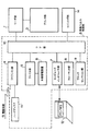
図1は、本発明の実施形態における画像形成装置の構成を示すブロック図である。図において、リーダ部1は原稿の画像を読み取り、原稿画像に応じた画像データをプリンタ部2および画像入出力制御部3へ出力する。プリンタ部2は、リーダ部1および画像入出力制御部3からの画像データに応じた画像を記録紙上に記録する。画像入出力制御部3はリーダ部1に接続されており、ファクシミリ部4、ファイル部5、ネットワーク用のコンピュータインタフェース部7、フォーマッタ部8、ブロックセレクション部9およびコア部10などを含む。
【0019】
ファクシミリ部4は、電話回線13を介して受信した圧縮画像データを伸長して、伸長された画像データをコア部10へ転送する。またコア部10から転送された画像データを圧縮して、圧縮された圧縮画像データを電話回線13を介して送信する。ファクシミリ部4にはハードディスク11が接続されており、受信した圧縮画像データを一時的に保存することができる。
【0020】
ファイル部5には外部記憶装置、すなわち光磁気ディスクドライブユニット6が接続されている。ファイル部5はコア部10から転送された画像データを圧縮し、その画像データを検索するためのキーワードとともに光磁気ディスクドライブユニット6にセツトされた光磁気ディスクに記憶させる。また、ファイル部5はコア部10を介して転送されたキーワードに基づいて光磁気ディスクに記憶されている圧縮画像データを検索し、検索された圧縮画像データを読み出して伸長し、伸長された画像データをコア部10へ転送する。
【0021】
コンピュータインタフェース部7は、パーソナルコンピュータあるいはワークステーション(PC/WS)12とコア部10の間のインタフェースであり、シリアルなどの基本インタフェースからLANまでサポートする。なお、ネットワーク機能としては、シリアル(SLIP)やLAN(Local Area Network)のまでサポートする。なお、ネットワーク機能としては、SLIPやLAN上でNetware,TCP/IP,Ether Talk等のプロトコルをサポートし、NFS等の上位レイヤのサービスもサポートする。
【0022】
フォーマッタ部8はPC/WS12から転送された画像を表すコードデータをプリンタ部2で記録することができる画像データに展開するものである。
ブロックセレクション部9は画像データを蓄積し、その蓄積した画像データを分析して、テキスト部とイメージ部に分類し、分類されたデータとそのレイアウト情報を関連付けて管理する。
【0023】
コア部10については後述するが、コア部10はリーダ部1、ファクシミリ部4、ファイル部5、ネットワーク・インタフェース部7、フォーマッタ部8、イメージメモリ部9、コインロボ部14のそれぞれの間のデータの流れを制御する。
【0024】
コインロボ部14は、ユーザにより投入されたコインの料金をコア部10に通知する。なお、コインロボ部14が白黒/カラーの料金を管理している場合には、コア部10に対して白黒/カラー印刷が可能かどうか、または白黒/カラー印刷それぞれの可能印刷枚数をコア部10に通知するようにしてもよい。コア部10はコインロボ部14からの通知を受けてから画面を立ち上げたり、印刷動作を実施する。
【0025】
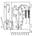
図2は、リーダ部1およびプリンタ部2の構成を示す断面図である。リーダ部1の原稿給送装置101は原稿を最終頁から順に1枚ずつプラテンガラス102上へ給送する。原稿の読取り動作終了後、プラテンガラス102上の原稿を排出する。原稿がプラテンガラス102上に搬送されると、ランプ103が点灯し、そしてスキャナユニット104の移動を開始させて、原稿を露光走査する。このときの原稿からの反射光は、ミラー105,106,107およびレンズ108によってCCDイメージセンサ(以下、CCDという)109へ導かれる。
【0026】
このように走査された原稿の画像はCCD109によって読み取られ、CCD109から出力される画像データは、所定の処理が施された後、プリンタ部2および画像入出力制御部3のコア部10へ転送される。
【0027】
プリンタ部2のレーザドライバ221はレーザ発光部201を駆動するものであり、リーダ部1から出力された画像データに応じたレーザ光を、レーザ発光部201に発光させる。このレーザ光は感光ドラム202に照射され、感光ドラム202にはレーザ光に応じた潜像が形成される。この感光ドラム202の潜像の部分には現像器203によって現像剤が付着される。そして、レーザ光の照射開始と同期したタイミングで、カセット204およびカセット205のいずれかから記録紙を給紙して転写部206へ搬送し、感光ドラム202に付着された現像剤を記録紙に転写する。現像剤の乗った記録紙は定着部207に搬送され、定着部207の熱と圧力により現像剤は記像紙に定着される。
【0028】
定着部207を通過した記録紙は排出ローラ208によって排出され、ソータ220は排出された記録紙をそれぞれのビンに収納して記録紙の仕分けを行う。なお、ソータ220は仕分けが設定されていない場合は最上ビンに記録紙を収納する。また、両面記録が設定されている場合は、排出ローラ208まで記録紙を搬送した後、排出ローラ208の回転方向を逆転させ、フラッパ209によって再給紙搬送路210へ導く。多重記録が設定されている場合には、記録紙を排出ローラ208まで搬送しないようにフラッパ209によって再給紙搬送路210へ導く。再給紙搬送路210へ導かれた記録紙は、上述したタイミングで転写部206へ給紙される。
【0029】
図3は、リーダ部1の構成例を示すブロック図である。図3において、CCD109から出力された画像データは、A/D・SH部110でアナログ/デジタル変換されるとともに、シェーディング補正が行われる。A/D・SH部110によって処理された画像データは、画像処理部111を介してプリンタ部2へ転送されるとともに、インターフェイス部113を介して画像入出力制御部3のコア部10へ転送される。
【0030】
CPU114は操作部115で設定された設定内容に応じて画像処理部111およびインターフェイス113を制御する。たとえば操作部115でトリミング処理を行って複写を行う複写モードが設定されている場合は、画像処理部111でトリミング処理を行わせてプリンタ部2へ転送させる。また、操作部115でファクシミリ送信モードが設定されている場合は、インターフェイス113から画像データと、設定されたモードに応じた制御コマンドとをコア部10へ転送させる。このようなCPU114の制御プログラムはメモリ116に記憶されており、CPU114はこのメモリ116を参照しながら制御を行う。また、メモリ116はCPU114の作業領域としても使われる。
【0031】
図4は、コア部10の構成例を示すブロック図である。図4において、リーダ部1からの画像データはインターフェイス122を介してデータ処理部121へ転送される。また、リーダ部1からの制御コマンドはインターフェイス122を介してCPU123へ転送される。データ処理部121は画像の回転処理や変倍処理などの画像処理を行う。リーダ部1からデータ処理部121へ転送された画像データは、リーダ部1から転送された制御コマンドに応じて、インターフェイス120を介してファクシミリ部4、ファイル部5、コンピュータインタフェース部7へ転送される。
【0032】
また、コンピュータインタフェ一ス部7を介して入力された画像を表すコードデータは、データ処理部121に転送された後フォーマッタ部8へ転送されて画像データに展開される。この画像データはデータ処理部121に転送された後、ファクシミリ部4やプリンタ部2へ転送される。ファクシミリ部4からの画像データは、データ処理部121へ転送された後、プリンタ部2やファイル部5、コンピュータインタフェース部7へ転送される。また、ファイル部5からの画像データは、データ処理部121へ転送された後、プリンタ部2やファクシミリ部4、コンピュータインタフェース部7へ転送される。
また、コインロボ部14からの情報は、インタフェース125を介してCPU123へ転送される。
【0033】
CPU123はメモリ124に記憶されている制御プログラムおよびリーダ部1から転送された制御コマンドに従って、このような制御を行う。また、メモリ124はCPU123の作業領域としても使われる。このようにコア部10を中心にして原稿画像の読取り、画像のプリント、画像の送受信、画像の保存、コンピュータからのデータの入出力などの機能を複合させた処理を行うことが可能である。
【0034】
つぎに図5は、本実施形態における画像形成装置の課金システムのフローを示している。
図5のステップS501において、電源投入時にコア部10のもとで通常のコピー立上げ動作を実施する。フォーマッタ部8(PDL)に対しては、初期化処理を実施するが、通常PC/WS12からPDL(Page Description Language )データ受付可能モードまで移行せず、プリント待機中としてPDLデータを受け付けない状態でとめる。
【0035】
なお、PDLデータは、図7に示すような論理構造になっている。図7において701はヘッダ部であり、記述言語(LIPS)、用紙サイズ、片面/両面等の出力モード、印刷部数等の設定に関する情報を示す。702はヘッダ部701に示された記述言語で書かれた印刷データを示す。なお、複数ページ分のデータが書かれている場合もある。
【0036】
ステップS502において、すべてのセットアップが完了した時点で、操作部124でコイン投入画面を表示する。
ステップS503において、コインロボ14にコインが投入されればステップS504へ進み、投入されなければステップS503に戻る。なお、ステップS503では、印刷に必要なコインの枚数(料金)を判断するのではなく、コインが投入されたかどうかを判断している。これは、印刷をしようとしているユーザが複合機のそばにいることを判断するために行なっている。したがって、ステップS503でコインが投入された場合には、ユーザが近くにいるものとみなしてステップS504以降の処理を行なうことになる。
【0037】
ステップS504において、コア部10は、コインロボ14からのコイン投入を受けて、プリントレディ信号をONにする。この信号を受けてフォーマッタ部8(PDL)は、印字データ受付け可能とする。
【0038】
ステップS505において、PC/WS12の操作、もしくは操作部115の操作により、PC/WS12からPDLデータをコンピュータインタフェース部7経由でフォーマッタ部8に転送し、実際に展開する。そしてヘッダ部107を解釈することにより出力モードとして、白黒/カラー、用紙サイズ、解像度および片面/両面を明らかにし、片面印刷ならばステップS506へ、両面印刷ならばステップS511へ移行する。
【0039】
片面印刷の場合はステップS506において、ステップS505で明らかにした出力モード(白黒/カラー、用紙サイズ、解像度、片面/両面)をコア部10に通知する。
ステップS507において、ステップS505で確定した出力モードに基いて、コピーの課金と同じ方法で1枚目の印刷に必要な料金の算出を実施する。コインロボ14に投入されている金額が足りていればステップS508へ、足りていなければステップS502へ戻る。
ステップS508において、フォーマッタ部8から印刷データをコア部10に渡し、実際に印刷を実行し、ステップS509において、コインロボ14に投入された料金から印刷した料金を差し引く等の実際の課金処理を行なう。
【0040】
ステップS510において、ステップS505で展開したデータで印刷していないページがあるかを判断し、すべてのページの印刷が終了していれば処理を終了する。印刷するページがある場合は、ステップS507に戻り、ステップS507、ステップS508、ステップS509で残りのページの印刷を行なう。
また、両面印刷の場合はステップS511において、フォーマッタ部8で展開したデータが両面分(1面目と2面目)あるかを判別する。両面分のデータがある場合は、ステップS512において、ステップS505で明らかにした1面目と2面目の両方合せた出力モード(白黒/カラー、用紙サイズ、解像度、両面印刷)をコア部10に通知する。
【0041】
ステップS513において、ステップS505で確定した出力モードに基き、1枚目(両面分)の印刷に必要な料金を算出を実施する。コインロボ14に投入されている金額が足りていればステップS514へ、足りていなければステップS518へ移行し、操作部124でコイン投入画面を表示する。ステップS519において、コインロボ14にコインが投入されると、ステップS513に戻る。
【0042】
ステップS514において、フォーマッタ部8から両面分の印刷データをコア部10に渡し、実際に印刷を実行し、ステップS515においてコインロボ14に投入された料金から印刷した料金を差し引く等の実際の課金処理を行なう。
スッテプS516では、ステップS505で展開したデータで印刷していないぺ一ジがあるかを判断し、すべてのぺ一ジの印刷が終了していれば処理を終了する。印刷するぺ一ジがある場合は、ステップS517において、まだ印刷していないデータが両面分あるかを判断し、両面分ある場合はステップS512に戻り、上述した両面印刷の処理を行い、両面分ない場合、すなわち片面分しかない場合は、最終ぺ一ジと判断し、ステップS507に進み、上述した片面印刷の処理を行う。
【0043】
また、ステップS511において、両面分のデータがない場合、すなわちスナッブS505で展開したデータが片面分しかない場合は、図6のステップS520において、2面目のデータを受け付けるために、フォーマッタ部8(PDL)を、PDLデータ受付け可能とする。そして、PC/WS12からPDLデータが転送されてくると、ステップS521において、フォーマッタ部8において転送されてきたデータを展開し、展開したデータのヘッダ部701を解釈することにより出力モード(白黒/カラー、用紙サイズ、解像度および片面/両面)を明らかにし、ステップS505において解析した出力モードと一致するかを判別する。
【0044】
この判別の結果、出力モードが一致すれば、ステップS512に進み、ステップS505で展開した1面目のデータとステップS521で展開した2面目のデータとを両面分のデータとして出力モードと共にコア部10に通知し、ステップS513以降の両面印刷の処理を行う。
【0045】
また、ステップS521において、出力モードが一致しない場合は、ステップS522に進む。ステップS522では、操作部115の表示部に「片面印刷しますか?」等のメッセージを表示することにより、ステップS505で展開したデータと、ステップS521で展開したデータの夫々を片面印刷してよいかをユーザに問い合わせ、操作部115の操作により片面印刷が指示されると、ステップS506に進み、上述したステップS506以降の処理を行うことにより、解析した出力モードの両面の項目を片面にして、ステップS505で展開したデータと、ステップS521で展開したデータの夫々を片面印刷する。
ステップS522において、片面印刷が指示されない場合はステップS520に戻り、両面印刷が指定されているデータの受信を再度行う。
【0046】
ここで、上述した実施形態の機能を実現するように各種のデバイスを動作させるように、上記各種デバイスと接続された装置あるいはシステム内のコンピュータに対し、上記実施形態の機能を実現するためのソフトウェアのプログラムコードを供給し、そのシステムあるいは装置のコンピュータ(CPUあるいはMPU)に格納されたプログラムに従って上記各種デバイスを動作させることによって実施したものも、本発明の範疇に含まれる。
【0047】
また、この場合、上記ソフトウェアのプログラムコード自体が上述した実施形態の機能を実現することになり、そのプログラムコード自体、およびそのプログラムコードをコンピュータに供給するための手段、例えばかかるプログラムコードを格納した記憶媒体は本発明を構成する。かかるプログラムコードを記憶する記憶媒体としては、例えばフロッピーディスク、ハードディスク、光ディスク、光磁気ディスク、CD−ROM、磁気テープ、不揮発性のメモリカード、ROM等を用いることができる。
【0048】
また、コンピュータが供給されたプログラムコードを実行することにより、上述の実施形態の機能が実現されるだけでなく、そのプログラムコードがコンピュータにおいて稼働しているOS(オペレーティングシステム)あるいは他のアプリケーションソフト等の共同して上述の実施形態の機能が実現される場合にもかかるプログラムコードは本発明の実施形態に含まれることは言うまでもない。
【0049】
さらに、供給されたプログラムコードがコンピュータの機能拡張ボードやコンピュータに接続された機能拡張ユニットに備わるメモリに格納された後、そのプログラムの指示に基づいてその機能拡張ボードや機能拡張ユニットに備わるCPU等が実際の処理の一部または全部を行い、その処理によって上述した実施形態の機能が実現される場合にも本発明に含まれる。
【0050】
【発明の効果】
以上説明したように本発明によれば、コピー課金のシステムをプリンタ機能を有する画像形成装置で有効利用することができる。特に白黒/カラー、用紙サイズ、解像度、片面/両面を指定できるプリントの際の両面印刷時のユーザの負荷を削減することができ、また両面印刷時に料金不足の片面中断といったリカバーの複雑な処理を実施する必要もなくなる。
【図面の簡単な説明】
【図1】本発明の実施形態における画像処理装置のブロック図である。
【図2】本発明の実施形態におけるリーダ部およびプリンタ部の断面図である。
【図3】本発明の実施形態におけるリーダ部のブロック図である。
【図4】本発明の実施形態におけるコア部のブロック図である。
【図5】本発明の実施形態における課金システムの動作例を示すフローチャート図である。
【図6】本発明の実施形態における課金システムの動作例を示すフローチャート図である。
【図7】本発明の実施形態におけるPDLデータの論理構造を示す図である。
【符号の説明】
1 リーダ部
2 プリンタ部
3 画像入出力制御部
4 ファクシミリ部
5 ファイル部
7 コンピュータインタフェース部
8 フォーマッタ部
9 ブロックセレクション部、
10 コア部
11 ハードディスク部
12 PC/WS部
14 コインロボ部
101 原稿給送装置
102 プラテンガラス
103 ランプ
104 スキャナユニット
105,106,107 ミラー
109 CCD
110 A/D・SH部
111 画像処理部
113 インターフェイス
114 CPU
115 操作部
116 メモリ
121 データ処理部
123 CPU
124 メモリ
201 レーザ発光部
202 感光ドラム
203 現像器
204,205 カセット
206 転写部
207 定着部
208 排出ローラ
209 フラッパ
210 再給紙搬送路
220 ソータ
221 レーザドライバ[0001]
BACKGROUND OF THE INVENTION
The present invention relates to an image forming apparatus, and more particularly to an image forming apparatus capable of duplex printing and a control method thereof.
[0002]
[Prior art]
Along with the digitalization of copiers, multi-function machines that have multiple functions, such as a facsimile function that performs facsimile transmission and reception using the scanner function and printer function of the copier, and a PDL (Page Description Language) printer, have been put into practical use. . This type of multifunction device is configured to be operable not only with a single function such as a copier function, a facsimile function or a PDL print function, but also between a plurality of functions such as facsimile transmission of a PDL developed image, for example. . Further, by connecting the multifunction peripheral via a LAN, the functions of the multifunction peripheral can be used even in a computer device or the like.
[0003]
In addition, in a copying machine, an apparatus having a function of performing a charging process on a single side / double side, a paper size of an image, a paper type, the number of paper sheets, color / monochrome, etc. has been put into practical use. In this copying machine, since the original is read one by one (one side) at the time of duplex copying, the processing is interrupted and charged each time one side is printed.
[0004]
The reason why there was no problem even if the printing on one side was interrupted in this way mainly at the time of the pressure plate is that the user who requested double-sided printing inserted coins and printed while grasping the progress.
[0005]
[Problems to be solved by the invention]
On the other hand, in the case of PDL, at the time of double-sided printing, data for both sides are requested to be printed together, so that it is not possible to divert the processing of a conventional copier that performs charging processing for each side as it is.
That is, even if data for both sides is received, if only one side is printed due to a lack of fees (coins), complicated processing is required from the user. For example, if the user sends two pages of data and only one-side printing is performed, in order to print the second page, the user must edit the data and send the data again for the second page.
[0006]
In view of such circumstances, the present invention provides an image forming apparatus capable of double-sided printing that can be appropriately and efficiently controlled, and that can reduce the load on the user when the transferred data is double-sided printed, and a control method therefor. For the purpose.
[0007]
[Means for Solving the Problems]
An image forming apparatus according to the present invention is an image forming apparatus capable of duplex printing, receiving means for receiving code data representing an image to be printed and analyzing means for analyzing a header portion of the code data received by the receiving means And, based on the analysis result of the header part by the analyzing unit, the image data obtained by developing the code data received by the receiving unit is subjected to monochrome printing or color printing, a paper size and resolution at the time of print output, Recognizing means for recognizing an output mode indicating single-sided printing or double-sided printing, and one sheet of duplex printing in the output mode recognized by the recognizing means when the output mode recognized by the recognizing means indicates double-sided printing Determining means for determining whether or not the necessary amount of money has been input by the user, and the amount of money required for the double-sided printing by the determination by the determining means Yes but if it is determined not to be turned on, and control means for controlling so as not be single-sided printing, the When the output mode of the first code data received by the receiving unit is double-sided printing, it is determined whether or not the first code data has data for one sheet on both sides. When there is data, if the amount necessary for printing one sheet on both sides of the first code data is input, printing for one sheet on both sides is executed. If the amount is not input, single-sided printing is also performed. Without waiting for the amount to be inserted, and when there is only one side of data during the double-sided printing of the first code data, the single-sided data is printed on one side, When the output mode of the first code data is double-sided printing and the received first code data does not include data for one sheet on both sides, the same output mode as the first code data is output. Second code day Data is received and both sides of the first code data and the second code data are printed on both sides if the amount of money necessary for printing one sheet on both sides of the output mode is input. It is characterized by doing.
[0013]
Further, the control method of the image forming apparatus according to the present invention includes a receiving step of receiving code data representing an image to be printed, an analyzing step of analyzing a header portion of the code data received in the receiving step, and the analyzing step Based on the analysis result of the header part, the image data obtained by developing the code data received in the receiving step is printed in black and white or color, paper size and resolution when printing out, single-sided printing or double-sided printing A recognition step for recognizing an output mode indicating whether or not, and when the output mode recognized in the recognition step indicates double-sided printing, the amount of money required for one sheet of double-sided printing in the output mode recognized in the recognition step is A judgment step for judging whether or not the money has been thrown in, and the amount required for one double-sided printing by the judgment in the judgment step. If it is determined that that is not, Yes and a control step of controlling so as not be single-sided printing, the If the output mode of the received first code data is duplex printing, it is determined whether or not the first code data has data for one sheet on both sides. If the amount necessary for printing one sheet on both sides of the first code data is input, printing for one sheet on both sides is executed, and if the amount is not input, the one-side printing is not performed and the amount is printed. And when the first code data is being printed on both sides, if only the data for one side runs out, the data for one side is printed on one side, while the first code data is printed on the other side. If the code data output mode is duplex printing and the received first code data does not contain data for one sheet, the second code in the same output mode as the first code data. Data is received, and Perform the duplex printing data amount necessary for printing both sides one sheet is a combination of the said said first code data if it is turned on the second code data of said output mode It is characterized by doing.
[0017]
In addition, the present invention program Any of the above Of image forming device To make the computer function as each means , A program executed by a computer It is.
[0018]
DETAILED DESCRIPTION OF THE INVENTION
Hereinafter, preferred embodiments of the present invention will be described with reference to the drawings.
FIG. 1 is a block diagram illustrating a configuration of an image forming apparatus according to an embodiment of the present invention. In the figure, a
[0019]
The
[0020]
An external storage device, that is, a magneto-optical disk drive unit 6 is connected to the file unit 5. The file unit 5 compresses the image data transferred from the
[0021]
The computer interface unit 7 is an interface between a personal computer or workstation (PC / WS) 12 and the
[0022]
The
The
[0023]
Although the
[0024]
The
[0025]
FIG. 2 is a cross-sectional view illustrating the configuration of the
[0026]
The image of the original scanned in this way is read by the
[0027]
The laser driver 221 of the
[0028]
The recording paper that has passed through the fixing unit 207 is discharged by the
[0029]
FIG. 3 is a block diagram illustrating a configuration example of the
[0030]
The
[0031]
FIG. 4 is a block diagram illustrating a configuration example of the
[0032]
In addition, code data representing an image input via the computer interface unit 7 is transferred to the
Information from the
[0033]
The
[0034]
Next, FIG. 5 shows a flow of a charging system of the image forming apparatus in the present embodiment.
In step S501 of FIG. 5, a normal copy startup operation is performed under the
[0035]
The PDL data has a logical structure as shown in FIG. In FIG. 7,
[0036]
In step S502, when all the setups are completed, the
In step S503, if a coin is inserted into the
[0037]
In step S504, the
[0038]
In step S505, the PDL data is transferred from the PC /
[0039]
In the case of single-sided printing, in step S506, the output mode (monochrome / color, paper size, resolution, single-sided / double-sided) clarified in step S505 is notified to the
In step S507, based on the output mode determined in step S505, the fee required for printing the first sheet is calculated by the same method as that for copying. If the amount inserted in the
In step S508, the print data is transferred from the
[0040]
In step S510, it is determined whether there is a page that has not been printed with the data developed in step S505. If printing of all pages has been completed, the process ends. If there is a page to be printed, the process returns to step S507, and the remaining pages are printed in step S507, step S508, and step S509.
In the case of double-sided printing, it is determined in step S511 whether the data developed by the
[0041]
In step S513, the fee required for printing the first sheet (both sides) is calculated based on the output mode determined in step S505. If the amount inserted in the
[0042]
In step S514, the print data for both sides is transferred from the
In step S516, it is determined whether there is a page that has not been printed with the data developed in step S505. If printing of all pages has been completed, the process ends. If there is a page to be printed, it is determined in step S517 whether there is data that has not been printed yet on both sides, and if there is data on both sides, the process returns to step S512 to perform the above-described double-sided printing process. If not, that is, if there is only one side, it is determined as the final page, and the process proceeds to step S507 to perform the above-described single-sided printing process.
[0043]
In step S511, if there is no data for both sides, that is, if the data developed in the snubber S505 is only for one side, the formatter unit 8 (PDL) is used to accept the data on the second side in step S520 in FIG. ) Can accept PDL data. When the PDL data is transferred from the PC /
[0044]
As a result of the determination, if the output modes match, the process proceeds to step S512, and the first side data developed in step S505 and the second side data developed in step S521 are output to the
[0045]
If the output mode does not match in step S521, the process proceeds to step S522. In step S522, a message such as “Do you want to print on one side?” Or the like is displayed on the display unit of the
If it is determined in step S522 that single-sided printing is not instructed, the process returns to step S520, and data for which double-sided printing is designated is received again.
[0046]
Here, software for realizing the functions of the above-described embodiments for an apparatus or a computer in the system connected to the various devices so that the various devices are operated so as to realize the functions of the above-described embodiments. The program implemented by supplying the program code and operating the various devices according to the program stored in the computer (CPU or MPU) of the system or apparatus is also included in the scope of the present invention.
[0047]
In this case, the program code of the software itself realizes the functions of the above-described embodiments, and the program code itself and means for supplying the program code to the computer, for example, the program code is stored. The storage medium constitutes the present invention. As a storage medium for storing the program code, for example, a floppy disk, a hard disk, an optical disk, a magneto-optical disk, a CD-ROM, a magnetic tape, a nonvolatile memory card, a ROM, or the like can be used.
[0048]
Further, by executing the program code supplied by the computer, not only the functions of the above-described embodiments are realized, but also the OS (operating system) or other application software in which the program code is running on the computer, etc. It goes without saying that the program code is also included in the embodiment of the present invention even when the functions of the above-described embodiment are realized jointly.
[0049]
Further, after the supplied program code is stored in the memory provided in the function expansion board of the computer or the function expansion unit connected to the computer, the CPU provided in the function expansion board or function expansion unit based on the instructions of the program, etc. However, the present invention also includes a case where the function of the above-described embodiment is realized by performing part or all of the actual processing.
[0050]
【The invention's effect】
As described above, the present invention Yo Thus, the copy charging system can be effectively used in an image forming apparatus having a printer function. In particular For printing that can specify black and white / color, paper size, resolution, single side / double side It is possible to reduce the load on the user at the time of duplex printing, and it is not necessary to carry out a complicated process of recovery such as a one-side interruption with insufficient charge at the time of duplex printing.
[Brief description of the drawings]
FIG. 1 is a block diagram of an image processing apparatus according to an embodiment of the present invention.
FIG. 2 is a cross-sectional view of a reader unit and a printer unit in the embodiment of the present invention.
FIG. 3 is a block diagram of a reader unit in the embodiment of the present invention.
FIG. 4 is a block diagram of a core unit in the embodiment of the present invention.
FIG. 5 is a flowchart showing an operation example of the accounting system in the embodiment of the present invention.
FIG. 6 is a flowchart showing an operation example of the accounting system in the embodiment of the present invention.
FIG. 7 is a diagram showing a logical structure of PDL data in the embodiment of the present invention.
[Explanation of symbols]
1 Reader section
2 Printer section
3 Image input / output controller
4 Facsimile Department
5 File part
7 Computer interface
8 Formatter section
9 Block selection section,
10 Core part
11 Hard disk part
12 PC / WS Department
14 Coin Robot
101 Document feeder
102 Platen glass
103 lamp
104 Scanner unit
105,106,107 mirror
109 CCD
110 A / D / SH Department
111 Image processing unit
113 interface
114 CPU
115 Operation unit
116 memory
121 Data processing unit
123 CPU
124 memory
201 Laser emission part
202 Photosensitive drum
203 Developer
204,205 cassette
206 Transfer section
207 Fixing part
208 discharge roller
209 Flapper
210 Refeed conveyance path
220 Sorter
221 Laser driver
Claims (5)
印刷出力する画像を表すコードデータを受信する受信手段と、
前記受信手段により受信したコードデータのヘッダ部を解析する解析手段と、
前記解析手段による前記ヘッダ部の解析結果に基づいて、前記受信手段により受信した前記コードデータを展開した画像データを白黒印刷するかカラー印刷するか、印刷出力する際の用紙サイズ及び解像度、片面印刷するか両面印刷するかを示す出力モードを認識する認識手段と、
前記認識手段により認識された出力モードが両面印刷を示す場合、前記認識手段により認識された出力モードでの両面印刷1枚に必要な金額がユーザにより投入されたかを判断する判断手段と、
前記判断手段による判断により前記両面印刷1枚に必要な金額が投入されていないと判断された場合は、片面印刷も行わないように制御する制御手段と、を有し、
前記受信手段により受信された第1のコードデータの出力モードが両面印刷の場合、当該第1のコードデータが両面1枚分のデータがあるか否かを判別し、両面1枚分のデータがある場合は当該第1のコードデータの両面1枚分の印刷に必要な金額が投入されていれば当該両面1枚分の印刷を実行し、当該金額が投入されていなければ片面印刷も行わずに当該金額が投入されるまで待機し、さらに、前記第1のコードデータの両面印刷を行っている最中に片面分のデータしかなくなると、当該片面分のデータを片面印刷し、
一方、前記第1のコードデータの出力モードが両面印刷にもかかわらず、受信した前記第1のコードデータに両面1枚分のデータが含まれていない場合、当該第1のコードデータと同じ出力モードの第2のコードデータが受信され、かつ、当該出力モードの両面1枚分の印刷に必要な金額が投入されていれば前記第1のコードデータと前記第2のコードデータとを合わせたデータの両面印刷を実行することを特徴とする画像形成装置。An image forming apparatus capable of duplex printing,
Receiving means for receiving code data representing an image to be printed out;
Analyzing means for analyzing a header portion of the code data received by the receiving means;
Based on the analysis result of the header section by the analyzing unit, the image data obtained by developing the code data received by the receiving unit is printed in black and white or color, or the paper size and resolution when printing out, single-sided printing Recognition means for recognizing an output mode indicating whether to perform double-sided printing;
When the output mode recognized by the recognizing unit indicates double-sided printing, a determining unit that determines whether an amount necessary for one double-sided printing in the output mode recognized by the recognizing unit is input by the user;
Control means for controlling so as not to perform single-sided printing when it is determined by the determination by the determination means that the necessary amount of money for one sheet of double-sided printing has not been input ,
When the output mode of the first code data received by the receiving means is double-sided printing, it is determined whether or not the first code data has data for one side of both sides, and the data for one side of the double side is obtained. In some cases, if the amount necessary for printing one sheet of both sides of the first code data is input, printing for one sheet of both sides is executed, and if the amount is not input, single-sided printing is not performed. Until the amount of money is inserted, and when there is only one side of data during the double-sided printing of the first code data, the single-sided data is printed on one side,
On the other hand, when the output mode of the first code data is duplex printing and the received first code data does not include data for one sheet on both sides, the same output as the first code data is output. If the second code data of the mode is received and the amount of money necessary for printing one sheet on both sides of the output mode is input, the first code data and the second code data are combined. An image forming apparatus that performs double-sided printing of data .
前記判断手段による判断により前記両面印刷1枚に必要な金額が投入されていないと判断された場合は、料金の投入を促す通知を行うことを特徴とする画像形成装置。The image forming apparatus according to claim 1.
An image forming apparatus characterized in that, when it is determined by the determination means that the necessary amount of money is not input for one sheet of double-sided printing, a notification that prompts the user to input a fee is provided.
前記受信手段により受信したコードデータを画像データに展開するフォーマッタ手段と、
投入金額に係らず、ユーザにより金銭が投入されたことを検出すると、前記フォーマッタ手段を前記受信手段からのコードデータを受け付けない状態から受け付ける受付状態に切替える切替手段と、を有し、
前記切替手段により前記受信手段からのコードデータを受け付ける受付状態に切替えられると、前記解析手段は前記受信手段により受信したコードデータのヘッダ部を解析することを特徴とする画像形成装置。The image forming apparatus according to claim 1.
Formatter means for developing the code data received by the receiving means into image data;
Switching means for switching the formatter means from a state not accepting code data from the receiving means to an accepting state when detecting that the user has inserted money regardless of the amount of money to be inserted,
2. The image forming apparatus according to claim 1, wherein when the switching unit is switched to a receiving state for receiving code data from the receiving unit, the analyzing unit analyzes a header portion of the code data received by the receiving unit.
印刷出力する画像を表すコードデータを受信する受信工程と、
前記受信工程において受信したコードデータのヘッダ部を解析する解析工程と、
前記解析工程における前記ヘッダ部の解析結果に基づいて、前記受信工程において受信した前記コードデータを展開した画像データを白黒印刷するかカラー印刷するか、印刷出力する際の用紙サイズ及び解像度、片面印刷するか両面印刷するかを示す出力モードを認識する認識工程と、
前記認識工程において認識された出力モードが両面印刷を示す場合、前記認識工程において認識された出力モードでの両面印刷1枚に必要な金額がユーザにより投入されたかを判断する判断工程と、
前記判断工程における判断により前記両面印刷1枚に必要な金額が投入されていないと判断された場合は、片面印刷も行わないように制御する制御工程と、を有し、
受信した第1のコードデータの出力モードが両面印刷の場合、当該第1のコードデータが両面1枚分のデータがあるか否かを判別し、両面1枚分のデータがある場合は当該第1のコードデータの両面1枚分の印刷に必要な金額が投入されていれば当該両面1枚分の印刷を実行し、当該金額が投入されていなければ片面印刷も行わずに当該金額が投入されるまで待機し、さらに、前記第1のコードデータの両面印刷を行っている最中に片面分のデータしかなくなると、当該片面分のデータを片面印刷し、
一方、前記第1のコードデータの出力モードが両面印刷にもかかわらず、受信した前記第1のコードデータに両面1枚分のデータが含まれていない場合、当該第1のコードデータと同じ出力モードの第2のコードデータが受信され、かつ、当該出力モードの両面1枚分の印刷に必要な金額が投入されていれば前記第1のコードデータと前記第2のコードデータとを合わせたデータの両面印刷を実行することを特徴とする画像形成装置の制御方法。A method for controlling an image forming apparatus capable of duplex printing,
A receiving process for receiving code data representing an image to be printed;
An analysis step of analyzing the header portion of the code data received in the reception step;
Based on the analysis result of the header portion in the analysis step, the image data obtained by developing the code data received in the reception step is printed in black and white, color printed, paper size and resolution when printing out, single-sided printing A recognition process for recognizing an output mode indicating whether to perform double-sided printing,
When the output mode recognized in the recognition step indicates double-sided printing, a determination step of determining whether the amount required for one double-sided printing in the output mode recognized in the recognition step has been input by the user;
When the amount of money required for one said double-sided printing by the determination at decision step is determined not to be turned on, possess a control step of controlling so as not be single-sided printing, a,
When the output mode of the received first code data is duplex printing, it is determined whether or not the first code data has data for one sheet on both sides. If the amount necessary for printing one sheet of both sides of one code data is input, printing for one sheet on both sides is executed. If the amount is not input, the amount is input without performing single-sided printing. In addition, when there is only one side of data during the double-sided printing of the first code data, the single-sided data is printed on one side,
On the other hand, if the output mode of the first code data is duplex printing and the received first code data does not include data for one sheet on both sides, the same output as the first code data is output. If the second code data of the mode is received and the amount of money necessary for printing one sheet on both sides of the output mode is input, the first code data and the second code data are combined. A control method for an image forming apparatus, wherein double-sided printing of data is executed .
Priority Applications (3)
| Application Number | Priority Date | Filing Date | Title |
|---|---|---|---|
| JP2001050973A JP4612775B2 (en) | 2000-02-29 | 2001-02-26 | Image forming apparatus and control method thereof |
| US09/793,097 US7190484B2 (en) | 2000-02-29 | 2001-02-27 | Cash operated image forming apparatus and its control method |
| US11/097,342 US7728993B2 (en) | 2000-02-29 | 2005-04-04 | Image forming apparatus, control method and storage medium in which a selecting device selects a print function or a copy function |
Applications Claiming Priority (3)
| Application Number | Priority Date | Filing Date | Title |
|---|---|---|---|
| JP2000052918 | 2000-02-29 | ||
| JP2000-52918 | 2000-02-29 | ||
| JP2001050973A JP4612775B2 (en) | 2000-02-29 | 2001-02-26 | Image forming apparatus and control method thereof |
Publications (3)
| Publication Number | Publication Date |
|---|---|
| JP2001318781A JP2001318781A (en) | 2001-11-16 |
| JP2001318781A5 JP2001318781A5 (en) | 2008-04-10 |
| JP4612775B2 true JP4612775B2 (en) | 2011-01-12 |
Family
ID=26586330
Family Applications (1)
| Application Number | Title | Priority Date | Filing Date |
|---|---|---|---|
| JP2001050973A Expired - Fee Related JP4612775B2 (en) | 2000-02-29 | 2001-02-26 | Image forming apparatus and control method thereof |
Country Status (1)
| Country | Link |
|---|---|
| JP (1) | JP4612775B2 (en) |
Families Citing this family (2)
| Publication number | Priority date | Publication date | Assignee | Title |
|---|---|---|---|---|
| EP2257037A3 (en) * | 2003-07-29 | 2011-06-15 | Ricoh Company, Ltd. | Image forming apparatus as client of a distributed file system, image processing method, image processing program and recording medium |
| JP7009285B2 (en) * | 2018-03-30 | 2022-01-25 | キヤノン株式会社 | Printing device, control method of printing device, and printing system |
Citations (5)
| Publication number | Priority date | Publication date | Assignee | Title |
|---|---|---|---|---|
| JPH1097395A (en) * | 1996-09-19 | 1998-04-14 | Canon Inc | Print controller, print control method for printer device, and storage medium stored with computer-readable program |
| JPH10143032A (en) * | 1996-11-07 | 1998-05-29 | Minolta Co Ltd | Image forming device |
| JPH11167323A (en) * | 1997-12-03 | 1999-06-22 | Minolta Co Ltd | Printing system using communication line |
| JPH11184655A (en) * | 1997-12-19 | 1999-07-09 | Ricoh Co Ltd | Printing system |
| JPH11272134A (en) * | 1998-03-25 | 1999-10-08 | Minolta Co Ltd | Image forming device |
-
2001
- 2001-02-26 JP JP2001050973A patent/JP4612775B2/en not_active Expired - Fee Related
Patent Citations (5)
| Publication number | Priority date | Publication date | Assignee | Title |
|---|---|---|---|---|
| JPH1097395A (en) * | 1996-09-19 | 1998-04-14 | Canon Inc | Print controller, print control method for printer device, and storage medium stored with computer-readable program |
| JPH10143032A (en) * | 1996-11-07 | 1998-05-29 | Minolta Co Ltd | Image forming device |
| JPH11167323A (en) * | 1997-12-03 | 1999-06-22 | Minolta Co Ltd | Printing system using communication line |
| JPH11184655A (en) * | 1997-12-19 | 1999-07-09 | Ricoh Co Ltd | Printing system |
| JPH11272134A (en) * | 1998-03-25 | 1999-10-08 | Minolta Co Ltd | Image forming device |
Also Published As
| Publication number | Publication date |
|---|---|
| JP2001318781A (en) | 2001-11-16 |
Similar Documents
| Publication | Publication Date | Title |
|---|---|---|
| US8509674B2 (en) | Image forming system, control method therefor, and a storage medium storing a program for executing the control method for preventing automatic recover of interrupted jobs | |
| EP0854632B1 (en) | Image forming apparatus and method of forming images | |
| JP4510652B2 (en) | Image processing apparatus, information processing method, program, and storage medium | |
| US7728993B2 (en) | Image forming apparatus, control method and storage medium in which a selecting device selects a print function or a copy function | |
| JP4748785B2 (en) | Information processing apparatus, data processing method, storage medium, and computer program | |
| JP4181661B2 (en) | Image processing apparatus, data processing method for image processing apparatus, and storage medium storing computer-readable program | |
| JP3703375B2 (en) | Image processing apparatus and image processing method | |
| JP4845700B2 (en) | Image forming apparatus and control method thereof | |
| JP4612775B2 (en) | Image forming apparatus and control method thereof | |
| JP4508445B2 (en) | Image forming apparatus, control method thereof, and program | |
| JP2004012599A (en) | Image processing system | |
| JP4574033B2 (en) | Image forming apparatus and control method thereof | |
| JP2003011443A (en) | Imaging apparatus, printing control method, program and storage medium | |
| JP3720535B2 (en) | Image forming apparatus and control method thereof | |
| JPH09247347A (en) | Processor and method for image processing | |
| JP2005078490A (en) | Image processing device | |
| JPH1142834A (en) | Image processing apparatus and method for controlling output thereof | |
| JP2002165058A (en) | Image forming device and image forming method | |
| JPH11252288A (en) | Image reader and storage medium read by computer | |
| JP2006150801A (en) | Image forming device | |
| JPH09139789A (en) | Image forming device | |
| JP2001245083A (en) | Composite machine and its control method | |
| JP2000184108A (en) | Image forming device and control method for the device | |
| JPH11338315A (en) | Device and method for forming image, and recording medium recording image forming control program | |
| JP2002374385A (en) | Imaging device and control method for the same |
Legal Events
| Date | Code | Title | Description |
|---|---|---|---|
| A521 | Written amendment |
Free format text: JAPANESE INTERMEDIATE CODE: A523 Effective date: 20080226 |
|
| A621 | Written request for application examination |
Free format text: JAPANESE INTERMEDIATE CODE: A621 Effective date: 20080226 |
|
| A977 | Report on retrieval |
Free format text: JAPANESE INTERMEDIATE CODE: A971007 Effective date: 20091225 |
|
| A131 | Notification of reasons for refusal |
Free format text: JAPANESE INTERMEDIATE CODE: A131 Effective date: 20100112 |
|
| A521 | Written amendment |
Free format text: JAPANESE INTERMEDIATE CODE: A523 Effective date: 20100310 |
|
| A02 | Decision of refusal |
Free format text: JAPANESE INTERMEDIATE CODE: A02 Effective date: 20100525 |
|
| A521 | Written amendment |
Free format text: JAPANESE INTERMEDIATE CODE: A523 Effective date: 20100820 |
|
| A911 | Transfer to examiner for re-examination before appeal (zenchi) |
Free format text: JAPANESE INTERMEDIATE CODE: A911 Effective date: 20100903 |
|
| TRDD | Decision of grant or rejection written | ||
| A01 | Written decision to grant a patent or to grant a registration (utility model) |
Free format text: JAPANESE INTERMEDIATE CODE: A01 Effective date: 20101012 |
|
| A01 | Written decision to grant a patent or to grant a registration (utility model) |
Free format text: JAPANESE INTERMEDIATE CODE: A01 |
|
| A61 | First payment of annual fees (during grant procedure) |
Free format text: JAPANESE INTERMEDIATE CODE: A61 Effective date: 20101016 |
|
| FPAY | Renewal fee payment (event date is renewal date of database) |
Free format text: PAYMENT UNTIL: 20131022 Year of fee payment: 3 |
|
| R150 | Certificate of patent or registration of utility model |
Free format text: JAPANESE INTERMEDIATE CODE: R150 |
|
| LAPS | Cancellation because of no payment of annual fees |