JP4602203B2 - Game machine - Google Patents
Game machine Download PDFInfo
- Publication number
- JP4602203B2 JP4602203B2 JP2005250347A JP2005250347A JP4602203B2 JP 4602203 B2 JP4602203 B2 JP 4602203B2 JP 2005250347 A JP2005250347 A JP 2005250347A JP 2005250347 A JP2005250347 A JP 2005250347A JP 4602203 B2 JP4602203 B2 JP 4602203B2
- Authority
- JP
- Japan
- Prior art keywords
- combination
- symbol
- stop
- winning combination
- process proceeds
- Prior art date
- Legal status (The legal status is an assumption and is not a legal conclusion. Google has not performed a legal analysis and makes no representation as to the accuracy of the status listed.)
- Active
Links
- 239000004973 liquid crystal related substance Substances 0.000 claims description 73
- 239000002131 composite material Substances 0.000 claims description 7
- 230000004044 response Effects 0.000 claims description 6
- 230000008859 change Effects 0.000 claims description 4
- 238000000034 method Methods 0.000 description 285
- 230000008569 process Effects 0.000 description 285
- 238000003860 storage Methods 0.000 description 127
- 241000167854 Bourreria succulenta Species 0.000 description 69
- 235000019693 cherries Nutrition 0.000 description 69
- PZTQVMXMKVTIRC-UHFFFAOYSA-L chembl2028348 Chemical compound [Ca+2].[O-]S(=O)(=O)C1=CC(C)=CC=C1N=NC1=C(O)C(C([O-])=O)=CC2=CC=CC=C12 PZTQVMXMKVTIRC-UHFFFAOYSA-L 0.000 description 49
- 238000012545 processing Methods 0.000 description 20
- 235000013647 Prunus pensylvanica Nutrition 0.000 description 17
- 240000007942 Prunus pensylvanica Species 0.000 description 17
- 238000003780 insertion Methods 0.000 description 16
- 230000037431 insertion Effects 0.000 description 16
- 230000000694 effects Effects 0.000 description 15
- 238000012544 monitoring process Methods 0.000 description 13
- 238000013461 design Methods 0.000 description 12
- 238000005070 sampling Methods 0.000 description 9
- 230000007704 transition Effects 0.000 description 9
- 239000010408 film Substances 0.000 description 6
- 230000002093 peripheral effect Effects 0.000 description 6
- 238000001514 detection method Methods 0.000 description 5
- 230000009471 action Effects 0.000 description 4
- 239000011521 glass Substances 0.000 description 4
- NJPPVKZQTLUDBO-UHFFFAOYSA-N novaluron Chemical compound C1=C(Cl)C(OC(F)(F)C(OC(F)(F)F)F)=CC=C1NC(=O)NC(=O)C1=C(F)C=CC=C1F NJPPVKZQTLUDBO-UHFFFAOYSA-N 0.000 description 4
- 239000000758 substrate Substances 0.000 description 4
- 238000012546 transfer Methods 0.000 description 4
- 241000282806 Rhinoceros Species 0.000 description 3
- 230000008901 benefit Effects 0.000 description 3
- 230000015572 biosynthetic process Effects 0.000 description 3
- 238000004891 communication Methods 0.000 description 3
- 238000004519 manufacturing process Methods 0.000 description 3
- 238000003825 pressing Methods 0.000 description 3
- 230000001681 protective effect Effects 0.000 description 3
- 230000000737 periodic effect Effects 0.000 description 2
- 239000010409 thin film Substances 0.000 description 2
- 230000001960 triggered effect Effects 0.000 description 2
- 239000004925 Acrylic resin Substances 0.000 description 1
- 229920000178 Acrylic resin Polymers 0.000 description 1
- VAYOSLLFUXYJDT-RDTXWAMCSA-N Lysergic acid diethylamide Chemical compound C1=CC(C=2[C@H](N(C)C[C@@H](C=2)C(=O)N(CC)CC)C2)=C3C2=CNC3=C1 VAYOSLLFUXYJDT-RDTXWAMCSA-N 0.000 description 1
- BQCADISMDOOEFD-UHFFFAOYSA-N Silver Chemical compound [Ag] BQCADISMDOOEFD-UHFFFAOYSA-N 0.000 description 1
- XAGFODPZIPBFFR-UHFFFAOYSA-N aluminium Chemical compound [Al] XAGFODPZIPBFFR-UHFFFAOYSA-N 0.000 description 1
- 229910052782 aluminium Inorganic materials 0.000 description 1
- 230000005540 biological transmission Effects 0.000 description 1
- 238000012790 confirmation Methods 0.000 description 1
- 238000010586 diagram Methods 0.000 description 1
- 238000005457 optimization Methods 0.000 description 1
- 229920006267 polyester film Polymers 0.000 description 1
- 230000033764 rhythmic process Effects 0.000 description 1
- 238000007789 sealing Methods 0.000 description 1
- 229910052709 silver Inorganic materials 0.000 description 1
- 239000004332 silver Substances 0.000 description 1
- 239000012780 transparent material Substances 0.000 description 1
- 238000007740 vapor deposition Methods 0.000 description 1
Images


Classifications
-
- G—PHYSICS
- G07—CHECKING-DEVICES
- G07F—COIN-FREED OR LIKE APPARATUS
- G07F17/00—Coin-freed apparatus for hiring articles; Coin-freed facilities or services
- G07F17/32—Coin-freed apparatus for hiring articles; Coin-freed facilities or services for games, toys, sports, or amusements
- G07F17/3202—Hardware aspects of a gaming system, e.g. components, construction, architecture thereof
- G07F17/3204—Player-machine interfaces
- G07F17/3211—Display means
-
- G—PHYSICS
- G07—CHECKING-DEVICES
- G07F—COIN-FREED OR LIKE APPARATUS
- G07F17/00—Coin-freed apparatus for hiring articles; Coin-freed facilities or services
- G07F17/32—Coin-freed apparatus for hiring articles; Coin-freed facilities or services for games, toys, sports, or amusements
- G07F17/34—Coin-freed apparatus for hiring articles; Coin-freed facilities or services for games, toys, sports, or amusements depending on the stopping of moving members in a mechanical slot machine, e.g. "fruit" machines
Description
本発明は、遊技機に関する。 The present invention relates to a gaming machine.
例えば、停止ボタンを備えたスロットマシン、いわゆるパチスロ機は、正面の表示窓内に複数の図柄を表示する機械的回転リールを複数配列して構成した変動表示装置、或いはリール上の図柄を画面に表示する電気的変動表示装置を有する。遊技者のスタート操作に応じて、制御手段が変動表示装置を駆動して各リールを回転させることにより、図柄を変動表示させ、一定時間後自動的に或いは遊技者の停止操作により、各リールの回転を順次停止させる。このとき、表示窓内に現れた各リールの図柄が特定の組合せ(入賞図柄)になった場合にコイン、メダル等の遊技媒体を払出すことで遊技者に利益を付与するものである。 For example, a slot machine equipped with a stop button, a so-called pachislot machine, has a variable display device configured by arranging a plurality of mechanical rotating reels that display a plurality of symbols in the front display window, or a symbol on the reel on the screen. It has an electrical fluctuation display device for displaying. In response to the player's start operation, the control means drives the variable display device to rotate the reels to display the symbols in a variable manner. After a certain period of time, either automatically or by the player's stop operation, Stop rotation sequentially. At this time, when the symbols of the reels appearing in the display window are in a specific combination (winning symbol), the player is given a profit by paying out game media such as coins and medals.
現在主流の機種は、複数種類の入賞態様を有するものである。特に、所定の役の入賞が成立したときは、1回のコインの払出しに終わらず、所定期間、通常の状態よりも条件の良い遊技状態となる。このような役として、遊技者に相対的に大きい利益を与えるゲームが所定回数行える役(「ビッグボーナス」と称し、以下「BB」と略記する)と、遊技者に相対的に小さい利益を与える遊技を所定ゲーム数行える役(「レギュラーボーナス」と称し、以下「RB」と略記する)がある。 Currently, the mainstream model has a plurality of types of winning modes. In particular, when a winning combination of a predetermined combination is established, the game state is better in condition than the normal state for a predetermined period of time, instead of completing one coin payout. As such a combination, a combination that can play a game that gives a relatively large profit to the player a predetermined number of times (referred to as “Big Bonus”, hereinafter abbreviated as “BB”) and a relatively small profit to the player There is a role that can play a predetermined number of games (referred to as “regular bonus”, hereinafter abbreviated as “RB”).
このような遊技機は、その仕様によっては善良の風俗を害するおそれのあるものとされているが、遊技機を製造する際には、著しく射幸心を煽ることがないようにする等、社会に与える影響に留意しなければならない。この判断基準として、「風俗営業等の規則及び業務の適正化等に関する法律」における「遊技機の認定及び型式等に関する規則」があるが、ここに示される数値等の基準は、遊技機が善良の風俗を害するか否かを判断する社会的に認められた唯一の基準であり、遊技機を製造する上で非常に重要なものとなっている。 Depending on the specifications of such a gaming machine, it may be harmful to good manners, but when manufacturing a gaming machine, it should We must pay attention to the impact. As this judgment standard, there is the “Rules for Approval and Model of Pachislot Machines” in the “Rules on Customs Business etc. and the Act on Optimization of Businesses”. It is the only socially recognized standard for judging whether or not the customs are harmed, and is extremely important in the manufacture of gaming machines.
例えば、役物連続作動増加装置(以下、「BB」という)が作動することとなる図柄の組合せ(図柄組合せ)の数は、BB中に役物連続作動装置(以下、「RB」という)が3回作動したときに終了する遊技機にあっては、全ての図柄の組合せの数の千五百分の一を、超えるものでないことが規定(上記規則の別表第五(1)トの(ヘ)において規定)されている。このような遊技機は、通常有効ラインを5ラインと規定し、このことからBBの図柄組合せが有効ライン上に表示される期待値は、三百分の一となる(引込制御は考慮していない)。 For example, the number of symbol combinations (symbol combinations) at which the accessory continuous action increasing device (hereinafter referred to as “BB”) is activated is the number of symbol combinations (symbol combinations) within the BB. It is stipulated that gaming machines that end when operated three times do not exceed one-hundred thousandth of the number of all combinations of symbols ((5) (1) ( F). In such a gaming machine, the normal effective line is defined as 5 lines, and therefore, the expected value at which the symbol combination of BB is displayed on the effective line is one-third (the pull-in control is taken into consideration). Absent).
上述した5ラインの遊技機では、停止制御に係る停止データ量が多くなる反面、停止出目(図柄の停止態様)が単調になりにくい。つまり、多様な停止出目を表示することができる利点がある。また、1遊技に賭ける賭け枚数を1枚とした場合、有効ラインが1ライン、2枚とした場合3ライン、3枚とした場合5ラインとされ、BBの内部当選確率が賭け枚数に応じて設定されている。賭け枚数を1枚とした場合の内部当選確率が3枚に比べて低く設定されており、賭け枚数が少ない程該内部当選確率は低くなる。上述した図柄組合せが有効ライン上に表示される表示確率は内部当選確率の±20%の範囲と規定され、表示上の確率である表示確率と抽選上の確率である内部当選確率とをかけ離れた値にはできない。 In the 5-line gaming machine described above, the amount of stop data related to stop control increases, but the stop appearance (symbol stop mode) is less likely to be monotonous. That is, there is an advantage that various stop events can be displayed. Also, if the number of bets placed on one game is 1, the number of active lines is 1 line, 2 lines are 3 lines, 3 lines are 5 lines, and the internal winning probability of BB depends on the number of bets Is set. When the bet number is one, the internal winning probability is set lower than three, and the smaller the bet number, the lower the internal winning probability. The display probability that the above-mentioned symbol combination is displayed on the active line is defined as a range of ± 20% of the internal winning probability, and the display probability that is the display probability is far from the internal winning probability that is the lottery probability. It cannot be a value.
ここで、上記5ライン機に代わる有効ラインを1ラインとした1ライン機が考えられる。このような1ライン機では、有効ラインが5ライン機に比べて少ないことから、当選役に対応する図柄組合せが有効ライン上に表示される割合が減少し、有効ライン上の停止出目も単調となりやすく、面白みに欠けるおそれがあるという問題がある。 Here, a one-line machine with one effective line instead of the five-line machine can be considered. In such a one-line machine, since the number of active lines is smaller than that in the 5-line machine, the proportion of symbol combinations corresponding to the winning combination is displayed on the active line, and the stop appearance on the active line is also monotonous. There is a problem that it is easy to become, and there is a possibility of lack of interest.
また、現在主流の機種においては、有効化された成立ライン(以下「有効ライン」という)に沿って所定の図柄の組合せが並び、コイン、メダル等が払出される入賞が成立するには、内部的な抽選処理(以下「内部抽選」という)により役に当選(以下「内部当選」という)し、且つその内部当選した役(以下「内部当選役」という)の入賞成立を示す図柄の組合せを有効ラインに停止できるタイミングで遊技者が停止操作を行うことが要求される。つまり、いくら内部当選したとしても、遊技者の停止操作のタイミングが悪いと入賞を成立させることができない。すなわち、停止操作のタイミングに熟練した技術が要求される(「目押し」といわれる技術介入性の比重が高い)遊技機が現在の主流である。 In addition, in the current mainstream models, a combination of predetermined symbols is arranged along an activated formation line (hereinafter referred to as an “effective line”), and in order to achieve a winning in which coins, medals, etc. are paid out, A combination of symbols indicating winning of the winning combination (hereinafter referred to as “internal winning combination”) and winning a winning combination (hereinafter referred to as “internal winning combination”) through a typical lottery process (hereinafter referred to as “internal lottery”) The player is required to perform a stop operation at a timing at which the player can stop at the active line. In other words, no matter how much the internal winning is made, if the timing of the stop operation of the player is bad, a winning cannot be established. That is, gaming machines that require skill in the timing of the stop operation (the high importance of technical intervention called “to push”) are currently mainstream.
このような遊技機では、前記制御装置(20)は、役に当選したかハズレかの抽選を行うための役抽選手段(110)と、役抽選手段(110)の抽選結果に基づいて回転リールの停止制御を行うための停止制御手段(180)と、すべての回転リール(40)の回転が停止した際における図柄の停止位置によって入賞か否かの判定を行うための入賞判定手段(200)とを備え、前記役抽選手段(110)は、1回の遊技で複数個の役を当選させることができるように形成されていることを特徴とするものが提案されている(例えば、特許文献1参照)。この遊技機によれば、1回の遊技で複数個の役を当選させることができる。このため、役のバリエーションが豊富になり、これにより、遊技が単調にならないようにすることができるので、遊技者の興趣を高めることができる。
しかしながら、上記の遊技機では、単に、1回の遊技で複数個の役を当選させるだけであり、面白みに欠ける。 However, the above gaming machine simply wins a plurality of roles in one game and lacks interest.
本発明の目的は、所定の役に当選していることに対する期待感により、遊技の興趣を向上させることができる遊技機を提供することである。 An object of the present invention is to provide a gaming machine that can improve the interest of a game due to a sense of expectation that a predetermined role has been won.
本発明は、以上のような問題点に鑑みてなされたものであり、遊技機において、停止制御手段は、単位遊技において、複合役が当選役として決定され、停止テーブルが選択されていないときには、引込み優先順位テーブルに基づき停止操作位置から最大滑りコマ数の範囲内で予め定められた引込み優先順位の高い役に対応する図柄組合せを構成する引込み図柄を検索し、上記範囲内に引込み図柄が存在する場合には当該引込み図柄を有効ライン上に停止させる制御を行い、検索の結果範囲内に引込み図柄が存在しない場合には優先順位の低い役に対応する停止テーブルを選択し、選択した停止テーブルに基づいてこの停止操作が行われた停止信号出力手段に対応する図柄表示手段の停止制御を行い、停止テーブルを選択した後は残りの変動中の図柄表示手段の停止制御を選択した停止テーブルに基づいて行うことを特徴とする。 The present invention has been made in view of the problems as described above, and in the gaming machine, the stop control means, in the unit game, when the combined combination is determined as the winning combination, and the stop table is not selected, Based on the pull-in priority table, search for pull-in symbols that constitute a symbol combination corresponding to a combination with a high pull-in priority determined in advance within the range of the maximum number of sliding frames from the stop operation position, and there is a pull-in symbol within the above range performs control to stop the retraction symbol enable line on in the case of, when the pull-symbol in the result range of the search does not exist select stop table stop that corresponds to the low priority role, selected Based on the stop table, stop control of the symbol display means corresponding to the stop signal output means for which the stop operation has been performed, and after the stop table is selected, the remaining fluctuations And performing based on the stop table selected stop control of symbol display unit.
より具体的には、本発明では、以下のようなものを提供する。 More specifically, the present invention provides the following.
(1) 複数の図柄を表示する複数の図柄表示手段(例えば、後述のリール3L,3C,3R、後述の図柄表示領域21L,21C,21Rなど)と、遊技者による操作(例えば、後述のスタート操作など)に応じて、単位遊技(例えば、後述の一のゲームなど)の開始を指令する信号を出力する開始信号出力手段(例えば、後述のスタートスイッチ6S、後述の主制御回路71など)と、前記開始信号出力手段の操作に基づいて乱数を抽出し(例えば、後述の図41のステップS205の処理など)、その乱数に基づいて複数種類の役の中から、1の役が決定される単独役、複数の役が同時に決定される複合役、から当選役を決定する当選役決定手段(例えば、後述の確率抽選処理を行う手段、後述の主制御回路71など)と、前記開始信号出力手段により信号が出力されることを条件に、前記図柄表示手段により表示される図柄の変動(例えば、変動表示など)を行う図柄変動手段(例えば、後述のステッピングモータ49L,49C,49R、後述の主制御回路71など)と、遊技者による操作(例えば、後述の停止ボタン7L,7C,7Rの操作など)に応じて、前記図柄変動手段により行われる図柄の変動の停止を前記複数の図柄表示手段の各々に指令する信号(例えば、後述の停止指令信号など)を出力する前記複数の図柄表示手段の各々に対応して設けられた複数の停止信号出力手段(例えば、後述の停止スイッチ7LS,7CS,7RSなど)と、前記当選役のそれぞれに対応する図柄組合せを構成する図柄を停止可能とする停止テーブルと、前記当選役が複合役の場合、前記複数の役の引込み優先順位を規定する引込み優先順位テーブルと、前記停止信号出力手段により出力された信号と当選役決定手段により決定された当選役とに基づいて、前記停止信号が出力された位置から予め定められた最大滑りコマ数(例えば、後述の4コマなど)の範囲内で前記図柄変動手段により行われる図柄の変動の停止制御を行う停止制御手段(例えば、後述の滑りコマ数決定処理を行う手段、後述の図50のステップS314を行う手段、後述の主制御回路71など)と、予め定められた図柄組合せ(例えば、後述のベルの小役に対応する図柄組合せなど)が前記図柄表示手段により表示されると、遊技者に利益(例えば、メダルの払出し、メダルの自動投入、後述の遊技状態の移行など)を付与する利益付与手段(例えば、後述の図42のステップS216を行う手段、後述の主制御回路71など)と、を備え、前記停止制御手段は、前記単位遊技において、前記複合役が前記当選役として決定され、停止テーブルが選択されていないときには、前記引込み優先順位テーブルに基づき停止操作位置から最大滑りコマ数の範囲内で予め定められた引込み優先順位の高い役に対応する図柄組合せを構成する引込み図柄を検索し(例えば、後述の図51のステップS323〜327の処理など)、前記範囲内に前記引込み図柄が存在する場合には当該引込み図柄を有効ライン上に停止させる制御を行い、前記検索の結果前記範囲内に前記引込み図柄が存在しない場合には前記優先順位の低い役に対応する停止テーブルを選択し(例えば、後述の図51のステップS328の処理など)、選択した停止テーブルに基づいてこの停止操作が行われた停止信号出力手段に対応する図柄表示手段の停止制御を行い、前記停止テーブルを選択した後は残りの変動中の図柄表示手段の停止制御を選択した停止テーブルに基づいて(例えば、後述の図49のステップS213の処理など)行うことを特徴とする遊技機。
(1) A plurality of symbol display means for displaying a plurality of symbols (for example,
(2) (1)記載の遊技機において、前記複数種類の役には、前記単独役又は前記複合役のいずれかから当選役として決定される第1の役(例えば、後述の図33のMB1,MB2など)と、前記第1の役とともに決定される前記複合役のみで当選役として決定される第2の役(例えば、後述の図33のハイサイなど)と、前記単独役、又は前記第1の役とともに決定される前記複合役のいずれかから当選役として決定される第3の役と、が含まれ、(例えば、後述の図33のBARベルなど)前記当選役決定手段が前記第1の役を当選役と決定することを条件に、前記第1の役に対応する図柄組合せが前記複数の図柄表示手段により表示されるまでの間、前記第1の役を当選役として持ち越す持越手段(例えば、後述の図47のステップS275、281の処理など)を備え、前記利益付与手段は、前記第1の役に対応する図柄組合せが前記複数の図柄表示手段により表示されることを条件に遊技者にとって相対的に有利な有利状態の作動を行う有利状態作動手段(例えば、後述の図42のステップS220の処理を行う手段など)と、前記第2の役に対応する図柄組合せが前記複数の図柄表示手段により表示されることを条件に遊技価値を遊技者に付与(例えば、後述の図42のステップS216など)し、前記第3の役に対応する図柄組合せが前記複数の図柄表示手段により表示されることを条件に前記遊技価値又はこれとは別の遊技価値を遊技者に付与する遊技価値付与手段と、含むことを特徴とする遊技機。 (2) In the gaming machine described in (1), the plurality of types of combinations include a first combination determined as a winning combination from either the single combination or the combined combination (for example, MB1 in FIG. 33 described later). , MB2, etc.), the second combination determined as the winning combination only by the combination combination determined together with the first combination (for example, the high rhino in FIG. 33 described later), the single combination, or the first combination A third combination determined as a winning combination from any one of the combined combinations determined together with the first combination (for example, a BAR bell in FIG. 33 to be described later) Carrying over the first combination as a winning combination until the combination of symbols corresponding to the first combination is displayed by the plurality of symbol display means on condition that one combination is determined to be a winning combination Means (for example, step S in FIG. 47 described later) 275, 281, etc.), and the profit providing means is relatively advantageous for the player on condition that the symbol combination corresponding to the first combination is displayed by the plurality of symbol display means. Advantageous state actuating means for actuating the state (for example, means for performing step S220 in FIG. 42 described later) and a symbol combination corresponding to the second combination are displayed by the plurality of symbol display means. The game value is given to the player on the condition (for example, step S216 in FIG. 42 described later), and the symbol combination corresponding to the third combination is displayed by the plurality of symbol display means. A gaming machine comprising game value providing means for providing a player with a game value or another game value .
(2)記載の遊技機によれば、複数種類の役には、単独役又は複合役のいずれかから当選役として決定される第1の役と、第1の役との複合役のみで当選役として決定される第2の役と、単独役、又は第1の役との複合役のいずれかから当選役として決定される第3の役と、が含まれる。持越手段は、当選役決定手段が第1の役を当選役と決定することを条件に、第1の役に対応する図柄組合せが複数の図柄表示手段により表示されるまでの間、第1の役を当選役として持ち越す。利益付与手段は、
第1の役に対応する図柄組合せが複数の図柄表示手段により表示されることを条件に遊技者にとって相対的に有利な有利状態の作動を行う有利状態作動手段と、第2の役に対応する図柄組合せが複数の図柄表示手段により表示されることを条件に遊技価値を遊技者に付与し、第3の役に対応する図柄組合せが複数の図柄表示手段により表示されることを条件に遊技価値又はこれとは別の遊技価値を遊技者に付与する遊技価値付与手段と、を含むしたがって、第2の役が当選役である場合には、必ず第1の役が当選役として決定され、第3の役が当選役である場合には、第1の役が当選役として決定される場合と第1の役が当選役として決定されない場合とがある。すなわち、第2の役に対応する図柄組合せが表示された場合には、必ず第1の役に当選しているが、第3の役に対応する図柄組合せが表示された場合には、第1の役に当選していない場合がある。また、第2の役に対応する図柄組合せが図柄表示手段により表示されると、当選役決定手段により第2の役とともに当選役として決定された第1の役に対応する図柄組合せが図柄表示手段により表示されないので、持越手段により第1の役が持ち越される。他方、第3の役に対応する図柄組合せが図柄表示手段により表示されると、当選役決定手段により第3の役とともに当選役として決定された第1の役に対応する図柄組合せが図柄表示手段により表示されないので、持越手段により第1の役が持ち越される場合があるが、当選役決定手段により第3の役のみが決定された場合には第1の役が持ち越されない。表示された図柄組合せが第2の役又は第3の役のいずれに対応するものであるかにより、第1の役が持ち越されていることに対する遊技者の期待感を異ならせることができるので、遊技の興趣を向上させることができる。遊技者にとってみれば、第1の役が持ち越され、第1の役に対応する図柄組合せが図柄表示手段により表示されて有利な状態が作動することに対する期待の度合いが異なるので、遊技を十分に楽しむことができる。
(2) According to the gaming machine described in the above, a plurality of types of winning combinations are won only by the first combination determined as the winning combination from either the single combination or the combined combination and the combined combination of the first combination. A second combination determined as a combination and a third combination determined as a winning combination from either a single combination or a combined combination with the first combination are included. The carryover means is configured to display the first combination until the symbol combination corresponding to the first combination is displayed by the plurality of symbol display means on the condition that the winning combination determining unit determines the first combination as the winning combination. Carry the role as a winning role. Profit grant means
Advantageous state operating means for performing an advantageous state operation relatively advantageous to the player on condition that a symbol combination corresponding to the first combination is displayed by a plurality of symbol display means, and corresponding to the second combination Game value is given to the player on condition that the symbol combination is displayed by a plurality of symbol display means, and game value is provided on condition that the symbol combination corresponding to the third role is displayed by the plurality of symbol display means Or a game value giving means for giving a player a different game value to the player. Therefore, when the second role is a winning role, the first role is always determined as the winning role, When the third combination is a winning combination, there are a case where the first combination is determined as the winning combination and a case where the first combination is not determined as the winning combination. That is, when the symbol combination corresponding to the second combination is displayed, the first combination is always won, but when the symbol combination corresponding to the third combination is displayed, the first combination is displayed. You may not be elected for the role. When the symbol combination corresponding to the second combination is displayed by the symbol display means, the symbol combination corresponding to the first combination determined as the winning combination together with the second combination by the winning combination determining means is displayed as the symbol combination means. The first combination is carried over by the carryover means. On the other hand, when the symbol combination corresponding to the third combination is displayed by the symbol display means, the symbol combination corresponding to the first combination determined as the winning combination together with the third combination by the winning combination determining means is the symbol display means. , The first combination may be carried over by the carryover means. However, when only the third combination is determined by the winning combination determination means, the first combination is not carried over. Depending on whether the displayed symbol combination corresponds to the second role or the third role, the player's expectation that the first role has been carried over can be varied. The interest of the game can be improved. From the player's point of view, the first combination is carried over, and the degree of expectation that the symbol combination corresponding to the first combination is displayed by the symbol display means and the advantageous state is activated is different. I can enjoy it.
(3) (1)又は(2)記載の遊技機において、前記複数の図柄表示手段前面に設けられた液晶表示装置(例えば、後述の液晶表示装置131など)と、前記液晶表示装置を制御する液晶表示制御手段(例えば、後述の副制御回路72など)と、前記液晶表示装置に設けられた3列の前記複数の図柄表示手段の前記複数の図柄を各々上段、中段、下段で視認可能な図柄表示領域(例えば、後述の図柄表示領域21L,21C,21Rなど)と、を備え、前記複数の図柄表示手段のそれぞれを直線で結んだ、前記当選役の成否を判定する前記中段を結ぶ1の有効ライン(例えば、後述のセンターライン8cなど)と、をさらに備え、前記液晶表示制御手段は、前記図柄表示領域を除く前記1の有効ライン上に沿って識別情報表示(例えば、後述の識別情報表示領域77など)を行うことを特徴とする遊技機。
(3) In the gaming machine according to (1) or (2), a liquid crystal display device (for example, a liquid
(3)記載の遊技機によれば、複数の図柄表示手段のそれぞれを直線で結んだ、当選役の成否を判定する中段を結ぶ1の有効ラインを備え、液晶表示制御手段は、図柄表示領域を除く1の有効ライン上に沿って識別情報表示を行う。したがって、識別情報表示を中段を結ぶ1の有効ラインに沿って設けることにより、遊技者は、役の成否に関わるラインが中段を結ぶ1の有効ラインのみであることを明確に把握することができる。 According to the gaming machine described in (3) , the liquid crystal display control means is provided with a symbol display area including one effective line that connects each of the plurality of symbol display means with a straight line and connects the middle stage for determining success or failure of the winning combination. Identification information is displayed along one active line excluding. Therefore, by providing the identification information display along one effective line connecting the middle stage, the player can clearly grasp that the line related to the success or failure of the combination is only one effective line connecting the middle stage. .
(4) (3)記載の遊技機において、前記液晶表示制御手段は、前記識別情報表示の表示態様を各図柄表示手段の停止表示後に変化させ(例えば、後述の図25(1)から(2)の変化など)ることを特徴とする遊技機。 (4) (3) gaming machine described, the liquid crystal display control means, a display mode of the identification information display from changing after the display stop of each figure pattern display means (e.g., Fig later 25 (1) ( A game machine characterized by 2) changes.
(4)記載の遊技機によれば、液晶表示制御手段は、識別情報表示の表示態様を各図柄表示手段の停止表示後に変化させる。したがって、識別情報表示の表示態様の変化で遊技に関連する情報を報知したり示唆したりすることも可能となり、遊技者は、その変化を確実に把握して、遊技を楽しむことができる。また、その報知により、中段を結ぶ1の有効ラインに並ぶ図柄組合せに注目させることもできる。 According to the gaming machine described in (4), the liquid crystal display control means changes the display mode of the identification information display after the stop display of each symbol display means. Therefore, it is possible to notify or suggest information related to the game by changing the display mode of the identification information display, and the player can grasp the change and enjoy the game. In addition, by the notification, attention can be paid to symbol combinations arranged in one effective line connecting the middle stages .
以下、実施例の遊技機について説明する。 Hereinafter, the gaming machine of the embodiment will be described.
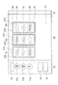
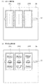
図1は、本発明の一実施例の遊技機1の外観を示す斜視図である。遊技機1は、いわゆるパチスロ機である。この遊技機1は、コイン、メダル、遊技球又はトークンなどの他、遊技者に付与された、もしくは付与される遊技価値の情報を記憶したカード等の遊技媒体を用いて遊技する遊技機であるが、以下ではメダルを用いるものとして説明する。
FIG. 1 is a perspective view showing an appearance of a
前面ドア2の正面には、略垂直面としてのパネル表示部2a、液晶表示部2b及び固定表示部2cが形成されている(後述)。また、前面ドア2の背後には、複数種類の図柄が各々の外周面に描かれた3個のリール3L,3C,3Rが、回転自在に横一列に設けられている。各リール3L,3C,3Rは、一定の速度で回転する(例えば、80回転/分)。
On the front surface of the
パネル表示部2a、液晶表示部2b及び固定表示部2cの下方には略水平面の台座部4が形成されている。台座部4の右側には、メダルを投入するためのメダル投入口10が設けられている。投入されたメダルは、クレジットされるか、ゲームに賭けられる。また、台座部4の左側には、押下操作により、クレジットされているメダルを賭けるための1−BETスイッチ11、2−BETスイッチ12、及び最大BETスイッチ13が設けられている。
A substantially
1−BETスイッチ11は、1回の押し操作により、クレジットされているメダルのうちの1枚がゲームに賭けられ、2−BETスイッチ12は、1回の押し操作により、クレジットされているメダルのうちの2枚がゲームに賭けられ、最大BETスイッチ13は、1回のゲームに賭けることが可能な最大枚数のメダルが賭けられる。
The 1-
これらのBETスイッチ11〜13を操作することで、所定の表示ラインが有効化される(後述)。BETスイッチ11〜13の操作及びメダル投入口10にメダルを投入する操作(遊技を行うためにメダルを投入する操作)を、以下「BET操作」という。また、BETスイッチ11〜13の上方には、操作部17が設けられている。操作部17は、液晶表示装置131に遊技履歴などの情報を表示するために操作される。
By operating these BET switches 11 to 13, a predetermined display line is activated (described later). The operation of the BET switches 11 to 13 and the operation of inserting a medal into the medal insertion slot 10 (the operation of inserting a medal for playing a game) are hereinafter referred to as “BET operation”. In addition, an
台座部4の前面部の左寄りには、遊技者がゲームで獲得したメダルのクレジット/払出しを押しボタン操作で切り換えるC/Pスイッチ14が設けられている。このC/Pスイッチ14の切り換えにより、正面下部のメダル払出口15からメダルが払出され、払出されたメダルはメダル受け部5に溜められる。メダル受け部5の上方の左右には、遊技の演出に関する効果音などを出音するスピーカ9L,9Rが設けられている。
A C /
C/Pスイッチ14の右側には、遊技者の操作により上記リールを回転させ、図柄表示領域21L,21C,21R内での図柄の変動表示を開始するためのスタートレバー6が所定の角度範囲で回動自在に取り付けられている。
On the right side of the C /
台座部4の前面部中央で、スタートレバー6の右側には、3個のリール3L,3C,3Rの回転をそれぞれ停止させるための3個の停止ボタン7L,7C,7Rが設けられている。なお、実施例では、一のゲーム(単位遊技)は、基本的にスタートレバー6が操作されることにより開始し、全てのリール3L,3C,3Rが停止したときに終了する。
Three
ここで、本実施例では、全てのリールが回転しているときに行われるリールの停止操作(停止ボタンの操作)を第1停止操作、第1停止操作の次に行われる停止操作を第2停止操作、第2停止操作の次に行われる停止操作を第3停止操作という。また、各停止ボタン7L,7C,7Rの裏側には、後述の図5に示す停止スイッチ7LS,7CS,7RSが配置されている。これらの停止スイッチは、対応する停止ボタンの操作(停止操作)を検知する。
In this embodiment, the reel stop operation (stop button operation) performed when all the reels are rotating is the first stop operation, and the stop operation performed after the first stop operation is the second. The stop operation performed after the stop operation and the second stop operation is referred to as a third stop operation. Further, stop switches 7LS, 7CS, and 7RS shown in FIG. 5 to be described later are arranged on the back side of the
図2を参照して、パネル表示部2a、液晶表示部2b及び固定表示部2cについて説明する。
The
パネル表示部2aは、ボーナス遊技情報表示部16、BETランプ17a〜17c、払出表示部18、及びクレジット表示部19により構成される。ボーナス遊技情報表示部16は、7セグメントLEDから成り、ボーナス中の遊技情報を表示する。1−BETランプ17a、2−BETランプ17b及び最大BETランプ17cは、一のゲームを行うために賭けられたメダルの数(以下「BET数」という)に応じて点灯する。
The
1−BETランプ17aは、BET数が1枚のときに点灯する。2−BETランプ17bは、BET数が2枚のときに点灯する。最大BETランプ17cは、BET数が3枚のときに点灯する。払出表示部18及びクレジット表示部19は、夫々7セグメントLEDから成り、入賞が成立した時(役が成立したとき)のメダルの払出枚数及びクレジットされているメダルの枚数を表示する。
The 1-
液晶表示部2bは、図柄表示領域21L,21C,21R、窓枠表示領域22L,22C,22R及び演出表示領域23により構成される。この液晶表示部2bの表示内容は、リール3L,3C,3Rの回転及び停止態様、及び後述の液晶表示装置131(後述の図3参照)の動作により変化するようになっている。
The liquid
図柄表示領域21L,21C,21Rは、各リール3L,3C,3Rに対応して設けられ、リール3L,3C,3R上に配置された図柄の表示や、種々の演出表示を行う。
The
図柄表示領域21L,21C,21Rには、表示ラインとして、水平方向にトップライン8b、センターライン8c及びボトムライン8d、並びに、斜め方向にクロスアップライン8a及びクロスダウンライン8eが設けられる。これらの表示ラインは、遊技者が、前述のBETスイッチ11〜13を押下操作すること、又はメダル投入口10にメダルを投入することにより、それぞれ1本、3本、5本が有効化される(以下、有効化された表示ラインを「有効ライン」と記載する)。どの表示ラインが有効化されたかは、前述のBETランプ17a,17b,17cの点灯で表示される。ここで、表示ライン8a〜8eは、役の成否に関わる。
In the
図柄表示領域21L,21C,21Rは、少なくとも、対応するリール3L,3C,3Rが回転中のとき、及び、対応する停止ボタン7L,7C,7Rが押下操作可能なとき、遊技者がリール3L,3C,3R上の図柄を視認できるように、透過状態となる。
The
窓枠表示領域22L,22C,22Rは、各図柄表示領域21L,21C,21Rを囲むように設けられ、リール3L,3C,3Rの前面に配置された図柄表示領域21L,21C,21Rの窓枠を表したものである。
The window
演出表示領域23は、液晶表示部2bの領域のうち、図柄表示領域21L,21C,21R及び窓枠表示領域22L,22C,22R以外の領域である。この演出表示領域23は、ボーナスが成立可能であることを確定的に報知する画像(例えば、告知ランプ)の表示、ゲームの興趣を増大するための演出、遊技者がゲームを有利に進めるために必要な情報等の表示を行う。
The
固定表示部2cは、予め定めた図、絵などが描かれる領域である。この固定表示部2cに描かれた図、絵などと、演出表示領域23に表示された画像を連接させることにより一つの静止画像又は動画像を表示できるようにしても良い。
The fixed
図3は、液晶表示装置131の概略構成を示す斜視図である。はじめに、リール3L,3C,3Rの内部構造について説明する。リール3L,3C,3Rの内部には、リール3L,3C,3Rの回転が停止した場合に各図柄表示領域21L,21C,21Rに現われる縦3列の図柄(合計9個の図柄)の裏側にLED収納用回路基板が設置されている。LED収納用回路基板は、夫々3つ(即ち合計で9つ)のLED収納部を有し、ここに複数のLEDランプが設けられている。
FIG. 3 is a perspective view showing a schematic configuration of the liquid
このLEDランプは、リール3L,3C,3Rの外周面に沿って装着されたリールシートの後面側を白色の光で照明する。より詳細には、前述の図柄表示領域21L,21C,21Rに対応する領域を照明する。このリールシートは、透光性を有して構成され、LEDランプにより出射された光は前面側へ透過するようになっている。
This LED lamp illuminates the rear surface side of the reel sheet mounted along the outer peripheral surface of the
また、左リール3Lは、同形の2本の環状フレームを所定の間隔(例えばリール幅)だけ離して複数本の連結部材で連結することで形成された円筒形のフレーム構造と、そのフレーム構造の中心部に設けられたステッピングモータ49Lの駆動力を環状フレームへ伝達する伝達部材とにより構成される。また、左リール3Lの外周面に沿ってリールシートが装着されている。
Further, the
リール3Lの内側に配置されたLED収納用回路基板は、夫々複数のLEDランプを収納する3つのLED収納部を備えている。LED収納用回路基板は、遊技者が図柄表示領域21Lを通して視認できる図柄(合計3個の図柄)の各々の裏側にLED収納部が位置するように設置されている。なお、中央リール3C,右リール3Rについては図示しないが、図示した左リール3Lと同様の構造を有し、各々の内部にLED収納用回路基板が設けられている。
The LED storage circuit board disposed inside the
次に、透過型の液晶表示装置131について説明する。液晶表示装置131は、保護ガラス132、表示板133、液晶パネル134、導光板135、反射フィルム136、白色光源(例えば全ての波長の光を人の目に特定の色彩が目立たない割合で含む)である蛍光ランプ137a,137b,138a,138b、ランプホルダ139a〜139h、液晶パネル駆動用のICを搭載したテーブルキャリアパッケージからなり液晶パネル134の端子部に接続したフレキシブル基板(図示せず)等により構成される。
Next, the transmissive liquid
この液晶表示装置131は、リール3L,3C,3Rの表示領域より正面から見て手前側(即ち表示面よりも手前側)に設けられている。また、このリール3L,3C,3Rと液晶表示装置131とは、別体で(例えば所定の間隔をあけて)設けられている。
The liquid
保護ガラス132及び表示板133は、透光性部材で構成されている。保護ガラス132は、液晶パネル134を保護すること等を目的として設けられている。表示板133において、前述のパネル表示部2a及び固定表示部2c(図2参照)に対応する領域には、図、絵などが描かれる。
The
ここで、図3では、パネル表示部2aに対応する表示板133の領域の裏側に配置される前述の各種表示部(ボーナス遊技情報表示部16、払出表示部18、クレジット表示部19など)及びBETランプ17a〜17cを動作させる電気回路の図示を省略している。
Here, in FIG. 3, the above-mentioned various display units (bonus game
液晶パネル134は、薄膜トランジスタ層が形成されたガラス板などの透明な基板と、これに対向する透明な基板との間隙部に液晶が封入されて形成されている。この液晶パネル134の表示モードは、ノーマリーホワイトに設定されている。ノーマリーホワイトとは、液晶を駆動していない状態(即ち液晶パネル134に電圧を印加していない状態)で白表示となる構成である。即ち、表示面側に光が行く、よって透過した光が外部から視認されることとなる。
The
よって、ノーマリーホワイトに構成された液晶パネル134を採用することにより、液晶を駆動できない事態が生じた場合であっても、図柄表示領域21L,21C,21Rを透してリール3L,3C,3R上に配列された図柄を視認することができ、ゲームを継続することができる。つまり、液晶を駆動できない事態が発生した場合にも、リール3L,3C,3Rの回転及びその停止を中心としたゲームを行うことができる。
Therefore, by adopting the normally white
導光板135は、蛍光ランプ137a,137bからの光を液晶パネル134へ導入する(液晶パネル134を照明する)ために液晶パネル134の裏側に設けられ、例えば2cm程度の厚さを有するアクリル系樹脂などの透光性部材(即ち導光機能を有する部材)で構成されている。
The
反射フィルム136は、例えば白色のポリエステルフィルムやアルミ薄膜に銀蒸着膜を形成したものが用いられ、導光板135に導入された光を正面側に向けて反射させる。これにより液晶パネル134を照明する。この反射フィルム136は、反射領域136A及び非反射領域(即ち透過領域)136BL,136BC,136BRにより構成されている。非反射領域136BL,136BC,136BRは、透明な材料で形成され入射した光を反射することなく透過させる光透過部として形成されている。
The
また、非反射領域136BL,136BC,136BRは、リール3L,3C,3Rの回転が停止した場合に表示させる図柄の各々の前方の位置に設けられている。尚、非反射領域136BL,136BC,136BRの大きさ及び位置は、前述の図柄表示領域21L,21C,21R(図2参照)と一致するように形成されている。また、反射フィルム136では、非反射領域136BL,136BC,136BR以外の領域を反射領域136Aとし、反射領域136Aにより導光板135に導入された光を正面側に向けて反射させる。
Further, the non-reflective areas 136BL, 136BC, and 136BR are provided at positions in front of the symbols to be displayed when the rotation of the
蛍光ランプ137a,137bは、導光板135の上端部及び下端部に沿って配置され、両端はランプホルダ139a,139b,139g,139hにより支持されている。この蛍光ランプ137a,137bは、導光板135に導入する光を発生する。
The
蛍光ランプ138a,138bは、反射フィルム136の裏側の上方位置及び下方位置に配置されている。この蛍光ランプ138a,138bから発せられた光は、リール3L,3C,3Rの表面で反射され、非反射領域136BL,136BC,136BRへ入射する。そして、入射した光は、非反射領域136BL,136BC,136BRを通過して液晶パネル134を照明する。
The
さらに、LEDランプ及び蛍光ランプ137a,137b,138a,138bの機能について説明する。
Further, the functions of the LED lamps and
はじめに、図柄表示領域21L,21C,21Rにある液晶を駆動しない場合(即ち、液晶パネル134の、図柄表示領域21L,21C,21Rに対応する個所に電圧を印加しない場合)の各ランプの機能について説明する。
First, the function of each lamp when the liquid crystal in the
蛍光ランプ138a,138bから出射された光の一部は、リールシートにより反射される。また、LED収納用回路基板に設けられた前述のLEDランプから出射された光の一部は、リールシートを透過する。これらの光は、非反射領域136BL,136BC,136BR、液晶表示装置131を構成する前述の導光板135及び液晶パネル134を透過するので、遊技者は、リール上に配置された図柄を視認することができる。
Part of the light emitted from the
また、蛍光ランプ137a,137bから出射され、導光板135に向けて導入された光は、液晶パネル134を透過して遊技者の目に入る。つまり、蛍光ランプ137a,137bによって、前述の窓枠表示領域22L,22C,22R及び演出表示領域23に対応する液晶パネル134の領域が照明される。
Further, the light emitted from the
次に、図柄表示領域21L,21C,21Rにある液晶を駆動する場合(即ち、液晶パネル134の、図柄表示領域21L,21C,21Rに対応する個所に電圧を印加する場合)の各ランプの機能について説明する。
Next, the function of each lamp when driving the liquid crystal in the
蛍光ランプ138a,138bから出射された光の一部は、リールシートにより反射される。また、LEDランプから出射された光の一部は、リールシートを透過する。液晶パネル134の領域のうち、液晶が駆動された領域では、これらの光の一部が反射或いは吸収されたり透過したりするので、遊技者は、図柄表示領域21L,21C,21Rに表示された演出画像等を視認することができる。
Part of the light emitted from the
図4は、各リール3L,3C,3Rに表わされた複数種類の図柄が21個配列された図柄列を示している。各図柄には“00”〜“20”のコードナンバーが付され、データテーブルとして後で説明するROM32(図5)に格納(記憶)されている。各リール3L,3C,3R上には、“赤7(図柄91)”、“青7(図柄92)”、“ベル(図柄93)”、“ブランク(図柄94)”、“白7(図柄95)”、“Replay(図柄96)”、及び“チェリー(図柄97)”の図柄で構成される図柄列が表わされている。各リール3L,3C,3Rは、図柄列が図4の矢印方向に移動するように回転駆動される。
FIG. 4 shows a symbol row in which 21 types of symbols represented on the
“ブランク”は、基本的に、役の成立に直接関係のない図柄である。すなわち、“ブランク”がいずれかの有効ラインに沿って並んで表示された場合でも、メダルの払出し、メダルの自動投入、後述の遊技状態の移行などの利益が遊技者に付与されることはない。 “Blank” is basically a symbol that is not directly related to the formation of a role. That is, even when “blanks” are displayed along any one of the active lines, the player is not provided with benefits such as paying out medals, automatic insertion of medals, and the transition of the gaming state described later. .
“チェリー”は、所定の変動表示部内(例えば、左の図柄表示領域21L)に停止して表示されることにより所定の役(上下チェリーの小役、中チェリーの小役)の成立が確定する図柄である。上下チェリーの小役、及び中チェリーの小役を総称して、以下「チェリーの小役」という。
“Cherry” is stopped and displayed in a predetermined fluctuation display section (for example, the left
ここで、実施例の役には、RB、白7小役、リプレイ、ベルの小役、上下チェリーの小役、及び中チェリーの小役が設けられている。また、RBは、第1種特別役物である。役(役データ)は、基本的に、遊技者に付与される利益と図柄組合せとが対応付けられた制御情報であり、リール3L,3C,3Rの停止制御、遊技状態の切り換え(移行)、遊技価値の付与などに用いられる制御情報である。
Here, RB, white 7 small part, replay, bell small part, top and bottom cherry small part, and medium cherry small part are provided in the role of the embodiment. Further, RB is a first type special combination. The combination (combination data) is basically control information in which a profit given to a player is associated with a symbol combination, stop control of the
図5は、遊技機1における遊技処理動作を制御する主制御回路71と、主制御回路71に電気的に接続する周辺装置(アクチュエータ)と、主制御回路71から送信される制御指令に基づいて液晶表示装置131、スピーカ9L,9R、LED類101及びランプ類102を制御する副制御回路72とを含む回路構成を示す。
FIG. 5 is based on a
主制御回路71は、回路基板上に配置されたマイクロコンピュータ30を主たる構成要素とし、これに乱数サンプリングのための回路を加えて構成されている。マイクロコンピュータ30は、予め設定されたプログラム(後述の図12〜図18)に従って制御動作を行うCPU31と、記憶手段であるROM32及びRAM33を含む。
The
CPU31には、基準クロックパルスを発生するクロックパルス発生回路34及び分周器35と、サンプリングされる乱数を発生する乱数発生器36及びサンプリング回路37とが接続されている。尚、乱数サンプリングのための手段として、マイクロコンピュータ30内で、即ちCPU31の動作プログラム上で、乱数サンプリングを実行するように構成してもよい。その場合、乱数発生器36及びサンプリング回路37は省略可能であり、或いは、乱数サンプリング動作のバックアップ用として残しておくことも可能である。
Connected to the
マイクロコンピュータ30のROM32には、スタートレバー6を操作(スタート操作)する毎に行われる乱数サンプリングの判定に用いられる確率抽選テーブル、停止ボタンの操作に応じてリールの停止態様を決定するための停止テーブル群などが格納されている。また、副制御回路72へ送信するための各種制御指令(コマンド)等が格納されている。副制御回路72が主制御回路71へコマンド、情報等を入力することはなく、主制御回路71から副制御回路72への一方向で通信が行われる。RAM33には、種々の情報が格納される。RAM33には、種々の情報が格納され、後述の図8に示す格納領域が設けられている。RAM33には、例えば、内部当選役、後述の持越役、現在の遊技状態などの情報等が格納される。
The
図5の回路において、マイクロコンピュータ30からの制御信号により動作が制御される主要なアクチュエータとしては、BETランプ(1−BETランプ17a、2−BETランプ17b、最大BETランプ17c)と、ボーナス遊技情報表示部16、払出表示部18、クレジット表示部19などの表示部と、メダルを収納し、ホッパー駆動回路41の命令により所定枚数のメダルを払出すホッパー(払出しのための駆動部を含む)40と、リール3L,3C,3Rを回転駆動するステッピングモータ49L,49C,49Rとがある。
In the circuit of FIG. 5, the main actuators whose operation is controlled by a control signal from the
更に、ステッピングモータ49L,49C,49Rを駆動制御するモータ駆動回路39、ホッパー40を駆動制御するホッパー駆動回路41、BETランプ17a,17b,17cを駆動制御するランプ駆動回路45、及びボーナス遊技情報表示部16、払出表示部18、クレジット表示部19などの表示部を駆動制御する表示部駆動回路48がCPU31の出力部に接続されている。これらの駆動回路は、それぞれCPU31から出力される駆動指令などの制御信号を受けて、各アクチュエータの動作を制御する。
Further, a
また、マイクロコンピュータ30が制御指令を発生するために必要な入力信号を発生する主な入力信号発生手段としては、スタートスイッチ6S、停止スイッチ7LS,7CS,7RS、1−BETスイッチ11、2−BETスイッチ12、最大BETスイッチ13、C/Pスイッチ14、メダルセンサ10S、リール位置検出回路50、払出完了信号回路51がある。
The main input signal generating means for generating an input signal necessary for the
スタートスイッチ6Sは、スタートレバー6の操作を検出する。メダルセンサ10Sは、メダル投入口10に投入されたメダルを検出する。停止スイッチ7LS,7CS,7RSは、対応する停止ボタン7L,7C,7Rの操作に応じて停止信号を発生する。リール位置検出回路50は、リール回転センサからのパルス信号を受けて各リール3L,3C,3Rの位置を検出するための信号をCPU31へ供給する。払出完了信号回路51は、メダル検出部40Sの計数値(ホッパー40から払出されたメダルの枚数)が指定された枚数データに達した時、メダル払出完了を検知するための信号を発生する。
The
図5の回路において、乱数発生器36は、一定の数値範囲に属する乱数を発生し、サンプリング回路37は、スタートレバー6が操作された後の適宜のタイミングで1個の乱数をサンプリングする。こうしてサンプリングされた乱数を使用することにより、例えばROM32内に格納されている確率抽選テーブルなどに基づいて内部当選役などが決定される。
In the circuit of FIG. 5, the
リール3L,3C,3Rの回転が開始された後、ステッピングモータ49L,49C,49Rの各々に供給される駆動パルスの数が計数され、その計数値はRAM33の所定エリアに書き込まれる。リール3L,3C,3Rからは一回転毎にリセットパルスが得られ、これらのパルスはリール位置検出回路50を介してCPU31に入力される。こうして得られたリセットパルスにより、RAM33で計数されている駆動パルスの計数値が“0”にクリアされる。これにより、RAM33内には、各リール3L,3C,3Rについて一回転の範囲内における回転位置に対応した計数値が格納される。
After the rotation of the
上記のようなリール3L,3C,3Rの回転位置とリール外周面上に描かれた図柄とを対応づけるために、図柄テーブル(図示せず)が、ROM32内に格納されている。この図柄テーブルでは、前述したリセットパルスが発生する回転位置を基準として、各リール3L,3C,3Rの一定の回転ピッチ毎に順次付与されるコードナンバーと、それぞれのコードナンバー毎に対応して設けられた図柄を示す図柄コードとが対応づけられている。
A symbol table (not shown) is stored in the
更に、ROM32内には、図柄組合せテーブル(図示せず)が格納されている。この図柄組合せテーブルでは、役の成立(入賞など)となる図柄の組合せと、入賞のメダル配当枚数と、その入賞(成立)を表わす入賞判定コード(成立判定コード)とが対応づけられている。上記の図柄組合せテーブルは、左のリール3L,中央のリール3C,右のリール3Rの停止制御時、及び全リール3L,3C,3Rの停止後の入賞確認(表示役の確認)を行う場合に参照される。表示役(表示役データ)は、基本的に、有効ラインに沿って並ぶ図柄組合せに対応する役(成立役)である。遊技者には、表示役に対応する利益が付与される。
Furthermore, a symbol combination table (not shown) is stored in the
上記乱数サンプリングに基づく抽選処理(確率抽選処理など)により内部当選役を決定した場合には、CPU31は、遊技者が停止ボタン7L,7C,7Rを操作したタイミングで停止スイッチ7LS,7CS,7RSから送られる操作信号、及び決定された停止テーブルに基づいて、リール3L,3C,3Rを停止制御する信号をモータ駆動回路39に送る。内部当選役(内部当選役データ)は、基本的に、停止制御の態様を識別したり、表示役となりうる役(表示役として許容されうる役)を識別したりするための情報である。内部当選役は、その内部当選役に対応する停止制御の態様などを介して、対応する図柄組合せと遊技者に付与される利益とが間接的に対応付けられているといえる。
When the internal winning combination is determined by the lottery process (probability lottery process or the like) based on the random number sampling, the
当選した役の入賞を示す停止態様(即ち入賞態様)となれば、CPU31は、払出指令信号をホッパー駆動回路41に供給してホッパー40から所定個数のメダルの払出を行う。その際、メダル検出部40Sは、ホッパー40から払出されるメダルの枚数を計数し、その計数値が指定された数に達した時に、メダル払出完了信号がCPU31に入力される。これにより、CPU31は、ホッパー駆動回路41を介してホッパー40の駆動を停止し、メダル払出処理を終了する。
If it becomes a stop mode (that is, a winning mode) indicating winning of the winning combination, the
図6は、各遊技状態の発生条件、移行条件、及び移行条件が充足された場合の移行先の遊技状態を示す。各遊技状態では、基本的に、内部当選する役の種類或いはその当選確率が異なる。 FIG. 6 shows the game condition of each game state, the transfer condition, and the game state of the transfer destination when the transfer condition is satisfied. In each gaming state, the type of winning combination or its winning probability is basically different.
実施例の遊技状態には、一般遊技状態、RB遊技状態、及び持越状態がある。また、この持越状態中において持ち越された役(RB)を、以下「持越役」という。 The gaming state of the embodiment includes a general gaming state, an RB gaming state, and a carryover state. In addition, the role (RB) carried over in this carryover state is hereinafter referred to as “carryover role”.
一般遊技状態は、基本的に、いわゆる「出玉率」(遊技に賭けられた単位遊技価値に対して遊技者に付与される遊技価値)の期待値が“1”よりも小さい遊技状態である。また、後述の持越役がない遊技状態であり、他の遊技状態と比べて遊技者にとって最も不利な遊技状態である。 The general gaming state is basically a gaming state in which an expected value of a so-called “play rate” (a gaming value given to a player with respect to a unit gaming value bet on a game) is smaller than “1”. . Further, it is a gaming state without a carryover role described later, and is the most disadvantageous gaming state for the player as compared with other gaming states.
RB遊技状態は、基本的に、「第1種特別役物」が作動しているゲームにより構成される遊技状態である。 The RB gaming state is basically a gaming state constituted by a game in which the “first type special object” is operating.
持越状態は、基本的に、RBに対応する図柄組合せが有効ラインに沿って並ぶこと(RBの成立)が一又は複数のゲームにわたり許容された遊技状態である。 The carryover state is basically a gaming state in which it is allowed for one or a plurality of games that the symbol combinations corresponding to the RB are arranged along the active line (RB establishment).
図6に示すように、RB遊技状態の発生条件は、RBの成立である。所定回数(例えば、12回)のゲームが終了すること、所定回数(例えば、8回)の成立が実現することという条件のうちのいずれかが成立することにより移行条件が成立し、遊技状態が一般遊技状態へ移行する。 As shown in FIG. 6, the condition for generating the RB gaming state is establishment of RB. The transition condition is established when one of the conditions that the predetermined number of times (for example, 12 times) the game is completed or the predetermined number of times (for example, 8 times) is realized, and the gaming state is established. Transition to the general gaming state.
持越状態の発生条件は、RBに内部当選することである。RBが成立することにより移行条件が成立し、遊技状態がRB遊技状態へ移行する。 The condition for the carryover state is to win the RB internally. When RB is established, the transition condition is established, and the gaming state is shifted to the RB gaming state.
図7を参照して、役と図柄組合せと払出枚数について説明する。 With reference to FIG. 7, a combination of a combination, a symbol, and a payout number will be described.
RBは、“赤7−赤7−赤7”又は“青7−青7−青7”が有効ラインに沿って並ぶことにより成立する(表示役がRBとなる)。
RB is established by arranging “red 7-red 7-
白7小役は、“白7−ベル−ベル”が有効ラインに沿って並ぶことにより成立し(表示役が白7小役となり)、メダルが15枚払出される。チェリーの小役は、“チェリー-any-any”が有効ラインに沿って並ぶことにより成立する。上下チェリーの小役が成立した場合は、メダルが4枚払出され、中チェリーの小役が成立した場合は、メダルが2枚払出される。ベルの小役が成立することとなる図柄の組合せ、及び払出枚数は図示の通りである。 The white 7 small combination is established by arranging “white 7-bell-bell” along the active line (the display combination becomes the white 7 small combination), and 15 medals are paid out. The small part of cherry is formed by "cherry-any-any" lined up along the active line. When the small cherry top combination is established, four medals are paid out, and when the middle cherry small combination is established, two medals are paid out. The combination of symbols and the number of payouts that will result in the formation of the small part of the bell are as shown.
リプレイは、“Replay−Replay−Replay”が有効ラインに沿って並ぶことにより成立する。リプレイが成立すると、投入したメダルの枚数と同数のメダルが自動投入されるので、遊技者はメダルを消費することなく次のゲームを行うことができる。すなわち、リプレイは、成立することにより遊技価値の投入をすることによらずに遊技を行うことができる役である。 Replay is established by arranging “Replay-Replay-Replay” along the active line. When the replay is established, the same number of medals as the number of inserted medals are automatically inserted, so that the player can play the next game without consuming the medals. In other words, the replay is a role that allows a game to be performed without establishing a game value when it is established.
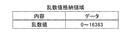
図8を参照して、内部当選役、及び持越役の格納領域(記憶領域)について説明する。 With reference to FIG. 8, the storage area (storage area) of the internal winning combination and carryover combination will be described.
図8の(1)は、内部当選役格納領域を示す。この内部当選役格納領域では、内部当選役の情報(データ)は、1バイトからなる内部当選役格納領域に格納(記憶)されている。内部当選役格納領域において、ビット0(第1ビット)は、チェリーの小役に対応する格納領域である。ビット1(第2ビット)は、ベルの小役に対応する格納領域である。 (1) of FIG. 8 shows an internal winning combination storing area. In this internal winning combination storage area, information (data) of the internal winning combination is stored (stored) in the internal winning combination storage area consisting of 1 byte. In the internal winning combination storage area, bit 0 (first bit) is a storage area corresponding to the cherry small combination. Bit 1 (second bit) is a storage area corresponding to the small part of the bell.
ビット2(第3ビット)は、リプレイに対応する格納領域である。ビット3(第4ビット)は、白7小役に対応する格納領域である。ビット4(第5ビット)は、RBに対応する格納領域である。ビット5(第6ビット)、ビット6(第7ビット)、及びビット7(第8ビット)は、未使用の格納領域である。内部当選役格納領域において、1であるビットに対応するもの(役)が内部当選役となる。例えば、内部当選役格納領域に“00000010”が格納されているとき(ビット1(第2ビット)が1のとき)は、内部当選役はベルの小役である。 Bit 2 (third bit) is a storage area corresponding to replay. Bit 3 (fourth bit) is a storage area corresponding to the white 7 small combination. Bit 4 (the fifth bit) is a storage area corresponding to RB. Bit 5 (sixth bit), bit 6 (seventh bit), and bit 7 (eighth bit) are unused storage areas. In the internal winning combination storage area, the one corresponding to the bit which is 1 (combination) is the internal winning combination. For example, when “00000010” is stored in the internal winning combination storage area (when bit 1 (second bit) is 1), the internal winning combination is a small combination of bells.
図8の(2)は、持越役格納領域を示す。この持越役格納領域では、持越役の情報は、1バイトからなる持越役格納領域に格納されている。持越役格納領域において、ビット4(第5ビット)は、RBに対応する格納領域(記憶領域)である。ビット0(第1ビット)〜ビット3(第4ビット)、ビット5(第6ビット)〜ビット7(第8ビット)は、未使用の格納領域である。持越役がある場合(持越状態)には、持越役格納領域のRBに対応するビット4(第5ビット)に1が格納される(持越役格納領域に“00010000”が格納される)。 (2) of FIG. 8 shows a carryover combination storage area. In this carryover combination storage area, carryover combination information is stored in a carryover combination storage area consisting of 1 byte. In the carryover combination storage area, bit 4 (fifth bit) is a storage area (storage area) corresponding to RB. Bit 0 (first bit) to bit 3 (fourth bit) and bit 5 (sixth bit) to bit 7 (eighth bit) are unused storage areas. When there is a carryover combination (carry-over state), 1 is stored in bit 4 (fifth bit) corresponding to the RB in the carryover combination storage area (“00010000” is stored in the carryover combination storage area).
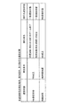
図9を参照して、確率抽選テーブル(BET数:3)について説明する。 The probability lottery table (BET number: 3) will be described with reference to FIG.
図9の(1)は、一般遊技状態用確率抽選テーブルを示す。一般遊技状態では、RB、RB+白7小役、RB+チェリーの小役、チェリーの小役、リプレイ、及びベルの小役に当選する場合がある。RB+白7小役は、乱数範囲(数値範囲)が“100”〜“199”に対応するものであり、一の抽選によりRB及び白7小役の両方が当選役となる。RB+チェリーの小役は、乱数範囲が“200”〜“299”に対応するものであり、一の抽選によりRB及びチェリーの小役の両方が当選役となる。 (1) of FIG. 9 shows a probability lottery table for a general gaming state. In the general gaming state, there are cases where RB, RB + white 7 small combination, RB + cherry small combination, cherry small combination, replay, and bell small combination are won. The RB + white 7 small combination corresponds to the random number range (numerical value range) “100” to “199”, and both the RB and the white 7 small combination become the winning combination by one lottery. The RB + cherry small combination corresponds to a random number range of “200” to “299”, and both the RB and cherry small combination are won by one lottery.
ここで、RBは、乱数範囲が“0”〜“299”(第1数値範囲の情報)に対応するものである。RBに当選となる乱数範囲の下限値(第1の下限値)は“0”であり、上限値(第1の上限値)は“299”である。すなわち、乱数範囲は“0”〜“299”である。 Here, RB corresponds to a random number range of “0” to “299” (information of the first numerical value range). The lower limit value (first lower limit value) of the random number range won for RB is “0”, and the upper limit value (first upper limit value) is “299”. That is, the random number range is “0” to “299”.
白7小役は、乱数範囲が“100”〜“199”(第2数値範囲の情報)に対応するものである。白7小役に当選となる乱数範囲の下限値(第2の下限値)は“100”であり、上限値(第2の上限値)は“199”である。 The white 7 small combination corresponds to a random number range of “100” to “199” (information of the second numerical range). The lower limit (second lower limit) of the random number range won for the white 7 small combination is “100”, and the upper limit (second upper limit) is “199”.
チェリーの小役は、乱数範囲が“200”〜“349”(第3数値範囲の情報)に対応するものである。チェリーの小役に当選となる乱数範囲の下限値(第3の下限値)は“200”であり、上限値(第3の上限値)は“349”である。 The small part of cherry corresponds to a random number range of “200” to “349” (information in the third numerical range). The lower limit value (third lower limit value) of the random number range won for the small part of cherry is “200”, and the upper limit value (third upper limit value) is “349”.
したがって、白7小役に対応する乱数範囲は、RBに対応する乱数範囲に含まれている。すなわち、白7小役に当選となる場合には、必ずRBに当選している。また、チェリーの小役に対応する乱数範囲は、RBに対応する乱数範囲の一部の範囲“200”〜“299”を含んでいる。すなわち、チェリーの小役に当選となる場合には、RBが当選している場合としていない場合とがある。 Therefore, the random number range corresponding to the white 7 small combination is included in the random number range corresponding to RB. In other words, when winning the white 7 small combination, the RB is always won. In addition, the random number range corresponding to the cherry small part includes a part of the random number range “200” to “299” corresponding to the RB. That is, when winning a cherry small role, there may be cases where the RB has won.
白7小役に当選となる乱数範囲の下限値及び上限値が、RBに当選となる乱数範囲に含まれる。すなわち、白7小役に当選となる場合には、必ずRBに当選している。他方、チェリーの小役に当選となる乱数範囲の下限値は、RBに当選となる乱数範囲に含まれるが、上限値は含まれない。すなわち、チェリーの小役に当選となる場合には、RBが当選している場合としていない場合とがある。 The lower limit and upper limit of the random number range won for the white 7 small combination are included in the random number range won for the RB. In other words, when winning the white 7 small combination, the RB is always won. On the other hand, the lower limit value of the random number range won for the small part of cherry is included in the random number range won for RB, but the upper limit value is not included. That is, when winning a cherry small role, there may be cases where the RB has won.
また、RB+白7小役に当選した場合には、RB及び白7小役に対応する図柄組合せが有効ラインに沿って並ぶことが許容されるが、RBが優先して引き込まれる。RB+チェリーの小役に当選した場合には、RB及びチェリーの小役に対応する図柄組合せが有効ラインに沿って並ぶことが許容されるが、RBが優先して引き込まれる。RB+白7小役に内部当選して白7小役が成立したりしてRBが成立しない場合には、RBが持ち越される。RB+チェリーの小役に内部当選してチェリーが成立したりしてRBが成立しない場合には、RBが持ち越される。 When RB + white 7 small combination is won, it is allowed that symbol combinations corresponding to RB and white 7 small combination are arranged along the effective line, but RB is preferentially drawn. When the RB + cherry small combination is won, the symbol combinations corresponding to the RB and cherry small combination are allowed to line up along the active line, but the RB is preferentially drawn. If the RB + white 7 small combination is won internally and the white 7 small combination is established, or the RB is not established, the RB is carried over. If an RB + cherry small role is won internally and a cherry is established, or an RB is not established, the RB is carried over.
一般遊技状態では、RB+チェリーの小役に当選した場合だけでなく、内部当選役がチェリーの小役の場合にも、チェリーの小役が成立する。また、持越状態においてもチェリーの小役が成立する。したがって、チェリーの小役が成立した場合には、RBが持ち越される場合と、持ち越されない場合とがある。他方、白7小役は、一般遊技状態では、RB+白7小役に当選した場合に成立することがある。また、持越状態においても白7小役が成立するが、その場合には、持ち越されていたRBは、次のゲームに持ち越される。したがって、白7小役が成立した場合には、必ずRBが持ち越される。 In the general game state, not only when the RB + cherry small combination is won, but also when the internal winning combination is the cherry small combination, the cherry small combination is established. Even in the carryover state, a cherry small part is established. Therefore, when the cherry small combination is established, there are cases where the RB is carried over and where it is not carried over. On the other hand, the white 7 small combination may be established in the general gaming state when RB + white 7 small combination is won. Also, in the carryover state, the white 7 small combination is established, but in that case, the RB carried over is carried over to the next game. Therefore, when a white 7 small combination is established, RB is always carried over.
遊技者にとってみれば、白7小役が成立した場合のRBに対する期待感は、チェリーの小役の場合と比べて相対的に大きい。したがって、成立した役の種類によってRB成立に対する遊技者の期待感を変化させ、遊技の興趣を向上させることができる。 For the player, the expectation for RB when the white 7 small combination is established is relatively large compared to the case of the cherry small combination. Therefore, the player's sense of expectation for the establishment of the RB can be changed depending on the type of the established combination, and the interest of the game can be improved.
なお、RB+白7小役に当選した場合には、内部当選役格納領域のRBに対応するビット4(第5ビット)及び白7小役に対応するビット3(第4ビット)の夫々に1が格納される(内部当選役格納領域に“00011000”が格納される)。RB+チェリーの小役に当選した場合には、内部当選役格納領域のRBに対応するビット4(第5ビット)及びチェリーの小役に対応するビット0(第1ビット)の夫々に1が格納される(内部当選役格納領域に“00010001”が格納される)。 When RB + white 7 small combination is won, 1 is set for each of bit 4 (fifth bit) corresponding to RB in the internal winning combination storing area and bit 3 (fourth bit) corresponding to white 7 small combination. Is stored ("00011000" is stored in the internal winning combination storage area). When RB + Cherry small combination is won, 1 is stored in bit 4 (fifth bit) corresponding to RB in the internal winning combination storage area and bit 0 (first bit) corresponding to cherry small combination. ("00010001" is stored in the internal winning combination storage area).
図9の(2)は、RB遊技状態用確率抽選テーブルを示す。このRB遊技状態では、ベルの小役、チェリーの小役に内部当選する場合がある。 (2) in FIG. 9 shows an RB gaming state probability lottery table. In this RB gaming state, there may be a case where an internal winning combination is made for a bell small part or a cherry small part.
図9の(3)は、持越状態用確率抽選テーブルを示す。持越状態では、白7小役、リプレイ、ベルの小役、チェリーの小役に内部当選する場合がある。 (3) of FIG. 9 shows the carry-over state probability lottery table. In the carry-over state, there may be cases where the internal winning combination is a white 7 small role, a replay, a bell small role, or a cherry small role.
図10を参照して、停止テーブルについて説明する。 The stop table will be described with reference to FIG.
停止テーブルは、基本的に、所定の図柄組合せ(対応する役の図柄組合せ)を所定の表示ライン(有効ライン)に沿って並べることが可能に構成されている。ただし、ハズレに対応する停止テーブルは、役に対応する図柄組合せが所定の表示ラインに沿って並べることができないように構成されている。 The stop table is basically configured so that predetermined symbol combinations (corresponding symbol combinations) can be arranged along predetermined display lines (effective lines). However, the stop table corresponding to the loss is configured such that the symbol combinations corresponding to the combination cannot be arranged along a predetermined display line.
停止テーブルには、各リール3L,3C,3Rの停止操作位置と停止制御位置とが示されている。停止操作位置は、各リール3L,3C,3Rに対応して設けられた停止ボタン7L,7C,7Rが操作された場合に、センターライン8cに位置していた図柄(具体的には、図柄の中心がセンターライン8cの上方に位置し、その中心がセンターライン8cの位置に最も近い図柄)のコードナンバーを表わす。停止制御位置は、停止操作が行われたリールが停止したとき、センターライン8cの位置に停止表示される図柄のコードナンバーを表わす。
The stop table shows stop operation positions and stop control positions of the
実施例では、いわゆる滑りコマ数を最大“4コマ”としている(最大滑りコマ数を4としている)。例えば、右のリール3Rの回転中において、コードナンバー“16”の“青7”がセンターライン8cの位置に到達したとき、停止ボタン7Rが操作された場合、コードナンバー“20”の“赤7”をセンターライン8cの位置に停止表示するように右のリール3Rを停止制御することができる。
In the embodiment, the maximum number of sliding frames is “4 frames” (the maximum number of sliding frames is 4). For example, when the “blue 7” of the code number “16” reaches the position of the
ここで、「引込み」は、基本的に、有効ラインが結ぶ図柄停止位置に、最大滑りコマ数4の条件下で引込み対象役に対応する図柄組合せを構成する図柄を表示するように、停止制御の対象であるリール(停止操作に対応するリール)を停止させることをいう。引込み対象役は、有効ラインに沿って並べようとする図柄組合せに対応する役である。また、「引込み」は、基本的に、内部当選役に対応する停止テーブルをセット(後述の図17及び図18の滑りコマ数決定処理)し、対応するリールを停止制御することにより行われる。
Here, the “retraction” is basically a stop control so that a symbol constituting a symbol combination corresponding to the subject to be drawn is displayed at the symbol stop position connected by the active line under the condition of the maximum number of sliding
図10の(1)を参照して、一般遊技状態において内部当選役がRB+白7小役である場合及び持越状態において内部当選役が白7小役である場合に、第1停止操作が左の停止ボタン7Lの操作であることを条件に使用する停止テーブルAについて説明する。なお、中央のリール及び右のリール用の停止テーブルは省略している。
Referring to (1) of FIG. 10, the first stop operation is left when the internal winning combination is RB + white 7 small combination in the general gaming state and when the internal winning combination is white 7 small combination in the carryover state. The stop table A used on condition that the
図10の(1)において、左のリール3Lの停止制御位置は、コードナンバー“00”,“05”,“06”,“07”,“12”,“13”,“14”,“19”,又は“20”のいずれかである。図4に示す図柄列において、これらに対応する図柄、これらに対応する図柄の1つ上の図柄、又はこれらに対応する図柄1つ下の図柄は、“赤7”、“青7”、又は“白7”である。したがって、左の図柄表示領域21Lの上段、中段、下段のいずれかの図柄停止位置に“赤7”、“青7”、又は“白7”が停止表示される。
In (1) of FIG. 10, the stop control positions of the
このように、図10の(1)に示す停止テーブルを使用することにより、基本的に、有効ライン上に、RBに対応する図柄組合せである“赤7−赤7−赤7”及び“青7−青7−青7”、又は白7小役に対応する図柄組合せである“白7−ベル−ベル”が停止表示される。ただし、遊技者による停止操作のタイミング(停止操作位置)及び停止操作順序などにより、RB又は白7小役に対応する図柄組合せが停止表示されない場合がある。
As described above, by using the stop table shown in FIG. 10 (1), basically, “Red 7-Red 7-
図10の(2)を参照して、一般遊技状態において内部当選役がRB+チェリーの小役である場合及び持越状態において内部当選役がチェリーの小役である場合に、第1停止操作が左の停止ボタン7Lの操作であることを条件に使用する停止テーブルBについて説明する。なお、中央のリール及び右のリール用の停止テーブルは省略している。
Referring to (2) of FIG. 10, when the internal winning combination is an RB + cherry small combination in the general gaming state and when the internal winning combination is a cherry small combination in the carryover state, the first stop operation is left The stop table B used on condition that the
図10の(2)において、左のリール3Lの停止制御位置は、コードナンバー“00”,“01”,“02”,“03”,“08”,“12”,“13”,“14”,“19”,又は“20”のいずれかである。図4に示す図柄列において、これらに対応する図柄、これらに対応する図柄の1つ上の図柄、又はこれらに対応する図柄1つ下の図柄は、“赤7”、“青7”、又は“チェリー”である。したがって、左の図柄表示領域21Lの上段、中段、下段のいずれかの図柄停止位置に“赤7”、“青7”、又は“チェリー”が停止表示される。
In (2) of FIG. 10, the stop control positions of the
このように、図10の(2)に示す停止テーブルを使用することにより、基本的に、有効ライン上に、RBに対応する図柄組合せである“赤7−赤7−赤7”及び“青7−青7−青7”、又はチェリーの小役に対応する図柄組合せである“チェリー−any−any”が停止表示される。ただし、遊技者による停止操作のタイミング及び停止操作順序などにより、RB又はチェリーの小役に対応する図柄組合せが停止表示されない場合がある。
As described above, by using the stop table shown in (2) of FIG. 10, basically, “red 7-red 7-
図11を参照して、表示役優先テーブルについて説明する。 The display combination priority table will be described with reference to FIG.
表示役優先テーブルは、内部当選役が2つある場合、又は内部当選役と持越役とがある場合に、小役に対応する図柄組合せ又はRBに対応する図柄の組合せのいずれを優先して有効ラインに表示するようにリールを停止させるかを規定する優先順位の情報を備えている。リプレイ、RB、及び小役では、リプレイの優先順位が最も高く、小役の優先順位が最も低い。 The display combination priority table is effective with priority given to either the symbol combination corresponding to the small role or the combination of symbols corresponding to the RB when there are two internal winning combinations or when there are an internal winning combination and a carryover combination. It has priority information that defines whether to stop the reels so that they are displayed on the line. Replay, RB, and small role have the highest priority for replay and the lowest priority for the small role.
例えば、持越役がRBであり、内部当選役がリプレイである場合、RBの「引込み」は行われず、リプレイに対応して設けられた停止テーブルに基づいて、第1停止操作〜第3停止操作に対応するリールの停止制御が行われる。他方、持越役がRBであり、内部当選役がベルの小役である場合、RBの「引込み」を行い、その「引込み」が実現しない場合には、ベルの小役に対応して設けられた停止テーブルに基づいてリールの停止制御が行われる。 For example, when the carryover combination is RB and the internal winning combination is replay, the “retraction” of the RB is not performed, and the first stop operation to the third stop operation are performed based on the stop table provided corresponding to the replay. The reel stop control corresponding to is performed. On the other hand, if the carryover combination is an RB and the internal winning combination is a bell small role, the RB will be “retracted”, and if the “retraction” is not realized, it will be provided corresponding to the bell small role. The reel stop control is performed based on the stop table.
図12〜図14に示すメインフローチャートを参照して、主制御回路71の制御動作について説明する。
The control operation of the
初めに、CPU31は、遊技開始時の初期化を行う(ステップS1)。具体的には、RAM33の記憶内容の初期化、通信データの初期化等を行う。続いてゲーム終了時のRAM33の所定の記憶内容(所定の記憶領域(例えば、内部当選役を記憶する領域)の情報)を消去し(ステップS2)、ステップS3に移る。具体的には、前回のゲームに使用されたRAM33の書き込み可能エリアのデータの消去、RAM33の書き込みエリアへの次のゲームに必要なパラメータの書き込み、次のゲームのシーケンスプログラムの開始アドレスの指定等を行う。
First, the
ステップS3では、メダル投入・スタートチェック処理を行い、ステップS4に移る。この処理では、スタートスイッチ6S、メダルセンサ22S、又はBETスイッチ11〜13からの入力に基づいて、BET数の更新などの処理を行う。ステップS4では、抽選用の乱数を抽出し、ステップS5に移る。この処理で抽出した乱数は、後で説明する確率抽選処理において使用される。
In step S3, medal insertion / start check processing is performed, and the process proceeds to step S4. In this processing, processing such as updating the number of BETs is performed based on inputs from the
ステップS5では、後で図15を参照して説明する遊技状態監視処理を行い、ステップS6に移る。ステップS6では、後で図16を参照して説明する確率抽選処理を行い、ステップS7に移る。 In step S5, a gaming state monitoring process described later with reference to FIG. 15 is performed, and the process proceeds to step S6. In step S6, a probability lottery process which will be described later with reference to FIG. 16 is performed, and the process proceeds to step S7.
ステップS7では、スタートコマンドをセットし、ステップS8に移る。スタートコマンドは、遊技状態、及び内部当選役などの情報を含み、副制御回路72に送信される。ステップS8では、前回のゲームが開始してから“4.1秒”経過しているか否かを判別する。この判別がYESのときは、ステップS10に移り、NOのときは、ステップS9に移る。
In step S7, a start command is set, and the process proceeds to step S8. The start command includes information such as a gaming state and an internal winning combination, and is transmitted to the
ステップS9では、ゲーム開始待ち時間消化の処理(ウェイト処理)を行い、ステップS10に移る。具体的には、前回のゲームが開始してから所定時間(例えば、所定秒(“4.1秒”など))経過するまでの間、遊技者のゲームを開始する操作に基づく入力を無効にする処理を行う。 In step S9, a game start waiting time digest process (wait process) is performed, and the process proceeds to step S10. Specifically, a process of invalidating an input based on an operation for starting a game by a player until a predetermined time (for example, a predetermined second (eg, “4.1 seconds”)) has elapsed since the start of the previous game. I do.
ステップS10では、ゲーム監視用タイマをセットし、ステップS11に移る。このゲーム監視用タイマには、遊技者の停止ボタン7L,7C,7Rの停止操作によらずに自動的にリール3L,3C,3Rを停止させるための自動停止タイマが含まれる。ステップS11では、全リールの回転開始を要求し、ステップS12に移る。ステップS12では、リール停止許可コマンドをセットし、図13のステップS13に移る。
In step S10, a game monitoring timer is set, and the process proceeds to step S11. This game monitoring timer includes an automatic stop timer for automatically stopping the
図13のステップS13では、ストップスイッチ(停止スイッチ)が“オン”か否か、すなわちいずれかの停止ボタン7L,7C,7Rが操作されたかどうかを判別する。この判別がYESのときは、ステップS15に移り、NOのときは、ステップS14に移る。ステップS14では、自動停止タイマの値が“0”であるか否かを判別する。この判別がYESのときは、ステップS15に移り、NOのときは、ステップS13に移る。
In step S13 in FIG. 13, it is determined whether or not the stop switch (stop switch) is “ON”, that is, whether any one of the
ステップS15では、後で図17及び図18を参照して説明する滑りコマ数決定処理を行い、ステップS16に移る。ステップS16では、ステップS15で決定された滑りコマ数分、停止操作された停止ボタン7L,7C,7Rに対応するリール3L,3C,3Rが回転するのを待ち、ステップS17に移る。
In step S15, a sliding frame number determination process described later with reference to FIGS. 17 and 18 is performed, and the process proceeds to step S16. In step S16, the process waits for the
ステップS17では、リールの回転停止を要求し、ステップS18に移る。ステップS18では、リール停止コマンドをセットし、ステップS19に移る。ステップS19では、全てのリールが停止したか否かを判別する。この判別がYESのときは、図14のステップS20に移り、NOのときは、ステップS13に移る。 In step S17, the rotation stop of the reel is requested, and the process proceeds to step S18. In step S18, a reel stop command is set, and the process proceeds to step S19. In step S19, it is determined whether or not all reels have stopped. When this determination is YES, the process proceeds to step S20 in FIG. 14, and when NO, the process proceeds to step S13.
図14のステップS20では、表示役検索処理を行い、ステップS21に移る。表示役検索処理は、図柄表示領域21L,21C,21Rの図柄の停止態様に基づいて表示役(成立役)を識別するためのフラグをセットする処理である。ステップS21では、表示役の情報を含む表示役コマンドをセットし、ステップS22に移る。
In step S20 of FIG. 14, display combination search processing is performed, and the process proceeds to step S21. The display combination search process is a process of setting a flag for identifying a display combination (a winning combination) based on a symbol stop mode of the
ステップS22では、メダル払出処理を行い、ステップS23に移る。ステップS23では、払出終了コマンドをセットし、ステップS24に移る。ステップS24では、RB作動中フラグがオンであるか否かを判別する。この判別がYESのときは、ステップS26に移り、NOのときは、ステップS25に移る。RB作動中フラグは、RB遊技状態であるか否かを識別するための情報であり、RB遊技状態であるときにオンであり、RB遊技状態でないときに“オフ”である。 In step S22, a medal payout process is performed, and the process proceeds to step S23. In step S23, a payout end command is set, and the process proceeds to step S24. In step S24, it is determined whether or not the RB operating flag is on. When this determination is YES, the process proceeds to step S26, and when this determination is NO, the process proceeds to step S25. The RB operating flag is information for identifying whether or not the RB gaming state is set, and is on when the RB gaming state is set, and is “off” when the RB gaming state is not set.
ステップS25では、RB作動チェック処理を行い、図12のステップS2に移る。RB作動チェック処理では、表示役がRBであればRB作動時処理を行う。ステップS26では、RB終了チェック処理を行い、図12のステップS2に移る。RB終了チェック処理では、RB遊技状態におけるゲーム回数(遊技回数)が遊技可能回数(例えば、8回)を越えたか否か、及びRB遊技状態における役の成立回数が入賞可能回数(例えば、8回)を越えたか否かを判別する。少なくともいずれか一方の回数が越えたと判別した場合には、RB遊技状態を終了させる。 In step S25, an RB operation check process is performed, and the process proceeds to step S2 in FIG. In the RB operation check process, if the display combination is RB, the RB operation process is performed. In step S26, an RB end check process is performed, and the process proceeds to step S2 in FIG. In the RB end check process, whether or not the number of games (number of games) in the RB gaming state has exceeded the number of games that can be played (for example, 8 times), and the number of winning combinations in the RB gaming state is the number of winning times (for example, 8 times). ) Is exceeded. If it is determined that at least one of the number of times has been exceeded, the RB gaming state is terminated.
図15を参照して、遊技状態監視処理について説明する。 The gaming state monitoring process will be described with reference to FIG.
初めに、CPU31は、RB作動中フラグがオンであるか否かを判別する(ステップS31)。この判別がYESのときは、ステップS32に移り、NOのときは、ステップS33に移る。ステップS32では、遊技状態としてRB遊技状態をセットし、図12のステップS6に移る。
First, the
ステップS33では、持越役がセットされているか否かを判別する。この判別がYESのときは、ステップS34に移り、NOのときは、ステップS35に移る。持越役は、後述の図16のステップS47でセットされる。ステップS34では、RB内部当選状態をセットし、図12のステップS6に移る。ステップS35では、一般遊技状態をセットし、図12のステップS6に移る。遊技状態監視処理でセットされた遊技状態に基づいて内部当選役の決定が行われる。 In step S33, it is determined whether or not a carryover combination is set. When this determination is YES, the process proceeds to step S34, and when NO, the process proceeds to step S35. The carryover combination is set in step S47 of FIG. In step S34, the RB internal winning state is set, and the process proceeds to step S6 in FIG. In step S35, the general gaming state is set, and the process proceeds to step S6 in FIG. The internal winning combination is determined based on the gaming state set in the gaming state monitoring process.
図16を参照して、確率抽選処理について説明する。 The probability lottery process will be described with reference to FIG.
初めに、CPU31は、RB遊技状態であるか否かを判別する(ステップS41)。この判別がYESのときは、ステップS42に移り、NOのときは、ステップS43に移る。ステップS42では、RB遊技状態用(図9の(2))の確率抽選テーブルに基づいて内部当選役を決定し、ステップS46に移る。ステップS43では、持越状態であるか否かを判別する。この判別がYESのときは、ステップS44に移り、NOのときは、ステップS45に移る。
First, the
ステップS44では、持越状態用(図9の(3))の確率抽選テーブルに基づいて内部当選役を決定し、ステップS46に移る。ステップS45では、一般遊技状態用(図9の(1))の確率抽選テーブルに基づいて内部当選役を決定し、ステップS46に移る。ステップS46では、内部当選役がRBであるか否かを判別する。 In step S44, an internal winning combination is determined based on the probability lottery table for the carryover state ((3) in FIG. 9), and the process proceeds to step S46. In step S45, an internal winning combination is determined based on the probability lottery table for the general gaming state ((1) in FIG. 9), and the process proceeds to step S46. In step S46, it is determined whether or not the internal winning combination is RB.
この判別がYESのときは、ステップS47に移り、NOのときは、図12のステップS7に移る。ステップS47では、内部当選役に基づいて、持越役をセットし、図12のステップS7に移る。このステップS47では、具体的には、持越役格納領域(図8の(2))の所定の格納場所(ビット4(第5ビット))に1を格納する。 When this determination is YES, the process proceeds to step S47, and when it is NO, the process proceeds to step S7 in FIG. In step S47, a carryover combination is set based on the internal winning combination, and the process proceeds to step S7 in FIG. In step S47, specifically, 1 is stored in a predetermined storage location (bit 4 (5th bit)) in the carryover combination storage area ((2) in FIG. 8).
図17及び図18を参照して、滑りコマ数決定処理について説明する。 With reference to FIGS. 17 and 18, the sliding frame number determination processing will be described.
初めに、CPU31は、第1停止操作であるか否かを判別する(ステップS51)。この判別がYESのときは、ステップS52に移り、NOのときは、図18のステップS60に移る。ステップS52では、左の停止ボタン操作であるか否かを判別する。この判別がYESのときは、ステップS53に移り、NOのときは、図18のステップS60に移る。
First, the
ステップS53では、内部当選役がRB+白7小役であるか否かを判別する。この判別がYESのときは、ステップS54に移り、NOのときは、ステップS55に移る。ステップS53では、停止テーブルA、及び停止操作位置に基づいて滑りコマ数を決定し、図13のステップS16に移る。 In step S53, it is determined whether or not the internal winning combination is RB + white 7 small combination. When this determination is YES, the process proceeds to step S54, and when it is NO, the process proceeds to step S55. In step S53, the number of sliding symbols is determined based on the stop table A and the stop operation position, and the process proceeds to step S16 in FIG.
ステップS55では、内部当選役がRB+チェリーの小役であるか否かを判別する。この判別がYESのときは、ステップS56に移り、NOのときは、図18のステップS57に移る。ステップS56では、停止テーブルB、及び停止操作位置に基づいて滑りコマ数を決定し、図13のステップS16に移る。 In step S55, it is determined whether or not the internal winning combination is an RB + cherry small combination. When this determination is YES, the process proceeds to step S56, and when it is NO, the process proceeds to step S57 in FIG. In step S56, the number of sliding symbols is determined based on the stop table B and the stop operation position, and the process proceeds to step S16 in FIG.
図18のステップS57では、遊技状態が持越状態であるか否かを判別する。この判別がYESのときは、ステップS58に移り、NOのときは、ステップS60に移る。ステップS58では、内部当選役が白7小役であるか否かを判別する。この判別がYESのときは、図17のステップS54に移り、NOのときは、ステップS59に移る。 In step S57 of FIG. 18, it is determined whether or not the gaming state is a carryover state. When this determination is YES, the process proceeds to step S58, and when it is NO, the process proceeds to step S60. In step S58, it is determined whether or not the internal winning combination is a white 7 small combination. When this determination is YES, the process proceeds to step S54 in FIG. 17, and when NO, the process proceeds to step S59.
ステップS59では、内部当選役がチェリーの小役であるか否かを判別する。この判別がYESのときは、図17のステップS56に移り、NOのときは、ステップS60に移る。ステップS60では、内部当選役、遊技状態、停止操作位置、停止操作順序、及び表示役優先テーブルに基づいて滑りコマ数を決定し、図13のステップS16に移る。 In step S59, it is determined whether or not the internal winning combination is a cherry small combination. When this determination is YES, the process proceeds to step S56 in FIG. 17, and when NO, the process proceeds to step S60. In step S60, the number of sliding symbols is determined based on the internal winning combination, gaming state, stop operation position, stop operation order, and display combination priority table, and the process proceeds to step S16 in FIG.
以下、実施例2の遊技機について説明する。 Hereinafter, the gaming machine according to the second embodiment will be described.
実施例2の遊技機の構造、電気回路の構成などは、基本的に、実施例1のものと同じである。ただし、実施例2では、図16で説明した確率抽選処理とは別の確率抽選処理が行われる。以下では、実施例1と相違する部分について説明する。 The structure of the gaming machine of the second embodiment, the configuration of the electric circuit, and the like are basically the same as those of the first embodiment. However, in the second embodiment, a probability lottery process different from the probability lottery process described with reference to FIG. 16 is performed. Hereinafter, parts different from the first embodiment will be described.
図19を参照して、確率抽選テーブル決定テーブルについて説明する。 The probability lottery table determination table will be described with reference to FIG.
確率抽選テーブル決定テーブルは、遊技状態に対応する確率抽選テーブル(後述の図20)の種別の情報及び抽選回数の情報を備えている。一般遊技状態の確率抽選テーブルの種別として一般遊技状態用確率抽選テーブル(後述の図20の(1))が格納されている。RB遊技状態の確率抽選テーブルの種別としてRB遊技状態用確率抽選テーブル(後述の図20の(2))が格納されている。なお、持越状態の場合は、確率抽選テーブルの種別は、一般遊技状態用確率抽選テーブルである。 The probability lottery table determination table includes information on the type of the probability lottery table (FIG. 20 described later) corresponding to the gaming state and information on the number of lotteries. A general gaming state probability lottery table ((1) in FIG. 20 described later) is stored as a type of the general gaming state probability lottery table. An RB gaming state probability lottery table ((2) in FIG. 20 described later) is stored as a type of the RB gaming state probability lottery table. In the carryover state, the type of the probability lottery table is a general game state probability lottery table.
また、一般遊技状態の抽選回数として5が格納されている。RB遊技状態の抽選回数として2が格納されている。なお、持越状態の場合は、抽選回数は4である(後述の図23のステップS63)。 Further, 5 is stored as the number of lotteries in the general gaming state. 2 is stored as the number of lotteries in the RB gaming state. In the carryover state, the number of lotteries is 4 (step S63 in FIG. 23 described later).
抽選回数は、内部当選役を決定するために必要な処理をする回数である。具体的には、抽選回数は、乱数値が所定の範囲(後述の図20で説明する当選番号に対応する数値範囲)内か否かを判別する回数である。 The number of lotteries is the number of times required for determining the internal winning combination. Specifically, the number of lotteries is the number of times that it is determined whether or not the random number value is within a predetermined range (a numerical range corresponding to a winning number described with reference to FIG. 20 described later).
図20を参照して、確率抽選テーブル(BET数:3)について説明する。 The probability lottery table (BET number: 3) will be described with reference to FIG.
確率抽選テーブルは、基本的に遊技状態毎に設けられ、当選番号に対応する数値範囲の下限値及び上限値の情報を備えている。具体的には、一般遊技状態では、後述の一般遊技状態用確率抽選テーブル(後述の図20の(1))が使用され、RB遊技状態では、後述のRB遊技状態用確率抽選テーブル(後述の図20の(2))が使用される。なお、持越状態では、後述の一般遊技状態用確率抽選テーブルが使用される。後述の図22で説明するように、当選番号は役に対応しているので、確率抽選テーブルは、予め定められた複数の役の各々に対応する数値範囲の上限値及び下限値の情報を有する。 The probability lottery table is basically provided for each gaming state, and includes information on the lower limit value and the upper limit value of the numerical value range corresponding to the winning number. Specifically, the general gaming state probability lottery table (described later in FIG. 20 (1)) is used in the general gaming state, and the RB gaming state probability lottery table (described later in the RB gaming state). (2) in FIG. 20 is used. In the carryover state, a general game state probability lottery table, which will be described later, is used. As will be described later with reference to FIG. 22, since the winning number corresponds to the winning combination, the probability lottery table has information on the upper limit value and the lower limit value of the numerical range corresponding to each of a plurality of predetermined winning combinations. .
図20の(1)は、一般遊技状態用確率抽選テーブルを示す。実施例2の一般遊技状態用確率抽選テーブルは、内部当選する役の種類、各役に内部当選する確率が実施例1の一般遊技状態用確率抽選テーブル(図9の(1))と同じになるように構成されている。実施例2の持越状態では、この一般遊技状態用確率抽選テーブルを用いて内部当選役の決定が行われるが、抽選回数が4に更新(後述の図23のステップS63)される。したがって、持越状態において内部当選する役の種類、各役に内部当選する確率は、実施例1の持越状態用確率抽選テーブル(図9の(3))を用いた場合と同じである。 (1) in FIG. 20 shows a general gaming state probability lottery table. The general gaming state probability lottery table of the second embodiment is the same as the general gaming state probability lottery table of the first embodiment ((1) in FIG. 9). It is comprised so that it may become. In the carryover state of the second embodiment, the internal winning combination is determined using this general gaming state probability lottery table, but the number of lotteries is updated to 4 (step S63 in FIG. 23 described later). Therefore, the types of the winning combination in the carryover state and the probability of internal winning for each combination are the same as those in the case of using the carryover state probability lottery table ((3) in FIG. 9) of the first embodiment.
図20の(2)は、RB遊技状態用内部抽選テーブルを示す。実施例2のRB遊技状態用確率抽選テーブルは、内部当選する役の種類、各役に内部当選する確率が実施例1のRB遊技状態用確率抽選テーブル(図9の(2))と同じになるように構成されている。なお、BET数(投入枚数)が3以外の確率抽選テーブルについては、図示を省略している。 (2) of FIG. 20 shows the internal lottery table for RB gaming states. The RB gaming state probability lottery table of the second embodiment is the same as the RB gaming state probability lottery table of the first embodiment ((2) in FIG. 9). It is comprised so that it may become. Note that the probability lottery table with a BET number (inserted number) other than 3 is not shown.
確率抽選テーブルに基づく当選番号の決定(抽選)では、遊技状態毎に定められた抽選回数と同じ当選番号から降順に、当選番号が0になるまで、乱数値が当選番号に対応する下限値及び上限値により示される範囲内にあるか否かを判断する。乱数値が下限値及び上限値により示される範囲内にある場合、対応する当選番号に当選となる。また、当選番号に対応する下限値及び上限値により示される範囲内にあるか否かを判断する回数は、図19の確率抽選テーブル決定テーブルで定められた抽選回数と同じである。 In the determination of the winning number based on the probability lottery table (lottery), the random number is a lower limit value corresponding to the winning number until the winning number becomes 0 in descending order from the same winning number as the number of times determined for each gaming state. It is determined whether it is within the range indicated by the upper limit value. When the random number value is within the range indicated by the lower limit value and the upper limit value, the corresponding winning number is won. In addition, the number of times of determining whether or not it is within the range indicated by the lower limit value and the upper limit value corresponding to the winning number is the same as the number of lotteries determined in the probability lottery table determination table of FIG.
なお、当選番号が0になるまで乱数値が一度も下限値及び上限値により示される範囲内になかった場合、当選番号は0(ハズレ)となる。内部当選役のハズレは、内部抽選で遊技者の利益と対応付けられた役に当選しなかったことを示す。また、実施例におけるハズレは、遊技価値と対応付けられた役ではない。また、内部当選役としてのハズレに対応する図柄組合せは、予め設けられた複数の役に対応する図柄組合せとは別の任意の図柄組合せであるとも考えることができるが、実施例では、ハズレに対応する図柄組合せは設けられていないものとする。 Note that if the random number value has never been within the range indicated by the lower limit value and the upper limit value until the winning number becomes 0, the winning number is 0 (lost). The loss of the internal winning combination indicates that the internal lottery did not win the combination associated with the player's profit. Further, the loss in the embodiment is not a combination associated with the game value. In addition, the symbol combination corresponding to the loss as the internal winning combination can be considered as an arbitrary symbol combination different from the symbol combination corresponding to the plurality of predetermined combinations, but in the embodiment, The corresponding symbol combination is not provided.
また、当選番号から降順に、当選番号が0になるまで当選か否かを判断するとともに、複数の役の各々に対応する上限値及び下限値により規定される数値範囲が重複するように設定されていることから、内部当選役として複数の役が決定されることがある。当選した当選番号、遊技状態、投入枚数、及び内部当選役決定テーブル(後述の図22)に基づいて内部当選役が決定される。 Also, in descending order from the winning number, it is determined whether the winning number is 0 or not, and the numerical ranges defined by the upper limit value and the lower limit value corresponding to each of the plurality of roles are set to overlap. As a result, multiple winning combinations may be determined as internal winning combinations. The internal winning combination is determined based on the winning number, the gaming state, the number of inserted games, and the internal winning combination determination table (FIG. 22 described later).
例えば、一般遊技状態の場合に、0〜16383の範囲から抽出した乱数値が250である場合、初めに、当選番号5について乱数値R(250)−下限値L(0)を計算する。この計算結果は0以上になる。次に、乱数値R(250)−上限値U(299)を計算する。この計算結果は0以下になる。したがって、乱数値が当選番号に対応する数値範囲内(L≦R≦U)にあるので、一般遊技状態で抽出した乱数値が250である場合、当選番号5に当選となる。当選番号5に当選となる場合には、後述の内部当選役決定テーブル(図22)に基づいて、当選番号5に対応するRBが内部当選役となる。
For example, in the case of the general gaming state, when the random number value extracted from the range of 0 to 16383 is 250, first, the random number value R (250) −lower limit value L (0) is calculated for the winning
次に、当選番号4について乱数値R(250)−下限値L(100)を計算する。この計算結果は0以上になる。次に、乱数値R(250)−上限値U(199)を計算する。この計算結果は0よりも大きい。したがって、乱数値が当選番号に対応する数値範囲内(L≦R≦U)にないので、一般遊技状態で抽出した乱数値が250である場合、当選番号4に不当選となる。
Next, for the winning
このようにして、乱数値R(250)−下限値Lの計算及び乱数値R(250)−上限値Uの計算を、当選番号が0となるまで繰り返すことで、当選番号3、2、及び1の各々に当選しているか否かを判断する。一般遊技状態で抽出した乱数値が250である場合は、当選番号3、2については不当選となる。これに対し、当選番号1については、下限値Lが200であり、上限値Uが349なので当選となる。したがって、一般遊技状態で抽出した乱数値が250である場合は、当選番号1及び5で当選し、後述の内部当選役決定テーブル(図22)に基づいて、内部当選役としてチェリーの小役及びRBの両方が決定される。
In this way, by repeating the calculation of the random value R (250) −the lower limit value L and the calculation of the random value R (250) −the upper limit value U until the winning number becomes 0, the winning
持越状態の場合には、抽選回数が4に変更(後述の図23のステップS63)される。これにより、持越状態では、当選番号5に当選する場合がないので、後述の内部当選役決定テーブル(図22)に基づいて、当選番号5に対応するRBが内部当選役として決定される場合はない。
In the carryover state, the number of lotteries is changed to 4 (step S63 in FIG. 23 described later). As a result, in the carryover state, there is no case where the winning
図21を参照して、乱数値格納領域(記憶領域)について説明する。 The random value storage area (storage area) will be described with reference to FIG.
乱数値格納領域は、RAM33に設けられている。この乱数値格納領域には、図12のステップS4で抽出する抽選用の乱数に関する数値情報が格納されている。図12のステップS4では、抽選用の乱数として0〜16383のうち、いずれか1つの数値情報が抽出され、抽出された数値情報が乱数値格納領域に格納される。
The random value storage area is provided in the
図22を参照して、内部当選役決定テーブルについて説明する。 The internal winning combination determination table will be described with reference to FIG.
内部当選役決定テーブルは、当選番号に対応する内部当選役(フラグの情報)の情報(データ)を備えている。フラグは2進数で表されている。当選番号に対応して示されている内部当選役は、内部当選役を識別するための情報であり、各々1バイトのデータである。 The internal winning combination determination table includes information (data) of an internal winning combination (flag information) corresponding to the winning number. The flag is represented by a binary number. The internal winning combination shown corresponding to the winning number is information for identifying the internal winning combination, and each is 1-byte data.
当選番号が0で内部当選役を示す情報が“00000000”の場合には、内部当選役はハズレである。当選番号が1で内部当選役を示す情報が“00000001”の場合には、内部当選役はチェリーの小役である。当選番号が2で内部当選役を示す情報が“00000010”の場合には、内部当選役はベルの小役である。 When the winning number is 0 and the information indicating the internal winning combination is “00000000”, the internal winning combination is lost. When the winning number is 1 and the information indicating the internal winning combination is “00000001”, the internal winning combination is a cherry small combination. When the winning number is 2 and the information indicating the internal winning combination is “00000010”, the internal winning combination is a small part of the bell.
当選番号が3で内部当選役を示す情報が“00000100”の場合には、内部当選役はリプレイである。当選番号が4で内部当選役を示す情報が“00001000”の場合には、内部当選役は白7小役である。当選番号が5で内部当選役を示す情報が“00010000”の場合には、内部当選役はRBである。 When the winning number is 3 and the information indicating the internal winning combination is “00000100”, the internal winning combination is replay. When the winning number is 4 and the information indicating the internal winning combination is “00001000”, the internal winning combination is a white 7 small combination. When the winning number is 5 and the information indicating the internal winning combination is “00010000”, the internal winning combination is RB.
内部当選役は、基本的に、停止制御の態様を識別したり、表示役となりうる役(表示役として許容されうる役)を識別したりするための情報である。内部当選役は、その内部当選役に対応する停止制御の態様(停止テーブル)などを介して、対応する図柄組合せと遊技者に付与される利益とが間接的に対応付けられているといえる。 The internal winning combination is basically information for identifying a mode of stop control and identifying a combination that can be a display combination (a combination that can be permitted as a display combination). In the internal winning combination, it can be said that the corresponding symbol combination and the profit given to the player are indirectly associated with each other through a stop control mode (stop table) corresponding to the internal winning combination.
図23及び図24を参照して、確率抽選処理について説明する。 The probability lottery process will be described with reference to FIGS.
初めに、CPU31は、確率抽選テーブル決定テーブル(図19)に基づいて、遊技状態に応じた確率抽選テーブル(図20)の種別と抽選回数を決定し(ステップS61)、ステップS62に移る。ステップS62では、持越役格納領域に格納されたデータ(情報)が0か否か(持越役の有無)を判別する。この判別がYESのときは、ステップS64に移り、NOのときは、ステップS63に移る。ここで、ステップS62の判別がNOとなる場合は、持越状態の場合である。ステップS63では、抽選回数を4に変更し、ステップS64に移る。
First, based on the probability lottery table determination table (FIG. 19), the
ステップS64では、抽選回数と同じ値を当選番号としてCPU31のレジスタにセットし、ステップS65に移る。これにより、一般遊技状態の場合には“5”、RB遊技状態の場合には“2”、内部当選状態(持越状態)の場合には“4”が当選番号としてセットされることになる。ステップS65では、ステップS61で決定された確率抽選テーブルを参照し、当選番号と投入枚数とに基づいて下限値(L)を取得し、ステップS66に移る。ステップS66では、RAM33における乱数値格納領域に格納されている乱数値(R)から下限値(L)を減算し(R−L)、ステップS67に移る。
In step S64, the same value as the number of lotteries is set as a winning number in the register of the
ステップS67では、桁かりが行われたか否かを判別する。具体的には、R−Lの計算結果が負であるか否かを判別する。この判別がYESのときは、図24のステップS76に移り、NOのときは、ステップS68に移る。ここで、この判別がYESとなる場合は、下限値より乱数値の方が小さい場合であり(L>R)、NOとなる場合は、下限値より乱数値の方が大きいか又は下限値と乱数値が等しい場合である(L≦R)。 In step S67, it is determined whether or not a digit has been taken. Specifically, it is determined whether or not the calculation result of RL is negative. When this determination is YES, the process proceeds to step S76 of FIG. 24, and when NO, the process proceeds to step S68. Here, when this determination is YES, the random value is smaller than the lower limit value (L> R), and when NO, the random value is greater than the lower limit value or the lower limit value. This is a case where the random values are equal (L ≦ R).
ステップS68では、ステップS61で決定された確率抽選テーブルを参照し、当選番号と投入枚数とに基づいて上限値(U)を取得し、ステップS69に移る。ステップS69では、RAM33における乱数値格納領域に格納されている乱数値(R)から上限値(U)を減算し(R−U)、ステップS70に移る。 In step S68, the probability lottery table determined in step S61 is referred to, an upper limit value (U) is acquired based on the winning number and the number of inserted sheets, and the process proceeds to step S69. In step S69, the upper limit value (U) is subtracted from the random number value (R) stored in the random value storage area in the RAM 33 (RU), and the process proceeds to step S70.
ステップS70では、減算により得られた値、具体的にはR−Uの計算結果が“0”であるか否かを判別する。この判別がYESのときは、図24のステップS72に移り、NOのときは、ステップS71に移る。ここで、この判別がYESとなる場合は、乱数値がと上限値が等しい場合であり(R=U)、NOとなる場合は、乱数値と上限値が等しくない場合である(R≠U)。 In step S70, it is determined whether or not the value obtained by subtraction, specifically, the calculation result of RU is “0”. When this determination is YES, the process proceeds to step S72 of FIG. 24, and when NO, the process proceeds to step S71. Here, when this determination is YES, the random number is equal to the upper limit (R = U), and when NO is determined, the random value is not equal to the upper limit (R ≠ U). ).
ステップS71では、桁かりが行われたか否かを判別する。具体的には、R−Uの計算結果が負であるか否かを判別する。この判別がYESのときは、図24のステップS72に移り、NOのときは、図24のステップS76に移る。ここで、この判別がYESとなる場合は、乱数値が上限値を下回っている場合であり(R<U)、NOとなる場合は、乱数値が上限値を上回っている場合である(R>U)。 In step S71, it is determined whether or not a digit has been taken. Specifically, it is determined whether or not the calculation result of RU is negative. When this determination is YES, the process proceeds to step S72 in FIG. 24, and when this determination is NO, the process proceeds to step S76 in FIG. Here, when this determination is YES, the random number value is below the upper limit value (R <U), and when NO is selected, the random value is above the upper limit value (R > U).
ステップS72では、当選番号をRAM33の内部抽選結果情報格納領域に格納し、ステップS73に移る。ステップS73では、内部当選役決定テーブルを参照し、当選番号に基づいて内部当選役を決定し、ステップS74に移る。
In step S72, the winning number is stored in the internal lottery result information storage area of the
ステップS74では、内部当選役とボーナスチェックデータの論理積をとり、持越役格納領域との論理和を持越役格納領域に格納し、ステップS75に移る。これにより、決定されたRBが持越役格納領域に格納される。なお、ボーナスチェックデータは、“00010000”である。ステップS75では、内部当選役と持越役格納領域の論理和を内部当選役格納領域に格納し、ステップS76に移る。これにより、当選した内部当選役の種類に応じたデータが内部当選役格納領域に格納される。 In step S74, the logical product of the internal winning combination and bonus check data is calculated, and the logical sum of the internal winning combination storage area is stored in the carryover combination storage area, and the process proceeds to step S75. Thereby, the determined RB is stored in the carryover combination storage area. The bonus check data is “00010000”. In step S75, the logical sum of the internal winning combination and the carryover combination storing area is stored in the internal winning combination storing area, and the process proceeds to step S76. As a result, data corresponding to the type of the winning internal winning combination is stored in the internal winning combination storage area.
ステップS76では、抽選回数を1減算し、ステップS77に移る。ステップS77では、抽選回数が0か否かを判別する。この判別がYESのときは、ステップS78に移り、NOのときは、図23のステップS64に移る。ここで、この判別がYESとなる場合は、乱数値Rが上限値Uと下限値Lとにより規定された数値範囲に含まれるか否かの判別をした回数が、一般遊技状態では5回、RB遊技状態時では2回、内部当選状態(持越状態)時では4回の場合である。これに対し、この判別がNOとなる場合は、上記判別をした回数が、一般遊技状態では5回未満、RB遊技状態時では2回未満、内部当選状態(持越状態)では4回未満の場合である。 In step S76, the number of lotteries is decremented by 1, and the process proceeds to step S77. In step S77, it is determined whether the number of lotteries is zero. When this determination is YES, the process proceeds to step S78, and when it is NO, the process proceeds to step S64 in FIG. Here, when this determination is YES, the number of times of determining whether or not the random number value R is included in the numerical range defined by the upper limit value U and the lower limit value L is 5 times in the general gaming state, This is a case of 2 times in the RB gaming state and 4 times in the internal winning state (carry-over state). On the other hand, if this determination is NO, the number of times of the above determination is less than 5 times in the general gaming state, less than 2 times in the RB gaming state, and less than 4 times in the internal winning state (carry-over state). It is.
ステップS78では、内部当選役決定テーブルを参照し、当選番号に基づいて内部当選役を決定し、ステップS79に移る。ステップS79では、内部当選役とボーナスチェックデータの論理積をとり、持越役格納領域との論理和を持越役格納領域に格納し、ステップS80に移る。これにより、持越役が持越役格納領域に格納されることになる。ステップS80では、内部当選役と持越役格納領域の論理和を内部当選役格納領域に格納し、図12のステップS7に移る。これにより、乱数値Rが図20の確率抽選テーブルのいずれの数値範囲にも属さず、ステップS72〜ステップS76が行われなかった場合には、ハズレ又は持越役が内部当選役格納領域に格納されることになる。 In step S78, the internal winning combination determination table is referred to, an internal winning combination is determined based on the winning number, and the process proceeds to step S79. In step S79, the logical product of the internal winning combination and bonus check data is calculated, and the logical sum of the internal winning combination storage area is stored in the carryover combination storage area, and the process proceeds to step S80. As a result, the carryover combination is stored in the carryover combination storage area. In step S80, the logical sum of the internal winning combination and the carryover combination storing area is stored in the internal winning combination storing area, and the process proceeds to step S7 in FIG. Thereby, when the random value R does not belong to any numerical range of the probability lottery table of FIG. 20 and Steps S72 to S76 are not performed, the lost or carryover combination is stored in the internal winning combination storage area. Will be.
以下、実施例3の遊技機について説明する。 Hereinafter, the gaming machine of the third embodiment will be described.
実施例3の遊技機の構造、電気回路の構成などは、基本的に、実施例1のものと同じである。ただし、実施例3では、入賞ラインとしてセンターライン8cのみが設けられる。また、BET数1〜3のいずれかを遊技者が選択することができる。なお、有効ラインは、BET数に拘らず、センターライン8cのみである。
The structure of the gaming machine of the third embodiment, the configuration of the electric circuit, and the like are basically the same as those of the first embodiment. However, in the third embodiment, only the
図25は、実施例3の液晶表示部2bの表示例を示す。
FIG. 25 shows a display example of the liquid
液晶表示部2bには、センターライン8cの位置、すなわち各図柄表示領域21L,21C,21Rの中段の図柄停止位置を結ぶラインに対応する位置に沿って、識別情報表示領域77が設けられている。この表示領域の表示態様は、遊技者によるスタート操作、停止操作などの遊技操作、内部当選役、遊技状態、BET数などの遊技に関連する情報に基づいて変化する。
In the liquid
図25の(1)は、スタート操作後における表示例を示す。 FIG. 25 (1) shows a display example after the start operation.
この表示例では、識別情報表示領域77は、白色である。実施例3では、図柄表示領域21L,21C,21Rには、各々上段、中段、下段の3つ(複数)の図柄停止位置が設けられているが、役の成否に関わるのは中段の図柄停止位置のみである。このため、識別情報表示領域77をセンターライン8cに沿って設けることにより、遊技者は、役の成否に関わるラインがセンターライン8cのみであることを明確に把握することができる。他方、各図柄表示領域21L,21C,21Rに役の成否に直接的に関わらない図柄停止位置を設けることにより、内部当選役などの識別情報を、図柄表示領域21L,21C,21R内の図柄の停止態様でのバリエーションのある報知を実現することができる。
In this display example, the identification
図25の(2)は、全リール停止後における表示例を示す。 FIG. 25 (2) shows a display example after all reels are stopped.
この表示例では、識別情報表示領域77は、虹色である。実施例3では、この全リール停止後における識別情報表示領域77の表示態様(色、模様など)は、内部当選役、遊技状態を報知したり、示唆したりするように変化する。遊技者は、役の成否に関わるセンターライン8cに沿って並ぶ図柄組合せに注目して遊技を進めるが、センターライン8cに沿って設けられた識別情報表示領域77の表示態様の変化で遊技に関連する情報を報知したり示唆したりすることにより、遊技者は、その変化を確実に把握して、遊技を楽しむことができる。また、その報知により、センターライン8cに並ぶ図柄組合せに注目させることもできる。
In this display example, the identification
実施例3では、識別情報表示領域77を図柄表示領域21L,21C,21R以外の領域に設けるようにしているが、これに限られるものではない。識別情報表示領域77が図柄表示領域21L,21C,21Rを跨ぐようにしてもよい。また、一又は複数の図柄表示領域21L,21C,21Rの領域の一部を識別情報表示領域77の一部とすることもできる。また、変動表示中の図柄表示領域或いは変動表示を停止させることが可能な図柄表示領域以外の図柄表示領域の一部を識別情報表示領域77の一部とすることもできる。この場合、複数列の変動表示のうち、変動表示が停止した列に対応する図柄表示領域の一部が識別情報表示領域77となる。
In the third embodiment, the identification
また、遊技価値の情報を格納する遊技価値情報格納手段と、遊技者による操作に応じて、単位遊技の開始を指令する遊技開始指令信号を出力する遊技開始指令手段と、前記遊技開始指令信号を検出したとき、遊技価値の情報が前記遊技価値情報格納手段に格納されていることを条件に、複数種類の図柄を変動表示することが可能な複数の表示部を有する図柄表示手段と、前記複数の表示部夫々に対応して設けられ、遊技者による操作に応じて、対応する表示部における図柄の変動表示の停止を指令する停止指令信号を出力する停止指令手段と、前記遊技開始指令信号を検出することを条件に、当選役を決定する当選役決定手段と、前記停止指令信号を検出することを条件に、当該停止指令信号に対応する表示部の図柄の変動表示を停止する停止制御手段と、前記複数の表示部が前記図柄を停止表示することを条件に、前記表示部毎に予め定めた一の図柄停止位置を結ぶラインに沿って並ぶ図柄組合せが前記当選役決定手段により決定された当選役に対応するか否かを判別する役判別手段と、前記役判別手段が前記当選役決定手段により決定された当選役に対応すると判別することを条件に、当該当選役に対応する利益を遊技者に付与する利益付与手段と、遊技者が識別可能な識別情報を前記ラインに沿って表示可能な表示手段と、前記表示手段を制御する表示制御手段と、を備えるようにしてもよい。 Also, a game value information storage means for storing game value information, a game start command means for outputting a game start command signal for instructing the start of a unit game in response to an operation by the player, and the game start command signal A symbol display means having a plurality of display units capable of variably displaying a plurality of types of symbols on the condition that information of game value is stored in the game value information storage means when detected; A stop command means for outputting a stop command signal for commanding stop of the variable display of symbols on the corresponding display unit according to an operation by the player, and the game start command signal. The winning combination determining means for determining the winning combination on the condition of detecting, and the stop for stopping the variable display of the symbol on the display unit corresponding to the stop command signal on the condition of detecting the stop command signal. A combination of symbols arranged along a line connecting one symbol stop position determined in advance for each display unit is controlled by the winning combination determining unit on condition that the display unit stops displaying the symbols. Corresponding to the winning combination provided that it is determined that the winning combination determining means corresponds to the winning combination determined by the winning combination determining means, and whether the winning combination determining means determines whether or not it corresponds to the determined winning combination Profit granting means for granting a player a profit, display means capable of displaying identification information identifiable by the player along the line, and display control means for controlling the display means Also good.
また、前記表示制御手段は、前記表示手段の表示領域のうち、前記複数の表示部に対応する表示領域以外の表示領域において、前記識別情報を前記ラインに沿って表示するように前記表示手段を制御してもよい。 The display control means may be configured to display the identification information along the line in a display area of the display means other than the display area corresponding to the plurality of display units. You may control.
また、前記表示制御手段は、前記当選役決定手段の決定結果、前記ラインに沿って並ぶ図柄組合せの種別、当選役を決定するための当選役決定情報を複数格納する当選役決定情報格納手段(例えば、確率抽選テーブルなど)を設け、前記当選役決定手段が当選役の決定に用いた当選役決定情報の種別(例えば、遊技状態の種別、リプレイの確率の大小)、BET数(遊技価値情報格納手段に格納された情報)のいずれかの識別情報、又はこれらのいずれか2以上の識別情報の組合せに基づいて前記表示手段を制御してもよい。また、前記表示制御手段は、上記決定結果、種別、BET数を遊技者が識別可能な情報を表示するように前記表示手段を制御してもよい。 In addition, the display control means stores a winning combination determination information storage means for storing a plurality of winning combination determination information for determining a winning result, a type of symbol combination arranged along the line, and a winning combination. For example, a probability lottery table or the like is provided, and the type of winning combination determination information used by the winning combination determining means for determining the winning combination (for example, the type of gaming state, the magnitude of replay probability), the number of BETs (game value information) The display means may be controlled based on any identification information of information stored in the storage means) or a combination of any two or more of these pieces of identification information. The display control means may control the display means so as to display information that enables the player to identify the determination result, type, and BET number.
また、前記表示制御手段は、前記遊技開始指令信号を検出したとき、遊技価値の情報が前記遊技価値情報格納手段に格納されていることを条件に、前記識別情報のうちのいずれか一つ又は二以上の組合せ表示する制御をするようにしてもよい。また、前記表示制御手段は、前記停止指令信号を検出することを条件に、前記識別情報のうちのいずれか一つ又は二以上の組合せ表示する制御をするようにしてもよい。また、前記表示制御手段は、前記複数の表示部が前記図柄を停止表示することを条件に、前記識別情報のうちのいずれか一つ又は二以上の組合せ表示する制御をするようにしてもよい。例えば、スタート操作時においてはBET数を識別可能な情報(色、模様など)を表示し、全リール停止時には、成立した役或いは内部当選役を識別可能な情報を表示するようにしてもよい。 In addition, when the display control means detects the game start command signal, the display control means is either one of the identification information or on condition that game value information is stored in the game value information storage means. Two or more combinations may be displayed. Further, the display control means may perform control to display any one or a combination of two or more of the identification information on condition that the stop command signal is detected. Further, the display control means may perform control to display any one or a combination of two or more of the identification information on the condition that the plurality of display units stop displaying the symbols. . For example, information (color, pattern, etc.) that can identify the BET number may be displayed at the start operation, and information that can identify the established combination or the internal winning combination may be displayed when all reels are stopped.
以下、実施例4の遊技機について説明する。 Hereinafter, the gaming machine according to the fourth embodiment will be described.
実施例4の遊技機の構造、電気回路の構成などは、基本的に、実施例1のものと同じである。以下では、実施例1と相違する部分について説明する。 The structure of the gaming machine of the fourth embodiment, the configuration of the electric circuit, etc. are basically the same as those of the first embodiment. Hereinafter, parts different from the first embodiment will be described.
図26を参照して、パネル表示部2a、液晶表示部2b及び固定表示部2cについて説明する。
With reference to FIG. 26, the
パネル表示部2aは、ボーナス遊技情報表示部16、BETランプ17a〜17c、払出表示部18、及びクレジット表示部19により構成される。ボーナス遊技情報表示部16は、7セグメントLEDから成り、ボーナス中の遊技情報を表示する。1−BETランプ17a、2−BETランプ17b及び最大BETランプ17cは、一のゲームを行うために賭けられたメダルの数(以下「BET数」という)に応じて点灯する。
The
1−BETランプ17aは、BET数が1枚のときに点灯する。2−BETランプ17bは、BET数が2枚のときに点灯する。最大BETランプ17cは、BET数が3枚のときに点灯する。払出表示部18及びクレジット表示部19は、夫々7セグメントLEDから成り、入賞が成立したときのメダルの払出枚数及びクレジットされているメダルの枚数を表示する。
The 1-
液晶表示部2bは、図柄表示領域21L,21C,21R、窓枠表示領域22L,22C,22R及び演出表示領域23により構成される。この液晶表示部2bの表示内容は、リール3L,3C,3Rの回転及び停止態様、及び液晶表示装置131(図3参照)の動作により変化するようになっている。
The liquid
図柄表示領域21L,21C,21Rは、各リール3L,3C,3Rに対応して設けられ、リール3L,3C,3R上に配置された図柄の表示や、種々の演出表示を行う。
The
図柄表示領域21L,21C,21Rには、表示ラインとして、センターライン8が設けられる。この表示ラインは、遊技者が、BETスイッチ11〜13を押下操作すること、又はメダル投入口10にメダルを投入することにより、有効化される(有効化された表示ラインを、以下「有効ライン」と記載する)。表示ラインは、BET数が1以上の場合には、BET数に拘らず、有効化される。
A
ここで、各図柄表示領域21L,21C,21Rには、夫々縦方向(垂直方向)に3箇所(上段、中段、下段)の図柄停止位置(上部図柄停止位置、中央図柄停止位置、及び下部図柄停止位置)が設けられている。各図柄表示領域21L,21C,21Rにおける図柄の変動表示(移動表示)が停止した場合には、各図柄表示領域21L,21C,21Rに設けられた図柄停止位置の各々に図柄が停止表示される。表示ラインは、各図柄表示領域21L,21C,21R内の中段の図柄停止位置を結んでいる。有効ラインを結ぶ図柄停止位置に対応する図柄表示領域21L,21C,21Rの領域を有効領域といい、有効ラインを結ばない図柄停止位置に対応する図柄表示領域21L,21C,21Rの領域を非有効領域という。
Here, each
図柄表示領域21L,21C,21Rは、少なくとも、対応するリール3L,3C,3Rが回転中のとき、及び対応する停止ボタン7L,7C,7Rが押下操作可能なとき、遊技者がリール3L,3C,3R上の図柄を視認できるように、透過状態となる。
The
窓枠表示領域22L,22C,22Rは、各図柄表示領域21L,21C,21Rを囲むように設けられ、リール3L,3C,3Rの前面に配置された図柄表示領域21L,21C,21Rの窓枠を表したものである。
The window
演出表示領域23は、液晶表示部2bの領域のうち、図柄表示領域21L,21C,21R及び窓枠表示領域22L,22C,22R以外の領域である。固定表示部2cは、予め定めた図、絵などが描かれる領域である。この固定表示部2cに描かれた図、絵などと、演出表示領域23に表示された画像を連接させることにより一つの静止画像又は動画像を表示できるようにしても良い。
The
図27は、各リール3L,3C,3Rに表わされた複数種類の図柄が21個配列された図柄列を示している。各図柄には“00”〜“20”のコードナンバーが付され、データテーブルとして上述したROM32(図6)に格納(記憶)されている。各リール3L,3C,3R上には、“赤7(図柄201)”、“ハイサイ(図柄202)”、“BAR(図柄203)”、“ベル(図柄204)”、“赤チェリー(図柄205)”、“青チェリー(図柄206)”、及び“リプレイ(図柄207)”の図柄で構成される図柄列が表わされている。各リール3L,3C,3Rは、図柄列が図27の矢印方向に移動するように回転駆動される。
FIG. 27 shows a symbol row in which 21 types of symbols represented on the
各リール3L,3C,3Rにおいて、MB(第二種特別役物に係る連続差動装置)の図柄組合せを構成する“赤7”、“BAR”は、最大の滑りコマ数(実施例では、4)を超える図柄間隔で配置されている箇所がある。例えば、左のリール3Lのコードナンバー04の“赤7”とコードナンバー10の“赤7”とは、5個の図柄間隔で配置されている。
In each of the
ここで、実施例の役には、MB1、MB2、赤チェリー、青チェリー、ベル、赤7ベル、BARベル、ハイサイ、複合役、及びリプレイが設けられている。MB1及びMB2を総称して、以下「ミドルボーナス(MB)」という。また、赤チェリー、青チェリー、ベル、赤7ベル、BARベル、及びハイサイを総称して、以下「小役」という。また、赤チェリー、及び青チェリーを総称して、以下「チェリー」という。また、MBに対応する図柄組合せを構成する図柄を、以下「ボーナス図柄」という。具体的には、ボーナス図柄は、“赤7(図柄201)”及び“BAR(図柄203)”である。 Here, MB1, MB2, red cherry, blue cherry, bell, red 7 bell, BAR bell, high rhino, combined role, and replay are provided as the role of the embodiment. Hereinafter, MB1 and MB2 are collectively referred to as “middle bonus (MB)”. Red cherry, blue cherry, bell, red 7 bell, BAR bell, and high rhino are collectively referred to as “small role” hereinafter. In addition, red cherry and blue cherry are collectively referred to as “cherry” hereinafter. In addition, the symbols constituting the symbol combination corresponding to the MB are hereinafter referred to as “bonus symbols”. Specifically, the bonus symbols are “red 7 (symbol 201)” and “BAR (symbol 203)”.
役(役データ)は、基本的に、遊技者に付与される利益と図柄組合せとが予め対応付けられた制御情報であり、リール3L,3C,3Rの停止制御、遊技状態の切り換え(移行)、遊技価値の付与などに用いられる。複合役には、遊技者に付与される利益と図柄組合せとの組合せが複数対応付けられている(複数の役の集合である)。表示される図柄組合せ(遊技者に付与される利益)は、遊技者による停止ボタン7L,7C,7Rの操作タイミングに応じて決定される。
The combination (combination data) is basically control information in which profits given to the player and symbol combinations are associated with each other in advance, and stop control of the
また、実施例の遊技状態には、基本的に、一般遊技状態、及びチャレンジボーナス遊技状態(以下「CB遊技状態」と略記する)がある。遊技状態は、基本的に、内部当選役の決定に用いる内部抽選テーブルの種類、リールの停止制御の態様(いわゆる「滑りコマ数」の最大数など)により区別できる。具体的には、遊技状態は、内部当選する可能性のある役の種類、内部当選する確率、最大の滑りコマ数などにより区別できる。なお、CB遊技状態における左のリール3Lは、左の停止ボタン7Lが操作されたあと、第1の時間(例えば、75ms)以内に停止する。その他の場合は、第2の時間(例えば、190ms)以内に停止する。すなわち、停止ボタン7L,7C,7Rが操作された後、リール3L,3C,3Rが停止するまでの最大時間が異なる遊技状態を複数種類設けるようにしている。
The gaming state of the embodiment basically includes a general gaming state and a challenge bonus gaming state (hereinafter abbreviated as “CB gaming state”). The gaming state can basically be distinguished by the type of the internal lottery table used for determining the internal winning combination and the reel stop control mode (the maximum number of so-called “sliding tops”). Specifically, the gaming state can be distinguished by the types of roles that may be won internally, the probability of winning internally, the maximum number of sliding symbols, and the like. Note that the
一般遊技状態は、持越役のない通常区間と、持越役のある持越区間とで構成される。持越区間であるか否かは、持越役の有無により判別できる。持越区間では、MBに内部当選することがなく、通常区間では、MBに内部当選することがある。したがって、通常区間と、持越区間とは、基本的に、互いに異なる遊技状態である。持越役は、対応する図柄組合せが有効ラインに沿って並ぶことが一又は複数のゲームにわたり許容(内部当選役に応じて許容)される役である。持越役は、内部当選役に含まれる。 The general gaming state includes a normal section having no carryover combination and a carryover section having a carryover combination. Whether it is a carryover section or not can be determined by the presence or absence of a carryover combination. In the carryover section, the MB is not won internally, and in the normal section, the MB may be won internally. Therefore, the normal section and the carryover section are basically different gaming states. The carryover combination is a combination that allows the corresponding symbol combinations to be arranged along the active line over one or a plurality of games (permitted according to the internal winning combination). The carryover combination is included in the internal winning combination.
CB遊技状態は、基本的に、「第2種特別役物」が作動しているゲームにより構成される遊技状態である。CB遊技状態では、左リール3Lが無制御(最大の滑りコマ数が1)であり、他のリールの最大の滑りコマ数が4である。なお、CB遊技状態以外の遊技状態では、最大の滑りコマ数が4である。滑りコマ数は、対応する停止ボタンが操作された後の図柄の移動量である。
The CB gaming state is basically a gaming state constituted by a game in which the “second type special character” is operating. In the CB gaming state, the
CB遊技状態は、CB作動中フラグがオン又はオフにより識別できる。CB作動中フラグは、遊技状態がCB遊技状態であるか否かを識別するための情報である。CB作動中フラグがオンに更新される条件は、後述のMB作動中フラグがオンであることである。CB作動中フラグがオフに更新(後述の図53のステップS351)される条件は、一のゲームが終了することである。 The CB gaming state can be identified by whether the CB operating flag is on or off. The CB operating flag is information for identifying whether or not the gaming state is the CB gaming state. The condition for updating the CB operating flag to ON is that an MB operating flag described later is ON. The condition that the CB operating flag is updated to OFF (step S351 in FIG. 53 described later) is that one game is completed.
MB作動中フラグは、MBの成立により発生する有利な状態であるか否かを識別するための情報である。この有利な状態において遊技を行うために用いた単位遊技価値(例えば、一のゲームに賭けたメダル1枚)に対して遊技者に付与される遊技価値の期待値は、一般遊技状態の期待値よりも相対的に高い(有利さの度合いが相対的に高い)。MB作動中フラグがオンに更新される条件は、MBが成立することである。MBは、第2種特別役物に係る役物連続作動装置である。MB作動中フラグがオフに更新される条件は、払出されたメダルの枚数が払出可能枚数を超えること(ボーナス終了枚数カウンタが0になること)である。払出可能枚数は、MB作動中フラグがオンに更新されてからMB作動中フラグがオフに更新されるまでの遊技(ゲーム)において払出すことが可能なメダルの枚数である。MBが成立した場合には、ボーナス終了枚数カウンタの初期値として、250がセットされる。 The MB in-operation flag is information for identifying whether or not an advantageous state is generated due to the establishment of the MB. The expected value of the game value given to the player for the unit game value (for example, one medal bet on one game) used to play a game in this advantageous state is the expected value of the general game state. Is relatively high (the degree of advantage is relatively high). The condition for updating the MB operating flag to ON is that the MB is established. MB is an accessory continuous operation apparatus according to the second type special accessory. The condition for updating the MB operating flag to OFF is that the number of medals paid out exceeds the payout possible number (the bonus end number counter becomes 0). The payout possible number is the number of medals that can be paid out in a game (game) from when the MB operating flag is updated to ON until the MB operating flag is updated to OFF. When MB is established, 250 is set as the initial value of the bonus end number counter.
ここで、MB作動中フラグがオンに更新されてからオフに更新されるまでのMB作動中フラグとCB作動中フラグとの関係について説明する。MBが成立した場合に、MB作動中フラグがオンに更新される。このMB作動中フラグがオンである場合には、CB作動中フラグがオンに更新される。そして、ゲーム終了時にCB作動中フラグはオフに更新される。ゲームの開始時にMB作動中フラグがオンであれば、再びCB作動中フラグがオンに更新される。 Here, the relationship between the MB operating flag and the CB operating flag from when the MB operating flag is updated to on until it is updated to off will be described. When the MB is established, the MB operating flag is updated to ON. When the MB operating flag is on, the CB operating flag is updated to on. At the end of the game, the CB operating flag is updated to off. If the MB operating flag is ON at the start of the game, the CB operating flag is updated to ON again.
MB作動中フラグがオフに更新される条件を充足した場合に、MB作動中フラグがオフに更新されるが、このMB作動中フラグがオフに更新されたことを契機に、CB作動中フラグがオフに更新された状態が維持される。したがって、MB作動中フラグがオンであるときは、CB作動中フラグがオンに更新される。すなわち、MB成立後は、MB作動中フラグがオフに更新されるまでCB遊技状態となる。 When the condition that the MB operating flag is updated to OFF is satisfied, the MB operating flag is updated to OFF. However, when the MB operating flag is updated to OFF, the CB operating flag is set to OFF. The state updated off is maintained. Therefore, when the MB operating flag is on, the CB operating flag is updated to on. That is, after the MB is established, the CB gaming state is maintained until the MB operating flag is updated to OFF.
図28を参照して、液晶表示部2bの表示例について説明する。
A display example of the liquid
図28は、全てのリール3L,3C,3Rが停止した後の表示例を示す。この表示例では、図柄表示領域21L,21C,21Rに対応する液晶パネル134の領域が白表示となるように制御されている。遊技者は、図柄表示領域21L,21C,21Rを透して図柄停止位置に停止した図柄を視認できる。
FIG. 28 shows a display example after all the
図28の(1)は、各図柄表示領域21L,21C,21Rに対応した全ての図柄停止位置(有効領域及び非有効領域)にボーナス図柄が停止表示した態様(表示例D)を示す。具体的には、左の図柄表示領域21Lに設けられた全ての図柄停止位置に、ボーナス図柄である“赤7”が停止表示している。中央の図柄表示領域21Cに設けられた全ての図柄停止位置に、ボーナス図柄である“BAR”が停止表示している。右の図柄表示領域21Rに設けられた全ての図柄停止位置に、ボーナス図柄である“赤7”が停止表示している。
(1) of FIG. 28 shows a mode (display example D) in which bonus symbols are stopped and displayed at all symbol stop positions (effective regions and non-effective regions) corresponding to the
実施例では、各リール3L,3C,3Rにおいて同一種類のボーナス図柄“赤7”又は“BAR”が各々連続して3つ配置されている。すなわち、各図柄表示領域21L,21C,21Rには、ボーナス図柄が3つ並んで停止表示することがある。また、実施例では、内部当選役が決定された場合には、プログラムでの制御で引込み可能な図柄を検索したり、停止テーブル(後述の図35〜図37)及び引込優先順位テーブル(後述の図38)を用いたりして、複数種類の図柄のうち、どの図柄を有効ラインに表示するかを決定する。
In the embodiment, the same type of bonus symbol “red 7” or “BAR” is arranged in succession on each
具体的には、MB1のみが内部当選している場合には、後述のMB1用停止テーブルに基づいて、左の図柄表示領域21Lの中段の図柄停止位置には“赤7”、又は“リプレイ”が表示され、中央の図柄表示領域21Cの中段の図柄停止位置には“赤7”、“BAR”、又は“ベル”が表示され、右の図柄表示領域21Rの中段の図柄停止位置には“赤7”、“BAR”、又は“リプレイ”が表示される。
Specifically, when only MB1 is internally won, the symbol stop position in the middle of the left
すなわち、実施例では、図柄表示領域21L,21C,21R(図柄表示手段)は、複数列の各々で、各列について図柄表示領域21L,21C,21Rが有する図柄停止位置の数以上の個数、ボーナス図柄(特定の図柄組合せを構成する図柄)が変動の方向に連続して表れるように構成され、後述のリール停止制御処理において、複数列の各列について図柄表示領域21L,21C,21Rが有する図柄停止位置の全てにボーナス図柄を停止可能な停止制御が行われる。
That is, in the embodiment, the
また、停止表示される図柄は、停止操作タイミング及び停止操作位置により異なるが、後述のMB1用停止テーブルに基づいて停止制御が行われると、ボーナス図柄がテンパイする場合がある。また、この場合には、ボーナス図柄である“赤7”又は“BAR”が連続して3つ停止表示することがある。すなわち、後述のMB1用停止テーブルを用いた場合には、各図柄表示領域21L,21C,21Rに、連続して3つ同一種類のボーナス図柄が停止表示したり、テンパイしたりすることがある。
Further, the symbols to be stopped and displayed differ depending on the stop operation timing and the stop operation position, but if the stop control is performed based on the MB1 stop table described later, the bonus symbols may be tempered. In this case, three “
他方、MBが内部当選していない場合には、ボーナス図柄がテンパイしないように構成された停止テーブル(図示せず)に基づいて、有効ラインに表示する図柄を決定する。また、この停止テーブルは、各図柄表示領域21L,21C,21Rには、連続して3つ同一種類のボーナス図柄が停止表示しないように構成されている。すなわち、MBが内部当選していない場合には、各図柄表示領域21L,21C,21Rに、連続して3つ同一種類のボーナス図柄が停止表示せず、ボーナス図柄がテンパイすることはない。このように、各図柄表示領域21L,21C,21Rに、連続して3つ同一種類のボーナス図柄が停止表示された場合、又はボーナス図柄がテンパイした場合には、MBが内部当選している。
On the other hand, when the MB is not won internally, a symbol to be displayed on the active line is determined based on a stop table (not shown) configured to prevent the bonus symbol from being played. In addition, this stop table is configured so that the same three types of bonus symbols are not stopped and displayed in succession in each
すなわち、実施例では、当選役がMB(特定の役)であることを条件に、複数列のいずれか一の列で変動表示が行われている場合に複数列毎に予め定めた一の図柄停止位置を結ぶラインのうち変動表示が行われていない全ての列の各列において図柄表示領域21L,21C,21R(図柄表示手段)が有する図柄停止位置にボーナス図柄(特定の図柄組合せを構成する図柄)を表示可能な停止制御を行い、当選役がMBでないことを条件に、複数列のいずれか一の列で変動表示が行われている場合に複数列毎に予め定めた一の図柄停止位置を結ぶラインのうち変動表示が行われていない全ての列の各列において図柄表示領域21L,21C,21Rが有する図柄停止位置にボーナス図柄を表示しない停止制御を行う。
That is, in the embodiment, on the condition that the winning combination is MB (specific combination), when the variable display is performed in any one of the plurality of columns, one symbol predetermined for each of the plurality of columns A bonus symbol (specific symbol combination is configured at symbol stop positions of the
上述したように、表示例Dでは、各図柄表示領域21L,21C,21Rに、連続して3つ同一種類のボーナス図柄が停止表示しているので、表示例Dは、MBが内部当選している場合の態様である。遊技者にとってみれば、各図柄表示領域21L,21C,21Rに、連続して3つ同一種類のボーナス図柄が停止表示するので、容易に停止態様を視認できるとともに、MBが内部当選していることを認識できる。
As described above, in the display example D, since three bonus symbols of the same type are stopped and displayed in succession in each of the
図28の(2)は、ハイサイが成立した態様(表示例E)を示す。具体的には、左の図柄表示領域21Lに設けられた図柄停止位置の上段には“青チェリー”、中段には“ハイサイ”、下段には“赤チェリー”が停止表示している。中央の図柄表示領域21Cに設けられた図柄停止位置の上段には“ハイサイ”、中段には“ハイサイ”、下段には“ハイサイ”が停止表示している。右の図柄表示領域21Rに設けられた図柄停止位置の上段には“赤チェリー”、中段には“ハイサイ”、下段には“青チェリー”が停止表示している。
(2) of FIG. 28 shows a mode (display example E) in which high rhinoceros is established. Specifically, “blue cherry” is displayed at the upper stage of the symbol stop position provided in the left
実施例では、ハイサイに対応する後述の下限値及び上限値がMBに対応する後述の下限値及び上限値の範囲内であるので、ハイサイが内部当選役として決定された場合には、MBも内部当選役として決定される。ハイサイに対応する図柄組合せが有効ラインに並んで表示された場合にはMBも内部当選していることから、MBの発生に高い関心を持つ遊技者は、“ハイサイ”に注目することになる。ここで、“ハイサイ”は、“赤チェリー”と“青チェリー”との間に配置されている。 In the embodiment, since the lower limit value and the upper limit value described later corresponding to Hysai are within the range of the lower limit value and the upper limit value described later corresponding to MB, when High Sai is determined as an internal winning combination, MB is also internal. To be determined as a winning role. When the symbol combination corresponding to the high sai is displayed side by side on the active line, the MB is also won internally, so the player who is highly interested in the occurrence of the MB pays attention to the “high sai”. Here, “Hisai” is arranged between “Red Cherry” and “Blue Cherry”.
また、実施例では、チェリーは、有効ラインに“赤チェリー”、又は“青チェリー”が停止表示することで成立する。すなわち、チェリーは、一の図柄が停止表示することにより、チェリー(役)が成立するので、遊技者は、チェリー以外の小役に対応する図柄組合せを構成する図柄と比べて、“赤チェリー”又は“青チェリー”に注目することになる。 Further, in the embodiment, the cherry is established when “red cherry” or “blue cherry” is stopped and displayed on the active line. That is, the cherry is formed by stopping the display of one symbol, so that the player becomes “red cherry” as compared to the symbols constituting the symbol combination corresponding to the small role other than the cherry. Or focus on "blue cherry".
すなわち、実施例では、図柄表示領域21L,21C,21Rは、左のリール3L(特定の列)について“チェリー”(特定の図柄)と“ハイサイ”(第2の役に対応する第2の図柄組合せを構成する図柄)と“チェリー”とがこの順序で連続して表示可能に構成され、後述のリール停止制御処理において、左のリール3Lについて図柄表示領域21L,21C,21Rが有する上段及び下段の図柄停止位置(上部図柄停止位置及び下部図柄停止位置)には“チェリー”を、図柄表示領域21L,21C,21Rが有する中段の図柄停止位置(中央図柄停止位置)には“ハイサイ”を停止可能な停止制御が行われる。
That is, in the embodiment, the
上述したように、表示例Eでは、“赤チェリー”、及び“青チェリー”が役の成否に関わらない図柄停止位置に表示されているが、遊技者にとってみれば、これらの図柄に注目する。これらの図柄の間に配置された“ハイサイ”が有効ラインに停止表示されるので、インパクトのある停止出目となる。よって、遊技者は、成立したハイサイを容易に視認できる。また、遊技者は、ハイサイが成立したことを視認することで、MBが内部当選していることを認識できる。 As described above, in the display example E, “red cherry” and “blue cherry” are displayed at the symbol stop position regardless of the success or failure of the combination, but for the player, attention is paid to these symbols. Since the “high rhino” placed between these symbols is stopped and displayed on the active line, it becomes a stopout with an impact. Therefore, the player can easily recognize the established high rhinoceros. Further, the player can recognize that the MB has been won internally by visually confirming that the high-sai has been established.
図29を参照して、図柄配置テーブルについて説明する。 The symbol arrangement table will be described with reference to FIG.
図柄配置テーブルは、リール3L,3C,3Rの図柄位置(コードナンバー)に対応するリール外周面上に描かれた図柄の情報を備えている。図柄配置テーブルと、後述の図柄組合せテーブルとに基づいて、有効ラインに沿って並ぶ図柄の組合せを把握することができる。
The symbol arrangement table includes symbol information drawn on the reel outer peripheral surface corresponding to the symbol positions (code numbers) of the
図30を参照して、図柄組合せテーブルについて説明する。 The symbol combination table will be described with reference to FIG.
図柄組合せテーブルは、一の有効ラインにより結ばれる3つの図柄停止位置の各々に停止表示された図柄の組合せに対応する表示役と、表示役に対応する投入枚数(BET数のこと)毎の払出枚数の情報を備えている。この図柄組合せテーブルは、全リール3L,3C,3Rが停止した後、有効ラインに沿って表示された図柄の組合せに応じて払出枚数を決定する場合に参照される。なお、投入枚数が2の場合の払出枚数は省略する。
The symbol combination table is a display combination corresponding to a combination of symbols stopped and displayed at each of the three symbol stop positions connected by one effective line, and a payout for each inserted number (BET number) corresponding to the display combination. It has information on the number of sheets. This symbol combination table is referred to when the payout number is determined according to the symbol combination displayed along the active line after all
後述の当選番号が1(赤チェリー)の場合、表示役が赤チェリーとなる場合がある。有効ラインに沿って“赤チェリー−ANY−ANY”が並ぶと表示役が赤チェリーになり、投入枚数が1の場合には、15枚のメダルが払出され、投入枚数が3の場合には、3枚のメダルが払出される。“ANY”は、任意の図柄を示す。 When the winning number described later is 1 (red cherry), the display combination may be red cherry. When “red cherry-ANY-ANY” is arranged along the active line, the display role is red cherry. When the number of inserted coins is 1, 15 medals are paid out. When the number of inserted players is 3, Three medals are paid out. “ANY” indicates an arbitrary symbol.
有効ラインに沿って“青チェリー−ANY−ANY”が並ぶと表示役が青チェリーになり、投入枚数が1の場合には、15枚のメダルが払出され、投入枚数が3の場合には、3枚のメダルが払出される。有効ラインに沿って“ベル−ベル−ベル”が並ぶと表示役がベルになり、投入枚数が1の場合には、15枚のメダルが払出され、投入枚数が3の場合には、8枚のメダルが払出される。 When “blue cherry-ANY-ANY” is arranged along the effective line, the display role is blue cherry. When the number of inserted coins is 1, 15 medals are paid out. When the number of inserted players is 3, Three medals are paid out. When “Bell-Bell-Bell” is lined up along the active line, the display combination becomes a bell. When the number of inserted sheets is 1, 15 medals are paid out. When the number of inserted sheets is 3, 8 sheets are displayed. Medals are paid out.
有効ラインに沿って“赤7−ベル−ベル”が並ぶと表示役が赤7ベルになり、投入枚数が1の場合には、12枚のメダルが払出され、投入枚数が3の場合には、1枚のメダルが払出される。有効ラインに沿って“BAR−ベル−ベル”が並ぶと表示役がBARベルになり、投入枚数が1の場合には、12枚のメダルが払出され、投入枚数が3の場合には、1枚のメダルが払出される。有効ラインに沿って“ハイサイ−ハイサイ−ハイサイ”が並ぶと表示役がハイサイになり、投入枚数が1の場合には、1枚のメダルが払出され、投入枚数が3の場合には、1枚のメダルが払出される。有効ラインに沿って“リプレイ−リプレイ−リプレイ”が並ぶと表示役がリプレイになり、メダルが自動投入される。 When “red 7-bell-bell” is arranged along the active line, the display combination is red 7 bell. When the inserted number is 1, 12 medals are paid out, and when the inserted number is 3, One medal is paid out. When “BAR-Bell-Bell” is arranged along the active line, the display combination is BAR bell. When the inserted number is 1, 12 medals are paid out, and when the inserted number is 3, 1 is displayed. A medal is paid out. When “Hisai-Hisai-Hisai” is arranged along the active line, the display combination becomes “High Sai”. When the inserted number is 1, one medal is paid out, and when the inserted number is 3, one is displayed. Medals are paid out. When “Replay-Replay-Replay” is arranged along the active line, the display combination is replayed and medals are automatically inserted.
有効ラインに沿って“赤7−赤7−赤7”(第二種特別役物に係る連続作動装置を作動させる図柄組合せ)が並ぶと表示役がMB1になり、遊技状態がCB遊技状態に移行する。有効ラインに沿って“BAR−BAR−BAR”が並ぶと表示役がMB2になり、遊技状態がCB遊技状態に移行する。
When “Red 7-Red 7-
ここで、第二種特別役物に係る連続作動装置を作動させる図柄組合せの数に関する規定が定められていないことから、図柄組合せの数を自由に規定することが可能となる。例えば、ベルやリプレイのように必ず引き込むような図柄配置が可能となる。 Here, since the regulation regarding the number of symbol combinations for operating the continuous actuating device according to the second type special combination is not defined, the number of symbol combinations can be freely defined. For example, it is possible to arrange symbols such as bells and replays.
図31を参照して、内部抽選テーブル決定テーブルについて説明する。 The internal lottery table determination table will be described with reference to FIG.
内部抽選テーブル決定テーブルは、遊技状態に対応する内部抽選テーブル(後述の図32)及び抽選回数の情報を備えている。一般遊技状態の場合は、一般遊技状態用の内部抽選テーブル(後述の図32)が選択され、基本的に、抽選回数として9が決定される(後述の図46のステップS261)。抽選回数は、内部当選役を決定するために必要な処理をする回数である。 The internal lottery table determination table includes an internal lottery table (FIG. 32 described later) corresponding to the gaming state and information on the number of lotteries. In the case of the general gaming state, an internal lottery table (FIG. 32 to be described later) for the general gaming state is selected, and basically 9 is determined as the number of lotteries (step S261 in FIG. 46 to be described later). The number of lotteries is the number of times required for determining the internal winning combination.
具体的には、乱数値が所定の範囲(後述の図32で説明する当選番号に対応する下限値及び上限値により示される数値範囲)内か否かを判別する回数である。ただし、持越区間の場合には、9と決定された抽選回数が7に更新される(後述の図46のステップS263)。 Specifically, it is the number of times to determine whether or not the random number value is within a predetermined range (numerical value range indicated by a lower limit value and an upper limit value corresponding to a winning number described in FIG. 32 described later). However, in the case of the carryover section, the number of lotteries determined to be 9 is updated to 7 (step S263 in FIG. 46 described later).
図32を参照して、内部抽選テーブルについて説明する。内部抽選テーブルは、遊技状態毎に設けられ、投入枚数毎に当選番号に対応する下限値及び上限値により示される数値範囲の情報を備えている。図32は、一般遊技状態用内部抽選テーブルを示す。なお、CB遊技状態用内部抽選テーブルなど、一般遊技状態用内部抽選テーブル以外の内部抽選テーブルは省略する。 The internal lottery table will be described with reference to FIG. The internal lottery table is provided for each gaming state and includes information on a numerical range indicated by a lower limit value and an upper limit value corresponding to the winning number for each inserted number. FIG. 32 shows an internal lottery table for a general gaming state. In addition, internal lottery tables other than the internal lottery table for the general gaming state such as the CB gaming state internal lottery table are omitted.
内部抽選テーブルに基づく当選番号の決定(抽選)では、遊技状態毎に定められた抽選回数と同じ当選番号から降順に、当選番号が0になるまで、乱数値が当選番号に対応する下限値及び上限値により示される数値範囲内にあるか否かを判断する。乱数値が下限値及び上限値により示される数値範囲内にある場合、対応する当選番号に当選となる。また、当選番号に対応する下限値及び上限値により示される数値範囲内にあるか否かを判断する回数は、図31の内部抽選テーブル決定テーブルで定められた抽選回数と同じである。 In the determination of the winning number based on the internal lottery table (lottery), the lower limit value corresponding to the winning number until the winning number becomes 0 in descending order from the same winning number as the number of lotteries determined for each gaming state, and It is determined whether or not it is within the numerical range indicated by the upper limit value. If the random number value is within the numerical range indicated by the lower limit value and the upper limit value, the corresponding winning number is won. Further, the number of times of determining whether or not the value is within the numerical range indicated by the lower limit value and the upper limit value corresponding to the winning number is the same as the number of lotteries determined in the internal lottery table determination table of FIG.
なお、当選番号が0になるまで乱数値が一度も下限値及び上限値により示される数値範囲内になかった場合、当選番号は0(ハズレ)となる。内部当選役のハズレは、内部抽選で遊技者の利益と対応付けられた役に当選しなかったことを示す。また、実施例におけるハズレは、遊技価値と対応付けられた役ではない。また、内部当選役としてのハズレに対応する図柄組合せは、予め設けられた複数の役に対応する図柄組合せとは別の任意の図柄組合せであるとも考えることができるが、実施例では、ハズレに対応する図柄組合せは設けられていないものとする。 If the random number is not within the numerical range indicated by the lower limit and the upper limit until the winning number becomes 0, the winning number is 0 (lost). The loss of the internal winning combination indicates that the internal lottery did not win the combination associated with the player's profit. Further, the loss in the embodiment is not a combination associated with the game value. In addition, the symbol combination corresponding to the loss as the internal winning combination can be considered as an arbitrary symbol combination different from the symbol combination corresponding to the plurality of predetermined combinations, but in the embodiment, The corresponding symbol combination is not provided.
また、当選番号から降順に、当選番号が0になるまで当選か否かを判断するとともに、複数の役の各々に対応する上限値及び下限値により規定される数値範囲が重複するように設定されていることから、内部当選役として複数の役が決定されることがある。当選した当選番号、遊技状態、投入枚数、及び内部当選役決定テーブル(後述の図33)に基づいて内部当選役が決定される。 In addition, in the descending order from the winning number, it is determined whether the winning number is 0 or not, and the numerical ranges defined by the upper limit value and the lower limit value corresponding to each of the plurality of roles are set to overlap. As a result, multiple winning combinations may be determined as internal winning combinations. The internal winning combination is determined based on the winning number, the gaming state, the inserted number, and the internal winning combination determination table (FIG. 33 described later).
例えば、一般遊技状態(持越区間以外の遊技区間)において投入枚数が3の場合に、0〜65535の範囲から抽出した乱数値が630である場合、初めに、当選番号9について乱数値R(630)−下限値L(628)を計算する。この計算結果は0以上になる。次に、乱数値R(630)−上限値U(1076)を計算する。この計算結果は0以下になる。したがって、乱数値が当選番号に対応する下限値及び上限値により示される数値範囲内(L≦R≦U)にあるので、抽出した乱数値が630である場合、当選番号9に当選となる。当選番号9に当選となる場合には、後述の内部当選役決定テーブル(図33)に基づいて、当選番号9に対応するMB2が内部当選役となる。
For example, in the general gaming state (game section other than the carryover section), when the inserted number is 3, and the random value extracted from the range of 0 to 65535 is 630, first, the random number R (630 ) -Lower limit value L (628) is calculated. This calculation result becomes 0 or more. Next, the random value R (630) −the upper limit value U (1076) is calculated. This calculation result becomes 0 or less. Therefore, since the random number value is within the numerical range (L ≦ R ≦ U) indicated by the lower limit value and the upper limit value corresponding to the winning number, when the extracted random number value is 630, the winning
次に、当選番号8について乱数値R(630)−下限値L(179)を計算する。この計算結果は0以上になるので、続けて、乱数値R(630)−上限値U(627)を計算する。この計算結果は0よりも大きい。したがって、乱数値が当選番号に対応する下限値及び上限値により示される数値範囲内にないので、抽出した乱数値が630である場合、当選番号8に不当選となる。
Next, a random number value R (630) −lower limit value L (179) is calculated for the winning
このようにして、乱数値R(630)−下限値Lの計算及び乱数値R(630)−上限値Uの計算を、当選番号が0となるまで繰り返すことで、当選番号7〜1の各々に当選しているか否かを判断する。抽出した乱数値が630である場合は、当選番号7、及び5〜1については不当選となる。これに対し、当選番号6については、下限値Lが616であり、上限値Uが639なので当選となる。したがって、抽出した乱数値が630である場合は、当選番号6及び9で当選し、後述の内部当選役決定テーブル(図33)に基づいて、内部当選役としてハイサイ及びMB2の両方が決定される。
Thus, by repeating the calculation of the random number value R (630) -the lower limit value L and the calculation of the random number value R (630) -the upper limit value U until the winning number becomes 0, each of the winning numbers 7-1 Determine if you have won. When the extracted random number value is 630, winning
ここで、持越区間では、抽選回数が7に更新(後述の図46のステップS263)されるので、当選番号8又は9に決定される場合がないので、持越区間では、後述の内部当選役決定テーブル(図33)に基づいて、MB1、又はMB2が内部当選役として決定される場合はない。
Here, in the carryover section, since the number of lotteries is updated to 7 (step S263 in FIG. 46 described later), there is no case where the winning
図33を参照して、内部当選役決定テーブルについて説明する。 The internal winning combination determination table will be described with reference to FIG.
内部当選役決定テーブルは、当選番号に対応する内部当選役(フラグの情報)の情報(データ)を備えている。フラグは2進数で表されている。当選番号に対応して示されている内部当選役1と内部当選役2は、内部当選役を識別するための情報であり、各々1バイトのデータである。内部当選役1は、基本的に、持越役に関わる。
The internal winning combination determination table includes information (data) of an internal winning combination (flag information) corresponding to the winning number. The flag is represented by a binary number. The
一般遊技状態では、当選番号が0で内部当選役2が“00000000”の場合には、内部当選役はハズレである。当選番号が1で内部当選役2が“00000001”の場合には、内部当選役は赤チェリーである。当選番号が2で内部当選役2が“00000010”の場合には、内部当選役は青チェリーである。
In the general gaming state, when the winning number is 0 and the internal winning
当選番号が3で内部当選役2が“00000100”の場合には、内部当選役はベルである。当選番号が4で内部当選役2が“00001000”の場合には、内部当選役は赤7ベルである。当選番号が5で内部当選役2が“00010000”の場合には、内部当選役はBARベルである。当選番号が6で内部当選役2が“00100000”の場合には、内部当選役はハイサイである。
If the winning number is 3 and the internal winning
当選番号が7で内部当選役1が“00000001”の場合には、内部当選役はリプレイである。当選番号が8で内部当選役1が“00000010”の場合には、内部当選役はMB1である。当選番号が9で内部当選役1が“00000100”の場合には、内部当選役はMB2である。
When the winning number is 7 and the internal winning
CB遊技状態では、当選番号が0〜6のいずれの場合においても、内部当選役2が“00111111”であり、内部当選役が複合役になる。
In the CB gaming state, the internal winning
図34を参照して、リール停止初期決定テーブルについて説明する。 The reel stop initial determination table will be described with reference to FIG.
リール停止初期決定テーブルは、ストップ用セレクトカウンタの値0〜9の各々に対応する停止テーブルの情報を備えている。ストップ用セレクトカウンタには、基本的に、当選番号がセットされる(図48のステップS296)。ただし、内部当選役が複合役の場合には、ストップ用セレクトカウンタに10がセットされる(図48のステップS298)。
The reel stop initial determination table includes stop table information corresponding to
図35〜図37を参照して、停止テーブルの例について説明する。 An example of the stop table will be described with reference to FIGS.
停止テーブルは、基本的に、所定の図柄組合せ(対応する役の図柄組合せ)を所定の表示ライン(有効ライン)に沿って並べることが可能に構成されている。ただし、ハズレに対応する停止テーブルは、役に対応する図柄組合せが所定の表示ラインに沿って並べることができないように構成されている。 The stop table is basically configured so that predetermined symbol combinations (corresponding symbol combinations) can be arranged along predetermined display lines (effective lines). However, the stop table corresponding to the loss is configured such that the symbol combinations corresponding to the combination cannot be arranged along a predetermined display line.
停止テーブルは、各リール3L,3C,3Rの停止操作位置と停止制御位置との情報を備えている。停止操作位置は、各リール3L,3C,3Rに対応して設けられた停止ボタン7L,7C,7Rが操作された場合に、センターライン8に位置していた図柄(具体的には、図柄の中心がセンターライン8の上方に位置し、その中心がセンターライン8の位置に最も近い図柄)のコードナンバーを表わす。停止制御位置は、停止操作が行われたリールが停止したとき、センターライン8の位置に停止表示される図柄のコードナンバーを表わす。
The stop table includes information on stop operation positions and stop control positions of the
実施例では、いわゆる滑りコマ数を最大“4コマ”としている。例えば、右のリール3Rの回転中において、コードナンバー“00”の“リプレイ”がセンターライン8の位置に到達したとき、停止ボタン7Rが操作された場合、コードナンバー“03”の“赤7”をセンターライン8の位置に停止表示するように右のリール3Rを停止制御することができる。
In the embodiment, the maximum number of so-called sliding frames is “4 frames”. For example, when the “replay” of the code number “00” reaches the position of the
例えば、MB及び小役の両方(MB+小役)が内部当選役として決定された場合には、停止ボタンの操作を契機として、予め定めた検索順序にしたがって、滑りコマ数0〜4の各々の場合にMBに対応する図柄組合せを構成する図柄の「引込み」が実現可能であるか否かを判別している。実施例の検索順序(順番)は、0コマ、1コマ、2コマ、3コマ、4コマである。
For example, when both MB and small combination (MB + small combination) are determined as internal winning combinations, each of the sliding
具体的には、0コマ、1コマ、2コマ、3コマ、4コマの順番で「引込み」が可能であるか否かを検索する。最初に「引込み」が可能であると判別された滑りコマ数でリールの停止制御が行われる。例えば、0コマで「引込み」が実現可能である場合には、1コマ、2コマ、3コマ、及び4コマの場合に「引込み」が実現可能であるかの判別は行わず、滑りコマ数を0コマと決定する。 Specifically, it is searched whether “drawing” is possible in the order of 0 frame, 1 frame, 2 frames, 3 frames, and 4 frames. First, the reel stop control is performed with the number of sliding frames determined that “retraction” is possible. For example, when “retraction” can be realized with 0 frames, it is not determined whether “retraction” can be realized with 1 frame, 2 frames, 3 frames, and 4 frames, and the number of sliding frames Is determined to be 0 frames.
「引込み」は、基本的に、有効ラインが結ぶ図柄停止位置(以下「有効図柄停止位置」という)に、最大滑りコマ数4の条件下で引込み対象役に対応する図柄組合せを構成する図柄(以下「引込み対象図柄」という)を表示するように、停止制御の対象であるリール(停止操作に対応するリール)を停止させることをいう。引込み対象役は、有効ラインに沿って並べようとする図柄組合せに対応する役である。実施例の引込み対象役は、基本的に、MBである。
“Retraction” is basically a symbol that constitutes a symbol combination corresponding to a target role to be drawn under the condition of the maximum number of sliding
MB(引込み対象役)の「引込み」は、内部当選役がMB及び小役であるゲームで行われる。ただし、内部当選役がMB及びリプレイであるゲーム(後述の図50のステップS313の判別がNOであるゲーム)では、後述の優先順位がボーナスよりもリプレイのほうが高いので、リプレイ用の停止テーブルがセットされ、MBの「引込み」は行われない。 “Retraction” of MB (withdrawal target combination) is performed in a game in which the internal winning combination is MB and a small combination. However, in the game in which the internal winning combination is MB and replay (the game in which the determination in step S313 in FIG. 50 described later is NO), the replay has a higher priority than the bonus, so a replay stop table is provided. It is set, and MB is not “drawn”.
「引込み」を試みたが、最大滑りコマ数が4の範囲で「引込み」を実現できない場合には、基本的に、内部当選役に対応する停止テーブルをセット(後述の図51のステップS328)し、対応するリールの停止制御を行う。ただし、内部当選役がMBのみであるゲームでは、MB用の停止テーブルをセット(後述の図50のステップS312)されている。 When “retraction” is attempted, but “retraction” cannot be realized when the maximum number of sliding frames is 4, basically, a stop table corresponding to the internal winning combination is set (step S328 in FIG. 51 described later). Then, stop control of the corresponding reel is performed. However, in a game in which the internal winning combination is only MB, a stop table for MB is set (step S312 in FIG. 50 described later).
実施例では、第1停止操作に対応する「引込み」が実現しない場合(後述の図51のステップS327の判別がNOの場合)には、第1停止操作〜第3停止操作に対応するリールの停止制御を停止テーブルに基づいて行う。また、第1停止操作に対応する「引込み」が実現したが第2停止操作に対応する「引込み」が実現しない場合(後述の図51のステップS327の判別がNOの場合)には、第2停止操作及び第3停止操作に対応するリールの停止制御を停止テーブルに基づいて行う。 In the embodiment, when the “retraction” corresponding to the first stop operation is not realized (when the determination in step S327 in FIG. 51 described later is NO), the reels corresponding to the first stop operation to the third stop operation are not processed. Stop control is performed based on the stop table. In addition, when “retraction” corresponding to the first stop operation is realized but “retraction” corresponding to the second stop operation is not realized (when the determination in step S327 in FIG. 51 described later is NO), the second The reel stop control corresponding to the stop operation and the third stop operation is performed based on the stop table.
また、第1停止操作及び第2停止操作に対応する「引込み」が実現したが第3停止操作に対応する「引込み」が実現しない場合(後述の図51のステップS327の判別がNOの場合)には、その第3停止操作に対応するリールの停止制御を停止テーブルに基づいて行う。 Further, when “retraction” corresponding to the first stop operation and the second stop operation is realized, but “retraction” corresponding to the third stop operation is not realized (when determination of step S327 in FIG. 51 described later is NO). The reel stop control corresponding to the third stop operation is performed based on the stop table.
図35を参照して、内部当選役がMB1である場合に使用する停止テーブルの例について説明する。 An example of a stop table used when the internal winning combination is MB1 will be described with reference to FIG.
図35において、左のリール3Lの停止制御位置は、コードナンバー“00”,“03”,“04”,“05”,“10”,“11”又は“16”のいずれかである。図27に示す図柄列において、これらに対応する図柄は、“赤7”、又は“リプレイ”である。したがって、左の図柄表示領域21Lの中段の図柄停止位置に“赤7”、又は“リプレイ”が停止表示される。また、左のリール3Lの停止制御位置のコードナンバーが“03”である場合には、左の図柄表示領域21Lの全ての図柄停止位置に同一種類のボーナス図柄“赤7”が連続して3つ停止表示される。
In FIG. 35, the stop control position of the
図35において、中央のリール3Cの停止制御位置は、コードナンバー“00”,“03”,“04”,“05”,“10”,“14”又は“16”のいずれかである。図27に示す図柄列において、これらに対応する図柄は、“赤7”、“BAR”、又は“ベル”である。したがって、中央の図柄表示領域21Cの中段の図柄停止位置に“赤7”、“BAR”、又は“ベル”が停止表示される。
In FIG. 35, the stop control position of the
また、中央のリール3Cの停止制御位置のコードナンバーが“03”である場合には、中央の図柄表示領域21Cの全ての図柄停止位置に同一種類のボーナス図柄“赤7”が連続して3つ停止表示される。中央のリール3Cの停止制御位置のコードナンバーが“14”である場合には、中央の図柄表示領域21Cの全ての図柄停止位置に同一種類のボーナス図柄“BAR”が連続して3つ停止表示される。
When the code number of the stop control position of the
図35において、右のリール3Rの停止制御位置は、コードナンバー“00”,“03”,“04”,“05”,“10”,“14”又は“16”のいずれかである。図27に示す図柄列において、これらに対応する図柄は、“赤7”、“BAR”、又は“リプレイ”である。したがって、右の図柄表示領域21Rの上段の図柄停止位置に“赤7”、“BAR”、又は“リプレイ”が停止表示される。
In FIG. 35, the stop control position of the
また、右のリール3Rの停止制御位置のコードナンバーが“03”である場合には、右の図柄表示領域21Rの全ての図柄停止位置に同一種類のボーナス図柄“赤7”が連続して3つ停止表示される。右のリール3Rの停止制御位置のコードナンバーが“14”である場合には、右の図柄表示領域21Rの全ての図柄停止位置に同一種類のボーナス図柄“BAR”が連続して3つ停止表示される。
When the code number of the stop control position of the
図35に示すMB1用停止テーブルを使用することにより、遊技者による停止操作のタイミング(停止操作位置)に拘らず、有効ライン上にMB1以外の役に対応する図柄組合せが停止表示される場合はない。 When the MB1 stop table shown in FIG. 35 is used, regardless of the timing of the stop operation by the player (stop operation position), the symbol combination corresponding to the role other than MB1 is stopped and displayed on the active line. Absent.
図36を参照して、内部当選役が赤7ベルである場合に使用する停止テーブルの例について説明する。 With reference to FIG. 36, an example of a stop table used when the internal winning combination is red 7 bell will be described.
図36において、左のリール3Lの停止制御位置は、コードナンバー“00”,“03”,“04”,“05”,“10”,“11”又は“16”のいずれかである。図27に示す図柄列において、これらに対応する図柄は、“赤7”、又は“リプレイ”である。したがって、左の図柄表示領域21Lの中段の図柄停止位置に“赤7”、又は“リプレイ”が停止表示される。
In FIG. 36, the stop control position of the
図36において、中央のリール3Cの停止制御位置は、コードナンバー“00”,“03”,“04”,“05”,“10”,“11”又は“16”のいずれかである。図27に示す図柄列において、これらに対応する図柄は、“赤7”、又は“ベル”である。したがって、中央の図柄表示領域21Cの中段の図柄停止位置に“赤7”、又は“ベル”が停止表示される。
In FIG. 36, the stop control position of the
図36において、右のリール3Rの停止制御位置は、コードナンバー“01”,“03”,“04”,“06”,“10”,“12”又は“17”のいずれかである。図27に示す図柄列において、これらに対応する図柄は、“赤7”、又は“ベル”である。したがって、右の図柄表示領域21Rの上段の図柄停止位置に“赤7”、又は“ベル”が停止表示される。
In FIG. 36, the stop control position of the
図36に示す赤7ベル用停止テーブルを使用することにより、遊技者による停止操作のタイミング(停止操作位置)に拘らず、有効ライン上にMB1及び赤7ベル以外の役に対応する図柄組合せが停止表示される場合はない。 By using the red 7 bell stop table shown in FIG. 36, regardless of the timing of the stop operation (stop operation position) by the player, symbol combinations corresponding to roles other than MB1 and red 7 bell are available on the active line. There is no case of stop display.
図37を参照して、内部当選役がハイサイである場合に使用する停止テーブルの例について説明する。 With reference to FIG. 37, an example of a stop table used when the internal winning combination is high-sai.
図37において、左のリール3Lの停止制御位置は、コードナンバー“00”,“05”,“08”,“11”,“16”,又は“19”のいずれかである。図27に示す図柄列において、これらに対応する図柄は、“ハイサイ”、又は“リプレイ”である。したがって、左の図柄表示領域21Lの中段の図柄停止位置に“ハイサイ”、又は“リプレイ”が停止表示される。
In FIG. 37, the stop control position of the
図37において、中央のリール3Cの停止制御位置は、コードナンバー“00”,“05”,“08”,“11”,“16”,“18”,“19”又は“20”のいずれかである。図27に示す図柄列において、これらに対応する図柄は、“ハイサイ”、又は“ベル”である。したがって、中央の図柄表示領域21Cの中段の図柄停止位置に“ハイサイ”、又は“ベル”が停止表示される。
In FIG. 37, the stop control position of the
図37において、右のリール3Rの停止制御位置は、コードナンバー“00”,“05”,“08”,“11”,“16”,又は“19”のいずれかである。図27に示す図柄列において、これらに対応する図柄は、“ハイサイ”、又は“リプレイ”である。したがって、右の図柄表示領域21Rの上段の図柄停止位置に“ハイサイ”、又は“リプレイ”が停止表示される。
In FIG. 37, the stop control position of the
図37に示すハイサイ用停止テーブルを使用することにより、遊技者による停止操作のタイミング(停止操作位置)に拘らず、有効ライン上にハイサイ以外の役に対応する図柄組合せが停止表示される場合はない。 When the high-said stop table shown in FIG. 37 is used, when a combination of symbols corresponding to a role other than high-said is displayed on the active line, regardless of the timing (stop operation position) of the stop operation by the player. Absent.
図38を参照して、引込優先順位テーブルについて説明する。 With reference to FIG. 38, the pull-in priority table will be described.
引込優先順位テーブルは、役に対応する図柄組合せの引込みの相対的な優先順位の情報を備えている。「引込み」(引込)は、基本的に、有効ラインが結ぶ図柄停止位置(以下「有効図柄停止位置」という)に、最大滑りコマ数の範囲内で引込み対象役に対応する図柄組合せを構成する図柄(以下「引込み対象図柄」という)を表示するように、停止制御の対象であるリール(停止操作に対応するリール)を停止させることをいう。引込み対象役は、有効ラインに沿って並べようとする図柄組合せに対応する役(内部当選役)である。 The pull-in priority table includes information on the relative priority of pulling in the symbol combinations corresponding to the combinations. “Pull-in” (pull-in) basically constitutes a symbol combination corresponding to a draw target role within the range of the maximum number of sliding symbols at a symbol stop position (hereinafter referred to as “effective symbol stop position”) connected by an active line. Stopping a reel (reel corresponding to a stop operation) that is a target of stop control so as to display a symbol (hereinafter referred to as a “drawing target symbol”). The drawing target combination is a combination (internal winning combination) corresponding to the symbol combination to be arranged along the active line.
ただし、第2停止操作、第3停止操作の場合において、今回の停止操作に対応する引込み対象図柄とともに引込み対象役に対応する図柄組合せを構成する図柄が有効図柄停止位置に表示されている場合、その有効図柄停止位置を結ぶ有効ラインにより結ばれる図柄表示領域21L,21C,21R内の有効図柄停止位置に引込み対象図柄を表示することを「引込み」という。
However, in the case of the second stop operation and the third stop operation, when the symbols constituting the symbol combination corresponding to the drawing target combination together with the drawing target symbol corresponding to the current stopping operation are displayed at the effective symbol stop position, Displaying a drawing target symbol at an effective symbol stop position in the
引込みの優先順位は、リプレイが最も高い。MBは、リプレイ以外の役よりも優先順位が高い。このため、MBが持ち越されている場合にリプレイに内部当選したときには、リプレイが優先して成立する。他方、MBが持ち越されている場合にリプレイ以外の役が内部当選したときには、MBが優先して成立する。 Replay has the highest priority for retraction. MB has a higher priority than a role other than replay. For this reason, when MB is carried over and replay is won internally, replay is established with priority. On the other hand, when a combination other than replay is won internally when MB is carried over, MB is preferentially established.
また、赤チェリー、青チェリー、ベルは、赤7ベル、BARベル、ハイサイよりも優先順位が高い。したがって、CB遊技状態では、中央及び右のリール3C,3Rの停止制御では、赤チェリー、青チェリー、ベルの引込みが赤7ベル、BARベル、ハイサイよりも優先して行われる。
Red cherry, blue cherry, and bell have higher priority than red 7 bell, BAR bell, and high rhinoceros. Therefore, in the CB gaming state, in the stop control of the center and
また、赤7ベル、BARベルは、ハイサイよりも優先順位が高い。したがって、CB遊技状態では、中央及び右のリール3C,3Rの停止制御では、赤7ベル、BARベルの引込みがハイサイよりも優先して行われる。
Red 7 bell and BAR bell have higher priority than high rhino. Therefore, in the CB gaming state, in the stop control of the center and
図39を参照して、ボーナス作動時テーブルについて説明する。 With reference to FIG. 39, the bonus operation time table will be described.
ボーナス作動時テーブルは、表示役毎に、オンに更新される作動中フラグ、ボーナス終了枚数カウンタにセットされる値、遊技可能枚数、及び入賞可能回数の情報を備えている。このボーナス作動時テーブルは、後述の図54のステップS364の処理において参照される。 The bonus operating time table includes information on the operating flag updated to ON, the value set in the bonus end number counter, the number of games that can be played, and the number of winnings that can be won for each display combination. This bonus operating time table is referred to in the process of step S364 of FIG.
作動中フラグは、作動している遊技状態(現在の遊技状態)を識別するための情報である。作動中フラグには、表示役に対応して、MB作動中フラグがある。 The operating flag is information for identifying an operating gaming state (current gaming state). The operating flag includes an MB operating flag corresponding to the display combination.
ボーナス終了枚数カウンタは、MB作動中フラグがオンに更新されてからオフに更新されるまでの遊技において払出されたメダルの枚数を計数するカウンタである。 The bonus end number counter is a counter that counts the number of medals paid out in the game from when the MB operating flag is updated to on until it is updated to off.
図40を参照して、内部当選役1、内部当選役2、持越役、及び乱数値の格納領域(記憶領域)について説明する。
With reference to FIG. 40, the internal winning
図40の(1)は、内部当選役1格納領域を示す。この内部当選役1格納領域では、内部当選役の情報(データ)は、1バイトからなる内部当選役1格納領域に格納(記憶)されている。内部当選役1格納領域において、ビット0(第1ビット)は、リプレイに対応する格納領域である。ビット1(第2ビット)は、MB1に対応する格納領域である。
(1) of FIG. 40 shows an
ビット2(第3ビット)は、MB2に対応する格納領域である。ビット3(第4ビット)〜ビット7(第8ビット)は、未使用の格納領域である。内部当選役1格納領域において、1であるビットに対応するもの(役)が内部当選役となる。例えば、内部当選役1格納領域に“00000010”が格納されているとき(ビット1(第2ビット)が1のとき)は、内部当選役はMB1である。
Bit 2 (third bit) is a storage area corresponding to MB2. Bit 3 (fourth bit) to bit 7 (eighth bit) are unused storage areas. In the internal winning
図40の(2)は、内部当選役2格納領域を示す。この内部当選役2格納領域では、内部当選役の情報(データ)は、1バイトからなる内部当選役2格納領域に格納(記憶)されている。内部当選役2格納領域において、ビット0(第1ビット)は、赤チェリーに対応する格納領域である。ビット1(第2ビット)は、青チェリーに対応する格納領域である。
(2) of FIG. 40 shows an
ビット2(第3ビット)は、ベルに対応する格納領域である。ビット3(第4ビット)は、赤7ベルに対応する格納領域である。ビット4(第5ビット)は、BARベルに対応する格納領域である。ビット5(第6ビット)は、ハイサイに対応する格納領域である。ビット6(第7ビット)、及びビット7(第8ビット)は、未使用の格納領域である。内部当選役2格納領域において、1であるビットに対応するもの(役)が内部当選役となる。例えば、内部当選役2格納領域に“00000010”が格納されているとき(ビット1(第2ビット)が1のとき)は、内部当選役は青チェリーである。
Bit 2 (third bit) is a storage area corresponding to the bell. Bit 3 (fourth bit) is a storage area corresponding to red 7 bell. Bit 4 (the fifth bit) is a storage area corresponding to the BAR bell. Bit 5 (sixth bit) is a storage area corresponding to high-sai. Bit 6 (seventh bit) and bit 7 (eighth bit) are unused storage areas. In the internal winning
図40の(3)は、持越役格納領域を示す。この持越役格納領域では、持越役の情報は、1バイトからなる持越役格納領域に格納されている。持越役格納領域において、ビット1(第2ビット)は、MB1に対応する格納領域(記憶領域)である。持越役格納領域において、ビット2(第3ビット)は、MB2に対応する格納領域(記憶領域)である。ビット0(第1ビット)、ビット3(第4ビット)〜ビット7(第8ビット)は、未使用の格納領域である。持越役がある場合(持越区間である場合)には、持越役格納領域のMB1又はMB2に対応するビット1(第2ビット)又はビット2(第3ビット)に1が格納される(持越役格納領域に“00000010”又は“00000100”が格納される)。 (3) of FIG. 40 shows a carryover combination storage area. In this carryover combination storage area, carryover combination information is stored in a carryover combination storage area consisting of 1 byte. In the carryover combination storage area, bit 1 (second bit) is a storage area (storage area) corresponding to MB1. In the carryover combination storage area, bit 2 (third bit) is a storage area (storage area) corresponding to MB2. Bit 0 (first bit), bit 3 (fourth bit) to bit 7 (eighth bit) are unused storage areas. When there is a carryover combination (in the case of a carryover section), 1 is stored in bit 1 (second bit) or bit 2 (third bit) corresponding to MB1 or MB2 of the carryover combination storage area (carryover combination) “00000010” or “00000100” is stored in the storage area).
図41及び図42に示すメインフローチャートを参照して、主制御回路71の制御動作について説明する。
The control operation of the
初めに、CPU31は、初期化を行う(ステップS201)。具体的には、RAM33の記憶内容の初期化、通信データの初期化等を行い、ステップS202に移る。ステップS202では、RAM33の所定の記憶内容を消去(クリア)する。具体的には、前回のゲームに使用されたRAM33の書き込み可能エリアのデータの消去、RAM33の書き込みエリアへの次のゲームに必要なパラメータの書き込み、次のゲームのシーケンスプログラムの開始アドレスの指定等を行う。
First, the
ステップS203では、後で図43を参照して説明するボーナス作動監視処理を行い、ステップS204に移る。ステップS204では、後で図44を参照して説明するメダル投入・スタートチェック処理を行い、ステップS205に移る。この処理では、スタートスイッチ6S、メダルセンサ22S、又はBETスイッチ11〜13からの入力に基づいて、BET数の更新などの処理を行う。
In step S203, a bonus operation monitoring process described later with reference to FIG. 43 is performed, and the process proceeds to step S204. In step S204, medal insertion / start check processing which will be described later with reference to FIG. 44 is performed, and the flow proceeds to step S205. In this processing, processing such as updating the number of BETs is performed based on inputs from the
ステップS205では、抽選用の乱数値を抽出し、ステップS206に移る。この処理で抽出した乱数値は、後述の内部抽選処理において使用される。ステップS206では、後で図45を参照して説明する遊技状態監視処理を行い、ステップS207に移る。ステップS207では、後で図46及び図47を参照して説明する内部抽選処理を行い、ステップS208に移る。ステップS208では、後で図48を参照して説明するリール停止初期設定処理を行い、ステップS209に移る。ステップS209では、スタートコマンド送信を行い、図42のステップS210に移る。スタートコマンドは、遊技状態、内部当選役などの情報を含み、副制御回路72に送信される。
In step S205, a random number for lottery is extracted, and the process proceeds to step S206. The random value extracted in this process is used in an internal lottery process described later. In step S206, a gaming state monitoring process which will be described later with reference to FIG. 45 is performed, and the process proceeds to step S207. In step S207, an internal lottery process described later with reference to FIGS. 46 and 47 is performed, and the process proceeds to step S208. In step S208, a reel stop initial setting process which will be described later with reference to FIG. 48 is performed, and the process proceeds to step S209. In step S209, a start command is transmitted, and the process proceeds to step S210 in FIG. The start command includes information such as a gaming state and an internal winning combination, and is transmitted to the
図42のステップS210では、前回のリール回転開始から4.1秒経過しているか否かを判別する。この判別がYESのときは、ステップS212に移り、NOのときは、ステップS211に移る。ステップS211では、ゲーム開始待ち時間消化の処理(ウェイト)を行い、ステップS212に移る。具体的には、前回のゲームが開始してから所定時間(例えば、所定秒(4.1秒など))経過するまでの間、遊技者のゲームを開始する操作に基づく入力を無効にする処理を行う。 In step S210 in FIG. 42, it is determined whether 4.1 seconds have elapsed since the start of the previous reel rotation. When this determination is YES, the process proceeds to step S212, and when NO, the process proceeds to step S211. In step S211, a game start waiting time digest process (wait) is performed, and the process proceeds to step S212. Specifically, a process of invalidating an input based on an operation for starting a player's game until a predetermined time (for example, a predetermined second (eg, 4.1 seconds)) has elapsed since the start of the previous game. I do.
ステップS212では、全リールの回転開始を要求し、ステップS213に移る。ステップS213では、後で図49を参照して説明するリール停止制御処理を行い、ステップS214に移る。ステップS214では、後で図52を参照して説明する表示役検索処理を行い、ステップS215に移る。ステップS215では、表示役コマンド送信を行い、ステップS216に移る。 In step S212, the start of rotation of all reels is requested, and the process proceeds to step S213. In step S213, a reel stop control process which will be described later with reference to FIG. 49 is performed, and the process proceeds to step S214. In step S214, a display combination retrieval process which will be described later with reference to FIG. 52 is performed, and the process proceeds to step S215. In step S215, a display combination command is transmitted, and the process proceeds to step S216.
ステップS216では、メダル払出処理を行い、ステップS217に移る。ステップS217では、払出枚数に基づいて、ボーナス終了枚数カウンタを更新し、ステップS218に移る。ここで、ボーナス終了枚数カウンタが1以上であれば、メダルの払出枚数に応じて当該カウンタを減算する。ステップS218では、MB作動中フラグ又はCB作動中フラグがオンか否かを判別する。この判別がYESのときは、ステップS219に移り、NOのときは、ステップS220に移る。 In step S216, a medal payout process is performed, and the process proceeds to step S217. In step S217, the bonus end number counter is updated based on the payout number, and the process proceeds to step S218. If the bonus end number counter is 1 or more, the counter is subtracted according to the number of medals paid out. In step S218, it is determined whether the MB operating flag or the CB operating flag is on. When this determination is YES, the process proceeds to step S219, and when NO, the process proceeds to step S220.
ステップS219では、後で図53を参照して説明するボーナス終了チェック処理を行い、ステップS220に移る。ステップS220では、後で図54を参照して説明するボーナス作動チェック処理を行い、図41のステップS202に移る。 In step S219, a bonus end check process described later with reference to FIG. 53 is performed, and the process proceeds to step S220. In step S220, a bonus operation check process described later with reference to FIG. 54 is performed, and the process proceeds to step S202 in FIG.
図43を参照して、ボーナス作動監視処理について説明する。 With reference to FIG. 43, the bonus operation monitoring process will be described.
初めに、CPU31は、MB作動中フラグがオンであるか否かを判別する(ステップS221)。この判別がYESのときは、ステップS222に移り、NOのときは、図41のステップS204に移る。ステップS222では、CB作動中フラグをオンに更新し、図41のステップS204に移る。
First, the
図44を参照して、メダル投入・スタートチェック処理について説明する。 The medal insertion / start check process will be described with reference to FIG.
初めに、CPU31は、自動投入カウンタが0か否か、すなわち、前回のゲームでリプレイが成立したか否かを判別する(ステップS231)。この判別がYESのときは、ステップS232に移り、NOのときは、ステップS233に移る。自動投入カウンタは、表示役がリプレイのとき、自動投入するメダルの枚数を計数するカウンタである。ステップS232では、メダルの投入を許可し、ステップS235に移る。ステップS233では、自動投入カウンタに基づいて投入枚数(投入枚数カウンタ)を更新し、ステップS234に移る。投入枚数カウンタは、投入されたメダルの枚数を計数するカウンタである。
First, the
ステップS234では、ベットコマンド送信を行い、ステップS235に移る。ステップS235では、メダルの投入が許可されているか否かを判別する。この判別がYESのときは、ステップS236に移り、NOのときは、ステップS243に移る。ステップS236では、メダルセンサ・ベットスイッチのチェックを行い、ステップS237に移る。具体的には、メダルセンサ10S、又はBETスイッチ11〜13からの入力のチェックを行う。
In step S234, a bet command is transmitted, and the process proceeds to step S235. In step S235, it is determined whether or not insertion of medals is permitted. When this determination is YES, the process proceeds to step S236, and when this determination is NO, the process proceeds to step S243. In step S236, the medal sensor / bet switch is checked, and the process proceeds to step S237. Specifically, input from the
ステップS237では、メダルセンサ・ベットスイッチからの信号を検出したか否か、すなわち、メダルが投入されたか否かを判別する。具体的には、メダルセンサ10S、又はBETスイッチ11〜13からの信号を検出したか否かを判別する。この判別がYESのときは、ステップS238に移り、NOのときは、ステップS243に移る。ステップS238では、投入枚数カウンタの値が最大投入枚数を下回るか否かを判別する。この判別がYESのときは、ステップS239に移り、NOのときは、ステップS242に移る。
In step S237, it is determined whether or not a signal from the medal sensor / bet switch has been detected, that is, whether or not a medal has been inserted. Specifically, it is determined whether or not a signal from the
ステップS239では、投入枚数カウンタの値に1加算し、ステップS240に移る。ステップS240では、有効ラインカウンタに1を格納し、ステップS241に移る。有効ラインカウンタは、表示役の判別が行われた有効ラインの数を識別するためのカウンタである。ステップS241では、ベットコマンドを送信し、ステップS243に移る。ステップS242では、クレジットカウンタに1を加算し、ステップS243に移る。 In step S239, 1 is added to the value of the insertion number counter, and the process proceeds to step S240. In step S240, 1 is stored in the effective line counter, and the process proceeds to step S241. The effective line counter is a counter for identifying the number of effective lines for which the display combination has been determined. In step S241, a bet command is transmitted, and the process proceeds to step S243. In step S242, 1 is added to the credit counter, and the process proceeds to step S243.
ステップS243では、投入枚数が1以上か否かを判別する。この判別がYESのときは、ステップS244に移り、NOのときは、ステップS235に移る。ステップS244では、スタートスイッチはオンか否かを判別する。この判別がYESのときは、図41のステップS205に移り、NOのときは、ステップS235に移る。 In step S243, it is determined whether the number of inserted sheets is 1 or more. When this determination is YES, the process proceeds to step S244, and when this determination is NO, the process proceeds to step S235. In step S244, it is determined whether or not the start switch is on. When this determination is YES, the process proceeds to step S205 of FIG. 41, and when NO, the process proceeds to step S235.
図45を参照して、遊技状態監視処理について説明する。 With reference to FIG. 45, the gaming state monitoring process will be described.
初めに、CPU31は、CB作動中フラグはオンか否かを判別する(ステップS251)。この判別がYESのときは、ステップS252に移り、NOのときは、ステップS253に移る。ステップS252では、CB遊技状態の識別子を格納し、図41のステップS207に移る。ステップS253では、一般遊技状態の識別子を格納し、図41のステップS207に移る。このように、遊技状態監視処理では、作動中フラグ(CB作動中フラグ)に基づいて遊技状態を監視し、後述の図46のステップS261において、遊技状態に応じた内部抽選テーブルの種別を選択するための情報をRAM33(遊技状態格納領域)に格納する。
First, the
図46及び図47を参照して、内部抽選処理について説明する。 The internal lottery process will be described with reference to FIGS. 46 and 47.
初めに、CPU31は、内部抽選テーブル決定テーブル(図31)に基づいて、遊技状態に応じた抽選回数を決定し(ステップS261)、ステップS262に移る。ステップS262では、持越役格納領域に格納されたデータ(情報)が0か否か(持越役の有無)を判別する。この判別がYESのときは、ステップS264に移り、NOのときは、ステップS263に移る。ここで、ステップS262の判別がNOとなる場合は、持越区間の場合である。ステップS263では、抽選回数を7に変更し、ステップS264に移る。
First, the
ステップS264では、抽選回数と同じ値を当選番号としてCPU31のレジスタにセットし、ステップS265に移る。これにより、一般遊技状態の場合には“9”、CB遊技状態の場合には“6”、内部当選状態(持越区間)の場合には“7”が当選番号としてセットされることになる。ステップS265では、ステップS261で決定された遊技状態に対応する内部抽選テーブルを参照し、当選番号と投入枚数とに基づいて下限値(L)を取得し、ステップS266に移る。ステップS266では、RAM33における乱数値格納領域に格納されている乱数値(R)から下限値(L)を減算し(R−L)、ステップS267に移る。
In step S264, the same value as the number of lotteries is set as a winning number in the register of the
ステップS267では、桁かりが行われたか否かを判別する。具体的には、R−Lの計算結果が負であるか否かを判別する。この判別がYESのときは、図47のステップS276に移り、NOのときは、ステップS268に移る。ここで、この判別がYESとなる場合は、下限値より乱数値の方が小さい場合であり(L>R)、NOとなる場合は、下限値より乱数値の方が大きいか又は下限値と乱数値が等しい場合である(L≦R)。 In step S267, it is determined whether or not a digit has been performed. Specifically, it is determined whether or not the calculation result of RL is negative. When this determination is YES, the process proceeds to step S276 in FIG. 47, and when NO, the process proceeds to step S268. Here, when this determination is YES, the random value is smaller than the lower limit value (L> R), and when NO, the random value is greater than the lower limit value or the lower limit value. This is a case where the random values are equal (L ≦ R).
ステップS268では、ステップS261で決定された遊技状態に対応する内部抽選テーブルを参照し、当選番号と投入枚数とに基づいて上限値(U)を取得し、ステップS269に移る。ステップS269では、RAM33における乱数値格納領域に格納されている乱数値(R)から上限値(U)を減算し(R−U)、ステップS270に移る。 In step S268, the internal lottery table corresponding to the gaming state determined in step S261 is referred to, an upper limit value (U) is acquired based on the winning number and the inserted number, and the process proceeds to step S269. In step S269, the upper limit value (U) is subtracted from the random value (R) stored in the random value storage area in the RAM 33 (RU), and the process proceeds to step S270.
ステップS270では、減算により得られた値、具体的にはR−Uの計算結果が“0”であるか否かを判別する。この判別がYESのときは、図47のステップS272に移り、NOのときは、ステップS271に移る。ここで、この判別がYESとなる場合は、乱数値がと上限値が等しい場合であり(R=U)、NOとなる場合は、乱数値と上限値が等しくない場合である(R≠U)。 In step S270, it is determined whether or not the value obtained by subtraction, specifically, the calculation result of RU is “0”. When this determination is YES, the process proceeds to step S272 of FIG. 47, and when NO, the process proceeds to step S271. Here, when this determination is YES, the random number is equal to the upper limit (R = U), and when NO is determined, the random value is not equal to the upper limit (R ≠ U). ).
ステップS271では、桁かりが行われたか否かを判別する。具体的には、R−Uの計算結果が負であるか否かを判別する。この判別がYESのときは、図47のステップS272に移り、NOのときは、図47のステップS276に移る。ここで、この判別がYESとなる場合は、乱数値が上限値を下回っている場合であり(R<U)、NOとなる場合は、乱数値が上限値を上回っている場合である(R>U)。 In step S271, it is determined whether or not a digit has been performed. Specifically, it is determined whether or not the calculation result of RU is negative. When this determination is YES, the process proceeds to step S272 in FIG. 47, and when NO, the process proceeds to step S276 in FIG. Here, when this determination is YES, the random number value is below the upper limit value (R <U), and when NO is selected, the random value is above the upper limit value (R > U).
図47のステップS272では、当選番号をRAM33の内部抽選結果情報格納領域に格納し、ステップS273に移る。ステップS273では、内部当選役決定テーブルを参照し、当選番号に基づいて内部当選役1と内部当選役2とを決定し、ステップS274に移る。ステップS274では、ステップS273で決定された内部当選役2と内部当選役2格納領域(図40の(2))との論理和を内部当選役2格納領域に格納する。ここで、内部当選役2格納領域に当選した小役の種類に応じたビットを立てる。
In step S272 of FIG. 47, the winning number is stored in the internal lottery result information storage area of the
ステップS275では、内部当選役1とボーナスチェックデータの論理積をとり、持越役格納領域との論理和を持越役格納領域に格納し、ステップS276に移る。これにより、決定されたMBが持越役格納領域に格納される。なお、ボーナスチェックデータは、“00000110”である。ステップS276では、内部当選役1と持越役格納領域の論理和を内部当選役1格納領域に格納し、ステップS277に移る。
In step S275, the logical product of the internal winning
ステップS277では、抽選回数を1減算し、ステップS278に移る。ステップS278では、抽選回数が0か否かを判別する。この判別がYESのときは、ステップS279に移り、NOのときは、図46のステップS264に移る。ここで、この判別がYESとなる場合は、乱数値Rが上限値Uと下限値Lとにより規定された数値範囲に含まれるか否かの判別をした回数が、一般遊技状態では9回、MB遊技状態時では6回、内部当選状態(持越区間)時では7回の場合である。これに対し、この判別がNOとなる場合は、上記判別をした回数が、一般遊技状態では9回未満、MB遊技状態時では6回未満、内部当選状態(持越区間)では7回未満の場合である。 In step S277, 1 is subtracted from the number of lotteries, and the process proceeds to step S278. In step S278, it is determined whether or not the number of lotteries is zero. When this determination is YES, the process proceeds to step S279, and when it is NO, the process proceeds to step S264 of FIG. Here, when this determination is YES, the number of times of determining whether the random value R is included in the numerical range defined by the upper limit value U and the lower limit value L is 9 times in the general gaming state, This is 6 times in the MB gaming state and 7 times in the internal winning state (carry-over section). On the other hand, if this determination is NO, the number of determinations is less than 9 in the general gaming state, less than 6 in the MB gaming state, and less than 7 in the internal winning state (carry-over section). It is.
ステップS279では、内部当選役決定テーブル(図33)を参照し、当選番号に基づいて内部当選役1と内部当選役2とを決定し、ステップS280に移る。ステップS280では、決定された内部当選役2と内部当選役2格納領域(図40)との論理和を内部当選役2格納領域に格納する。ステップS281では、内部当選役1とボーナスチェックデータの論理積をとり、持越役格納領域との論理和を持越役格納領域に格納し、ステップS282に移る。これにより、持越役が持越役格納領域に格納されることになる。ステップS282では、内部当選役1と持越役格納領域の論理和を内部当選役1格納領域に格納し、図41のステップS208に移る。これにより、乱数値Rが図32の内部抽選テーブルのいずれの数値範囲にも属さず、ステップS272〜ステップS275が行われなかった場合には、ハズレ又は持越役が内部当選役1格納領域に格納されることになる。
In step S279, with reference to the internal winning combination determination table (FIG. 33), internal winning
図48を参照して、リール停止初期設定処理について説明する。 The reel stop initial setting process will be described with reference to FIG.
初めに、CPU31は、内部当選役2格納領域のデータと複合役チェックデータ(“00111111”)を比較し(ステップS291)、ステップS292に移る。ステップS292では、内部当選役2格納領域のデータと複合役チェックデータとが同一か否かを判別する。この判別がYESのとき(内部当選役が複合役のとき)は、ステップS298に移り、NOのときは、ステップS293に移る。
First, the
ステップS293では、当選番号は0か否かを判別する。この判別がYESのときは、ステップS294に移り、NOのときは、ステップS296に移る。ステップS294では、内部当選役1格納領域のデータと作動役チェックデータ(“00000110”)の論理積をとり、ステップS295に移る。ステップS295では、その論理積が0か否かを判別する。この判別がYESのときは、ステップS296に移り、NOのとき(持越役があるとき)は、ステップS297に移る。
In step S293, it is determined whether or not the winning number is 0. When this determination is YES, the process proceeds to step S294, and when NO, the process proceeds to step S296. In step S294, the logical product of the data of the internal winning
ステップS296では、当選番号をストップ用セレクトカウンタに格納し、ステップS299に移る。例えば、MB及び小役の両方が内部当選した場合は、当選番号の小さい方の当選番号をストップ用セレクトカウンタに格納する。ステップS297では、内部当選役1格納領域のデータを番号化し、6を加算して、ストップ用セレクトカウンタに格納し、ステップS299に移る。番号化は、例えば、ビット0がオンの場合(ビット0に1が格納されている場合)には、1とし、ビット1がオンの場合(ビット1に1が格納されている場合)には、2とし、ビット2がオンの場合(ビット2に1が格納されている場合)には、3とすることである。具体的には、内部当選役1格納領域のデータがMB1、又はMB2を示す場合には、各々の場合において8、9をストップ用セレクトカウンタに格納する。
In step S296, the winning number is stored in the stop select counter, and the process proceeds to step S299. For example, when both the MB and the small combination are won internally, the winning number with the smaller winning number is stored in the stop select counter. In step S297, data in the internal winning
ステップS298では、ストップ用セレクトカウンタに10を格納し、ステップS299に移る。具体的には、内部当選役がMB1の場合は、ストップ用セレクトカウンタに8を設定し、内部当選役がMB2の場合は、ストップ用セレクトカウンタに9を設定する。ステップS299では、リール停止初期設定テーブルに基づいて停止テーブルを決定し、格納し、図41のステップS209に移る。 In step S298, 10 is stored in the stop select counter, and the flow proceeds to step S299. Specifically, when the internal winning combination is MB1, 8 is set in the stop selection counter, and when the internal winning combination is MB2, 9 is set in the stop selection counter. In step S299, a stop table is determined and stored based on the reel stop initial setting table, and the process proceeds to step S209 in FIG.
図49を参照して、リール停止制御処理について説明する。 The reel stop control process will be described with reference to FIG.
初めに、CPU31は、有効なストップボタンが押圧操作されたか否か、すなわち、停止スイッチ7LS,7CS,7RSからの入力があるか否かを判別する(ステップS301)。この判別がYESのときは、ステップS304に移り、NOのときは、ステップS302に移る。ステップS302では、自動停止タイマが0であるか否かを判別する。この判別がYESのときは、ステップS303に移る。NOのときは、ステップS301に移る。
First, the
ステップS303では、より右側の回転中のリールの情報をセットし、ステップS304に移る。この情報により、例えば、複数のリールが回転中の場合、右側のリールから自動停止する。ステップS304では、後で図50を参照して説明する滑りコマ数決定処理を行い、ステップS305に移る。ステップS305では、決定された滑りコマ数と現在の図柄位置に基づいて、停止予定位置(図柄を停止させる位置)を決定し、ステップS306に移る。ステップS306では、停止予定位置待ち状態に移行し、ステップS307に移る。 In step S303, information on the reel that is rotating on the right side is set, and the process proceeds to step S304. With this information, for example, when a plurality of reels are rotating, the reels are automatically stopped from the right reel. In step S304, a sliding frame number determination process which will be described later with reference to FIG. 50 is performed, and the process proceeds to step S305. In step S305, a planned stop position (position to stop the symbol) is determined based on the determined number of sliding symbols and the current symbol position, and the process proceeds to step S306. In step S306, the process proceeds to the stop planned position waiting state, and the process proceeds to step S307.
ステップS307では、リール停止コマンド送信を行い、ステップS308に移る。ステップS308では、回転中のリールは有るか否かを判別する。この判別がYESのときは、ステップS301に移り、NOのときは、図42のステップS214に移る。 In step S307, a reel stop command is transmitted, and the process proceeds to step S308. In step S308, it is determined whether or not there is a rotating reel. When this determination is YES, the process proceeds to step S301, and when NO, the process proceeds to step S214 in FIG.
図50を参照して、滑りコマ数決定処理について説明する。 With reference to FIG. 50, the sliding frame number determination processing will be described.
初めに、CPU31は、内部当選役がボーナス(MB)のみかを判別する(ステップS311)。この判別がYESのときは、ステップS312に移り、NOのときは、ステップS313に移る。ステップS312では、MB1又はMB2に対応する停止テーブルをセットし、ステップS316に移る。ここで、内部当選役がMB1の場合は、MB1用停止テーブル(図35)がセットされ、内部当選役がMB2の場合は、MB2用停止テーブル(図示せず)がセットされる。
First, the
ステップS313では、内部当選役がボーナス(MB)及び小役の両方を含むか否かを判別する。この判別がYESのときは、ステップS314に移り、NOのときは、ステップS315に移る。ステップS314では、後で図51を参照して説明するボーナス+小役用滑りコマ数決定処理を行い、図49のステップS305に移る。 In step S313, it is determined whether or not the internal winning combination includes both a bonus (MB) and a small combination. When this determination is YES, the process proceeds to step S314, and when this determination is NO, the process proceeds to step S315. In step S314, a bonus + small combination sliding frame number determination process which will be described later with reference to FIG. 51 is performed, and the flow proceeds to step S305 in FIG.
ステップS315では、内部当選役に対応する停止テーブルをセットし、ステップS316に移る。ステップS316では、停止操作位置、引込優先順位テーブル、内部当選役に基づいて滑りコマ数を決定し、セットする。 In step S315, a stop table corresponding to the internal winning combination is set, and the process proceeds to step S316. In step S316, the number of sliding symbols is determined and set based on the stop operation position, the pull-in priority table, and the internal winning combination.
図51を参照して、ボーナス+小役用滑りコマ数決定処理について説明する。 With reference to FIG. 51, the bonus + small combination sliding frame number determination process will be described.
初めに、CPU31は、テーブル制御フラグがオンか否かを判別する(ステップS321)。この判別がYESのときは、ステップS322に移り、NOのときは、ステップS323に移る。テーブル制御フラグは、図49のリール停止制御処理において初期設定された停止テーブルを用いるか否かを識別するための情報である。テーブル制御フラグがオンに更新される条件は、後述のステップS323〜ステップS327において引込み対象図柄が表示可能でないことである。テーブル制御フラグがオフに更新される条件は、一のゲームが終了することである。
First, the
ステップS323では、滑りコマ数0で引込み対象図柄を表示可能であるか否かを判別する。この判別がYESのときは、ステップS331に移り、NOのときは、ステップS324に移る。引込み対象図柄は、内部当選役にMB1が含まれる場合は“赤7”、内部当選役にMB2が含まれる場合は“BAR”である。
In step S323, it is determined whether or not the drawing target symbol can be displayed with the number of sliding
ステップS324では、滑りコマ数1で引込み対象図柄を表示可能であるか否かを判別する。この判別がYESのときは、ステップS331に移り、NOのときは、ステップS325に移る。ステップS325では、滑りコマ数2で引込み対象図柄を表示可能であるか否かを判別する。この判別がYESのときは、ステップS331に移り、NOのときは、ステップS326に移る。 In step S324, it is determined whether or not the drawing target symbol can be displayed with the number of sliding symbols of 1. When this determination is YES, the process proceeds to step S331, and when NO, the process proceeds to step S325. In step S325, it is determined whether or not the drawing target symbol can be displayed with the number of sliding symbols of 2. When this determination is YES, the process proceeds to step S331, and when NO, the process proceeds to step S326.
ステップS326では、滑りコマ数3で引込み対象図柄を表示可能であるか否かを判別する。この判別がYESのときは、ステップS331に移り、NOのときは、ステップS327に移る。ステップS327では、滑りコマ数4で引込み対象図柄を表示可能であるか否かを判別する。この判別がYESのときは、ステップS331に移り、NOのときは、ステップS328に移る。
In step S326, it is determined whether or not the drawing target symbol can be displayed with the number of sliding
ステップS328では、内部当選役に対応する停止テーブルをセットし、ステップS329に移る。具体的には、内部当選役にMB1及び赤7ベルが含まれる場合は、赤7ベル用停止テーブル(図36)がセットされ、内部当選役にMB1及びハイサイが含まれる場合は、ハイサイ用停止テーブル(図37)がセットされ、内部当選役にMB1及び赤チェリーが含まれる場合は、専用の停止テーブル(図示せず)がセットされ、内部当選役にMB2及びBARベルが含まれる場合は、専用の停止テーブル(図示せず)がセットされ、内部当選役にMB2及びハイサイが含まれる場合は、専用の停止テーブル(図示せず)がセットされ、内部当選役にMB2及び青チェリーが含まれる場合は、専用の停止テーブル(図示せず)がセットされる。 In step S328, a stop table corresponding to the internal winning combination is set, and the process proceeds to step S329. Specifically, when MB1 and red 7 bell are included in the internal winning combination, a red 7 bell stop table (FIG. 36) is set, and when MB1 and high rhino are included in the internal winning combination, high-said stop is performed. When the table (Fig. 37) is set and MB1 and red cherry are included in the internal winning combination, a dedicated stop table (not shown) is set, and when MB2 and BAR bell are included in the internal winning combination, When a dedicated stop table (not shown) is set and MB2 and Haisai are included in the internal winning combination, a dedicated stop table (not shown) is set and MB2 and blue cherry are included in the internal winning combination In this case, a dedicated stop table (not shown) is set.
ステップS329では、テーブル制御フラグをオンに更新し、ステップS330に移る。ステップS330では、停止操作位置に基づいて滑りコマ数を決定してセットし、図49のステップS305に移る。ステップS331では、ステップS323〜ステップS327のいずれかでYESと判別される契機となった滑りコマ数をセットし、図49のステップS305に移る。 In step S329, the table control flag is updated to ON, and the process proceeds to step S330. In step S330, the number of sliding symbols is determined and set based on the stop operation position, and the process proceeds to step S305 in FIG. In step S331, the number of sliding frames that triggered the determination of YES in any of steps S323 to S327 is set, and the flow proceeds to step S305 in FIG.
ここで、停止操作に対応して停止テーブルがセットされないのは、停止操作に対応するリールの図柄表示領域に引込み対象図柄(内部当選役に対応するもの)を停止して表示することが可能な場合である。この場合には、その引込み対象図柄とともに、内部当選役に対応する図柄組合せを構成する図柄を停止して表示できる場合と表示できない場合とが含まれる。なお、停止テーブルがセットされた場合には、その後の停止操作に対応する停止制御は、セットされた停止テーブルに基づいて行われる。 Here, the reason why the stop table is not set corresponding to the stop operation is that the drawing target symbol (corresponding to the internal winning combination) can be stopped and displayed in the symbol display area of the reel corresponding to the stop operation. Is the case. In this case, the case where the symbols constituting the symbol combination corresponding to the internal winning combination can be stopped and displayed together with the drawing target symbols are included. When the stop table is set, stop control corresponding to the subsequent stop operation is performed based on the set stop table.
図52を参照して、表示役検索処理について説明する。 With reference to FIG. 52, the display combination search process will be described.
初めに、CPU31は、有効ラインカウンタを取得し(ステップS341)、ステップS342に移る。ゲーム開始時には、有効ラインカウンタに1が格納されている(図44のステップS240)。ステップS342では、有効ラインカウンタの値が0であるか否かを判別する。この判別がYESのときは、図42のステップS215に移り、NOのときは、ステップS343に移る。有効ラインカウンタの値は、1本の有効ラインについて表示役の検索が終了したときに0になる。
First, the
ステップS343では、図柄組合せテーブル(図30)に基づいて表示役を決定し、ステップS344に移る。ステップS344では、表示役と表示役格納領域の論理和を表示役格納領域に格納し、ステップS345に移る。ステップS345では、表示役と投入枚数に基づいて払出枚数を更新し、ステップS346に移る。ステップS346では、検索対象の有効ラインを変更し、ステップS347に移る。ステップS347では、有効ラインカウンタの値を1減算し、ステップS342に移る。 In step S343, a display combination is determined based on the symbol combination table (FIG. 30), and the process proceeds to step S344. In step S344, the logical sum of the display combination and the display combination storage area is stored in the display combination storage area, and the process proceeds to step S345. In step S345, the payout number is updated based on the display combination and the inserted number, and the process proceeds to step S346. In step S346, the effective line to be searched is changed, and the process proceeds to step S347. In step S347, the value of the effective line counter is decremented by 1, and the process proceeds to step S342.
図53を参照して、ボーナス終了チェック処理について説明する。 With reference to FIG. 53, the bonus end check process will be described.
初めに、CPU31は、CB作動中フラグをオフに更新し(ステップS351)、ステップS352に移る。ステップS352では、ボーナス終了枚数カウンタの値が0であるか否かを判別する。この判別がYESのときは、ステップS353に移り、NOのときは、図42のステップS220に移る。ステップS353では、ボーナス終了時処理を行い、図42のステップS220に移る。
First, the
図54を参照して、ボーナス作動チェック処理について説明する。 The bonus operation check process will be described with reference to FIG.
初めに、CPU31は、表示役はリプレイであるか否かを判別する(ステップS361)。この判別がYESのときは、ステップS362に移り、NOのときは、ステップS363に移る。ステップS362では、投入枚数カウンタを自動投入カウンタに複写し、ステップS365に移る。具体的には、ステップS362では、今回のゲームのために投入された投入枚数と同数を自動投入カウンタにセット(自動投入)する。
First, the
ステップS363では、表示役がMBであるか否かを判別する。この判別がYESのときは、ステップS364に移り、NOのときは、図41のステップS202に移る。ステップS364では、ボーナス作動時テーブルに基づいてMB作動時処理を行い、ステップS365に移る。MB作動時処理では、MB作動中フラグをオンに更新し、ボーナス終了枚数カウンタに250をセットする。ステップS365では、持越役をクリアし、図41のステップS202に移る。 In step S363, it is determined whether or not the display combination is MB. When this determination is YES, the process proceeds to step S364, and when NO, the process proceeds to step S202 in FIG. In step S364, MB operation time processing is performed based on the bonus operation time table, and the process proceeds to step S365. In the MB operation process, the MB operating flag is updated to ON, and 250 is set in the bonus end number counter. In step S365, the carryover combination is cleared, and the process proceeds to step S202 in FIG.
図55を参照して、メインCPU(CPU31)の制御による割込処理について説明する。この定期割込処理は、1.1173ms毎に行われる。 With reference to FIG. 55, the interruption process by control of main CPU (CPU31) is demonstrated. This periodic interrupt process is performed every 1.1173 ms.
初めに、CPU31は、レジスタの退避を行い(ステップS371)、ステップS372に移る。ステップS372では、入力ポートチェック処理を行い、ステップS373に移る。具体的には、スタートレバー6の押下によるスタートスイッチ6Sからの入力等の有無を確認する。ステップS373では、リール制御処理を行い、ステップS374に移る。具体的には、制御対象のリールを示す情報をリール識別子として設定し、そのリールの駆動を制御する。
First, the
ステップS374では、ランプ・7SEG駆動処理を行い、ステップS375に移る。具体的には、ゲームに賭けられているメダルの枚数に基づいてBETランプ17a〜17cを点灯させる。また、貯留(クレジット)されているメダルの数、役成立時のメダルの払出枚数等をクレジット表示部19に表示させる。ステップS375では、レジスタを復帰し、定期割込処理を終了する。
In step S374, a lamp and 7SEG driving process is performed, and the process proceeds to step S375. Specifically, the
以上、実施例について説明したが、本発明はこれに限られるものではない。 As mentioned above, although the Example was described, this invention is not limited to this.
実施例1では、第2の役(例えば、白7小役など)に対応する第2数値範囲の情報(例えば、“100”〜“199”など)は、第1の役(例えば、RBなど)に対応する第1数値範囲の情報(例えば、“0”〜“299”など)に含まれる構成としているが、これに限られるものではない。例えば、第1数値範囲を構成する数値範囲の一部(例えば、“50”〜“299”のうち“50”〜“99”の範囲など)を含み、第2の役に対応する第2数値範囲の情報(例えば、“30”〜“99”など)とすることができる。このようにすることで、第1の役が当選役であることに対する遊技者の期待感を異ならせることができるので、遊技の興趣を向上させることができる。 In the first embodiment, information (for example, “100” to “199”, etc.) in the second numerical range corresponding to the second combination (for example, white 7 small combination) is used for the first combination (for example, RB). ) Is included in the information of the first numerical range corresponding to (for example, “0” to “299” etc.), but is not limited thereto. For example, the second numerical value corresponding to the second combination including a part of the numerical value range constituting the first numerical value range (for example, the range of “50” to “99” out of “50” to “299”). The range information (for example, “30” to “99”) can be used. By doing in this way, since the player's expectation that the first combination is a winning combination can be made different, the interest of the game can be improved.
実施例1では、一の抽選によりRBとともに当選役として決定される役を白7小役又はチェリーの小役としているが、これに限られるものではない。例えば、白7小役又はチェリーの小役に代えてリプレイとすることができる。このようにすることで、遊技の多様性が増大し、遊技の興趣を向上させることができる。 In the first embodiment, the combination determined as a winning combination along with the RB by one lottery is the small white combination or the small combination of cherry, but is not limited to this. For example, a replay can be used instead of the white 7 small part or the cherry small part. By doing in this way, the diversity of a game increases and the interest of a game can be improved.
実施例1では、第1の役、第2の役、又は第3の役のうちいずれか2つの役を一の抽選により当選役として決定されるようにしているが、その第1の役、第2の役、又は第3の役の種別を遊技者が選択するために操作する選択操作手段を設け、その選択操作手段の操作態様に基づいて、当選役決定手段が当選役を決定するようにしてもよい。このようにすることで、遊技の興趣を向上させることができる。 In Example 1, any two of the first combination, the second combination, or the third combination is determined as a winning combination by one lottery, but the first combination, A selection operation means is provided for the player to select the second combination or the third combination type, and the winning combination determining means determines the winning combination based on the operation mode of the selection operation means. It may be. In this way, the interest of the game can be improved.
実施例1では、一の抽選により小役とともに当選役として決定され、持ち越される役をRBとしているが、これに限られるものではない。例えば、RBに代えて持ち越すことが可能な任意の役、例えばBBとすることができる。 In the first embodiment, the winning combination that is determined as a winning combination along with the small combination by one lottery is RB, but it is not limited to this. For example, an arbitrary combination that can be carried over instead of RB, for example, BB can be used.
実施例1では、役に対応する乱数範囲(数値範囲)は連続した値としているが、これに限られるものではない。例えば、数値範囲は、連続しない複数の値を含むものとしてもよい。 In the first embodiment, the random number range (numerical value range) corresponding to the combination is a continuous value, but is not limited thereto. For example, the numerical range may include a plurality of values that are not continuous.
実施例4では、図柄表示領域21L,21C,21R(図柄表示手段)は、複数列の各々で、各列について図柄表示領域21L,21C,21Rが有する図柄停止位置の数以上の個数、ボーナス図柄(特定の図柄組合せを構成する図柄)が変動の方向に連続して表れるように構成され、複数列の各列について図柄表示領域21L,21C,21Rが有する図柄停止位置の全てにボーナス図柄を停止可能な停止制御を行うようにしているが、これに限られるものではない。
In the fourth embodiment, the
例えば、図柄表示領域21L,21C,21Rは、複数列の少なくとも一以上の列で、該一以上の列に含まれる列の各々(一の列の場合は当該列)について図柄表示領域21L,21C,21Rが有する図柄停止位置の数以上の個数、ボーナス図柄が変動の方向に連続して表れるように構成され、複数列の少なくとも一以上の列に含まれる列の各々について図柄表示領域21L,21C,21Rが有する図柄停止位置の全てにボーナス図柄を停止可能な停止制御を行うようにしてもよい。
For example, the
実施例4では、各リール3L,3C,3Rにおいて、図柄停止位置として上部図柄停止位置、中央図柄停止位置、及び下部図柄停止位置の3つを設けているが、これに限られるものではない。例えば、各リール3L,3C,3Rにおいて、図柄停止位置を2つとしてもよいし、4つとしてもよい。このようにすることで、多彩な停止出目を実現することができる。
In the fourth embodiment, each of the
実施例4では、有効ラインは、各図柄表示領域21L,21C,21R内の中段の図柄停止位置を結んでいるが、これに限られるものではない。例えば、有効ラインは、各図柄表示領域21L,21C,21R内の上段或いは下段の図柄停止位置を結んでもよい。また、図柄表示領域21L,21C,21Rのうちの少なくとも2以上の図柄停止位置(有効ラインを結ぶもの)を、それぞれ異なるものとすることもできる。
In the fourth embodiment, the effective line connects the middle symbol stop positions in the
例えば、左の図柄表示領域21Lの上部図柄停止位置、中央の図柄表示領域21Cの下部図柄停止位置、右の図柄表示領域21Rの上部図柄停止位置で有効ラインを結んだり、左の図柄表示領域21Lの下部図柄停止位置、中央の図柄表示領域21Cの中央図柄停止位置、右の図柄表示領域21Rの上部図柄停止位置で有効ラインを結んだりするようにしてもよい。このようにすることで、遊技に多様な変化をもたらすことができ、遊技の興趣を向上できる。
For example, the upper symbol stop position of the left
また、各図柄表示領域21L,21C,21Rにおいて有効ラインを結ぶ図柄停止位置(有効図柄停止位置)を遊技者が選択するための選択操作手段を設けるようにしてもよい。この場合、停止制御手段は、選択操作手段により選択された各図柄表示領域21L,21C,21Rの有効図柄停止位置に基づいて図柄の停止制御を行う。このようにすることで、遊技の興趣を向上させることができる。
Moreover, you may make it provide the selection operation means for a player to select the symbol stop position (effective symbol stop position) which connects an effective line in each
実施例4では、リールを3つ設けて、MBに当選していることを条件に、任意の一つのリールが変動している場合に、その他の停止しているリールにボーナス図柄がテンパイするようにしているが、これに限られるものではない。例えば、リールを4つ以上設けて、MBに当選していることを条件に、任意の一つのリールが変動している場合に、その他の停止しているリールにボーナス図柄がテンパイするようにしてもよい。 In the fourth embodiment, on the condition that three reels are provided and an MB is won, when any one reel is fluctuating, the bonus symbol is tempered on other stopped reels. However, it is not limited to this. For example, if any one reel is fluctuating on condition that 4 or more reels are provided and the MB is won, the bonus symbol will be tempered on other stopped reels. Also good.
更に、本実施例のような遊技機1の他、パチンコ遊技機、パチロット等の他の遊技機にも本発明を適用できる。さらに、上述の遊技機1での動作を家庭用ゲーム機用として擬似的に実行するようなゲームプログラムにおいても、本発明を適用してゲームを実行することができる。その場合、ゲームプログラムを記録する記録媒体は、CD−ROM、FD(フレキシブルディスク)、その他任意の記録媒体を利用できる。
Furthermore, the present invention can be applied to other gaming machines such as pachinko gaming machines and patty lots in addition to the
1 遊技機
2 前面ドア
2b 液晶表示部
3L,3C,3R リール
6 スタートレバー
7L,7C,7R 停止ボタン
21L,21C,21R 図柄表示領域
23 演出表示領域
30 マイクロコンピュータ
31 CPU
32 ROM
33 RAM
71 主制御回路
72 副制御回路
83 プログラムROM
84 ワークRAM
131 液晶表示装置
DESCRIPTION OF
32 ROM
33 RAM
71
84 Work RAM
131 Liquid crystal display device
Claims (4)
遊技者による操作に応じて、単位遊技の開始を指令する信号を出力する開始信号出力手段と、
前記開始信号出力手段の操作に基づいて乱数を抽出し、その乱数に基づいて複数種類の役の中から、1の役が決定される単独役、複数の役が同時に決定される複合役、から当選役を決定する当選役決定手段と、
前記開始信号出力手段により信号が出力されることを条件に、前記複数の図柄表示手段により表示される図柄の変動を行う図柄変動手段と、
遊技者による操作に応じて、前記図柄変動手段により行われる図柄の変動の停止を前記複数の図柄表示手段の各々に指令する信号を出力する前記複数の図柄表示手段の各々に対応して設けられた複数の停止信号出力手段と、
前記当選役のそれぞれに対応する図柄組合せを構成する図柄を停止可能とする停止テーブルと、
前記当選役が複合役の場合、前記複数の役の引込み優先順位を規定する引込み優先順位テーブルと、
前記停止信号出力手段により出力された信号と当選役決定手段により決定された当選役とに基づいて、前記停止信号が出力された位置から予め定められた最大滑りコマ数の範囲内で前記図柄変動手段により行われる図柄の変動の停止制御を行う停止制御手段と、
予め定められた図柄組合せが前記複数の図柄表示手段により表示されると、遊技者に利益を付与する利益付与手段と、を備え、
前記停止制御手段は、前記単位遊技において、前記複合役が前記当選役として決定され、前記停止テーブルが選択されていないときには、前記引込み優先順位テーブルに基づき停止操作位置から最大滑りコマ数の範囲内で予め定められた引込み優先順位の高い役に対応する図柄組合せを構成する引込み図柄を検索し、前記範囲内に前記引込み図柄が存在する場合には当該引込み図柄を有効ライン上に停止させる制御を行い、
前記検索の結果前記範囲内に前記引込み図柄が存在しない場合には前記優先順位の低い役に対応する停止テーブルを選択し、選択した停止テーブルに基づいてこの停止操作が行われた停止信号出力手段に対応する図柄表示手段の停止制御を行い、前記停止テーブルを選択した後は残りの変動中の図柄表示手段の停止制御を選択した停止テーブルに基づいて行うことを特徴とする遊技機。 A plurality of symbol display means for displaying a plurality of symbols;
Start signal output means for outputting a signal for instructing start of a unit game in response to an operation by the player;
A random number is extracted based on the operation of the start signal output means, and a single combination in which one combination is determined from a plurality of types based on the random number, and a combined combination in which a plurality of combinations are determined simultaneously. A winning combination determination means for determining a winning combination;
On the condition that a signal is output by the start signal output means, symbol variation means for varying the symbols displayed by the plurality of symbol display means,
Provided in correspondence with each of the plurality of symbol display means for outputting a signal instructing each of the plurality of symbol display means to stop the change of the symbol performed by the symbol variation means in response to an operation by the player. A plurality of stop signal output means,
A stop table capable of stopping symbols constituting a symbol combination corresponding to each of the winning combinations;
When the winning combination is a combined combination, a drawing priority table defining the drawing priority of the plurality of combinations;
Based on the signal output by the stop signal output means and the winning combination determined by the winning combination determining means, the symbol variation within a predetermined maximum number of sliding symbols from the position where the stop signal is output. Stop control means for performing stop control of symbol variation performed by the means;
When a predetermined symbol combination is displayed by the plurality of symbol display means, a profit granting means for giving a profit to the player is provided,
The stop control means in the unit game, the composite combination is determined as the winning combination, the when the stop table is not selected, the retraction priority based on ranking table within the maximum number of sliding frames from stop operation position To search for a drawing symbol that constitutes a symbol combination corresponding to a role having a high drawing priority level determined in advance, and when the drawing symbol exists within the range, control for stopping the drawing symbol on the effective line is performed. Done
Wherein when the retractable symbol in the search results the range does not exist select stop table that corresponds to the lower role of the priority stop signal the stopping operation based on the stop table selection has been made performs stop control of the symbol display means corresponding to the output unit, gaming machine and performing based on the stop table selected stop control of symbol display unit in the remaining variation after selecting the stop table.
前記当選役決定手段が前記第1の役を当選役と決定することを条件に、前記第1の役に対応する図柄組合せが前記複数の図柄表示手段により表示されるまでの間、前記第1の役を当選役として次の単位遊技に持ち越す持越手段を備え、
前記利益付与手段は、前記第1の役に対応する図柄組合せが前記複数の図柄表示手段により表示されることを条件に遊技者にとって相対的に有利な有利状態の作動を行う有利状態作動手段と、前記第2の役に対応する図柄組合せが前記複数の図柄表示手段により表示されることを条件に遊技価値を遊技者に付与し、前記第3の役に対応する図柄組合せが前記複数の図柄表示手段により表示されることを条件に前記遊技価値又はこれとは別の遊技価値を遊技者に付与する遊技価値付与手段と、を含むことを特徴とする請求項1記載の遊技機。 The plurality of types of combinations are determined as a winning combination only by the first combination determined as the winning combination from either the single combination or the combined combination and the combined combination determined together with the first combination. And a third combination determined as a winning combination from either the single combination or the combined combination determined together with the first combination,
Until the symbol combination corresponding to the first combination is displayed by the plurality of symbol display means on the condition that the winning combination determining means determines the first combination as a winning combination, the first combination is displayed. With carry-over means to carry over to the next unit game with the role of
The profit granting means is an advantageous state actuating means for performing an advantageous state operation that is relatively advantageous to the player on condition that the symbol combination corresponding to the first combination is displayed by the plurality of symbol display means. The game value is given to the player on condition that the symbol combination corresponding to the second combination is displayed by the plurality of symbol display means, and the symbol combination corresponding to the third combination is the plurality of symbols. 2. The gaming machine according to claim 1, further comprising: game value giving means for giving the game value or another game value to the player on condition that the display means displays the game value.
前記液晶表示装置を制御する液晶表示制御手段と、
前記液晶表示装置に設けられた3列の前記複数の図柄表示手段の前記複数の図柄を各々上段、中段、下段で視認可能な図柄表示領域と、
を備え、
前記複数の図柄表示手段のそれぞれを直線で結んだ、前記当選役の成否を判定する前記中段を結ぶ1の有効ラインと、
をさらに備え、
前記液晶表示制御手段は、前記図柄表示領域を除く前記1の有効ライン上に沿って識別情報表示を行うことを特徴とする請求項1又は2記載の遊技機。 A liquid crystal display device provided in front of the plurality of symbol display means;
Liquid crystal display control means for controlling the liquid crystal display device;
A symbol display area in which the plurality of symbols of the plurality of symbol display means provided in the liquid crystal display device can be visually recognized in an upper stage, a middle stage, and a lower stage, respectively;
With
One active line connecting the middle stages for determining success or failure of the winning combination, connecting each of the plurality of symbol display means with a straight line;
Further comprising
The gaming machine according to claim 1 or 2, wherein the liquid crystal display control means displays identification information along the one active line excluding the symbol display area.
Priority Applications (2)
| Application Number | Priority Date | Filing Date | Title |
|---|---|---|---|
| JP2005250347A JP4602203B2 (en) | 2005-06-28 | 2005-08-30 | Game machine |
| US11/365,803 US20070004497A1 (en) | 2005-06-28 | 2006-03-02 | Gaming machine |
Applications Claiming Priority (3)
| Application Number | Priority Date | Filing Date | Title |
|---|---|---|---|
| JP2005189073 | 2005-06-28 | ||
| JP2005217953 | 2005-07-27 | ||
| JP2005250347A JP4602203B2 (en) | 2005-06-28 | 2005-08-30 | Game machine |
Publications (3)
| Publication Number | Publication Date |
|---|---|
| JP2007054562A JP2007054562A (en) | 2007-03-08 |
| JP2007054562A5 JP2007054562A5 (en) | 2009-01-15 |
| JP4602203B2 true JP4602203B2 (en) | 2010-12-22 |
Family
ID=37590322
Family Applications (1)
| Application Number | Title | Priority Date | Filing Date |
|---|---|---|---|
| JP2005250347A Active JP4602203B2 (en) | 2005-06-28 | 2005-08-30 | Game machine |
Country Status (2)
| Country | Link |
|---|---|
| US (1) | US20070004497A1 (en) |
| JP (1) | JP4602203B2 (en) |
Families Citing this family (7)
| Publication number | Priority date | Publication date | Assignee | Title |
|---|---|---|---|---|
| US8449363B2 (en) * | 2007-11-08 | 2013-05-28 | Igt | Gaming system, gaming device, and method providing poker game with awards based on odds of winning |
| US8430741B2 (en) | 2008-03-04 | 2013-04-30 | Wms Gaming, Inc. | Presenting wagering game content in multiple windows |
| JP5476621B2 (en) * | 2008-04-25 | 2014-04-23 | 株式会社三共 | Slot machine |
| US8342950B1 (en) * | 2011-07-07 | 2013-01-01 | Dorr Robert C | Hidden universal player attraction game and method of play for idle gaming machines |
| JP6266958B2 (en) * | 2013-11-20 | 2018-01-24 | 株式会社ニューギン | Game machine |
| JP6266959B2 (en) * | 2013-11-20 | 2018-01-24 | 株式会社ニューギン | Game machine |
| JP6266957B2 (en) * | 2013-11-20 | 2018-01-24 | 株式会社ニューギン | Game machine |
-
2005
- 2005-08-30 JP JP2005250347A patent/JP4602203B2/en active Active
-
2006
- 2006-03-02 US US11/365,803 patent/US20070004497A1/en not_active Abandoned
Also Published As
| Publication number | Publication date |
|---|---|
| US20070004497A1 (en) | 2007-01-04 |
| JP2007054562A (en) | 2007-03-08 |
Similar Documents
| Publication | Publication Date | Title |
|---|---|---|
| JP5103120B2 (en) | Game machine | |
| JP4634240B2 (en) | Game machine | |
| JP4602203B2 (en) | Game machine | |
| JP2009028315A (en) | Game machine | |
| JP2007007211A (en) | Game machine | |
| JP2007295963A (en) | Game machine | |
| JP2009131378A (en) | Game machine | |
| JP2008029634A (en) | Game machine | |
| JP2007000595A (en) | Game machine | |
| JP5331357B2 (en) | Game machine | |
| JP2009233134A (en) | Game machine | |
| JP2008183216A (en) | Game machine | |
| JP2006296723A (en) | Game machine | |
| JP2009056081A (en) | Game machine | |
| JP2007082825A (en) | Game machine | |
| JP6757647B2 (en) | Game machine | |
| JP2006305074A (en) | Game machine | |
| JP2007054473A (en) | Game machine | |
| JP6058765B2 (en) | Game machine | |
| JP5591383B2 (en) | Game machine | |
| JP5547253B2 (en) | Game machine | |
| JP4786273B2 (en) | Game machine | |
| JP2009153812A (en) | Game machine | |
| JP2007054281A (en) | Game machine | |
| JP2008029635A (en) | Game machine |
Legal Events
| Date | Code | Title | Description |
|---|---|---|---|
| A621 | Written request for application examination |
Free format text: JAPANESE INTERMEDIATE CODE: A621 Effective date: 20071210 |
|
| A521 | Request for written amendment filed |
Free format text: JAPANESE INTERMEDIATE CODE: A523 Effective date: 20081119 |
|
| A871 | Explanation of circumstances concerning accelerated examination |
Free format text: JAPANESE INTERMEDIATE CODE: A871 Effective date: 20081119 |
|
| A975 | Report on accelerated examination |
Free format text: JAPANESE INTERMEDIATE CODE: A971005 Effective date: 20090105 |
|
| A131 | Notification of reasons for refusal |
Free format text: JAPANESE INTERMEDIATE CODE: A131 Effective date: 20090113 |
|
| A521 | Request for written amendment filed |
Free format text: JAPANESE INTERMEDIATE CODE: A523 Effective date: 20090311 |
|
| A02 | Decision of refusal |
Free format text: JAPANESE INTERMEDIATE CODE: A02 Effective date: 20090331 |
|
| A521 | Request for written amendment filed |
Free format text: JAPANESE INTERMEDIATE CODE: A523 Effective date: 20090520 |
|
| A911 | Transfer to examiner for re-examination before appeal (zenchi) |
Free format text: JAPANESE INTERMEDIATE CODE: A911 Effective date: 20090604 |
|
| A912 | Re-examination (zenchi) completed and case transferred to appeal board |
Free format text: JAPANESE INTERMEDIATE CODE: A912 Effective date: 20090731 |
|
| RD02 | Notification of acceptance of power of attorney |
Free format text: JAPANESE INTERMEDIATE CODE: A7422 Effective date: 20100416 |
|
| A521 | Request for written amendment filed |
Free format text: JAPANESE INTERMEDIATE CODE: A523 Effective date: 20100827 |
|
| A01 | Written decision to grant a patent or to grant a registration (utility model) |
Free format text: JAPANESE INTERMEDIATE CODE: A01 |
|
| A61 | First payment of annual fees (during grant procedure) |
Free format text: JAPANESE INTERMEDIATE CODE: A61 Effective date: 20100929 |
|
| FPAY | Renewal fee payment (event date is renewal date of database) |
Free format text: PAYMENT UNTIL: 20131008 Year of fee payment: 3 |
|
| R150 | Certificate of patent or registration of utility model |
Ref document number: 4602203 Country of ref document: JP Free format text: JAPANESE INTERMEDIATE CODE: R150 Free format text: JAPANESE INTERMEDIATE CODE: R150 |
|
| R250 | Receipt of annual fees |
Free format text: JAPANESE INTERMEDIATE CODE: R250 |
|
| R250 | Receipt of annual fees |
Free format text: JAPANESE INTERMEDIATE CODE: R250 |
|
| R250 | Receipt of annual fees |
Free format text: JAPANESE INTERMEDIATE CODE: R250 |
|
| R250 | Receipt of annual fees |
Free format text: JAPANESE INTERMEDIATE CODE: R250 |
|
| R250 | Receipt of annual fees |
Free format text: JAPANESE INTERMEDIATE CODE: R250 |
|
| R250 | Receipt of annual fees |
Free format text: JAPANESE INTERMEDIATE CODE: R250 |
|
| R250 | Receipt of annual fees |
Free format text: JAPANESE INTERMEDIATE CODE: R250 |
|
| R250 | Receipt of annual fees |
Free format text: JAPANESE INTERMEDIATE CODE: R250 |
|
| R250 | Receipt of annual fees |
Free format text: JAPANESE INTERMEDIATE CODE: R250 |
|
| R250 | Receipt of annual fees |
Free format text: JAPANESE INTERMEDIATE CODE: R250 |
|
| R250 | Receipt of annual fees |
Free format text: JAPANESE INTERMEDIATE CODE: R250 |