JP4596261B2 - Digital mixer and program - Google Patents
Digital mixer and program Download PDFInfo
- Publication number
- JP4596261B2 JP4596261B2 JP2005261803A JP2005261803A JP4596261B2 JP 4596261 B2 JP4596261 B2 JP 4596261B2 JP 2005261803 A JP2005261803 A JP 2005261803A JP 2005261803 A JP2005261803 A JP 2005261803A JP 4596261 B2 JP4596261 B2 JP 4596261B2
- Authority
- JP
- Japan
- Prior art keywords
- detailed setting
- displayed
- display
- setting window
- background screen
- Prior art date
- Legal status (The legal status is an assumption and is not a legal conclusion. Google has not performed a legal analysis and makes no representation as to the accuracy of the status listed.)
- Expired - Fee Related
Links
Images


Landscapes
- Circuit For Audible Band Transducer (AREA)
Abstract
Description
本発明は、音楽コンテンツのレコーディングやコンサートにおける音声信号の調整等に使用されるデジタルミキサおよびプログラムに関する。 The present invention relates to a digital mixer and program used for recording music content, adjusting audio signals in concerts, and the like.
特許文献1等に開示されたデジタルミキサにおいては、複数の入出力チャンネルの音声信号を各種のフィルタ等によって処理する入出力チャンネル部が設けられている。さらに、かかるデジタルミキサにおいては、任意の入出力チャンネルに介挿可能なエフェクタやグラフィックイコライザ等も設けられている。ここで、入出力チャンネル部、あるいはエフェクタ等の様々なパラメータを設定するために、これら多数のパラメータを設定するための操作子やディスプレイを全て操作パネル上に配置すると、操作パネルの面積が膨大になるため非現実的である。そこで、多目的のディスプレイを操作パネル上に設け、このディスプレイ上に表示される設定画面を切り換えることによって多種多様なパラメータを設定/表示することが一般的である。ここで、入出力チャンネル部のパラメータを設定する場合には、一の入出力チャンネルが選択され、その選択されたチャンネルについて詳細なパラメータが設定されることになる。この選択された入出力チャンネルを「選択チャンネル」という。
The digital mixer disclosed in
また、非特許文献1に開示されたデジタルミキサにおいては、特定の設定画面をディスプレイ上に簡単に呼び出せるようにするため、ブックマーク機能が設けられている(非特許文献1内のUSER DEFINE KEYの機能)。これは、所望の設定画面をブックマーク(登録)しておき、所定のブックマークボタンを単に押下すれば、そのブックマークされた設定画面が呼び出されディスプレイに表示されるというものである。ここで、ブックマークされた設定画面が入出力チャンネルのパラメータ設定に係るものである場合は、ブックマークの内容を記憶するためのブックマークデータには選択チャンネルを特定するものが含まれていない。すなわち、設定画面のブックマーク登録時の選択チャンネルは無視され、呼び出された設定画面には、呼び出し時の選択チャンネルのパラメータが反映されることになる。
Further, in the digital mixer disclosed in Non-Patent
ところで、上述した設定画面に対してユーザが操作を行うと、この設定画面の一部についてさらに詳細な内容を表示・設定する詳細設定ウィンドウがポップアップウィンドウとして表示される場合があるため、これら詳細設定ウィンドウもブックマーク登録できるようにしたいという要望があった。しかし、表示されている詳細設定ウィンドウをそのままブックマーク登録すると、そのブックマークデータは背景の設定画面とポップアップした詳細設定ウィンドウの両方を含むデータになってしまい、背景の設定画面と詳細設定ウィンドウの両方を含む画面全体がブックマークボタンによって呼び出されてしまうという問題点があった。すなわち、背景となる現在の設定画面を保持したまま、詳細設定ウィンドウのみを呼び出すことが不可能であった。
この発明は上述した事情に鑑みてなされたものであり、設定画面における設定内容のさらに詳細を設定する詳細設定ウィンドウに対して、適切なブックマークをすることができるデジタルミキサおよびプログラムを提供することを目的としている。
By the way, when the user performs an operation on the setting screen described above, a detailed setting window for displaying / setting a part of the setting screen may be displayed as a pop-up window. There was a request to be able to bookmark windows. However, if you bookmark the detailed setting window that is displayed as it is, the bookmark data becomes data that includes both the background setting screen and the pop-up detailed setting window, and both the background setting screen and the detailed setting window are displayed. There was a problem that the entire screen that was included was called by the bookmark button. That is, it is impossible to call only the detailed setting window while keeping the current setting screen as the background.
The present invention has been made in view of the above-described circumstances, and provides a digital mixer and a program capable of appropriately bookmarking a detailed setting window for setting further details of setting contents on a setting screen. It is aimed.
上記課題を解決するため本発明にあっては、下記構成を具備することを特徴とする。なお、括弧内は例示である。
請求項1記載のデジタルミキサにあっては、信号処理を制御する複数のパラメータからなる動作データを記憶する記憶手段(22)と、該動作データに基づいてミキシング処理を行う信号処理手段(8)と、ディスプレイ(2)と、任意の背景画面を選択する背景画面選択操作を検出すると、選択された背景画面(100)を前記ディスプレイに表示させる背景画面選択手段(SP2〜SP8)と、前記背景画面の上に何れかの詳細設定ウィンドウを表示させる詳細設定指示操作を検出すると、前記ディスプレイに表示された前記背景画面上に、指示された詳細設定ウィンドウを表示させる詳細設定ウィンドウ表示手段(SP12〜SP20)と、何れかの前記パラメータの値を変更する値変更操作を検出すると、前記動作データのうちの、表示中の前記背景画面または前記詳細設定ウィンドウに表示されているパラメータの値を変更するパラメータ制御手段(SP26)と、所定のブックマーク登録操作を検出すると、その時点で何れかの前記詳細設定ウィンドウが表示されていれば、少なくともその詳細設定ウィンドウを示す指定データを前記記憶手段(22)に保持する(SP72,変形例4)一方、何れの詳細設定ウィンドウも表示されていなければ、少なくともその時点で表示されている前記背景画面を示す指示データを前記記憶手段(22)に保持する(SP72,変形例4)ブックマーク登録手段(SP62〜SP72)と、所定のブックマーク呼出操作を検出すると、前記記憶手段(22)に保持されている前記指定データが示す画面を前記ディスプレイに表示させるブックマーク呼出手段であって、該指定データが前記詳細設定ウィンドウを示すデータを含む場合は、その時点で表示されている背景画面の上に該詳細設定ウィンドウを表示させる一方、該指定データが何れの詳細設定ウィンドウを示すデータを含まず、かつ、該指示データが何れかの背景画面を示すデータを含む場合は、該背景画面を表示させるブックマーク呼出手段(SP50〜SP60)とを具備することを特徴とする。
さらに、請求項2記載の構成にあっては、請求項1記載のデジタルミキサにおいて、所定の詳細設定ウィンドウ消去操作を検出すると、前記ディスプレイ(2)に表示されている詳細設定ウィンドウを消去させる詳細設定ウィンドウ消去手段(SP22,SP24)をさらに有することを特徴とする。
さらに、請求項3記載の構成にあっては、請求項1または2記載のデジタルミキサにおいて、前記背景画面(100)は、前記信号処理手段(8)に対して設定されているパラメータを表示する複数のパラメータ表示部(112〜124)を有するものであり、前記詳細設定指示操作は、前記複数のパラメータ表示部(112〜124)のうちの何れかに対する操作であり、前記詳細設定ウィンドウ表示手段(CPU18,SP12〜SP20)によって表示される詳細設定ウィンドウは、操作されたパラメータ表示部(112〜124)に表示されているパラメータを設定するための操作部(ボタン、ノブ画像等)を有するウィンドウであることを特徴とする。
また、請求項4記載のプログラムにあっては、処理装置(18)と、信号処理を制御する複数パラメータからなる動作データを記憶する記憶手段(22)と、該動作データに基づいてミキシング処理を行う信号処理手段(8)と、該処理装置(18)によって制御されるディスプレイ(2)とを有するデジタルミキサに適用されるプログラムであって、任意の背景画面を選択する背景画面選択操作を検出すると、選択された背景画面(100)を前記ディスプレイに表示させる背景画面選択過程(SP2〜SP8)と、前記背景画面の上に何れかの詳細設定ウィンドウを表示させる詳細設定指示操作を検出すると、前記ディスプレイに表示された前記背景画面上に、指示された詳細設定ウィンドウを表示させる詳細設定ウィンドウ表示過程(SP12〜SP20)と、何れかの前記パラメータの値を変更する値変更操作を検出すると、前記動作データのうちの、表示中の前記背景画面または前記詳細設定ウィンドウに表示されているパラメータの値を変更するパラメータ制御過程(SP26)と、所定のブックマーク登録操作を検出すると、その時点で何れかの前記詳細設定ウィンドウが表示されていれば、少なくともその詳細設定ウィンドウを示す指定データを前記記憶手段(22)に保持する(SP72,変形例)一方、何れの詳細設定ウィンドウも表示されていなければ、少なくともその時点で表示されている前記背景画面を示す指示データを前記記憶手段(22)に保持する(SP72,変形例)ブックマーク登録過程(SP62〜SP72)と、所定のブックマーク呼出操作を検出すると、前記記憶手段(22)に保持されている前記指定データが示す画面を前記ディスプレイに表示させるブックマーク呼出過程であって、該指定データが前記詳細設定ウィンドウを示すデータを含む場合は、その時点で表示されている背景画面の上に該詳細設定ウィンドウを表示させる一方、該指定データが何れの詳細設定ウィンドウを示すデータを含まず、かつ、該指示データが何れかの背景画面を示すデータを含む場合は、該背景画面を表示させるブックマーク呼出過程(SP50〜SP60)とを前記処理装置(18)に実行させることを特徴とする。
In order to solve the above problems, the present invention is characterized by having the following configuration. The parentheses are examples.
The digital mixer according to
Furthermore, in the configuration according to
The digital mixer according to
According to a fourth aspect of the present invention, the processing device (18), storage means (22) for storing operation data comprising a plurality of parameters for controlling signal processing, and mixing processing based on the operation data are performed. A program applied to a digital mixer having a signal processing means (8) to be performed and a display (2) controlled by the processing device (18), and detecting a background screen selection operation for selecting an arbitrary background screen Then, when a background screen selection process (SP2 to SP8) for displaying the selected background screen (100) on the display and a detailed setting instruction operation for displaying any of the detailed setting windows on the background screen are detected, A detailed setting window display process for displaying an instructed detailed setting window on the background screen displayed on the display ( P12 to SP20) and a value change operation that changes the value of any one of the parameters, the value of the parameter displayed on the background screen or the detailed setting window being displayed is selected from the operation data. When the parameter control process (SP26) to be changed and a predetermined bookmark registration operation are detected, if any of the detailed setting windows is displayed at that time, at least the designation data indicating the detailed setting window is stored in the storage means ( 22) (SP72, modified example) On the other hand, if no detailed setting window is displayed, at least the instruction data indicating the background screen displayed at that time is stored in the storage means (22). (SP72, modified example) Bookmark registration process (SP62 to SP72) and predetermined bookmark calling When an operation is detected, a bookmark calling process for causing the display to display a screen indicated by the designated data held in the storage means (22), where the designated data includes data indicating the detailed setting window. The detailed setting window is displayed on the background screen displayed at that time, while the designated data does not include data indicating any detailed setting window, and the instruction data does not include any background screen. When the data to be displayed is included, the processing device (18) is caused to execute a bookmark calling process (SP50 to SP60) for displaying the background screen.
このように、本発明によれば、ブックマーク登録操作の際に詳細設定ウィンドウが表示されている場合には該詳細設定ウィンドウを示す指示データを記憶手段に記憶させ、ブックマーク呼出操作が生じたとき、該指定データが詳細設定ウィンドウを示すデータを含む場合は、その時点で表示されている背景画面の上に該詳細設定ウィンドウを表示させるから、背景画面と詳細設定ウィンドウの何れにもブックマークを設定することができる。さらに、詳細設定ウィンドウにブックマークを設定した場合、ブックマーク呼出操作に応じて、その時表示されている背景画面を保持したまま、その背景画面の手前にポップアップ画面を表示させることができるため、背景画面が変更されることを防止できる。
さらに、詳細設定ウィンドウ消去操作に応じて、詳細設定ウィンドウを消去させる構成によれば、詳細設定ウィンドウの下に表示されている背景画面に対して、パラメータ設定等の作業を速やかに実行することができる。
Thus, according to the present invention, when the detailed setting window is displayed during the bookmark registration operation, the instruction data indicating the detailed setting window is stored in the storage means, and when the bookmark calling operation occurs, If the specified data includes data indicating a detailed setting window, the detailed setting window is displayed on the background screen displayed at that time, and therefore, bookmarks are set in both the background screen and the detailed setting window. be able to. Furthermore, when a bookmark is set in the detailed setting window, a pop-up screen can be displayed in front of the background screen while retaining the background screen displayed at that time in response to the bookmark call operation. It can be prevented from being changed.
Furthermore, according to the configuration in which the detailed setting window is deleted in response to the detailed setting window deleting operation, it is possible to quickly execute a parameter setting operation on the background screen displayed below the detailed setting window. it can.
1.実施例のハードウエア構成
1.1.全体構成
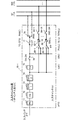
次に、本発明の一実施例のデジタルミキサの構成を図1を参照し説明する。
図1において2はタッチパネルであり、バスライン12を介して供給された表示情報に基づいてユーザに各種画面を表示するディスプレイと、このディスプレイの表面に貼付され、ユーザの指で押下されると、その旨および押下位置を検出するタッチスクリーンとから構成されている。タッチパネル2内のディスプレイは、例えば「1024×768」程度の解像度を有するフラットパネルディスプレイによって構成されている。4は表示器・操作子群であり、後述する操作パネル30上の各部に配置される各種のノブ、スイッチおよびLEDキーから構成されている。LEDキーに内蔵されたLEDの点滅状態はバスライン12を介して設定される。また、ノブ、スイッチおよびLEDキー等の操作状態はバスライン12を介して出力される。
1. Hardware configuration of the embodiment
1.1. Overall Configuration Next, the configuration of a digital mixer according to an embodiment of the present invention will be described with reference to FIG.
In FIG. 1,
6は電動フェーダ群であり、操作者の操作に基づいて各入出力チャンネルの信号レベルを調節する。さらに、電動フェーダ群6は、バスライン12を介して操作コマンドが供給されると、その操作位置が自動設定されるように構成されている。10は波形I/O部であり、アナログ音声信号またはデジタル音声信号を入出力する。本実施例においては、各種音声信号のミキシング処理・効果処理等は全てデジタル処理により実行される。しかし、外部から入力される音声信号および外部に出力すべき音声信号はデジタル、アナログ信号の双方が考えられる。このため、波形I/O部10においては、アナログ信号とデジタル信号間の変換、複数種類のデジタル信号相互間の変換等の処理が行われる。次に、8は信号処理部であり、一群のDSP(デジタル・シグナル・プロセッサ)によって構成されている。信号処理部8は、波形I/O部10を介して供給されたデジタル音声信号に対してミキシング処理や効果処理を施し、その結果を波形I/O部10に出力する。
An
14はコンピュータI/O部であり、外部のコンピュータとの間で各種制御情報を入出力する。16はその他I/O部であり、レコーダ等、各種の外部機器との間でタイムコードその他の情報を入出力する。18はCPUであり、後述する制御プログラムに基づいて、バスライン12を介して各部を制御する。20はフラッシュメモリであり、その内部のプログラム領域には上記制御プログラムが記憶されている。22はRAMであり、CPU18のワークメモリとして使用される。
A computer I /
本実施例のデジタルミキサにおいては、現在の動作を制御する各種パラメータ(カレントデータ)がRAM22の所定領域(カレント領域)に記憶されている。すなわち、ユーザが表示器・操作子群4、電動フェーダ群6を操作することによりカレントデータの内容が更新され、また、該カレントデータに基づいて信号処理部10におけるミキシング処理や効果処理、タッチパネル2における表示状態、表示器・操作子群4内のLEDの点滅状態、電動フェーダ群6の各フェーダの位置などが制御される。このカレントデータは、RAM22の所定領域(シーン領域)に対してシーンデータとして随時ストアすることができ、またシーン領域に記憶されたシーンデータをカレント領域に随時リコールすることができる。
In the digital mixer of this embodiment, various parameters (current data) for controlling the current operation are stored in a predetermined area (current area) of the
1.2.ミキシングアルゴリズム構成
次に、信号処理部8等において実現されるアルゴリズムの内容を図2を参照し説明する。なお、当該アルゴリズムは信号処理部8に設定されるプログラムによって実現されるものであり、該プログラムは、CPU18の制御の下、フラッシュメモリ20等から信号処理部8にロードされる。図2において51はアナログ入力部であり、マイクレベルまたはラインレベルのアナログ音声信号を受信すると、これをデジタル音声信号に変換し、信号処理部8に供給する。52はデジタル入力部であり、デジタル音声信号を受信すると、これを信号処理部8内部のフォーマットに変換する。66はアナログ出力部であり、信号処理部8から供給されたデジタル音声信号をアナログ音声信号に変換し外部に出力する。68はデジタル出力部であり、信号処理部8から供給された内部フォーマットのデジタル音声信号を所定フォーマット(AES/EBU,ADAT,TASCAM等)のデジタル音声信号に変換し出力する。
1.2. Mixing Algorithm Configuration Next, the details of the algorithm realized in the
以上述べた構成は、信号処理部8とは別体のハードウエアである波形I/O部10およびここに介挿される各種カードにより実現されているが、上記以外の構成は信号処理部8において動作するプログラムによって実現されている。55は入力チャンネル調整部であり、操作パネル30上の電動フェーダおよびノブ等の操作子の操作に基づいて、「48」チャンネルの入力チャンネルに対して音量・音質等の調整を行う。54は入力パッチ部であり、入力部51,52等の複数の入力ポートから供給されたデジタル音声信号を、入力チャンネル調整部55内の任意の入力チャンネルに割り当てる。
The configuration described above is realized by the waveform I /
58はMIXバス群であり、「16」系統のMIXバスから構成されている。各MIXバスにおいては、各入力チャンネルのデジタル音声信号のうち当該MIXバスに供給されたものがミキシングされる。各入力チャンネルにおいては、音声信号をMIXバスに供給するか否かを各MIXバス毎に設定することができ、供給する場合には各MIXバスに対するセンドレベルやフェードモード(プリフェード/ポストフェード)等も系統毎に独立して設定することができる。56はステレオ出力バスであり、「1」系統のステレオ出力バス56から構成されている。ステレオ出力バス56の構成は上記MIXバスと同様であるが、「1」系統のステレオの音声信号は左右「2」系統の音声信号から構成されている。60はステレオ出力チャンネル部であり、該ステレオ出力バス56におけるミキシング結果のレベル調節および音質調節を行なう。62はMIX出力チャンネル部であり、上記各MIXバスにおけるミキシング結果のレベル調節および音質調節を行なう。64は出力パッチ部であり、ステレオ出力チャンネル部60およびMIX出力チャンネル部62の出力信号を、各出力部66,68の任意のポートに割り当てる。
次に、入力チャンネル調整部55におけるアルゴリズム構成の詳細を図3を参照し説明する。図3において55−iは第i入力チャンネル調整部であり、第i入力チャンネル(1≦i≦48)における音質・音量調整を行う。その内部において71はアッテネータ部であり、入力された音声信号を減衰させる。72はイコライザ部であり、「4」バンドのパラメトリックイコライザ等により、音声信号の周波数特性を調節する。73,74は第1および第2ダイナミックス調整部であり、該音声信号に対して、コンプレッサ処理、ゲート処理等を行う。75は音量調整部であり、第i入力チャンネルの音声信号のゲインを調節する。76はオンオフ切換部であり、第i入力チャンネル全体のオン/オフ状態を切り換える。77はステレオセンドオンオフ切換部であり、第i入力チャンネルの音声信号をステレオ出力バス56に供給するか否かを切り換える。78はPAN設定部であり、該音声信号をステレオ出力バス56に供給する際の左右の音量バランスを設定する。
Next, details of the algorithm configuration in the input
80−1〜80−16は信号切換部であり、第i入力チャンネルから「16」系統のMIXバスに各々出力され得る音声信号をフェードモードに応じて切り換える。すなわち、フェードモードが「プリフェード」に設定されると、第2ダイナミックス調整部74の出力信号が選択され、「ポストフェード」に設定されるとオンオフ切換部76の出力信号が選択される。82−1〜82−16はセンドレベル調節部であり、各MIXバスに出力する信号のゲインすなわちセンドレベルを調節する。84−1〜84−16はセンドオンオフ切換部であり、各MIXバスに対する音声信号供給のオン/オフ状態を設定する。
Reference numerals 80-1 to 80-16 denote signal switching units, which switch audio signals that can be output from the i-th input channel to the "16" MIX buses according to the fade mode. That is, when the fade mode is set to “prefade”, the output signal of the second
1.3.パネル構成
1.3.1.パネル全体構成
次に、本実施例のデジタルミキサの操作パネル30の構成を図4を参照し説明する。この操作パネル30は、左セクション30aと、中央セクション30bと、右セクション30cとから構成されている。左セクション30aの内部において31〜34は入力チャンネルストリップ部であり、第1〜第32入力チャンネルのゲイン等を調節するチャンネルストリップが順次「8」チャンネルづつ設けられている。また、右セクション30cの内部において35,36は入力チャンネルストリップ部であり、第33〜第48入力チャンネルのゲイン等を調節するチャンネルストリップが順次「8」チャンネルづつ設けられている。37はステレオ出力チャンネルストリップ部であり、ステレオ出力チャンネル部60の左右のゲイン等を調節する一対のチャンネルストリップから構成されている。
1.3. Panel configuration
1.3.1. Next, the configuration of the
また、中央セクション30bの内部においてほぼ中央部には、上述したタッチパネル2が設けられている。38はレベルメータ部であり、各部の音声信号レベルを表示する複数のレベルメータから構成されている。40はパラメータ操作部であり、詳細なパラメータ等を設定するために選択された一の入出力チャンネルである「選択チャンネル」に対して、パラメータ等を調整する複数の操作子等から構成されている。ところで、本実施例のデジタルミキサの入出力チャンネルは、複数の「グループ」に分類されているので、このグループについて説明しておく。まず、入力チャンネル数は「48」であるが、これらは「8」チャンネルづつの「6」グループに分類されている。また、MIX出力チャンネル数は「16」であるが、これらは「8」チャンネルづつの「2」グループに分類されている。また、ステレオ出力チャンネルは左右一組の「1」チャンネルであるが、これも「1」グループを構成する。すなわち、入出力チャンネルは全体で「9」グループから構成されている。
In addition, the
46はグループ選択部であり、上記グループの何れかを選択する複数のスイッチによって構成されている。42は割当チャンネルストリップ部であり、グループ選択操作部46によって選択されたグループに属するチャンネルのゲイン等を調節するものである。また、タッチパネル2においては、選択されたグループに属するチャンネルについて、詳細な状態が表示される。44はシーン操作部であり、シーン番号の設定、シーンのストア、リコール等の操作を行うスイッチ等によって構成されている。
A
47,48はブックマークスイッチであり、タッチパネル2に現在表示されている画面をブックマーク登録し、あるいは既にブックマーク登録された画面を呼び出すものである。本実施例では「2」個のブックマークスイッチ47,48が設けられているため、ブックマークは最大「2」個まで設定することができる。49はミュート操作部であり、「8」のミュートグループに対応する「8」個のミュートボタンがその内部に配列されている。各ミュートグループには予め一または複数の入出力チャンネルが割り当てられており、ミュートボタンのうち何れかが押下されると、対応するミュートグループに属する入出力チャンネルの音量が連動して無音状態に設定され、該入出力チャンネルに係るフェーダが操作パネル30上に存在するときは、そのフェーダの操作位置も無音位置まで駆動される。
47 and 48 are bookmark switches for bookmarking the screen currently displayed on the
1.3.2.シーン操作部44の詳細構成
次に、操作パネル30上における要部の詳細構成について説明する。まず、図5(a)を参照しシーン操作部44の詳細構成を説明する。図5(a)において44−5はシーン番号表示部であり、ストア/リコールの対象となるシーン番号を表示する。44−2,3はアップダウンボタンであり、該シーン番号をインクリメント/デクリメントする。44−1はストアボタンであり、シーン番号表示部44−5に表示されている番号のシーンデータとして、カレントデータの内容をストアする。また、44−4はリコールボタンであり、シーン番号表示部44−5に表示されている番号のシーンデータをリコールし、カレントデータとして反映させる。
1.3.2. Detailed Configuration of
1.3.3.グループ選択操作部46の詳細構成
次に、図5(b)を参照しグループ選択操作部46の詳細構成を説明する。図5(b)において46−1〜46−6は入力チャンネル選択キーであり、入力チャンネルに係る「6」グループのうち何れかを選択するものである。46−7,46−8はMIX出力チャンネル選択キーであり、MIX出力チャンネルに係る「2」グループのうち何れかを選択するものである。46−9はステレオ出力チャンネル選択キーであり、ステレオ出力チャンネルのグループを選択するものである。ここで、入力チャンネル選択キー46−1〜46−6に対応するグループは、各々図4における入力チャンネルストリップ部31〜36に対応するグループである。そして、操作パネル30上におけるこれら入力チャンネルストリップ部31〜36の物理的な位置関係と、同一の位置関係で入力チャンネル選択キー46−1〜46−6が配列されていることが解る。
1.3.3. Detailed Configuration of Group
ステレオ出力チャンネル選択キー46−9も同様であり、図4においてステレオ出力チャンネルストリップ部37は入力チャンネルストリップ部35の左側に設けられているから、対応するステレオ出力チャンネル選択キー46−9も入力チャンネル選択キー46−5の左側に設けられている。一方、MIX出力チャンネルに係るグループについては、操作パネル30上には専用のチャンネルストリップ部は設けられていない。そこで、これらMIX出力チャンネルのグループについては、グループ選択操作部46のほぼ中央部分に集中して、対応するMIX出力チャンネル選択キー46−7,46−8が設けられている。なお、グループ選択操作部46内の各要素の符号は「46−g」(gは1〜9自然数)の形式で表されている。この値「g」は、各グループの識別番号として後述する処理において用いられる。
The same applies to the stereo output channel selection key 46-9, and since the stereo output
1.3.4.割当チャンネルストリップ部42の詳細構成
次に、図6(a)を参照し、割当チャンネルストリップ部42の詳細構成を説明する。割当チャンネルストリップ部42は、同様の構成を有する「8」個のチャンネルストリップを横方向に配列して成るものである。左端のチャンネルストリップ内において501はノブであり、アッテネータ部71における減衰率の設定、センドレベル調節部82−1〜82−16におけるセンドレベルの設定等、種々の目的のために用いられる。このため、ノブ501は無限回転型になっている。すなわち、ノブ501が操作されると、その操作前後の回転角度に応じて、対応するパラメータの量が設定されることになる。502はSELキーであり、各チャンネルストリップに係るチャンネルを選択チャンネルに設定するために用いられる。503はCUEキーであり、該チャンネルの音声信号をモニタするために用いられる。504はレベルメータであり、複数のLEDによって構成され該チャンネルの出力レベルを表示する。505はオン/オフキーであり、オンオフ切換部76の状態を制御する。506は電動フェーダであり、音量調整部75におけるゲインを調節する。
1.3.4. Detailed Configuration of Allocated
1.3.5.入力チャンネルストリップ部31〜36の詳細構成
次に、図6(b)を参照し、入力チャンネルストリップ部31〜36の詳細構成を説明する。各入力チャンネルストリップ部31〜36は、各々、同様の構成を有する「8」個のチャンネルストリップを横方向に配列して成るものである。左端のチャンネルストリップ内において512はSELキー、513はCUEキー、514はレベルメータ、515はオン/オフキー、516は電動フェーダであり、上記割当チャンネルストリップ部42内の構成要素502〜506と同様の機能を有する。換言すれば、割当チャンネルストリップ部42内のノブ501に対応するものが入力チャンネルストリップ部31〜34には設けられていないことになる。従って、ある入力チャンネルに対してノブ501によって調整可能なパラメータを調整するためには、グループ選択操作部46において該入力チャンネルの属するグループを選択し、割当チャンネルストリップ部42に当該グループの状態を反映させるとよい。
1.3.5. Detailed Configuration of Input
2.表示画面の例
2.1.背景ページ100
次に、タッチパネル2のディスプレイにおける各種表示画面の例を説明する。
まず、図7は、グループが選択された場合等に表示される背景ページ100の表示例である。図7において101〜108はチャンネルストリップ部であり、当該グループに属する「8」チャンネルの各々に対応して表示される。130は共通部であり、選択されたグループにかかわらず表示される。チャンネルストリップ部101の内部において110は表題部であり、該チャンネルストリップ部101に係る入出力チャンネルのチャンネル番号および短縮チャンネル名(ショートネーム)を表示する。
2. Example of display screen
2.1.
Next, examples of various display screens on the display of the
First, FIG. 7 is a display example of the
ここで、チャンネルストリップ部101〜108に係るチャンネルの中に選択チャンネルが含まれている場合は、当該チャンネルについては表題部110の表示色が他のチャンネルとは異なるように表示される(図7においてはハッチングで表記する)。これを「表題部カーソル」という。112は入力ゲイン表示部であり、当該チャンネルに対応する入力ポートのゲイン等の設定状態、すなわち図2における入力パッチ部54を介して当該チャンネルに接続されているアナログ入力部51またはデジタル入力部52内の入力ポートに設定されているゲイン等の設定状態の概要を表示する。特に、入力ゲイン表示部112にはノブ画像が表示され、これによって該入力ポートにおけるゲインが表示される。114はインサーションエフェクト表示部であり、例えば当該チャンネルのアッテネータ部71とイコライザ部72との間にインサーションエフェクト、グラフィックイコライザ等が挿入されているか否か等を表示する。
Here, when the selected channel is included in the channels related to the
116はイコライザ表示部であり、当該チャンネルのイコライザ部72によって設定された特性の概要を、その内部に設けられた小型のグラフによって表示する。118は第1ダイナミックス表示部、120は第2ダイナミックス表示部であり、各々ダイナミックス調整部73,74において設定された特性の概要を表示する。122はセンドレベル表示部であり、センドレベル調節部82−1〜82−16の数に等しい「16」個のノブ画像によって構成され、これらのセンドレベルを表示する。また、これらノブ画像の一部は、ダークアウト(図上では破線で示す)される場合がある。これは、対応するセンドオンオフ切換部84−1〜84−16がオフ状態に設定されていることを意味する。124はステレオ出力表示部であり、当該チャンネルのステレオセンドオンオフ切換部77およびPAN設定部78の設定状態をノブ画像等によって表示する。126はチャンネル名表示部であり、当該チャンネルのチャンネル名(ロングネーム)を表示する。
上述したように、入力ゲイン表示部112、センドレベル表示部122、ステレオ出力表示部124にはノブ画像が表示されているが、このうち任意のノブ画像をユーザが指で押下すると、その押下されたノブ画像と、各チャンネルストリップ部101〜108内における同一位置のノブ画像とに対して、図8に示すような「8」個のノブ画像カーソル150が表示される。このノブ画像カーソル150は、そのカーソル位置に係るパラメータが、割当チャンネルストリップ部42内の「8」個のノブ501によって調整可能になっていることを示す。これにより、ノブ501に対して様々な機能を割り当てることが可能になっているのである。
As described above, knob images are displayed on the input
上述した各表示部112〜124には、各々対応する詳細設定ウィンドウを表示させることができる。これら詳細設定ウィンドウにおいては、各表示部112〜124において表示されていない詳細なパラメータが表示されるとともに、これらパラメータを編集することが可能になっている。詳細設定ウィンドウを表示させる方法は、各表示部112〜124のうちノブ画像が含まれているものと含まれていないものとで異なる。すなわち、ノブ画像が含まれている表示部が最初に押下されると、上述したように押下位置のノブ画像にノブ画像カーソル150が表示される。このノブ画像カーソル150が表示されているノブ画像のうち何れかをもう一度押下すると、背景ページ100の上に詳細設定ウィンドウが表示されるのである。一方、ノブ画像が含まれていない表示部においては、単にその表示部を押下すると、対応する詳細設定ウィンドウが直ちに表示されることになる。
A corresponding detailed setting window can be displayed on each of the
図7に戻り、共通部130の内部において132〜142は各種機能ボタンであり、デジタルミキサが有する各種機能に対応付けられている。そして、何れかのボタンが押下されると、対応する詳細設定ウィンドウが表示される。これら各種機能ボタン132〜142に対応する詳細設定ウィンドウは、特に「チャンネル」には関連しないものである。144はメータ部であり、ステレオ出力チャンネル等の音声出力レベルを表示する。146は選択チャンネル指定部であり、現在の選択チャンネルを表示するとともに、その両端に設けられたスクロールボタン146a,146bを押下することにより、選択チャンネルを変更することができる。148はシーン番号表示部であり、現在のシーン番号を表示する。
Returning to FIG. 7, 132 to 142 are various function buttons in the
ところで、本実施例にいう「詳細設定ウィンドウ」は、各表示部112〜124、各種機能ボタン132〜142、またはノブ画像カーソル150に対する押下操作に応じて表示されるポップアップウィンドウであって、ミキシングアルゴリズム等のパラメータの詳細を表示・設定するためのポップアップウィンドウである。従って、例えばデータをセーブしようとしたときなどに表示される、"OK"ボタンや"CANCEL"ボタンなどを伴ってユーザに実行確認を求めるようなポップアップウィンドウ等の単なる確認用のウィンドウは、本実施例における「詳細設定ウィンドウ」には含まれない。
Incidentally, the “detail setting window” referred to in the present embodiment is a pop-up window that is displayed in response to a pressing operation on each of the
2.2.ダイナミックス詳細設定ウィンドウ200
以下、上述した詳細設定ウィンドウのうちの数例を説明する。
図7の背景ページ100において、何れかのチャンネルストリップ部101〜108の第1ダイナミックス表示部118が押下されると、図9に示す第1ダイナミックス詳細設定ウィンドウ200がタッチパネル2に表示される。その際、背景ページ100はダークアウト(図上では破線で示す)される。ウィンドウ200はタイトルバー210と、各種画像が表示されるフィールド部220とから成る。フィールド部220の内部において222,224,226は種別選択ボタンであり、何れかが択一的に選択され点灯状態になる(図上では点灯をハッチングで示す)。250は特性グラフ部であり、対応する第1ダイナミックス調整部73の入出力レベル特性を折れ線グラフによって表示する。246はオン/オフボタンであり、ダイナミックス特性のオン/オフ状態を設定する。なお、オフ状態になると、入出力特性がゲイン一定のリニアな状態になる。
2.2. Dynamics detailed setting
Hereinafter, several examples of the above-described detailed setting window will be described.
When the first
228〜242は「8」個のノブ画像であり、第1ダイナミックス調整部73における各種パラメータの値を表示する。ここで、ノブ画像228〜242のうち何れかを押下すると、これらノブ画像228〜242に対して、ノブ画像カーソル150(図8参照)が重ねて表示される。これにより、対応するパラメータが割当チャンネルストリップ部42内の「8」個のノブ501によって調整可能になる。ところで、本実施例においては、ノブ画像228〜242のうちノブ画像228〜236は、実際に「閾値」、「レート」、「アタック」、「ホールド」、「ディケイ」、「レンジ」などのパラメータの値の表示等の機能を有しているが、ノブ画像238,240,242はダミーのノブ画像であって、特に機能は有していない。これは、不要なノブ画像が含まれていたとしても、「8」個のノブ画像を横方向に配列することにより、これらノブ画像と「8」個のノブ501との対応関係をユーザが容易に把握できるようにしたものである。なお、ダミーのノブ画像は表示しないようにしてもよい。
2.3.イコライザ詳細設定ウィンドウ300
図7の背景ページ100において、何れかのチャンネルストリップ部101〜108のイコライザ表示部116が押下されると、図10に示すイコライザ詳細設定ウィンドウ300がタッチパネル2に表示される。ウィンドウ300はタイトルバー310と、各種画像が表示されるフィールド部320とから成る。フィールド部320の内部において326は特性表示部であり、対応するイコライザ部72の周波数特性をグラフによって表示する。328はフラットボタンであり、該特性を強制的にフラットにする。329はオン/オフボタンであり、イコライザ部72のオン/オフ状態を設定する。なお、オフ状態になると、入出力周波数特性はフラットな状態になる。330はレベル表示部であり、イコライザ部72に入出力される信号レベルを表示する。332はアッテネータノブ画像であり、アッテネータ部71に設定されている減衰率を表示する。
2.3. Equalizer detailed setting
When the
331はハイパスフィルタオン/オフボタンであり、ハイパスフィルタのオン/オフ状態を設定・表示する。334はハイパスフィルタ・ノブ画像であり、イコライザ部72に含まれるハイパスフィルタのカットオフ周波数を表示する。336〜360はパラメトリックイコライザ用のノブ画像である。イコライザ部72には、低音部(LOW)、中低音部(LOW-MID)、中高音部(HIGH-MID)および高音部(HIGH)の「4」バンドのパラメトリックイコライザが内蔵されており、各バンド毎に、中心周波数、ゲインおよびQ(鋭さ)のパラメータを設定することができる。そこで、合計「12」個のノブ画像がパラメトリックイコライザ用に表示されているのである。
ここで、ノブ画像332〜346のうち何れかを押下すると、これらノブ画像332〜346に対して、ノブ画像カーソル150(図8参照)が重ねて表示される。これにより、対応するパラメータが割当チャンネルストリップ部42内の「8」個のノブ501によって調整可能になる。また、ノブ画像348〜360のうち何れかを押下すると、これらノブ画像348〜360に加えて、アッテネータノブ画像332およびハイパスフィルタ・ノブ画像334にノブ画像カーソル150が重ねて表示される。すなわち、何れのノブ画像が押下されたとしても、アッテネータノブ画像332およびハイパスフィルタ・ノブ画像334には、常にノブ画像カーソル150が重ねて表示されることになる。これは、表示されるノブ画像カーソル150の数を常に「8」個にしておくことにより、対応する「8」個のノブ画像と、「8」個のノブ501との対応関係をユーザが容易に把握できるようにしたものである。また、調整頻度の高いパラメータに係るノブ画像に対して常にノブ画像カーソル150を表示しておくことにより、ノブ画像カーソル150の位置を切り替える手間が省け、操作性が向上するという利点も生じる。
Here, when any of the
2.4.センドレベル詳細設定ウィンドウ400
図7の背景ページ100において、各センドレベル表示部122内の「第4MIXバス」に対応する位置にノブ画像カーソル150が表示されている場合において、ユーザが何れかのノブ画像カーソル150を押下すると、図11に示すセンドレベル詳細設定ウィンドウ400がタッチパネル2に表示される(背景ページ100は図示略)。ウィンドウ400はタイトルバー410と、各種画像が表示されるフィールド部420とから成る。ここで、タイトルバー410に表示されている「MIX4 SEND」とは、「第4MIXバスに対する、各入力チャンネルのセンドレベル等を調整する」という意味である。フィールド部420においては、「1」グループに属する「8」の入力チャンネルから第4MIXバスに対するセンドレベル等の表示を行うチャンネル対応部451〜458が設けられている。440,442は選択ボタンであり、当該ウィンドウ400での調整対象になるMIXバスの番号を増減する。そして、新たなMIXバスの選択に応じて、タイトルバー410、後述する表示・設定部424,426、後述するノブ画像428,430等の表示が更新される。
2.4. Send level
When the
チャンネル対応部451の内部において422はチャンネル番号表示部であり、センドレベル等を表示するチャンネルのチャンネル番号を表示する。424はフェードモード表示・設定部であり、対応する入力チャンネルから第4MIXバスに対応する信号切換部80−4(図3参照)の状態がプリフェードの場合は点灯、ポストフェードの場合は消灯状態にされる。426はオン/オフ表示・設定部であり、センドオンオフ切換部84−4がオン状態の場合は点灯、オフ状態の場合は消灯される。また、ユーザがフェードモード表示・設定部424またはオン/オフ表示・設定部426を押下すると、フェードモードまたはオン/オフ状態が切り替えられる。428はPANノブ画像であり、左右の音量バランスを表示する。なお、各MIXバスはモノラルのバスであるが、奇数番号のMIXバスとその次の偶数番号のMIXバスとをペアに設定することにより、奇数番号のMIXバスを左チャンネル、偶数番号のMIXバスを右チャンネルとして使用することもできるため、かかる場合の音量バランスが表示されることになる。430はセンドレベルノブ画像であり、センドレベル調節部82−4に設定されたゲインを表示する。
In the
ここで、何れかのチャンネル対応部451〜458内のPANノブ画像428を押下すると、各チャンネル対応部451〜458内のこれら「8」個のPANノブ画像428に対して、ノブ画像カーソル150が重ねて表示される。同様に、何れかのセンドレベルノブ画像430を押下すると、「8」個のセンドレベルノブ画像430に対してノブ画像カーソル150が重ねて表示される。これにより、対応するパラメータが割当チャンネルストリップ部42内の「8」個のノブ501によって調整可能になる。センドレベルノブ画像430は、対応するセンドオンオフ切換部84−4がオフ状態であるときに、ダークアウト(図上では破線で示す)される。これにより、センドレベルの調節は可能であるが、実際には音声信号が第4MIXバスに出力されないことをユーザが認識しやすくなる。
Here, when the PAN knob image 428 in any one of the
3.実施例の動作
3.1.変数について
次に、本実施例の動作について説明するが、最初に各プログラムにおいて使用される主要な変数について説明しておく。
(1)グループ番号g:これは、グループ選択キー46−gのID番号(図5(b))を示す。各グループ選択キー46−gによって背景ページが特定されるため、グループ番号gは背景ページの識別番号としても使用される。
(2)背景ページ番号HP:これは、タッチパネル2に現在表示されている背景ページのグループ番号gである。
(3)選択チャンネル番号SC:現在の選択チャンネルの番号である。
(4)グループ固有選択チャンネルGSC(g):各グループには、選択チャンネル番号SCとは別に、グループ固有の選択チャンネルが規定される。グループ番号gに対応するグループ固有選択チャンネルを「GSC(g)」とする。
(5)ポップアップ番号PP:表示されている詳細設定ウィンドウ(ポップアップウィンドウ)の識別番号である。各詳細設定ウィンドウには、「1」以上のユニークな識別番号が付与されている。ポップアップ番号PPが「0」である場合は、「何れの詳細設定ウィンドウも表示されていない」ことを示す。
3. Operation of the embodiment
3.1. Variables Next, the operation of the present embodiment will be described. First, main variables used in each program will be described.
(1) Group number g: This indicates the ID number (FIG. 5B) of the group selection key 46-g. Since the background page is specified by each group selection key 46-g, the group number g is also used as the identification number of the background page.
(2) Background page number HP: This is the group number g of the background page currently displayed on the
(3) Selected channel number SC: This is the number of the currently selected channel.
(4) Group-specific selection channel GSC (g): In each group, a group-specific selection channel is defined in addition to the selection channel number SC. The group-specific selection channel corresponding to the group number g is “GSC (g)”.
(5) Pop-up number PP: This is the identification number of the displayed detailed setting window (pop-up window). Each detailed setting window is given a unique identification number of “1” or more. When the pop-up number PP is “0”, it indicates that “no detailed setting window is displayed”.
(6)ブックマークスイッチ番号b:これは、ブックマークスイッチ47,48の各識別番号である。
(7)ブックマーク・指定チャンネル番号BC(b):これは、ブックマークスイッチ番号bに対して、指定されたチャンネル番号である。チャンネル番号は「1」以上の値であるため、ブックマーク・指定チャンネル番号BC(b)が「0」の場合は「指定されたチャンネル番号が無い」ことを示す。
(8)ブックマーク・ポップアップ番号BPP(b):これは、ブックマークスイッチ番号bに対して指定された詳細設定ウィンドウのポップアップ番号PPである。何れの詳細設定ウィンドウも指定されていない場合は、ブックマーク・ポップアップ番号BPP(b)は「0」になる。
(9)ブックマーク・背景ページ番号BHP(b):これは、ブックマークスイッチ番号bに対して指定された背景ページの背景ページ番号HPである。
(6) Bookmark switch number b: This is an identification number of each of the bookmark switches 47 and 48.
(7) Bookmark / designated channel number BC (b): This is the channel number designated for the bookmark switch number b. Since the channel number is a value equal to or greater than “1”, when the bookmark / designated channel number BC (b) is “0”, it indicates that “the designated channel number does not exist”.
(8) Bookmark pop-up number BPP (b): This is the pop-up number PP of the detailed setting window designated for the bookmark switch number b. If no detailed setting window is designated, the bookmark pop-up number BPP (b) becomes “0”.
(9) Bookmark / background page number BHP (b): This is the background page number HP of the background page designated for the bookmark switch number b.
3.2.選択チャンネル指定イベント処理(図12)
まず、選択チャンネルの指定イベントが生じた場合の処理を図12を参照し説明する。なお、選択チャンネルの指定は、SELキー502,512(図6参照)が押下された場合、その他様々な場合に発生する。
図12において処理がステップSP30に進むと、選択チャンネル番号SCが、指定されたチャンネル番号i(例えば、SELキー502,512が押下された場合には、これに係るチャンネル番号)に変更される。次に、処理がステップSP32に進むと、選択チャンネル指定部146(図7参照)における表示が新たな選択チャンネル番号SCに応じて変更される。
3.2. Selected channel designation event processing (Fig. 12)
First, the processing when a specified channel designation event occurs will be described with reference to FIG. The selection of the selected channel occurs when the
When the processing proceeds to step SP30 in FIG. 12, the selected channel number SC is changed to the designated channel number i (for example, the channel number related to the case where the
次に、処理がステップSP34に進むと、現在の背景ページのチャンネルストリップ部101〜108には、選択チャンネル番号SCに係るものが表示されているか否かが判定される。ここで、「YES」と判定されると、処理はステップSP36に進み、表題部カーソルが選択チャンネル番号SCのチャンネルストリップ画像の表題部110(図7参照)に移動される。一方、ステップSP34において「NO」と判定されると、ステップSP36はスキップされる。
次に、処理がステップSP38に進むと、何れかの詳細設定ウィンドウが表示中であるか否かが判定される。
ここで「YES」と判定されると処理はステップSP40に進み、詳細設定ウィンドウに選択チャンネル番号SCに係るパラメータが表示される。例えば、図9に示した第1ダイナミックス詳細設定ウィンドウ200は、図示の状態では第4入力チャンネルの特性を表示しているが、仮に選択チャンネル番号SCが第8入力チャンネルに変更されたのであれば、該ウィンドウ200の内容は第8入力チャンネル係るものに更新されることになる。なお、共通部130内の各種機能ボタン132〜142によって表示される詳細設定ウィンドウは選択チャンネル番号SCには関係しないため、ステップSP40では実質的な処理は実行されない。
Next, when the process proceeds to step SP34, it is determined whether or not a channel related to the selected channel number SC is displayed in the
Next, when the process proceeds to step SP38, it is determined whether any detailed setting window is being displayed.
If “YES” is determined here, the process proceeds to step SP40, and the parameter relating to the selected channel number SC is displayed in the detailed setting window. For example, the first dynamics detailed setting
3.3.グループ選択イベント処理(図13(a))
次に、グループ選択操作部46(図5参照)内の何れかのグループ選択キー46−gのオンイベントが発生すると、図13(a)に示すグループ選択キー・オンイベント処理ルーチンが起動される。図において処理がステップSP2に進むと、現在の背景ページ番号HPに対するグループ固有選択チャンネルGSC(HP)の値が、現在の選択チャンネル番号SCに変更される。これは、後述する処理によって現在の背景ページが再びタッチパネル2に表示されたとき、現在の選択チャンネル番号SCを再び選択チャンネル番号SCとして復活させるためである。次に、処理がステップSP4に進むと、背景ページ番号HPが、押下されたグループ選択キー46−gに係るグループ番号gに変更される。また、ポップアップ番号PPが「0」に設定される。これは、現在表示されている背景ページに対して何らかの詳細設定ウィンドウが表示されていたとしても、新たに表示される背景ページに対して該詳細設定ウィンドウを継続的に表示させる必要性が乏しいためである。
3.3. Group selection event processing (Figure 13 (a))
Next, when an on event of any group selection key 46-g in the group selection operation unit 46 (see FIG. 5) occurs, the group selection key / on event processing routine shown in FIG. 13A is started. . In the figure, when the process proceeds to step SP2, the value of the group specific selection channel GSC (HP) for the current background page number HP is changed to the current selection channel number SC. This is to restore the current selected channel number SC as the selected channel number SC again when the current background page is displayed again on the
次に、処理がステップSP6に進むと、この新たな背景ページ番号HPに基づいて、タッチパネル2の表示が更新される。従って、背景ページは背景ページ番号HPに基づくものに更新される。但し、ポップアップ番号PPは「0」に設定されたから、詳細設定ウィンドウは全く表示されないことになる。次に、処理がステップSP8に進むと、グループ固有選択チャンネルGSC(HP)に係るSELキーが押下された場合と等価な擬似イベントが生成される。これにより、該グループ固有選択チャンネルGSC(HP)をチャンネル番号iとする選択チャンネル指定イベント処理(図12)が実行される。現在の背景ページに係るグループ固有選択チャンネルGSC(HP)は必ず存在するから、そのチャンネルストリップ画像に表題部カーソルが移動することになる。
Next, when the process proceeds to step SP6, the display on the
3.4.詳細設定ウィンドウ指定イベント処理(図13(b))
図7における各表示部112〜124、各種機能ボタン132〜142、またはノブ画像カーソル150が表示されているノブ画像の何れかが押下された場合には、詳細設定ウィンドウが表示されるが、かかる処理は図13(b)に示す詳細設定ウィンドウ指定イベント処理ルーチンによって実現される。図において処理がステップSP12に進むと、ポップアップ番号PPの値が、当該操作に対応する詳細設定ウィンドウの識別番号に設定される。次に、処理がステップSP14に進むと、何らかの詳細設定ウィンドウが既にタッチパネル2に表示中であるか否かが判定される。ここで「YES」と判定されると、処理はステップSP16に進み、既存の詳細設定ウィンドウが画面上から消去される。一方、ステップSP14において「NO」と判定されると、ステップSP16はスキップされる。次に、処理がステップSP18に進むと、背景ページ上にポップアップ番号PPに係る詳細設定ウィンドウが表示される。
3.4. Detailed setting window designation event processing (Figure 13 (b))
When any of the
次に、処理がSP19に進むと、詳細設定ウィンドウを表示させる操作がチャンネルに関係する操作であるのか否かが判定される。すなわち、チャンネルストリップ部101〜108内における何れかの表示部112〜124またはノブ画像カーソル150を押下する操作は、該チャンネルストリップ部に係るチャンネル番号iに関係する操作であり、共通部130内の各種機能ボタン132〜142の操作はチャンネルに関係しない操作である。ステップSP19において「YES」と判定されると、処理はステップSP20に進み、上記チャンネル番号iを引数として、上述した選択チャンネル指定イベント処理(図12)が実行される。ここで、現在の背景ページに係るグループ固有選択チャンネルGSC(HP)は必ず存在するから、そのチャンネルストリップ画像に表題部カーソルが移動し(ステップSP36)、表示された詳細設定ウィンドウには、上記選択チャンネル番号SCが反映されることになる(ステップSP40)。
Next, when the process proceeds to SP19, it is determined whether or not the operation for displaying the detailed setting window is an operation related to a channel. That is, the operation of pressing any one of the
ここで、上記ステップSP16について述べたように、本実施例では既存の詳細設定ウィンドウが存在する場合に新たな詳細設定ウィンドウを表示しようとすると、既存の詳細設定ウィンドウが消去される。ここに本実施例の特徴の一つがある。すなわち、複数の詳細設定ウィンドウが表示されると、タッチパネル2の画面上が雑然とし、操作がしにくくなるという問題が生じる。本実施例では新たな詳細設定ウィンドウを表示する際に既存の詳細設定ウィンドウを消去することにより、かかる問題を未然に防止したものである。
Here, as described for step SP16 above, in this embodiment, when an existing detailed setting window exists and an attempt is made to display a new detailed setting window, the existing detailed setting window is deleted. This is one of the features of this embodiment. That is, when a plurality of detailed setting windows are displayed, there is a problem that the screen of the
3.5.詳細設定ウィンドウ・クローズ処理(図13(c))
何れかの詳細設定ウィンドウが表示されているとき、ユーザがそのクローズボタン(ウィンドウ右上隅の「×」印のボタン)を押下し、あるいは背景ページの部分を押下すると、詳細設定ウィンドウをクローズすべく図13(c)に示す詳細設定ウィンドウ・クローズ処理ルーチンが起動される。図において処理がステップSP22に進むと、ポップアップ番号PPが「0」に設定される。そして、処理がステップSP24に進むと、背景ページ上に表示されている詳細設定ウィンドウが消去される。なお、詳細設定ウィンドウが表示されていた際には背景ページはダークアウトされていたが、詳細設定ウィンドウが消去されると、背景ページの表示状態も通常の(ダークアウトされていない)表示状態に戻される。
3.5. Detail setting window close processing (Figure 13 (c))
When any of the detailed setting windows is displayed, if the user presses the close button (the button marked with “X” in the upper right corner of the window) or the background page portion, the detailed setting window should be closed. The detailed setting window / close processing routine shown in FIG. 13C is started. When the processing proceeds to step SP22 in the figure, the pop-up number PP is set to “0”. When the processing proceeds to step SP24, the detailed setting window displayed on the background page is deleted. Note that when the detailed settings window was displayed, the background page was darked out, but when the detailed settings window was deleted, the background page display state also changed to the normal (not darkened) display state. Returned.
3.6.ノブ操作イベント(図13(d))
割当チャンネルストリップ部42(図6(a)参照)内のノブ501が操作されると、時計回り、または反時計回りの所定の単位角度の回転動作が実行される毎にその旨が検出され、図13(d)に示すノブ操作イベントルーチンが起動される。図において処理がステップSP26に進むと、当該ノブ501の操作量に応じて、ノブ画像カーソル150のある複数のノブ画像のうちの当該ノブ501に対応するノブ画像で表示されているパラメータが所定量だけ変更される。さらに、画面上においては、対応するノブ画像自体も時計回り、または反時計回りに回転される。従って、ノブ501をある程度回動させると、上記単位角度の回転毎に、本ルーチンが複数回繰り返して実行され、パラメータの変更とノブ画像の更新がノブ501の操作に連動して実行されることになる。
3.6. Knob operation event (Fig. 13 (d))
When the
3.7.ブックマークスイッチ・オフ操作イベント(図14)
次に、ブックマークスイッチ47,48のうち何れかが押下され、しかる後にオフされたときに起動されるブックマークスイッチ・オフ操作イベント処理の内容を図14を参照し説明する。図14において処理がステップSP50に進むと、当該ブックマークスイッチが長押しされたか否か、すなわち所定時間以上押下され続けたか否かが判定される。ここで「YES」と判定されると、処理はステップSP62に進み、選択チャンネルに関連する設定を行うための詳細設定ウィンドウがタッチパネル2のディスプレイに表示されているか否かが判定される。ここで「YES」と判定されると、処理はステップSP64に進み、「選択チャンネルの指定を含めますか?」というメッセージとともに、「YES」および「NO」ボタンを表示したダイアログが表示される。
3.7. Bookmark switch off operation event (Figure 14)
Next, the contents of the bookmark switch-off operation event process that is activated when any one of the bookmark switches 47, 48 is pressed and then turned off will be described with reference to FIG. In FIG. 14, when the process proceeds to step SP50, it is determined whether or not the bookmark switch has been pressed for a long time, that is, whether or not the bookmark switch has been pressed for a predetermined time or longer. If "YES" is determined here, the process proceeds to a step SP62 to determine whether or not a detailed setting window for performing settings related to the selected channel is displayed on the display of the
このダイアログにおいて「YES」または「NO」ボタンが押下されると、該ダイアログが閉じられ、処理はステップSP66に進む。ここでは、選択チャンネルの指定を含めるか否か、すなわち押下されたボタンが「YES」または「NO」のうち何れであるかが判定される。ここで、「YES」ボタンが押下された場合には、「YES」と判定され処理はステップSP68に進み、押下されたブックマークスイッチ47,48のブックマークスイッチ番号をbとして、ブックマーク・指定チャンネル番号BC(b)の値が選択チャンネル番号SCに変更される。一方、ステップSP66において「NO」と判定されると処理はステップSP70に進み、ブックマーク・指定チャンネル番号BC(b)の値が「0」に設定される。
When the “YES” or “NO” button is pressed in this dialog, the dialog is closed and the process proceeds to step SP66. Here, it is determined whether or not the designation of the selected channel is included, that is, whether the pressed button is “YES” or “NO”. Here, if the “YES” button is pressed, “YES” is determined, and the process proceeds to step
また、ステップSP62において「NO」と判定された場合には、上記ダイアログが表示されることなくブックマーク・指定チャンネル番号BC(b)は「0」に設定される。同様に、選択チャンネルに関連する設定を行うための詳細設定ウィンドウがタッチパネル2のディスプレイに表示されていない場合にはステップSP62において「NO」と判定され、ステップSP74において、ブックマーク・指定チャンネル番号BC(b)が「0」に設定される。これは、本実施例のデジタルミキサの仕様として、背景ページとして表示されている「8」チャンネル以外のチャンネルを選択チャンネルとして設定できるようになっていること、および、背景ページでは各グループ番号g毎に固有のグループ固有選択チャンネルGSC(g)を記憶するようになっていることによるものである。すなわち、背景ページのブックマークに対して選択チャンネルの指定を含めるとユーザに混乱を引き起こすおそれがあるため、これを防止できるようにしたものである。
If “NO” is determined in step SP62, the bookmark / designated channel number BC (b) is set to “0” without displaying the dialog. Similarly, when the detailed setting window for performing the setting related to the selected channel is not displayed on the display of the
次に、処理がステップSP72に進むと、ブックマーク・ポップアップ番号BPP(b)の値が、現在表示されている詳細設定ウィンドウのポップアップ番号PPに設定される。ここで、詳細設定ウィンドウが表示されていない場合には、ポップアップ番号PPは「0」であるから、ブックマーク・ポップアップ番号BPP(b)の値も「0」に設定されることになる。なお、単なる確認用のダイアログ等に対してはポップアップ番号PPは付与されないため、確認用のダイアログ等がブックマーク・ポップアップ番号BPP(b)として記憶されることはない。これにより、ブックマーク呼出し時においては、これら確認用のダイアログ等が表示されることを防止することができる。また、ステップSP72においては、ブックマーク・背景ページ番号BHP(b)の値が、現在の背景ページ番号HPに設定される。 Next, when the process proceeds to step SP72, the value of the bookmark pop-up number BPP (b) is set to the pop-up number PP of the detailed setting window currently displayed. Here, when the detailed setting window is not displayed, the pop-up number PP is “0”, so the value of the bookmark pop-up number BPP (b) is also set to “0”. Note that since a pop-up number PP is not given to a simple confirmation dialog or the like, the confirmation dialog or the like is not stored as a bookmark pop-up number BPP (b). As a result, when a bookmark is called, it is possible to prevent these confirmation dialogs and the like from being displayed. In step SP72, the value of the bookmark / background page number BHP (b) is set to the current background page number HP.
次に、ブックマークスイッチが長押しされなかった場合の処理を説明する。かかる場合は、ステップSP50において「NO」と判定され、処理はステップSP52に進む。ここでは、ブックマーク・ポップアップ番号BPP(b)として「0」以外の値が存在するか否か、すなわち表示すべき詳細設定ウィンドウが存在するか否かが判定される。ここで「YES」と判定されると、処理はステップSP54に進み、ブックマーク・ポップアップ番号BPP(b)に係る詳細設定ウィンドウがタッチパネル2に表示される。その際、タッチパネル2上の背景ページは変更されない。従って、ブックマークスイッチ番号bに対応して記憶されているブックマーク・背景ページ番号BHP(b)は、この場合には無視されることになる。一方、ステップSP52において「NO」と判定されると、処理はステップSP56に進み、ブックマーク・背景ページ番号BHP(b)に係る背景ページが、タッチパネル2に表示される。
Next, processing when the bookmark switch is not pressed for a long time will be described. In such a case, “NO” is determined in step SP50, and the process proceeds to step SP52. Here, it is determined whether there is a value other than “0” as the bookmark pop-up number BPP (b), that is, whether there is a detailed setting window to be displayed. If "YES" is determined here, the process proceeds to step SP54, and a detailed setting window related to the bookmark pop-up number BPP (b) is displayed on the
このように、ステップSP54において、現在の背景ページが保持されることも本実施例の特徴の一つである。すなわち、ブックマーク・背景ページ番号BHP(b)が記憶されている場合であっても、ブックマーク・ポップアップ番号BPP(b)が記憶されている場合には、ユーザはブックマーク・背景ページを表示することではなく、ブックマーク・ポップアップ番号BPP(b)に係る詳細設定ウィンドウを表示することを望んでいると考えられる。そこで、本実施例においては、現在の背景ページの上に当該詳細設定ウィンドウを表示することにより、ユーザの意図に反して背景ページが変更されてしまう事態を未然に防止しているのである。 As described above, it is also one of the features of this embodiment that the current background page is retained in step SP54. That is, even when the bookmark / background page number BHP (b) is stored, if the bookmark / pop-up number BPP (b) is stored, the user cannot display the bookmark / background page. The detailed setting window related to the bookmark pop-up number BPP (b) may be displayed. Therefore, in this embodiment, the detailed setting window is displayed on the current background page, thereby preventing a situation in which the background page is changed against the user's intention.
次に、処理がステップSP58に進むと、ブックマーク・指定チャンネル番号BC(b)が「0」以外の値であるか否かが判定される。ここで「YES」と判定されると、処理はステップSP60に進み、ブックマーク・指定チャンネル番号BC(b)に係るSELキーが押下された場合と等価な擬似イベントが生成される。これにより、ブックマーク・指定チャンネル番号BC(b)をチャンネル番号iとする選択チャンネル指定イベント処理(図12)が実行される。なお、ブックマーク・指定チャンネル番号BC(b)が「0」以外の値になるのは、ブックマーク登録の際に詳細設定ウィンドウが存在し、上述したステップSP68が実行された場合である。この場合には、上記ステップSP54を介して詳細設定ウィンドウが表示されているはずであるから、該詳細設定ウィンドウの表示対象チャンネルがブックマーク・指定チャンネル番号BC(b)に対応するものに変更される。 Next, when the process proceeds to step SP58, it is determined whether or not the bookmark / designated channel number BC (b) is a value other than “0”. If "YES" is determined here, the process proceeds to step SP60, and a pseudo event equivalent to the case where the SEL key related to the bookmark / designated channel number BC (b) is pressed is generated. As a result, the selected channel designation event process (FIG. 12) with the bookmark / designated channel number BC (b) as the channel number i is executed. The bookmark / designated channel number BC (b) has a value other than “0” when a detailed setting window exists at the time of bookmark registration and step SP68 described above is executed. In this case, since the detailed setting window should have been displayed via step SP54, the display target channel of the detailed setting window is changed to one corresponding to the bookmark / designated channel number BC (b). .
4.変形例
本発明は上述した実施例に限定されるものではなく、例えば以下のように種々の変形が可能である。
(1)上記実施例においては、CPU18上で動作する各種プログラムによって各種処理を実行したが、これらのプログラムのみをCD−ROM、フレキシブルディスク等の記録媒体に格納して頒布し、あるいは伝送路を通じて頒布することもできる。
Four. Modifications The present invention is not limited to the above-described embodiments, and various modifications can be made as follows, for example.
(1) In the above embodiment, various processes are executed by various programs operating on the
(2)上記実施例のステップSP64においては、選択チャンネルの指定を含めるか否かを確認するダイアログを表示したが、選択チャンネルの指定を含めるか否かの選択は、必ずしもダイアログによって行う必要はない。例えば、ブックマークスイッチ47,48の近傍にシフトスイッチを設け、ユーザが該シフトスイッチを押下しながらブックマークスイッチ47,48を押下したときには選択チャンネルの指定を含めることとし、シフトスイッチを押下することなくブックマークスイッチ47,48を押下したときには選択チャンネルの指定を含めないようにしてもよい。また、単独でブックマークスイッチ47,48が操作された場合には選択チャンネルの指定を含めないこととし、何れかのチャンネルのSELキーが押下された状態でブックマークスイッチ47,48が押下された場合には、当該チャンネルを選択チャンネルとして記憶しつつブックマーク登録するようにしてもよい。
(2) In step SP64 of the above-described embodiment, a dialog for confirming whether or not to include the designation of the selected channel is displayed. However, the selection of whether or not to include the designation of the selected channel is not necessarily performed by the dialog. . For example, a shift switch is provided in the vicinity of the bookmark switches 47 and 48, and when the user presses the
(3)また、上記実施例は、ブックマークスイッチ47,48を押下してブックマーク登録を行う際に選択チャンネルの指定を含めるか否かの選択を行ったが、ブックマークスイッチ47,48の各々に対して、「選択チャンネルの指定を含むか含まないか」を予め設定できるようにしてもよい。
(3) In the above embodiment, the
(4)また、上記ステップSP72においては、ブックマーク・ポップアップ番号BPP(b)とブックマーク・背景ページ番号BHP(b)とを共に記憶させたが、これらは必ずしも共に記憶させる必要はない。すなわち、後に実行されるステップSP52〜SP56においては、ブックマーク・ポップアップ番号BPP(b)が「0」以外の値であるか否かに基づいて、ブックマーク・ポップアップ番号BPP(b)に係る詳細設定ウィンドウ、またはブックマーク・背景ページ番号BHP(b)に係る背景ページのみが択一的に選択され表示される。従って、ステップSP72においては、該ステップ実行時のポップアップウィンドウのポップアップ番号PPが「1」以上であれば、該ステップ実行時のポップアップウィンドウのポップアップ番号PPのみをブックマーク・ポップアップ番号BPP(b)として記憶し、該ステップ実行時のポップアップウィンドウのポップアップ番号PPが「0」であれば、ブックマーク・背景ページ番号BHP(b)のみを記憶させることもできる。 (4) In step SP72, the bookmark / pop-up number BPP (b) and the bookmark / background page number BHP (b) are stored together. However, they need not be stored together. That is, in steps SP52 to SP56 to be executed later, a detailed setting window related to the bookmark pop-up number BPP (b) is determined based on whether or not the bookmark pop-up number BPP (b) is a value other than “0”. Alternatively, only the background page associated with the bookmark / background page number BHP (b) is alternatively selected and displayed. Accordingly, in step SP72, if the pop-up number PP of the pop-up window at the time of executing the step is “1” or more, only the pop-up number PP of the pop-up window at the time of executing the step is stored as the bookmark pop-up number BPP (b). If the pop-up number PP of the pop-up window at the time of executing the step is “0”, only the bookmark / background page number BHP (b) can be stored.
(5)また、上記ステップSP62、ステップSP74においては、背景ページがブックマーク登録される際にブックマーク・指定チャンネル番号BC(b)は必ず「0」に設定されたが、背景ページにをブックマーク登録する場合においても、ステップSP64〜SP70の処理を実行させ、ユーザの選択に応じて選択チャンネルの指定を含むブックマーク登録ができるようにしてもよい。 (5) In step SP62 and step SP74, the bookmark / designated channel number BC (b) is always set to “0” when the background page is registered as a bookmark, but the bookmark is registered in the background page. Even in such a case, the processing of steps SP64 to SP70 may be executed so that bookmark registration including designation of a selected channel can be performed in accordance with the user's selection.
2:タッチパネル(ディスプレイ)、4:表示器・操作子群、6:電動フェーダ群、8:信号処理部(信号処理手段)、10:波形I/O部、12:バスライン、14:コンピュータI/O部、16:その他I/O部、18:CPU(処理装置)、20:フラッシュメモリ、22:RAM(記憶手段)、30:操作パネル、30a:左セクション、30b:中央セクション、30c:右セクション、31〜36:入力チャンネルストリップ部、37:ステレオ出力チャンネルストリップ部、38:レベルメータ部、40:パラメータ操作部、42:割当チャンネルストリップ部、44:シーン操作部、44−1:ストアボタン、44−2,3:アップダウンボタン、44−4:リコールボタン、44−5:シーン番号表示部、46:グループ選択操作部、46−1〜46−6:入力チャンネル選択キー、46−7,46−8:MIX出力チャンネル選択キー、46−9:ステレオ出力チャンネル選択キー、47,48:ブックマークスイッチ、49:ミュート操作部、51:アナログ入力部、52:デジタル入力部、54:入力パッチ部、55:入力チャンネル調整部、55−i:第i入力チャンネル調整部、56:ステレオ出力バス、58:MIXバス群、60:ステレオ出力チャンネル部、62:MIX出力チャンネル部、64:出力パッチ部、66:アナログ出力部、68:デジタル出力部、71:アッテネータ部、72:イコライザ部、73:第1ダイナミックス調整部、74:第2ダイナミックス調整部、75:音量調整部、76:オンオフ切換部、77:ステレオセンドオンオフ切換部、78:PAN設定部、80−1〜80−16:信号切換部、82−1〜82−16:センドレベル調節部、84−1〜84−16:センドオンオフ切換部、100:背景ページ(背景画面)、101〜108:チャンネルストリップ部、110:表題部、112:入力ゲイン表示部(パラメータ表示部)、114:インサーションエフェクト表示部(パラメータ表示部)、116:イコライザ表示部(パラメータ表示部)、118:第1ダイナミックス表示部(パラメータ表示部)、120:第2ダイナミックス表示部(パラメータ表示部)、122:センドレベル表示部(パラメータ表示部)、124:ステレオ出力表示部(パラメータ表示部)、126:チャンネル名表示部、130:共通部、132〜142:各種機能ボタン、144:メータ部、146:選択チャンネル指定部、146a,146b:スクロールボタン、148:シーン番号表示部、150:ノブ画像カーソル、200:第1ダイナミックス詳細設定ウィンドウ、200:ウィンドウ、210:タイトルバー、220:フィールド部、222,224,226:種別選択ボタン、228〜242:ノブ画像、246:オン/オフボタン、250:特性グラフ部、300:イコライザ詳細設定ウィンドウ、300:ウィンドウ、310:タイトルバー、320:フィールド部、326:特性表示部、328:フラットボタン、329:オン/オフボタン、330:レベル表示部、331:ハイパスフィルタオン/オフボタン、332〜360:ノブ画像、400:センドレベル詳細設定ウィンドウ、400:ウィンドウ、410:タイトルバー、420:フィールド部、422:チャンネル番号表示部、424:フェードモード表示・設定部、426:オン/オフ表示・設定部、428:PANノブ画像、430:センドレベルノブ画像、440,442:選択ボタン、451〜458:チャンネル対応部、501:ノブ、502,512:SELキー、503:CUEキー、504:レベルメータ、505:オン/オフキー、506:電動フェーダ、513:CUEキー、514:レベルメータ、515:オン/オフキー、516:電動フェーダ。 2: Touch panel (display), 4: Display / operator group, 6: Electric fader group, 8: Signal processing unit (signal processing means), 10: Waveform I / O unit, 12: Bus line, 14: Computer I / O unit, 16: other I / O unit, 18: CPU (processing device), 20: flash memory, 22: RAM (storage means), 30: operation panel, 30a: left section, 30b: central section, 30c: Right section, 31 to 36: input channel strip section, 37: stereo output channel strip section, 38: level meter section, 40: parameter operation section, 42: assigned channel strip section, 44: scene operation section, 44-1: store Button, 44-2, 3: up / down button, 44-4: recall button, 44-5: scene number display section, 46: group Selection operation section, 46-1 to 46-6: input channel selection key, 46-7, 46-8: MIX output channel selection key, 46-9: stereo output channel selection key, 47, 48: bookmark switch, 49: Mute operation unit, 51: analog input unit, 52: digital input unit, 54: input patch unit, 55: input channel adjustment unit, 55-i: i-th input channel adjustment unit, 56: stereo output bus, 58: MIX bus Group: 60: stereo output channel section, 62: MIX output channel section, 64: output patch section, 66: analog output section, 68: digital output section, 71: attenuator section, 72: equalizer section, 73: first dynamics Adjustment unit, 74: second dynamics adjustment unit, 75: volume adjustment unit, 76: on / off switching unit, 77: stereosen ON / OFF switching unit, 78: PAN setting unit, 80-1 to 80-16: signal switching unit, 82-1 to 82-16: send level adjustment unit, 84-1 to 84-16: send on / off switching unit, 100: Background page (background screen), 101-108: channel strip section, 110: title section, 112: input gain display section (parameter display section), 114: insertion effect display section (parameter display section), 116: equalizer display section (Parameter display unit), 118: first dynamics display unit (parameter display unit), 120: second dynamics display unit (parameter display unit), 122: send level display unit (parameter display unit), 124: stereo output Display part (parameter display part), 126: Channel name display part, 130: Common part, 132-142: Various machines Function button, 144: meter section, 146: selected channel designation section, 146a, 146b: scroll button, 148: scene number display section, 150: knob image cursor, 200: first dynamics detail setting window, 200: window, 210 : Title bar, 220: Field part, 222, 224, 226: Type selection button, 228 to 242: Knob image, 246: On / off button, 250: Characteristic graph part, 300: Equalizer detailed setting window, 300: Window, 310: Title bar, 320: Field portion, 326: Characteristic display portion, 328: Flat button, 329: On / off button, 330: Level display portion, 331: High pass filter on / off button, 332-360: Knob image, 400: Send level detailed setting window , 400: window, 410: title bar, 420: field section, 422: channel number display section, 424: fade mode display / setting section, 426: on / off display / setting section, 428: PAN knob image, 430: Send level knob image, 440, 442: Select button, 451-458: Channel corresponding part, 501: Knob, 502, 512: SEL key, 503: CUE key, 504: Level meter, 505: On / off key, 506: Electric Fader, 513: CUE key, 514: Level meter, 515: On / off key, 516: Electric fader.
Claims (4)
該動作データに基づいてミキシング処理を行う信号処理手段と、
ディスプレイと、
任意の背景画面を選択する背景画面選択操作を検出すると、選択された背景画面を前記ディスプレイに表示させる背景画面選択手段と、
前記背景画面の上に何れかの詳細設定ウィンドウを表示させる詳細設定指示操作を検出すると、前記ディスプレイに表示された前記背景画面上に、指示された詳細設定ウィンドウを表示させる詳細設定ウィンドウ表示手段と、
何れかの前記パラメータの値を変更する値変更操作を検出すると、前記動作データのうちの、表示中の前記背景画面または前記詳細設定ウィンドウに表示されているパラメータの値を変更するパラメータ制御手段と、
所定のブックマーク登録操作を検出すると、その時点で何れかの前記詳細設定ウィンドウが表示されていれば、少なくともその詳細設定ウィンドウを示す指定データを前記記憶手段に保持する一方、何れの詳細設定ウィンドウも表示されていなければ、少なくともその時点で表示されている前記背景画面を示す指示データを前記記憶手段に保持するブックマーク登録手段と、
所定のブックマーク呼出操作を検出すると、前記記憶手段に保持されている前記指定データが示す画面を前記ディスプレイに表示させるブックマーク呼出手段であって、該指定データが前記詳細設定ウィンドウを示すデータを含む場合は、その時点で表示されている背景画面の上に該詳細設定ウィンドウを表示させる一方、該指定データが何れの詳細設定ウィンドウを示すデータを含まず、かつ、該指示データが何れかの背景画面を示すデータを含む場合は、該背景画面を表示させるブックマーク呼出手段と
を具備することを特徴とするデジタルミキサ。 Storage means for storing operation data comprising a plurality of parameters for controlling signal processing;
Signal processing means for performing mixing processing based on the operation data;
Display,
When a background screen selection operation for selecting an arbitrary background screen is detected, background screen selection means for displaying the selected background screen on the display; and
Detailed setting window display means for displaying an instructed detailed setting window on the background screen displayed on the display when a detailed setting instruction operation for displaying any of the detailed setting windows on the background screen is detected. ,
A parameter control means for changing a value of a parameter displayed on the background screen or the detailed setting window of the operation data when detecting a value change operation for changing a value of any one of the parameters; ,
When a predetermined bookmark registration operation is detected, if any of the detailed setting windows is displayed at that time, at least the designated data indicating the detailed setting window is held in the storage unit, while any of the detailed setting windows is also displayed. If not displayed, bookmark registration means for holding instruction data indicating at least the background screen displayed at that time in the storage means;
When a predetermined bookmark calling operation is detected, bookmark calling means for causing the display to display a screen indicated by the designated data held in the storage means, wherein the designated data includes data indicating the detailed setting window Displays the detailed setting window on the background screen displayed at that time, while the designated data does not include data indicating any detailed setting window, and the instruction data is any background screen. And a bookmark calling means for displaying the background screen when the data is included.
をさらに有することを特徴とする請求項1記載のデジタルミキサ。 2. The digital mixer according to claim 1, further comprising: detailed setting window deleting means for deleting a detailed setting window displayed on the display when a predetermined detailed setting window deleting operation is detected.
前記詳細設定指示操作は、前記複数のパラメータ表示部のうちの何れかに対する操作であり、
前記詳細設定ウィンドウ表示手段によって表示される詳細設定ウィンドウは、操作されたパラメータ表示部に表示されているパラメータを設定するための操作部を有するウィンドウである
ことを特徴とする請求項1または2記載のデジタルミキサ。 The background screen has a plurality of parameter display units for displaying parameters set for the signal processing means,
The detailed setting instruction operation is an operation for any one of the plurality of parameter display units,
The detailed setting window displayed by the detailed setting window display means is a window having an operation unit for setting a parameter displayed in the operated parameter display unit. Digital mixer.
任意の背景画面を選択する背景画面選択操作を検出すると、選択された背景画面を前記ディスプレイに表示させる背景画面選択過程と、
前記背景画面の上に何れかの詳細設定ウィンドウを表示させる詳細設定指示操作を検出すると、前記ディスプレイに表示された前記背景画面上に、指示された詳細設定ウィンドウを表示させる詳細設定ウィンドウ表示過程と、
何れかの前記パラメータの値を変更する値変更操作を検出すると、前記動作データのうちの、表示中の前記背景画面または前記詳細設定ウィンドウに表示されているパラメータの値を変更するパラメータ制御過程と、
所定のブックマーク登録操作を検出すると、その時点で何れかの前記詳細設定ウィンドウが表示されていれば、少なくともその詳細設定ウィンドウを示す指定データを前記記憶手段に保持する一方、何れの詳細設定ウィンドウも表示されていなければ、少なくともその時点で表示されている前記背景画面を示す指示データを前記記憶手段に保持するブックマーク登録過程と、
所定のブックマーク呼出操作を検出すると、前記記憶手段に保持されている前記指定データが示す画面を前記ディスプレイに表示させるブックマーク呼出過程であって、該指定データが前記詳細設定ウィンドウを示すデータを含む場合は、その時点で表示されている背景画面の上に該詳細設定ウィンドウを表示させる一方、該指定データが何れの詳細設定ウィンドウを示すデータを含まず、かつ、該指示データが何れかの背景画面を示すデータを含む場合は、該背景画面を表示させるブックマーク呼出過程と
を前記処理装置に実行させることを特徴とするプログラム。 Digital mixer having a processing device, storage means for storing operation data composed of a plurality of parameters for controlling signal processing, signal processing means for performing mixing processing based on the operation data, and a display controlled by the processing device A program that applies to
When a background screen selection operation for selecting an arbitrary background screen is detected, a background screen selection process for displaying the selected background screen on the display; and
A detailed setting window display process for displaying the specified detailed setting window on the background screen displayed on the display when detecting a detailed setting instruction operation for displaying any detailed setting window on the background screen; ,
A parameter control process for changing a value of a parameter displayed on the background screen or the detailed setting window of the operation data when detecting a value change operation for changing a value of any one of the parameters; ,
When a predetermined bookmark registration operation is detected, if any of the detailed setting windows is displayed at that time, at least the designated data indicating the detailed setting window is held in the storage unit, while any of the detailed setting windows is also displayed. If not displayed, a bookmark registration process for holding instruction data indicating at least the background screen displayed at that time in the storage means;
When a predetermined bookmark calling operation is detected, a bookmark calling process for displaying on the display a screen indicated by the designated data held in the storage means, wherein the designated data includes data indicating the detailed setting window Displays the detailed setting window on the background screen displayed at that time, while the designated data does not include data indicating any detailed setting window, and the instruction data is any background screen. A program for causing the processing device to execute a bookmark calling process for displaying the background screen.
Priority Applications (2)
| Application Number | Priority Date | Filing Date | Title |
|---|---|---|---|
| JP2005261803A JP4596261B2 (en) | 2005-09-09 | 2005-09-09 | Digital mixer and program |
| US11/517,532 US7694230B2 (en) | 2005-09-09 | 2006-09-06 | Digital mixer and program |
Applications Claiming Priority (1)
| Application Number | Priority Date | Filing Date | Title |
|---|---|---|---|
| JP2005261803A JP4596261B2 (en) | 2005-09-09 | 2005-09-09 | Digital mixer and program |
Publications (2)
| Publication Number | Publication Date |
|---|---|
| JP2007074623A JP2007074623A (en) | 2007-03-22 |
| JP4596261B2 true JP4596261B2 (en) | 2010-12-08 |
Family
ID=37935641
Family Applications (1)
| Application Number | Title | Priority Date | Filing Date |
|---|---|---|---|
| JP2005261803A Expired - Fee Related JP4596261B2 (en) | 2005-09-09 | 2005-09-09 | Digital mixer and program |
Country Status (1)
| Country | Link |
|---|---|
| JP (1) | JP4596261B2 (en) |
Families Citing this family (5)
| Publication number | Priority date | Publication date | Assignee | Title |
|---|---|---|---|---|
| JP5407966B2 (en) * | 2010-03-19 | 2014-02-05 | ヤマハ株式会社 | Acoustic adjustment console |
| JP5387472B2 (en) * | 2010-03-19 | 2014-01-15 | ヤマハ株式会社 | Mixing equipment |
| JP5407965B2 (en) * | 2010-03-19 | 2014-02-05 | ヤマハ株式会社 | Acoustic adjustment console |
| JP5454405B2 (en) | 2010-07-21 | 2014-03-26 | ヤマハ株式会社 | Acoustic adjustment console |
| JP6057195B2 (en) * | 2015-12-25 | 2017-01-11 | ヤマハ株式会社 | Acoustic signal processing apparatus and parameter adjusting method |
Citations (3)
| Publication number | Priority date | Publication date | Assignee | Title |
|---|---|---|---|---|
| JPH11284455A (en) * | 1997-10-24 | 1999-10-15 | Sony United Kingdom Ltd | Audio signal processing unit |
| JP2002278375A (en) * | 2001-03-21 | 2002-09-27 | Konica Corp | Image forming device and operation part display method for image forming device |
| JP2004289413A (en) * | 2003-03-20 | 2004-10-14 | Yamaha Corp | Digital mixer |
-
2005
- 2005-09-09 JP JP2005261803A patent/JP4596261B2/en not_active Expired - Fee Related
Patent Citations (3)
| Publication number | Priority date | Publication date | Assignee | Title |
|---|---|---|---|---|
| JPH11284455A (en) * | 1997-10-24 | 1999-10-15 | Sony United Kingdom Ltd | Audio signal processing unit |
| JP2002278375A (en) * | 2001-03-21 | 2002-09-27 | Konica Corp | Image forming device and operation part display method for image forming device |
| JP2004289413A (en) * | 2003-03-20 | 2004-10-14 | Yamaha Corp | Digital mixer |
Also Published As
| Publication number | Publication date |
|---|---|
| JP2007074623A (en) | 2007-03-22 |
Similar Documents
| Publication | Publication Date | Title |
|---|---|---|
| US7694230B2 (en) | Digital mixer and program | |
| JP4645347B2 (en) | Mixing apparatus and program | |
| US8098850B2 (en) | Digital mixer | |
| JP4321259B2 (en) | Mixer device and method for controlling mixer device | |
| JP4175292B2 (en) | Digital mixer device | |
| US7936889B2 (en) | Mixer apparatus and parameter-setting changing method for use in the mixer apparatus | |
| JP4471119B2 (en) | Digital mixer and program | |
| JP4591696B2 (en) | Digital mixer and program | |
| EP2367308A2 (en) | Digital audio mixer | |
| JP4596261B2 (en) | Digital mixer and program | |
| JP4059219B2 (en) | Digital mixer | |
| US10599384B2 (en) | Audio signal processing device | |
| JP4023328B2 (en) | Mixing system and program | |
| JP6488811B2 (en) | Audio signal processing device | |
| JP2006311514A (en) | Digital mixer | |
| JP2013110585A (en) | Acoustic apparatus | |
| JP5310167B2 (en) | Acoustic system | |
| JP4596262B2 (en) | Digital mixer and program | |
| JP4210951B2 (en) | Digital mixer | |
| JP5338633B2 (en) | Mixing console and program | |
| JP2004012842A (en) | Parameterization system | |
| JP4910580B2 (en) | Filter control device and program | |
| JP4036110B2 (en) | Mixing system and program | |
| JP2005045425A (en) | Acoustic signal processing apparatus | |
| JP5454270B2 (en) | Acoustic signal processing device |
Legal Events
| Date | Code | Title | Description |
|---|---|---|---|
| A621 | Written request for application examination |
Free format text: JAPANESE INTERMEDIATE CODE: A621 Effective date: 20080722 |
|
| A977 | Report on retrieval |
Free format text: JAPANESE INTERMEDIATE CODE: A971007 Effective date: 20100820 |
|
| TRDD | Decision of grant or rejection written | ||
| A01 | Written decision to grant a patent or to grant a registration (utility model) |
Free format text: JAPANESE INTERMEDIATE CODE: A01 Effective date: 20100826 |
|
| A01 | Written decision to grant a patent or to grant a registration (utility model) |
Free format text: JAPANESE INTERMEDIATE CODE: A01 |
|
| A61 | First payment of annual fees (during grant procedure) |
Free format text: JAPANESE INTERMEDIATE CODE: A61 Effective date: 20100908 |
|
| R150 | Certificate of patent or registration of utility model |
Free format text: JAPANESE INTERMEDIATE CODE: R150 Ref document number: 4596261 Country of ref document: JP Free format text: JAPANESE INTERMEDIATE CODE: R150 |
|
| FPAY | Renewal fee payment (event date is renewal date of database) |
Free format text: PAYMENT UNTIL: 20131001 Year of fee payment: 3 |
|
| LAPS | Cancellation because of no payment of annual fees |