JP4591017B2 - Speaker - Google Patents
Speaker Download PDFInfo
- Publication number
- JP4591017B2 JP4591017B2 JP2004287027A JP2004287027A JP4591017B2 JP 4591017 B2 JP4591017 B2 JP 4591017B2 JP 2004287027 A JP2004287027 A JP 2004287027A JP 2004287027 A JP2004287027 A JP 2004287027A JP 4591017 B2 JP4591017 B2 JP 4591017B2
- Authority
- JP
- Japan
- Prior art keywords
- diaphragm
- coil
- voice coil
- magnetic circuit
- coupled
- Prior art date
- Legal status (The legal status is an assumption and is not a legal conclusion. Google has not performed a legal analysis and makes no representation as to the accuracy of the status listed.)
- Expired - Fee Related
Links
Images

Landscapes
- Audible-Bandwidth Dynamoelectric Transducers Other Than Pickups (AREA)
- Diaphragms For Electromechanical Transducers (AREA)
Description
本発明は各種音響機器、電子機器や携帯電話等に使用されるスピーカに関するものである。 The present invention relates to a speaker used for various kinds of audio equipment, electronic equipment, mobile phones and the like.
近年、小型の電子機器や携帯電話に関しては、更なる小型化が進む一方で、高音質化をも求められるようになってきており、このような機器に搭載されるスピーカも同様に薄型化、スリム化および高音質化が求められている。 In recent years, with regard to small electronic devices and mobile phones, while further miniaturization has progressed, higher sound quality has also been demanded, and the speakers mounted on such devices are similarly thinner, There is a need for slimming and higher sound quality.
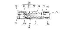
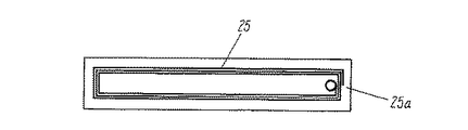
図6はこの種の従来のスリム型のスピーカの構成を示した断面図、図7は同スピーカに使用されるボイスコイルを示した平面図であり、本出願人がスリム型のスピーカとして提案したものである。 FIG. 6 is a cross-sectional view showing the configuration of a conventional slim speaker of this type, and FIG. 7 is a plan view showing a voice coil used in the speaker, which the applicant has proposed as a slim speaker. Is.
図6、図7において、20は第1のマグネット、21はこの第1のマグネット20を中心に結合した第1のヨークであり、これにより第1の磁気ギャップ20aを設けた第1の磁気回路22が構成されている。23は上記第1のヨーク21を中心に結合した第1のフレーム、23aはこの第1のフレーム23に設けられた空気孔である。24は振動板、24aはこの振動板24に設けられたエッジであり、この振動板24の周縁は上記第1のフレーム23の周縁に結合されている。25は上記振動板24に結合されたボイスコイルであり、このボイスコイル25は上記第1の磁気ギャップ20aと対応する形状に複数ターン巻回されたものである。
6 and 7,
26は上記振動板24を挟むようにして第1の磁気回路22と対称に配設された第2の磁気回路であり、第1の磁気回路22と同様に、第2のヨーク27の中心に第2のマグネット28を結合することにより第2の磁気ギャップ28aを設け、この第2の磁気回路26を第2のフレーム29の中心に結合して構成されているものである。29aは第2のフレーム29に設けられた空気孔である。
25aは上記ボイスコイル25の始終端に夫々接続された外部引き出し用のリード線であり、このリード線25aの一端を第1(または第2)のフレーム23に結合された図示しない端子に半田付けによって接続するように構成されているものである。
このように構成された従来のスピーカは、上記第1のマグネット20と第2のマグネット28は厚み方向に、かつ夫々が反発する方向に着磁され、第1の磁気ギャップ20aと第2の磁気ギャップ28aから夫々発生する漏れ磁界を最大に活用できる位置にボイスコイル25を配置することにより、ボイスコイル25に音声信号を入力することによってボイスコイル25が上下に振幅し、これによってボイスコイル25を結合した振動板24が振幅して音響再生を行うように構成されたものであった。
In the conventional speaker configured as described above, the
なお、この出願の発明に関連する先行技術文献情報としては、例えば、特許文献1が知られている。
しかしながら上記従来のスピーカでは、第1(または第2)の磁気回路22ならびにボイスコイル25の形状が矩形(楕円形、長円形、トラック形のいずれかであっても同じ)であるために、振動板24も必然的に同様の形状に形成されており、この結果、振動板24の長手方向の中央部では両端部に比べて弾性が小さくなるという固有の問題を有していた。
However, in the above conventional speaker, the first (or second)
このために、ボイスコイル25に音声信号を入力して第1(または第2)の磁気ギャップ20aから発生する磁界により振動板24を振幅させて音響再生を行う際に、振動板24全体が均一なストロークで振幅するのではなく、両端部に比べて弾性が小さい長手方向の中央部のみが必要以上に振幅する(一般に太鼓運動と呼ばれている)という現象が発生するようになるために特性を悪化させるばかりでなく、所定の入力を印加することができないために高耐入力化が図れないという致命的な課題を有したものであった。
Therefore, when the sound signal is input to the
本発明はこのような従来の課題を解決し、矩形等の形状の振動板を用いた場合でも振動板全体が均一に振幅し、優れた性能と高耐入力化を実現することが可能なスピーカを提供することを目的とするものである。 The present invention solves such a conventional problem, and even when a diaphragm having a rectangular shape or the like is used, the entire diaphragm has a uniform amplitude and can realize excellent performance and high input resistance. Is intended to provide.
上記課題を解決するために本発明は、マグネットとヨークを結合することにより構成された磁気ギャップを有する磁気回路と、この磁気回路を結合したフレームと、上記磁気ギャップの上部に磁気ギャップと非接触状態で近接配置されたボイスコイルと、このボイスコイルを結合し、外周部が上記フレームに結合された振動板からなり、上記振動板ならびにボイスコイル、磁気ギャップの形状が矩形、楕円形、長円形、トラック形のいずれかからなるスピーカにおいて、上記ボイスコイルは、樹脂フィルム上に銅めっきにより複数ターンのコイルを巻回形成すると共に、この巻回されたコイルの内部にコイルとは電気的に接続されないダミーコイルを、巻回されたコイルの内部の長手方向の中心に設けるか、または巻回されたコイルの内部の長手方向の中心を基準にし、長手方向に対称に複数個設けた構成とすることで、振動板の長手方向の中央部の弾性を振動板の長手方向の両端部に比べて大きくして振動板全体を均一に振幅させ、優れた性能と高耐入力化を同時に実現したものである。 In order to solve the above problems, the present invention provides a magnetic circuit having a magnetic gap formed by coupling a magnet and a yoke, a frame in which the magnetic circuit is coupled, and a magnetic gap above the magnetic gap in a noncontact manner. A voice coil that is closely arranged in a state and a diaphragm in which the voice coil is coupled and an outer peripheral portion is coupled to the frame. The shape of the diaphragm, the voice coil, and the magnetic gap are rectangular, elliptical, and oval. In a speaker having a track shape, the voice coil is formed by winding a coil of multiple turns on a resin film by copper plating and electrically connected to the coil inside the wound coil. the dummy coil is not, or provided within the longitudinal center of the wound coil, or wound inside the coil The center of the longitudinal direction on the basis, with a configuration provided plurality symmetrically longitudinally vibration of the elastic in the longitudinal direction of the central portion of the diaphragm is increased in comparison with the both ends in the longitudinal direction of the diaphragm plate The entire system is uniformly oscillated to achieve excellent performance and high input resistance at the same time .
以上のように本発明によるスピーカは、ボイスコイルのコイルの内部に、コイルとは電気的に接続されないダミーコイルを設けたことにより、このダミーコイルによって剛性が上がるため、結果としてこのボイスコイルを結合した振動板の弾性が大きくなり、従来のように矩形等の形状の振動板の長手方向の中央部では両端部に比べて弾性が小さくなるという固有の問題を解消して振動板全体が均一に振幅し、これにより優れた性能と高耐入力化を同時に実現することができるという格別の効果が得られるものである。 As described above, the speaker according to the present invention is provided with a dummy coil that is not electrically connected to the coil inside the coil of the voice coil, so that the rigidity is increased by this dummy coil. The elasticity of the diaphragm is increased, and the inherent problem that the elasticity is smaller at the central part in the longitudinal direction of the rectangular-shaped diaphragm as compared with the both ends is eliminated and the entire diaphragm is made uniform. As a result, it is possible to obtain an exceptional effect that excellent performance and high input resistance can be realized at the same time.
(実施の形態1)
以下、実施の形態1を用いて、本発明について説明する。
(Embodiment 1)
Hereinafter, with reference to the first embodiment will be described with the present onset bright.
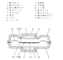
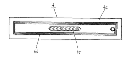
図1は本発明の実施の形態1によるスピーカの構成を示した断面図、図2は同スピーカに使用されるボイスコイルを示した平面図であり、図1、図2において、1は磁性金属材料からなる矩形状の第1のヨーク、2は矩形状の第1のマグネットであり、この第1のマグネット2を上記第1のヨーク1内に嵌め込んで結合することにより第1の磁気回路を構成すると共に、第1のヨーク1の内壁面と第1のマグネット2の外周面との間に矩形状の均等な隙間を設けた第1の磁気ギャップ2aが形成されている。
FIG. 1 is a cross-sectional view showing a configuration of a speaker according to
3は上記第1の磁気回路を構成する第1のヨーク1を中心に結合した第1のフレームであり、樹脂または金属材料等で形成されているものである。
4はボイスコイルであり、このボイスコイル4はポリイミド製の基材4aの表面(本実施の形態においては裏面にも同様に形成されている)に銅めっきにより所望のパターンのコイル4bが矩形状に巻回状態で形成され、この矩形状に巻回されたコイル4bは上記第1の磁気回路に設けられた第1の磁気ギャップ2aと略同形状に形成されているものである。4cは上記コイル4bの内部のコイルが形成されていない部分に形成されたダミーコイルであり、このダミーコイル4cは上記コイル4bとは電気的に接続されておらず、かつ長手方向の略中央にコイル4bと同様に銅めっきにより形成されたものである。
5は樹脂からなる矩形状の振動板であり、この振動板5は、中央部に平板状の本体部5aと、この本体部5aの周縁にエッジ部5bと、このエッジ部5bの周縁に平板状の貼り付け部が一体構造で形成されているものである。
6は磁性金属材料からなる矩形状の第2のヨーク、7は矩形状の第2のマグネットであり、この第2のマグネット7を上記第2のヨーク6内に嵌め込んで結合することにより第2の磁気回路を構成すると共に、第2のヨーク6の内壁面と第2のマグネット7の外周面との間に矩形状の均等な隙間を設けた第2の磁気ギャップ7aが形成されている。
Reference numeral 6 denotes a rectangular second yoke made of a magnetic metal material, and
8は上記第2の磁気回路を構成する第2のヨーク6を中心に結合した第2のフレームであり、樹脂または金属材料等で形成され、この第2のフレーム8ならびに第2の磁気回路は上記振動板5を介して対向して配設されることにより、振動板5の周縁の貼り付け部を第1のフレーム3の周縁と第2のフレーム8の周縁で挟み込むように結合すると共に、振動板5に結合されたボイスコイル4が第1の磁気ギャップ2aと第2の磁気ギャップ7aの略中間位置に配設されるように構成されたものである。
Reference numeral 8 denotes a second frame coupled around the second yoke 6 constituting the second magnetic circuit, which is formed of a resin or a metal material. The second frame 8 and the second magnetic circuit are By being disposed so as to face each other through the
このように構成された本実施の形態によるスピーカは、ボイスコイル4のコイル4bの内部に、コイル4bとは電気的に接続されないダミーコイル4cを設けたことにより、このダミーコイル4cによって剛性が上がるため、結果としてこのボイスコイル4を結合した振動板5の弾性が大きくなり、従来のように矩形等の形状の振動板5の長手方向の中央部では両端部に比べて弾性が小さくなるという固有の問題を解消して振動板5全体が均一に振幅し、これにより優れた性能と高耐入力化を同時に実現することができるという格別の効果が得られるものである。
The speaker according to the present embodiment configured as described above is provided with a
(実施の形態2)
以下、実施の形態2を用いて、本発明について説明する。
(Embodiment 2)
Hereinafter, with reference to the second embodiment will be described with the present onset bright.
本実施の形態は、上記実施の形態1によるスピーカに使用されたボイスコイルの構成が一部異なるようにしたものであり、これ以外の構成は実施の形態1と同様であるために同一部分には同一の符号を付与してその詳細な説明は省略し、異なる部分についてのみ以下に図面を用いて説明する。 In the present embodiment, the configuration of the voice coil used in the speaker according to the first embodiment is partially different, and the other configuration is the same as that of the first embodiment, and therefore the same portion. Are given the same reference numerals and detailed description thereof is omitted, and only different parts will be described below with reference to the drawings.
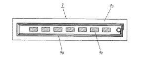
図3は本発明の実施の形態2によるスピーカに使用されるボイスコイルの構成を示した平面図であり、図3において9はボイスコイルであり、このボイスコイル9はポリイミド製の基材9aの表面(本実施の形態においては裏面にも同様に形成されている)に銅めっきにより所望のパターンのコイル9bが矩形状に巻回状態で形成され、この矩形状に巻回されたコイル9bは上記第1の磁気回路に設けられた第1の磁気ギャップ2aと略同形状に形成されているものである。
FIG. 3 is a plan view showing the configuration of a voice coil used in the speaker according to the second embodiment of the present invention. In FIG. 3, 9 is a voice coil, and this
9cは上記コイル9bの内部のコイルが形成されていない部分に形成されたダミーコイルであり、このダミーコイル9cは上記コイル9bとは電気的に接続されておらず、かつ長手方向の中心を基準にし、長手方向に対称に複数個がコイル9bと同様に銅めっきにより形成されたものである。 9c is a dummy coil formed in a portion of the coil 9b where the coil is not formed. The dummy coil 9c is not electrically connected to the coil 9b and is based on the center in the longitudinal direction. In the same manner as the coil 9b, a plurality of pieces are formed by copper plating symmetrically in the longitudinal direction.
このように構成された本実施の形態によるスピーカは、ボイスコイル9にダミーコイル9cを設けた構成により上記実施の形態1によるスピーカと同様の効果が得られることに加え、矩形状の振動板5の弾性特性に応じてダミーコイル9cを設定することにより、このボイスコイル9を結合した振動板5の弾性特性を最適なものに調整することができるという格別の効果が得られるものである。
The speaker according to the present embodiment configured as described above has the same effect as the speaker according to the first embodiment by the configuration in which the dummy coil 9c is provided in the
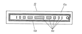
また、図4は本実施の形態によるスピーカに使用されるボイスコイルの他の例を示したボイスコイルの平面図であり、上記図3で示したボイスコイル9と同様に、ポリイミド製の基材10aの表面に銅めっきによりコイル10bが矩形状に巻回状態で形成されると共に、複数個のダミーコイル10cが形成されたものであり、このダミーコイル10cは夫々大きさが異なるように構成されたものである。
FIG. 4 is a plan view of a voice coil showing another example of the voice coil used in the speaker according to the present embodiment. Like the
なお、このように構成されたボイスコイル10の効果は上記図3で示したボイスコイル9と同様であるために、ここでの説明は省略する。
Since the effect of the
(実施の形態3)
以下、実施の形態3を用いて、本発明について説明する。
(Embodiment 3)
Hereinafter, with reference to the third embodiment will be described with the present onset bright.
図5(a)〜(c)は本発明の実施の形態3によるスピーカに使用される振動板の構成を示した平面図と、A−A線における断面図とB−B線における断面図であり、同図において11は樹脂からなる矩形状の振動板であり、この振動板11は中央部に平板状の本体部11aと、この本体部11aの周縁にエッジ部11bと、このエッジ部11bの周縁に平板状の貼り付け部11cが一体構造で形成されると共に、上記エッジ部11bの長手方向の中央部には複数のリブ11dが設けられた構成のものである。
5A to 5C are a plan view showing a configuration of a diaphragm used in the speaker according to
このように構成された本実施の形態によるスピーカは、振動板11のエッジ部11bの長手方向に複数のリブ11dを設けた構成によって振動板11の剛性が上がるため、従来のように矩形等の形状の振動板11の長手方向の中央部では両端部に比べて弾性が小さくなるという固有の問題を解消して振動板11が全体に均一に振幅し、これにより優れた性能と高耐入力化を同時に実現することができるという格別の効果が得られるものである。
In the speaker according to the present embodiment configured as described above, the rigidity of the diaphragm 11 is increased by the configuration in which the plurality of
本発明によるスピーカは、矩形等の形状の振動板を用いた場合でも振動板全体が均一に振幅し、優れた性能と高耐入力化を実現することができるという特徴を有し、各種音響機器、電子機器、あるいは携帯電話用等として有用である。 The speaker according to the present invention has a feature that even when a diaphragm having a rectangular shape or the like is used, the entire diaphragm has a uniform amplitude and can realize excellent performance and high input resistance. It is useful for electronic devices or mobile phones.
1 第1のヨーク
2 第1のマグネット
2a 第1の磁気ギャップ
3 第1のフレーム
4、9、10 ボイスコイル
4a、9a、10a 基材
4b、9b、10b コイル
4c、9c、10c ダミーコイル
5、11 振動板
5a、11a 本体部
5b、11b エッジ部
6 第2のヨーク
7 第2のマグネット
7a 第2の磁気ギャップ
8 第2のフレーム
11c 貼り付け部
11d リブ
DESCRIPTION OF
Claims (2)
Priority Applications (1)
| Application Number | Priority Date | Filing Date | Title |
|---|---|---|---|
| JP2004287027A JP4591017B2 (en) | 2004-09-30 | 2004-09-30 | Speaker |
Applications Claiming Priority (1)
| Application Number | Priority Date | Filing Date | Title |
|---|---|---|---|
| JP2004287027A JP4591017B2 (en) | 2004-09-30 | 2004-09-30 | Speaker |
Publications (2)
| Publication Number | Publication Date |
|---|---|
| JP2006101367A JP2006101367A (en) | 2006-04-13 |
| JP4591017B2 true JP4591017B2 (en) | 2010-12-01 |
Family
ID=36240733
Family Applications (1)
| Application Number | Title | Priority Date | Filing Date |
|---|---|---|---|
| JP2004287027A Expired - Fee Related JP4591017B2 (en) | 2004-09-30 | 2004-09-30 | Speaker |
Country Status (1)
| Country | Link |
|---|---|
| JP (1) | JP4591017B2 (en) |
Families Citing this family (4)
| Publication number | Priority date | Publication date | Assignee | Title |
|---|---|---|---|---|
| JP5413966B2 (en) * | 2009-11-09 | 2014-02-12 | アルパイン株式会社 | Speaker device |
| KR101420320B1 (en) | 2013-03-26 | 2014-07-17 | 신 렬 이 | Ultra Slim diaphragm driving Speaker |
| TW201813417A (en) * | 2016-09-20 | 2018-04-01 | 固昌通訊股份有限公司 | Planar speaker unit |
| CN111935614B (en) * | 2020-10-13 | 2021-01-22 | 歌尔股份有限公司 | Loudspeaker |
Citations (5)
| Publication number | Priority date | Publication date | Assignee | Title |
|---|---|---|---|---|
| JPS5122433U (en) * | 1974-08-09 | 1976-02-19 | ||
| JPS5345228A (en) * | 1976-10-05 | 1978-04-22 | Sanyo Electric Co Ltd | Preparation of vibrating plate for speaker |
| JPS5634297A (en) * | 1979-08-29 | 1981-04-06 | Kenzo Inoue | Speaker unit |
| JPS5757697U (en) * | 1980-09-22 | 1982-04-05 | ||
| JP2004088739A (en) * | 2002-06-24 | 2004-03-18 | Matsushita Electric Ind Co Ltd | Speaker diaphragm |
-
2004
- 2004-09-30 JP JP2004287027A patent/JP4591017B2/en not_active Expired - Fee Related
Patent Citations (5)
| Publication number | Priority date | Publication date | Assignee | Title |
|---|---|---|---|---|
| JPS5122433U (en) * | 1974-08-09 | 1976-02-19 | ||
| JPS5345228A (en) * | 1976-10-05 | 1978-04-22 | Sanyo Electric Co Ltd | Preparation of vibrating plate for speaker |
| JPS5634297A (en) * | 1979-08-29 | 1981-04-06 | Kenzo Inoue | Speaker unit |
| JPS5757697U (en) * | 1980-09-22 | 1982-04-05 | ||
| JP2004088739A (en) * | 2002-06-24 | 2004-03-18 | Matsushita Electric Ind Co Ltd | Speaker diaphragm |
Also Published As
| Publication number | Publication date |
|---|---|
| JP2006101367A (en) | 2006-04-13 |
Similar Documents
| Publication | Publication Date | Title |
|---|---|---|
| US10299045B2 (en) | Miniature speaker | |
| KR101042032B1 (en) | Micro-speaker | |
| US20050220320A1 (en) | Speaker for mobile terminals and manufacturing method thereof | |
| US10750286B2 (en) | Speaker | |
| US8615102B2 (en) | Speaker unit and portable information terminal | |
| JP2008312056A (en) | Electroacoustic transducer | |
| US20190208325A1 (en) | Miniature Speaker | |
| JP3844074B2 (en) | Diaphragm for flat coil speaker and flat coil speaker using the same | |
| JP3815740B2 (en) | Fully driven flat speaker | |
| KR101184537B1 (en) | Speaker | |
| US20120308070A1 (en) | Slim type speaker and magnetic circuit therefor | |
| JP4591017B2 (en) | Speaker | |
| JP6667364B2 (en) | Flat speaker and method for improving its frequency characteristics | |
| JP4305228B2 (en) | Slim speaker and module, electronic device and apparatus using the same | |
| JP4403941B2 (en) | Speaker | |
| CN112449288B (en) | Flexible circuit board, speaker and electronic equipment | |
| JP4475085B2 (en) | Speaker | |
| CN110572751B (en) | Speaker assembly, assembling method of speaker assembly, and sound generating apparatus | |
| KR200284571Y1 (en) | Unilateral/Bilateral Electric-Sound Converter Having Fixed Coil Structure Using Magnetization Film | |
| KR100937335B1 (en) | Micro speaker and method for fabricating the same | |
| JP4591018B2 (en) | Speaker | |
| KR100401000B1 (en) | Speaker United in Receiver | |
| KR100570857B1 (en) | Diaphragm for micro speak and micro speak having thereof | |
| KR20030083774A (en) | Unilateral/Bilateral Electric-Sound Converter Having Fixed Coil Structure Using Magnetization Film and Method Thereof | |
| JP2006109123A (en) | Speaker and manufacturing method thereof |
Legal Events
| Date | Code | Title | Description |
|---|---|---|---|
| A621 | Written request for application examination |
Free format text: JAPANESE INTERMEDIATE CODE: A621 Effective date: 20070406 |
|
| RD01 | Notification of change of attorney |
Free format text: JAPANESE INTERMEDIATE CODE: A7421 Effective date: 20070514 |
|
| A977 | Report on retrieval |
Free format text: JAPANESE INTERMEDIATE CODE: A971007 Effective date: 20090821 |
|
| A131 | Notification of reasons for refusal |
Free format text: JAPANESE INTERMEDIATE CODE: A131 Effective date: 20090908 |
|
| A521 | Written amendment |
Free format text: JAPANESE INTERMEDIATE CODE: A523 Effective date: 20091109 |
|
| RD01 | Notification of change of attorney |
Free format text: JAPANESE INTERMEDIATE CODE: A7421 Effective date: 20091120 |
|
| TRDD | Decision of grant or rejection written | ||
| A01 | Written decision to grant a patent or to grant a registration (utility model) |
Free format text: JAPANESE INTERMEDIATE CODE: A01 Effective date: 20100817 |
|
| A01 | Written decision to grant a patent or to grant a registration (utility model) |
Free format text: JAPANESE INTERMEDIATE CODE: A01 |
|
| A61 | First payment of annual fees (during grant procedure) |
Free format text: JAPANESE INTERMEDIATE CODE: A61 Effective date: 20100830 |
|
| FPAY | Renewal fee payment (event date is renewal date of database) |
Free format text: PAYMENT UNTIL: 20130924 Year of fee payment: 3 |
|
| FPAY | Renewal fee payment (event date is renewal date of database) |
Free format text: PAYMENT UNTIL: 20130924 Year of fee payment: 3 |
|
| LAPS | Cancellation because of no payment of annual fees |