JP4579613B2 - Image processing apparatus and method, and imaging apparatus - Google Patents
Image processing apparatus and method, and imaging apparatus Download PDFInfo
- Publication number
- JP4579613B2 JP4579613B2 JP2004228014A JP2004228014A JP4579613B2 JP 4579613 B2 JP4579613 B2 JP 4579613B2 JP 2004228014 A JP2004228014 A JP 2004228014A JP 2004228014 A JP2004228014 A JP 2004228014A JP 4579613 B2 JP4579613 B2 JP 4579613B2
- Authority
- JP
- Japan
- Prior art keywords
- image data
- image
- memory
- pixels
- unit
- Prior art date
- Legal status (The legal status is an assumption and is not a legal conclusion. Google has not performed a legal analysis and makes no representation as to the accuracy of the status listed.)
- Expired - Fee Related
Links
Images


Classifications
-
- G—PHYSICS
- G06—COMPUTING; CALCULATING OR COUNTING
- G06V—IMAGE OR VIDEO RECOGNITION OR UNDERSTANDING
- G06V10/00—Arrangements for image or video recognition or understanding
- G06V10/20—Image preprocessing
- G06V10/24—Aligning, centring, orientation detection or correction of the image
- G06V10/242—Aligning, centring, orientation detection or correction of the image by image rotation, e.g. by 90 degrees
Landscapes
- Engineering & Computer Science (AREA)
- Physics & Mathematics (AREA)
- General Physics & Mathematics (AREA)
- Multimedia (AREA)
- Theoretical Computer Science (AREA)
- Studio Devices (AREA)
- Editing Of Facsimile Originals (AREA)
Description
本発明は、画像処理装置及び方法、及び撮像装置に関し、特に詳しくは、撮像装置により撮像された画像に対して、撮像装置の姿勢に応じた処理を行う画像処理装置及び方法、及び撮像装置に関する。 The present invention relates to an image processing apparatus and method, and an imaging apparatus, and more particularly to an image processing apparatus and method for performing processing according to the attitude of the imaging apparatus on an image captured by the imaging apparatus, and the imaging apparatus. .
従来、デジタルカメラなどの撮像装置により撮影された画像の処理を行う画像処理装置は、撮影された画像の画像データを圧縮後、または圧縮せずにそのまま記録部へ記録し、また、再生時には記録部から画像データを読み出し、圧縮データであれば伸張した後、また、圧縮していなければそのまま、撮影時のカメラの姿勢に何ら関係なく、モニタの表示画面に表示していた。 Conventionally, an image processing apparatus that processes an image captured by an imaging device such as a digital camera records the image data of the captured image as it is in a recording unit after compression or without compression, and also records it during reproduction. After the image data is read out from the scanning unit, if it is compressed data, it is decompressed, and if it is not compressed, it is displayed on the display screen of the monitor as it is regardless of the posture of the camera at the time of photographing.
図10は撮影時のカメラの姿勢と、表示される画像との関係を表したものである。図10(a)は撮影時にカメラのファインダーから覗いた撮影領域の観察画像であり、ここでは撮影領域が横長になるようなカメラの姿勢(横位置)で撮影する時の様子を示している。図10(b)は、図10(a)に示すように横位置で撮影した時に撮像素子から出力される画像データの概念を示す図であり、この画像を、例えばTV等の表示装置へ表示した時の様子が図10(c)である。この場合、表示された画像の上下方向が、撮影時にファインダーから覗いた観察画像の上下方向と同じであることが判る。 FIG. 10 shows the relationship between the posture of the camera at the time of shooting and the displayed image. FIG. 10A is an observation image of a shooting area viewed from the camera finder at the time of shooting, and shows a state when shooting is performed with the camera posture (horizontal position) such that the shooting area is horizontally long . FIG. 10B is a diagram showing the concept of the image data output from the image sensor when imaged in the horizontal position as shown in FIG. 10A, and this image is displayed on a display device such as a TV, for example. FIG. 10 (c) shows the state when this is done. In this case, the vertical direction of the displayed image, it can be seen that the same as the vertical direction of the observation image had Prying the viewfinder during shooting.
また、図11は図10と同様に、撮影時のカメラの姿勢と、表示される画像の関係を表したものである。図11(a)は撮影時にカメラのファインダーから覗いた撮影領域の観察画像であり、ここでは撮影領域が縦長になるようなカメラの姿勢(縦位置)で撮影する時の様子を示している。この例では、カメラを右方向に90°回転させた状態である。図11(b)は、図11(a)に示すように縦位置で撮影した時に撮像素子から出力される画像データの概念を示す図であり、この画像を、例えばTV等の表示装置へ表示した時の様子が図11(c)である。この場合、撮影時に撮影者がカメラのファインダーから覗いた観察画像の上下方向に対して、90°回転した表示となっている。 FIG. 11 shows the relationship between the posture of the camera at the time of shooting and the displayed image, as in FIG. FIG. 11A is an observation image of a shooting area viewed from the camera finder at the time of shooting, and shows a situation when shooting is performed with the camera posture (vertical position) such that the shooting area is vertically long. In this example, the camera is rotated 90 degrees rightward. FIG. 11B is a diagram showing the concept of the image data output from the image sensor when the image is taken in the vertical position as shown in FIG. 11A, and this image is displayed on a display device such as a TV, for example. FIG. 11 (c) shows the state when this is done. In this case, the display is rotated by 90 ° with respect to the vertical direction of the observation image viewed from the viewfinder of the camera at the time of shooting.
図10(c)と図11(c)を比較すると、横位置で撮影した場合の図10(c)は、表示された画像の上下方向が正しいのでこのまま違和感なく鑑賞することができるが、縦位置で撮影した場合の図11(c)では、画像が左方向に90°回転し上下方向が違っているので、このままでは鑑賞しにくい。 Comparing FIG. 10 (c) and FIG. 11 (c), FIG. 10 (c) when taken in the horizontal position can be viewed without any sense of incongruity because the vertical direction of the displayed image is correct. In FIG. 11C in which the image is taken at the position, the image is rotated 90 ° to the left and the vertical direction is different.
これに対し、特許文献1では、カメラの姿勢検出センサで撮影時のカメラの姿勢を検出し、検出されたカメラの姿勢に応じてフレームメモリに格納された画像データの読み出す順序を変えることで、撮影時の観察画像の上下方向と、表示時の画像の上下方向が同じになるような画像を表す圧縮画像データを生成することが提案されている。
On the other hand, in
また、特許文献2では、カメラの撮像領域における長手方向が縦位置か横位置かを検出するカメラ位置検出部と、縦位置用と横位置用の2種類の量子化テーブルを設け、量子化テーブル選択部はカメラ位置に従って量子化テーブルを選択し、量子化処理回路に出力する。そしてDCT処理回路から出力されたDCT係数を、量子化処理回路において選択された量子化テーブルを用いて量子化することが提案されている。
In
しかしながら、例えば画像データに付加されている撮影時の姿勢情報に従って、縦位置で撮影した画像を違和感なく鑑賞できるように、表示の際に右方向へ90°あるいは270°(つまり、左方向へ90°)の回転処理を行う場合、回転処理に時間がかかる。この回転処理に係る時間は、画像情報すなわち画素数が多くなればさらに増大するため、再生表示のためのスイッチ操作部材を操作してから表示されるまでの待ち時間が増大することになる。 However, for example, according to the posture information added to the image data, 90 ° or 270 ° to the right (that is, 90 ° to the left) is displayed so that an image shot in the vertical position can be viewed without a sense of incongruity. When the rotation process (°) is performed, the rotation process takes time. The time related to the rotation processing increases further as the image information, that is, the number of pixels increases, so that the waiting time from when the switch operation member for reproduction display is operated until display is increased.
本発明は上記問題点を鑑みてなされたものであり、回転処理の一時記憶メモリ(ワークレジスタ)を削減し、縦位置で撮影した画像の回転処理にかかる時間を短縮し、横位置で撮影した画像と同等の再生処理時間で、表示装置に縦位置で再生表示できるようにすることを目的とする。 The present invention has been made in view of the above-described problems. The temporary storage memory (work register) for rotation processing is reduced, the time required for rotation processing of an image shot in the vertical position is shortened, and the image is shot in the horizontal position. It is an object of the present invention to enable reproduction and display on a display device in a vertical position with a reproduction processing time equivalent to that of an image.
上記目的を達成するために、複数の光電変換素子が2次元に配設され、入射光量に応じて電気信号を出力する撮像素子を有する撮像装置により撮像された画像データを処理する本発明の画像処理装置は、前記撮像装置から出力される画像データを1フレーム分記憶するメモリと、前記画像データが撮像されたときの前記撮像装置の姿勢情報を検出する姿勢情報検出手段と、前記姿勢情報検出手段により検出された前記姿勢情報が縦位置である場合に、前記メモリに記憶された画像データを、横i個、縦j個のi×j個に分割された領域それぞれを構成する所定画素数単位ずつ、第1の方向に順に読み出し、読み出した前記所定画素数単位毎の画像データに順次回転処理を行う回転手段と、前記姿勢情報が縦位置である場合には前記回転手段により処理された画像データを、前記姿勢情報が横位置である場合には前記メモリに記憶された画像データを前記第1の方向と前記姿勢情報とに基づいた第2の方向に前記所定画素数単位ずつ順に読み出された画像データを、各領域が前記所定画素数単位であるi×j個の領域に、前記第2の方向に順次記憶する記憶手段と、前記姿勢情報が縦位置である場合に、前記回転手段により処理され、前記記憶手段に記憶された画像データを縦位置で表示させるための姿勢情報を、前記画像データと共に前記記憶手段に記憶させる姿勢情報付加手段とを有する。 In order to achieve the above object, an image of the present invention that processes image data picked up by an image pickup device having a plurality of photoelectric conversion elements arranged two-dimensionally and having an image pickup element that outputs an electrical signal according to the amount of incident light The processing device includes a memory for storing one frame of image data output from the imaging device, posture information detection means for detecting posture information of the imaging device when the image data is imaged, and posture information detection When the posture information detected by the means is a vertical position, the predetermined number of pixels constituting each of the areas obtained by dividing the image data stored in the memory into i × j i × j regions Rotating means that sequentially reads out unit by unit in the first direction and sequentially performs rotation processing on the read image data in units of the predetermined number of pixels. When the posture information is a vertical position, the rotating means Ri the processed image data, wherein the predetermined number of pixels in the second direction based on the image data stored in said memory to said orientation information and the first direction when the position information is horizontal position the image data that has been read out one by the unit, the i × j number of regions each region is the predetermined number of pixels units, storage means for sequentially storing in the second direction, wherein the orientation information is in the vertical position In this case, there is provided posture information adding means for storing posture information for displaying the image data processed by the rotating means and stored in the storage means in a vertical position in the storage means together with the image data.
また、複数の光電変換素子が2次元に配設され、入射光量に応じて画像データを出力する撮像素子により画像を撮像する本発明の撮像装置は、前記撮像素子から出力される画像データを1フレーム分記憶するメモリと、前記画像データが撮像されたときの前記撮像装置の姿勢を検出する姿勢検出手段と、前記姿勢検出手段により検出された前記姿勢が縦位置である場合に、前記メモリに記憶された画像データを、横i個、縦j個のi×j個に分割された領域それぞれを構成する所定画素数単位ずつ、第1の方向に順に読み出し、読み出した前記所定画素数単位毎の画像データに順次回転処理を行う回転手段と、前記姿勢情報が縦位置である場合には前記回転手段により処理された画像データを、前記姿勢情報が横位置である場合には前記メモリに記憶された画像データを前記第1の方向と前記姿勢情報とに基づいた第2の方向に前記所定画素数単位ずつ順に読み出された画像データを、各領域が前記所定画素数単位であるi×j個の領域に、前記第2の方向に順次記憶する記憶手段と、前記姿勢情報が縦位置である場合に、前記回転手段により処理され、前記記憶手段に記憶された画像データを縦位置で表示させるための姿勢情報を、前記画像データと共に前記記憶手段に記憶させる姿勢情報付加手段とを有する。 In addition, an image pickup apparatus according to the present invention in which a plurality of photoelectric conversion elements are arranged two-dimensionally and picks up an image with an image pickup element that outputs image data according to the amount of incident light. Memory for storing frames, posture detection means for detecting the posture of the imaging device when the image data is picked up, and when the posture detected by the posture detection means is a vertical position in the memory The stored image data is sequentially read in the first direction in units of a predetermined number of pixels that constitute each of the i × j regions divided into i in the horizontal direction and j in the vertical direction. Rotating means for sequentially rotating the image data, image data processed by the rotating means when the posture information is a vertical position, and the memo when the posture information is a horizontal position. Reading out image data one by the predetermined number of pixels units in the second direction, each region is the predetermined number of pixels units based image data stored in the and the posture information to the first direction Storage means for sequentially storing the i × j areas in the second direction and image data processed by the rotation means and stored in the storage means when the posture information is a vertical position. Posture information adding means for storing posture information for displaying at a position in the storage means together with the image data.
また、複数の光電変換素子が2次元に配設され、入射光量に応じて電気信号を出力する撮像素子を有する撮像装置により撮像された画像データを処理する本発明の画像処理方法は、前記撮像装置から出力される画像データをメモリに1フレーム分記憶する第1の記憶工程と、前記画像データが撮像されたときの前記撮像装置の姿勢情報を検出する姿勢情報検出工程と、前記姿勢情報検出工程で検出された前記姿勢情報が縦位置である場合に、前記メモリに記憶された画像データを、横i個、縦j個のi×j個に分割された領域それぞれを構成する所定画素数単位ずつ、第1の方向に順に読み出し、読み出した前記所定画素数単位毎の画像データに順次回転処理を行う回転工程と、前記姿勢情報が縦位置である場合には前記回転工程で処理された画像データを、前記姿勢情報が横位置である場合には前記メモリに記憶された画像データを前記第1の方向と前記姿勢情報とに基づいた第2の方向に前記所定画素数単位ずつ順に読み出された画像データを、各領域が前記所定画素数単位であるi×j個の領域に、前記第2の方向に順次記憶手段に記憶する第2の記憶工程と、前記姿勢情報が縦位置である場合に、前記回転工程で処理され、前記記憶手段に記憶された画像データを縦位置で表示させるための姿勢情報を、前記画像データと共に前記記憶手段に記憶させる姿勢情報付加工程とを有する。 In addition, the image processing method of the present invention for processing image data captured by an imaging device having an imaging device in which a plurality of photoelectric conversion elements are two-dimensionally arranged and outputs an electrical signal according to the amount of incident light includes the imaging A first storage step of storing image data output from the device for one frame in a memory; a posture information detection step of detecting posture information of the imaging device when the image data is captured; and the posture information detection When the posture information detected in the process is the vertical position, the predetermined number of pixels constituting each of the areas obtained by dividing the image data stored in the memory into i × j and i × j regions A rotation process that sequentially reads out unit by unit in the first direction and sequentially rotates the read image data for each unit of the predetermined number of pixels. If the posture information is a vertical position, the rotation process performs the rotation process. Image data, the posture information in the case of a horizontal position to read one by the predetermined number of pixels units in the second direction based on the image data stored in said memory to said orientation information and the first direction the output image data, the i × j number of regions each region is the predetermined number of pixels units, and a second storage step of storing sequentially storing means in the second direction, wherein the orientation information is the vertical position A posture information adding step of storing posture information for displaying the image data processed in the rotation step and stored in the storage unit in a vertical position in the storage unit together with the image data. .
本発明によれば、回転処理のためのワークレジスタを削減して効率的な回転処理を行うと共に、縦位置で撮影した画像の回転処理にかかる時間を短縮し、横位置で撮影した画像と同等の再生処理時間で、表示装置に縦位置で再生表示できるようにすることができる。 According to the present invention, efficient rotation processing is performed by reducing the work register for rotation processing, and the time required for rotation processing of an image shot in the vertical position is shortened, which is equivalent to an image shot in the horizontal position. It is possible to reproduce and display the image on the display device in the vertical position within the reproduction processing time.
以下、添付図面を参照して本発明を実施するための最良の形態を詳細に説明する。 The best mode for carrying out the present invention will be described below in detail with reference to the accompanying drawings.
<第1の実施形態>
本発明の第1の実施形態について説明する。
<First Embodiment>
A first embodiment of the present invention will be described.
図1は、本発明の第1の実施形態であるデジタルカメラ等の撮像装置の概略構成を示すブロック図である。 FIG. 1 is a block diagram showing a schematic configuration of an imaging apparatus such as a digital camera according to the first embodiment of the present invention.
図1において、13はCCDエリアセンサ等からなる撮像部、141は撮像部13からの画像信号を処理する原画処理部、142は第1メモリ、7は回転処理部、10は符号化部、143は第2メモリ、9は複数の画像データを保存する容量を有する不揮発性の記憶部材からなる記憶部、8は画像処理装置の姿勢を検出する姿勢検出部、140は画像処理全体の制御を行うマイコン(PRS)、144は表示メモリ、6はLCDなどの表示部である。また、スイッチ101、102、103、104を有し、後述するように画像データの入出力を切り換える。PRS140は、たとえば、内部にCPU(中央演算処理部)、RAM、ROM、EEPROM(電気的消去可能プログラマブルROM)、入出力ポ−ト等が配置された、ワンチップのコンピュ−タであり、ROMに格納されたシ−ケンスプログラムに基づいて、一連の動作を行う。
In FIG. 1,
なお、本発明は後述する回転処理部7に特徴があるので、図1では、PRS140の制御下にあることを明確化すべく回転処理部7に対してのみ矢印を付加しているが、図1中の他の部分もPRS140の制御下にある。
Since the present invention is characterized by the
撮像部13はCCDエリアセンサ等の撮像素子とこれを駆動するセンサ駆動部とからなり、不図示の光学系を通じて被写体からの光束が撮像素子上に結像されると、撮像素子はこの光束を光電変換し、電気的信号として原画処理部141へ出力する。原画処理部141はA/D変換機能を備え、撮像部13からの電気信号をA/D変換した後、ローパスフィルタによりノイズ成分を除去し、画素および色補間処理、ホワイトバランスやガンマ補正等、いわゆる絵作りに関する一連の画像処理を行い、RGBの各色成分に分けて出力する。
The
原画処理部141から出力された信号は、スイッチ101によりRGBの各色成分毎に第1メモリ142へ格納される一方、表示メモリ144にも送られて、カメラに備えられたLCD表示部6に表示される。
The signal output from the original
1画面分の画像データがRGBの各色成分として第1メモリ142へ格納されると、スイッチ102を介してRGBの各色成分毎に、順に回転処理部7に送られる。回転処理部7は、ワークレジスタA71、データ列変換部72、ワークレジスタB73、及び、ワークレジスタA71またはワークレジスタB73の出力を選択して出力するスイッチ74を含む。ワークレジスタA71及びワークレジスタB73は、RGBの色成分に分離された後、第1メモリ142へ格納されている画像データの各色成分の内、いずれかの色成分について64画素分を格納する容量を有する。
When image data for one screen is stored in the
回転処理部7では、撮像時のデジタルカメラの姿勢に応じて各色成分毎に画像データを処理し、符号化部10に出力する。デジタルカメラの横位置、縦位置の判断は姿勢検出部8により行い、PRS140はこの姿勢検出部8からの出力を受けて、回転処理部7の制御内容を切り換える。横位置で撮影された時には、スイッチ102を介してワークレジスタA71に入力した画像データは、スイッチ74を介して符号化部10へ出力される。一方、縦位置で撮影された時には、スイッチ102を介してワークレジスタA71へ入力した画像データは、データ列変換部72とワークレジスタB73を経由し、後述する処理がなされた後にスイッチ74を介して符号化部10へ出力される。
The
符号化部10で行われる符号化圧縮処理としては、ここでは例としてJPEG形式に基づいたDCT(離散コサイン変換)及びHuffman変換を行う。なお、DCT及びHuffman変換自身は公知であるので、その説明は省略する。なお、本発明は符号化圧縮方法により限定されるものではなく、公知の方法を用いることが可能であって、DCT(離散コサイン変換)及びHuffman変換の他に、例えば、離散ウェーブレット変換など、符号化圧縮方法に応じた処理が適宜行われる。
As an encoding compression process performed in the
符号化部10で符号化圧縮処理後、各色の画像データはスイッチ103を介して、各色毎に第2メモリ143に一時的に記憶される。上述した、第1メモリ142からの画像読み出し、回転処理部7による処理、及び符号化部10による符号化処理は、まず1画面分のR成分で繰り返し、さらに1画面分のG成分、1画面分のB成分というように、各色毎に1画面分ずつ符号化処理を行う。この処理の前後、PRS140は必要に応じて符号化画像データに対して任意の形式のヘッダ及び/またはフッタ(たとえば撮影日時情報等)を生成し、画像データと共に第2メモリ143上に記録する。
After the encoding / compression processing by the
第2メモリ143上に記録された各色毎の画像データと任意の形式のヘッダ及び/またはフッタは、スイッチ104を介して記憶部9へ出力される。
The image data for each color and the header and / or footer of any format recorded on the
記憶部9は、複数の画像データの保存を行うことができる容量を有する不揮発性の記憶部材であって、本撮像装置に対して着脱可能である。従って、本撮像装置に装着した状態で第2メモリ143からの画像データをスイッチ104を介して記憶し、これを1つまたは複数の画面分行った後に、本撮像装置から取り外し、本撮像装置と同じデータ形式で読み出し可能な別のシステムや装置に装着して記憶されているデータの再生や編集、保存を行うことができる。
The
次に図2〜図6を参照して、回転処理動作について説明する。ここではまず、横位置で撮影した場合であって、回転処理動作を行わない場合について説明する。 Next, the rotation processing operation will be described with reference to FIGS. Here, first, a case where the image is taken in the horizontal position and the rotation processing operation is not performed will be described.
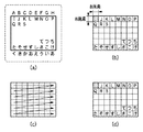
図2はカメラを横位置で撮影した場合の処理を示し、撮影時の被写体領域と図1の撮像部13の出力画像と、第1メモリ142及び第2メモリ143の記憶内容との関係を示している。ここでは、撮影時の姿勢に基づく信号処理内容の差が明確となるように、複数の文字が書き込まれている平面を被写体領域とした場合について説明する。
FIG. 2 shows the processing when the camera is photographed in the horizontal position, and shows the relationship between the subject area at the time of photographing, the output image of the
図2(a)において、破線で囲まれた領域は「A〜S」および「て〜あ」なる文字情報がある平面からなる被写体領域を示す。また実線で囲まれた領域はカメラファインダーからの観察領域であって、撮像領域と一致している。ここでは「A〜H」および「く〜あ」なる文字情報は撮像領域の外にあり、撮像されない。図2(b)は撮像素子から出力される画像データの概念図であって、「A〜H」および「く〜あ」なる文字情報が撮像されていないことが判る。 In FIG. 2A, an area surrounded by a broken line indicates a subject area consisting of a plane having character information “A to S” and “te to a”. An area surrounded by a solid line is an observation area from the camera finder and coincides with the imaging area. Here, the character information “A to H” and “ku to a” are outside the imaging region and are not imaged. FIG. 2B is a conceptual diagram of image data output from the image sensor, and it is understood that character information “A to H” and “ku to a” are not captured.
この撮像された画像の画像データは、撮像素子から読み出された順に、原画処理部141の一連の処理によりR、G、Bの各色成分に分離され、第1メモリ142に各色成分毎に記憶される。
The image data of the captured image is separated into R, G, and B color components by a series of processes of the original
図2(c)は、8×8画素を1単位として第1メモリ142から読み出す順番を示しており、横位置で撮影した場合、第1メモリ142から読み出す順番は矢印で示すように、その撮像している8×8画素の領域が「I」〜「P」、「Q」〜「S」〜「て」〜「ち」、「た」〜「け」という順に行う。このように、8×8画素を単位として、ラスタスキャンからジグザグスキャンへ変換して第1メモリ142からの読み出しを行う。なお、撮像素子からの読み出し単位を8×8画素としているのは、符号化部10および回転処理とのインターフェースに起因し、特に、符号化部10における符号化圧縮の処理単位で行うことが処理の速度から鑑みて好ましいからである。
FIG. 2C shows the order of reading out from the
第1メモリ142から読み出した画像データは、回転処理部7内のワークレジスタA71に転送された後、スイッチ74を介して符号化部10へ送られ、符号化処理の後、第2メモリ143へ格納される。この時、スイッチ74は「0」側を選択し、ワークレジスタA71からの出力データを選択するようになっている。
The image data read from the
上述した順番で読み出した場合に、第2メモリ143へ格納された時の画像データの様子を図2(d)に示す。
FIG. 2D shows the state of the image data when it is stored in the
図2に示すように、カメラを横位置で撮影した場合には、例えば「け」は第1メモリ142と第2メモリ143へ格納された時とも右下端にあり、同じようにして「I」は左上端にあり、8×8画素からなる複数のブロックのメモリ上の相対位置関係は変わらない。なお、第2メモリ143には符号化処理後のデータが格納されるので、この図2(d)は、第1メモリ142の内容と比較し易く示した第2メモリ143の内容についての概念図である。
As shown in FIG. 2, when the camera is photographed in the horizontal position, for example, “K” is at the lower right corner when stored in the
また、画像信号を第1メモリ142から読み出し、第2メモリ143へ格納するまでの処理は、R成分、G成分、B成分の各色成分について、1画面分ずつ順に行っているものとする。
Further, it is assumed that the processing from reading the image signal from the
このように、横位置で撮影した場合には、ワークレジスタA71は第1メモリ142から符号化部10へデータを送る際の一時記憶メモリの機能として符号化処理に関わる処理速度向上の役割を果たしている。
As described above, when the image is taken in the horizontal position, the work register A71 plays a role of improving the processing speed related to the encoding process as a function of the temporary storage memory when sending data from the
次に、縦位置で撮影した場合の処理について、図3を参照して説明する。図3では、カメラを右に90°回転して縦位置で撮影しているものとし、図2(a)の撮像領域の上辺が、図3(a)の撮像領域の右辺に対応する。また、図2と同様に破線で囲まれた「A〜S」および「て〜あ」なる文字情報がある平面からなる被写体領域を撮影しているものとし、図3(a)の実線で囲まれた領域はカメラファインダーからの観察領域を示す。縦位置では「A、I、Q、H、P」及び「た、く、ち、け、あ」なる文字情報が撮像領域の外にあり、撮像されない。 Next, processing when photographing in the vertical position will be described with reference to FIG. In FIG. 3, it is assumed that the camera is rotated 90 ° to the right and the image is taken in the vertical position, and the upper side of the imaging area in FIG. 2A corresponds to the right side of the imaging area in FIG. Similarly to FIG. 2, it is assumed that a subject area consisting of a plane having character information “A to S” and “te to a” surrounded by broken lines is photographed, and is surrounded by a solid line in FIG. The region shown is an observation region from the camera finder. In the vertical position, the character information “A, I, Q, H, P” and “ta, k, chi, ke, a” are outside the imaging region and are not imaged.
この撮像された画像の画像データは、撮像素子から読み出された順に、原画処理部141の一連の処理によりR、G、Bの各色成分毎に分離され、第1メモリ142に記憶される。図3(a)に示す撮像領域の見かけ上の1水平ラインは、例えば1ライン目では「B、C、D、E、F、G」であるが、実際には図2(a)の撮像領域の上辺に対応するラインから読み出されるので、図3(b)に示すように「G、O、…、つ、こ、い」のようになる。この結果、図3(a)に示す撮像領域の見かけ上の各水平ラインのデータが、第1メモリ142の各カラムに順に格納されている格好となる。更に、撮像された各文字は左に90°回転したものとなる。
The image data of the captured image is separated for each color component of R, G, and B by a series of processes of the original
図3(c)は、8×8画素を1単位として第1メモリ142から読み出す順番を示しており、図3(b)の左下端部にあたる「B」なる撮像内容である8×8画素ブロックから読み出しを始め、右上端部にあたる「い」なる撮像内容を読み出し最後の8×8画素ブロックとする。このように、8×8画素を単位として、ラスタスキャンからジグザグスキャンへ変換して第1メモリ142からの読み出しを行うが、読み出す順番を、横位置で撮影した場合とは異なるように制御する。
FIG. 3C shows an order of reading from the
第1メモリ142から読み出した画像データは、回転処理部7内のワークレジスタA71に転送されたる。図3(d)は、第1メモリ142から読み出された8×8画素単位のデータ順を示す概念図である。図3(d)に示すように、読み出した8×8画素単位の画像データは、左方向に90°回転したデータであるので、データ列変換部72により各8×8画素毎に右90°の回転処理を行って、ワークレジスタB73に格納する。
The image data read from the
ここで、図4から図6を参照して、回転処理部7における縦位置で撮影が行われた場合の8×8画素分の画像データの回転処理について説明する。
Here, with reference to FIG. 4 to FIG. 6, the rotation processing of the image data for 8 × 8 pixels when the
図4は第1メモリ142から読み出した8×8画素の画像データをワークレジスタA71へ格納する処理を説明する図である。
FIG. 4 is a diagram for explaining processing for storing 8 × 8 pixel image data read from the
まず、第1メモリ142から図3(c)に示す読み出し順で8×8画素単位で画像データが読み出されるが、ワークレジスタA71には、図3(d)に示すようにまだ回転処理が行われていない状態で、各画素の行順に続けて画像データが記憶される。図4では、画素の配列順位を判り易くするために、「△」などのシンボルを当てはめている。また、図4において、H1〜H8は画素単位内の行を示し、nは8×8画素単位のブロックの左上の画素が、図3(b)に示す全体画像において、左から何番目の画素にあたるかを示す。例えば、図3(b)において「G」の文字情報を撮像した領域の場合には、図4のnは「1」であり、「O」であればnは「9」となる。
First, image data is read from the
図5は、データ列変換部72により行われる回転処理を説明する図である。図5に示すように、図4で説明したようにして、8×8画素単位のH1〜H8がワークレジスタ71Aの第1〜第64格納領域に格納される。
FIG. 5 is a diagram illustrating the rotation process performed by the data
ワークレジスタA71の第1〜第64格納領域に各画素のデータが格納された後、まず、図5(a)に示すように、H1〜H8の各行の先頭位置にある画素のデータのみを、H8行目からH1行目までワークレジスタB72に転送する。具体的には、まず、H8行目の先頭位置にある画素のデータを読み出してワークレジスタB73の第1レジスタに格納し、次に、H7行目の先頭位置にある画素のデータを第2レジスタに格納すると言うように、H1行目の先頭位置にある画素のデータまで順次転送する。つまり、第(8N+1)格納領域にあるデータを、N=7から0の順に転送し、ワークレジスタB73の第1〜第8レジスタに格納する。 After the data of each pixel is stored in the first to 64th storage areas of the work register A71, first, as shown in FIG. 5 (a), only the data of the pixel at the head position of each row of H1 to H8 is obtained. Transfer from the H8 line to the H1 line to the work register B72. Specifically, first, the pixel data at the head position of the H8th row is read and stored in the first register of the work register B73, and then the pixel data at the head position of the H7th row is stored in the second register. The data of the pixel at the head position of the H1 line are sequentially transferred. That is, the data in the (8N + 1) th storage area is transferred in the order of N = 7 to 0 and stored in the first to eighth registers of the work register B73.
同様にして、図5(b)に示すように、H1〜H8の各行の先頭から2番目の位置にある画素のデータのみをワークレジスタB73に転送する。つまり、第(8N+2)格納領域にあるデータを、N=7から0の順に転送し、ワークレジスタB73の第9〜第16レジスタに格納する。 Similarly, as shown in FIG. 5B, only the pixel data at the second position from the top of each row of H1 to H8 is transferred to the work register B73. That is, the data in the (8N + 2) storage area is transferred in the order of N = 7 to 0 and stored in the ninth to sixteenth registers of the work register B73.
同様の処理を各行の最後の位置にある画素のデータを転送するまで繰り返し、図5(c)に示すように、H1〜H8の各行の先頭から第8の位置にある画素のデータのみをワークレジスタB73に転送する。つまり、第(8N+8)格納領域にあるデータを、N=7から0の順に転送し、ワークレジスタB73の第57〜第64レジスタに格納する。 Similar processing is repeated until the data of the pixel at the last position in each row is transferred, and only the data of the pixel at the eighth position from the head of each row of H1 to H8 is processed as shown in FIG. Transfer to register B73. That is, the data in the (8N + 8) th storage area is transferred in the order of N = 7 to 0 and stored in the 57th to 64th registers of the work register B73.
上述したようにして、ワークレジスタA71の画像データをワークレジスタB73の第64レジスタまで格納した状態を図6に示す。図4と比較すると、この時点で、右方向へ90°の回転処理が完了していることが分かる。 FIG. 6 shows a state where the image data of the work register A71 is stored up to the 64th register of the work register B73 as described above. Compared with FIG. 4, it can be seen that the rotation process of 90 ° rightward is completed at this point.
このように、ワークレジスタB73に回転後の8×8画素の画像データが揃うと、符号化部10へ出力され、順次符号化圧縮処理が施され、第2メモリ143に格納される。なおこの時、スイッチ74は「1」側を選択し、ワークレジスタB73からの出力データを選択するようになっている。
As described above, when the rotated 8 × 8 pixel image data is prepared in the
上述した縦位置での撮像時の処理においては、ワークレジスタA71は第1メモリ142からデータ列変換部72へデータを送る際の一時記憶メモリの機能として処理速度向上の役割を果たし、ワークレジスタB73はデータ列変換部72から符号化部10へデータを送る際の一時記憶メモリの機能として処理速度向上の役割を果たすとともに、第1メモリ142から符号化処理に関わる処理速度向上の役割も果たしている。
In the above-described processing at the time of imaging in the vertical position, the work register A71 serves as a function of a temporary storage memory when data is sent from the
図3(e)は第2メモリ143へ格納された際の8×8画素ブロックの配置イメージを示す。なお、第2メモリ143へ格納された際の「配置イメージ」と呼ぶのは、符号化部10において符号化圧縮処理が行われるために、実際には第2メモリ143上には異なる形態で画像データが格納されるからである。
FIG. 3E shows an arrangement image of 8 × 8 pixel blocks when stored in the
第2メモリ143では、上記回転処理及び符号化圧縮処理された8×8画素ブロックの画像データを順次保存する。これにより、例えば、図3(b)に示すように撮像時に左下端にあった「B」は、図3(e)に示すように第2メモリ143上では左上端となり、図3(b)において左上端にある「G」は、図3(e)に示すように第2メモリ143上では1行目の6列目となる。
The
また、図3(b)に示すように撮像時に左下端から2番目にあった「J」と、その上にあった「K」は、それぞれ図3(e)に示すように、第2メモリ143の右上端から2番目と右上端にそれぞれ格納される。 Further, as shown in FIG. 3B, “J” that is second from the lower left corner at the time of imaging and “K” that is on it are the second memory as shown in FIG. 143 is stored in the second and upper right ends from the upper right end, respectively.
このように、第2メモリ143へは、図3(e)に示す順番で画像データが記憶されるため、図3(b)に示す撮像時とは8×8画素からなる各ブロックの相対位置関係が異なる。
Thus, since the image data is stored in the
また、第2メモリ143において符号化された画像情報のヘッダーに撮影時の姿勢情報を付加することで、再生する画像の撮影時の姿勢が判るようになっているので、図3(e)に示すように画像データを記憶しても、正しい幅及び高さを有する縦位置の画像を再生することができる。
Further, by adding the posture information at the time of shooting to the header of the image information encoded in the
なお、符号化処理で必要となる、圧縮率や記録する映像の大きさ及び出力データ形式等の設定は、例えば、撮影前に撮影者によって設定されていた値を、シャッタースイッチが押された時点でPRS140が符号化部10へ送ることで行う。
Note that the settings required for the encoding process, such as the compression rate, the size of the video to be recorded, and the output data format, are the values set by the photographer before shooting, for example, when the shutter switch is pressed. This is done by sending the
また、上記第1の実施形態では8×8画素毎に回転処理を行ったが、所定の単位で回転処理を行うようにすれば、大きなワークレジスタを必要とすることなく、回転処理が可能となる。なお、後段の符号化部10とのインターフェースに対応するレジスタ容量にすることで、最適な容量となり、効率的に符号化処理を含む処理を行うことができる。
In the first embodiment, the rotation process is performed every 8 × 8 pixels. However, if the rotation process is performed in a predetermined unit, the rotation process can be performed without requiring a large work register. Become. Note that by setting the register capacity corresponding to the interface with the
図7は、本第1の実施形態においてカメラを縦位置にて撮影した場合の、撮影時の観測状態及び撮像素子からの出力画像、TV等の表示装置への表示の内容を示す。 FIG. 7 shows the observation state at the time of photographing, the output image from the image sensor, and the content displayed on a display device such as a TV when the camera is photographed in the vertical position in the first embodiment.
図7(a)は、カメラ接眼部からファイダを覗いた場合の撮影領域の観察画像を示し、 AFP1〜AFP3は3つの測距点を示している。ここでは、測距点 AFP3で焦点調節している。図7(b)は、撮像素子から出力される画像データの概念図、図7(c)はTV等の表示装置に表示された表示画像を示している。 FIG. 7A shows an observation image of the imaging region when looking through the finder from the camera eyepiece, and AFP1 to AFP3 show three distance measuring points. Here, the focus is adjusted by the distance measuring point AFP3. FIG. 7B is a conceptual diagram of image data output from the image sensor, and FIG. 7C shows a display image displayed on a display device such as a TV.
図7は、カメラを縦位置にて撮影した場合であるため、図7(b)で示すように撮像素子から出力される画像は左方向に90°の横倒しになっているが、これを上述した本第1の実施形態の方法で右方向に90°回転処理を行った後の出力画像は、図7(c)のようになる。 Since FIG. 7 shows a case where the camera is photographed in the vertical position, as shown in FIG. 7B, the image output from the image sensor is laid down by 90 ° in the left direction. The output image after the 90 ° rotation processing in the right direction by the method of the first embodiment is as shown in FIG.
通常、モニタの画面は横長であるので、90°回転処理を行った後の出力画像は、高さがモニタ画面の高さと一致するように縮小処理を行ってから表示される。その場合、モニタ画面の左右に無い空き領域ができるが、その領域に例えば、単色表示を行うようにしても良い。 Usually, since the monitor screen is horizontally long, the output image after 90 ° rotation processing is displayed after reduction processing so that the height matches the height of the monitor screen. In this case, empty areas that do not exist on the left and right sides of the monitor screen are formed, but for example, monochrome display may be performed in those areas.
上記通り、本第1の実施形態によれば、撮影時のカメラの姿勢に応じて、縦位置で撮影した画像データを回転処理した後に圧縮符号化して記憶装置へ記録するため、表示再生の際の回転処理が不要になり、縦位置表示のための処理にかかる時間を短縮することができる。 As described above, according to the first embodiment, image data captured at a vertical position is subjected to rotation processing and then compressed and encoded and recorded in a storage device in accordance with the orientation of the camera at the time of shooting. Rotation processing is not necessary, and the time required for processing for vertical position display can be shortened.
また、画像データを回転処理する回転処理単位領域と符号化処理を行う単位領域の大きさを共通化したので、回転処理と符号化を単位領域毎に連続に行うことができ、装置が簡単になるとともに、撮像から符号化までの処理時間を短縮することができる。また、撮像素子の高画素化にも対応することができる。 In addition, since the size of the rotation processing unit area for rotating image data and the size of the unit area for encoding processing are made common, rotation processing and encoding can be performed continuously for each unit area, and the apparatus can be simplified. In addition, the processing time from imaging to encoding can be shortened. Further, it is possible to cope with an increase in the number of pixels of the image sensor.
<第2の実施形態>
以下、本発明の第2の実施形態を図面を参照して説明する。
<Second Embodiment>
Hereinafter, a second embodiment of the present invention will be described with reference to the drawings.
上記第1の実施形態では、回転処理後に符号化を行っていた。これに対し、本第2の実施形態では、回転処理後の符号化処理を無くしたものである。 In the first embodiment, encoding is performed after the rotation process. On the other hand, in the second embodiment, the encoding process after the rotation process is eliminated.
図8は第2の実施形態における撮像装置の構成を示す。図8は図1から符号化部10を取り除いたものであり、他の構成は第1の実施形態の図1と同じであるので、ここではその説明を省略する。
FIG. 8 shows a configuration of an imaging apparatus according to the second embodiment. FIG. 8 is obtained by removing the
このように、撮像部13から出力される画像情報の大きさもによるが、第2の実施形態によれば、符号化処理を無くすことにより、回転処理された画像を画像の劣化なく記憶部9へ送ることができる。
As described above, depending on the size of the image information output from the
上記通り、本第2の実施形態によれば、撮影時のカメラの姿勢に応じて、縦位置で撮影した画像データを回転処理した後に記憶装置へ記録するため、表示再生の際の回転処理が不要になり、縦位置表示のための処理にかかる時間を短縮することができる。また、符号化処理を行わないため、画質の劣化無く画像を記憶し、再生表示することができる。 As described above, according to the second embodiment, according to the orientation of the camera at the time of shooting, the image data shot at the vertical position is rotated and then recorded in the storage device. It becomes unnecessary, and the time required for the processing for displaying the vertical position can be shortened. Further, since the encoding process is not performed, the image can be stored and reproduced and displayed without deterioration in image quality.
<第3の実施形態>
以下、本発明の第3の実施形態を図面を参照して説明する。
<Third Embodiment>
Hereinafter, a third embodiment of the present invention will be described with reference to the drawings.
第1の実施形態では、回転処理後に符号化した後、一度メモリへ格納してから記憶部9へ出力するものであった。これに対し、本第3の実施形態では、回転処理後にメモリへ格納した後、符号化処理を行い、符号化処理後の出力をメモリに一旦格納すること無く、記憶部9へ出力する。
In the first embodiment, after encoding after the rotation process, the data is once stored in the memory and then output to the
図9に第3の実施形態における画像処理装置の構成を示す。 FIG. 9 shows the configuration of the image processing apparatus according to the third embodiment.
図9では図1の構成から第2メモリ143を取り除き、FIFOメモリを2つ挿入した構成である。また、FIFOメモリを2つ挿入したことに伴って、いずれかのFIFOメモリを選択するスイッチが2つ追加されている。それ以外の構成は、第1の実施形態の図1と同じであるので、ここではその説明を省略し、FIFOメモリから後段の処理について説明する。
In FIG. 9, the
縦位置で撮影を行った場合、第1の実施形態で説明したようにして回転処理部7によりR、G、Bの各色成分について、そのいずれかから、8×8画素を1単位とする回転処理を行い、その出力はスイッチ301を介して2つのFIFOメモリ302または303のいずれか一方に入力される。
When shooting in the vertical position, as described in the first embodiment, the
8×8画素分のデータの格納が完了すると、スイッチ301はもう一方のFIFOメモリへ出力先を切り換える。そして次の回転処理が行われるとその出力が切り換えた先のFIFOメモリへ格納され、既に格納完了しているFIFOメモリは、スイッチ304を介して順次符号化部10へその内容を出力する。符号化部10に入力された画像データは、符号化されて記憶部9に出力される。
When the storage of data for 8 × 8 pixels is completed, the
FIFOメモリ302、303はそれぞれ64画素分(8×8画素分)の容量を持ち、2つのFIFOメモリ302、303がスイッチ301、302により交互に切り換わって、パイプライン処理の如く動作する。
The
また、この時、第1メモリ142から符号化部10までの1画素あたりの処理速度は同じにする必要があるため、いずれかの最も速度の遅いブロックに支配される処理速度で処理が行われるが、回転処理部7から符号化部10の受け渡しを行うメモリがFIFOメモリであるから、コスト的なメリットが得られる。
At this time, since the processing speed per pixel from the
上記の通り、本第3の実施形態によれば、撮影時のカメラの姿勢に応じて、縦位置で撮影した画像データを回転処理した後に圧縮符号化して記憶装置へ記録するため、表示再生の際の回転処理が不要になり、縦位置表示のための処理にかかる時間を短縮することができる。 As described above, according to the third embodiment, the image data captured in the vertical position is subjected to the rotation process after being subjected to the rotation process, and then compressed and recorded in the storage device according to the posture of the camera at the time of shooting. Rotation processing at the time is not necessary, and the time required for processing for vertical position display can be shortened.
なお、上記第1から第3の実施形態において、回転処理を行う対象の信号は、RGBの色成分でなくとも、本発明の機能が達成できる信号であればどのようなものであっても良いことは言うまでもない。 In the first to third embodiments, the signal to be subjected to the rotation process may be any signal that can achieve the function of the present invention, even if it is not an RGB color component. Needless to say.
また、本発明は、デジタルカメラに限らず、カメラ以外の光学機器や他の装置などの、2次元に配設された光電変換素子により撮像されて得られた画像信号を変換して、最終的に例えばモニタやプリンタ等の出力装置へ出力するものであれば適用することができる。 In addition, the present invention is not limited to a digital camera, and finally converts an image signal obtained by imaging with a two-dimensionally arranged photoelectric conversion element such as an optical device or other device other than a camera, and finally For example, any device that outputs to an output device such as a monitor or a printer can be applied.
また、画像の回転も時計方向に90°のみではなく、反時計方向に90°への回転処理へも容易に対応することが可能であることは、当業者には明らかである。 It is obvious to those skilled in the art that the image can be easily rotated not only in the clockwise direction of 90 ° but also in the counterclockwise direction of 90 °.
また、本発明は、複数の機器(例えばホストコンピュータ、インターフェイス機器、カメラヘッドなど)から構成されるシステムに適用しても、一つの機器からなる装置(例えば、デジタルスチルカメラ、デジタルビデオカメラなど)に適用してもよい。 Further, the present invention can be applied to a system constituted by a plurality of devices (for example, a host computer, an interface device, a camera head, etc.), and a device (for example, a digital still camera, a digital video camera, etc.) comprising a single device. You may apply to.
また、本発明の目的は、前述した実施形態の機能を実現するソフトウェアのプログラムコードを記録した記憶媒体(または記録媒体)を、システムあるいは装置に供給し、そのシステムあるいは装置のコンピュータ(またはCPUやMPU)が記憶媒体に格納されたプログラムコードを読み出し実行することによっても、達成されることは言うまでもない。この場合、記憶媒体から読み出されたプログラムコード自体が前述した実施形態の機能を実現することになり、そのプログラムコードを記憶した記憶媒体は本発明を構成することになる。また、コンピュータが読み出したプログラムコードを実行することにより、前述した実施形態の機能が実現されるだけでなく、そのプログラムコードの指示に基づき、コンピュータ上で稼働しているオペレーティングシステム(OS)などが実際の処理の一部または全部を行い、その処理によって前述した実施形態の機能が実現される場合も含まれることは言うまでもない。ここでプログラムコードを記憶する記憶媒体としては、例えば、フレキシブルディスク、ハードディスク、ROM、RAM、磁気テープ、不揮発性のメモリカード、CD−ROM、CD−R、DVD、光ディスク、光磁気ディスク、MOなどが考えられる。また、LAN(ローカル・エリア・ネットワーク)やWAN(ワイド・エリア・ネットワーク)などのコンピュータネットワークを、プログラムコードを供給するために用いることができる。 Another object of the present invention is to supply a storage medium (or recording medium) in which a program code of software that realizes the functions of the above-described embodiments is recorded to a system or apparatus, and the computer (or CPU or CPU) of the system or apparatus. Needless to say, this can also be achieved by the MPU) reading and executing the program code stored in the storage medium. In this case, the program code itself read from the storage medium realizes the functions of the above-described embodiments, and the storage medium storing the program code constitutes the present invention. Further, by executing the program code read by the computer, not only the functions of the above-described embodiments are realized, but also an operating system (OS) running on the computer based on the instruction of the program code. It goes without saying that a case where the function of the above-described embodiment is realized by performing part or all of the actual processing and the processing is included. Examples of the storage medium for storing the program code include a flexible disk, hard disk, ROM, RAM, magnetic tape, nonvolatile memory card, CD-ROM, CD-R, DVD, optical disk, magneto-optical disk, MO, and the like. Can be considered. Also, a computer network such as a LAN (Local Area Network) or a WAN (Wide Area Network) can be used to supply the program code.
さらに、記憶媒体から読み出されたプログラムコードが、コンピュータに挿入された機能拡張カードやコンピュータに接続された機能拡張ユニットに備わるメモリに書込まれた後、そのプログラムコードの指示に基づき、その機能拡張カードや機能拡張ユニットに備わるCPUなどが実際の処理の一部または全部を行い、その処理によって前述した実施形態の機能が実現される場合も含まれることは言うまでもない。 Furthermore, after the program code read from the storage medium is written into a memory provided in a function expansion card inserted into the computer or a function expansion unit connected to the computer, the function is determined based on the instruction of the program code. It goes without saying that the CPU or the like provided in the expansion card or the function expansion unit performs part or all of the actual processing and the functions of the above-described embodiments are realized by the processing.
6 表示部
7 回転処理部
8 姿勢検出部
9 記憶部
10 符号化部
13 撮像部
71 ワークレジスタA
72 データ列変換部
73 ワークレジスタB
74 スイッチ
101〜104 スイッチ
140 マイコン
141 原画処理部
142 第1メモリ
143 第2メモリ
144 表示メモリ
301、304 スイッチ
302、303 FIFOメモリ
6
72
74
Claims (7)
前記撮像装置から出力される画像データを1フレーム分記憶するメモリと、
前記画像データが撮像されたときの前記撮像装置の姿勢情報を検出する姿勢情報検出手段と、
前記姿勢情報検出手段により検出された前記姿勢情報が縦位置である場合に、前記メモリに記憶された画像データを、横i個、縦j個のi×j個に分割された領域それぞれを構成する所定画素数単位ずつ、第1の方向に順に読み出し、読み出した前記所定画素数単位毎の画像データに順次回転処理を行う回転手段と、
前記姿勢情報が縦位置である場合には前記回転手段により処理された画像データを、前記姿勢情報が横位置である場合には前記メモリに記憶された画像データを前記第1の方向と前記姿勢情報とに基づいた第2の方向に前記所定画素数単位ずつ順に読み出された画像データを、各領域が前記所定画素数単位であるi×j個の領域に、前記第2の方向に順次記憶する記憶手段と、
前記姿勢情報が縦位置である場合に、前記回転手段により処理され、前記記憶手段に記憶された画像データを縦位置で表示させるための姿勢情報を、前記画像データと共に前記記憶手段に記憶させる姿勢情報付加手段と
を有することを特徴とする画像処理装置。 An image processing device that processes image data captured by an imaging device having an imaging device in which a plurality of photoelectric conversion elements are two-dimensionally arranged and outputs an electrical signal according to an incident light amount,
A memory for storing image data output from the imaging device for one frame;
Attitude information detection means for detecting attitude information of the imaging device when the image data is captured;
If the attitude information detected by the posture information detecting means is a vertical position, constituting the image data stored in said memory, horizontal i pieces, each vertical the j i × divided into the j region Rotating means for sequentially reading in units of a predetermined number of pixels in the first direction and sequentially rotating the read image data for each predetermined number of pixels;
When the posture information is a vertical position, the image data processed by the rotating means is used. When the posture information is a horizontal position, the image data stored in the memory is used as the first direction and the posture. the image data that has been read out one by the predetermined number of pixels units in the second direction based on the information, the i × j number of regions each region is the predetermined number of pixels units, sequentially in the second direction Storage means for storing;
When the posture information is the vertical position, the posture information for displaying the image data processed by the rotating unit and stored in the storage unit in the vertical position is stored in the storage unit together with the image data. An image processing apparatus comprising: an information adding unit.
前記回転処理に先立って、前記所定画素数単位分の画像データを記憶する、前記所定画素単位分の容量を有する第1の記憶手段と、
前記回転処理後の画像データを記憶する、前記所定画素数単位分の容量を有する第2の記憶手段と
を有することを特徴とする請求項1に記載の画像処理装置。 The rotating means includes
Prior to the rotation processing, first storage means for storing the image data for the predetermined number of pixels unit and having a capacity for the predetermined pixel unit;
The image processing apparatus according to claim 1, further comprising: a second storage unit that stores the image data after the rotation process and has a capacity corresponding to the predetermined number of pixels.
前記撮像素子から出力される画像データを1フレーム分記憶するメモリと、
前記画像データが撮像されたときの前記撮像装置の姿勢を検出する姿勢検出手段と、
前記姿勢検出手段により検出された前記姿勢が縦位置である場合に、前記メモリに記憶された画像データを、横i個、縦j個のi×j個に分割された領域それぞれを構成する所定画素数単位ずつ、第1の方向に順に読み出し、読み出した前記所定画素数単位毎の画像データに順次回転処理を行う回転手段と、
前記姿勢情報が縦位置である場合には前記回転手段により処理された画像データを、前記姿勢情報が横位置である場合には前記メモリに記憶された画像データを前記第1の方向と前記姿勢情報とに基づいた第2の方向に前記所定画素数単位ずつ順に読み出された画像データを、各領域が前記所定画素数単位であるi×j個の領域に、前記第2の方向に順次記憶する記憶手段と、
前記姿勢情報が縦位置である場合に、前記回転手段により処理され、前記記憶手段に記憶された画像データを縦位置で表示させるための姿勢情報を、前記画像データと共に前記記憶手段に記憶させる姿勢情報付加手段と
を有することを特徴とする撮像装置。 An image pickup apparatus in which a plurality of photoelectric conversion elements are two-dimensionally arranged to pick up an image with an image pickup element that outputs image data according to the amount of incident light,
A memory for storing one frame of image data output from the image sensor;
Attitude detection means for detecting the attitude of the imaging device when the image data is imaged;
When the posture detected by the posture detection means is a vertical position, the image data stored in the memory is predetermined to constitute each of an area divided into i × j and j × j. Rotating means for sequentially reading out the image data in units of the number of pixels in the first direction and sequentially rotating the read image data for each unit of the number of pixels.
When the posture information is a vertical position, the image data processed by the rotating means is used. When the posture information is a horizontal position, the image data stored in the memory is used as the first direction and the posture. the image data that has been read out one by the predetermined number of pixels units in the second direction based on the information, the i × j number of regions each region is the predetermined number of pixels units, sequentially in the second direction Storage means for storing;
When the posture information is the vertical position, the posture information for displaying the image data processed by the rotating unit and stored in the storage unit in the vertical position is stored in the storage unit together with the image data. An image pickup apparatus comprising: an information adding unit.
前記撮像装置から出力される画像データをメモリに1フレーム分記憶する第1の記憶工程と、
前記画像データが撮像されたときの前記撮像装置の姿勢情報を検出する姿勢情報検出工程と、
前記姿勢情報検出工程で検出された前記姿勢情報が縦位置である場合に、前記メモリに記憶された画像データを、横i個、縦j個のi×j個に分割された領域それぞれを構成する所定画素数単位ずつ、第1の方向に順に読み出し、読み出した前記所定画素数単位毎の画像データに順次回転処理を行う回転工程と、
前記姿勢情報が縦位置である場合には前記回転工程で処理された画像データを、前記姿勢情報が横位置である場合には前記メモリに記憶された画像データを前記第1の方向と前記姿勢情報とに基づいた第2の方向に前記所定画素数単位ずつ順に読み出された画像データを、各領域が前記所定画素数単位であるi×j個の領域に、前記第2の方向に順次記憶手段に記憶する第2の記憶工程と、
前記姿勢情報が縦位置である場合に、前記回転工程で処理され、前記記憶手段に記憶された画像データを縦位置で表示させるための姿勢情報を、前記画像データと共に前記記憶手段に記憶させる姿勢情報付加工程と
を有することを特徴とする画像処理方法。 An image processing method for processing image data picked up by an image pickup apparatus having an image pickup element in which a plurality of photoelectric conversion elements are arranged two-dimensionally and outputs an electric signal according to an incident light amount,
A first storage step of storing image data output from the imaging device in a memory for one frame;
A posture information detection step of detecting posture information of the imaging device when the image data is captured;
If the attitude information detected by the attitude information detection process is the vertical position, constituting the image data stored in said memory, horizontal i pieces, each vertical the j i × divided into the j region A rotation step of sequentially reading in units of a predetermined number of pixels in the first direction, and sequentially rotating the read image data for each predetermined number of pixels;
When the posture information is a vertical position, the image data processed in the rotation step is used. When the posture information is a horizontal position, the image data stored in the memory is used as the first direction and the posture. the image data that has been read out one by the predetermined number of pixels units in the second direction based on the information, the i × j number of regions each region is the predetermined number of pixels units, sequentially in the second direction A second storage step for storing in the storage means;
When the posture information is the vertical position, the posture information for displaying the image data processed in the rotation step and stored in the storage unit in the vertical position is stored in the storage unit together with the image data. An image processing method comprising: an information adding step.
Priority Applications (2)
| Application Number | Priority Date | Filing Date | Title |
|---|---|---|---|
| JP2004228014A JP4579613B2 (en) | 2004-08-04 | 2004-08-04 | Image processing apparatus and method, and imaging apparatus |
| US11/191,033 US7433543B2 (en) | 2004-08-04 | 2005-07-28 | Image processing apparatus and method, and image sensing apparatus |
Applications Claiming Priority (1)
| Application Number | Priority Date | Filing Date | Title |
|---|---|---|---|
| JP2004228014A JP4579613B2 (en) | 2004-08-04 | 2004-08-04 | Image processing apparatus and method, and imaging apparatus |
Publications (3)
| Publication Number | Publication Date |
|---|---|
| JP2006050218A JP2006050218A (en) | 2006-02-16 |
| JP2006050218A5 JP2006050218A5 (en) | 2007-09-13 |
| JP4579613B2 true JP4579613B2 (en) | 2010-11-10 |
Family
ID=35757467
Family Applications (1)
| Application Number | Title | Priority Date | Filing Date |
|---|---|---|---|
| JP2004228014A Expired - Fee Related JP4579613B2 (en) | 2004-08-04 | 2004-08-04 | Image processing apparatus and method, and imaging apparatus |
Country Status (2)
| Country | Link |
|---|---|
| US (1) | US7433543B2 (en) |
| JP (1) | JP4579613B2 (en) |
Families Citing this family (12)
| Publication number | Priority date | Publication date | Assignee | Title |
|---|---|---|---|---|
| JP4346925B2 (en) * | 2003-02-25 | 2009-10-21 | キヤノン株式会社 | Display device, display device control method, program, and computer-readable recording medium |
| TWM328624U (en) * | 2007-10-05 | 2008-03-11 | Princeton Technology Corp | Image processing apparatus and image display system |
| CN101874408A (en) * | 2007-11-22 | 2010-10-27 | 日本电气株式会社 | Image capturing device, encoding method, and program |
| US9647851B2 (en) | 2008-10-13 | 2017-05-09 | Ppc Broadband, Inc. | Ingress noise inhibiting network interface device and method for cable television networks |
| KR20110061063A (en) * | 2009-12-01 | 2011-06-09 | 삼성전자주식회사 | Apparatus and method for photographing of a portable terminal |
| JP5668466B2 (en) * | 2010-12-28 | 2015-02-12 | ソニー株式会社 | Image processing apparatus, control method thereof, and program |
| MX351190B (en) | 2012-10-17 | 2017-10-05 | Ppc Broadband Inc | Network interface device and method having passive operation mode and noise management. |
| DE102013224590B4 (en) * | 2012-12-03 | 2019-07-18 | Canon Kabushiki Kaisha | DISPLAY DEVICE AND ITS CONTROL METHOD |
| US9741150B2 (en) | 2013-07-25 | 2017-08-22 | Duelight Llc | Systems and methods for displaying representative images |
| JP6161400B2 (en) * | 2013-05-17 | 2017-07-12 | キヤノン株式会社 | Video playback apparatus and control method thereof |
| JP6465625B2 (en) * | 2014-10-10 | 2019-02-06 | キヤノン株式会社 | Control device, control method therefor, and program |
| RU2685219C1 (en) * | 2018-08-27 | 2019-04-17 | Вячеслав Михайлович Смелков | Method of controlling the sensitivity of a television camera on a ccd matrix in conditions of complex lighting and / or complex brightness of objects |
Citations (2)
| Publication number | Priority date | Publication date | Assignee | Title |
|---|---|---|---|---|
| JP2002262155A (en) * | 2000-12-27 | 2002-09-13 | Matsushita Electric Ind Co Ltd | Image pickup device, display device and projector |
| JP2003283792A (en) * | 2002-03-22 | 2003-10-03 | Ricoh Co Ltd | Imaging apparatus and conversion method of image data |
Family Cites Families (8)
| Publication number | Priority date | Publication date | Assignee | Title |
|---|---|---|---|---|
| JPH08336069A (en) * | 1995-04-13 | 1996-12-17 | Eastman Kodak Co | Electronic still camera |
| JPH10233993A (en) | 1997-02-19 | 1998-09-02 | Kawasaki Steel Corp | Electronic still camera |
| JP3655734B2 (en) | 1997-06-04 | 2005-06-02 | ペンタックス株式会社 | Image compression apparatus and image display apparatus |
| US6597817B1 (en) * | 1997-07-15 | 2003-07-22 | Silverbrook Research Pty Ltd | Orientation detection for digital cameras |
| US6262769B1 (en) * | 1997-07-31 | 2001-07-17 | Flashpoint Technology, Inc. | Method and system for auto rotating a graphical user interface for managing portrait and landscape images in an image capture unit |
| US6148149A (en) * | 1998-05-26 | 2000-11-14 | Microsoft Corporation | Automatic image rotation in digital cameras |
| US6330374B1 (en) * | 1998-11-13 | 2001-12-11 | Ricoh Company, Ltd. | Image manipulation for a digital copier which operates on a block basis |
| JP3824440B2 (en) * | 1999-03-09 | 2006-09-20 | 三菱電機株式会社 | Imaging device |
-
2004
- 2004-08-04 JP JP2004228014A patent/JP4579613B2/en not_active Expired - Fee Related
-
2005
- 2005-07-28 US US11/191,033 patent/US7433543B2/en not_active Expired - Fee Related
Patent Citations (2)
| Publication number | Priority date | Publication date | Assignee | Title |
|---|---|---|---|---|
| JP2002262155A (en) * | 2000-12-27 | 2002-09-13 | Matsushita Electric Ind Co Ltd | Image pickup device, display device and projector |
| JP2003283792A (en) * | 2002-03-22 | 2003-10-03 | Ricoh Co Ltd | Imaging apparatus and conversion method of image data |
Also Published As
| Publication number | Publication date |
|---|---|
| US7433543B2 (en) | 2008-10-07 |
| US20060029292A1 (en) | 2006-02-09 |
| JP2006050218A (en) | 2006-02-16 |
Similar Documents
| Publication | Publication Date | Title |
|---|---|---|
| JP4350809B2 (en) | Digital camera | |
| US7433543B2 (en) | Image processing apparatus and method, and image sensing apparatus | |
| JP4560422B2 (en) | Imaging apparatus and control method thereof | |
| JP3822380B2 (en) | Image signal processing device | |
| KR100673277B1 (en) | Image data processing method, image data processing apparatus and digital still camera | |
| JPH06350951A (en) | Picture signal processing unit | |
| US8379093B2 (en) | Recording and reproduction apparatus and methods, and a recording medium storing a computer program for executing the methods | |
| JP2006211426A (en) | Image sensing device and its image generating method | |
| KR101480406B1 (en) | Recording apparatus, replaying apparatus, recording method, replaying method and program recording medium | |
| JP2007067708A (en) | Imaging apparatus and method of forming image by it | |
| US6774940B1 (en) | Electronic camera apparatus having image reproducing function and method for controlling reproduction thereof | |
| JP2001203969A (en) | Image pickup device and its operation control method | |
| JP2011029809A (en) | Image processing device, image processing method, and image capturing device | |
| JP3858447B2 (en) | Electronic camera device | |
| JP4430731B2 (en) | Digital camera and photographing method | |
| JP4256028B2 (en) | Compression encoding apparatus and method | |
| JP2000069418A (en) | Pixel number converter and digital camera device | |
| JP3815068B2 (en) | Electronic still camera and control method thereof | |
| JP4387264B2 (en) | Imaging apparatus and image generation method thereof | |
| JP2000197004A (en) | Device for recording animation | |
| JP2000138941A (en) | Encoding device, camera apparatus and recording method | |
| JPH06237431A (en) | Electronic still camera | |
| JP4310177B2 (en) | Imaging apparatus and imaging method | |
| JP3177473B2 (en) | Digital imaging device | |
| JP2005150835A (en) | Image processing apparatus, digital camera system, and digital camera |
Legal Events
| Date | Code | Title | Description |
|---|---|---|---|
| A521 | Request for written amendment filed |
Free format text: JAPANESE INTERMEDIATE CODE: A523 Effective date: 20070726 |
|
| A621 | Written request for application examination |
Free format text: JAPANESE INTERMEDIATE CODE: A621 Effective date: 20070726 |
|
| RD03 | Notification of appointment of power of attorney |
Free format text: JAPANESE INTERMEDIATE CODE: A7423 Effective date: 20070726 |
|
| A977 | Report on retrieval |
Free format text: JAPANESE INTERMEDIATE CODE: A971007 Effective date: 20091022 |
|
| A131 | Notification of reasons for refusal |
Free format text: JAPANESE INTERMEDIATE CODE: A131 Effective date: 20091030 |
|
| A521 | Request for written amendment filed |
Free format text: JAPANESE INTERMEDIATE CODE: A523 Effective date: 20091228 |
|
| A02 | Decision of refusal |
Free format text: JAPANESE INTERMEDIATE CODE: A02 Effective date: 20100308 |
|
| A521 | Request for written amendment filed |
Free format text: JAPANESE INTERMEDIATE CODE: A523 Effective date: 20100607 |
|
| A911 | Transfer to examiner for re-examination before appeal (zenchi) |
Free format text: JAPANESE INTERMEDIATE CODE: A911 Effective date: 20100616 |
|
| TRDD | Decision of grant or rejection written | ||
| A01 | Written decision to grant a patent or to grant a registration (utility model) |
Free format text: JAPANESE INTERMEDIATE CODE: A01 Effective date: 20100823 |
|
| A01 | Written decision to grant a patent or to grant a registration (utility model) |
Free format text: JAPANESE INTERMEDIATE CODE: A01 |
|
| A61 | First payment of annual fees (during grant procedure) |
Free format text: JAPANESE INTERMEDIATE CODE: A61 Effective date: 20100826 |
|
| FPAY | Renewal fee payment (event date is renewal date of database) |
Free format text: PAYMENT UNTIL: 20130903 Year of fee payment: 3 |
|
| R150 | Certificate of patent or registration of utility model |
Free format text: JAPANESE INTERMEDIATE CODE: R150 |
|
| LAPS | Cancellation because of no payment of annual fees |