JP4554185B2 - X-ray CT system - Google Patents
X-ray CT system Download PDFInfo
- Publication number
- JP4554185B2 JP4554185B2 JP2003387704A JP2003387704A JP4554185B2 JP 4554185 B2 JP4554185 B2 JP 4554185B2 JP 2003387704 A JP2003387704 A JP 2003387704A JP 2003387704 A JP2003387704 A JP 2003387704A JP 4554185 B2 JP4554185 B2 JP 4554185B2
- Authority
- JP
- Japan
- Prior art keywords
- subject
- data
- ray
- scanogram
- image
- Prior art date
- Legal status (The legal status is an assumption and is not a legal conclusion. Google has not performed a legal analysis and makes no representation as to the accuracy of the status listed.)
- Expired - Fee Related
Links
- 238000003384 imaging method Methods 0.000 claims description 40
- 238000009826 distribution Methods 0.000 claims description 38
- 230000008859 change Effects 0.000 claims description 34
- 238000003860 storage Methods 0.000 claims description 18
- 238000001514 detection method Methods 0.000 claims description 9
- 238000000034 method Methods 0.000 description 21
- 230000008569 process Effects 0.000 description 11
- 238000005259 measurement Methods 0.000 description 10
- 230000006870 function Effects 0.000 description 9
- 238000012545 processing Methods 0.000 description 8
- 238000013170 computed tomography imaging Methods 0.000 description 7
- 238000010521 absorption reaction Methods 0.000 description 6
- 210000000056 organ Anatomy 0.000 description 6
- 230000005540 biological transmission Effects 0.000 description 5
- 238000013480 data collection Methods 0.000 description 5
- 210000004072 lung Anatomy 0.000 description 5
- 210000004185 liver Anatomy 0.000 description 4
- MHWLWQUZZRMNGJ-UHFFFAOYSA-N nalidixic acid Chemical compound C1=C(C)N=C2N(CC)C=C(C(O)=O)C(=O)C2=C1 MHWLWQUZZRMNGJ-UHFFFAOYSA-N 0.000 description 4
- 230000005855 radiation Effects 0.000 description 4
- 230000009467 reduction Effects 0.000 description 4
- 210000001015 abdomen Anatomy 0.000 description 3
- 238000010586 diagram Methods 0.000 description 3
- 230000035945 sensitivity Effects 0.000 description 3
- 210000001519 tissue Anatomy 0.000 description 3
- 238000004458 analytical method Methods 0.000 description 2
- 238000012937 correction Methods 0.000 description 2
- 238000007405 data analysis Methods 0.000 description 2
- 230000005484 gravity Effects 0.000 description 2
- 230000001678 irradiating effect Effects 0.000 description 2
- 239000000463 material Substances 0.000 description 2
- 230000001629 suppression Effects 0.000 description 2
- 230000008901 benefit Effects 0.000 description 1
- 210000001185 bone marrow Anatomy 0.000 description 1
- 238000006243 chemical reaction Methods 0.000 description 1
- 238000002591 computed tomography Methods 0.000 description 1
- 238000011156 evaluation Methods 0.000 description 1
- 230000010354 integration Effects 0.000 description 1
- 210000003205 muscle Anatomy 0.000 description 1
- 230000002093 peripheral effect Effects 0.000 description 1
- 238000002360 preparation method Methods 0.000 description 1
- 238000004904 shortening Methods 0.000 description 1
- 239000002344 surface layer Substances 0.000 description 1
- 238000012360 testing method Methods 0.000 description 1
- 230000009466 transformation Effects 0.000 description 1
Images


Landscapes
- Apparatus For Radiation Diagnosis (AREA)
Description
本発明は、被検体の透過X線データに基づいて断層像の生成を行うX線CT装置に関する。 The present invention relates to an X-ray CT apparatus that generates a tomographic image based on transmission X-ray data of a subject.
一般にX線CT装置として、単列検出器を備えたシングルスライスX線CT装置と、複数列検出器を備えたマルチスライスX線CT装置が知られている。いずれの種類のX線CT装置においても、被検体を介して対向配置したX線源と検出器とを被検体の周囲に回転させて多方向からの投影データを取得し、ボケ補正のための再構成フィルタ処理を行った上で、それらの投影データを逆投影して被検体の断層像を再構成するようにしている。このX線CT装置においては、一連のスキャンを行う間は同一の撮影条件つまりX線管電圧(以下、管電圧と称する)やX線管電流(以下、管電流と称する)を用いているが、肺等のような低密度の臓器と肝臓等のような高密度の臓器とではX線の吸収係数が大きく異なり、胸部から上腹部へ連続的にスキャンを行う場合、肺に適するようなX線量を設定して管電流を一定にすると、肝臓ではX線量が不足して断層像の画像ノイズが大きくなってしまうし、一方、肝臓に適するようなX線量を設定して管電流を一定にすると、肺ではX線量が過剰となり被曝の面で好ましくないという事態が生じてしまう。そこで、予め撮影したスキャノグラムをもとにして、管電流を変化させるようにしたものが提案されている(例えば、特許文献1参照)。 In general, as an X-ray CT apparatus, a single slice X-ray CT apparatus having a single-row detector and a multi-slice X-ray CT apparatus having a plurality of row detectors are known. In any type of X-ray CT apparatus, an X-ray source and a detector arranged opposite to each other through a subject are rotated around the subject to obtain projection data from multiple directions, and are used for blur correction. After performing the reconstruction filter process, the projection data is backprojected to reconstruct a tomographic image of the subject. In this X-ray CT apparatus, the same imaging conditions, that is, X-ray tube voltage (hereinafter referred to as tube voltage) and X-ray tube current (hereinafter referred to as tube current) are used during a series of scans. X-ray absorption coefficient differs greatly between low-density organs such as the lung and high-density organs such as the liver, and X is suitable for the lung when scanning from the chest to the upper abdomen continuously. When the dose is set and the tube current is made constant, the X-ray dose is insufficient in the liver and the tomographic image noise becomes large. On the other hand, the X-ray dose suitable for the liver is set and the tube current is made constant. As a result, the X-ray dose becomes excessive in the lungs, which is undesirable in terms of exposure. In view of this, there has been proposed a technique in which the tube current is changed based on a scanogram photographed in advance (see, for example, Patent Document 1).
しかしながら、従来のX線CT装置においては、管電流を制御するために予め撮影したスキャノグラムを用いようとすると、このスキャノグラム撮影による被曝が生じ、管電流制御による被曝線量の低減の目的との間でジレンマが生じてしまう。 However, in the conventional X-ray CT apparatus, if a scanogram pre-imaged to control the tube current is used, exposure due to this scanogram occurs, and the purpose of reducing the exposure dose by tube current control is A dilemma occurs.
本発明の目的は、本スキャンの前に被検体にX線を曝射するスキャノグラム撮影を行うことなく、断層像撮影位置と、画質と被曝線量のバランスが適正なスキャン条件を決定することができるようにしたX線CT装置を提供することにある。 It is an object of the present invention to determine a scan condition in which the tomographic imaging position and the balance between image quality and exposure dose are appropriate without performing scanogram imaging in which X-rays are exposed to the subject before the main scan. An object of the present invention is to provide an X-ray CT apparatus.
本発明は上記目的を達成するために、被検体を介して対向配置したX線源およびX線検出装置と、スキャン条件に基づいて前記X線源を含む各部を制御するシステム制御装置と、前記X線源から曝射されて前記X線検出器で検体した透過X線データに基づいて断層像を再構成する画像再構成装置と、この画像再構成装置によって再構成した断層像を表示する表示装置とを備えたX線CT装置において、三次元的基準人体CT値モデルデータを格納した記憶装置と、前記被検体の二次元画像データを取得する被検体二次元像撮影装置と、前記三次元的基準人体CT値モデルデータから計算した基準人体スキャノグラムデータと前記被検体二次元画像データから被検体仮想スキャノグラムデータを算出するスキャン計画装置とを設けたことを特徴とする。 In order to achieve the above object, the present invention provides an X-ray source and an X-ray detection device that are arranged to face each other through a subject, a system control device that controls each part including the X-ray source based on scanning conditions, An image reconstruction device for reconstructing a tomographic image based on transmission X-ray data exposed from the X-ray source and sampled by the X-ray detector, and a display for displaying the tomographic image reconstructed by the image reconstruction device An X-ray CT apparatus comprising a device, a storage device storing three-dimensional reference human CT value model data, a subject two-dimensional image capturing device for obtaining two-dimensional image data of the subject, and the three-dimensional A reference human body scanogram data calculated from the reference human body CT value model data and a scan planning device for calculating subject virtual scanogram data from the subject two-dimensional image data are provided. To.
また請求項2に記載の本発明は、請求項1記載のものにおいて、前記操作装置は、前記被検体仮想スキャノグラムデータに基づいて前記X線管の管電流と管電圧および断層像撮影位置のうちの少なくと一つを含むスキャン条件を入力するように構成したことを特徴とする。 According to a second aspect of the present invention, the operation device according to the first aspect of the present invention is configured such that the operation device uses a tube current and a tube voltage of the X-ray tube and a tomographic imaging position based on the subject virtual scanogram data. It is characterized in that a scan condition including at least one of them is input.
さらに請求項3に記載の本発明は、被検体を介して対向配置したX線源およびX線検出装置と、スキャン条件に基づいて前記X線源を含む各部を制御するシステム制御装置と、前記X線源から曝射されて前記X線検出器で検体した透過X線データに基づいて断層像を再構成する画像再構成装置と、この画像再構成装置によって再構成した断層像を表示する表示装置とを備えたX線CT装置において、被検体の三次元的基準人体CT値モデルデータを格納した記憶装置と、被検体の二次元画像を撮影する被検体二次元画像撮影装置と、前記三次元的基準人体CT値モデルデータから算出した基準人体スキャノグラムデータと前記被検体二次元画像撮影装置で撮影した被検体の前記被検体二次元画像データとに基づいて被検体仮想スキャノグラムデータを得て、この被検体仮想スキャノグラムデータから被検体の断層像撮影位置および断層像撮影範囲を本スキャン前に計画すると共に、三次元的基準人体CT値モデルデータと被検体仮想スキャノグラムデータから三次元的被検体CT値モデルを算出し、この三次元的被検体CT値モデルに基づいて推定断層画像ノイズ、推定平均被曝線量、推定総被曝、推定被曝線量分布、部位やスキャナ回転位相に対応した推奨X線管電流変化パターン、推奨X線管電圧などの推定項目および推奨項目を算出して前記表示装置に表示するスキャン計画装置と、これら推定項目および推奨項目に関連したスキャン条件を入力する操作装置とを設けたことを特徴とする。
Furthermore, the present invention described in
本発明によるX線CT装置は、本スキャン前に被検体にX線を曝射することなく被検体仮想スキャノグラムデータを得ることができ、しかも、この仮想スキャノグラムデータは従来のように本スキャンに先立って被検体にX線を曝射して得たスキャノグラムデータに替えて利用することによって断層像撮影位置や適正なX線条件を含むスキャン条件を得ることができる。 The X-ray CT apparatus according to the present invention can obtain subject virtual scanogram data without exposing the subject to X-rays before the main scan. Scan conditions including tomographic imaging positions and appropriate X-ray conditions can be obtained by using instead of scanogram data obtained by irradiating the subject with X-rays prior to the main scan.
すなわち、被検体仮想スキャノグラムデータを用いて断層像撮影位置の設定を行うようにすると、本スキャン前における被検体の被曝を無くしながらも正確なスキャン位置を設定することができるし、またスキャン条件として、被検体仮想スキャノグラムデータを用いて管電流変化パターンや管電圧の設定を行うようにすると、本スキャン前の被検体の被曝を無くしながらも望ましい管電流変化パターンや管電圧値を設定することができる。 In other words, if the tomographic imaging position is set using the subject virtual scanogram data, the accurate scan position can be set while eliminating the exposure of the subject before the main scan, and the scan. By setting the tube current change pattern and tube voltage using the subject virtual scanogram data as a condition, the desired tube current change pattern and tube voltage value can be obtained while eliminating the exposure of the subject before the main scan. Can be set.
以下、本発明の最良の実施の形態を図面に基づいて説明する。
図1および図2は、本発明の一実施の形態によるX線CT装置を示す概略構成を示すブロック構成図および斜視図である。
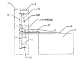
X線CT装置は、図2に示すように被検体を介して対向配置したX線源とX線検出器を備えたスキャナ1と、載置した被検体をスキャナ1の開口部に案内する患者テーブル2と、種々の表示を行う表示装置5および各種の指示や情報等を入力する操作装置6を有する操作卓3とを備えて構成されている。またスキャナ1の外周部には上方部から被検体を撮影する被検体平面画像撮影装置32と、側方部から被検体を撮影する被検体立面画像撮影装置33とからなる被検体二次元画像撮影装置が配置されている。
The best mode for carrying out the present invention will be described below with reference to the drawings.
1 and 2 are a block diagram and a perspective view showing a schematic configuration of an X-ray CT apparatus according to an embodiment of the present invention.
The X-ray CT apparatus includes a
スキャナ1は、図1に示すようにX線制御装置7によって制御されるX線管8等のX線源を有しており、X線管8から放射されたX線をコリメータ制御装置9によって制御されるコリメータ10により、例えば角錐状のX線ビームすなわちコーンビームX線として被検体17に照射し、被検体17を透過したX線をX線検出器11に入射するようにしている。このX線検出器11は、図3に示すようにチャネル方向と列方向に二次元的に配列された複数のX線検出素子18を有している。また、X線検出器11にはデータ収集装置12が接続されており、このデータ収集装置12によってX線検出器11の個々のX線検出素子の検出データを収集するようにしている。上述したX線制御装置7からデータ収集装置12までのものがスキャナ1の回転板13に搭載されており、この回転板13は、回転制御装置14によって制御される回転板駆動装置15から駆動力伝達系16を通じて伝達される駆動力によって回転される。
As shown in FIG. 1, the
上述したX線検出器11は、図3に示すように複数のX線検出素子18をチャネル方向と列方向とに二次元的に配列した構成となっている。X線検出素子18は、全体として円筒面状もしくはチャネル方向に関して折れ線状に湾曲したX線入射面を構成しており、チャネル番号iは例えば1〜1000程度、列番号jは例えば1〜1000程度である。またX線検出素子18は、例えばシンチレータとフォトダイオードの組み合わせによって構成される。X線検出器11におけるチャネルの配列方向に一致するコーンビームX線のチャネル方向の広がり角度、すなわちファン角度はαであり、またX線検出器11における列の配列方向に一致するコーンビームX線の列方向広がりの角度、すなわちコーン角度はγである。図4に示すように患者テーブル2の天板4に載せられた被検体17がスキャナ1の開口部に搬入された後、コリメータ10の開口幅によりコーン角度γを調整したコーンビームX線を被検体17に照射すると、コーンビームX線を照射された被検体17の像はX線検出器11に投影され、X線検出器11によって被検体17を透過したX線が検出される。
The
患者テーブル2は、図1に示すように患者テーブル制御装置20によって患者テーブル上下動装置21を制御して適切なテーブル高さにすると共に、患者テーブル制御装置20によって天板駆動装置22を制御して天板4を前後動させ、被検体17をスキャナ1のX線照射空間に搬入および搬出するように構成している。
As shown in FIG. 1, the patient table 2 controls the patient table
操作卓3は、図1に示すようにシステム制御装置19を有しており、このシステム制御装置19には、スキャナ1と患者テーブル2、また被検体二次元画像撮影用制御装置34を介して被検体平面画像撮影装置32および被検体立面画像撮影装置33が接続されている。システム制御装置19によってスキャナ1内のX線制御装置7、コリメータ制御装置9、データ収集装置12および回転制御装置14が制御され、また患者テーブル2内の患者テーブル制御装置20が制御される。
As shown in FIG. 1, the
システム制御装置19は、スキャナ1内のデータ収集装置12で収集されたデータを画像再構成装置23に入力し、この画像再構成装置23においてデータ収集装置12で収集した複数ビューの投影データを用いて画像を再構成する。この画像再構成装置23において再構成された画像や、各種データおよび本装置の機能を実現するためのプログラム等は、システム制御装置19に接続された記憶装置24に格納されている。またシステム制御装置19には表示装置5と操作装置6とが接続されており、画像再構成装置23から出力される再構成画像やシステム制御装置19が取り扱う種々の情報を表示装置5に表示させるように構成している。
The
システム制御装置19によって制御される被検体二次元画像撮影用制御装置34は、被検体平面画像撮影装置32および被検体立面画像撮影装置33からなる被検体二次元画像撮影装置を制御して断層像撮影位置(スキャン位置)や管電流制御条件等のスキャン条件を事前に計画するための基データとなる被検体二次元画像データを撮影する。被検体平面画像撮影装置32および被検体立面画像撮影装置33は可視光画像もしくは赤外線画像の撮影装置であり、被検体平面画像撮影装置32は例えばスキャナ室の天井に固定されて被検体17の平面像を撮影し、また被検体立面画像像撮影装置33は例えばスキャナ室の側壁に固定されて被検体17の立面像を撮影するようにしている。これら撮影された被検体平面画像データおよび被検体立面画像データからなる被検体二次元画像データは、被検体二次元画像撮影用制御装置34を介してシステム制御装置19に渡され、さらにシステム制御装置19によって制御されるスキャン計画装置35に渡されて、スキャン条件の事前計画作成のために用いられる。
The subject two-dimensional image
また、この被検体二次元画像データは、スキャン計画装置35によって被検体仮想スキャノグラムデータ生成に用いられる。生成された被検体仮想スキャノグラムデータはシステム制御装置19によってを表示装置5に表示され、操作者は表示された被検体仮想スキャノグラムデータ上で操作装置6を用いて断層像撮影予定位置の座標を指定することにより、断層像撮影位置の計画を立てることができる。ここで計画した断層像撮影予定位置の情報は記憶装置24に保存され、スキャン計画装置35によって管電流制御条件等の計画を立てるためにも用いられる。
The subject two-dimensional image data is used by the
このスキャン計画装置35は、詳細について後述するが、操作装置6から入力された管電圧、管電流設定値、X線コリメーション条件、およびスキャン計画装置35によって算出される被検体17の三次元的CT値分布のデータを基にして、次の各項目(1)〜(4)の値を算出し表示装置5に表示する。
The
(1)スキャン中に被検体17の撮影部位の透過X線量の変化に応じて経時的に変化する一連の管電流値すなわち、管電流の変化パターン。これは推奨管電流基準値と被検体モデルから決定する。決定された管電流変化パターンは記憶装置24に保存され、本スキャン時に被検体17の撮影部位に応じて順次呼び出されて、X線管8の管電流を変化させる。
(2)推定被曝線量。これについては基準人体モデルでの実測値もしくは理論計算値をデータベース内に格納しておき、それらと被検体のモデル番号、推奨X線条件を比較して推定する。推定被曝線量は表示装置5に表示されることにより操作者に評価され、操作者は必要に応じて操作装置6を操作してX線条件の変更を行うことができる。なお、被曝線量の問題に関しては散乱線の影響が無視できないため、基準人体モデルでの被曝線量を理論計算によって求める場合は、直接線と散乱線の双方の影響を考慮した計算が必要である。
(1) A series of tube current values that change with time in accordance with changes in the transmitted X-ray dose of the imaging region of the subject 17 during a scan, that is, a change pattern of tube current. This is determined from the recommended tube current reference value and the subject model. The determined tube current change pattern is stored in the
(2) Estimated exposure dose. About this, the actual measurement value or theoretical calculation value in the reference human body model is stored in the database, and the model number of the subject and the recommended X-ray condition are compared and estimated. The estimated exposure dose is evaluated by the operator by being displayed on the
(3)推定画像ノイズ。これについては基準人体モデルでの実測値もしくは理論計算値をデータベース内に格納しておき、それらと被検体のモデル番号、推奨X線条件を比較して推定する。推定画像ノイズは表示装置5に表示されることにより操作者に評価され、操作者は必要に応じて操作装置6を操作してX線条件の変更を行うことができる。(4)被検体のモデルに対して推奨するX線管電圧。例えば、被検体モデルが通常の成人に相当する場合は管電圧として一般的な値を推奨するが、小児に相当する場合、X線管電圧として一般的な値よりも低い値を推奨し、また被検体モデルが一般的な成人にくらべて十分大きい場合にはX線管電圧として一般的な値よりも高い値を推奨する。
(3) Estimated image noise. About this, the actual measurement value or theoretical calculation value in the reference human body model is stored in the database, and the model number of the subject and the recommended X-ray condition are compared and estimated. The estimated image noise is evaluated by the operator by being displayed on the
図5は、上述したX線CT装置による断層像生成処理動作を示すフローチャートである。
先ず、被検体17の断層画像を取得する本スキャンの前に、スキャン条件を設定するために種々の準備操作を行う。この準備操作としては、被検体17の断層像撮影位置決定のための基データとなる被検体二次元画像データの撮影、管電流設定のための被検体二次元画像データの解析、スキャン条件としての管電流の変化パターンの決定などがあり、これらをシステム制御装置19の制御下で行う。
FIG. 5 is a flowchart showing the tomographic image generation processing operation by the X-ray CT apparatus described above.
First, before the main scan for acquiring a tomographic image of the subject 17, various preparation operations are performed in order to set scan conditions. As this preparatory operation, imaging of subject two-dimensional image data, which becomes basic data for determining the tomographic imaging position of the subject 17, analysis of subject two-dimensional image data for setting tube current, and scanning conditions For example, the change pattern of the tube current is determined, and these are performed under the control of the
ステップS1の被検体二次元画像撮影の工程では、被検体平面画像撮影装置32および被検体立面画像撮影装置33からなる被検体二次元画像撮影装置を用いて可視光または赤外線により被検体17の被検体二次元画像を撮影する。この被検体二次元画像データとしては、図6に示すような被検体平面画像撮影装置32によってスキャナ室天井側から見た被検体平面画像データ27aと、図7に示すような被検体立面画像撮影装置33によってスキャナ室側壁側から見た被検体立面画像データ27bが得られる。これらの被検体二次元画像データは、被検体平面画像撮影装置32および被検体立面画像撮影装置33から被検体二次元画像撮影用制御装置34、システム制御装置19を介してスキャン計画装置35に送られると共に記憶装置24に保存される。
In the step of subject two-dimensional image photographing in step S1, the subject 17 is imaged by visible light or infrared light using a subject two-dimensional image photographing device including the subject flat
これらの被検体二次元画像データは、後述するステップS2〜ステップS3でスキャン計画装置35により被検体17の被検体仮想スキャノグラムデータを作成するために利用される。この被検体仮想スキャノグラムデータは、従来技術によるX線CT装置において本スキャンの前にX線を曝射して得ていたスキャノグラム像が果たしていたものと同様の役割を果たすもので、CTスキャン時の被検体17の断層像撮影位置決定のために利用される。また後述するステップS9〜ステップS10で仮想スキャノグラムデータに基づいて作成される被検体三次元CT値モデルは、特に管電流制御のための管電流変化パターン決定のために利用される。
These subject two-dimensional image data are used to create subject virtual scanogram data of the subject 17 by the
ステップS2の被検体二次元画像データ解析の工程およびステップS3の仮想スキャノグラムデータ生成の工程では、先の被検体二次元画像データがスキャン計画装置35によって解析され、被検体仮想スキャノグラムデータが生成される。この被検体仮想スキャノグラムデータは被検体17を一定方向、例えば背面から正面へ透過するX線あるいは左側面から右側面へ透過するX線による像を、X線曝射することなく可視光または赤外線による二次元画像データから仮想的に生成したものである。
In the subject two-dimensional image data analysis step in step S2 and the virtual scanogram data generation step in step S3, the previous subject two-dimensional image data is analyzed by the
ここで、この被検体仮想スキャノグラムデータの生成法の一例について説明する。
可視光または赤外線による被検体二次元画像データが得られると、各画素位置における被検体17の仮想スキャノグラムデータを推定することができる。このX線CT装置では、予め基準とすべき複数の基準人体CT値モデルのデータを取得して記憶装置24にデータベースファイルとして格納しておき、この基準人体CT値モデルデータから算出される基準人体スキャノグラムデータを、ステップS1で取得した被検体17の被検体二次元画像データに基づいて補正することにより、被検体仮想スキャノグラムデータを作成する。上述した基準人体CT値モデルデータとしては、例えば標準的な人体ファントムなどをCT撮影した断層画像から得られる三次元的CT値分布データとその相似変換データが用いられる。断層画像はCT値の分布を表し、実効エネルギー(例えば管電圧120kVの場合、通常60keV〜70keV)のX線に対するX線吸収係数の分布を表しているので、この断層画像を三次元に再構成した三次元的CT値分布データはX線吸収係数の三次元的な空間分布のデータであり、被検体17に照射されたX線の減弱量の計算に利用することができる。
Here, an example of a method for generating the subject virtual scanogram data will be described.
When the subject two-dimensional image data using visible light or infrared light is obtained, virtual scanogram data of the subject 17 at each pixel position can be estimated. In this X-ray CT apparatus, data of a plurality of reference human CT value models to be used as references are acquired in advance and stored as database files in the
上述した基準人体CT値モデルを用いて仮想スキャノグラムデータを作成する具体例を図6を用いて説明する。
基準人体CT値モデルデータ25から基準人体正面スキャノグラムデータ26aを計算で求め、この基準人体正面スキャノグラムデータ26aと、ステップS1で被検体17を撮影して得た被検体平面画像データ27aとから被検体17の仮想正面スキャノグラムデータ36aを計算で求めている。このとき、被検体17に最も近い基準人体CT値モデルを記憶装置24に保存してあるデータベースファイル内から選択する。そのためにはステップS2の被検体二次元画像データ解析において、複数の基準人体CT値モデルデータについて各々計算で求めた基準人体正面スキャノグラムデータ26aと被検体平面画像データ27aについて、画素面積の総和を計算し、それらを比較することにより被検体17に最も近いと推定される基準人体CT値モデルを選択する。
A specific example of creating virtual scanogram data using the above-described reference human CT value model will be described with reference to FIG.
Reference human
こうして選択された基準人体CT値モデルデータ25は、人体ファントムなどの標準的な人体の体幹部のCT値分布モデルもしくはその相似変換モデルで、ここでは肩から腹部までのスライス位置ごとの断面のCT値モデルとして示している。スキャノグラムデータは、その三次元的CT値モデルから計算によって生成することができるので、基準人体正面スキャノグラムデータ26aは基準人体CT値モデルデータ25について背面方向から投影したデータを求めることによって得られる。また被検体平面画像データ27aは、被検体17の体幹部について基準人体正面スキャノグラムデータ26aと同じ領域を正面方向から可視光または赤外線で撮影した被検体二次元画像データである。
The reference human CT
体幹部の基準人体正面スキャノグラムデータ26aと被検体平面画像データ27aとを並置して対比できるように示してあるが、一般的に両者は寸法が異なる。そこで、基準人体スキャノグラムデータ26aと被検体平面画像データ27aとを対比しながら、両者の差異に基づいて一致する部分はそのままとし、異なる部分については変形させて被検体17に合うように基準人体CT値モデルデータ25を補正して、被検体仮想正面スキャノグラムデータ36aを生成する。
Although the reference human
図6に示した体幹部の例では、先ず、体軸方向に関して基準人体正面スキャノグラムデータ26aと被検体平面画像データ27aの肩からウエストまでの長さAの差異を基に、基準人体正面スキャノグラムデータ26aを補間、伸長したり、あるいは間引き、短縮したりすることで、基準人体正面スキャノグラムデータ26aの体軸方向の形状を被検体17の実状に近似させる。また左右方向に関しては、体軸を基準にして左と右に分けてそれぞれの差異を基に左右の広がりを補正し、被検体17の実状に近似させる。このようにして基準人体正面スキャノグラムデータ26aの外形を被検体平面画像データ27aに近似させ、被検体仮想正面スキャノグラムデータ36aを生成する。また図7に示すように基準人体側面スキャノグラムデータ26bと被検体立面画像データ27bを用いて、体軸方向の長さや体の前後方向の厚みを比較し、被検体仮想側面スキャノグラムデータ36bを生成する。
In the example of the trunk shown in FIG. 6, first, based on the difference in the length A from the shoulder to the waist of the reference human
このように基準人体CT値モデルデータ25を記憶装置24内に格納し、この基準人体CT値モデルデータ25による基準人体スキャノグラム26a,26bと、被検体二次元画像撮影装置32,33による被検体二次元撮影データ27a,27bとから被検体仮想スキャノグラムデータ36a,36bを算出する算出手段を有してスキャン計画装置35を構成したため、本スキャン前に被検体17にX線を曝射することなく被検体仮想スキャノグラムデータ36a,36bを得ることができ、しかも、この被検体仮想スキャノグラムデータ36a,36bは、従来のように本スキャンに先立って被検体17にX線を曝射して得たスキャノグラムデータに替えて利用することができる。
In this way, the reference human CT
ステップS4からステップS6の工程では、操作者が被検体仮想スキャノグラムデータ36a,36bを参照しながら操作装置6からスキャン条件としての天板移動ピッチや、スキャン開始位置およびスキャン終了位置を入力する。これらの情報により、被検体17のスキャン範囲と、断層像撮影位置(スライス位置)zと、X線管8の位相角つまり回転板13の位相角βが決定される。続くステップS7およびステップS8の工程では、操作者が操作装置6からスキャン条件としての管電圧設定値、最大管電流設定値を入力する。
In steps S4 to S6, the operator inputs the top board movement pitch, the scan start position, and the scan end position as scan conditions from the
次に、ステップS9の仮想スキャノグラムデータ解析工程およびステップS10の被検体三次元CT値モデル生成工程では、被検体仮想スキャノグラムデータ36a,36bがスキャン計画装置35によって解析され、被検体三次元CT値モデルすなわち被検体17の三次元的CT値モデルが生成される。この被検体CT値分布モデルは、被検体17をCT撮影する場合の被検体17の位置とCT値分布との関係を示すモデルである。被検体三次元CT値モデルの作成方法については特開2002−263097号公報にも同様の方法が開示されているが、本実施の形態においては基準とすべき人体CT値モデルを複数用意しておくことにより、被検体三次元CT値モデルを生成するための近似計算の精度を高めている。ただし、基準モデルの選択の余地がないことによる近似精度の若干の低下を別にすれば、基準とすべき人体CT値分布モデルが単数であっても良い。
Next, in the virtual scanogram data analysis step in step S9 and the subject three-dimensional CT value model generation step in step S10, the subject
次に、ステップS10における被検体三次元CT値モデルの作成方法について図8を用いて説明する。
既に、被検体仮想スキャノグラムデータ36a,36bはステップS3で得られ、ステップS4〜ステップS6の工程でスキャン範囲と断層像撮影位置が指定されているので、各断層像撮影位置における被検体17のCT値モデルを推定することができる。すなわち、各断層像撮影位置における被検体17の幅は被検体仮想正面スキャノグラムデータ36aにおいて推定されているので、基準人体CT値モデルデータ25の各断層像撮影位置における幅が被検体仮想正面スキャノグラムデータ36aの各断層像撮影位置における幅と一致するよう補間拡大、補間縮小等を行って近似する。また各断層像撮影位置における被検体17の前後方向、例えば、ここでは腹側を前、背側を後とするとその厚さは被検体仮想立面スキャノグラムデータ36bにおいて推定されているので、基準人体CT値モデルデータ25の各断層像撮影位置における厚さが被検体仮想正面スキャノグラムデータ36bの各断層像撮影位置における厚さと一致するよう補間拡大、補間縮小等を行って近似する。このようにして、2つの被検体仮想スキャノグラムデータ36a,36bを基に、基準人体CT値モデルデータ25を実際の被検体17に近似させ被検体三次元CT値モデルデータ28を生成する。なお、CT値HとX線吸収係数μとの間には数1に示す関係があるので、被検体三次元CT値モデルデータ28が生成されれば被検体17におけるX線吸収係数の分布は数1を用いて容易に計算できる。
![]()
The subject
![]()
次に、ステップS11の工程では、各スライス位置z、X線管8の位相角β毎のX線減弱指数を算出する。ここでX線減弱指数はX線透過経路に沿ったX線吸収係数分布の積分値である。このデータは被検体三次元CT値モデルデータ28から求めることができるので、スキャン計画装置35が記憶装置24から被検体三次元CT値モデルデータ28を呼び出して演算する。このX線減弱指数演算結果Tは、T=T(z,β)で表される。
Next, in step S11, an X-ray attenuation index is calculated for each slice position z and for each phase angle β of the
次に、ステップS12の工程では、スキャン条件としてのスキャン時間を操作装置6より入力する。スキャン開始位置と、天板移動ピッチと、スキャン時間が決定すると、スキャン中のX線管8の位置(z,β)はスキャン開始後の経過時間tの関数として表すことができるので、各スキャン位置での被検体17のX線減弱指数Tも時間tの関数T=T(t)として表すことができる。このため、ステップS13の工程では、X線減弱指数Tの関数をT=T(z,β)からT=T(t)に変換する。
Next, in the process of step S <b> 12, a scan time as a scan condition is input from the
次に、ステップS14における管電流の設定方法について説明する。
先ず、被検体17をスキャンする全範囲におけるX線減弱指数の最大値つまり全スライス位置P1 〜Pn の中でのX線減弱指数の最大値をTmax、同じくX線減弱指数の最小値をTminとする。これらの値は被検体三次元CT値モデルデータ28を作るとき既知である。管電流を最大値Imax(mA)と最小値Imin(mA)の範囲で変化させる場合、ここでは管電流の最大値、最小値とパスの最大値、最小値をそれぞれ対応させて、管電流とパスとの間に適切な関係を持たせるものである。また管電流の最小値Imin(mA)はX線制御装置7およびX線管8の性能に基づいて最大値Imax(mA)から精度良く制御可能な電流値幅Iw(mA)を考慮して数2の如く決定される。
![]()
First, the maximum value of the X-ray attenuation index in the entire range in which the subject 17 is scanned, that is, the maximum value of the X-ray attenuation index in all slice positions P1 to Pn is Tmax, and the minimum value of the X-ray attenuation index is Tmin. To do. These values are known when the object three-dimensional CT
![]()
X線管電流IとパスTとの関係は数3の如く表される。

The relationship between the X-ray tube current I and the path T is expressed as
ここで、パスTはステップS12により一連のスキャン開始後の経過時間tの関数であるので、X線管電流Iも経過時間tの関数となる。このように決定されたX線管電流の変化パターンI=I(t)を記憶装置24に保存し、本スキャン時に被検体17の撮影部位に応じてシステム制御装置19によって順次呼び出してX線制御装置7を介してスキャン中の管電流を制御する。
Here, since the path T is a function of the elapsed time t after the start of a series of scans in step S12, the X-ray tube current I is also a function of the elapsed time t. The X-ray tube current change pattern I = I (t) determined in this way is stored in the
次に、ステップS15およびステップS16による推定被曝線量の算出と表示について説明する。この説明に入る前に被検体17内の推定被曝線量分布の計算結果の表示例を図9に示す。同図には被検体17内の被曝線量分布の等しい等被曝線量線29a〜29cが例示されており、体表に近いほど高被曝線量になっている。被曝線量分布の推定は三次元的に行われるので、推定被曝線量の分布表示は被検体17の横断面に限らず、例えば被検体17の体軸に沿った鉛直面、水平面等での推定被曝線量分布を表示することも可能である。また等被曝線量線を表示するだけでなく、各断層像の断層面内平均被曝線量や一連のスキャンの総合的な被曝結果としての総被曝43も表示することができる。ここでは、被検体17の被曝線量分布が表示装置5によって操作者に提示されるため、操作者は被検体17のX線被曝についてより詳細な評価を行うことができる。
Next, calculation and display of the estimated exposure dose in step S15 and step S16 will be described. Before entering this description, a display example of the calculation result of the estimated dose distribution in the subject 17 is shown in FIG. In the figure,
さて、ステップS15で被検体内の被曝線量分布を計算するために、予め記憶装置24に保存してあるデータベースファイルには基準人体CT値モデル25に対する被曝線量分布の実測値もしくは理論計算値を格納している。すなわち、使用可能な各X線管電圧毎、各基準人体CT値モデル毎、各横断面毎に、代表的なX線管電流パラメータを用いて複数の適当な測定点における被曝線量を測定しておき、もしくは理論計算しておき、記憶装置24に保存されているデータベースファイルに記録している。測定点以外の任意の位置での被曝線量は、測定点での値に基づいて補間によって求めることができるので、測定点の位置と測定点での被曝線量をデータベースファイルに記録しておけばよい。被曝線量の測定点30は、図11に示すように被検体17の横断面の重心と表層部、被検体17の主な臓器の重心と境界部というように設定する。
Now, in order to calculate the dose distribution in the subject in step S15, the measured value or the theoretical calculation value of the dose distribution for the reference human
基準人体CT値モデル25における上述の被曝線量分布データと被検体17に対する被検体三次元CT値モデル28とを用いて、基準人体CT値モデル25における被曝線量分布に対応する被検体17での被曝線量分布、各横断面における断層面内平均被曝線量、被曝線量のスライス方向積分である総被曝、などを被検体三次元CT値モデル28上で推定することができる。なお、断層面内平均被曝線量としては必要に応じて単純平均値や、体表側を重視した荷重平均値や、臓器による感受性を考慮した荷重平均値等を選択して使用することができる。
Using the above-mentioned exposure dose distribution data in the reference human
次に、ステップS16の推定被曝線量表示の工程では、ステップS15の計算結果を表示装置5に表示する。この表示例としては、図9に示したような被検体17の断層面内の被曝線量分布、図10に示した被検体17の断層面内平均被曝線量のz方向分布41、および断層面内平均被曝線量のz方向積分値としての総被曝42などを用いることができる。図9では、被検体17の臓器と被曝線量分布を示す等被曝線量線を重ねて表示しているので、各臓器への被曝線量を認識することが容易であるし、図10では各断層位置での断層面内平均被曝線量がスライス位置zに応じてどのように変化しているかを容易に認識できると共に、その積分値としての総被曝が表示されるので、被検体17へのX線被曝を評価する上で有効である。また図示を省略しているが、被検体17の体軸に沿った鉛直断面、水平断面等における被曝線量分布も表示可能である。
Next, in the step of displaying the estimated dose in step S16, the calculation result in step S15 is displayed on the
またステップS17およびステップS18の工程において、被検体17の断層像における推定画像ノイズを算出し表示する。この目的のため、記憶装置24に予め保存してあるデータベースファイルには、使用可能な各管電圧、各基準人体CT値モデル、代表的な管電流パラメータを用いた場合の画像ノイズの測定値もしくは理論計算値を格納してある。スキャン計画装置35は、ステップS10の工程で求めた被検体三次元CT値モデルと記憶装置24から読み出したデータベースファイル内の各基準人体CT値モデルを比較することにより、被検体17における画像ノイズを推定し表示させる。すなわち、図12に示すように被検体三次元CT値モデル28の断面積と、基準人体CT値モデル25の断面積−画像ノイズ曲線37とから被検体17の各断層位置における画像ノイズを推定し、図13のように表示装置6に推定画像ノイズ38を表示する。また推定画像ノイズ38だけでなく、ステップS13で推定した断層面内平均被曝線量推定値39や推定総被曝40も表示することができ、画像ノイズと被曝線量のバランスが適正であるかどうかを容易に判断することが可能である。
Further, in step S17 and step S18, the estimated image noise in the tomographic image of the subject 17 is calculated and displayed. For this purpose, the database file stored in advance in the
次に、ステップS19の被曝線量・画像ノイズ判断の工程では、ステップS16で表示された被検体17の推定被曝線量計算結果と、ステップS18で表示された被検体17の推定画像ノイズ計算結果とを操作者が見て、被曝線量と画質のバランスが適正であるかどうかを判断し、適正であると判断した場合にはステップS20のスキャン実行の工程に進んでスキャンを開始することになる。一方、適正でないと判断した場合にはステップS21により管電流パターンの編集後、ステップS22の管電圧設定値の再入力、あるいはステップS8の最大管電流設定値の再入力を選択し実行する。 Next, in the exposure dose / image noise determination process in step S19, the estimated exposure dose calculation result of the subject 17 displayed in step S16 and the estimated image noise calculation result of the subject 17 displayed in step S18 are obtained. The operator determines whether or not the balance between the exposure dose and the image quality is appropriate, and if it is determined to be appropriate, the process proceeds to the scan execution step of step S20 to start scanning. On the other hand, if it is determined that it is not appropriate, after editing the tube current pattern in step S21, re-input of the tube voltage set value in step S22 or re-input of the maximum tube current set value in step S8 is selected and executed.
また、ステップS10での被検体17のCT値モデルデータの生成方法としては、前述の基準人体CT値モデルデータ25を使う方法以外に、過去に撮影した同じ被検体17のCT撮影データを使用する方法も実施可能である。この場合には、実際に同一の被検体17のCT値分布データを使用するために、基準人体CT値モデルデータ25の形状を補正する手順が必要なくなるという利点がある。しかし初回のCT撮影には使用できないため、過去にCT撮影を行った被検体17に関して、2回目以降のCT撮影を行う場合が対象となる。また被検体17内で実際の被曝線量を測定することは現実的ではないため、データベースに格納しておく被曝線量データとしては被検体17のCT値分布に対する被曝線量理論計算値を用いる。
Further, as a method of generating CT value model data of the subject 17 in step S10, CT imaging data of the
このようにCTスキャン前に被検体17の体内の被曝線量分布と画像ノイズを推定して、推定結果を図13に示す如く推定画像ノイズ38および平均被曝線量推定値39として表示することにより、操作者は事前に撮影手技に応じた被検体17の被曝線量分布と画像ノイズを近似的に知ることが可能となる。この結果、例えば、単純に被検体17の全ての組織に関して一律に被曝線量を減らすのではなく、骨髄や肺等の放射線感受性の高い組織に関しては特に被曝線量を低減し、逆に脂肪や筋肉等の放射線感受性の比較的低い組織には、画質が満足できる程度に被曝線量のレベルを維持するというような詳細な設定が可能となる。ステップS23における管電流パターンの編集工程はこのために必要な工程である。
In this way, the dose distribution and the image noise in the body of the subject 17 are estimated before the CT scan, and the estimation result is displayed as the
次に、図14を用いて被検体17をCT撮影する管電流の変化パターンの編集について説明する。
同図は、管電流の変化パターンを被検体17の被検体仮想正面スキャノグラムデータ36aと対応させて表示したものであり、簡単化のためにX線管位相角βの変化に伴う大略周期的なX線管電流の変化については省略し、スライス位置zによる変化のみ示している。被検体仮想正面スキャノグラムデータ36aは体幹部のものを示し、管電流の変化パターンとしては、編集前の初期のX線管電流の変化パターン31aと、編集後の修正されたX線管電流の変化パターン31bとを示している。
Next, editing of the tube current change pattern for CT imaging of the subject 17 will be described with reference to FIG.
This figure shows the change pattern of the tube current in correspondence with the subject virtual
このX線管電流の変化パターンの編集工程では、表示装置5の画面において被検体仮想正面スキャノグラムデータ36a上に表示された初期設定の管電流の変化パターン31aに対し、被検体仮想正面スキャノグラムデータ36aを参照しながら、また場合によっては被検体17の内部の被曝線量分布や画像ノイズ分布を参照して操作装置6によって修正を加えて、新しい管電流の変化パターン31bを編集する。この編集操作によって任意の部位の管電流の変化パターンを再設定する。なお、被検体仮想正面スキャノグラムデータ36aの代わりに被検体仮想側面スキャノグラムデータ36bを用いても同様にX線管電流の変化パターンを編集可能である。
In the X-ray tube current change pattern editing step, the subject virtual front scan pattern is compared with the initial tube
この編集操作において、自動的な管電流の変化パターンの設定では、横隔膜付近のように密度が大きく変化する領域では、管電流を平均的な値に設定するが、被曝線量が増えても画質を向上させる必要がある領域などでは管電流を部分的に高く設定する。管電流の変化パターンは、前述の如くスキャン条件が設定されていれば、時間tのみの関数になるので、任意時刻のX線管電流の値を変化させることができる。図14に示した例では、初期の管電流の変化パターン31aに対し、肺の領域の管電流を少し低下させ、横隔膜から肝臓の領域の管電流を少し増加させることで、修正後の管電流の変化パターン31bに編集している。
In this editing operation, the automatic tube current change pattern setting sets the tube current to an average value in areas where the density changes greatly, such as near the diaphragm. In areas that need to be improved, the tube current is set to be partially high. Since the change pattern of the tube current is a function of only the time t if the scan condition is set as described above, the value of the X-ray tube current at an arbitrary time can be changed. In the example shown in FIG. 14, the tube current in the lung region is slightly reduced and the tube current in the region from the diaphragm to the liver is slightly increased with respect to the initial tube
次に管電圧の推奨に関する機能について説明する。
小児においては一般的な管電圧、例えば120kVよりも低い管電圧である80kVあるいは100kVを用いる方が画質と被曝線量のバランスが良い場合がある。そこで、被検体17が小児であることを操作者が操作装置6から予め入力した場合や、ステップS10において生成された被検体三次元CT値モデル28が小児相当のものである場合には、スキャン計画装置35は表示装置5にステップS19における判断材料として80kVあるいは100kV等の管電圧を推奨表示する。逆に一般的な成人よりも体格の大きな被検体17の場合には、一般的な管電圧120kVよりも高い管電圧である130kVあるいは140kVを用いる方が画質と被曝線量のバランスが良い場合がある。そこで、たとえばステップS10において生成された被検体三次元CT値モデル28が大被検体相当のものである場合には、スキャン計画装置35は表示装置5に、ステップS19における判断材料として130kVあるいは140kV等の管電圧を推奨表示する。またこのように推奨管電圧を表示する場合、操作者が入力した管電圧設定値に基づく推定被曝線量、推定画像ノイズのみならず、スキャン計画装置35が推奨する管電圧に基づく推定被曝線量、推定画像ノイズをも表示することにより、管電圧の選択に関する判断を容易に行うことができる。
Next, functions related to tube voltage recommendation will be described.
In children, there is a case where the balance between image quality and exposure dose is better when a general tube voltage, for example, 80 kV or 100 kV, which is a tube voltage lower than 120 kV, is used. Therefore, when the operator inputs in advance from the
このように上述したX線CT装置は、従来のように本スキャンに先立って被検体17へX線を曝射してスキャノグラムデータを得るのではなく、記憶装置24内に格納した基準人体CT値モデルデータ25による基準人体スキャノグラムデータ26a,26bを、被検体二次元画像撮影装置32,33による被検体17の二次元画像データ27a,27bに基づいて補正して従来のスキャノグラムデータに対応する被検体仮想スキャノグラムデータ36a,36bを得るようにしたため、被検体17の被曝を最小限に抑えながら、被検体仮想スキャノグラムデータ36a,36bを用いて種々のスキャン条件の設定を行うことが可能になる。
As described above, the X-ray CT apparatus described above does not obtain scanogram data by irradiating the subject 17 with X-rays prior to the main scan as in the prior art, but stores the reference human body stored in the
また上述したスキャン条件として、被検体仮想スキャノグラムデータ36a,36bを用いて断層像撮影位置の設定を行うようにすると、本スキャン前における被検体17の被曝を無くしながらも正確なスキャン位置を設定することができる。またスキャン条件として、被検体仮想スキャノグラムデータ36a,36bを用いて管電流変化パターンや管電圧の設定を行うようにすると、本スキャン前の被検体17の被曝を無くしながらも望ましい管電流変化パターンや管電圧値を設定することができる。
If the tomographic imaging position is set using the subject
図15は、本発明にさらに他の実施の形態によるX線CT装置による断層像生成処理動作を示すフローチャートである。
ここでは先の実施の形態との相違点についてのみ説明して、同等の工程については同一符号を付けて詳細な説明を省略する。ステップS6までの断層像撮影位置および断層像撮影範囲の設定後に、ステップS24の画像ノイズ上限値入力の工程を加えている。この工程の追加によって、撮影範囲内において被曝線量に配慮しつつ一定レベル以上の画質を確保するために操作者が予め画像ノイズ上限値を入力することができるようにしている。また同じく操作者が入力したX線条件からスキャン計画装置35により推定された画像ノイズとの比較により、スキャン計画装置35が必要と判断するX線条件としてステップS25で最大管電流推奨値を算出し、この算出した最大管電流推奨値をステップS26として表示装置5に表示するようにしたもので、一層適正なCT検査の実行が可能になる。
FIG. 15 is a flowchart showing a tomographic image generation processing operation by an X-ray CT apparatus according to still another embodiment of the present invention.
Here, only differences from the previous embodiment will be described, and the same steps will be denoted by the same reference numerals and detailed description thereof will be omitted. After setting the tomographic imaging position and tomographic imaging range up to step S6, the step of inputting the image noise upper limit value in step S24 is added. By adding this process, an operator can input an image noise upper limit value in advance in order to ensure an image quality of a certain level or more while taking into account the exposure dose within the imaging range. Similarly, the recommended maximum tube current value is calculated in step S25 as an X-ray condition that the
図16は、本発明にさらに他の実施の形態によるX線CT装置による断層像生成処理動作を示すフローチャートである。
ここでは図5に示した実施の形態との相違点についてのみ説明して、同等の工程については同一符号を付けて詳細な説明を省略する。ステップS6までの断層像撮影位置の設定後に、ステップS27の被曝線量上限値入力の工程を加えている。この工程の追加によって、撮影範囲内において画質に配慮しつつ一定レベル以下の被曝線量とするために操作者が予め被曝線量上限値を入力することができる。また同じく操作者が入力したX線条件からスキャン計画装置35により推定された被曝線量との比較により、スキャン計画装置35が必要と判断するX線条件としてステップS25で最大管電流推奨値を算出し、この算出した最大管電流推奨値をステップS26として表示装置5に表示するようにしたもので、一層適正なCT検査の実行が可能になる。
FIG. 16 is a flowchart showing a tomographic image generation processing operation by an X-ray CT apparatus according to still another embodiment of the present invention.
Here, only differences from the embodiment shown in FIG. 5 will be described, and the same steps will be denoted by the same reference numerals and detailed description thereof will be omitted. After the setting of the tomographic imaging position up to step S6, the step of inputting the exposure dose upper limit value in step S27 is added. By adding this process, the operator can input an upper limit of the exposure dose in advance in order to obtain an exposure dose below a certain level while taking image quality into consideration within the imaging range. Similarly, the recommended maximum tube current value is calculated in step S25 as an X-ray condition that the
図17は、本発明にさらに他の実施の形態によるX線CT装置による断層像生成処理動作を示すフローチャートである。
ここでは図5に示した実施の形態との相違点についてのみ説明して、同等の工程については同一符号を付けて詳細な説明を省略する。ステップS6までの断層像撮影位置の設定後に、ステップS28の優先項目選択判定の工程を加えている。このステップS28によって、被曝線量抑制を優先すべきか画像ノイズ抑制を優先すべきかを判定し、その結果、被曝線量抑制を優先すべき場合はステップS27の被曝線量上限値入力を行い、一方、画像ノイズ抑制を優先すべき場合はステップS24で画像ノイズ上限値入力を行う。これらステップS28、ステップS24およびステップS27の追加によって、撮影範囲内において被曝線量に配慮しつつ一定レベル以上の画質を確保するために操作者が何を優先すべきかを反映させることができ、これに応じてスキャン計画装置35で機能選択を行うことができる。
FIG. 17 is a flowchart showing a tomographic image generation processing operation by an X-ray CT apparatus according to still another embodiment of the present invention.
Here, only differences from the embodiment shown in FIG. 5 will be described, and the same steps will be denoted by the same reference numerals and detailed description thereof will be omitted. After the setting of the tomographic imaging position up to step S6, the priority item selection determination step of step S28 is added. In this step S28, it is determined whether priority should be given to dose reduction or image noise suppression. As a result, if priority should be given to dose reduction, the dose upper limit value input in step S27 is performed. If suppression should be given priority, an image noise upper limit value is input in step S24. By adding these step S28, step S24, and step S27, it is possible to reflect what the operator should prioritize in order to ensure an image quality of a certain level or more in consideration of the exposure dose within the imaging range. Accordingly, the function can be selected by the
上述したX線CT装置は、被検体17の三次元的基準人体CT値モデルデータ25と、被検体17の二次元画像を撮影する二次元画像撮影装置32,33と、この二次元画像撮影装置32,33で撮影した被検体二次元画像データ27a,27bと三次元的基準人体CT値モデルデータ25から計算した基準人体スキャノグラム26a,26bとに基づいて被検体仮想スキャノグラムデータ36a,36bを得て、この被検体仮想スキャノグラムデータ36a,36bから被検体の断層像撮影位置を事前に計画すると共に、三次元的基準人体CT値モデルデータ25と被検体仮想スキャノグラムデータ36a,36bから被検体三次元CT値モデルデータ28を算出し、この被検体三次元CT値モデルデータ28に基づいて推定断層画像ノイズ、推定平均被曝線量、推定総被曝、推定被曝線量分布、部位やスキャナ回転位相に対応した推奨X線管電流変化パターン、推奨X線管電圧などの推定項目および推奨項目を算出して表示装置6に表示するスキャン計画装置35と、これら推定項目および推奨項目に関連したスキャン条件を入力する操作装置6と、この操作装置6から入力したスキャン条件に従ってX線を制御するシステム制御装置19を備えているため、従来のように本スキャンの前に被検体17にX線を曝射してスキャノグラムを撮影することなく被検体仮想スキャノグラムデータ36a,36bを利用することができ、この被検体仮想スキャノグラムデータ36a,36bから被検体の断層像撮影位置を指定したり、断層撮影像の画質と被曝線量とのバランスを適正化する推奨スキャン条件を操作者に提供することができる。
The X-ray CT apparatus described above includes the three-dimensional reference human CT
1 スキャナ
2 患者テーブル
3 操作卓
5 表示装置
6 操作装置
8 X線管
11 X線検出器
17 被検体
19 システム制御装置
23 画像再構成装置
24 記憶装置
25 基準人体CT値モデルデータ
26a 基準人体正面スキャノグラムデータ
26b 基準人体側面スキャノグラムデータ
27a 被検体平面画像データ
27b 被検体立面画像データ
28 被検体三次元CT値モデルデータ
29a〜29c 等被曝線量線
30 被曝線量測定点
31a,31b 管電流変化パターン
32 被検体二次元平面画像撮影装置
33 被検体二次元立面画像撮影装置
34 被検体二次元画像撮影用制御装置
35 スキャン計画装置
36a 被検体仮想正面スキャノグラムデータ
36b 被検体仮想側面スキャノグラムデータ
DESCRIPTION OF
Claims (1)
基準被検体の三次元的基準被検体CT値モデルデータを格納した記憶装置と、
可視光もしくは赤外線により対象とする被検体の二次元画像を撮影する被検体二次元画像撮影装置と、
前記三次元的基準被検体CT値モデルデータから算出した基準被検体スキャノグラムデータと前記被検体二次元画像撮影装置で撮影した被検体の前記被検体二次元画像データとに基づいて被検体仮想スキャノグラムデータを得て、この被検体仮想スキャノグラムデータから対象とする被検体の断層像撮影位置および断層像撮影範囲を本スキャン前に計画すると共に、三次元的基準被検体CT値モデルデータと被検体仮想スキャノグラムデータから三次元的被検体CT値モデルを算出し、この三次元的被検体CT値モデルに基づいて推定断層画像ノイズ、推定平均被曝線量、推定総被曝、推定被曝線量分布、部位やスキャナ回転位相に対応した推奨X線管電流変化パターン、推奨X線管電圧などの推定項目および推奨項目を算出して前記表示装置に表示するスキャン計画装置と、
を備え、
上記スキャン計画装置の上記基準被検体スキャノグラムデータは、上記被検体二次元画像撮影装置で撮影した被検体二次元画像データの面積と、該被検体二次元画像データと同じ方向から撮影したものと仮定し基準被検体CT値モデルから算出される基準被検体スキャノグラムデータの面積を比較し、基準被検体スキャノグラムデータの面積が該被検体二次元画像の面積に最も近い基準被検体CT値モデルを選択して得たものとし、
更に、上記スキャン計画装置での上記被検体仮想スキャノグラムデータは、この得られた基準被検体スキャノグラムデータと上記被検体二次元画像撮影装置で撮影した被検体二次元画像データとの寸法・形状を比較して、撮影した被検体二次元画像データの寸法・形状になるように基準被検体スキャノグラムデータの寸法・形状を補正して得るものとした、X線CT装置。 An X-ray source that emits X-rays while rotating around the subject, and an X-ray detection that detects an X-ray amount that is disposed opposite to the X-ray source and that passes through the subject. , An operation means for inputting imaging conditions, and an image for reconstructing a tomographic image based on transmitted X-ray data exposed from the X-ray source and detected by the X-ray detector according to the input imaging conditions In an X-ray CT apparatus comprising a reconstruction device and a display device that displays a tomographic image reconstructed by the image reconstruction device,
A storage device storing three-dimensional reference object CT value model data of the reference object;
A subject two-dimensional image capturing device that captures a two-dimensional image of the target subject with visible light or infrared;
Based on the reference object scanogram data calculated from the three-dimensional reference object CT value model data and the object two-dimensional image data of the object photographed by the object two-dimensional image photographing device Scanogram data is obtained, and the tomographic imaging position and tomographic imaging range of the target subject are planned from this subject virtual scanogram data before the main scan, and a three-dimensional reference subject CT value model 3D object CT value model is calculated from data and object virtual scanogram data, and estimated tomographic image noise, estimated average exposure dose, estimated total exposure, estimated exposure based on this 3D object CT value model The estimated and recommended items such as the recommended X-ray tube current change pattern and the recommended X-ray tube voltage corresponding to the dose distribution, region and scanner rotation phase are calculated and the display device is calculated. And the scan planning device to be displayed in,
With
The reference subject scanogram data of the scan planning device is an image of the area of the subject two-dimensional image data photographed by the subject two-dimensional image photographing device, and photographed from the same direction as the subject two-dimensional image data. And comparing the areas of the reference object scanogram data calculated from the reference object CT value model, and the area of the reference object scanogram data is closest to the area of the two-dimensional image of the object Suppose that it was obtained by selecting a CT value model,
Further, the subject virtual scanogram data in the scan planning device is the size of the obtained reference subject scanogram data and the subject two-dimensional image data photographed by the subject two-dimensional image photographing device. An X-ray CT apparatus which is obtained by comparing the shape and correcting the size and shape of the reference subject scanogram data so as to be the size and shape of the photographed subject two-dimensional image data .
Priority Applications (1)
| Application Number | Priority Date | Filing Date | Title |
|---|---|---|---|
| JP2003387704A JP4554185B2 (en) | 2003-11-18 | 2003-11-18 | X-ray CT system |
Applications Claiming Priority (1)
| Application Number | Priority Date | Filing Date | Title |
|---|---|---|---|
| JP2003387704A JP4554185B2 (en) | 2003-11-18 | 2003-11-18 | X-ray CT system |
Publications (3)
| Publication Number | Publication Date |
|---|---|
| JP2005143948A JP2005143948A (en) | 2005-06-09 |
| JP2005143948A5 JP2005143948A5 (en) | 2006-12-28 |
| JP4554185B2 true JP4554185B2 (en) | 2010-09-29 |
Family
ID=34694985
Family Applications (1)
| Application Number | Title | Priority Date | Filing Date |
|---|---|---|---|
| JP2003387704A Expired - Fee Related JP4554185B2 (en) | 2003-11-18 | 2003-11-18 | X-ray CT system |
Country Status (1)
| Country | Link |
|---|---|
| JP (1) | JP4554185B2 (en) |
Families Citing this family (14)
| Publication number | Priority date | Publication date | Assignee | Title |
|---|---|---|---|---|
| JP2007054372A (en) * | 2005-08-25 | 2007-03-08 | Ge Medical Systems Global Technology Co Llc | X-ray ct apparatus |
| JP2007097909A (en) * | 2005-10-05 | 2007-04-19 | Bio Arts:Kk | Radiation exposure dose control system and storage medium |
| JP2007181623A (en) * | 2006-01-10 | 2007-07-19 | Ge Medical Systems Global Technology Co Llc | X-ray ct apparatus |
| JP2008113960A (en) * | 2006-11-07 | 2008-05-22 | Ge Medical Systems Global Technology Co Llc | Radiographic apparatus |
| JP5345947B2 (en) * | 2006-12-22 | 2013-11-20 | コーニンクレッカ フィリップス エヌ ヴェ | Imaging system and imaging method for imaging an object |
| JP4729519B2 (en) * | 2007-03-09 | 2011-07-20 | ゼネラル・エレクトリック・カンパニイ | Radiation imaging method and system with organ-based radiation profile settings |
| JP2009213905A (en) * | 2009-05-18 | 2009-09-24 | Bio-Visiq Japan Inc | Radiation exposure dose control system and storage medium |
| RU2558519C2 (en) | 2009-10-22 | 2015-08-10 | Конинклейке Филипс Электроникс Н.В. | Device for collection protocol assessment |
| JP5863250B2 (en) * | 2011-01-31 | 2016-02-16 | ジーイー・メディカル・システムズ・グローバル・テクノロジー・カンパニー・エルエルシー | X-ray CT system |
| JP6342437B2 (en) * | 2016-02-22 | 2018-06-13 | ゼネラル・エレクトリック・カンパニイ | Radiation tomography system and control program therefor |
| WO2017213150A1 (en) | 2016-06-06 | 2017-12-14 | 東芝メディカルシステムズ株式会社 | X-ray ct apparatus |
| US10702219B2 (en) * | 2017-09-15 | 2020-07-07 | General Electric Company | Methods, systems, and apparatus for determining radiation doses |
| US11207041B2 (en) | 2019-07-08 | 2021-12-28 | Canon Medical Systems Corporation | X-ray CT system and medical processing apparatus |
| WO2022233704A1 (en) * | 2021-05-05 | 2022-11-10 | Koninklijke Philips N.V. | Systems and methods for processing and visualizing tube current modulations in medical imaging devices |
Citations (6)
| Publication number | Priority date | Publication date | Assignee | Title |
|---|---|---|---|---|
| JP2000152924A (en) * | 1998-11-20 | 2000-06-06 | Toshiba Corp | X-ray diagnostic device |
| JP2001178713A (en) * | 1999-12-27 | 2001-07-03 | Ge Yokogawa Medical Systems Ltd | X-ray ct system, operation console, control method therefor and storage medium |
| JP2002263097A (en) * | 2001-03-09 | 2002-09-17 | Hitachi Medical Corp | Radiographic tomograph |
| JP2003079611A (en) * | 2001-07-04 | 2003-03-18 | Toshiba Corp | X-ray computer tomographic diagnosing system |
| JP2003159240A (en) * | 2001-11-28 | 2003-06-03 | Toshiba Corp | X-ray diagnostic equipment and method for setting lighting field automatically |
| JP2003230556A (en) * | 2002-02-12 | 2003-08-19 | Toshiba Medical System Co Ltd | X-ray diagnostic equipment |
-
2003
- 2003-11-18 JP JP2003387704A patent/JP4554185B2/en not_active Expired - Fee Related
Patent Citations (6)
| Publication number | Priority date | Publication date | Assignee | Title |
|---|---|---|---|---|
| JP2000152924A (en) * | 1998-11-20 | 2000-06-06 | Toshiba Corp | X-ray diagnostic device |
| JP2001178713A (en) * | 1999-12-27 | 2001-07-03 | Ge Yokogawa Medical Systems Ltd | X-ray ct system, operation console, control method therefor and storage medium |
| JP2002263097A (en) * | 2001-03-09 | 2002-09-17 | Hitachi Medical Corp | Radiographic tomograph |
| JP2003079611A (en) * | 2001-07-04 | 2003-03-18 | Toshiba Corp | X-ray computer tomographic diagnosing system |
| JP2003159240A (en) * | 2001-11-28 | 2003-06-03 | Toshiba Corp | X-ray diagnostic equipment and method for setting lighting field automatically |
| JP2003230556A (en) * | 2002-02-12 | 2003-08-19 | Toshiba Medical System Co Ltd | X-ray diagnostic equipment |
Also Published As
| Publication number | Publication date |
|---|---|
| JP2005143948A (en) | 2005-06-09 |
Similar Documents
| Publication | Publication Date | Title |
|---|---|---|
| JP4532005B2 (en) | X-ray CT apparatus and image display method thereof | |
| JP5774447B2 (en) | X-ray CT apparatus, dose calculation method and program | |
| JP4937927B2 (en) | X-ray CT apparatus and imaging condition determination method in X-ray CT apparatus | |
| JP4822478B2 (en) | X-ray CT system | |
| JP3244458B2 (en) | X-ray tomography equipment | |
| JP5192372B2 (en) | X-ray CT system | |
| JP3124254B2 (en) | Radiation tomography equipment | |
| JP5484788B2 (en) | X-ray CT system | |
| EP2868275A1 (en) | Method and apparatus to increase the field of view in a cone-beam computerized tomography acquisition | |
| CN109561869A (en) | Method and system for computed tomography | |
| JP4554185B2 (en) | X-ray CT system | |
| US11024061B2 (en) | Apparatus and method for scattered radiation correction | |
| JP2003079611A (en) | X-ray computer tomographic diagnosing system | |
| JP4429694B2 (en) | X-ray CT system | |
| JP4159188B2 (en) | Tube current adjusting method and apparatus, and X-ray CT apparatus | |
| JP2007185358A (en) | X-ray ct system | |
| JP2004073397A (en) | X-ray ct apparatus | |
| JP5027909B2 (en) | X-ray CT system | |
| JP4887132B2 (en) | X-ray CT system | |
| JP4644292B2 (en) | X-ray CT apparatus and image display method thereof | |
| JP2006288739A (en) | X-ray ct apparatus | |
| JP2022013679A (en) | Medical image processing method, medical image processing apparatus and x-ray ct apparatus | |
| KR20110127444A (en) | Scout view acquisition method for ct | |
| JP4648355B2 (en) | Tube current adjusting method and apparatus, and X-ray CT apparatus | |
| JP5384293B2 (en) | X-ray CT system |
Legal Events
| Date | Code | Title | Description |
|---|---|---|---|
| A521 | Request for written amendment filed |
Free format text: JAPANESE INTERMEDIATE CODE: A523 Effective date: 20061115 |
|
| A621 | Written request for application examination |
Free format text: JAPANESE INTERMEDIATE CODE: A621 Effective date: 20061115 |
|
| A131 | Notification of reasons for refusal |
Free format text: JAPANESE INTERMEDIATE CODE: A131 Effective date: 20090825 |
|
| A521 | Request for written amendment filed |
Free format text: JAPANESE INTERMEDIATE CODE: A523 Effective date: 20091022 |
|
| A131 | Notification of reasons for refusal |
Free format text: JAPANESE INTERMEDIATE CODE: A131 Effective date: 20100413 |
|
| A521 | Request for written amendment filed |
Free format text: JAPANESE INTERMEDIATE CODE: A523 Effective date: 20100614 |
|
| TRDD | Decision of grant or rejection written | ||
| A01 | Written decision to grant a patent or to grant a registration (utility model) |
Free format text: JAPANESE INTERMEDIATE CODE: A01 Effective date: 20100713 |
|
| A01 | Written decision to grant a patent or to grant a registration (utility model) |
Free format text: JAPANESE INTERMEDIATE CODE: A01 |
|
| A61 | First payment of annual fees (during grant procedure) |
Free format text: JAPANESE INTERMEDIATE CODE: A61 Effective date: 20100714 |
|
| FPAY | Renewal fee payment (event date is renewal date of database) |
Free format text: PAYMENT UNTIL: 20130723 Year of fee payment: 3 |
|
| R150 | Certificate of patent or registration of utility model |
Free format text: JAPANESE INTERMEDIATE CODE: R150 |
|
| S111 | Request for change of ownership or part of ownership |
Free format text: JAPANESE INTERMEDIATE CODE: R313111 |
|
| S533 | Written request for registration of change of name |
Free format text: JAPANESE INTERMEDIATE CODE: R313533 |
|
| R350 | Written notification of registration of transfer |
Free format text: JAPANESE INTERMEDIATE CODE: R350 |
|
| LAPS | Cancellation because of no payment of annual fees |