JP4532790B2 - Color image processing method, apparatus and program - Google Patents
Color image processing method, apparatus and program Download PDFInfo
- Publication number
- JP4532790B2 JP4532790B2 JP2001226078A JP2001226078A JP4532790B2 JP 4532790 B2 JP4532790 B2 JP 4532790B2 JP 2001226078 A JP2001226078 A JP 2001226078A JP 2001226078 A JP2001226078 A JP 2001226078A JP 4532790 B2 JP4532790 B2 JP 4532790B2
- Authority
- JP
- Japan
- Prior art keywords
- color
- unit
- image
- processing
- mfp
- Prior art date
- Legal status (The legal status is an assumption and is not a legal conclusion. Google has not performed a legal analysis and makes no representation as to the accuracy of the status listed.)
- Expired - Fee Related
Links
- 238000003672 processing method Methods 0.000 title claims description 8
- 238000012545 processing Methods 0.000 claims description 70
- 238000011161 development Methods 0.000 claims description 16
- 230000010365 information processing Effects 0.000 claims 2
- 238000000034 method Methods 0.000 description 32
- 230000006870 function Effects 0.000 description 30
- 238000012937 correction Methods 0.000 description 24
- 238000010586 diagram Methods 0.000 description 21
- 230000008569 process Effects 0.000 description 17
- 238000006243 chemical reaction Methods 0.000 description 14
- 239000003086 colorant Substances 0.000 description 11
- 230000014509 gene expression Effects 0.000 description 6
- 238000012986 modification Methods 0.000 description 6
- 230000004048 modification Effects 0.000 description 6
- 239000004359 castor oil Substances 0.000 description 4
- 230000006835 compression Effects 0.000 description 4
- 238000007906 compression Methods 0.000 description 4
- 239000011159 matrix material Substances 0.000 description 4
- 238000003860 storage Methods 0.000 description 4
- 239000004065 semiconductor Substances 0.000 description 3
- 230000003595 spectral effect Effects 0.000 description 3
- 238000012546 transfer Methods 0.000 description 3
- 238000012935 Averaging Methods 0.000 description 2
- XEKOWRVHYACXOJ-UHFFFAOYSA-N Ethyl acetate Chemical compound CCOC(C)=O XEKOWRVHYACXOJ-UHFFFAOYSA-N 0.000 description 2
- 238000003705 background correction Methods 0.000 description 2
- 238000004364 calculation method Methods 0.000 description 2
- 238000004891 communication Methods 0.000 description 2
- 238000009826 distribution Methods 0.000 description 2
- 230000007613 environmental effect Effects 0.000 description 2
- 239000003292 glue Substances 0.000 description 2
- 238000005286 illumination Methods 0.000 description 2
- 230000000873 masking effect Effects 0.000 description 2
- 230000003287 optical effect Effects 0.000 description 2
- 239000004364 Benzylated hydrocarbon Substances 0.000 description 1
- 239000004358 Butane-1, 3-diol Substances 0.000 description 1
- 230000005540 biological transmission Effects 0.000 description 1
- 230000015572 biosynthetic process Effects 0.000 description 1
- 230000008859 change Effects 0.000 description 1
- 238000005520 cutting process Methods 0.000 description 1
- 230000000694 effects Effects 0.000 description 1
- 238000007429 general method Methods 0.000 description 1
- 239000011521 glass Substances 0.000 description 1
- 238000009499 grossing Methods 0.000 description 1
- 230000003993 interaction Effects 0.000 description 1
- 238000004519 manufacturing process Methods 0.000 description 1
- 230000002093 peripheral effect Effects 0.000 description 1
- 238000004080 punching Methods 0.000 description 1
- 238000009877 rendering Methods 0.000 description 1
- 230000004044 response Effects 0.000 description 1
- 238000004088 simulation Methods 0.000 description 1
- 230000002123 temporal effect Effects 0.000 description 1
- 238000012360 testing method Methods 0.000 description 1
- 230000003442 weekly effect Effects 0.000 description 1
Images


Classifications
-
- H—ELECTRICITY
- H04—ELECTRIC COMMUNICATION TECHNIQUE
- H04N—PICTORIAL COMMUNICATION, e.g. TELEVISION
- H04N1/00—Scanning, transmission or reproduction of documents or the like, e.g. facsimile transmission; Details thereof
- H04N1/46—Colour picture communication systems
- H04N1/56—Processing of colour picture signals
- H04N1/60—Colour correction or control
- H04N1/603—Colour correction or control controlled by characteristics of the picture signal generator or the picture reproducer
- H04N1/6052—Matching two or more picture signal generators or two or more picture reproducers
-
- H—ELECTRICITY
- H04—ELECTRIC COMMUNICATION TECHNIQUE
- H04N—PICTORIAL COMMUNICATION, e.g. TELEVISION
- H04N1/00—Scanning, transmission or reproduction of documents or the like, e.g. facsimile transmission; Details thereof
- H04N1/46—Colour picture communication systems
- H04N1/56—Processing of colour picture signals
- H04N1/60—Colour correction or control
- H04N1/603—Colour correction or control controlled by characteristics of the picture signal generator or the picture reproducer
Landscapes
- Engineering & Computer Science (AREA)
- Multimedia (AREA)
- Signal Processing (AREA)
- Color Image Communication Systems (AREA)
- Facsimile Image Signal Circuits (AREA)
- Image Processing (AREA)
- Color, Gradation (AREA)
- Record Information Processing For Printing (AREA)
- Facsimiles In General (AREA)
Description
【0001】
【発明の属する技術分野】
入力されたジョブを複数のカラー画像出力装置で並列処理するための画像処理を行うための画像処理方法、装置および記録媒体に関するものである。
【0002】
【従来の技術】
ユーザはそれぞれのコンピュータ上の所望のアプリケーションから、ドライバを用いて所望のプリンタを選択し、LANなどの公衆回線や専用のインターフェイスを経由して、プリントを指示している。また、サーバ、クライアント方式と呼ばれ、クライアントユーザのジョブがドキュメントサーバを経由して、プリンタに送られる方式も広く知られている。
【0003】
また、近年プリント・オン・ディマンドといわれる市場などにおいて、マニュアルや取り扱い説明書など大量ページのドキュメントや、軽印刷業界のような大量部数をプリントするケースが増えており、それを解決するために、サーバまたはクライアント内にある1つのドキュメントを複数台のプリンタに対して一斉にプリントをするというクラスタプリントの考え方が出てきている。更に、ドキュメントのカラー化も進んできたことからカラードキュメントの出力をクラスタプリントを用いて行う要求が出始めている。
【0004】
【発明が解決しようとする課題】
カラードキュメントのクラスタプリントでは、白黒ドキュメントのクラスタプリントでは問題とならなかった、各プリンタにおける出力サンプルの色味の違いが問題になってきている。すなわち、それぞれのプリンタ自身が持つ環境変動や時間的変化は、それぞれのプリンタにおけるキャリブレーションである程度は緩和されるが、複数台のプリンタ間では少なからずそれぞれ固有の特性を有しており、それらの微妙な差異が出力サンプルに現れる。ユーザにとっては同じドキュメントから作られたものにもかかわらず、一斉に出された出力サンプルの色味が異なることは時として重要な問題になってくる。同機種のプリンタ間でも色味の差が気になるが、まして異機種間のプリン間ではなおさら色味の差が気になる。
【0005】
プリンタに応じた色調整は、一般に、RIP処理と呼ばれるPDLデータをビットマップデータに変換する行程の一連の作業に組み込まれている。このため、色合わせだけを取り除くことができない。そのため、複数個のカラーMFPに出力するには、複数回のRIP処理を施さなければならず、そのために2倍のRIP時間を要するという欠点があった。
【0006】
本発明は上述の欠点に鑑みてなされたものであり、入力画像情報をビットマップ画像データに展開する処理(RIP処理)の回数を抑制し、高速に複数のカラー画像出力装置で並列処理できるようにすることを目的とする。
【0007】
また、ユーザの用途に応じて、高速な処理および高精度な処理を選択できるようにすることを目的とする。
【0008】
【課題を解決するための手段】
本願第1の発明は、入力されたジョブを複数台のカラー画像出力装置で並列処理するための画像処理方法であって、
入力画像情報をビットマップ画像データに展開する展開工程を有し、
前記展開工程は第一のモードと第二のモードを有し、
前記第一のモードは、前記入力画像情報を前記複数台のカラー画像出力装置の夫々に対応した色処理条件を用いて、複数回前記展開を行い、
前記第二のモードは、前記複数台のカラー画像出力装置に対応した色処理条件の平均値もしくは代表値もしくは中間値である色処理条件を用いて前記展開を1回行い、前記展開の結果のデータを前記複数台のカラー画像出力装置に出力することを特徴とする。
【0009】
本願第2の発明は、入力されたジョブを複数台のカラー画像出力装置で並列処理するための画像処理方法であって、
入力画像情報をビットマップ画像データに展開する展開工程を有し、
前記展開工程は第一のモードと第二のモードを有し、
前記第一のモードは、前記入力画像情報を前記複数台のカラー画像出力装置の夫々に対応した色処理条件を用いて、複数回前記展開を行い、
前記第二のモードは、前記複数台のカラー画像出力装置に対応した色処理条件に重み係数を掛けて求められた色処理条件を用いて前記展開を1回行い、前記展開の結果のデータを前記複数台のカラー画像出力装置に出力することを特徴とする。
【0010】
【発明の実施の形態】
(実施形態1)
[システムの概要説明]
図1及び図2は、本実施形態にかかるシステムの構成例を示す概観図である。
【0011】
図1はパフォーマンスを優先するために、ネットワーク101を2系統に分割している。図1における2系統のネットワークをパブリックネットワーク101a及び、プライベートネットワーク101bと呼ぶこととする。システム構成は図1および図2に限らず他の構成であっても構わない。
【0012】
ドキュメントサーバ102には、ハードウェア上2系統のネットワークインターフェイスカード(NIC)を有しており、一方はパブリックネットワーク101a 側につながるNIC111、もう一方はプリンタ側に接続するプライベートネットワーク101b側に接続されたNIC112が存在する。
【0013】
コンピュータ103a,103b及び103cはドキュメントサーバにジョブを送るクライアントである。図示されていないがクライアントはこれらのほかにも多数接続されている。以下クライアントを代表して103と表記する。
【0014】
更にプライベートネットワーク101bにはMFP(Multi Function Peripheral:マルチファンクション周辺機器)105が接続されている。105はモノクロにてスキャン、プリントまたは、低解像度や2値の簡易的なカラースキャン、カラープリントなどを行うMFPである。また、図示していないがプライベートネットワーク101b上には上記以外のMFPを初め、スキャナ、プリンタあるいは、FAXなどその他の機器も接続されている。
【0015】
MFP104は高解像度、高階調のフルカラーでスキャンまたはプリントが可能なフルカラーMFPである。MFP104は、プライベートネットワーク101bに接続してもよいが、送受するデータ量が膨大となるので、複数ビットを同時に送受できるようにすべく、ドキュメントサーバ102と独自のインターフェイスカード113にて接続されている。
【0016】
本実施形態では少なくとも2台のフルカラーMFP104aと104bを制御することを考えており、専用I/Fカード113を2枚(113aと113b)用意し、フルカラーMFP104aと104bを独立に制御する。
【0017】
ドキュメントサーバ102のハードウェアの構成は、CPUやメモリなどが搭載されたマザーボード110と呼ばれる部分にPCIバスと呼ばれるインターフェイスを介して前述のNIC(Network Interface Card)111,112や、専用I/Fカード113などが接続される。
【0018】
クライアントコンピュータ103上では、DTP(Desk Top Publishing)を実行するアプリケーションソフトウェアによって各種文書/図形が作成/編集される。作成された文書/図形データは、クライアントコンピュータ103上でページ記述言語(Page Description Language)に変換され、ネットワーク101aを経由してMFP104や105に転送されプリントアウトされる。
【0019】
MFP104,105はそれぞれ、ドキュメントサーバ102とネットワーク101bまたは、専用インターフェイス109(但し、それぞれ109aと109bとする)を介して情報交換できる通信手段を有しており、MFP104,105の情報や状態をドキュメントサーバ102、あるいは、それを経由してクライアントコンピュータ103側に逐次知らせる仕組みとなっている。更に、ドキュメントサーバ102(あるいはクライアント103)は、その情報を受けて動作するユーティリティソフトウェアを持っており、MFP104,105はコンピュータ102(あるいはクライアント103)により管理される。
【0020】
[MFP104,105の構成]
図3〜図11を用いてMFP104,105の構成について説明する。但し、MFP104とMFP105の差はフルカラーとモノクロの差であり、色処理以外の部分ではフルカラー機器がモノクロ機器の構成を包含することが多いため、ここではフルカラー機器に絞って説明し、必要に応じて、随時モノクロ機器の説明を加えることとする。
【0021】
MFP104,105は、画像読み取りを行うスキャナ部201とその画像データを画像処理するスキャナIP部202、更に、ネットワークを利用して画像データや装置情報をやりとりするNIC(Network Interface Card:ネットワークインターフェイスカード)部分204と、フルカラーMFP104との情報交換を行う専用I/F部205がある。そして、MFP104,105の使い方に応じてコア部206で画像信号を一時保存したり、経路を決定したりする。
【0022】
次に、コア部206から出力された画像データは、プリンタIP部207及び、PWM部208を経由して画像形成を行うプリンタ部209に送られる。プリンタ部209でプリントアウトされたシートはフィニッシャ部210へ送り込まれ、シートの仕分け処理やシートの仕上げ処理が行われる。
【0023】
〔スキャナ部201の構成〕
図4を用いてスキャナ部201の構成を説明する。301は原稿台ガラスであり、読み取られるべき原稿302が置かれる。原稿302は照明ランプ303により照射され、その反射光はミラー304、305、306を経て、レンズ307によりCCD308上に結像される。ミラー304、照明ランプ303を含む第1ミラーユニット310は速度vで移動し、ミラー305、306を含む第2ミラーユニット311は速度1/2vで移動することにより、原稿302の全面を走査する。第1ミラーユニット310及び第2ミラーユニット311はモータ309により駆動する。
【0024】
[スキャナIP部202の構成]
図5を用いてスキャナIP部202について説明する。入力された光学的信号は、CCDセンサ308により電気信号に変換される。このCCDセンサ308はRGB3ラインのカラーセンサであり、R(レッド)G(グリーン)B(ブルー)それぞれの画像信号としてA/D変換部401に入力される。ここでゲイン調整、オフセット調整をされた後、A/Dコンバータで、各色信号毎に8bitのデジタル画像信号R0,G0,B0に変換される。その後、402のシェーディング補正で色ごとに、基準白色板の読み取り信号を用いた、公知のシェーディング補正が施される。更に、CCDセンサ308の各色ラインセンサは、相互に所定の距離を隔てて配置されているため、ラインディレイ調整回路(ライン補間部)403において、副走査方向の空間的ずれが補正される。
【0025】
次に、入力マスキング部404は、CCDセンサ308のR,G,Bフィルタの分光特性で決まる読取色空間を、NTSCの標準色空間に変換する部分であり、CCDセンサ308の感度特性/照明ランプのスペクトル特性等の諸特性を考慮した装置固有の定数を用いた3×3のマトリックス演算を行い、入力された(R0,G0,B0)信号を標準的な(R,G,B)信号に変換する。
【0026】
更に、輝度/濃度変換部(LOG変換部)405はルックアップテーブル(LUT)RAMにより構成され、RGBの輝度信号をC1(シアン),M1(マゼンタ),Y1(イエロー)の濃度信号に変換する。
【0027】
[NIC部204と専用I/F部205の構成]
NIC部204は、ネットワーク101に対してのインターフェイスの機能を持つのが、このNIC部204であり、例えば10Base−T/100Base−TXなどのEthernetケーブルなどを利用して外部からの情報を入手したり、外部へ情報を流したりする役割を果たす。
【0028】
また、専用I/F部205は、フルカラーMFP104とのインターフェイス部分でCMYKそれぞれ多値ビットがパラレルに送られているインターフェイスであり、4色x8bitの画像データと通信線からなる。もし、Ethernetケーブルを利用して送信すると、MFP104に見合ったスピードで出力できない点と、ネットワークに接続された他のデバイスのパフォーマンスも犠牲になる点からこのような専用のパラレルインターフェイスを用いている。
【0029】
[コア部206の構成]
コア部206のバスセレクタ部221は、MFP104,105の利用における、いわば交通整理の役割を担っている。すなわち、複写機能、ネットワークスキャン、ネットワークプリント、あるいは、ディスプレイ表示などMFP104,105における各種機能に応じてバスの切り替えを行うところである。
【0030】
以下に各機能を実行するためのパス切り替えパターンを示す。
・複写機能:スキャナ201→コア206→プリンタ209
・ネットワークスキャン:スキャナ201→コア206→NIC部204
・ネットワークプリント:NIC部204→コア206→プリンタ209
バスセレクタ部611を出た画像データは、圧縮部222、ハードディスクドライブドライブ(HDD)などの大容量メモリからなるメモリ部223及び、伸張部224を介してプリンタ部209へ送られる。圧縮部222で用いられる圧縮方式は、JPEG,JBIG,ZIPなど一般的なものを用いればよい。圧縮された画像データは、ジョブ毎に管理され、ファイル名、作成者、作成日時、ファイルサイズなどの付加データと一緒に格納される。
【0031】
更に、ジョブの番号とパスワードを設けて、それらも一緒に格納すれば、パーソナルボックス機能をサポートすることができる。これは、データの一時保存や特定の人にしかプリントアウト(HDDからの読み出し)ができない様にするための機能である。記憶されているジョブのプリントアウトの指示が行われた場合には、パスワードによる認証を行った後にメモリ部223より呼び出し、画像伸張を行ってラスタイメージに戻してプリンタ部207に送られる。
【0032】
[プリンタIP部207の構成]
図6を使ってプリンタIP部を説明する。
【0033】
501は出力マスキング/UCR回路部であり、マトリクス演算を用いてM1,C1,Y1信号を画像形成装置のトナー色であるY(イエロー),M(マゼンタ),C(シアン),K(ブラック)信号に変換する部分であり、トナーの分光分布特性に基づいた補正を行う。
【0034】
ガンマ補正部502は、ルックアップテーブル(LUT)RAMを用いて、トナーの階調特性などの色味諸特性を考慮した補正を行う。空間フィルタ503は、シャープネスまたはスムージングを行い、画像信号はPWM部208にデータを出力する。
【0035】
[PWM部208の構成]
図7を使ってPWM部208を説明する。プリンタIP部207を出たイエロー(Y)、マゼンタ(M)、シアン(C)、ブラック(K)の4色に色分解された画像データ(MFP105の場合は、単色となる)はそれぞれのPWM部208を通ってそれぞれ画像形成される。801は三角波発生部、802は入力されるデジタル画像信号をアナログ信号に変換するD/Aコンバータ(D/A変換部)である。三角波発生部801からの信号(図8−1)及びD/Aコンバータ802からの信号(図8−2)は、コンパレータ803で大小比較されて、図8−3のような信号となってレーザ駆動部804に送られ、CMYKそれぞれが、CMYKそれぞれのレーザ805でレーザビームに変換される。
【0036】
そして、ポリゴンスキャナ913で、それぞれのレーザビームを走査して、それぞれの感光ドラム917,921,925,929に照射される。
【0037】
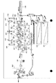
[プリンタ部209の構成(カラーMFP104の場合)]
図9に、カラープリンタ部の概観図を示す。913は、ポリゴンミラーであり、4つの半導体レーザ805より発光された4本のレーザ光を受ける。その内の1本はミラー914、915、916をへて感光ドラム917を走査し、次の1本はミラー918、919、920をへて感光ドラム921を走査し、次の1本はミラー922、923、924をへて感光ドラム925を走査し、次の1本はミラー926、927、928をへて感光ドラム929を走査する。
【0038】
一方、930はイエロー(Y)のトナーを供給する現像器であり、レーザ光に従い、感光ドラム917上にイエローのトナー像を形成し、931はマゼンタ(M)のトナーを供給する現像器であり、レーザ光に従い、感光ドラム921上にマゼンタのトナー像を形成し、932はシアン(C)のトナーを供給する現像器であり、レーザ光に従い、感光ドラム925上にシアンのトナー像を形成し、933はブラック(K)のトナーを供給する現像器であり、レーザ光に従い、感光ドラム929上にマゼンタのトナー像を形成する。以上4色(Y,M,C,K)のトナー像がシートに転写され、フルカラーの出力画像を得ることができる。
【0039】
シートカセット934、935および、手差しトレイ936のいずれかより給紙されたシートは、レジストローラ937を経て、転写ベルト938上に吸着され、搬送される。給紙のタイミングと同期がとられて、予め感光ドラム917、921、925、929には各色のトナーが現像されており、シートの搬送とともに、トナーがシートに転写される。各色のトナーが転写されたシートは、分離され、搬送ベルト939により搬送され、定着器940によって、トナーがシートに定着される。定着器940を抜けたシートはフラッパ950により一旦下方向へ導かれてシートの後端がフラッパ950を抜けた後、スイッチバックさせて排出する。これによりフェイスダウン状態で排出され、先頭頁から順にプリントしたときに正しいページ順となる。
【0040】
なお、4つの感光ドラム917、921、925、929は、距離dをおいて、等間隔に配置されており、搬送ベルト939により、シートは一定速度vで搬送されており、このタイミング同期がなされて、4つの半導体レーザ805は駆動される。
【0041】
[プリンタ部209の構成(モノクロMFP105の場合)]
図10に、モノクロプリンタ部の概観図を示す。1013は、ポリゴンミラーであり、4つの半導体レーザ805より発光されたレーザ光を受ける。レーザ光はミラー1014、1015、1016をへて感光ドラム1017を走査する。一方、1030は黒色のトナーを供給する現像器であり、レーザ光に従い、感光ドラム1017上にトナー像を形成し、トナー像がシートに転写され、出力画像を得ることができる。
【0042】
シートカセット1034、1035および、手差しトレイ1036のいずれかより給紙されたシートは、レジストローラ1037を経て、転写ベルト1038上に吸着され、搬送される。給紙のタイミングと同期がとられて、予め感光ドラム1017にはトナーが現像されており、シートの搬送とともに、トナーがシートに転写される。トナーが転写されたシートは、分離され、定着器1040によって、トナーがシートに定着される。定着器1040を抜けたシートはフラッパ1050により一旦下方向へ導かれてシートの後端がフラッパ1050を抜けた後、スイッチバックさせて排出する。これによりフェイスダウン状態で排出され、先頭頁から順にプリントしたときに正しいページ順となる。
【0043】
[フィニッシャ部209の構成]
図11に、フィニッシャ部の概観図を示す。プリンタ部209の定着部940(または、1040)を出たシートは、フィニッシャ部209に入る。フィニッシャ部209には、サンプルトレイ1101及びスタックトレイ1102があり、ジョブの種類や排出されるシートの枚数に応じて切り替えて排出される。
【0044】
ソート方式には2通りあり、複数のビンを有して各ビンに振り分けるビンソート方式と、後述の電子ソート機能とビン(または、トレイ)を奥手前方向にシフトしてジョブ毎に出力シートを振り分けるシフトソート方式によりソーティングを行うことができる。電子ソート機能は、コレートと呼ばれ、前述のコア部で説明した大容量メモリを持っていれば、このバッファメモリを利用して、バッファリングしたページ順と排出順を変更する、いわゆるコレート機能を用いることで電子ソーティングの機能もサポートできる。次にグループ機能は、ソーティングがジョブ毎に振り分けるのに対し、ページ毎に仕分けする機能である。
【0045】
更に、スタックトレイ1102に排出する場合には、シートが排出される前のシートをジョブ毎に蓄えておき、排出する直前にステープラ1105にてバインドすることも可能である。
【0046】
そのほか、上記2つのトレイに至るまでに、紙をZ字状に折るためのZ折り機1104、ファイル用の2つ(または3つ)の穴開けを行うパンチャ1106があり、ジョブの種類に応じてそれぞれの処理を行う。
【0047】
更に、サドルステッチャ1107は、シートの中央部分を2ヶ所バインドした後に、シートの中央部分をローラに噛ませることによりシートを半折りし、週刊誌やパンフレットのようなブックレットを作成する処理を行う。サドルステッチャ1107で製本されたシートは、ブックレットトレイ1108に排出される。
【0048】
そのほか、図には記載されていないが、製本のためのグルー(糊付け)によるバインドや、あるいはバインド後にバインド側と反対側の端面を揃えるためのトリム(裁断)などを加えることも可能である。
【0049】
また、インサータ1103はトレイ1110にセットされたシートをプリンタへ通さずにトレイ1101、1102、1108のいずれかに送るためのものである。これによってフィニッシャ209に送り込まれるシートとシートの間にインサータ1103にセットされたシートをインサート(中差し)することができる。インサータ1103のトレイ1110にはユーザによりフェイスアップの状態でセットされるものとし、ピックアップローラ1111により最上部のシートから順に給送する。従って、インサータ1103からのシートはそのままトレイ1101、1102へ搬送することによりフェイスダウン状態で排出される。サドルステッチャ1107へ送るときには、一度パンチャ1106側へ送り込んだ後スイッチバックさせて送り込むことによりフェースの向きを合わせる。
【0050】
[ドキュメントサーバ102の構成]
図12を用いてドキュメントサーバ102を説明する。
【0051】
NIC111から入力されたジョブは、入力デバイス制御部1201よりサーバ内に入り、サーバに様々なクライアントアプリケーションと連結することにおいてその役割を果たす。入力としてはPDLデータとJCL(Job Control Language)データを受け付ける。それはプリンタとサーバに関する状態情報で様々なクライアントに対応し、このモジュールの出力は、適切なPDLとJCLの構成要素すべてを結合する役割を持つ。
【0052】
入力ジョブ制御部1202はジョブの要求されたリストを管理し、サーバに提出される個々のジョブにアクセスするために、ジョブリストを作成する。更に、このモジュールには、ジョブのルートを決めるジョブルーティングと、ジョブの順序を決めるジョブスケジューリングの機能がある。
【0053】
ラスタライズ処理(RIP)部1203はPDLをRIP処理して、適切なサイズと解像度のビットマップを作成する。RIP処理部1203は、PostScript(Adobe社の商標登録)をはじめ、PCL、TIFF、JPEG、PDFなど様々なフォーマットのラスタライズ処理が可能である。
【0054】
データ変換部1204は、RIPによって作り出されるビットマップイメージの圧縮およびフォーマット変換を行う。そして、各プリンタにマッチした最適な画像イメージタイプを選び出す。例えば、ジョブをページ単位で扱いたい場合には、TIFFやJPEGなどをRIP部でラスタライズした後のビットマップデータにPDFヘッダを付けて、PDFデータとして編集するなどの処理を行う。
【0055】
出力ジョブ制御部1205は、コマンド設定に基づき、ジョブのページイメージの扱い方を管理する。ページイメージの扱い方としては、例えば、プリンタによる印刷したり、ハードディスクドライブ(HDD)1207にセーブしたりする方法がある。さらに、印刷後のジョブを、ハードディスクドライブ1207にセーブするか否かを選択することも可能であり、セーブされた場合には再呼び出しすることも可能である。さらに、出力ジョブ制御部1205は、ハードディスクドライブ(HDD)1207とRAM1208との相互作用を管理する。
【0056】
出力デバイス制御部1206は、どのデバイスに出力するか、またどのデバイスをクラスタリング(複数台接続して一斉にプリントすること)するかという制御を行う。さらに、出力デバイス制御部1206はデバイス104や105の状態監視と装置状況をドキュメントサーバ102に伝えることも行う。
【0057】
[ページ記述言語とRIP部1203の構成]
一般に、ADOBE社のPostScript(登録商標)に代表されるPDL(Page Description Language:ページ記述言語)で記述されたデータを印刷や表示が可能なビットマップデータに展開することをRIP(Raster Image Processor)と呼ぶ。ハードウェアとソフトウェアでこれを実現するものがあり、それぞれハードウェアRIP、ソフトウェアRIPという。
【0058】
図13にRIP部1203の構成を示す。RIP部1203は、PDLデータを印刷や表示に応じた解像度でビットマップデータに変換するラスタライズ部1301と、カラーマネージメントを司るCMS(Color Management System)部1302及び、CMYK各色のリニアリティを保つためのガンマ補正を行うTRC(Tone Reproduction Curve)部1303から構成される。
【0059】
[ラスタライズ部1301]
一般にPDLデータは以下の3要素に分類されており、原稿画像はこれらの要素の組み合わせで構成される。
(a)文字コードによる画像記述
(b)図形コードによる画像記述
(c)ラスタ画像データによる画像記述
図14−1にPDLデータの記述例を示し、図14−2に図14−1のPDLデータを展開した結果を示す。
【0060】
文字情報の記述例を、文字情報R1401を記述した例を用いて説明する。L1411は、文字の色を指定する記述であり、カッコの中は順にC、M、Y、Bの濃度を表わしている。色指定コマンドの最小値は0.0であり、最大値は1.0である。L1411は文字を黒にすることを指定している。L1412は変数String1に文字列“IC”を代入している。L1413における第1、第2パラメータは文字列をレイアウトする用紙上の開始位置座標のx座標とy座標を示し、第3パラメータは文字の大きさを示し、第4パラメータは文字の間隔を示し、第5パラメータはレイアウトすべき文字列を示している。要するにL1413は座標(0.0, 0.0)のところから、大きさ0.3、間隔0.1で文字列“IC”をレイアウトするという指示となる。
【0061】
図形情報の記述例を、図形情報R1402を記述した例を用いて説明する。L1421はL1411と同様、線の色を指定しており、ここでは、シアンが指定されている。L1422は、線を引くことを指定するためのものであり、第1、2パラメータが線の始端座標、第3、4パラメータが終端座標のそれぞれx座標、y座標である。第5パラメータは線の太さを示す。
【0062】
ラスタ画像情報の記述例を、ラスタ画像情報R1403を記述した例を用いて説明する。L1431は、ラスタ画像を変数image1に代入している。ここで、第1パラメータはラスタ画像の画像タイプ、及び色成分数を表わし、第2パラメータは1色成分あたりのビット数を表わし、第3、第4パラメータは、ラスタ画像のx方向、y方向の画像サイズを表わす。第5パラメータ以降が、ラスタ画像データである。ラスタ画像データの個数は、1画素を構成する色成分数、及び、x方向、y方向の画像サイズの積となる。L1431では、CMYK画像は4つの色成分(Cyan、Magenta、Yellow、Black)から構成されるため、ラスタ画像データの個数は(4x5x5=)100個となる。L1432は、座標(0.0, 0.5)のところから、0.5x0.5の大きさにimage1をレイアウトすることを示している。
【0063】
図14−2は、1ページの中で上記3つの画像記述を解釈して、ラスタ画像データに展開した様子を示したものである。R1401,R1402,R1403はそれぞれのPDLデータを展開したものである。これらのラスタ画像データは、実際にはCMYK色成分毎にRAM1208(あるいは、ImageDisk1207)に展開されており、例えばR1401の部分は、各CMYKのRAM1208に、C=0、M=0、Y=0、K=255が書かれており、R1402の部分は、それぞれ、C=255,M=0,Y=0,K=0が書き込まれる。
【0064】
ドキュメントサーバ102内では、クライアント103(あるいは、ドキュメントサーバ自身)から送られてきたPDLデータは、PDLデータのままか、上記のようにラスタ画像に展開された形で、RAM1208(あるいは、ImageDisk1207)に書き込まれ、必要に応じて保存される。
[CMS(Color Management System)部1302]
図13に示されるCMS部1302は、いわゆるICC(International Color Consortium)Profileと呼ばれる変換テーブルSource Profile(ソースプロファイル)1304やPrinter Profile(プリンタプロファイル)1305を自由に選択することにより、カラーマッチングを行う。つまり、ソースプロファイルに記載されている入力画像データが依存する特性に応じた補正条件と、プリンタプロファイルに記載されているプリンタの特性に応じた補正条件とを用いて、入力画像データを処理する。
【0065】
PDLデータにはRGB系とCMYK系の2種類のデータがあり、後者はAdobe社のPhotoshop(商標登録)やIllustrator(商標登録)などをはじめとするCMYKでデータを扱うことのできる一部のアプリケーションから作成されたPDL(主にPostScript)データであり、それ以外のアプリケーションから作成されたPDL(主にPostScript)データや、TIFF,JPEGと言ったフォーマットのデータにおいてはRGB系として扱われる。
【0066】
一般的にICCプロファイルには、数式列や多次元ルックアップテーブルなどが格納されている。本実施形態では説明を容易にするために、数列式を用いて演算でそれぞれ変換するような方法で説明する。なお、3次元ルックアップテーブルなどの他の形式でも同様に処理することができる。
【0067】
RGB系のPDLデータが入力された場合には、ソースプロファイルに格納されている図15のE1501式を用いて一度RGBデータを規格化されたL*a*b*空間に変換する。このソースプロファイル1304には、S−RGBに代表される各種ディスプレイのプロファイルや、デジタルカメラ、スキャナなどの入力装置のプロファイルなどがあり、デバイスの種類に応じた数列式{a00・・・a22}が格納されている。
【0068】
同様に、CMYK系のデータが入力された場合には、プリンタプロファイルに格納されたE1502式を用いてL*a*b*空間に変換される。SWOP,Euroscale,JapanColorなどのインクの色再現をシミュレーションする場合は、プリンタの種類だけでなくシミュレートする対象に対応させて数列式{b00・・・b23}をソースプロファイルに格納することが必要である。
【0069】
次に、L*a*b*空間からプリンタにあったCMYKデータに変換する。本実施形態ではMFP104aで印刷するので、E1503式を用いて変換を行う。
【0070】
この場合の数列式{c00・・・c32}は各種プリンタの機種毎に用意されている。たとえば、MFP104aとMFP104bが別のタイプの機種であった場合、E1503はMFP104a用のプロファイルであり、E1504はMFP104b用プロファイルと言った具合である。ターゲット機種が変われば、別のプロファイルを選択することになる。
【0071】
また、プリンタプロファイルでは、Perceptual(色相保存)、Colormetric(色差最小)、Saturation(彩度優先)といったRendering Intentと呼ばれるディスプレイや入力装置と出力デバイスとの再現範囲の違いを調整する方法に応じて数列式を複数個用意しておいて選択することもできる。
【0072】
規格化された色空間に一度変換する理由は、スキャナ、ディスプレイなどの様々な入力環境の色を、種々のプリンタという出力環境の異なるものに出力する場合に常に同等の色味を保証するためである。
[TRC(Tone Reproduction Curve)部1303]
TRC部1303は、CMYK各色8ビット(0〜255)で入力される値に対してそれぞれのプリンタの階調特性に応じたガンマ変換を行う。一般に、入力された信号に対して図16−1のようなリニアなテーブルG0によって変換し出力した結果は、リニアな階調特性を有さない。たとえば、図18のようなチャートを出力し、濃度計でその出力濃度を測定すると、図16−2のような出力結果Giとなる。そこで、予めGi(図16−2)の逆関数であるGa(図16−3)のようなガンマテーブルを用いてTRC部で変換することにより、図16−1のようなリニアなプリント出力を得ることができる。
【0073】
GiとGaは互いに逆関数のガンマテーブルであり、Ga*Gi=G0であるため、結果としてリニアな出力結果G0を導き出すこととなる。
【0074】
Giに示されるプリンタの階調特性は、温度、湿度などの環境変動や、プリンタ電源立ち上げやプリント開始からの時経変化、トータルプリント枚数、消耗品の摩耗度合いなどの耐久変化などに応じて刻々変化していくため、定期的にこのガンマテーブルを取り替えなければ常にリニアな画像を得ることができない。
【0075】
そのため、キャリブレーション(リニアライゼーション)のためのツールが必要になる。キャリブレーションツールは、まず、プリンタから図18のようなチャートをプリントする行程と、プリントアウトされたチャートサンプルのそれぞれのパッチ濃度を読みとる行程、そして、読み込まれたパッチ濃度の値に応じてTRC部のガンマテーブルを補正するという3つ行程から成り立っている。ここで、パッチ濃度を読みとるためには、前述のスキャナ部201を利用してもいいし、濃度計を用いても構わない。
【0076】
以上説明した、システムの概要および各機器の各ユニットの説明は、本願各実施形態に共通して用いられる。そして、実施形態2以降では、同一の構成については同一符号を用い、説明を割愛する。
[同種のカラーMFP104の2台接続(高画質処理時)]
TRC部のガンマテーブルはデバイス毎に固有のテーブルであるため、もし同時に2台のカラーMFPに同じPDLデータを一斉に出力しようとしても、それぞれのカラーMFPのリニアリティを保証することができない。
【0077】
そこで、図19のように2回RIP処理を行うことが考えられる。すなわち、入力されたPDLデータを一度ハードディスクドライブ(HDD)1207に格納し、それを2回RIP処理する。その際に、1回目のRIPではMFP104a用のガンマテーブル1701を用いて補正することにより、MFP104a固有のCMYKデータを作り、MFP104aに出力する。そして、2回目のRIPではMFP104b用のガンマテーブル1702を用いて補正することにより、MFP104b固有のCMYKデータを作り、MFP104bに出力する。このように、RIP処理部1203が1つしかなければ、RIP処理は逐次2回行われる。
【0078】
なお、2つのRIP処理部1203aと1203bを備えているのであれば、2つのRIP処理部を用いて並列処理することにより高速に処理することができる。但し、それぞれのRIPモジュール(1203aと1203b)では、それぞれのガンマテーブル(1701と1702)が使用される。
[同種のカラーMFP104の2台接続(高速処理時)]
しかしながら、前述の2回RIP処理を行う方法では、確かに高画質でそれぞれのデバイスに合った色味でプリントアウトされるが、2回RIPを行うが故にRIP時間は2倍となり、プリントパフォーマンスを犠牲にするという欠点がある。
【0079】
そこで、1回のRIP処理でプリントする方法について考える。1回でRIPするには、1つのガンマテーブルを用いることになる。このとき、たとえば、図20のように2つのガンマテーブルGa(1701)とGb(1702)を平均化した新たなガンマテーブルGc(1801)を用いて、MFP104a用RIP処理とMFP104b用のRIP処理を同時に行うことになる。
【0080】
ガンマテーブルGcは、必ずしも平均値を用いなくとも、どちらか一方のガンマテーブルGaまたは、Gbのいずれかを代表して用いてもよい。また、平均値化されたガンマテーブルを作成するには、CMYK各色のガンマテーブルに対して、各色別々に平均値化されたガンマテーブルを作成する必要がある。
【0081】
そして、MFP104aとMFP104bが独立に動かせるように、バッファメモリ1802を用意して、サーバコンピュータ102とそれぞれのMFP間でタイミングをとれるようにしておく。また、MFP104のいずれかがジャムやエラーで止まっている場合を想定して、このバッファメモリに入るCMYKそれぞれのラスタデータをハードディスクドライブ(HDD)1207に格納するようにしてもよい。
【0082】
[高画質モードと高速モードの切り替え]
更に、高画質モードと高速モードを用意して、ユーザに選択させるようにして、高画質モードが選択された場合には、2回RIP処理を行い、それぞれMFP104a用、MFP104b用のガンマテーブルを順次利用し、高速モードが選択された場合には、平均化されたテーブルまたは、MFP104a用かMFP104b用のいずれかのテーブルのうち予め指定されたテーブル1つを選んで1回だけRIP処理し、MFP104aとMFP104bの双方に同時に配信するようにする。
【0083】
高画質モードまたは高速モードの選択する情報はジョブのヘッダ情報に付加され、ジョブ処理時に該情報に基づき自動的に選択されるようにすればよい。
【0084】
(実施形態1の変形例)
上記実施形態1では、高画質処理時において、各カラーMFPに対応したガンマテーブルを用いて複数回のRIPを行っている。これに対して、本変形例では、この各カラーMFPに対応したガンマテーブルを用いた処理を、各MFP装置内のガンマ変換部502(図6)を用いて行う。
【0085】
したがって、本変形例では、RIP部1203において、ラスタライズ部1401を用いたラスタライズ処理およびCMS部1402を用いたカラーマッチング処理を行い、TRC1403を用いたガンマ変換処理は行わない。
【0086】
各カラーMFPのガンマ変換部502を外部(例えばドキュメントサーバー)から制御できる場合は、各カラーMFPのガンマ変換部502をTRC部1403として用いることにより、同種の複数のカラーMFPを用いたクラスタプリントを1回のRIP処理で高画質で実現することができる。
【0087】
なお、キャリブレーションツールを用いてガンマテーブルをキャリブレートした場合は、ガンマ変換部502にキャリブレートしたガンマテーブルをダウンロードする。
【0088】
(実施形態2)
実施形態1では同一機種のカラーMFPを接続する場合を説明した。本実施形態では、実施形態1の変形例として、異機種間のカラーMFPを2台接続した場合を説明する。
【0089】
プリンタプロファイル1405は機種によって異なるため、異機種同士ではTRC部1403のガンマテーブルを変更するだけでは当然色味を合わせることができない。
【0090】
そこで、図21のように、プリンタプロファイル1405を1回目と2回目で変更して、2回RIP処理を行う高画質モードを考える。ここで用いられるプロファイルPa(1901)は、MFP104a用のプロファイルであり、図15のE1503で用いられた数列式である。それに対して、MFP104bの機種が別であれば、機種固有のこの値も別物になり、プロファイルPb(1902)となる。また、当然1回目のRIPと2回目のRIPでガンマテーブルGaとGbも異なるようになり、それぞれのRIP後のデータは、デバイスMFP104aとMFP104bに送られることになる。
【0091】
これに対して、高速モードでは、このプリンタプロファイル1405も1つでなければ高速処理できないため、図22のように数列式E1503で使われるMFP104a用のプロファイルPaと、数列式E2001で使われるMFP104b用のプロファイルPbとを平均値化した数列式E2002を考える。すなわち、Pc=(Pa+Pb)/2というようなプロファイルPcを用いて1回でRIPしてしまうのである。この際には、前述の平均値化されたガンマテーブルGcも用いて一回のRIPで処理される。このとき、色味は多少ずれるが、それぞれのプリンタMFP104aとMFP104bに対して比較的中和された色味でそれぞれ再現されることになる。
【0092】
あるいは、図23のようにラスタライズ部1401を出た後に一度ハードディスクドライブHDD(1207)で一旦保存し、それぞれのプリンタプロファイル1901と1902及び、それぞれのガンマテーブル1701と1702を使ってそれぞれMFP104aとMFP104bに出力することもできる。
【0093】
(実施形態3)
本実施形態では、実施形態1の変形例として、カラーMFP104が3台以上接続された場合について説明する。3台以上接続された場合でも、プリンタプロファイルやガンマテーブルをそれぞれ1回目、2回目、3回目・・・と言った具合に切り替えて扱う高画質モード。プリンタプロファイルやガンマテーブルの平均値を求めて扱う高速モードとして同様に考えることができる。
【0094】
また、3台以上のクラスタリングの場合ならば、必ずしも平均値を用いなくても、モード(代表値)やメジアン(中央値)を用いても構わない。
【0095】
[プロファイル、ガンマテーブルの重み付け係数]
更に、プリンタ自身のプリントスピードに応じてクラスタリングの分配数に重み付けをつけることを考える。いま、図24のようにMFP104aが30ppm、MFP104bが20ppmのとき、2台でクラスタを組んで、プリント終了時間が同じになるように、それぞれ30部と20部に重み付けをしてプリントする場合、MFP104aは全体の3/5の部数がプリントされるので重み付け係数も3/5として、逆にMFP104bは全体の2/5の部数がプリントされるので重み付け係数も2/5として計算するのが、E2201式に表される重み付けプロファイルである。
【0096】
同様にして、ガンマテーブルの方も同機種間で重み付けしてプリントする場合には、それぞれのガンマテーブルに重み付け係数を掛けて計算して、たとえば、Gc=3/5*Ga+2/5*Gbのように新たなガンマテーブルを作成することも可能である。
【0097】
(実施形態4)
上述した実施形態1〜3のいずれを用いるかを、クラスタ処理するプリンタの種類に応じて選択するようにしてもよい。
【0098】
本願実施形態によれば、1つのサーバ102から少なくとも2台のカラーMFP104にクラスタプリントを行う際に、高画質モードと高速モードを用意し、ユーザの設定に基づいて、高画質モードの時には、それぞれのカラーMFPの特性に合わせたプロファイルとガンマテーブルを切り替えて2回のRIP処理を行い、それぞれのカラーMFPにマッチした色味でクラスタプリントを行い、高速モードの際にはそれぞれのカラーMFPの特性の差を最小限に抑えるような色味で1回のRIP処理にて複数台のMFPに同時にクラスタプリントすることにより、高画質と高速の両方のニーズに応えるカラークラスタリングシステムを提供することができる。
【0099】
(実施形態5)
複数台の同種のカラーMFP104を接続して、1回のRIP処理で各デバイス用のデータを作成する方法を提供する。図20に示すように、一方(たとえば、MFP104a)については通常にプリントし、他方(MFP104b)についてはRIP処理の結果に対して補正を行い出力する。即ち、前者(MFP104a)がマスタとなり、後者(MFP104b)がスレブとなる。
【0100】
スレブ側用のデータは、マスタ(MFP104a)用のガンマテーブルを用いて処理されたMFP104a用CMYKデータを、MFP104b用に補正するための補正ガンマテーブル部1801で補正することにより得られる。
【0101】
MFP104a用のCMYKデータに対して、MFP104a用のガンマテーブルGa(図16−3)の逆関数テーブルGi(図16−2)を掛けることにより、TRC部1403前のCMYKデータを得、そして、MFP104b用のガンマテーブルGb(図17)を掛けることによりMFP104bにマッチしたCMYKデータを得る。
【0102】
つまり、補正テーブル部1801に、Gs=Gi*Gbを計算したガンマテーブルGsを設定すればよい。
【0103】
[カラーMFP104が3台以上接続された場合]
3台以上接続された場合には、クラスタプリントする組み合わせは広がる。たとえば、図21のように104a,104b,104cという3台のカラーMFPが接続されていた場合、必ずしも実施形態1のようなマスタ、スレブの関係が作れるわけではない。即ち、クラスタの組み合わせは、(104aと104b)、(104bと104c)、(104cと104a)及び、(104aと104bと104c)となり、104aをマスタにしても、マスタが入らない組み合わせができてしまうためである。従って、104a,104b,104c全てのデバイス用に補正テーブル部を用意しなければならない。
【0104】
MFP104aが実施形態1でいうマスタに相当する場合には、TRC部1403にはMFP104a用のガンマテーブルGaが入り、MFP104a用のテーブル補正部1901にはリニアなガンマテーブルG0、MFP104b用のテーブル補正部1902にはガンマテーブル(Gi*Gb)、そして、MFP104c用のテーブル補正部1903にはガンマテーブル(Gi*Gc但しGcはMFP104c用ガンマテーブル)を設定する。
【0105】
このようにすることで、どの組み合わせでも常に補正されたCMYKデータが1回のRIP処理でそれぞれのカラーMFPに出力することができる。
【0106】
また、改めてキャリブレーションを行うと、TRC部1403のガンマテーブルGaが更新されるため、再度Giも求めなおして、それぞれのテーブル補正部には新たなテーブルが用意されることになる。
【0107】
本実施形態によれば、RIP処理部の数より多い数のプリンタを用いたクラスタ処理を、出力画像の品質を低下させずに高速に行うことができる。
【0108】
実施形態1の変形例と同様に、MFPカラープリンタのガンマ変換部502(図6)を用いても構わない。つまり、補正テーブル部として、スレブのカラーMFPのガンマ変換部502を用いるようにしても構わない。この場合は、スレブのカラーMFPに対して、ガンマテーブルをダウンロードすることになる。
【0109】
[異機種間のクラスタプリント]
次に、クラスタの組み合わせのカラーMFP104が異なる種類の機種であった場合について説明する。プリンタプロファイル1405は機種によって異なるため、異機種同士ではTRC部1403のガンマテーブルを変更するだけでは当然色味を合わせることができない。
【0110】
そこで、ガンマテーブル同様に、プリンタプロファイル1405を補正するプロファイル補正部2001と2002を図22のように追加し、デバイス間の色の差異を補正する。
【0111】
補正に際しては、第1に、CMYKそれぞれの色にルックアップテーブル(ガンマテーブル)で近似した値を算出する方法がある。これは、テーブル補正部と同じ方式であるが、この場合には、テーブル補正部のガンマテーブルと掛け合わせて合成されたルックアップテーブルとして1つにまとめることも可能である。
【0112】
第2に、CMYKデータに数列式を掛けて近似的にデバイスに依存したCMYKを算出する関数演算の方法で求めることもできる。たとえば、図23のE2003ような行列演算で新たなCMYKデータを作ることも可能であるし、ルックアップテーブルと行列演算式の双方でも可能である。
【0113】
また、RIP部1203から出力されるCMYKの画像データを一度ハードディスクドライブHDD(1207)で一旦保存し、それぞれの補正テーブルを通して、それぞれMFP104aとMFP104bあるいは、それ以上のデバイスに出力することもできる。
【0114】
同機種を複数台用いた時のクラスタプリントと異機種を複数台用いた時のクラスタプリントを説明したが、どちらの方法を用いるかは、ドキュメントサーバ102が出力するプリンタの種類を識別し、自動的に選択すればよい。なお、マスタのプリンタについては、予め設定されている優先順位またはジョブ指示にユーザによって指示された情報に基づき設定される。
【0115】
本実施形態によれば、1つのサーバ102から少なくとも2台以上のカラーMFP104にクラスタプリントを行う際に、マスタとなるカラーMFPの特性に合わせた色補正を行いマスタ用の出力データを作成し、そしてスレブとなるカラーMFPの出力のためにマスタ用出力データをスレブ用出力データに補正する補正テーブルを用意し、1回のRIP処理にて、色味の合ったそれぞれの画像データを複数台のカラーMFPに同時にクラスタプリントすることができるカラークラスタリングシステムを提供することができる。
【0116】
(他の実施形態)
また前述した実施形態の機能を実現する様に各種のデバイスを動作させる様に該各種デバイスと接続された装置あるいはシステム内のコンピュータに、前記実施形態機能(例えば、図20〜図22で実現される機能)を実現するためのソフトウエアのプログラムコードを供給し、そのシステムあるいは装置のコンピュータ(CPUあるいはMPU)を格納されたプログラムに従って前記各種デバイスを動作させることによって実施したものも本発明の範疇に含まれる。
【0117】
またこの場合、前記ソフトウエアのプログラムコード自体が前述した実施形態の機能を実現することになり、そのプログラムコード自体、及びそのプログラムコードをコンピュータに供給するための手段、例えばかかるプログラムコードを格納した記憶媒体は本発明を構成する。
【0118】
かかるプログラムコードを格納する記憶媒体としては例えばフロッピーディスク、ハードディスク、光ディスク、光磁気ディスク、CD−ROM、磁気テープ、不揮発性のメモリカード、ROM等を用いることが出来る。
【0119】
またコンピュータが供給されたプログラムコードを実行することにより、前述の実施形態の機能が実現されるだけではなく、そのプログラムコードがコンピュータにおいて稼働しているOS(オペレーティングシステム)、あるいは他のアプリケーションソフト等と共同して前述の実施形態の機能が実現される場合にもかかるプログラムコードは本発明の実施形態に含まれることは言うまでもない。
【0120】
更に供給されたプログラムコードが、コンピュータの機能拡張ボードやコンピュータに接続された機能拡張ユニットに備わるメモリに格納された後そのプログラムコードの指示に基づいてその機能拡張ボードや機能格納ユニットに備わるCPU等が実際の処理の一部または全部を行い、その処理によって前述した実施形態の機能が実現される場合も本発明に含まれることは言うまでもない。
【0121】
【発明の効果】
本発明は入力画像情報をビットマップ画像データに展開する処理(RIP処理)の回数を抑制し、高速に複数のカラー画像出力装置で並列処理することができる。
【0122】
また、ユーザの用途に応じて、高速な処理および高精度な処理を選択することができる。
【図面の簡単な説明】
【図1】本発明の実施形態のシステム全体を示す図(1)。
【図2】本発明の実施形態のシステム全体を示す図(2)。
【図3】画像形成装置全体のブロック図。
【図4】画像形成装置のスキャナ部を示す図。
【図5】画像形成装置のスキャナIP部を示す図。
【図6】画像形成装置のプリンタIP部を示す図。
【図7】画像形成装置のPWM部のブロック図。
【図8】画像形成装置のPWM部のタイミング図。
【図9】カラー画像形成装置のプリンタ部を示す図。
【図10】白黒画像形成装置のプリンタ部を示す図。
【図11】画像形成装置のフィニッシャ部を示す図。
【図12】本発明のドキュメントサーバ内部のジョブフロー。
【図13】RIP部の構成を示す図(1)。
【図14】PDLデータの記述例とそのラスタ展開後を示す図。
【図15】ソースプロファイルとプリンタプロファイルの数列式(1)。
【図16】ガンマカーブを示す図。
【図17】ガンマカーブを示す図。
【図18】キャリブレーションのテストチャート。
【図19】RIP部の構成を示す図(2)。
【図20】RIP部の構成を示す図(3)。
【図21】RIP部の構成を示す図(4)。
【図22】プリンタプロファイルの数列式(2)。
【図23】RIP部の構成を示す図(5)。
【図24】プリンタプロファイルの数列式(3)。
【図25】RIP部の構成を示す図。
【図26】RIP部の構成を示す図。
【図27】RIP部の構成を示す図。
【図28】プロファイル補正部の数列式。[0001]
BACKGROUND OF THE INVENTION
The present invention relates to an image processing method, apparatus, and recording medium for performing image processing for processing input jobs in parallel by a plurality of color image output apparatuses.
[0002]
[Prior art]
A user selects a desired printer using a driver from a desired application on each computer, and instructs printing via a public line such as a LAN or a dedicated interface. Also known as a server / client method, a method in which a client user's job is sent to a printer via a document server is also widely known.
[0003]
In recent years, in the market called print-on-demand, there are increasing cases of printing large numbers of documents such as manuals and instruction manuals, and large numbers of copies as in the light printing industry. A cluster printing concept in which one document in a server or client is simultaneously printed to a plurality of printers has been developed. Further, since the colorization of the document has progressed, a request for outputting a color document using cluster printing has begun.
[0004]
[Problems to be solved by the invention]
In color document cluster printing, the difference in color of output samples in each printer, which was not a problem in black and white document cluster printing, has become a problem. In other words, environmental fluctuations and temporal changes of each printer itself are alleviated to some extent by calibration in each printer, but there are not a few unique characteristics among multiple printers. Subtle differences appear in the output samples. For users, it is sometimes an important problem that the colors of the output samples that have been created at the same time differ from each other even though they are made from the same document. I am worried about the difference in color between printers of the same model, but I am more worried about the difference in color between printers of different models.
[0005]
Color adjustment according to the printer is generally incorporated into a series of operations called a RIP process for converting PDL data into bitmap data. For this reason, only the color matching cannot be removed. For this reason, in order to output to a plurality of color MFPs, a plurality of RIP processes must be performed, which requires a double RIP time.
[0006]
The present invention has been made in view of the above-described drawbacks, and can suppress the number of times of processing (RIP processing) for developing input image information into bitmap image data, and can perform parallel processing at a high speed with a plurality of color image output devices. The purpose is to.
[0007]
It is another object of the present invention to select high-speed processing and high-precision processing according to the user's application.
[0008]
[Means for Solving the Problems]
A first invention of the present application is an image processing method for processing an input job in parallel by a plurality of color image output devices,
A development step of developing input image information into bitmap image data;
The unfolding step has a first mode and a second mode,
In the first mode, the input image information is developed a plurality of times using color processing conditions corresponding to each of the plurality of color image output devices,
In the second mode, the development is performed once using a color processing condition that is an average value, a representative value, or an intermediate value of color processing conditions corresponding to the plurality of color image output apparatuses, and the result of the development is Data is output to the plurality of color image output devices.
[0009]
A second invention of the present application is an image processing method for processing input jobs in parallel by a plurality of color image output devices,
A development step of developing input image information into bitmap image data;
The unfolding step has a first mode and a second mode,
In the first mode, the input image information is developed a plurality of times using color processing conditions corresponding to each of the plurality of color image output devices,
In the second mode, the development is performed once using a color processing condition obtained by multiplying a color processing condition corresponding to the plurality of color image output apparatuses by a weighting factor, and data of the result of the development is obtained. Output to the plurality of color image output devices.
[0010]
DETAILED DESCRIPTION OF THE INVENTION
(Embodiment 1)
[System overview]
1 and 2 are schematic views showing an example of the configuration of a system according to the present embodiment.
[0011]
In FIG. 1, the
[0012]
The
[0013]
[0014]
Further, an MFP (Multi Function Peripheral) 105 is connected to the
[0015]
The MFP 104 is a full color MFP capable of scanning or printing with high resolution and high gradation full color. The MFP 104 may be connected to the
[0016]
In this embodiment, it is considered that at least two full-
[0017]
The hardware configuration of the
[0018]
On the client computer 103, various documents / graphics are created / edited by application software that executes DTP (Desk Top Publishing). The created document / graphic data is converted into a page description language on the client computer 103, transferred to the
[0019]
Each of the
[0020]
[Configuration of
The configuration of the
[0021]
The
[0022]
Next, the image data output from the core unit 206 is sent to the
[0023]
[Configuration of Scanner Unit 201]
The configuration of the
[0024]
[Configuration of Scanner IP Unit 202]
The
[0025]
Next, the
[0026]
Further, the luminance / density conversion unit (LOG conversion unit) 405 is configured by a look-up table (LUT) RAM, and converts RGB luminance signals into density signals of C1 (cyan), M1 (magenta), and Y1 (yellow). .
[0027]
[Configuration of
The
[0028]
The dedicated I /
[0029]
[Configuration of Core Unit 206]
The
[0030]
The path switching pattern for executing each function is shown below.
Copy function:
Network scan:
Network print:
The image data output from the bus selector unit 611 is sent to the
[0031]
Furthermore, if a job number and password are provided and stored together, the personal box function can be supported. This is a function for temporarily storing data and allowing only a specific person to print out (read from the HDD). When an instruction to print out a stored job is issued, authentication is performed using a password, and then a call is made from the
[0032]
[Configuration of Printer IP Unit 207]
The printer IP unit will be described with reference to FIG.
[0033]
[0034]
The
[0035]
[Configuration of PWM unit 208]
The
[0036]
The
[0037]
[Configuration of Printer 209 (for Color MFP 104)]
FIG. 9 shows an overview of the color printer unit. A
[0038]
On the other hand, 930 is a developing device that supplies yellow (Y) toner, forms a yellow toner image on the
[0039]
A sheet fed from any one of the
[0040]
The four
[0041]
[Configuration of Printer Unit 209 (for Monochrome MFP 105)]
FIG. 10 shows an overview of the monochrome printer unit. A
[0042]
A sheet fed from one of the
[0043]
[Configuration of Finisher 209]
FIG. 11 shows an overview of the finisher section. The sheet exiting the fixing unit 940 (or 1040) of the
[0044]
There are two sort methods: a bin sort method that has a plurality of bins and distributes the bins, and an electronic sort function and a bin (or tray), which will be described later, are shifted in the front direction to distribute output sheets for each job. Sorting can be performed by the shift sort method. The electronic sort function is called collate. If you have the large-capacity memory described in the core section above, the so-called collate function is used to change the buffered page order and discharge order using this buffer memory. It can also support electronic sorting functions. Next, the group function is a function for sorting by page, while sorting is sorted by job.
[0045]
Further, when the sheets are discharged to the
[0046]
In addition to the above two trays, there are a Z-
[0047]
Further, the
[0048]
In addition, although not shown in the drawing, it is also possible to add binding by glue (glue) for bookbinding or trim (cutting) for aligning the end surface opposite to the binding side after binding.
[0049]
An
[0050]
[Configuration of Document Server 102]
The
[0051]
A job input from the
[0052]
The input
[0053]
A rasterization processing (RIP)
[0054]
The
[0055]
The output
[0056]
The output
[0057]
[Configuration of Page Description Language and RIP Unit 1203]
In general, RIP (Raster Image Processor) is to develop data described in PDL (Page Description Language) represented by PostScript (registered trademark) of ADOBE into bitmap data that can be printed and displayed. Call it. There are hardware and software that realize this, and they are called hardware RIP and software RIP, respectively.
[0058]
FIG. 13 shows the configuration of the
[0059]
[Rasterize unit 1301]
In general, PDL data is classified into the following three elements, and a document image is composed of a combination of these elements.
(A) Image description by character code
(B) Image description by graphic code
(C) Image description using raster image data
FIG. 14-1 shows a description example of PDL data, and FIG. 14-2 shows a result of developing the PDL data of FIG. 14-1.
[0060]
A description example of character information will be described using an example in which character information R1401 is described. L1411 is a description for designating the color of the character, and the C, M, Y, and B densities are shown in parentheses in order. The minimum value of the color designation command is 0.0, and the maximum value is 1.0. L1411 specifies that the character is black. L1412 assigns the character string “IC” to the variable String1. The first and second parameters in L1413 indicate the x and y coordinates of the start position coordinates on the paper on which the character string is laid out, the third parameter indicates the character size, the fourth parameter indicates the character spacing, The fifth parameter indicates a character string to be laid out. In short, L1413 is an instruction to lay out the character string “IC” with a size of 0.3 and an interval of 0.1 from the coordinates (0.0, 0.0).
[0061]
A description example of graphic information will be described using an example in which graphic information R1402 is described. Similarly to L1411, L1421 designates a line color, and cyan is designated here. L1422 is used to specify that a line is to be drawn. The first and second parameters are the start coordinate of the line, and the third and fourth parameters are the x coordinate and the y coordinate of the end coordinate, respectively. The fifth parameter indicates the thickness of the line.
[0062]
A description example of raster image information will be described using an example in which raster image information R1403 is described. L1431 substitutes the raster image for the variable image1. Here, the first parameter represents the image type and the number of color components of the raster image, the second parameter represents the number of bits per color component, and the third and fourth parameters are the x direction and y direction of the raster image. Represents the image size. The fifth and subsequent parameters are raster image data. The number of raster image data is the product of the number of color components constituting one pixel and the image size in the x and y directions. In L1431, since the CMYK image is composed of four color components (Cyan, Magenta, Yellow, Black), the number of raster image data is (4 × 5 × 5 =) 100. L1432 indicates that image1 is laid out in the size of 0.5 × 0.5 from the coordinates (0.0, 0.5).
[0063]
FIG. 14-2 shows a state in which the above three image descriptions are interpreted in one page and developed into raster image data. R1401, R1402, and R1403 are developed from the respective PDL data. These raster image data are actually expanded in the RAM 1208 (or ImageDisk 1207) for each CMYK color component. For example, the R1401 portion is stored in each
[0064]
In the
[CMS (Color Management System) 1302]
A
[0065]
There are two types of PDL data, RGB and CMYK. The latter includes some applications that can handle data in CMYK, such as Adobe Photoshop (registered trademark) and Illustrator (registered trademark). PDL (mainly PostScript) data created from the above, and PDL (mainly PostScript) data created from other applications and data in formats such as TIFF and JPEG are handled as RGB.
[0066]
In general, an ICC profile stores a formula string, a multidimensional lookup table, and the like. In the present embodiment, in order to facilitate the description, a description will be given of a method in which each is converted by calculation using a sequence expression. The same processing can be performed in other formats such as a three-dimensional lookup table.
[0067]
When RGB PDL data is input, the RGB data is once converted into a standardized L * a * b * space using the E1501 equation of FIG. 15 stored in the source profile. The
[0068]
Similarly, when CMYK data is input, it is converted into the L * a * b * space using the E1502 equation stored in the printer profile. When simulating the color reproduction of ink such as SWOP, Euroscale, and JapanColor, it is necessary to store the sequence {b00... B23} in the source profile corresponding to the simulation target as well as the type of printer. is there.
[0069]
Next, the L * a * b * space is converted into CMYK data suitable for the printer. In this embodiment, since printing is performed by the
[0070]
The sequence {c00... C32} in this case is prepared for each type of printer. For example, when the
[0071]
Also, in the printer profile, a sequence according to a method of adjusting the reproduction range difference between a display or an input device and an output device called Rendering Intent such as Perceptual (hue storage), Colormetric (minimum color difference), and Saturation (saturation priority) A plurality of expressions can be prepared and selected.
[0072]
The reason for converting to the standardized color space once is to guarantee the same color when always outputting colors of various input environments such as scanners and displays to different output environments of various printers. is there.
[TRC (Tone Reproduction Curve) unit 1303]
The TRC unit 1303 performs gamma conversion corresponding to the gradation characteristics of each printer on the value input with 8 bits (0 to 255) of each color of CMYK. In general, a result obtained by converting and outputting an input signal using a linear table G0 as shown in FIG. 16A does not have linear gradation characteristics. For example, when a chart as shown in FIG. 18 is output and the output density is measured with a densitometer, an output result Gi as shown in FIG. 16-2 is obtained. Therefore, a linear print output as shown in FIG. 16-1 is obtained by converting the TRC unit in advance using a gamma table such as Ga (FIG. 16-3) which is an inverse function of Gi (FIG. 16-2). Obtainable.
[0073]
Since Gi and Ga are gamma tables having inverse functions, and Ga * Gi = G0, a linear output result G0 is derived as a result.
[0074]
The gradation characteristics of the printer shown in Gi depend on environmental fluctuations such as temperature and humidity, changes with time since the printer power was turned on and printing started, changes in durability such as the total number of prints and the degree of wear of consumables, etc. Since it changes every moment, a linear image cannot always be obtained unless this gamma table is periodically replaced.
[0075]
Therefore, a tool for calibration (linearization) is required. First, the calibration tool performs the process of printing the chart as shown in FIG. 18 from the printer, the process of reading each patch density of the printed chart sample, and the TRC unit according to the read patch density value. It consists of three steps of correcting the gamma table. Here, in order to read the patch density, the
[0076]
The outline of the system and the description of each unit of each device described above are commonly used in the embodiments of the present application. In the second and subsequent embodiments, the same reference numerals are used for the same components, and descriptions thereof are omitted.
[Connect two
Since the gamma table of the TRC unit is a table unique to each device, even if the same PDL data is simultaneously output to two color MFPs, the linearity of each color MFP cannot be guaranteed.
[0077]
Therefore, it is conceivable to perform RIP processing twice as shown in FIG. That is, the input PDL data is once stored in the hard disk drive (HDD) 1207, and is subjected to RIP processing twice. At this time, in the first RIP, correction is performed using the gamma table 1701 for the
[0078]
If two RIP processing units 1203a and 1203b are provided, high-speed processing can be performed by performing parallel processing using the two RIP processing units. However, the respective RIP modules (1203a and 1203b) use the respective gamma tables (1701 and 1702).
[Connect two
However, in the method of performing the RIP processing twice described above, the printout is surely performed with high image quality and a color suitable for each device. However, since the RIP is performed twice, the RIP time is doubled and the print performance is improved. There is a disadvantage of sacrificing.
[0079]
Therefore, consider a method of printing in one RIP process. One gamma table is used for RIP at a time. At this time, for example, using the new gamma table Gc (1801) obtained by averaging two gamma tables Ga (1701) and Gb (1702) as shown in FIG. 20, the RIP processing for the
[0080]
The gamma table Gc does not necessarily use an average value, but may represent either one of the gamma tables Ga or Gb. In addition, in order to create an averaged gamma table, it is necessary to create an averaged gamma table for each color for each of the CMYK color gamma tables.
[0081]
Then, a
[0082]
[Switching between high-quality mode and high-speed mode]
Further, a high-quality mode and a high-speed mode are prepared and the user selects them. When the high-quality mode is selected, the RIP process is performed twice, and the gamma tables for the
[0083]
Information to be selected for the high-quality mode or the high-speed mode may be added to the job header information and automatically selected based on the information at the time of job processing.
[0084]
(Modification of Embodiment 1)
In the first embodiment, the RIP is performed a plurality of times using the gamma table corresponding to each color MFP during the high image quality processing. On the other hand, in this modification, processing using the gamma table corresponding to each color MFP is performed using the gamma conversion unit 502 (FIG. 6) in each MFP apparatus.
[0085]
Therefore, in the present modification, the
[0086]
When the
[0087]
When the gamma table is calibrated using the calibration tool, the calibrated gamma table is downloaded to the
[0088]
(Embodiment 2)
In the first embodiment, the case where color MFPs of the same model are connected has been described. In this embodiment, as a modification of the first embodiment, a case where two color MFPs of different types are connected will be described.
[0089]
Since the
[0090]
Therefore, as shown in FIG. 21, a high image quality mode in which the
[0091]
On the other hand, in the high-speed mode, only one
[0092]
Alternatively, as shown in FIG. 23, after exiting the
[0093]
(Embodiment 3)
In this embodiment, a case where three or
[0094]
Further, in the case of clustering of three or more units, the mode (representative value) or the median (median value) may be used without necessarily using the average value.
[0095]
[Weighting coefficient of profile and gamma table]
Further, consider weighting the number of clustering distributions according to the printing speed of the printer itself. Now, as shown in FIG. 24, when the
[0096]
Similarly, when the gamma table is printed with weighting between the same models, the respective gamma tables are calculated by multiplying each gamma table by a weighting coefficient, for example, Gc = 3/5 * Ga + 2/5 * Gb It is also possible to create a new gamma table.
[0097]
(Embodiment 4)
Which of the above-described first to third embodiments is used may be selected according to the type of printer to be clustered.
[0098]
According to the present embodiment, when performing cluster printing from one
[0099]
(Embodiment 5)
A method is provided in which a plurality of
[0100]
The data for the slave side is obtained by correcting the CMYK data for
[0101]
The CMYK data for the
[0102]
That is, the gamma table Gs obtained by calculating Gs = Gi * Gb may be set in the
[0103]
[When three or
When three or more units are connected, combinations for cluster printing are expanded. For example, when three
[0104]
When the
[0105]
By doing so, CMYK data always corrected in any combination can be output to each color MFP in one RIP process.
[0106]
When calibration is performed again, the gamma table Ga of the
[0107]
According to the present embodiment, cluster processing using a larger number of printers than the number of RIP processing units can be performed at high speed without reducing the quality of the output image.
[0108]
Similar to the modification of the first embodiment, the gamma conversion unit 502 (FIG. 6) of the MFP color printer may be used. That is, the
[0109]
[Cluster print between different models]
Next, a case where the
[0110]
Therefore, like the gamma table,
[0111]
In the correction, first, there is a method of calculating a value approximated by a lookup table (gamma table) for each color of CMYK. This is the same method as the table correction unit, but in this case, it is also possible to combine them into one lookup table synthesized by multiplying with the gamma table of the table correction unit.
[0112]
Secondly, it can be obtained by a function calculation method of multiplying CMYK data by a numerical formula and calculating CMYK approximately depending on the device. For example, new CMYK data can be created by a matrix operation such as E2003 in FIG. 23, and both a lookup table and a matrix operation expression are possible.
[0113]
Also, the CMYK image data output from the
[0114]
The cluster print when using a plurality of the same model and the cluster print when using a plurality of different models have been described. Which method is used depends on the type of printer output by the
[0115]
According to the present embodiment, when performing cluster printing from one
[0116]
(Other embodiments)
Further, the functions of the above-described embodiment (for example, implemented in FIGS. 20 to 22) are performed on an apparatus or a computer in the system connected to the various devices so as to operate the various devices so as to realize the functions of the above-described embodiments. The program implemented by operating the various devices according to a program stored in the computer (CPU or MPU) of the system or apparatus is provided. include.
[0117]
In this case, the software program code itself realizes the functions of the above-described embodiments, and the program code itself and means for supplying the program code to the computer, for example, the program code are stored. The storage medium constitutes the present invention.
[0118]
As a storage medium for storing the program code, for example, a floppy disk, a hard disk, an optical disk, a magneto-optical disk, a CD-ROM, a magnetic tape, a nonvolatile memory card, a ROM, or the like can be used.
[0119]
Further, by executing the program code supplied by the computer, not only the functions of the above-described embodiments are realized, but also the OS (operating system) in which the program code is running on the computer, or other application software, etc. It goes without saying that the program code is also included in the embodiment of the present invention even when the functions of the above-described embodiment are realized in cooperation with the embodiment.
[0120]
Further, the supplied program code is stored in the memory provided in the function expansion board of the computer or the function expansion unit connected to the computer, and then the CPU provided in the function expansion board or function storage unit based on the instruction of the program code However, it is needless to say that the present invention also includes a case where the function of the above-described embodiment is realized by performing part or all of the actual processing.
[0121]
【The invention's effect】
The present invention suppresses the number of times of processing (RIP processing) for developing input image information into bitmap image data, and enables parallel processing at a high speed by a plurality of color image output devices.
[0122]
Further, high-speed processing and high-precision processing can be selected according to the user's application.
[Brief description of the drawings]
FIG. 1 is a diagram (1) showing an entire system according to an embodiment of the present invention;
FIG. 2 is a diagram (2) showing the entire system of the embodiment of the present invention.
FIG. 3 is a block diagram of the entire image forming apparatus.
FIG. 4 is a diagram illustrating a scanner unit of the image forming apparatus.
FIG. 5 is a diagram illustrating a scanner IP unit of the image forming apparatus.
FIG. 6 is a diagram illustrating a printer IP unit of the image forming apparatus.
FIG. 7 is a block diagram of a PWM unit of the image forming apparatus.
FIG. 8 is a timing chart of a PWM unit of the image forming apparatus.
FIG. 9 is a diagram illustrating a printer unit of a color image forming apparatus.
FIG. 10 is a diagram illustrating a printer unit of a monochrome image forming apparatus.
FIG. 11 is a diagram illustrating a finisher unit of the image forming apparatus.
FIG. 12 is a job flow inside the document server of the present invention.
FIG. 13 is a diagram (1) showing a configuration of a RIP unit.
FIG. 14 is a diagram showing a description example of PDL data and its raster development.
FIG. 15 is a numerical expression (1) of a source profile and a printer profile.
FIG. 16 is a diagram showing a gamma curve.
FIG. 17 is a diagram showing a gamma curve.
FIG. 18 is a calibration test chart.
FIG. 19 is a diagram (2) showing a configuration of a RIP unit;
FIG. 20 is a diagram (3) showing the configuration of the RIP unit;
FIG. 21 is a diagram (4) showing a configuration of a RIP unit;
FIG. 22 is a numerical sequence (2) of printer profiles.
FIG. 23 is a diagram (5) illustrating a configuration of a RIP unit;
FIG. 24 is a numerical sequence (3) of printer profiles.
FIG. 25 is a diagram showing a configuration of a RIP unit.
FIG. 26 is a diagram showing a configuration of a RIP unit.
FIG. 27 is a diagram showing a configuration of a RIP unit.
FIG. 28 is a sequence expression of the profile correction unit.
Claims (4)
入力画像情報をビットマップ画像データに展開する展開工程を有し、
前記展開工程は第一のモードと第二のモードを有し、
前記第一のモードは、前記入力画像情報を前記複数台のカラー画像出力装置の夫々に対応した色処理条件を用いて、複数回前記展開を行い、
前記第二のモードは、前記複数台のカラー画像出力装置に対応した色処理条件の平均値もしくは代表値もしくは中間値である色処理条件を用いて前記展開を1回行い、前記展開の結果のデータを前記複数台のカラー画像出力装置に出力することを特徴とする画像処理方法。An image processing method for processing input jobs in parallel on a plurality of color image output devices,
A development step of developing input image information into bitmap image data;
The unfolding step has a first mode and a second mode,
In the first mode, the input image information is developed a plurality of times using color processing conditions corresponding to each of the plurality of color image output devices,
In the second mode, the development is performed once using a color processing condition that is an average value, a representative value, or an intermediate value of color processing conditions corresponding to the plurality of color image output devices, and the result of the development is An image processing method comprising: outputting data to the plurality of color image output devices.
入力画像情報をビットマップ画像データに展開する展開工程を有し、
前記展開工程は第一のモードと第二のモードを有し、
前記第一のモードは、前記入力画像情報を前記複数台のカラー画像出力装置の夫々に対応した色処理条件を用いて、複数回前記展開を行い、
前記第二のモードは、前記複数台のカラー画像出力装置に対応した色処理条件に重み係数を掛けて求められた色処理条件を用いて前記展開を1回行い、前記展開の結果のデータを前記複数台のカラー画像出力装置に出力することを特徴とする画像処理方法。An image processing method for processing input jobs in parallel on a plurality of color image output devices,
A development step of developing input image information into bitmap image data;
The unfolding step has a first mode and a second mode,
In the first mode, the input image information is developed a plurality of times using color processing conditions corresponding to each of the plurality of color image output devices,
In the second mode, the development is performed once using a color processing condition obtained by multiplying a color processing condition corresponding to the plurality of color image output devices by a weighting factor, and data of the result of the development is obtained. An image processing method for outputting to the plurality of color image output devices.
入力画像情報をビットマップ画像データに展開する展開手段と、
前記展開工程は第一のモードと第二のモードを選択する選択手段とを有し、
前記第一のモードは、前記入力画像情報を前記複数台のカラー画像出力装置の夫々に対応した色処理条件を用いて、複数回前記展開を行い、
前記第二のモードは、前記複数台のカラー画像出力装置に対応した色処理条件に重み係数を掛けて求められた色処理条件を用いて前記展開を1回行い、前記展開の結果のデータを前記複数台のカラー画像出力装置に出力することを特徴とする画像処理装置。An image processing device for processing input jobs in parallel with a plurality of color image output devices,
Development means for developing input image information into bitmap image data;
The expanding step has a selection means for selecting the first mode and the second mode,
In the first mode, the input image information is developed a plurality of times using color processing conditions corresponding to each of the plurality of color image output devices,
In the second mode, the development is performed once using a color processing condition obtained by multiplying a color processing condition corresponding to the plurality of color image output devices by a weighting factor, and data of the result of the development is obtained. An image processing apparatus that outputs to the plurality of color image output apparatuses.
Priority Applications (3)
| Application Number | Priority Date | Filing Date | Title |
|---|---|---|---|
| JP2001226078A JP4532790B2 (en) | 2000-08-08 | 2001-07-26 | Color image processing method, apparatus and program |
| US09/922,647 US7433062B2 (en) | 2000-08-08 | 2001-08-07 | Color image processing method and apparatus, and storage medium |
| EP01306737A EP1185080B1 (en) | 2000-08-08 | 2001-08-07 | Color image processing method and apparatus, and storage medium |
Applications Claiming Priority (5)
| Application Number | Priority Date | Filing Date | Title |
|---|---|---|---|
| JP2000239752 | 2000-08-08 | ||
| JP2000-239752 | 2000-08-08 | ||
| JP2000-239753 | 2000-08-08 | ||
| JP2000239753 | 2000-08-08 | ||
| JP2001226078A JP4532790B2 (en) | 2000-08-08 | 2001-07-26 | Color image processing method, apparatus and program |
Related Child Applications (1)
| Application Number | Title | Priority Date | Filing Date |
|---|---|---|---|
| JP2008193169A Division JP4546561B2 (en) | 2000-08-08 | 2008-07-28 | Image processing apparatus and image processing method |
Publications (3)
| Publication Number | Publication Date |
|---|---|
| JP2002152545A JP2002152545A (en) | 2002-05-24 |
| JP2002152545A5 JP2002152545A5 (en) | 2008-09-11 |
| JP4532790B2 true JP4532790B2 (en) | 2010-08-25 |
Family
ID=27344288
Family Applications (1)
| Application Number | Title | Priority Date | Filing Date |
|---|---|---|---|
| JP2001226078A Expired - Fee Related JP4532790B2 (en) | 2000-08-08 | 2001-07-26 | Color image processing method, apparatus and program |
Country Status (3)
| Country | Link |
|---|---|
| US (1) | US7433062B2 (en) |
| EP (1) | EP1185080B1 (en) |
| JP (1) | JP4532790B2 (en) |
Families Citing this family (29)
| Publication number | Priority date | Publication date | Assignee | Title |
|---|---|---|---|---|
| US20030007177A1 (en) * | 2001-01-11 | 2003-01-09 | Ferlitsch Andrew R. | Scan-to-cluster printing |
| JP2003036159A (en) * | 2001-05-15 | 2003-02-07 | Fuji Xerox Co Ltd | Print processing method and apparatus, print instruction method and apparatus, print control method and apparatus |
| EP1351487A3 (en) * | 2002-04-04 | 2007-01-24 | Fuji Photo Film Co. Ltd. | Method, apparatus and program storage medium for color conversion |
| JP2004046339A (en) | 2002-07-09 | 2004-02-12 | Seiko Epson Corp | Control of a plurality of printers |
| JP4254285B2 (en) * | 2003-03-20 | 2009-04-15 | 富士ゼロックス株式会社 | Data processing system and method |
| JP2004291278A (en) * | 2003-03-25 | 2004-10-21 | Dainippon Screen Mfg Co Ltd | Color management method and system in plate-making printing system |
| CN100382073C (en) * | 2003-03-27 | 2008-04-16 | 佳能株式会社 | Image forming system, control method of the image forming system, program and storage medium |
| US20040239965A1 (en) * | 2003-05-30 | 2004-12-02 | Xerox Corporation | Systems and methods for generating source color space interpretations |
| JP2005271371A (en) * | 2004-03-24 | 2005-10-06 | Fuji Xerox Co Ltd | Printing managing device, printing managing method, printing managing program and printing system |
| US20050248584A1 (en) * | 2004-05-10 | 2005-11-10 | Koji Takeo | Imaging system and image processing apparatus |
| JP4095581B2 (en) * | 2004-06-09 | 2008-06-04 | キヤノン株式会社 | Information processing apparatus and control method thereof |
| JP4073905B2 (en) * | 2004-10-25 | 2008-04-09 | シャープ株式会社 | Image processing apparatus, image forming apparatus, image forming system, image forming program, image processing program, and computer-readable recording medium |
| US7791751B2 (en) * | 2004-11-30 | 2010-09-07 | Palo Alto Research Corporation | Printing systems |
| JP4360335B2 (en) * | 2005-03-15 | 2009-11-11 | セイコーエプソン株式会社 | Color image forming apparatus, color image forming system, color image processing method and program |
| US7697151B2 (en) * | 2005-03-25 | 2010-04-13 | Xerox Corporation | Image quality control method and apparatus for multiple marking engine systems |
| JP4599220B2 (en) * | 2005-05-12 | 2010-12-15 | キヤノン株式会社 | Image processing system and method |
| US8149438B2 (en) * | 2006-02-28 | 2012-04-03 | Xerox Corporation | Distributed printing system with improved load balancing |
| JP2007257372A (en) | 2006-03-23 | 2007-10-04 | Fujitsu Ltd | Image processor |
| JP2007266740A (en) * | 2006-03-27 | 2007-10-11 | Noritsu Koki Co Ltd | Print processing system |
| JP4878250B2 (en) * | 2006-09-15 | 2012-02-15 | 株式会社リコー | Image processing apparatus, image processing method, and image processing program |
| GB0618412D0 (en) * | 2006-09-19 | 2006-11-01 | Punch Graphix Int Nv | Near press 4-color N-color conversion method and system for late binding of press details in a RIP-less color conversion or documented CMYK workflow |
| JP2008078800A (en) * | 2006-09-19 | 2008-04-03 | Ricoh Co Ltd | Image forming apparatus |
| US20090059321A1 (en) * | 2007-08-31 | 2009-03-05 | Xerox Corporation | System and Method for Generating Color-Correct Scanned Image Files in a Network Environment |
| JPWO2010082321A1 (en) * | 2009-01-14 | 2012-06-28 | 株式会社ミマキエンジニアリング | Program, image forming method, and printing system |
| JP5731847B2 (en) * | 2011-02-16 | 2015-06-10 | キヤノン株式会社 | Image processing apparatus and image processing method |
| US9639193B2 (en) | 2013-04-25 | 2017-05-02 | Beijing Boe Optoelectronics Technology Co., Ltd. | Touch-control pixel driving circuit, touch-control pixel driving method, array substrate and liquid crystal display (LCD) device |
| JP5835286B2 (en) * | 2013-08-14 | 2015-12-24 | コニカミノルタ株式会社 | Image forming method, program for image forming system, recording medium recording program for image forming system, and image forming system |
| JP6797805B2 (en) * | 2015-02-19 | 2020-12-09 | キャノン プロダクション プリンティング ネザーランド ビーブイ | Color matching printer |
| JP2023085703A (en) * | 2021-12-09 | 2023-06-21 | 株式会社リコー | Image processing apparatus, image forming system, image processing method, and program |
Citations (4)
| Publication number | Priority date | Publication date | Assignee | Title |
|---|---|---|---|---|
| JPH08207363A (en) * | 1994-08-31 | 1996-08-13 | Canon Inc | Picture image processing device and method |
| JPH11177825A (en) * | 1997-12-11 | 1999-07-02 | Fuji Xerox Co Ltd | Image processor |
| JPH11179978A (en) * | 1997-12-19 | 1999-07-06 | Dainippon Screen Mfg Co Ltd | Image processing device, image processing method, and storage medium |
| JPH11282446A (en) * | 1998-03-30 | 1999-10-15 | Canon Inc | Image processing method and recording medium |
Family Cites Families (9)
| Publication number | Priority date | Publication date | Assignee | Title |
|---|---|---|---|---|
| US5271096A (en) | 1990-07-12 | 1993-12-14 | Light Source Computer Images, Inc. | Method and structure for calibrating a computer generated image |
| US5852674A (en) | 1991-04-08 | 1998-12-22 | Canon Kabushiki Kaisha | Apparatus and method for processing images using position-dependent weighing factor |
| US5608549A (en) | 1991-06-11 | 1997-03-04 | Canon Kabushiki Kaisha | Apparatus and method for processing a color image |
| US5467434A (en) * | 1992-08-28 | 1995-11-14 | Xerox Corporation | Apparatus and method for determining printer option availability and representing conflict resolution in a combination of print job selections |
| JPH07147639A (en) * | 1993-11-22 | 1995-06-06 | Canon Inc | Device and system for forming image |
| US6035103A (en) * | 1995-08-07 | 2000-03-07 | T/R Systems | Color correction for multiple print engine system with half tone and bi-level printing |
| JP3618912B2 (en) | 1996-07-12 | 2005-02-09 | キヤノン株式会社 | Image forming apparatus |
| JP3852657B2 (en) * | 1999-11-30 | 2006-12-06 | コニカミノルタビジネステクノロジーズ株式会社 | Color management system, color management method, recording medium, and profile creation method |
| US6738151B1 (en) * | 2000-05-26 | 2004-05-18 | Kabushiki Kaisha Toshiba | Distributed processing system for image forming apparatus |
-
2001
- 2001-07-26 JP JP2001226078A patent/JP4532790B2/en not_active Expired - Fee Related
- 2001-08-07 US US09/922,647 patent/US7433062B2/en not_active Expired - Fee Related
- 2001-08-07 EP EP01306737A patent/EP1185080B1/en not_active Expired - Lifetime
Patent Citations (4)
| Publication number | Priority date | Publication date | Assignee | Title |
|---|---|---|---|---|
| JPH08207363A (en) * | 1994-08-31 | 1996-08-13 | Canon Inc | Picture image processing device and method |
| JPH11177825A (en) * | 1997-12-11 | 1999-07-02 | Fuji Xerox Co Ltd | Image processor |
| JPH11179978A (en) * | 1997-12-19 | 1999-07-06 | Dainippon Screen Mfg Co Ltd | Image processing device, image processing method, and storage medium |
| JPH11282446A (en) * | 1998-03-30 | 1999-10-15 | Canon Inc | Image processing method and recording medium |
Also Published As
| Publication number | Publication date |
|---|---|
| JP2002152545A (en) | 2002-05-24 |
| EP1185080A3 (en) | 2005-01-12 |
| EP1185080B1 (en) | 2012-11-28 |
| US7433062B2 (en) | 2008-10-07 |
| US20020054314A1 (en) | 2002-05-09 |
| EP1185080A2 (en) | 2002-03-06 |
Similar Documents
| Publication | Publication Date | Title |
|---|---|---|
| JP4532790B2 (en) | Color image processing method, apparatus and program | |
| US7809807B2 (en) | Image forming system, image forming method, and server | |
| JP4086378B2 (en) | Image forming system | |
| JP2002055798A (en) | Image forming system and jig to be used for the system | |
| JP2007041391A (en) | Image forming apparatus | |
| JP4546561B2 (en) | Image processing apparatus and image processing method | |
| JP4280434B2 (en) | Information processing apparatus, information processing apparatus control method, and program | |
| JP4336438B2 (en) | Printing device | |
| JP2007166305A (en) | Image processing apparatus | |
| JP3919358B2 (en) | Image forming system | |
| JP2003223310A (en) | Image forming method and document server | |
| JP3870011B2 (en) | Image forming system, control method, and storage medium | |
| JP2004306303A (en) | Image formation device | |
| JP2002166602A (en) | Image processor, its controlling method, and image processing system | |
| JP4280433B2 (en) | Information processing apparatus, information processing apparatus control method, image forming system, image forming system control method, and program | |
| JP2006268466A (en) | Image forming apparatus system | |
| JP2003330667A (en) | Network device controller | |
| JP4250505B2 (en) | Information processing apparatus, information processing method and information processing program applied to the apparatus | |
| JP2005104045A (en) | Image forming method and image forming device | |
| JP2006252118A (en) | Image forming apparatus system | |
| JP2003008814A (en) | Information processor, control method for the information processor, program, and storage medium | |
| JP2005135005A (en) | Information processor, image forming system, image forming method and control program | |
| JP2007011820A (en) | Image forming device system | |
| JP2007026175A (en) | Image forming system | |
| JP2005110035A (en) | Method and device for forming image |
Legal Events
| Date | Code | Title | Description |
|---|---|---|---|
| A521 | Request for written amendment filed |
Free format text: JAPANESE INTERMEDIATE CODE: A523 Effective date: 20080728 |
|
| A621 | Written request for application examination |
Free format text: JAPANESE INTERMEDIATE CODE: A621 Effective date: 20080728 |
|
| A977 | Report on retrieval |
Free format text: JAPANESE INTERMEDIATE CODE: A971007 Effective date: 20090814 |
|
| A131 | Notification of reasons for refusal |
Free format text: JAPANESE INTERMEDIATE CODE: A131 Effective date: 20090825 |
|
| A521 | Request for written amendment filed |
Free format text: JAPANESE INTERMEDIATE CODE: A523 Effective date: 20091022 |
|
| A131 | Notification of reasons for refusal |
Free format text: JAPANESE INTERMEDIATE CODE: A131 Effective date: 20091117 |
|
| A521 | Request for written amendment filed |
Free format text: JAPANESE INTERMEDIATE CODE: A523 Effective date: 20100114 |
|
| RD04 | Notification of resignation of power of attorney |
Free format text: JAPANESE INTERMEDIATE CODE: A7424 Effective date: 20100201 |
|
| TRDD | Decision of grant or rejection written | ||
| A01 | Written decision to grant a patent or to grant a registration (utility model) |
Free format text: JAPANESE INTERMEDIATE CODE: A01 Effective date: 20100518 |
|
| A01 | Written decision to grant a patent or to grant a registration (utility model) |
Free format text: JAPANESE INTERMEDIATE CODE: A01 |
|
| A61 | First payment of annual fees (during grant procedure) |
Free format text: JAPANESE INTERMEDIATE CODE: A61 Effective date: 20100611 |
|
| R150 | Certificate of patent or registration of utility model |
Free format text: JAPANESE INTERMEDIATE CODE: R150 |
|
| FPAY | Renewal fee payment (event date is renewal date of database) |
Free format text: PAYMENT UNTIL: 20130618 Year of fee payment: 3 |
|
| LAPS | Cancellation because of no payment of annual fees |