JP4530245B2 - Membrane separator - Google Patents
Membrane separator Download PDFInfo
- Publication number
- JP4530245B2 JP4530245B2 JP2002168097A JP2002168097A JP4530245B2 JP 4530245 B2 JP4530245 B2 JP 4530245B2 JP 2002168097 A JP2002168097 A JP 2002168097A JP 2002168097 A JP2002168097 A JP 2002168097A JP 4530245 B2 JP4530245 B2 JP 4530245B2
- Authority
- JP
- Japan
- Prior art keywords
- hollow fiber
- gas
- membrane
- skirt structure
- membrane separation
- Prior art date
- Legal status (The legal status is an assumption and is not a legal conclusion. Google has not performed a legal analysis and makes no representation as to the accuracy of the status listed.)
- Expired - Lifetime
Links
Images


Landscapes
- Separation Using Semi-Permeable Membranes (AREA)
Description
【0001】
【発明の属する技術分野】
本発明は、水処理に使用する膜分離装置に関する。
【0002】
【従来の技術】
従来、浄水処理、産業排水処理、下水処理などには、凝集沈殿・砂ろ過や沈降分離といった物理的固液分離法が行われてきた。この固液分離を膜分離で高度に処理する事が、処理水質、水質の安全性、管理の容易さなどから、近年注目されている。特に、濁質の高い膜ろ過原水の場合、原水の入った槽、タンク、ピットなどに直接分離膜を浸漬し、吸引もしくは重力ろ過する方法が有望である。このような膜分離装置の特徴は、下部から気体を散気する事によって、膜面の濁質を除去することができる。特開2000−107573号公報には、中空糸を懸垂して支持したタンク型ろ過装置において、中空糸の下部から気体または液体を均一に供給する為の制限オリフィスを設けたタンク型のろ過膜洗浄装置が開示されている。この装置は、タンク式の膜ろ過装置としては極めて有効なものの、気体流量が多い場合、気体流動の圧力損失が大きく、流量によっては、低圧の吐出圧のブロアが使用できないという問題があった。
【0003】
特開平5−277345号公報には、上下方向の筒状のケーシングとろ過膜エレメントからなり、エレメント下部に500mm以上かつ2000mm以下の筒状のケーシングと空気吹き込み口を設けた膜ろ過装置が開示されている。下部のケーシング部分で空気を分散させるゾーンを設けたもので、膜エレメント下部に500mm以上の空間が必要になり、深さ方向が有効に使用できないといった問題があった。
【0004】
【発明が解決しようとする課題】
本発明は、このような膜面洗浄に必要な気体を均一に分散し、中空糸膜カートリッジの中空糸の周辺に汚泥等が蓄積することを防ぎ、長時間安定な膜ろ過性能を示す膜分離装置を提供することを目的とするものである。
【0005】
【課題を解決するための手段】
本発明者らは、鋭意検討の結果、多数本の中空糸膜からなり、両端部が接着固定され、上部に中空糸の開口を有し、下部に気体導入用のスカート構造と該気体を中空糸外表面に導入する気体導入孔を有する垂直方向に設置した中空糸膜カートリッジと、該スカート構造部の下部に気体散気孔を有する膜分離装置において、中空糸膜カートリッジ1個あたり気体散気孔が複数個あることを特徴とする膜分離装置とすることで、長期間安定なろ過性能を示す膜ろ過装置を発明するに至った。
【0006】
すなわち、本発明は下記の通りである。
1.多数本の中空糸膜からなり、両端部が接着固定され、上部に中空糸の開口を有し、下部に気体導入用のスカート構造部と該スカート構造部上面(中空糸下端接合面)に該気体を中空糸外表面に均一に供給するように設けた円相当直径6〜30mmの貫通孔である6個以上の気体導入孔を有し、かつ垂直方向に設置される中空糸膜カートリッジと、円相当直径が6〜30mmの気体散気孔を有し、該スカート構造の下部に設置される散気装置から構成される膜分離装置であって、前記気体散気孔を中空糸膜カートリッジ1個あたり複数個有し、かつ前記スカート構造の上部部分の面積40平方センチメートルあたり気体散気孔を1個以上有することを特徴とする浸漬用膜分離装置。
2.請求項1記載の中空糸膜カートリッジを用い、散気と同時にろ過原水を吸引ろ過する膜分離装置の運転方法。
3.ろ過原水が活性汚泥処理水である請求項2に記載の膜分離装置の運転方法。
【0007】
中空糸膜を用いて濁質等の固形分を含む溶液から固形分を分離し、清澄なろ過液を得るには、ろ過と同時に下部から気体を散気し、気体が上昇する時のスクラビング効果によって、膜の表面の液流れに乱流を与え、濁質などを除去する膜ろ過装置が有効である。この膜ろ過を長期安定に運転するには、中空糸膜に気体を均一に散気することが重要になる。これには、下部にスカート構造部と気体導入孔を持つ構造の中空糸膜カートリッジが、空間の利用率が高く、散気した気体が中空糸膜の表面に効率良くあたり有効である。スカート構造部は、下部より散気した気体を気体導入孔に均一に分配する為のものだが、気体流量が大きくなったり、気体の噴出圧力が高くなると気体導入孔への気体の分散が不充分になる。本発明者らは、スカート構造部下部に簡単な構造の散気構造を持つ膜分離装置が、濁質の高いろ過原水をろ過する場合、きわめて有効でることを見いだした。スカート構造部下部にある気体散気装置の散気孔を複数固設けることで、散気する気体を分散し、上部の複数個の気体導入孔に均一に導入することが、膜ろ過性能を長期に安定に保つのに有効である。
【0008】
【発明の実施の形態】
以下、本発明について、その好ましい実施態様を中心に説明する。
本発明を構成する散気装置の気体散気孔の円相当直径は、濁質の種類と量にもよるが、6mm〜30mmが好ましい。この気体散気孔の円相当直径は、濁質の気体散気孔への詰まり防止、気体散気の圧力損失防止の点で6mm以上、気体散気の圧力変動防止、濁質の気体散気孔流入防止の点で30mm以下が好ましい。
【0009】
さらに、気体散気孔の数は、スカート構造部の水平方向の断面積40平方センチメートルあたり1個以上あることが、散気した気体を上部の気体導入孔に均一に分散するのに好ましい。本願でいう「スカート構造部の上部部分の面積」とは、気体導入孔に最も近いスカート構造部分の、モジュールの断面方向の面積のことである。また、ほぼ同じ円相当直径を有する気体散気孔を複数設けることが構造上好ましい。
【0010】
また、気体散気孔の散気方向は、通常、上方であるが、下方に向けて散気しても構わない。散気方向が下方の方が、気体散気孔が閉塞しにくくなる。
本発明の気体導入孔は、円相当直径が6から30mmの貫通穴であることが好ましい。気体導入孔は散気した気体を中空糸に均一に供給する為のものであるが、気体導入孔の円相当直径は、濁質の詰まりを防止し、長期安定な膜分離性能を維持する点で6mm以上、中空糸に気体を均一に供給し中空糸間に濁質を滞留させない観点から30mm以下が好ましい。
【0011】
また、気体導入孔の形状は、通常円形であるあるが、楕円や三角形、四角形の多角形や星型であっても良い。
ここでいう導入気体は、ろ過原水が活性汚泥である時は、空気や酸素であり、ろ過原水が発酵液である時は窒素ガスや反応ガスとなる。
【0012】
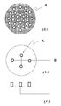
以下、図面により本発明の実施態様を説明する。図1に本発明の膜分離装置を構成する中空糸膜カートリッジと散気装置を示す。1は中空糸膜であり、逆浸透膜、限外濾過膜、精密濾過膜などの通常の濁質除去に用いる膜を使用する。また、中空糸膜1の素材は、特に限定されず、ポリスルホン、ポリエーテルスルホン、ポリアクリロニトリル、ポリイミド、ポリエーテルイミド、 ポリアミド、ポリエーテルケトン、ポリエーテルエーテルケトン、ポリエチレン、ポリプロピレン、ポリー4メ チルペンテン、親水化ポリエチレン、セルロース、酢酸セルロース、ポリビニルアルコール、ポリフッ化ビニリデン、ポリエチレンーテトラフルオロエチレン共重合体、ポリテトラフルオロエチレン等が挙げられる。または、これらの複合素材膜も使用できる。
【0013】
中空糸膜カートリッジは、垂直方向に設置し、上部の集水部2に接続した集水管からろ過水をポンプ吸引、サイフォンもしくはヘッド加圧により得る。
図1に示すような膜分離装置を活性汚泥等の高濁質のろ過原水に浸漬して使用する場合がある。図1に示す6はろ過原水であり、スカート構造部3の下部へ、散気装置7の複数個の気体散気孔5から気体を散気する。散気された気体は、スカート構造部に滞留しながらスカート構造部内に均一に分散され、気体導入孔4を通って、上部の中空糸外表面に散気される。ろ過原水はこの散気された気体のガスリフト効果で、周辺部より中空糸へ供給され、ろ過され、清澄なろ過水が得られる。
【0014】
【実施例】
本発明の実施例を以下に説明する。
【0015】
【実施例1】
図2に示す様な、スカート構造部に10mmの気体導入孔を有する中空糸膜カートリッジと、スカート構造部下部に設置する内径10mmの2個の気体散気孔を有する散気装置から構成される膜分離装置を準備した。中空糸膜の膜面積は7平方メートルで、素材はポリフッ化ビニリデン製の精密ろ過膜を用いた。有効長は1000mmであり、中空糸接着部の樹脂部の直径は90mmであり、スカート構造部の面積は、64平方センチメートルであった。即ち、32平方センチメートルあたりに1個の気体散気孔を持つことになる。この膜分離装置を高濃度の活性汚泥に浸漬し、空気を下部より散気しながらろ過した。散気装置から5Nm3/hrの空気を散気しつつ、吸引ポンプで膜ろ過流束が0.6m3/膜面積m2/日となる様に吸引ろ過した。この時の、膜間差圧は、20kPaで一ヶ月間安定であった。
【0016】
評価期間の活性汚泥槽の濃度MLSSは、平均10,000mg/Lであり、温度は25゜Cであった。
活性汚泥の処理水には、下記の組成の合成下水を用い、BOD−SS負荷が0.03kg/kg/日の負荷を与えた。
合成下水組成(g/L)は、ペプトン0.35、肉エキス0.23、尿素0.059、NaCL0.059、KCL0.015、CaCL2 0.015、MgSO4 0.012、K2HPO4 0.935、KH2PO4 0.117、水道水 1(L)を用いた。
【0017】
【実施例2】
図3に示す様な、スカート構造部に10mmの気体導入孔を有する中空糸膜カートリッジと、スカート下部に設置する内径10mm の4個の気体散気孔を有する散気装置から構成される膜分離装置を準備した。中空糸膜の膜面積は25平方メートルで、素材はポリフッ化ビニリデン製の精密ろ過膜を用いた。有効長は1000mmであり、中空糸接着部の樹脂部の直径は167mmであり、スカート部の面積は、167平方センチメートルであった。42平方センチメートルあたりに1個の気体散気孔を持つことになる。この中空糸膜エレメントを高濃度の活性汚泥に浸漬し、空気を下部より散気しながらろ過した。散気装置から18Nm3/hrの空気を曝気しつつ、吸引ポンプで膜ろ過流束が0.6m3/膜面積m2/日となる様に吸引ろ過した。この時の、膜間差圧は、20kPaで一ヶ月間安定であった。
【0018】
評価期間の活性汚泥槽の濃度MLSSは、平均10,000mg/Lであり、温度は25゜Cであった。
【0019】
【比較例1】
実施例1と全く同じ中空糸膜カートリッジとスカート構造部下部に設置する内径10mm の1個の気体散気孔を有する図4に示すような散気装置から構成される膜分離装置を準備した。スカート構造部部の面積は、64平方センチメートルであった。即ち、64平方センチメートルあたりに1個の気体散気孔を持つことになる。下部の散気管から5Nm3/hrの空気を曝気しつつ、吸引ポンプで膜ろ過流速が0.6m3/膜面積m2/日となる様に吸引ろ過した。膜間差圧は、20kPaから1ヶ月間で徐々に上昇し、50kPaまで達した。中空糸膜カートリッジを観察すると、気体導入孔の一部が閉塞して、中空糸膜の周囲に多量の汚泥が付着していた。
【0020】
活性汚泥槽の濃度MLSSは、10,000mg/Lであり、温度は25゜Cであった。
【0021】
【発明の効果】
多数本の中空糸膜からなり、両端部が接着固定され、上部に中空糸の開口を有し、下部に気体導入用のスカート構造部と該気体を中空糸外表面に導入する気体導入孔を有し、かつ垂直方向に設置される中空糸膜カートリッジと、気体散気孔を有し、該スカート構造部の下部に設置される散気装置から構成される膜分離装置において、中空糸膜カートリッジ1個あたり気体散気孔が複数個あることを特徴とする膜分離装置を使用する事で、膜面洗浄に必要な気体を均一に分散し、中空糸膜カートリッジの中空糸の周辺に汚泥等が蓄積することを防ぎ、長時間安定な膜ろ過性能を実現することが可能になった。
【図面の簡単な説明】
【図1】本発明の実施態様を模式的に説明する概略図であり、(a)はその断面図、(b)はそのスカート構造部の底面図である。
【図2】実施例1に用いた膜分離装置を模式的に説明する概略図であり、(a)はスカート構造部上部の水平断面図、(b)は気体散気孔を示す平面図、(c)はその側面図である。なお、(b)の破線はスカート構造部の外形投影線であり、気体散気孔とスカート構造部の位置関係を示す。
【図3】実施例2に用いた膜分離装置を模式的に説明する概略図であり、(a)はスカート構造部上部の水平断面図、(b)は気体散気孔を示す平面図、(c)はその側面図である。なお、(b)の破線はスカート構造部の外形投影線であり、気体散気孔とスカート構造部の位置関係を示す。
【図4】比較例1に用いた膜分離装置を模式的に説明する概略図であり、(a)はスカート構造部上部の水平断面図、(b)は気体散気孔を示す平面図、(c)はその側面図である。なお、(b)の破線はスカート構造部の外形投影線であり、気体散気孔とスカート構造部の位置関係を示す。
【符号の説明】
1 中空糸
2 ろ過水の集水部
3 スカート構造部
4 気体導入孔
5 気体散気孔
6 ろ過原水
7 散気装置
8 導入気体
9 ろ過原水+導入気体[0001]
BACKGROUND OF THE INVENTION
The present invention relates to a membrane separation apparatus used for water treatment.
[0002]
[Prior art]
Conventionally, physical solid-liquid separation methods such as coagulation sedimentation, sand filtration, and sedimentation separation have been performed for water purification treatment, industrial wastewater treatment, sewage treatment, and the like. In recent years, attention has been paid to the advanced treatment of this solid-liquid separation by membrane separation from the viewpoint of the quality of treated water, the safety of water quality, the ease of management, and the like. In particular, in the case of raw membrane filtration raw water with high turbidity, a method of directly immersing the separation membrane in a tank, tank, pit or the like containing raw water and performing suction or gravity filtration is promising. The feature of such a membrane separator is that the turbidity on the membrane surface can be removed by diffusing gas from below. Japanese Patent Application Laid-Open No. 2000-107573 discloses a tank-type filtration membrane cleaning device provided with a restriction orifice for uniformly supplying a gas or liquid from the lower part of a hollow fiber in a tank-type filtration device in which a hollow fiber is suspended and supported. An apparatus is disclosed. Although this device is extremely effective as a tank-type membrane filtration device, there is a problem that when the gas flow rate is large, the pressure loss of the gas flow is large, and depending on the flow rate, a blower having a low discharge pressure cannot be used.
[0003]
Japanese Patent Application Laid-Open No. 5-277345 discloses a membrane filtration device comprising a cylindrical casing in the vertical direction and a filtration membrane element, and having a cylindrical casing of 500 mm or more and 2000 mm or less and an air blowing port at the lower part of the element. ing. Since the lower casing portion is provided with a zone for dispersing air, a space of 500 mm or more is required below the membrane element, and there is a problem that the depth direction cannot be used effectively.
[0004]
[Problems to be solved by the invention]
The present invention provides a membrane separation that uniformly disperses the gas necessary for such membrane surface cleaning, prevents the accumulation of sludge around the hollow fiber of the hollow fiber membrane cartridge, and exhibits stable membrane filtration performance for a long time. The object is to provide an apparatus.
[0005]
[Means for Solving the Problems]
As a result of intensive studies, the present inventors have made a number of hollow fiber membranes, both ends of which are bonded and fixed, the hollow fiber opening at the upper part, and the gas introduction skirt structure and the gas hollow at the lower part. In a hollow fiber membrane cartridge installed in a vertical direction having a gas introduction hole to be introduced into the outer surface of the yarn, and a membrane separation apparatus having a gas diffusion hole in the lower part of the skirt structure, the gas diffusion hole per hollow fiber membrane cartridge By using a membrane separator characterized by having a plurality of membrane separators, the inventors have invented a membrane filtration device that exhibits stable filtration performance for a long period of time.
[0006]
That is, the present invention is as follows.
1. Consisting of a plurality of hollow fiber membranes, both ends are bonded and fixed, the hollow fiber opening is at the top, the gas introduction skirt structure and the skirt structure top surface (hollow fiber bottom joint surface) A hollow fiber membrane cartridge having six or more gas introduction holes, which are through-holes having a circle-equivalent diameter of 6 to 30 mm , provided so as to uniformly supply gas to the outer surface of the hollow fiber, and installed in the vertical direction; has a gas diffuser pores of a circle
2. A method for operating a membrane separation device using the hollow fiber membrane cartridge according to
3. The method for operating the membrane separation apparatus according to
[0007]
In order to separate solids from a solution containing solids such as turbidity using a hollow fiber membrane and obtain a clear filtrate, gas is diffused from the bottom simultaneously with filtration and the scrubbing effect when the gas rises Therefore, a membrane filtration device that gives turbulent flow to the liquid flow on the surface of the membrane and removes turbidity is effective. In order to operate this membrane filtration stably for a long period of time, it is important to uniformly diffuse gas into the hollow fiber membrane. For this purpose, a hollow fiber membrane cartridge having a structure having a skirt structure and a gas introduction hole in the lower portion has a high space utilization rate, and the diffused gas is efficiently applied to the surface of the hollow fiber membrane. The skirt structure is for evenly distributing the gas diffused from the lower part to the gas introduction holes. However, if the gas flow rate is increased or the gas ejection pressure is increased, the gas is not sufficiently dispersed in the gas introduction holes. become. The inventors of the present invention have found that a membrane separation device having a simple structure of a diffuser structure at the lower part of the skirt structure is extremely effective when filtering raw raw water with high turbidity. By providing a plurality of air diffuser holes in the lower part of the skirt structure, the diffused gas can be dispersed and uniformly introduced into the upper gas inlet holes for long-term membrane filtration performance. It is effective to keep stable.
[0008]
DETAILED DESCRIPTION OF THE INVENTION
Hereinafter, the present invention will be described focusing on preferred embodiments thereof.
The equivalent circle diameter of the gas diffuser of the diffuser constituting the present invention is preferably 6 mm to 30 mm, although it depends on the type and amount of the suspended matter. The equivalent circle diameter of the gas diffuser is 6 mm or more in terms of preventing clogging of the turbid gas diffuser, preventing pressure loss of the gas diffuser, preventing pressure fluctuation of the gas diffuser, and preventing inflow of the turbid gas diffuser. In this respect, 30 mm or less is preferable.
[0009]
Furthermore, the number of gas diffuser holes is preferably at least one per 40 square centimeters in the horizontal cross-sectional area of the skirt structure portion in order to uniformly disperse the diffused gas in the upper gas introduction holes. The “area of the upper portion of the skirt structure portion” referred to in the present application is the area of the skirt structure portion closest to the gas introduction hole in the cross-sectional direction of the module. Further, it is preferable in terms of structure to provide a plurality of gas diffusion holes having substantially the same equivalent circle diameter.
[0010]
Further, the direction of air diffusion of the gas diffusion holes is usually upward, but it may be diffused downward. The gas diffusion holes are less likely to be blocked when the air diffusion direction is lower.
The gas introduction hole of the present invention is preferably a through hole having an equivalent circle diameter of 6 to 30 mm. The gas introduction hole is used to uniformly supply the diffused gas to the hollow fiber, but the circle equivalent diameter of the gas introduction hole prevents clogging of turbidity and maintains stable membrane separation performance for a long period of time. Is preferably 30 mm or less from the viewpoint of uniformly supplying gas to the hollow fibers and preventing turbidity from staying between the hollow fibers.
[0011]
The shape of the gas introduction hole is usually a circle, but may be an ellipse, a triangle, a quadrilateral polygon or a star.
The introduced gas here is air or oxygen when the raw filter water is activated sludge, and nitrogen gas or reactive gas when the raw filter water is a fermentation broth.
[0012]
Hereinafter, embodiments of the present invention will be described with reference to the drawings. FIG. 1 shows a hollow fiber membrane cartridge and a diffuser constituting the membrane separation device of the present invention.
[0013]
The hollow fiber membrane cartridge is installed in the vertical direction, and filtrated water is obtained by pump suction, siphon or head pressurization from a water collecting pipe connected to the upper
A membrane separation apparatus as shown in FIG. 1 may be used by immersing it in a highly turbid filtered raw water such as activated sludge.
[0014]
【Example】
Examples of the present invention will be described below.
[0015]
[Example 1]
A membrane composed of a hollow fiber membrane cartridge having a 10 mm gas introduction hole in the skirt structure as shown in FIG. 2 and an air diffuser having two gas diffusion holes having an inner diameter of 10 mm installed at the lower part of the skirt structure. A separation device was prepared. The membrane area of the hollow fiber membrane was 7 square meters, and the material used was a microfiltration membrane made of polyvinylidene fluoride. The effective length was 1000 mm, the diameter of the resin part of the hollow fiber bonded part was 90 mm, and the area of the skirt structure part was 64 square centimeters. That is, one gas diffusion hole is provided per 32 square centimeters. This membrane separator was immersed in high-concentration activated sludge and filtered while air was diffused from below. While air of 5 Nm 3 / hr was diffused from the air diffuser, suction filtration was performed with a suction pump so that the membrane filtration flux was 0.6 m 3 / membrane area m 2 / day. The transmembrane pressure difference at this time was 20 kPa and was stable for one month.
[0016]
The concentration MLSS of the activated sludge tank during the evaluation period was an average of 10,000 mg / L, and the temperature was 25 ° C.
Synthetic sewage having the following composition was used as the treated water of the activated sludge, and a BOD-SS load was given a load of 0.03 kg / kg / day.
Synthetic wastewater composition (g / L), the peptone 0.35, meat extract 0.23, urea 0.059, NaCL0.059, KCL0.015, CaCL 2 0.015,
[0017]
[Example 2]
As shown in FIG. 3, a membrane separator comprising a hollow fiber membrane cartridge having a 10 mm gas introduction hole in the skirt structure and four gas diffusion holes having an inner diameter of 10 mm installed under the skirt. Prepared. The membrane area of the hollow fiber membrane was 25 square meters, and the material used was a microfiltration membrane made of polyvinylidene fluoride. The effective length was 1000 mm, the diameter of the resin part of the hollow fiber bonding part was 167 mm, and the area of the skirt part was 167 square centimeters. There will be one gas diffuser per 42 square centimeters. This hollow fiber membrane element was immersed in high-concentration activated sludge and filtered while air was diffused from below. While aspirating the air of 18 Nm 3 / hr from the air diffuser, suction filtration was performed with a suction pump so that the membrane filtration flux was 0.6 m 3 / membrane area m 2 / day. The transmembrane pressure difference at this time was 20 kPa and was stable for one month.
[0018]
The concentration MLSS of the activated sludge tank during the evaluation period was an average of 10,000 mg / L, and the temperature was 25 ° C.
[0019]
[Comparative Example 1]
A membrane separation apparatus comprising the same hollow fiber membrane cartridge as in Example 1 and an air diffuser as shown in FIG. 4 having one gas diffuser with an inner diameter of 10 mm installed under the skirt structure was prepared. The area of the skirt structure portion was 64 square centimeters. That is, one gas diffusion hole is provided per 64 square centimeters. While aeration of 5 Nm 3 / hr of air from the lower diffusing tube, suction filtration was performed with a suction pump so that the membrane filtration flow rate was 0.6 m 3 / membrane area m 2 / day. The transmembrane pressure difference gradually increased from 20 kPa over one month and reached 50 kPa. When the hollow fiber membrane cartridge was observed, a part of the gas introduction hole was blocked, and a large amount of sludge was adhered around the hollow fiber membrane.
[0020]
The concentration MLSS of the activated sludge tank was 10,000 mg / L, and the temperature was 25 ° C.
[0021]
【The invention's effect】
It consists of a number of hollow fiber membranes, both ends are bonded and fixed, the hollow fiber opening is at the top, the skirt structure for introducing gas and the gas introduction hole for introducing the gas to the outer surface of the hollow fiber at the bottom A hollow fiber membrane cartridge having a hollow fiber membrane cartridge installed in a vertical direction and a gas diffusion hole, and a gas diffusion device installed at the lower part of the skirt structure portion. By using a membrane separation device characterized by multiple gas diffusion holes per unit, the gas required for membrane surface cleaning is uniformly dispersed, and sludge accumulates around the hollow fiber of the hollow fiber membrane cartridge It has become possible to achieve stable membrane filtration performance for a long time.
[Brief description of the drawings]
FIG. 1 is a schematic view schematically illustrating an embodiment of the present invention, in which (a) is a sectional view thereof and (b) is a bottom view of a skirt structure portion thereof.
2A and 2B are schematic views schematically explaining the membrane separation apparatus used in Example 1, wherein FIG. 2A is a horizontal sectional view of an upper part of a skirt structure, and FIG. 2B is a plan view showing gas diffusion holes; c) is a side view thereof. In addition, the broken line of (b) is an outline projection line of a skirt structure part, and shows the positional relationship of a gas diffusion hole and a skirt structure part.
3A and 3B are schematic views schematically explaining the membrane separation apparatus used in Example 2, wherein FIG. 3A is a horizontal sectional view of the upper part of the skirt structure, and FIG. 3B is a plan view showing gas diffusion holes; c) is a side view thereof. In addition, the broken line of (b) is an outline projection line of a skirt structure part, and shows the positional relationship of a gas diffusion hole and a skirt structure part.
4A and 4B are schematic views schematically explaining the membrane separation apparatus used in Comparative Example 1, wherein FIG. 4A is a horizontal sectional view of the upper part of the skirt structure, and FIG. 4B is a plan view showing gas diffusion holes; c) is a side view thereof. In addition, the broken line of (b) is an outline projection line of a skirt structure part, and shows the positional relationship of a gas diffusion hole and a skirt structure part.
[Explanation of symbols]
DESCRIPTION OF
Claims (3)
Priority Applications (1)
| Application Number | Priority Date | Filing Date | Title |
|---|---|---|---|
| JP2002168097A JP4530245B2 (en) | 2002-06-10 | 2002-06-10 | Membrane separator |
Applications Claiming Priority (1)
| Application Number | Priority Date | Filing Date | Title |
|---|---|---|---|
| JP2002168097A JP4530245B2 (en) | 2002-06-10 | 2002-06-10 | Membrane separator |
Publications (2)
| Publication Number | Publication Date |
|---|---|
| JP2004008981A JP2004008981A (en) | 2004-01-15 |
| JP4530245B2 true JP4530245B2 (en) | 2010-08-25 |
Family
ID=30435095
Family Applications (1)
| Application Number | Title | Priority Date | Filing Date |
|---|---|---|---|
| JP2002168097A Expired - Lifetime JP4530245B2 (en) | 2002-06-10 | 2002-06-10 | Membrane separator |
Country Status (1)
| Country | Link |
|---|---|
| JP (1) | JP4530245B2 (en) |
Families Citing this family (33)
| Publication number | Priority date | Publication date | Assignee | Title |
|---|---|---|---|---|
| AUPR421501A0 (en) | 2001-04-04 | 2001-05-03 | U.S. Filter Wastewater Group, Inc. | Potting method |
| AUPR692401A0 (en) | 2001-08-09 | 2001-08-30 | U.S. Filter Wastewater Group, Inc. | Method of cleaning membrane modules |
| AUPS300602A0 (en) | 2002-06-18 | 2002-07-11 | U.S. Filter Wastewater Group, Inc. | Methods of minimising the effect of integrity loss in hollow fibre membrane modules |
| JP4611982B2 (en) | 2003-08-29 | 2011-01-12 | シーメンス・ウォーター・テクノロジーズ・コーポレーション | Backwash method |
| US8808540B2 (en) | 2003-11-14 | 2014-08-19 | Evoqua Water Technologies Llc | Module cleaning method |
| WO2005092799A1 (en) | 2004-03-26 | 2005-10-06 | U.S. Filter Wastewater Group, Inc. | Process and apparatus for purifying impure water using microfiltration or ultrafiltration in combination with reverse osmosis |
| JP4838248B2 (en) | 2004-09-07 | 2011-12-14 | シーメンス・ウォーター・テクノロジーズ・コーポレーション | Reduction of backwash liquid waste |
| EP1799334B1 (en) | 2004-09-14 | 2013-12-11 | Siemens Water Technologies LLC | Methods and apparatus for removing solids from a membrane module |
| JP2006082001A (en) * | 2004-09-15 | 2006-03-30 | Asahi Kasei Chemicals Corp | Membrane separator |
| WO2006029465A1 (en) | 2004-09-15 | 2006-03-23 | Siemens Water Technologies Corp. | Continuously variable aeration |
| CN100546701C (en) | 2004-12-24 | 2009-10-07 | 西门子水技术公司 | Simple gas scouring method and device |
| CN100548451C (en) | 2004-12-24 | 2009-10-14 | 西门子水技术公司 | Cleaning in the membrane filtration system |
| NZ562786A (en) | 2005-04-29 | 2010-10-29 | Siemens Water Tech Corp | Chemical clean for membrane filter |
| ATE511911T1 (en) | 2005-08-22 | 2011-06-15 | Siemens Industry Inc | WATER FILTRATION ARRANGEMENT TO MINIMIZE BACKWASH VOLUME |
| WO2008051546A2 (en) | 2006-10-24 | 2008-05-02 | Siemens Water Technologies Corp. | Infiltration/inflow control for membrane bioreactor |
| US8318028B2 (en) | 2007-04-02 | 2012-11-27 | Siemens Industry, Inc. | Infiltration/inflow control for membrane bioreactor |
| US9764288B2 (en) | 2007-04-04 | 2017-09-19 | Evoqua Water Technologies Llc | Membrane module protection |
| WO2008153818A1 (en) | 2007-05-29 | 2008-12-18 | Siemens Water Technologies Corp. | Membrane cleaning with pulsed airlift pump |
| JP5030690B2 (en) * | 2007-07-06 | 2012-09-19 | 三菱レイヨン株式会社 | Hollow fiber membrane module |
| JP2013500144A (en) | 2008-07-24 | 2013-01-07 | シーメンス インダストリー インコーポレイテッド | Method and filtration system for providing structural support to a filtration membrane module array in a filtration system |
| JP2010188278A (en) * | 2009-02-18 | 2010-09-02 | Kobelco Eco-Solutions Co Ltd | Gas diffuser, membrane module, membrane separator, gas diffusion method and membrane separation method |
| AU2010257526A1 (en) | 2009-06-11 | 2012-01-12 | Siemens Industry, Inc | Methods for cleaning a porous polymeric membrane and a kit for cleaning a porous polymeric membrane |
| ES2738898T3 (en) | 2010-04-30 | 2020-01-27 | Evoqua Water Tech Llc | Fluid flow distribution device |
| CN103118766B (en) | 2010-09-24 | 2016-04-13 | 伊沃夸水处理技术有限责任公司 | The fluid of membrane filtration system controls manifold |
| CN103958024B (en) | 2011-09-30 | 2016-07-06 | 伊沃夸水处理技术有限责任公司 | The manifold arrangement improved |
| HUE058060T2 (en) | 2011-09-30 | 2022-07-28 | Rohm & Haas Electronic Mat | Isolation valve |
| US9533261B2 (en) | 2012-06-28 | 2017-01-03 | Evoqua Water Technologies Llc | Potting method |
| AU2013231145B2 (en) | 2012-09-26 | 2017-08-17 | Evoqua Water Technologies Llc | Membrane potting methods |
| US9764289B2 (en) | 2012-09-26 | 2017-09-19 | Evoqua Water Technologies Llc | Membrane securement device |
| EP2900356A1 (en) | 2012-09-27 | 2015-08-05 | Evoqua Water Technologies LLC | Gas scouring apparatus for immersed membranes |
| WO2015050764A1 (en) | 2013-10-02 | 2015-04-09 | Evoqua Water Technologies Llc | A method and device for repairing a membrane filtration module |
| US10322375B2 (en) | 2015-07-14 | 2019-06-18 | Evoqua Water Technologies Llc | Aeration device for filtration system |
| CN115253689B (en) * | 2021-04-29 | 2024-01-26 | 天津膜天膜科技股份有限公司 | Hollow fiber nanofiltration membrane air-water washing flow passage, preparation method and use process |
Citations (11)
| Publication number | Priority date | Publication date | Assignee | Title |
|---|---|---|---|---|
| JPS5763103A (en) * | 1980-09-30 | 1982-04-16 | Yuasa Battery Co Ltd | Filter |
| JPH0768103A (en) * | 1993-09-06 | 1995-03-14 | Toray Ind Inc | Membrane deaerating method |
| JPH0938470A (en) * | 1995-07-25 | 1997-02-10 | Hitachi Ltd | Filter |
| JPH1094720A (en) * | 1996-09-24 | 1998-04-14 | Kuraray Co Ltd | Hollow yarn membrane module |
| JPH1133582A (en) * | 1997-07-24 | 1999-02-09 | Sekisui Chem Co Ltd | Sewage treatment apparatus |
| WO1999029630A1 (en) * | 1997-12-05 | 1999-06-17 | Mitsubishi Rayon Co., Ltd. | Apparatus and method for treating water |
| JP2000157846A (en) * | 1998-11-26 | 2000-06-13 | Asahi Chem Ind Co Ltd | Hollow fiber membrane cartridge |
| JP2000317278A (en) * | 1999-05-14 | 2000-11-21 | Mitsubishi Rayon Co Ltd | Solid-liquid separator |
| JP2000325757A (en) * | 1999-05-20 | 2000-11-28 | Mitsubishi Rayon Co Ltd | Suspension concentrating device |
| WO2002004101A1 (en) * | 2000-07-10 | 2002-01-17 | Asahi Kasei Kabushiki Kaisha | Hollow thread film cartridge, hollow thread film module using the cartridge, and tank type filter |
| JP2002336663A (en) * | 2001-05-17 | 2002-11-26 | Japan Organo Co Ltd | Filtration apparatus |
-
2002
- 2002-06-10 JP JP2002168097A patent/JP4530245B2/en not_active Expired - Lifetime
Patent Citations (11)
| Publication number | Priority date | Publication date | Assignee | Title |
|---|---|---|---|---|
| JPS5763103A (en) * | 1980-09-30 | 1982-04-16 | Yuasa Battery Co Ltd | Filter |
| JPH0768103A (en) * | 1993-09-06 | 1995-03-14 | Toray Ind Inc | Membrane deaerating method |
| JPH0938470A (en) * | 1995-07-25 | 1997-02-10 | Hitachi Ltd | Filter |
| JPH1094720A (en) * | 1996-09-24 | 1998-04-14 | Kuraray Co Ltd | Hollow yarn membrane module |
| JPH1133582A (en) * | 1997-07-24 | 1999-02-09 | Sekisui Chem Co Ltd | Sewage treatment apparatus |
| WO1999029630A1 (en) * | 1997-12-05 | 1999-06-17 | Mitsubishi Rayon Co., Ltd. | Apparatus and method for treating water |
| JP2000157846A (en) * | 1998-11-26 | 2000-06-13 | Asahi Chem Ind Co Ltd | Hollow fiber membrane cartridge |
| JP2000317278A (en) * | 1999-05-14 | 2000-11-21 | Mitsubishi Rayon Co Ltd | Solid-liquid separator |
| JP2000325757A (en) * | 1999-05-20 | 2000-11-28 | Mitsubishi Rayon Co Ltd | Suspension concentrating device |
| WO2002004101A1 (en) * | 2000-07-10 | 2002-01-17 | Asahi Kasei Kabushiki Kaisha | Hollow thread film cartridge, hollow thread film module using the cartridge, and tank type filter |
| JP2002336663A (en) * | 2001-05-17 | 2002-11-26 | Japan Organo Co Ltd | Filtration apparatus |
Also Published As
| Publication number | Publication date |
|---|---|
| JP2004008981A (en) | 2004-01-15 |
Similar Documents
| Publication | Publication Date | Title |
|---|---|---|
| JP4530245B2 (en) | Membrane separator | |
| KR100500339B1 (en) | Apparatus and Method for Treating Water | |
| US20020185430A1 (en) | Variable pore micro filter having simple and compact structure capable of side stream filtration and cross flow filtration | |
| US20070151916A1 (en) | Network for supporting spiral wound membrane cartridges for submerged operation | |
| JP2001205055A (en) | Method for operating membrane separation apparatus and apparatus therefor | |
| JP2010221218A (en) | Method of manufacturing separation membrane, and separation membrane | |
| JP2000157846A (en) | Hollow fiber membrane cartridge | |
| JP3633704B2 (en) | Membrane separation biological treatment method of wastewater | |
| US5651889A (en) | Sludge treatment membrane apparatus | |
| JPH07155758A (en) | Waste water treating device | |
| JP2000343095A (en) | Activated sludge treating device | |
| JP2004344848A (en) | Membrane separation method and device | |
| AU2009310485A1 (en) | Method for the filtration of a bioreactor liquid from a bioreactor; cross-flow membrane module, and bioreactor membrane system | |
| KR100544383B1 (en) | Hollow Fiber Membrane Module Combined with Air Diffuser | |
| JP4431682B2 (en) | Activated sludge treatment equipment | |
| KR20120044594A (en) | Air diffuser forming separated diffuser frame and air chamber | |
| JP2001038178A (en) | Separation membrane module | |
| KR100340450B1 (en) | Membrane for Water Treatment Using Hollow Fiber | |
| JP2001321645A (en) | Filter membrane element and method for manufacturing permeated water | |
| JP3418443B2 (en) | Membrane module | |
| JPH07116423A (en) | Membrane type sedimentation and separation tank | |
| JP2000140842A (en) | Waste water treating method using ceramic filter for waste water from silicon polishing and waste water treating system | |
| CN1329315C (en) | Membrane bioreactor | |
| JP2005138103A (en) | Separation membrane module and membrane separation device | |
| JPH06134265A (en) | Throwing-in type solid-liquid separator |
Legal Events
| Date | Code | Title | Description |
|---|---|---|---|
| A711 | Notification of change in applicant |
Free format text: JAPANESE INTERMEDIATE CODE: A712 Effective date: 20031006 |
|
| A621 | Written request for application examination |
Free format text: JAPANESE INTERMEDIATE CODE: A621 Effective date: 20050602 |
|
| A977 | Report on retrieval |
Free format text: JAPANESE INTERMEDIATE CODE: A971007 Effective date: 20070423 |
|
| A131 | Notification of reasons for refusal |
Free format text: JAPANESE INTERMEDIATE CODE: A131 Effective date: 20080408 |
|
| A521 | Request for written amendment filed |
Free format text: JAPANESE INTERMEDIATE CODE: A523 Effective date: 20080529 |
|
| RD03 | Notification of appointment of power of attorney |
Free format text: JAPANESE INTERMEDIATE CODE: A7423 Effective date: 20080529 |
|
| A131 | Notification of reasons for refusal |
Free format text: JAPANESE INTERMEDIATE CODE: A131 Effective date: 20090402 |
|
| A521 | Request for written amendment filed |
Free format text: JAPANESE INTERMEDIATE CODE: A523 Effective date: 20090527 |
|
| TRDD | Decision of grant or rejection written | ||
| A01 | Written decision to grant a patent or to grant a registration (utility model) |
Free format text: JAPANESE INTERMEDIATE CODE: A01 Effective date: 20100602 |
|
| A01 | Written decision to grant a patent or to grant a registration (utility model) |
Free format text: JAPANESE INTERMEDIATE CODE: A01 |
|
| A61 | First payment of annual fees (during grant procedure) |
Free format text: JAPANESE INTERMEDIATE CODE: A61 Effective date: 20100603 |
|
| R150 | Certificate of patent or registration of utility model |
Free format text: JAPANESE INTERMEDIATE CODE: R150 Ref document number: 4530245 Country of ref document: JP Free format text: JAPANESE INTERMEDIATE CODE: R150 |
|
| FPAY | Renewal fee payment (event date is renewal date of database) |
Free format text: PAYMENT UNTIL: 20130618 Year of fee payment: 3 |
|
| FPAY | Renewal fee payment (event date is renewal date of database) |
Free format text: PAYMENT UNTIL: 20130618 Year of fee payment: 3 |
|
| FPAY | Renewal fee payment (event date is renewal date of database) |
Free format text: PAYMENT UNTIL: 20140618 Year of fee payment: 4 |
|
| S111 | Request for change of ownership or part of ownership |
Free format text: JAPANESE INTERMEDIATE CODE: R313111 |
|
| R350 | Written notification of registration of transfer |
Free format text: JAPANESE INTERMEDIATE CODE: R350 |
|
| S531 | Written request for registration of change of domicile |
Free format text: JAPANESE INTERMEDIATE CODE: R313531 |
|
| R350 | Written notification of registration of transfer |
Free format text: JAPANESE INTERMEDIATE CODE: R350 |
|
| EXPY | Cancellation because of completion of term |