JP4515201B2 - Vehicle stabilization control system - Google Patents
Vehicle stabilization control system Download PDFInfo
- Publication number
- JP4515201B2 JP4515201B2 JP2004258335A JP2004258335A JP4515201B2 JP 4515201 B2 JP4515201 B2 JP 4515201B2 JP 2004258335 A JP2004258335 A JP 2004258335A JP 2004258335 A JP2004258335 A JP 2004258335A JP 4515201 B2 JP4515201 B2 JP 4515201B2
- Authority
- JP
- Japan
- Prior art keywords
- driving force
- vehicle
- estimated
- required driving
- torque
- Prior art date
- Legal status (The legal status is an assumption and is not a legal conclusion. Google has not performed a legal analysis and makes no representation as to the accuracy of the status listed.)
- Expired - Fee Related
Links
- 230000006641 stabilisation Effects 0.000 title claims description 24
- 238000011105 stabilization Methods 0.000 title claims description 24
- 238000004364 calculation method Methods 0.000 claims description 32
- 238000013016 damping Methods 0.000 claims description 3
- 238000001514 detection method Methods 0.000 description 18
- 230000014509 gene expression Effects 0.000 description 14
- 230000005540 biological transmission Effects 0.000 description 10
- 238000006073 displacement reaction Methods 0.000 description 10
- 230000033001 locomotion Effects 0.000 description 9
- 238000006243 chemical reaction Methods 0.000 description 8
- 238000000034 method Methods 0.000 description 6
- 101100219404 Mus musculus Calcrl gene Proteins 0.000 description 5
- 230000001133 acceleration Effects 0.000 description 5
- 239000000725 suspension Substances 0.000 description 5
- 238000010586 diagram Methods 0.000 description 4
- 230000005284 excitation Effects 0.000 description 4
- 238000004088 simulation Methods 0.000 description 4
- 230000004069 differentiation Effects 0.000 description 3
- 230000000694 effects Effects 0.000 description 3
- 239000000446 fuel Substances 0.000 description 3
- 230000005484 gravity Effects 0.000 description 3
- 238000002347 injection Methods 0.000 description 3
- 239000007924 injection Substances 0.000 description 3
- 238000005096 rolling process Methods 0.000 description 3
- 230000001771 impaired effect Effects 0.000 description 2
- 230000002265 prevention Effects 0.000 description 2
- 230000007423 decrease Effects 0.000 description 1
- 230000010355 oscillation Effects 0.000 description 1
- 230000000630 rising effect Effects 0.000 description 1
Images


Classifications
-
- B—PERFORMING OPERATIONS; TRANSPORTING
- B60—VEHICLES IN GENERAL
- B60W—CONJOINT CONTROL OF VEHICLE SUB-UNITS OF DIFFERENT TYPE OR DIFFERENT FUNCTION; CONTROL SYSTEMS SPECIALLY ADAPTED FOR HYBRID VEHICLES; ROAD VEHICLE DRIVE CONTROL SYSTEMS FOR PURPOSES NOT RELATED TO THE CONTROL OF A PARTICULAR SUB-UNIT
- B60W30/00—Purposes of road vehicle drive control systems not related to the control of a particular sub-unit, e.g. of systems using conjoint control of vehicle sub-units, or advanced driver assistance systems for ensuring comfort, stability and safety or drive control systems for propelling or retarding the vehicle
- B60W30/02—Control of vehicle driving stability
- B60W30/045—Improving turning performance
-
- B—PERFORMING OPERATIONS; TRANSPORTING
- B60—VEHICLES IN GENERAL
- B60W—CONJOINT CONTROL OF VEHICLE SUB-UNITS OF DIFFERENT TYPE OR DIFFERENT FUNCTION; CONTROL SYSTEMS SPECIALLY ADAPTED FOR HYBRID VEHICLES; ROAD VEHICLE DRIVE CONTROL SYSTEMS FOR PURPOSES NOT RELATED TO THE CONTROL OF A PARTICULAR SUB-UNIT
- B60W30/00—Purposes of road vehicle drive control systems not related to the control of a particular sub-unit, e.g. of systems using conjoint control of vehicle sub-units, or advanced driver assistance systems for ensuring comfort, stability and safety or drive control systems for propelling or retarding the vehicle
- B60W30/18—Propelling the vehicle
- B60W30/18009—Propelling the vehicle related to particular drive situations
- B60W30/18145—Cornering
-
- B—PERFORMING OPERATIONS; TRANSPORTING
- B60—VEHICLES IN GENERAL
- B60G—VEHICLE SUSPENSION ARRANGEMENTS
- B60G2800/00—Indexing codes relating to the type of movement or to the condition of the vehicle and to the end result to be achieved by the control action
- B60G2800/01—Attitude or posture control
- B60G2800/014—Pitch; Nose dive
-
- B—PERFORMING OPERATIONS; TRANSPORTING
- B60—VEHICLES IN GENERAL
- B60G—VEHICLE SUSPENSION ARRANGEMENTS
- B60G2800/00—Indexing codes relating to the type of movement or to the condition of the vehicle and to the end result to be achieved by the control action
- B60G2800/21—Traction, slip, skid or slide control
- B60G2800/213—Traction, slip, skid or slide control by applying forward/backward torque on each wheel individually
-
- B—PERFORMING OPERATIONS; TRANSPORTING
- B60—VEHICLES IN GENERAL
- B60G—VEHICLE SUSPENSION ARRANGEMENTS
- B60G2800/00—Indexing codes relating to the type of movement or to the condition of the vehicle and to the end result to be achieved by the control action
- B60G2800/90—System Controller type
- B60G2800/95—Automatic Traction or Slip Control [ATC]
- B60G2800/952—Electronic driving torque distribution
-
- B—PERFORMING OPERATIONS; TRANSPORTING
- B60—VEHICLES IN GENERAL
- B60W—CONJOINT CONTROL OF VEHICLE SUB-UNITS OF DIFFERENT TYPE OR DIFFERENT FUNCTION; CONTROL SYSTEMS SPECIALLY ADAPTED FOR HYBRID VEHICLES; ROAD VEHICLE DRIVE CONTROL SYSTEMS FOR PURPOSES NOT RELATED TO THE CONTROL OF A PARTICULAR SUB-UNIT
- B60W50/00—Details of control systems for road vehicle drive control not related to the control of a particular sub-unit, e.g. process diagnostic or vehicle driver interfaces
- B60W2050/0001—Details of the control system
- B60W2050/0002—Automatic control, details of type of controller or control system architecture
- B60W2050/0017—Modal analysis, e.g. for determining system stability
-
- B—PERFORMING OPERATIONS; TRANSPORTING
- B60—VEHICLES IN GENERAL
- B60W—CONJOINT CONTROL OF VEHICLE SUB-UNITS OF DIFFERENT TYPE OR DIFFERENT FUNCTION; CONTROL SYSTEMS SPECIALLY ADAPTED FOR HYBRID VEHICLES; ROAD VEHICLE DRIVE CONTROL SYSTEMS FOR PURPOSES NOT RELATED TO THE CONTROL OF A PARTICULAR SUB-UNIT
- B60W50/00—Details of control systems for road vehicle drive control not related to the control of a particular sub-unit, e.g. process diagnostic or vehicle driver interfaces
- B60W2050/0001—Details of the control system
- B60W2050/0019—Control system elements or transfer functions
- B60W2050/0028—Mathematical models, e.g. for simulation
- B60W2050/0031—Mathematical model of the vehicle
-
- B—PERFORMING OPERATIONS; TRANSPORTING
- B60—VEHICLES IN GENERAL
- B60W—CONJOINT CONTROL OF VEHICLE SUB-UNITS OF DIFFERENT TYPE OR DIFFERENT FUNCTION; CONTROL SYSTEMS SPECIALLY ADAPTED FOR HYBRID VEHICLES; ROAD VEHICLE DRIVE CONTROL SYSTEMS FOR PURPOSES NOT RELATED TO THE CONTROL OF A PARTICULAR SUB-UNIT
- B60W2520/00—Input parameters relating to overall vehicle dynamics
- B60W2520/16—Pitch
-
- B—PERFORMING OPERATIONS; TRANSPORTING
- B60—VEHICLES IN GENERAL
- B60W—CONJOINT CONTROL OF VEHICLE SUB-UNITS OF DIFFERENT TYPE OR DIFFERENT FUNCTION; CONTROL SYSTEMS SPECIALLY ADAPTED FOR HYBRID VEHICLES; ROAD VEHICLE DRIVE CONTROL SYSTEMS FOR PURPOSES NOT RELATED TO THE CONTROL OF A PARTICULAR SUB-UNIT
- B60W2520/00—Input parameters relating to overall vehicle dynamics
- B60W2520/28—Wheel speed
-
- B—PERFORMING OPERATIONS; TRANSPORTING
- B60—VEHICLES IN GENERAL
- B60W—CONJOINT CONTROL OF VEHICLE SUB-UNITS OF DIFFERENT TYPE OR DIFFERENT FUNCTION; CONTROL SYSTEMS SPECIALLY ADAPTED FOR HYBRID VEHICLES; ROAD VEHICLE DRIVE CONTROL SYSTEMS FOR PURPOSES NOT RELATED TO THE CONTROL OF A PARTICULAR SUB-UNIT
- B60W2530/00—Input parameters relating to vehicle conditions or values, not covered by groups B60W2510/00 or B60W2520/00
- B60W2530/16—Driving resistance
-
- B—PERFORMING OPERATIONS; TRANSPORTING
- B60—VEHICLES IN GENERAL
- B60W—CONJOINT CONTROL OF VEHICLE SUB-UNITS OF DIFFERENT TYPE OR DIFFERENT FUNCTION; CONTROL SYSTEMS SPECIALLY ADAPTED FOR HYBRID VEHICLES; ROAD VEHICLE DRIVE CONTROL SYSTEMS FOR PURPOSES NOT RELATED TO THE CONTROL OF A PARTICULAR SUB-UNIT
- B60W2530/00—Input parameters relating to vehicle conditions or values, not covered by groups B60W2510/00 or B60W2520/00
- B60W2530/20—Tyre data
-
- B—PERFORMING OPERATIONS; TRANSPORTING
- B60—VEHICLES IN GENERAL
- B60W—CONJOINT CONTROL OF VEHICLE SUB-UNITS OF DIFFERENT TYPE OR DIFFERENT FUNCTION; CONTROL SYSTEMS SPECIALLY ADAPTED FOR HYBRID VEHICLES; ROAD VEHICLE DRIVE CONTROL SYSTEMS FOR PURPOSES NOT RELATED TO THE CONTROL OF A PARTICULAR SUB-UNIT
- B60W2540/00—Input parameters relating to occupants
- B60W2540/10—Accelerator pedal position
-
- B—PERFORMING OPERATIONS; TRANSPORTING
- B60—VEHICLES IN GENERAL
- B60W—CONJOINT CONTROL OF VEHICLE SUB-UNITS OF DIFFERENT TYPE OR DIFFERENT FUNCTION; CONTROL SYSTEMS SPECIALLY ADAPTED FOR HYBRID VEHICLES; ROAD VEHICLE DRIVE CONTROL SYSTEMS FOR PURPOSES NOT RELATED TO THE CONTROL OF A PARTICULAR SUB-UNIT
- B60W2710/00—Output or target parameters relating to a particular sub-units
- B60W2710/06—Combustion engines, Gas turbines
- B60W2710/0666—Engine torque
-
- B—PERFORMING OPERATIONS; TRANSPORTING
- B60—VEHICLES IN GENERAL
- B60W—CONJOINT CONTROL OF VEHICLE SUB-UNITS OF DIFFERENT TYPE OR DIFFERENT FUNCTION; CONTROL SYSTEMS SPECIALLY ADAPTED FOR HYBRID VEHICLES; ROAD VEHICLE DRIVE CONTROL SYSTEMS FOR PURPOSES NOT RELATED TO THE CONTROL OF A PARTICULAR SUB-UNIT
- B60W2710/00—Output or target parameters relating to a particular sub-units
- B60W2710/10—Change speed gearings
- B60W2710/105—Output torque
-
- B—PERFORMING OPERATIONS; TRANSPORTING
- B60—VEHICLES IN GENERAL
- B60W—CONJOINT CONTROL OF VEHICLE SUB-UNITS OF DIFFERENT TYPE OR DIFFERENT FUNCTION; CONTROL SYSTEMS SPECIALLY ADAPTED FOR HYBRID VEHICLES; ROAD VEHICLE DRIVE CONTROL SYSTEMS FOR PURPOSES NOT RELATED TO THE CONTROL OF A PARTICULAR SUB-UNIT
- B60W2720/00—Output or target parameters relating to overall vehicle dynamics
- B60W2720/16—Pitch
-
- B—PERFORMING OPERATIONS; TRANSPORTING
- B60—VEHICLES IN GENERAL
- B60W—CONJOINT CONTROL OF VEHICLE SUB-UNITS OF DIFFERENT TYPE OR DIFFERENT FUNCTION; CONTROL SYSTEMS SPECIALLY ADAPTED FOR HYBRID VEHICLES; ROAD VEHICLE DRIVE CONTROL SYSTEMS FOR PURPOSES NOT RELATED TO THE CONTROL OF A PARTICULAR SUB-UNIT
- B60W2720/00—Output or target parameters relating to overall vehicle dynamics
- B60W2720/30—Wheel torque
Description
本発明は、前後車輪それぞれの接地荷重の変化によるコーナリングパワーの変化を管理することで、車両走行の安定化を図る車両安定化制御システムに関するものである。 The present invention relates to a vehicle stabilization control system that stabilizes vehicle travel by managing changes in cornering power due to changes in ground loads on front and rear wheels.
車両旋回時には、タイヤに発生する力となるコーナリングフォースの総和が車両に働く遠心力と釣り合う。そして、車両進行方向に対するタイヤ角度で定義されるスリップ角βとコーナリングフォースとの関係が車速やタイヤの性能によって変わる。例えば、標準タイヤと高性能タイヤそれぞれにおけるスリップ角βとコーナリングフォースとの関係は、図8のように表される。 When the vehicle turns, the total cornering force that is the force generated in the tire balances the centrifugal force acting on the vehicle. The relationship between the slip angle β defined by the tire angle with respect to the vehicle traveling direction and the cornering force varies depending on the vehicle speed and the tire performance. For example, the relationship between the slip angle β and the cornering force in each of the standard tire and the high-performance tire is expressed as shown in FIG.
この図に示されるように、スリップ角βが所定の値以下の場合には、スリップ角βに対するコーナリングフォースの関係は線形となる。そして、スリップ角βが高いほど、高いコーナリングフォースを得ることができる。また、高性能タイヤの場合には、標準タイヤと比べて、スリップ角βが同じであったとしても、高いコーナリングフォースを得ることが可能となる。 As shown in this figure, when the slip angle β is equal to or smaller than a predetermined value, the relationship between the cornering force and the slip angle β is linear. As the slip angle β is higher, a higher cornering force can be obtained. In the case of a high-performance tire, a higher cornering force can be obtained even if the slip angle β is the same as that of a standard tire.
このため、例えば車速が高くなるほど、車両テールを外に出し、後輪のスリップ角βを大きくすることで、遠心力に対抗するコーナリングフォースを確保しなければならない。ただし、これはタイヤの性能等に依存しており、高性能なタイヤほど、高いコーナリングフォースが得られるため、車両テールの振り出しを少なくしても安定した旋回が可能となる。 For this reason, for example, as the vehicle speed increases, the cornering force against the centrifugal force must be secured by extending the vehicle tail and increasing the slip angle β of the rear wheel. However, this depends on the performance of the tire, and the higher the cornering force the higher the performance of the tire, so stable turning is possible even if the vehicle tail swing is reduced.
これは、言い換えれば、スリップ角βに対するコーナリングフォースの傾きとして定義されるコーナリングパワーが大きいほど、スリップ角βが小さくても高いコーナリングパワーを得られることから、操安性が高く、コーナリングパワーが小さいほど、スリップ角βを大きくしなければ高いコーナリングフォースを得られないことから、操安性が低いということになる。 In other words, the higher the cornering power defined as the inclination of the cornering force with respect to the slip angle β, the higher the cornering power can be obtained even if the slip angle β is small. As the slip angle β is not increased, a high cornering force cannot be obtained, which means that the maneuverability is low.
例えば、図9(a)に示されるように、スリップ角βが小さくても十分なコーナリングフォースを発生させられれば、目標軌跡を追従しやすく、ドライバが大きなステアリング操作を行わなくても車両が安定した姿勢を維持することができる。逆に、図9(b)に示されるように、スリップ角βを大きくしなければ十分なコーナリングフォースが得られないのであれば、車両旋回時にコーナリングフォースの立ち上がり遅れが発生し得る。これに抗して、ドライバがステアリング切り増し操作を行った場合、車両テールの振り出しが発生したり、目標軌跡に戻ったときの揺り戻しが発生したりする。 For example, as shown in FIG. 9A, if a sufficient cornering force can be generated even if the slip angle β is small, the target locus can be easily followed, and the vehicle is stable without a large steering operation by the driver. Maintained posture. Conversely, as shown in FIG. 9B, if a sufficient cornering force cannot be obtained unless the slip angle β is increased, a cornering force rising delay may occur during vehicle turning. On the other hand, when the driver performs an operation to increase the steering, the tail of the vehicle is generated, or the swinging back when returning to the target locus occurs.
したがって、タイヤのコーナリングパワーは車両運動性能を支配する重要な要素となっている。
タイヤのコーナリングパワーは、接地荷重によっても変動し、同じタイヤであっても、接地荷重が小さいほど小さくなり、接地荷重が大きいほど大きくなる。すなわち、タイヤのコーナリングパワーは、接地荷重に大きく依存している。 The cornering power of a tire also varies depending on the contact load, and even for the same tire, the smaller the contact load, the smaller the cornering power, and the greater the contact load, the greater. That is, the cornering power of the tire greatly depends on the ground contact load.
しかしながら、接地荷重は、駆動、制動、操舵等のドライバ操作外乱および路面からの外乱入力等による車体バネ上振動に伴って変動するため、この接地荷重の変動によってコーナリングパワーが変動する。このため、車両の姿勢変動を発生させて走行安定性を損なわせたり、それによって乗り心地を損なわせたり、操安性に影響を与えたりするという問題がある。 However, the grounding load fluctuates due to driver operation disturbances such as driving, braking, and steering, and vibrations on the vehicle body spring caused by disturbance input from the road surface. Therefore, the cornering power fluctuates due to fluctuations in the grounding load. For this reason, there is a problem that the posture stability of the vehicle is generated and the running stability is impaired, thereby the ride comfort is impaired, and the maneuverability is affected.
本発明は上記点に鑑みて、ドライバ操作外乱や路面外乱等の影響を抑圧し、車体姿勢や車両特性を安定化させることを目的とする。また、車両の乗り心地や走行安定性を向上させることも目的とする。 In view of the above points, an object of the present invention is to suppress the influence of driver operation disturbance, road surface disturbance, and the like, and to stabilize the vehicle body posture and vehicle characteristics. Another object is to improve the riding comfort and running stability of the vehicle.
上記目的を達成すべく、本発明者らは、上述したドライバ操作外乱や路面外乱などによって各車輪に加えられる前後輪の接地荷重の変動について検討を行った。この前後輪の接地荷重の変動について説明する。 In order to achieve the above-mentioned object, the present inventors have studied the variation of the ground contact load of the front and rear wheels applied to each wheel due to the driver operation disturbance and road surface disturbance described above. Variations in the ground contact load between the front and rear wheels will be described.
前後輪の接地荷重の変動は、例えば、ピッチング振動等によって生じる。ピッチング振動とは、車両ピッチング中心を中心に車両左右軸周りに発生する振動であり、このピッチング振動によるエネルギーをピッチング振動エネルギーという。 The variation in the ground contact load between the front and rear wheels is caused by, for example, pitching vibration. Pitching vibration is vibration that occurs around the vehicle left-right axis around the center of vehicle pitching, and the energy generated by this pitching vibration is called pitching vibration energy.
ピッチング振動は、駆動(加速)時のスコート、制動(減速)時および操舵(旋回)時のノーズダイブ、または路面からの不特定な外乱入力等により発生する。図10は、これら各状態を示した図である。 Pitching vibration is generated by a squat during driving (acceleration), a nose dive during braking (deceleration) and steering (turning), or an unspecified disturbance input from the road surface. FIG. 10 shows these states.
図10(a)のように、駆動(加速)時には、車体側が車輪の回転に追従できず取り残されてしまうために、車両のピッチング中心まわりに車両前方側(ノーズ)が浮き上がってしまいスコートが発生する。また、図10(b)のように、制動(減速)時には、車輪に対して制動力が発生させられた際に車体側が慣性により車輪の減速に追従できないために、車両ピッチング中心まわりに車両前方側(ノーズ)が沈むノーズダイブが発生する。そして、図10(c)のように、操舵(旋回)時には、コーナリングドラッグが発生することから、それに基づいて車輪が減速し、制動(減速)時と同様にノーズダイブが発生する。 As shown in FIG. 10 (a), during driving (acceleration), the vehicle body side cannot follow the wheel rotation and is left behind, so the vehicle front side (nose) is lifted around the pitching center of the vehicle, and a scoat is generated. To do. Further, as shown in FIG. 10 (b), during braking (deceleration), when braking force is generated on the wheels, the vehicle body cannot follow the deceleration of the wheels due to inertia. A nose dive with a sinking side (nose) occurs. Then, as shown in FIG. 10C, cornering drag is generated during steering (turning), so that the wheel is decelerated based on the cornering drag, and nose dive is generated as in braking (deceleration).
このようなスコート、ノーズダイブといった車両ピッチング中心まわりに生じる回転振動がピッチング振動であり、それを発生させるエネルギーとなるものがピッチング振動エネルギーである。このようなピッチング振動エネルギーは、車両走行中、常に発生するものである。 Rotational vibration generated around the vehicle pitching center such as a squat and nose dive is pitching vibration, and the energy that generates the vibration is pitching vibration energy. Such pitching vibration energy is always generated while the vehicle is traveling.
そして、このようなピッチング振動等によって、前後輪それぞれの接地荷重や車輪に加わる力の関係が定常走行時に対して変動する。すなわち、図10(a)に示すように、スコート時には定常走行時に比べて前輪接地荷重Wfが小さく後輪接地荷重Wrが大きくなり、駆動トルク反力が大きくなる。図10(b)に示すように、減速によるノーズダイブ時には定常走行時に比べて前輪接地荷重Wfが大きく後輪接地荷重Wrが小さくなる。したがって、前輪制動力が大きく、後輪制動力が小さくなる。また、図10(c)に示すように、旋回によるノーズダイブ時にも定常走行時に比べて前輪接地荷重Wfが大きく後輪接地荷重Wrが小さくなる。 Then, due to such pitching vibration or the like, the relationship between the ground load of the front and rear wheels and the force applied to the wheels fluctuates with respect to the steady running. That is, as shown in FIG. 10 (a), the front wheel ground load Wf is smaller and the rear wheel ground load Wr is larger during squat than during steady running, and the drive torque reaction force is greater. As shown in FIG. 10 (b), during nose dive due to deceleration, the front wheel ground load Wf is larger and the rear wheel ground load Wr is smaller than during steady running. Therefore, the front wheel braking force is large and the rear wheel braking force is small. Further, as shown in FIG. 10C, the front wheel ground load Wf is larger and the rear wheel ground load Wr is smaller even during nose dive by turning than during steady running.
このように接地荷重Wf、Wrが変動するために、コーナリングパワーが変動し、そのために車両の旋回が安定せず、車両の姿勢変動を発生させて走行安定性を損なわせたり、それによって乗り心地を損なわせたり、操安性に影響を与えたりするのである。 Since the grounding loads Wf and Wr fluctuate in this way, the cornering power fluctuates, so that the turning of the vehicle is not stabilized, and the posture of the vehicle is changed to deteriorate the running stability. It may damage the control and affect the handling.
これらピッチング振動と前後輪接地荷重および前後輪コーナリングパワーの関係をタイミングチャートで示すと、図11のような関係となっていることが判る。すなわち、図11(a)のようなピッチング振動が発生したとした場合、図11(b)に示されるように、前輪および後輪荷重Wf、Wrが定常走行時の前輪および後輪荷重Wfo、Wroにピッチング振動によるサスペンションの反力変化分となるΔWf、ΔWrを足し合わせた数式1に示されるものとなる。 When the relationship between the pitching vibration, the front and rear wheel ground load and the front and rear wheel cornering power is shown in a timing chart, it can be seen that the relationship is as shown in FIG. That is, when pitching vibration as shown in FIG. 11A occurs, as shown in FIG. 11B, the front wheel and rear wheel loads Wf, Wr are the front wheel and rear wheel loads Wfo, Formula 1 is obtained by adding ΔWf and ΔWr, which are changes in the reaction force of the suspension due to pitching vibration, to Wro.
(数1)
Wf=Wfo+ΔWf、Wr=Wro+ΔWr
したがって、前輪および後輪荷重Wf、Wrは、ピッチング振動の波形に対応する波形となる。そして、図11(c)に示されるように、前輪および後輪のコーナリングパワーKcf、Kcrに関しても、タイヤ特性の線形領域においては前輪および後輪荷重Wf、Wrと係数Cwとの積となることから、定常時におけるコーナリングパワーKcfo、Kcroの波形は、前輪および後輪荷重Wf、Wrと同様になる。
(Equation 1)
Wf = Wfo + ΔWf, Wr = Wro + ΔWr
Therefore, the front wheel and rear wheel loads Wf and Wr have waveforms corresponding to the waveform of the pitching vibration. As shown in FIG. 11 (c), the front wheel and rear wheel cornering powers Kcf and Kcr are also the product of the front and rear wheel loads Wf and Wr and the coefficient Cw in the linear region of the tire characteristics. Thus, the waveforms of the cornering powers Kcfo and Kcro in the steady state are the same as the front wheel and rear wheel loads Wf and Wr.
したがって、ピッチング振動等を原因として生じる前後輪接地荷重の変動に基づいて、エンジンが発生させる駆動力を補正すれば、ドライバ操作外乱や路面外乱の影響を抑圧し、車体姿勢や車両特性を安定化させられ、また、車両の乗り心地や走行安定性を向上させることが可能になると考えられる。 Therefore, if the driving force generated by the engine is corrected based on fluctuations in the front and rear wheel ground loads caused by pitching vibration, etc., the effects of driver operation disturbances and road surface disturbances are suppressed, and the vehicle body posture and vehicle characteristics are stabilized. In addition, it is considered that the riding comfort and running stability of the vehicle can be improved.
次に、本発明者らは、車両における状態量について、バネ上振動モデルを設定して検討した。 Next, the present inventors examined a state quantity in the vehicle by setting a sprung vibration model.
図12に示すバネ上振動モデルの模式図を参照して、車両における状態量について説明する。 The state quantity in the vehicle will be described with reference to the schematic diagram of the sprung vibration model shown in FIG.
図12に示すバネ上振動モデルは、任意の定常状態を基準としたトルク反力の変化分ΔTwを受けて、バネ上部分に対してピッチング中心周りの振動を発生させることを想定している。ここでは、車体を水平方向と平行な任意の基準平面からなる平板と見立てて、その平板にサスペンションに支持されてタイヤが備えられたものとして、バネ上振動を想定している。 The sprung vibration model shown in FIG. 12 is assumed to receive a torque reaction force change ΔTw based on an arbitrary steady state and generate a vibration around the pitching center in the sprung portion. Here, assuming that the vehicle body is a flat plate made of an arbitrary reference plane parallel to the horizontal direction, a sprung vibration is assumed on the assumption that a tire is provided on the flat plate supported by a suspension.
このバネ上振動モデルにおいて、各定数を次のように設定している。まず、基準平面Bに備えられた前輪2輪および後輪2輪それぞれについて、サスペンションのバネ定数[N/m]をKf、Kr、サスペンションの減衰係数[Ns/m]をCf、Cr、タイヤ縦弾性係数[N/m]をKtf、Ktr、タイヤ縦減衰係数[Ns/m]をCtf、Ctrとしている。 In this sprung vibration model, each constant is set as follows. First, for each of the two front wheels and the two rear wheels provided on the reference plane B, the spring constant [N / m] of the suspension is Kf, Kr, the damping coefficient [Ns / m] of the suspension is Cf, Cr, and the tire vertical length. The elastic coefficient [N / m] is Ktf, Ktr, and the tire longitudinal damping coefficient [Ns / m] is Ctf, Ctr.
また、タイヤ半径をrtとし、バネ上における車体質量[kg]をMu、前輪バネ下質量[kg]をmf、後輪バネ下質量[kg]をmr、ホイールベース[m]をL、車両重心(ピッチング中心)と前輪軸との間の距離[m]をLf、車両重心と後輪軸との間の距離[m]をLr、車両重心高さ[m]をhcg、車体ピッチング中心高さ[m]をhcpとしている。 Further, assuming that the tire radius is rt, the mass of the vehicle body on the spring [kg] is Mu, the mass under the front wheel spring [kg] is mf, the mass under the rear wheel spring [kg] is mr, the wheel base [m] is L, the center of gravity of the vehicle The distance [m] between the (pitching center) and the front wheel axle is Lf, the distance [m] between the vehicle center of gravity and the rear wheel axle is Lr, the vehicle center of gravity height [m] is hcg, and the vehicle body pitching center height [ m] is hcp.
そして、車体のピッチング慣性モーメント[kgm2]をIp、重力加速度[m/s2]をgとしている。 The pitching moment of inertia [kgm 2 ] of the vehicle body is Ip, and the gravitational acceleration [m / s 2 ] is g.
一方、独立変数については、バネ上における車体の垂直方向変位[m]をx、前輪の垂直方向変位[m]をxtf、後輪の垂直方向変位[m]をxtr、仮想ピッチング中心周りのピッチ角[rad]をθpとしている。 On the other hand, regarding the independent variables, the vertical displacement [m] of the vehicle body on the spring is x, the vertical displacement [m] of the front wheel is xtf, the vertical displacement [m] of the rear wheel is xtr, and the pitch around the virtual pitching center. The angle [rad] is θp.
まず、ピッチング中心に対しての仮想ピッチ角がθpとして表されることから、ピッチング中心からLf離れた前輪軸におけるピッチ中心周りでの変位量はLfθpとなり、ピッチング中心からLr離れた後輪軸におけるピッチ中心周りでの変位量はLrθpとなる。ただし、タイヤ縦弾性によって車体垂直方向の変位量が減ることになるため、車体の垂直方向変位の合計は、前輪側ではx+Lfθp−xtf、後輪側ではx−Lfθp−xtrとなる。 First, since the virtual pitch angle with respect to the pitching center is expressed as θp, the amount of displacement around the pitch center at the front wheel axis that is Lf away from the pitching center is Lfθp, and the pitch at the rear wheel axis that is Lr away from the pitching center. The amount of displacement around the center is Lrθp. However, since the amount of displacement in the vertical direction of the vehicle body decreases due to the longitudinal elasticity of the tire, the total vertical displacement of the vehicle body is x + Lfθp−xtf on the front wheel side and x−Lfθp−xtr on the rear wheel side.
従って、車体のピッチ中心周りの運動方程式は、数式2のように表される。
Therefore, the equation of motion around the pitch center of the vehicle body is expressed as
(数2)
Ipθp’’=−Lf{Kf(x+Lfθp−xtf)+Cf(x’+Lfθp’−xtf’)}+Lr{Kr(x−Lrθp−xtr)+Cr(x’−Leθp’−xtr’)}+(hcg−hcp)θpMug+ΔTw+(hcp+x)ΔTw/rt
また、車体上下運動の方程式と前輪および後輪での上下運動の方程式は、それぞれ数式3、数式4、数式5のように表される。
(Equation 2)
Ipθp ″ = − Lf {Kf (x + Lfθp−xtf) + Cf (x ′ + Lfθp′−xtf ′)} + Lr {Kr (x−Lrθp−xtr) + Cr (x′−Leθp′−xtr ′)} + (hcg− hcp) θpMug + ΔTw + (hcp + x) ΔTw / rt
Further, the equation of the vertical movement of the vehicle body and the equation of the vertical movement at the front wheel and the rear wheel are expressed as
(数3)
Mux’’=−Kf(x+Lfθp−xtf)−Cf(x’+Lfθp’−xtf’)−Kr(x−Leθp−xtr)−Cr(x’−Lrθp’−xtr’)
(数4)
mfxtf’’=−Kf(xtf−x−Lfθp)−Cf(xtf’−x’−Lfθp’)−Ktfxtf−Ctfxtf’
(数5)
mrxtr’’=−Kr(xtr−x+Lrθp)−Cr(xtr’−x’+Lrθp’)−Ktrxtr−Ctrxtr’
そして、これらの数式3〜5および数式2を変形すると、それぞれ数式6〜9のようになる。
(Equation 3)
Mux ″ = − Kf (x + Lfθp−xtf) −Cf (x ′ + Lfθp′−xtf ′) − Kr (x−Leθp−xtr) −Cr (x′−Lrθp′−xtr ′)
(Equation 4)
mfxtf ″ = − Kf (xtf−x−Lfθp) −Cf (xtf′−x′−Lfθp ′) − Ktfxtf−Ctfxtf ′
(Equation 5)
mrxtr ″ = − Kr (xtr−x + Lrθp) −Cr (xtr′−x ′ + Lrθp ′) − Ktrxtr−Ctrxtr ′
And when these
(数6)
Mux’’=−(Kf+Kr)x−(Cr+Cr)x’+Kfxtf+Cfxtf’+Krxtr+Crxtr’−(KfLf−KrLr)θp−(CfLf−CrLr)θp’
(数7)
mfxtf’’=Kfx+Cfx’−(Kf+Ktf)xtf−(Cf+Ctf)xtf’+KfLfθp+CfLfθp’
(数8)
mrxtr’’=Krx+Crx’−(Kr+Ktr)xtr−(Cr+Ctr)xtr’−KrLrθp−CrLrθp’
(数9)
Ipθp’’=−(KfLf−KrLr)x−(CfLf−CrLr)x’+KfLfxtf+CfLfxtf’−KrLrxtr−CrLrxtr’−{(KfLf2+KrLr2)−(hcg−hcp)Mug}θp−(CfLf2+CrLr2)θp’+{1+(hcp+x)/rt}ΔTw
≒−(KfLf−KrLr)x−(CfLf−CrLr)x’+KfLfxtf+CfLfxtf’−KrLrxtr−CrLrxtr’−{(KfLf2+KrLr2)−(hcg−hcp)Mug}θp−(CfLf2+CrLr2)θp’+(1+hcp/rt)ΔTw
このため、これら各式を、それぞれx’’、xtr’’、xtr’’、θp’’の式に変形すると、これら各値がx、x’、xtf、xtf’、xtr、xtr’、θp、θp’という各状態量を示すパラメータで表される式となる。したがって、各状態量を、x1=x、x2=x’、x3=xtf、x4=xtf’、x5=xtr、x6=xtr’、x7=θp、x8=θp’、ΔTw=uとし、上記各数式における変数の係数をa1〜a8、b1〜b8、c1〜c8、d1〜d8、pと置くと、以下の関係が導き出される。
(Equation 6)
Mux ″ = − (Kf + Kr) x− (Cr + Cr) x ′ + Kfxtf + Cfxtf ′ + Krxtr + Crxtr ′ − (KfLf−KrLr) θp− (CfLf−CrLr) θp ′
(Equation 7)
mfxtf ″ = Kfx + Cfx ′ − (Kf + Ktf) × tf− (Cf + Ctf) xtf ′ + KfLfθp + CfLfθp ′
(Equation 8)
mrxtr ″ = Krx + Crx ′ − (Kr + Ktr) xtr− (Cr + Ctr) xtr′−KrLrθp−CrLrθp ′
(Equation 9)
Ipθp '' = - (KfLf- KrLr) x- (CfLf-CrLr) x '+ KfLfxtf + CfLfxtf'-KrLrxtr-CrLrxtr' - {(
≒ - (KfLf-KrLr) x- (CfLf-CrLr) x '+ KfLfxtf + CfLfxtf'-KrLrxtr-CrLrxtr' - {(
Therefore, when these equations are transformed into equations x ″, xtr ″, xtr ″, θp ″, these values become x, x ′, xtf, xtf ′, xtr, xtr ′, θp. , Θp ′ is an expression represented by a parameter indicating each state quantity. Therefore, the state quantities are x1 = x, x2 = x ′, x3 = xtf, x4 = xtf ′, x5 = xtr, x6 = xtr ′, x7 = θp, x8 = θp ′, ΔTw = u, If the coefficients of the variables in the equation are a1 to a8, b1 to b8, c1 to c8, d1 to d8, and p, the following relationship is derived.
(数10)
x1’=x’=x2
(数11)
x2’=x1’’=x’’=−(Kf+Kr)/Mu・x−(Cr+Cr)/Mu・x’+Kf/Mu・xtf+Cf/Mu・xtf’+Kr/Mu・xtr+Cr/Mu・xtr’−(KfLf−KrLr)/Mu・θp−(CfLf−CrLr)/Mu・θp’
=a1x1+a2x2+a3x3+a4x4+a5x5+a6x6+a7x7+a8x8
(数12)
x3’=xtf’=x4
(数13)
x4’=x’’3=xtf’’=Kf/mf・x+Cf/mf・x’−(Kf+Ktf)/mf・xtf−(Cf+Ctf)/mf・xtf’+KfLf/mf・θp+CfLf/mf・θp’
=b1x1+b2x2+b3x3+b4x4+b7x7+b8x8
(数14)
x5’=xtr’=x6
(数15)
x6’=x5’’=xtr’’=Kr/mr・x+Cr/mr・x’−(Kr+Ktr)/mr・xtr−(Cr+Ctr)/mr・xtr’−KrLr/mr・θp−CrLr/mr・θp’
=c1x1+c2x2+c5x5+c6x6+c7x7+c8x8
(数16)
x7’=θp’=x8
(数17)
x8’=x7’’=θp’’=−(KfLf−KrLr)/Ip・x−(CfLf−CrLr)/Ip・x’+KfLf/Ip・xtf+CfLf/Ip・xtf’−KrLr/Ip・xtr−CrLr/Ip・xtr’−{(KfLf2+KrLr2)−(hcg−hcp)Mug}/Ip・θp−(CfLf2+CrLr2)/Ip・θp’+(1+hcp/rt)/Ip・ΔTw
=d1x1+d2x2+d3x3+d4x4+d5x5+d6x6+d7x7+d8x8+pu
ただし、上記数式11において、a1=−(Kf+Kr)Mu,a2=−(Cf+Cr)/Mu,a3=Kf/Mu,a4=Cf/Mu,a5=Kr/Mu,a6=Cr/Mu,a7=−(KfLf−KrLr)/Mu,a8=−(CfLf−CrLr)/Muである。
(Equation 10)
x1 '= x' = x2
(Equation 11)
x2 '= x1''=x''=-(Kf + Kr) /Mu.x- (Cr + Cr) /Mu.x'+Kf/Mu.xtf+Cf/Mu.xtf'+Kr/Mu.xtr+Cr/Mu.xtr'-( KfLf−KrLr) / Mu · θp− (CfLf−CrLr) / Mu · θp ′
= A1x1 + a2x2 + a3x3 + a4x4 + a5x5 + a6x6 + a7x7 + a8x8
(Equation 12)
x3 ′ = xtf ′ = x4
(Equation 13)
x4 ′ = x ″ 3 = xtf ″ = Kf / mf · x + Cf / mf · x ′ − (Kf + Ktf) / mf · xtf− (Cf + Ctf) / mf · xtf ′ + KfLf / mf · θp + CfLf / mf · θp ′
= B1x1 + b2x2 + b3x3 + b4x4 + b7x7 + b8x8
(Equation 14)
x5 ′ = xtr ′ = x6
(Equation 15)
x6 '= x5''=xtr''= Kr / mr.x + Cr / mr.x'-(Kr + Ktr) /mr.xtr- (Cr + Ctr) /mr.xtr'-KrLr/mr..theta.p-CrLr/mr..theta.p '
= C1x1 + c2x2 + c5x5 + c6x6 + c7x7 + c8x8
(Equation 16)
x7 ′ = θp ′ = x8
(Equation 17)
x8 ′ = x7 ″ = θp ″ = − (KfLf−KrLr) / Ip · x− (CfLf−CrLr) / Ip · x ′ + KfLf / Ip · xtf + CfLf / Ip · xtf′−KrLr / Ip · xtr−CrLr / Ip · xtr ′ − {(KfLf 2 + KrLr 2 ) − (hcg−hcp) Mug} / Ip · θp− (CfLf 2 + CrLr 2 ) / Ip · θp ′ + (1 + hcp / rt) / Ip · ΔTw
= D1x1 + d2x2 + d3x3 + d4x4 + d5x5 + d6x6 + d7x7 + d8x8 + pu
However, in the
数式13において、b1=Kf/mf,b2=Cf/mf,b3=−(Kf+Ktf)/mf,b4=−(Cf+Ctf)/mf,b7=KfLf/mf,b8=CfLf/mfである。
In
数式15において、c1=Kr/mr,c2=Cr/mr,c5=−(Kr+Ktr)/mr,c6=−(Cr+Ctr)/mr,c7=−KrLr/mr,c8=−CrLr/mrである。 In Expression 15, c1 = Kr / mr, c2 = Cr / mr, c5 = − (Kr + Ktr) / mr, c6 = − (Cr + Ctr) / mr, c7 = −KrLr / mr, c8 = −CrLr / mr.
数式17において、d1=−(KfLf−KrLr)/Ip,d2=−(CfLf−CrLr)/Ip,d3=KfLf/Ip,d4=CfLf/Ip,d5=−KrLr/Ip,d6=−CrLr/Ip,d7=−{(KfLf2+KrLr2)−(hcg−hcp)Mug}/Ip,d8=−(CfLf2+CrLr2)/Ip,p=1+hcp/rt)/Ipである。
In
したがって、数式10〜17を状態空間表現とすると、その状態方程式が数式18のような8行8列の行列式で示され、数18を簡略化すると、数19のように表される。
Therefore, when

x’=Ax+Bu
このようにして、バネ上振動モデルの状態方程式が導出される。
x ′ = Ax + Bu
In this way, the state equation of the sprung vibration model is derived.
したがって、この状態方程式に基づいて、エンジンが発生させる車軸トルク(駆動力に相当する物理量)を補正すれば、ドライバ操作外乱や路面外乱の影響を抑圧し、車体姿勢や車両特性を安定化させること、更には、車両の乗り心地や走行安定性を向上させることが可能になると考えられる。 Therefore, if the axle torque (physical quantity corresponding to the driving force) generated by the engine is corrected based on this state equation, the influence of driver operation disturbance and road surface disturbance can be suppressed, and the vehicle body posture and vehicle characteristics can be stabilized. Furthermore, it is considered possible to improve the ride comfort and running stability of the vehicle.
そこで、本発明者らは、上記状態方程式を用いて、どのような状態量を抑制するように制御すれば良いかについて検討を行った。 Therefore, the present inventors have examined what state quantities should be controlled using the above state equation.
まず考えられるのは、ピッチング振動を抑制することである。つまり、ピッチング振動が前後輪接地荷重の変動を引き起こす要因となっているため、ピッチング振動を抑制すれば、前後輪接地荷重の変動を抑圧でき、コーナリングパワーの変動を抑制できると言える。そして、ピッチング振動に関しては、状態変数θpの変動成分、すなわち状態変数θpを時間微分したもの(dθp/dt=θp’)が速やかに0になるようにすれば良い。この状態変数θpの時間微分したものの出力方程式は、数式17および18で示される状態方程式から次式のように表される。
First, it is possible to suppress the pitching vibration. That is, since the pitching vibration is a factor causing fluctuations in the front and rear wheel ground loads, it can be said that if the pitching vibration is suppressed, fluctuations in the front and rear wheel ground loads can be suppressed and fluctuations in cornering power can be suppressed. Regarding the pitching vibration, the fluctuation component of the state variable θp, that is, the time derivative of the state variable θp (dθp / dt = θp ′) may be set to 0 quickly. An output equation of the state variable θp obtained by time differentiation is expressed by the following equation from the state equations shown in
これら前輪接地荷重および後輪接地荷重の変動分ΔWf、ΔWrは、各サスペンション反力の変化分に等しいことから、以下のように表される。 Since the fluctuations ΔWf and ΔWr of the front wheel contact load and the rear wheel contact load are equal to the changes of the respective suspension reaction forces, they are expressed as follows.
(数21)
ΔWf=−Kf(x+Lfθp−xtf)−Cf(x’+Lfθp’−xtf’)
=−Kfx1−Cfx2+Kfx3+Cfx4−KfLfx7−CfLfx8
(数22)
ΔWr=−Kr(x−Lrθp−xtr)−Cr(x’−Lrθp’−xtr’)
=−Krx1−Crx2+Krx5+Crx6+KrLrx7+CrLrx8
そして、前輪接地荷重および後輪接地荷重の変動を抑えることは、前輪接地荷重および後輪接地荷重の変動(上記数式20および数式21中)の微分項で表される動的変動成分を速やかに0にすることに相当する。これら微分項ΔWfd、ΔWrdは、次式のように表される。
(Equation 21)
ΔWf = −Kf (x + Lfθp−xtf) −Cf (x ′ + Lfθp′−xtf ′)
= -Kfx1-Cfx2 + Kfx3 + Cfx4-KfLfx7-CfLfx8
(Equation 22)
ΔWr = −Kr (x−Lrθp−xtr) −Cr (x′−Lrθp′−xtr ′)
= -Krx1-Crx2 + Krx5 + Crx6 + KrLrx7 + CrLrx8
In order to suppress the fluctuations in the front wheel contact load and the rear wheel contact load, the dynamic fluctuation component represented by the differential term of the fluctuations in the front wheel contact load and the rear wheel contact load (in the
(数23)
ΔWfd=−Cf(x’+Lfθp’−xtf’)
=−Cfx2+Cfx4−CfLfx8
(数24)
ΔWrd=−Cr(x’−Lrθp’−xtr’)
=−Crx2+Crx6+CrLrx8
したがって、前輪接地荷重および後輪接地荷重の変動分の微分項ΔWfd、ΔWrdの出力方程式は、それぞれ数式25、数式26のように表される。ただし、数式25において、e2f=−Cf、e4f=Cf、e8f=−CfLfであり、数式26において、e2r=−Cr、e6r=Cr、e8r=CrLrである。
(Equation 23)
ΔWfd = −Cf (x ′ + Lfθp′−xtf ′)
= -Cfx2 + Cfx4-CfLfx8
(Equation 24)
ΔWrd = −Cr (x′−Lrθp′−xtr ′)
= -Crx2 + Crx6 + CrLrx8
Therefore, the output equations of the differential terms ΔWfd and ΔWrd corresponding to the fluctuations of the front wheel contact load and the rear wheel contact load are expressed as Equations 25 and 26, respectively. However, in Expression 25, e2f = −Cf, e4f = Cf, e8f = −CfLf, and in Expression 26, e2r = −Cr, e6r = Cr, e8r = CrLr.
このように、ピッチング振動を抑制するような補正値を求め、その補正値に基づいて、基本要求駆動力に相当する物理量を補正するようになっている。これにより、時々刻々と変化する様々なドライバ操作外乱や路面外乱等の影響を抑圧するように、その時々にピッチング振動を抑え、車両内部の各状態量を安定化させることが可能となる。これにより、車両の走行状態を安定化させることが可能となる。 Thus, a correction value that suppresses pitching vibration is obtained, and a physical quantity corresponding to the basic required driving force is corrected based on the correction value. As a result, it is possible to suppress the pitching vibration and to stabilize each state quantity inside the vehicle so as to suppress the influence of various driver operation disturbances, road surface disturbances and the like that change every moment. As a result, the traveling state of the vehicle can be stabilized.
例えば、要求駆動力補正部(2e)は、車両におけるバネ上振動モデルに基づいて車両における状態量を示した状態方程式を有していると共に、状態方程式に基づいてピッチング振動を状態量で表した出力方程式を有しており、出力方程式と状態量とから求められるピッチング振動の変動を抑制するように、基本要求駆動力に相当する物理量の補正を行う。ここでいう状態方程式は、例えば上記数式18もしくは数式19に示されるものであり、出力方程式は、例えば、上記数式20で示されるものである。
Table example, request driving force correction unit (2e), together have a state equation showing a state quantity of the vehicle based on the sprung oscillation model in the vehicle, a state amount pitching vibration based on the state equation The physical quantity corresponding to the basic required driving force is corrected so as to suppress the fluctuation of the pitching vibration obtained from the output equation and the state quantity. The state equation here is expressed by, for example, the above formula 18 or 19 and the output equation is expressed by, for example, the
また、上記のようなピッチング振動に代えて、請求項1に示されるように、前輪接地荷重または後輪接地荷重の変動の微分項(ΔWfd、ΔWrd)自体を小さくするような補正値を求めて、基本要求駆動力に相当する物理量を補正しても良いし、車体の鉛直方向の上下振動を抑えるような補正値を求めて、基本要求駆動力に相当する物理量を補正しても良い。
Further, instead of the pitching vibration as described above, as shown in
そして、これらの場合の状態方程式は、例えば上記数式18もしくは数式19に示されるもので、出力方程式は、例えば数式25〜27に示される。 The state equations in these cases are shown, for example, in the above Equation 18 or 19, and the output equations are shown, for example, in Equations 25-27.
なお、ここでいう基本要求駆動力に相当する物理量としては、請求項2に示されるように、例えば、基本要求エンジントルクもしくは基本要求出力軸トルクが挙げられる。
The physical quantity corresponding to the basic required driving force mentioned here includes, for example, basic required engine torque or basic required output shaft torque as shown in
請求項3に記載の発明では、車両における車輪に加えられる走行抵抗外乱を推定する走行抵抗外乱推定部(2d)を有し、要求駆動力補正部(2e)は、推定駆動力算出部(2b)が求めた推定駆動力に相当する物理量に対して、走行抵抗外乱推定部によって推定される走行抵抗外乱を加算した値を現在発生している駆動力と推定し、補正値として、この走行抵抗外乱を鑑みた駆動力が発生しているときの補正値を求めることを特徴としている。 In the third aspect of the present invention, the driving resistance disturbance estimation unit (2d) for estimating the driving resistance disturbance applied to the wheels in the vehicle is provided, and the required driving force correction unit (2e) is the estimated driving force calculation unit (2b). ) Is obtained by adding the running resistance disturbance estimated by the running resistance disturbance estimation unit to the physical quantity corresponding to the estimated driving force obtained by (2) as the currently generated driving force. It is characterized by obtaining a correction value when a driving force is generated in consideration of disturbance.
このように、走行外乱推定部によって走行外乱抵抗を推定し、その走行外乱抵抗を鑑みて、状態方程式における状態量を求めることができる。ここでいう走行外乱抵抗は、例えば、前輪の車輪速度の微分値と車両の重量とに基づいて、例えば、これらを乗算することにより求められる。 In this manner, the travel disturbance resistance is estimated by the travel disturbance estimation unit, and the state quantity in the state equation can be obtained in view of the travel disturbance resistance. The running disturbance resistance here is obtained, for example, by multiplying them based on the differential value of the wheel speed of the front wheels and the weight of the vehicle.
なお、上記各手段の括弧内の符号は、後述する実施形態に記載の具体的手段との対応関係を示すものである。 In addition, the code | symbol in the bracket | parenthesis of each said means shows the correspondence with the specific means as described in embodiment mentioned later.
以下、本発明の実施形態について図に基づいて説明する。なお、以下の各実施形態相互において、互いに同一もしくは均等である部分には、図中、同一符号を付してある。 Hereinafter, embodiments of the present invention will be described with reference to the drawings. In the following embodiments, the same or equivalent parts are denoted by the same reference numerals in the drawings.
(第1実施形態)
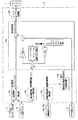
本発明の一実施形態の車両安定化制御システムについて説明する。図1は、本実施形態における車両安定化制御システムの概略構成を示したものである。なお、本実施形態では、車両の駆動形態が後輪駆動のものを想定して説明するが、勿論、前輪駆動の車両でも4輪駆動の車両でも本発明を適用することができる。
(First embodiment)
A vehicle stabilization control system according to an embodiment of the present invention will be described. FIG. 1 shows a schematic configuration of a vehicle stabilization control system in the present embodiment. In the present embodiment, the description will be made assuming that the driving mode of the vehicle is a rear wheel drive, but of course, the present invention can be applied to a front wheel drive vehicle or a four wheel drive vehicle.
本実施形態の車両安定化制御システムは、車両に備えられたエンジン1が発生させる駆動トルクを調整し、ピッチング振動エネルギー等に起因する前後輪荷重の変動に基づくコーナリングパワーの変動を安定化させることで、車体の姿勢や車両特性を安定化するものである。
The vehicle stabilization control system of the present embodiment adjusts the driving torque generated by the
図1に示す車両安定化制御システムにおいて、エンジン1は、エンジンECU2によって制御されるようになっている。このエンジンECU2には、アクセルストロークセンサ3、エンジン回転センサ4、前輪用車輪速度センサ5a、5b、ギア位置センサ6からの検出信号が入力されるようになっている。
In the vehicle stabilization control system shown in FIG. 1, the
アクセルストロークセンサ3は、アクセルペダル7の操作量に応じた検出信号を出力するものである。エンジンECU2では、このアクセルストロークセンサ3からの検出信号に基づいてアクセル操作量が求められるようになっている。
The
エンジン回転センサ4は、エンジン1に設置されている周知のもので、エンジン回転速度に応じた検出信号を出力するようになっている。
The
このエンジン回転センサ4からの検出信号と、上述したアクセルストロークセンサ3からの検出信号から求められるアクセル操作量とから、エンジンECU2では、ドライバが要求するエンジントルクとなる基本要求エンジントルクが算出されるようになっている。
From the detection signal from the
前輪用車輪速度センサ5a、5bは、操舵輪となる両前輪10a、10bそれぞれに対応して備えられており、右前輪用の車輪速度センサ5aと左前輪用の車輪速度センサ5bとによって構成されている。これら各車輪速度センサ5a、5bは、例えば、車軸に備えられた歯車型のロータの歯の回転に応じて異なる検出信号を出力する電磁ピックアップタイプ等の周知のもので構成され、各前輪の回転に応じた検出信号を発生させる。この前輪用車輪速度センサ5a、5bからの検出信号は、前輪車輪速度に応じて発生する前輪走行抵抗外乱を求めるために用いられる。
The front
ギア位置センサ6は、現在設定されているギアの位置を検出するためのものである。このギア位置センサ6での検出信号がエンジンECU2に入力されるようになっており、エンジンECU2にて、入力された検出信号から現在設定されているギア位置に応じたギア比が求められるようになっている。
The
そして、エンジンECU2では、これら各センサ3、4、5a、5b、6からの検出信号に基づき、種々の演算を行い、その演算結果に基づいてエンジンパワーを調整する。これにより、トランスミッション11、終減速装置12および駆動軸13を介して駆動輪となる後輪14a、14bに伝えられる車軸トルクが調整されるようになっている。
The
図2に、このエンジンECU2のブロック構成を概略的に示し、この図を参照してエンジンECU2の詳細について説明する。
FIG. 2 schematically shows a block configuration of the
エンジンECU2は、CPU、RAM、ROM、I/Oなどを備えたマイクロコンピュータによって構成されている。そして、CPUにてROMに記憶されたエンジン制御プログラムを実行し、各種演算を行うことで、エンジン1によるエンジンパワーの制御を実行するようになっている。
The
具体的には、エンジンECU2は、図2に示されるように、基本要求エンジントルク算出部2a、推定駆動軸トルク算出部2b、前輪車輪速度算出部2c、前輪走行抵抗外乱推定部2d、要求エンジントルク補正部2e、エンジントルクベース制御部2fを備えて構成されている。
Specifically, as shown in FIG. 2, the
基本要求エンジントルク算出部2aは、ペダルストロークセンサ3から出力される検出信号を受け取り、それらの検出信号に基づいてアクセル操作量を物理量として求めると共に、その操作量とエンジン回転数センサ4から出力される検出信号とに基づいて基本要求駆動力に相当する基本要求エンジントルクを求めるものである。ここで求められた基本要求エンジントルクが車両の加速、減速に使用されるトルク、つまり基本的に要求されるエンジン軸トルクとなるものである。そして、この基本要求エンジントルク演算部2aでの演算結果が要求エンジントルク補正部2eに出力されるようになっている。
The basic required engine
推定駆動軸トルク算出部2bは、エンジン回転数センサ4からの検出信号に基づき、そのときの推定駆動軸トルク、すなわち検出信号を得たときに発生させられているであろう駆動軸トルクを演算する。この推定駆動軸トルク算出部2bでの演算結果も要求エンジントルク補正部2eに出力されるようになっている。
Based on the detection signal from the
前輪車輪速度算出部2cは、両車輪速度センサ5a、5bからの検出信号に基づいて操舵輪となる両前輪の車輪速度を算出するものである。この前輪車輪速度算出部2cが前輪走行抵抗外乱推定部2dに出力されるようになっている。
The front
前輪走行抵抗外乱推定部2dは、演算された前輪車輪速度に基づき、前輪走行抵抗外乱を推定する。前輪には車輪速度に応じた走行抵抗が発生する。このため、その走行抵抗外乱を車輪速度から推定するのである。例えば、車輪速度の微分値に対して車両重量を掛けることで並進方向の力[N/m]を求め、それに更に転動輪の半径を乗算することにより、走行抵抗外乱を転動輪に働くモーメント[N]として求めることが可能となる。
The front wheel running resistance
このような車輪速度の一回微分に基づいて走行抵抗外乱を求めることで、その走行抵抗外乱の要因が何であったかに関係なく、結果としてどれだけの走行抵抗外乱が入ったかを求めることが可能となる。すなわち、走行抵抗外乱は、例えば、ドライバによる操舵により発生したコーナリングドラッグによって生じたり、路面の凹凸によって生じたりするが、どのような場合であっても、結果的に車輪速度に変化が生じることから、その車輪速度の変化(微分値)から走行抵抗外乱を算出すれば、どのような要因かに関わらず、転動輪が受けた走行抵抗外乱を求めることができる。 By determining the running resistance disturbance based on such a single differentiation of the wheel speed, it is possible to determine how much running resistance disturbance has entered as a result, regardless of what caused the running resistance disturbance. Become. That is, the running resistance disturbance is caused by, for example, cornering drag generated by steering by the driver or by road surface unevenness, but in any case, the wheel speed changes as a result. If the running resistance disturbance is calculated from the change (differential value) of the wheel speed, the running resistance disturbance received by the rolling wheels can be obtained regardless of the cause.
なお、この走行抵抗外乱に関しては、車輪速度と走行抵抗外乱との特性をエンジンECU2内のメモリなどに予め記憶させておき、その特性に基づいて演算された車輪速度と対応する走行抵抗外乱を選択することによって、推定することも可能である。
As for the running resistance disturbance, the characteristics of the wheel speed and the running resistance disturbance are stored in advance in a memory in the
要求エンジントルク補正部2eは、推定駆動軸トルク算出部2bによって算出された推定駆動軸トルクと前輪走行抵抗外乱推定部2dで求められた走行抵抗外乱とを足し合わせたものを現在の駆動トルクとして推定する。そして、要求エンジントルク補正部2eは、その現在の駆動トルクを入力として、車体バネ上振動モデルの状態方程式よりピッチング振動を抑制するために必要とされる補正値を求め、その補正値に基づいて基本要求エンジントルク算出部2bで演算された基本要求エンジントルクを補正する。
The requested engine
具体的には、現在の駆動トルクが推定されると、上述した数式18、数式19で示される状態方程式に基づいて、現在の駆動トルクに対する駆動トルク反力を加振源とする各種車体バネ上振動の各状態量を推定できる。そして、本実施形態の場合には、推定された各状態量を数式20で示されるピッチング振動の出力方程式に代入することで、ピッチング振動を求め、このピッチング振動を抑えられる補正値を求める。
Specifically, when the current driving torque is estimated, on the various body spring springs using the driving torque reaction force with respect to the current driving torque as an excitation source based on the state equations represented by the above-described Expressions 18 and 19. Each state quantity of vibration can be estimated. In the case of the present embodiment, the estimated state quantities are substituted into the output equation of the pitching vibration expressed by
すなわち、図2に示されるように、車体振動モデルから推定駆動トルクに相応するピッチング振動の変動成分を示す出力y(=x8)を求め、この出力yに対して所定の状態フィードバックゲインKsを乗じることで補正値が求められる。なお、ここでいう状態フィードバックゲインKsとは、K1〜K8という状態量の数に応じて設定されるもので、車体振動モデルを用いて演算した各状態量x(x、x’、xtf、xtf’、xtr、xtr’、θp、θp’)に対して最適レギュレータ設計手法によって求めたものである。 That is, as shown in FIG. 2, an output y (= x8) indicating a fluctuation component of pitching vibration corresponding to the estimated driving torque is obtained from the vehicle body vibration model, and this output y is multiplied by a predetermined state feedback gain Ks. Thus, a correction value is obtained. The state feedback gain Ks here is set according to the number of state quantities K1 to K8, and each state quantity x (x, x ′, xtf, xtf) calculated using the vehicle body vibration model. ', Xtr, xtr', θp, θp ') are obtained by the optimum regulator design method.
このようにして求められた補正値に対して、終減速装置12での減速比(ディファレンシャル比:1/Rd)を掛けたのち、さらに、ギア位置センサ6の検出信号に基づいて求められるトランスミッション11におけるギア比で割られる。その値が基本要求トルク算出部2aで演算された基本要求トルクから減算される。
After multiplying the correction value obtained in this way by the reduction ratio (differential ratio: 1 / Rd) in the
これにより、エンジントルクの補正値が基本要求エンジントルクに対する絶対値として求められ、この値が補正後要求エンジントルクとされる。そして、この補正後要求エンジントルクがエンジントルクベース制御部2fに入力される。
Thereby, the correction value of the engine torque is obtained as an absolute value with respect to the basic required engine torque, and this value is set as the corrected required engine torque. Then, the post-correction required engine torque is input to the engine torque
エンジントルクベース制御部2fは、補正後要求エンジントルクが得られるように、エンジン1の吸入空気量、燃料噴射量および点火時期を設定し、それに応じた出力信号を発生させるものである。この出力信号がエンジン1内の各部に伝えられ、吸入空気量、燃料噴射量および点火時期が調整されることで、補正後要求エンジントルクが得られるようなエネルギーが出力される。
The engine torque
そして、このエネルギーがトランスミッション11および終減速装置12などを介して駆動輪14a、14bに回転エネルギーとして伝えられ、駆動輪14a、14bにて補正後要求エンジントルクに応じた車軸トルクを発生させるようになっている。
Then, this energy is transmitted as rotational energy to the
以上説明したように、本実施形態に示した車両安定化制御システムによれば、車体振動モデルにより車体バネ上の各種振動を推定し、車体バネ上の振動の1つであるピッチング振動を抑えるように、要求駆動力に相当する要求エンジントルクを補正している。 As described above, according to the vehicle stabilization control system shown in the present embodiment, various vibrations on the vehicle body spring are estimated by the vehicle body vibration model so as to suppress the pitching vibration that is one of the vibrations on the vehicle body spring. In addition, the required engine torque corresponding to the required driving force is corrected.
このため、時々刻々と変化する様々なドライバ操作外乱や路面外乱等の影響を抑圧するように、その時々にピッチング振動を抑え、車両内部の各状態量を安定化させることが可能となる。これにより、車両の走行状態を安定化させることが可能となる。 For this reason, it is possible to suppress pitching vibrations from time to time and to stabilize each state quantity inside the vehicle so as to suppress the influence of various driver operation disturbances and road surface disturbances that change every moment. As a result, the traveling state of the vehicle can be stabilized.
参考として、図3に、駆動トルクの変化に対するピッチング角速度の変化についてシミュレーションした結果を示す。この図に示されるように、本実施形態による制御を行った場合は、制御を行っていない場合と比べて、ピッチング角速度の振幅が少なく、早期に安定化していることが分かる。 As a reference, FIG. 3 shows the result of a simulation of the change in pitching angular velocity with respect to the change in drive torque. As shown in this figure, it can be seen that when the control according to the present embodiment is performed, the amplitude of the pitching angular velocity is small compared with the case where the control is not performed, and is stabilized early.
したがって、ドライバ操作外乱や路面外乱等に起因する車体挙動の変動が車体姿勢や車両特性を損なわせることを防止でき、車両の乗り心地や走行安定性を向上させることが可能となる。 Therefore, it is possible to prevent fluctuations in vehicle body behavior caused by driver operation disturbance, road surface disturbance, and the like from damaging the vehicle body posture and vehicle characteristics, and it is possible to improve the riding comfort and running stability of the vehicle.
(第2実施形態)
本発明の第2実施形態について説明する。上記第1実施形態では、ピッチング振動を抑制するために、ピッチング振動の変動成分が速やかに0となるような補正値を求めた。これに対し、本実施形態では、前輪接地荷重の変動を抑制すべく、前輪接地荷重の変動分の微分項ΔWfdを速やかに0にするものである。なお、本実施形態における車両安定化制御システムの構成に関しては第1実施形態で示した図1、図2と同様であるため、ここでは第1実施形態と異なる部分についてのみ説明する。
(Second Embodiment)
A second embodiment of the present invention will be described. In the first embodiment, in order to suppress the pitching vibration, a correction value is obtained so that the fluctuation component of the pitching vibration becomes 0 quickly. In contrast, in the present embodiment, the differential term ΔWfd corresponding to the fluctuation of the front wheel ground load is quickly set to 0 in order to suppress the fluctuation of the front wheel ground load. Note that the configuration of the vehicle stabilization control system in the present embodiment is the same as that in FIGS. 1 and 2 shown in the first embodiment, and therefore only the parts different from the first embodiment will be described here.
本実施形態の車両安定化制御システムは、要求エンジントルク補正部2eの処理についてのみ第1実施形態と異なる。すなわち、本実施形態の車両安定化制御システムでは、要求エンジントルク補正部2eにおいて、第1実施形態と同様の手法によって現在の駆動トルクを求めたのち、これを入力として、車体バネ上振動モデルの状態方程式より前輪接地荷重の変動を抑制するために必要とされる補正値を求め、その補正値に基づいて基本要求エンジン算出部2bで演算された基本要求エンジントルクを補正する。
The vehicle stabilization control system of the present embodiment differs from the first embodiment only in the processing of the required engine
具体的には、現在の駆動トルクが推定されると、上述した数式18、数式19で示される状態方程式に基づいて、現在の駆動トルクに対する駆動トルク反力を加振源とする各種車体バネ上振動の各状態量を推定できる。そして、本実施形態の場合には、推定された各状態量を数式25で示される前輪接地荷重の変動分の微分項ΔWfdの出力方程式に代入することで、前輪接地荷重の変動分の微分項ΔWfdを求め、これを抑えられる補正値を求める。 Specifically, when the current driving torque is estimated, on the various body spring springs using the driving torque reaction force with respect to the current driving torque as an excitation source based on the state equations represented by the above-described Expressions 18 and 19. Each state quantity of vibration can be estimated. In the case of this embodiment, by substituting each estimated state quantity into the output equation of the differential term ΔWfd for the fluctuation of the front wheel grounding load expressed by Formula 25, the differential term for the fluctuation of the front wheel grounding load is obtained. ΔWfd is obtained, and a correction value that can suppress this is obtained.
この補正値の求め方に関しては第1実施形態と同様であり、この補正値が終減速装置12での減速比で乗算された後、トランスミッション11のギア比で割算され、その値が基本要求トルク算出部2aで演算された基本要求トルクから減算される。
The correction value is obtained in the same manner as in the first embodiment. This correction value is multiplied by the reduction ratio in the
これにより、エンジントルクの補正値が基本要求エンジントルクに対する絶対値として求められ、この値が補正後要求エンジントルクとされる。 Thereby, the correction value of the engine torque is obtained as an absolute value with respect to the basic required engine torque, and this value is set as the corrected required engine torque.
以上説明したように、本実施形態に示した車両安定化制御システムによれば、車体振動モデルにより車体バネ上の各種振動を推定し、前輪接地荷重の変動を抑えるように、要求駆動力に相当する要求エンジントルクを補正している。 As described above, according to the vehicle stabilization control system shown in the present embodiment, various vibrations on the vehicle body spring are estimated based on the vehicle body vibration model, which corresponds to the required driving force so as to suppress fluctuations in the front wheel ground load. The requested engine torque is corrected.
このため、時々刻々と変化する様々なドライバ操作外乱や路面外乱等の影響を抑圧し、その時々に前輪接地荷重の変動を抑え、車両内部の各状態量を安定化させることが可能となる。これにより、車両の走行状態を安定化させることが可能となる。 For this reason, it is possible to suppress the effects of various driver operation disturbances and road surface disturbances that change from moment to moment, suppress fluctuations in the front wheel ground load at each time, and stabilize each state quantity in the vehicle. As a result, the traveling state of the vehicle can be stabilized.
参考として、図4に、駆動トルクの変化に対する前輪接地荷重の変化率の変化についてシミュレーションした結果を示す。この図に示されるように、本実施形態による制御を行った場合は、制御を行っていない場合と比べて、前輪接地荷重の変化率の振幅が少なく、早期に安定化していることが分かる。 As a reference, FIG. 4 shows the result of simulation of the change in the change rate of the front wheel ground load with respect to the change in drive torque. As shown in this figure, it can be seen that when the control according to the present embodiment is performed, the amplitude of the change rate of the front wheel ground load is small and stabilized early compared to the case where the control is not performed.
したがって、ドライバ操作外乱や路面外乱等に起因する車体挙動の変動が車体姿勢や車両特性を損なわせることを防止でき、車両の乗り心地や走行安定性を向上させることが可能となる。 Therefore, it is possible to prevent fluctuations in vehicle body behavior caused by driver operation disturbance, road surface disturbance, and the like from damaging the vehicle body posture and vehicle characteristics, and it is possible to improve the riding comfort and running stability of the vehicle.
(第3実施形態)
本発明の第3実施形態について説明する。上記第2実施形態では、前輪接地荷重の変動を抑制するものであったが、本実施形態では、後輪接地荷重の変動を抑制すべく、後輪接地荷重の変動分の微分項ΔWfdを速やかに0にする。なお、本実施形態における車両安定化制御システムの構成に関しても第1実施形態で示した図1、図2と同様であるため、ここでは第1実施形態と異なる部分についてのみ説明する。
(Third embodiment)
A third embodiment of the present invention will be described. In the second embodiment, the fluctuation of the front wheel ground load is suppressed. However, in this embodiment, the differential term ΔWfd corresponding to the fluctuation of the rear wheel ground load is quickly set to suppress the fluctuation of the rear wheel ground load. Set to 0. The configuration of the vehicle stabilization control system in the present embodiment is also the same as that shown in FIGS. 1 and 2 shown in the first embodiment, and therefore only the parts different from the first embodiment will be described here.
本実施形態の車両安定化制御システムは、要求エンジントルク補正部2eの処理についてのみ第1実施形態と異なる。すなわち、本実施形態の車両安定化制御システムでは、要求エンジントルク補正部2eにおいて、第1実施形態と同様の手法によって現在の駆動トルクを求めたのち、これを入力として、車体バネ上振動モデルの状態方程式より後輪接地荷重の変動を抑制するために必要とされる補正値を求め、その補正値に基づいて基本要求エンジン算出部2bで演算された基本要求エンジントルクを補正する。
The vehicle stabilization control system of the present embodiment differs from the first embodiment only in the processing of the required engine
具体的には、現在の駆動トルクが推定されると、上述した数式18、数式19で示される状態方程式に基づいて、現在の駆動トルクに対する駆動トルク反力を加振源とする各種車体バネ上振動の各状態量を推定できる。そして、本実施形態の場合には、推定された各状態量を数式26で示される後輪接地荷重の変動分の微分項ΔWrdの出力方程式に代入することで、後輪接地荷重の変動分の微分項ΔWrdを求め、これを抑えられる補正値を求める。 Specifically, when the current driving torque is estimated, on the various body spring springs using the driving torque reaction force with respect to the current driving torque as an excitation source based on the state equations represented by the above-described Expressions 18 and 19. Each state quantity of vibration can be estimated. In the case of the present embodiment, by substituting each estimated state quantity into the output equation of the differential term ΔWrd of the variation of the rear wheel ground load expressed by Equation 26, the variation of the rear wheel ground load is calculated. A differential term ΔWrd is obtained, and a correction value that can suppress this is obtained.
この補正値の求め方に関しては第1実施形態と同様であり、この補正値が終減速装置12での減速比で乗算された後、トランスミッション11のギア比で割算され、その値が基本要求トルク算出部2aで演算された基本要求トルクから減算される。
The correction value is obtained in the same manner as in the first embodiment. This correction value is multiplied by the reduction ratio in the
これにより、エンジントルクの補正値が基本要求エンジントルクに対する絶対値として求められ、この値が補正後要求エンジントルクとされる。 Thereby, the correction value of the engine torque is obtained as an absolute value with respect to the basic required engine torque, and this value is set as the corrected required engine torque.
以上説明したように、本実施形態に示した車両安定化制御システムによれば、車体振動モデルにより車体バネ上の各種振動を推定し、後輪接地荷重の変動を抑えるように、要求駆動力に相当する要求エンジントルクを補正している。 As described above, according to the vehicle stabilization control system shown in the present embodiment, various vibrations on the vehicle body spring are estimated by the vehicle body vibration model, and the required driving force is reduced so as to suppress the fluctuation of the rear wheel ground load. The corresponding required engine torque is corrected.
このため、時々刻々と変化する様々なドライバ操作外乱や路面外乱等の影響を抑圧し、その時々に後輪接地荷重の変動を抑え、車両内部の各状態量を安定化させることが可能となる。これにより、車両の走行状態を安定化させることが可能となる。 For this reason, it is possible to suppress the effects of various driver operation disturbances and road surface disturbances that change from moment to moment, to suppress fluctuations in the rear wheel ground load at each time, and to stabilize each state quantity inside the vehicle. . As a result, the traveling state of the vehicle can be stabilized.
参考として、図5に、駆動トルクの変化に対する後輪接地荷重の変化率の変化についてシミュレーションした結果を示す。この図に示されるように、本実施形態による制御を行った場合は、制御を行っていない場合と比べて、後輪接地荷重の変化率の振幅が少なく、早期に安定化していることが分かる。 As a reference, FIG. 5 shows the result of a simulation of the change in the change rate of the rear wheel ground load with respect to the change in drive torque. As shown in this figure, it can be seen that when the control according to the present embodiment is performed, the amplitude of the rate of change of the rear wheel ground load is small compared with the case where the control is not performed, and is stabilized early. .
したがって、ドライバ操作外乱や路面外乱等に起因する車体挙動の変動が車体姿勢や車両特性を損なわせることを防止でき、車両の乗り心地や走行安定性を向上させることが可能となる。 Therefore, it is possible to prevent fluctuations in vehicle body behavior caused by driver operation disturbance, road surface disturbance, and the like from damaging the vehicle body posture and vehicle characteristics, and it is possible to improve the riding comfort and running stability of the vehicle.
(第4実施形態)
本発明の第4実施形態について説明する。本実施形態では、車体の鉛直方向の上下振動を抑制すべく、車体の鉛直方向の上下振動の変動成分を速やかに0にする。なお、本実施形態における車両安定化制御システムの構成に関しても、第1実施形態で示した図1、図2と同様であるため、ここでは第1実施形態と異なる部分についてのみ説明する。
(Fourth embodiment)
A fourth embodiment of the present invention will be described. In the present embodiment, in order to suppress vertical vibration of the vehicle body in the vertical direction, the fluctuation component of vertical vibration of the vehicle body is quickly set to zero. The configuration of the vehicle stabilization control system in the present embodiment is also the same as that in FIGS. 1 and 2 shown in the first embodiment, and therefore only the parts different from the first embodiment will be described here.
本実施形態の車両安定化制御システムは、要求エンジントルク補正部2eの処理についてのみ第1実施形態と異なる。すなわち、本実施形態の車両安定化制御システムでは、要求エンジントルク補正部2eにおいて、第1実施形態と同様の手法によって現在の駆動トルクを求めたのち、これを入力として、車体バネ上振動モデルの状態方程式より車体の鉛直方向の上下運動の変動を抑制するために必要とされる補正値を求め、その補正値に基づいて基本要求エンジン算出部2bで演算された基本要求エンジントルクを補正する。
The vehicle stabilization control system of the present embodiment differs from the first embodiment only in the processing of the required engine
具体的には、現在の駆動トルクが推定されると、上述した数式18、数式19で示される状態方程式に基づいて、現在の駆動トルクに対する駆動トルク反力を加振源とする各種車体バネ上振動の各状態量を推定できる。そして、本実施形態の場合には、推定された各状態量を数式27で示される車体の鉛直方向の上下運動の変動成分x’(=x2)の出力方程式に代入することで、車体の鉛直方向の上下運動の変動成分を求め、これを抑えられる補正値を求める。 Specifically, when the current driving torque is estimated, on the various body spring springs using the driving torque reaction force with respect to the current driving torque as an excitation source based on the state equations represented by the above-described Expressions 18 and 19. Each state quantity of vibration can be estimated. In the case of the present embodiment, the estimated state quantities are substituted into the output equation of the fluctuation component x ′ (= x2) of the vertical movement of the vehicle body expressed by Equation 27, thereby obtaining the vehicle body vertical direction. The fluctuation component of the vertical movement in the direction is obtained, and a correction value that can suppress this is obtained.
この補正値の求め方に関しては第1実施形態と同様であり、この補正値が終減速装置12での減速比で乗算された後、トランスミッション11のギア比で割算され、その値が基本要求トルク算出部2aで演算された基本要求トルクから減算される。
The correction value is obtained in the same manner as in the first embodiment. This correction value is multiplied by the reduction ratio in the
これにより、エンジントルクの補正値が基本要求エンジントルクに対する絶対値として求められ、この値が補正後要求エンジントルクとされる。 Thereby, the correction value of the engine torque is obtained as an absolute value with respect to the basic required engine torque, and this value is set as the corrected required engine torque.
以上説明したように、本実施形態に示した車両安定化制御システムによれば、車体振動モデルにより車体バネ上の各種振動を推定し、車体の鉛直方向の上下運動の変動を抑えるように、要求駆動力に相当する要求エンジントルクを補正している。 As described above, according to the vehicle stabilization control system shown in the present embodiment, various vibrations on the vehicle body spring are estimated by the vehicle body vibration model, and a request is made to suppress fluctuations in the vertical movement of the vehicle body in the vertical direction. The required engine torque corresponding to the driving force is corrected.
このため、時々刻々と変化する様々なドライバ操作外乱や路面外乱等の影響を抑圧し、その時々に車体の鉛直方向の上下運動の変動を抑えることができる。これにより、あたかも車両が上から押さえ付けられているように、車両内部の各状態量を安定化させることが可能となり、車両の走行状態を安定化させることが可能となる。 For this reason, it is possible to suppress the influence of various driver operation disturbances and road surface disturbances that change from moment to moment, and to suppress fluctuations in the vertical movement of the vehicle body at that time. As a result, it is possible to stabilize each state quantity inside the vehicle as if the vehicle is pressed from above, and it is possible to stabilize the running state of the vehicle.
参考として、図6に、駆動トルクの変化に対する車体の鉛直方向の上下変位の変化率の変化についてシミュレーションした結果を示す。この図に示されるように、本実施形態による制御を行った場合は、制御を行っていない場合と比べて、車体の鉛直方向の上下変位の変化率の振幅が少なく、早期に安定化していることが分かる。 As a reference, FIG. 6 shows the result of a simulation of the change in the rate of change of the vertical displacement of the vehicle body in the vertical direction with respect to the change in drive torque. As shown in this figure, when the control according to the present embodiment is performed, the amplitude of the change rate of the vertical displacement of the vehicle body in the vertical direction is small compared with the case where the control is not performed, and is stabilized at an early stage. I understand that.
したがって、ドライバ操作外乱や路面外乱等に起因する車体挙動の変動が車体姿勢や車両特性を損なわせることを防止でき、車両の乗り心地や走行安定性を向上させることが可能となる。 Therefore, it is possible to prevent fluctuations in vehicle body behavior caused by driver operation disturbance, road surface disturbance, and the like from damaging the vehicle body posture and vehicle characteristics, and it is possible to improve the riding comfort and running stability of the vehicle.
(他の実施形態)
(1)上記各実施形態では、エンジントルクベースの制御形態として説明を行ったが、これは駆動力を規定するパラメータの一例を示したものであり、必ずしもエンジントルクベースとしなければならない訳ではない。
(Other embodiments)
(1) In the above embodiments, the engine torque base control mode has been described. However, this is an example of a parameter that defines the driving force, and the engine torque base is not necessarily required. .
例えば、車軸トルクベースの制御形態とすることも可能である。この場合、図7に示されるように、エンジンECU2に関して、基本要求エンジントルク算出部2aが基本要求出力軸トルク算出部2a’に代えられると共に、要求エンジントルク補正部2eが要求出力軸トルク補正部2e’に変えられる。そして、この基本要求出力軸算出部2a’によって求められる基本要求出力軸トルクを補正するための補正値が要求出力軸トルク補正部2e’によって求められ、要求出力軸トルクから補正値に終減速装置12の減速比を掛けたものが減算されることで、補正後要求出力軸トルクが求められる。このように、駆動力を規定する他のパラメータを用いることも可能である。
For example, it is possible to adopt an axle torque-based control mode. In this case, as shown in FIG. 7, with respect to the
なお、この場合には、上記各実施形態のようなエンジントルクベース制御部2f(図2参照)の前段にパワートレインコーディネータ2gが配置され、エンジントルクベース制御部2fと並列的にトランスミッション制御部2hが設けられる。このような構成においては、パワートレインコーディネータ2gによって、補正後要求出力軸トルクに基づいて要求エンジントルクを求めると共に、補正後要求出力軸トルクおよび車速に基づいて要求変速費および要求L/Uが求められる。そして、要求エンジントルクが得られるように、エンジントルクベース制御部2fにて、スロットル開度、燃料噴射量および点火時期が設定され、要求変速比および要求L/Uが得られるように、トランスミッション制御部2hにて、トランスミッション11内のソレノイドへの通電テューティが設定されることになる。
In this case, a powertrain coordinator 2g is disposed in front of the engine torque
(2)また、上記実施形態において、要求駆動力の補正が必要とされる他の要因、例えば、トラクション制御や横滑り防止制御から要求駆動トルクの補正要求があった場合には、それを考慮して要求駆動力補正を行うことが可能である。この場合、要求駆動力として求められた基本要求エンジントルクをトラクション制御や横滑り防止制御の要求に応じて補正し、その値を車体バネ上振動を考慮した補正を行う前の基本要求エンジントルクと見なせば良い。 (2) In the above embodiment, if there is a request for correction of the required driving torque from other factors that require correction of the required driving force, for example, traction control or skid prevention control, take that into consideration. The required driving force can be corrected. In this case, the basic required engine torque obtained as the required driving force is corrected in accordance with the request for traction control or skid prevention control, and the value is regarded as the basic required engine torque before correction considering the vehicle body sprung vibration. What should I do?
(3)また、上記各実施形態では、状態フィードバックゲインKsが最適レギュレータ手法によって求められたものを例に挙げて説明したが、制御系の各種手法、例えば、極配置による設計であっても構わない。 (3) In each of the above embodiments, the state feedback gain Ks has been described by taking the optimum regulator technique as an example. However, various control system techniques, for example, design by pole arrangement may be used. Absent.
1…エンジン、2…エンジンECU、2a…基本要求エンジントルク算出部、2b…推定駆動軸トルク算出部、2c…前輪車輪速度算出部、2d…前輪走行抵抗外乱推定部、2e…要求エンジントルク補正部、2f…エンジントルクベース制御部、2g…パワートレインコーディネータ、2h…トランスミッション制御部、3…アクセルストロークセンサ、4…エンジン回転数センサ、5a、5b…車輪速度センサ、6…ギア位置センサ、10a、10b…前輪、14a、14b…後輪。
DESCRIPTION OF
Claims (3)
前記車両に発生させられていると推定される推定駆動力に相当する物理量を求める推定駆動力推定部(2b)と、
前記推定駆動力に相当する物理量に基づいて、前記推定駆動力が発生している場合に前記車両に発生し得る前輪接地荷重または後輪接地荷重の変動を求め、この前輪接地荷重または後輪接地荷重の変動の微分項(ΔWfd、ΔWrd)自体を小さくするための補正値を求めると共に、該補正値に基づいて、前記基本要求駆動力演算部(2a)が演算した前記基本要求駆動力に相当する物理量を補正することで、補正後要求駆動力を求める要求駆動力補正部(2e)と
を備え、
前記要求駆動力補正部(2e)は、前記車両におけるバネ上振動モデルに基づいて前記車両における状態量を示し、かつ、定数として、少なくともタイヤ縦弾性係数(Ktf、Ktr[N/m])およびタイヤ縦減衰係数(Ctf、Ctr[Ns/m])が含まれている状態方程式を有していると共に、前記状態方程式に基づいて前記前輪接地荷重または前記後輪接地荷重の変動の微分項(ΔWfd、ΔWrd)を前記状態量で表した出力方程式を有しており、前記出力方程式と前記状態量とから求められる前記前輪接地荷重または後輪接地荷重の変動の微分項(ΔWfd、ΔWrd)を小さくするように、前記基本要求駆動力に相当する前記物理量の補正を行うようになっており、
前記要求駆動力補正部(2e)が求めた補正後要求駆動力を前記駆動輪に発生させるようになっていることを特徴とする車両安定化制御システム。 A basic required driving force calculation unit (2a) for calculating a physical quantity corresponding to the basic required driving force in order to generate a basic required driving force required by the driver for the driving wheels provided in the vehicle;
An estimated driving force estimation unit (2b) for obtaining a physical quantity corresponding to the estimated driving force estimated to be generated in the vehicle;
Based on a physical quantity corresponding to the estimated driving force, a change in the front wheel ground load or the rear wheel ground load that may occur in the vehicle when the estimated driving force is generated is obtained, and the front wheel ground load or the rear wheel ground contact is determined. A correction value for reducing the differential terms (ΔWfd, ΔWrd) itself of the fluctuation of the load is obtained, and based on the correction value, it corresponds to the basic required driving force calculated by the basic required driving force calculation unit (2a). A required driving force correction unit (2e) for calculating a corrected required driving force by correcting the physical quantity to be
The required driving force correction unit (2e) indicates a state quantity in the vehicle based on a sprung vibration model in the vehicle, and as a constant, at least a tire longitudinal elastic modulus (Ktf, Ktr [N / m]) and A state equation including a tire longitudinal damping coefficient (Ctf, Ctr [Ns / m]), and a differential term of variation of the front wheel ground load or the rear wheel ground load based on the state equation ( ΔWfd, ΔWrd) has an output equation representing the state quantity, and differential terms (ΔWfd, ΔWrd) of fluctuations of the front wheel ground load or the rear wheel ground load obtained from the output equation and the state quantity are obtained. The physical quantity corresponding to the basic required driving force is corrected so as to be small,
The vehicle stabilization control system is characterized in that the required driving force after correction obtained by the required driving force correction unit (2e) is generated in the driving wheel.
前記要求駆動力補正部(2e)は、前記推定駆動力算出部(2b)が求めた前記推定駆動力に相当する物理量に対して、前記走行抵抗外乱推定部によって推定される走行抵抗外乱を加算した値を現在発生している駆動力と推定し、前記補正値として、この走行抵抗外乱を鑑みた駆動力が発生しているときの補正値を求めるようになっていることを特徴とする請求項1または2に記載の車両安定化制御システム。 A running resistance disturbance estimator (2d) for estimating running resistance disturbance applied to wheels in the vehicle;
The required driving force correction unit (2e) adds a running resistance disturbance estimated by the running resistance disturbance estimation unit to a physical quantity corresponding to the estimated driving force obtained by the estimated driving force calculation unit (2b). The calculated value is estimated as the currently generated driving force, and the correction value when the driving force is generated in consideration of the running resistance disturbance is obtained as the correction value. Item 3. The vehicle stabilization control system according to Item 1 or 2.
Priority Applications (6)
| Application Number | Priority Date | Filing Date | Title |
|---|---|---|---|
| JP2004258335A JP4515201B2 (en) | 2004-09-06 | 2004-09-06 | Vehicle stabilization control system |
| US11/214,643 US7599763B2 (en) | 2004-09-06 | 2005-08-30 | Vehicle stability control system |
| DE602005003078T DE602005003078T2 (en) | 2004-09-06 | 2005-09-01 | Stabilization system for motor vehicles with compensation of fluctuations in the driving resistance |
| EP05019046A EP1632382B1 (en) | 2004-09-06 | 2005-09-01 | Vehicle stability control system with running resistance fluctuation compensation |
| CNB2005101036209A CN100441437C (en) | 2004-09-06 | 2005-09-06 | Vehicle stability control system |
| US11/274,766 US7630796B2 (en) | 2004-09-06 | 2005-11-15 | Body action information system |
Applications Claiming Priority (1)
| Application Number | Priority Date | Filing Date | Title |
|---|---|---|---|
| JP2004258335A JP4515201B2 (en) | 2004-09-06 | 2004-09-06 | Vehicle stabilization control system |
Publications (2)
| Publication Number | Publication Date |
|---|---|
| JP2006069472A JP2006069472A (en) | 2006-03-16 |
| JP4515201B2 true JP4515201B2 (en) | 2010-07-28 |
Family
ID=35197670
Family Applications (1)
| Application Number | Title | Priority Date | Filing Date |
|---|---|---|---|
| JP2004258335A Expired - Fee Related JP4515201B2 (en) | 2004-09-06 | 2004-09-06 | Vehicle stabilization control system |
Country Status (5)
| Country | Link |
|---|---|
| US (1) | US7599763B2 (en) |
| EP (1) | EP1632382B1 (en) |
| JP (1) | JP4515201B2 (en) |
| CN (1) | CN100441437C (en) |
| DE (1) | DE602005003078T2 (en) |
Families Citing this family (68)
| Publication number | Priority date | Publication date | Assignee | Title |
|---|---|---|---|---|
| JP4172391B2 (en) * | 2003-12-24 | 2008-10-29 | 株式会社デンソー | Vehicle integrated control system and program |
| US9188167B2 (en) | 2006-02-22 | 2015-11-17 | Schaeffler Technologies AG & Co. KG | Clutch housing with lever spring retention slots and method of installing a lever spring |
| DE112007002097A5 (en) * | 2006-09-28 | 2009-06-18 | Luk Lamellen Und Kupplungsbau Beteiligungs Kg | powertrain |
| JP4692499B2 (en) * | 2007-02-28 | 2011-06-01 | トヨタ自動車株式会社 | Vehicle vibration suppression control device |
| JP4600381B2 (en) * | 2006-10-19 | 2010-12-15 | トヨタ自動車株式会社 | Vehicle wheel torque estimation device and vibration suppression control device |
| CN102582388B (en) | 2006-10-19 | 2014-07-09 | 丰田自动车株式会社 | Vibration-damping control device for vehicle |
| JP4844407B2 (en) * | 2007-01-25 | 2011-12-28 | トヨタ自動車株式会社 | Traveling device |
| JP4396717B2 (en) | 2007-03-07 | 2010-01-13 | トヨタ自動車株式会社 | Vehicle control apparatus, control method, program for realizing the method, and recording medium recording the program |
| JP4910794B2 (en) * | 2007-03-12 | 2012-04-04 | トヨタ自動車株式会社 | Drive control device for controlling vibration control of vehicle |
| JP4835480B2 (en) * | 2007-03-19 | 2011-12-14 | トヨタ自動車株式会社 | Vehicle vibration suppression control device |
| JP4867735B2 (en) * | 2007-03-20 | 2012-02-01 | トヨタ自動車株式会社 | Drive control device for controlling vibration control of vehicle |
| JP5061764B2 (en) * | 2007-07-10 | 2012-10-31 | トヨタ自動車株式会社 | Vehicle vibration suppression control device |
| ITBO20070598A1 (en) | 2007-08-31 | 2009-03-01 | Ferrari Spa | METHOD OF CONTROL OF THE POSITIONING ANGLE OF A REAR TRACTION VEHICLE DURING THE TRAVEL OF A CURVE |
| US7997363B2 (en) * | 2007-09-17 | 2011-08-16 | Denso Corporation | Vehicle control system and method |
| US8140238B2 (en) * | 2007-10-26 | 2012-03-20 | Ford Global Technologies, Llc | Detection and control of power induced hop during traction control in a vehicle |
| US7853389B2 (en) * | 2007-10-29 | 2010-12-14 | Ford Global Technologies, Llc | Traction control for performance and demonstration spin |
| US8244445B2 (en) * | 2007-10-30 | 2012-08-14 | Ford Global Technologies, Llc | Stuck vehicle with time and pedal related traction control |
| JP4941235B2 (en) * | 2007-10-31 | 2012-05-30 | トヨタ自動車株式会社 | Drive control device for damping control of diesel engine vehicle |
| JP4872884B2 (en) * | 2007-11-01 | 2012-02-08 | トヨタ自動車株式会社 | Diesel engine vehicle vibration control system |
| JP5056367B2 (en) * | 2007-11-20 | 2012-10-24 | トヨタ自動車株式会社 | Vehicle vibration suppression control device |
| JP4650483B2 (en) * | 2007-12-12 | 2011-03-16 | 株式会社デンソー | Vehicle travel control device |
| JP5262811B2 (en) * | 2008-10-31 | 2013-08-14 | トヨタ自動車株式会社 | Vehicle sprung mass damping control device |
| JP5083174B2 (en) | 2008-10-31 | 2012-11-28 | トヨタ自動車株式会社 | Vehicle vibration suppression control device |
| WO2010050070A1 (en) * | 2008-10-31 | 2010-05-06 | トヨタ自動車株式会社 | Damping controller of vehicle |
| WO2010050069A1 (en) * | 2008-10-31 | 2010-05-06 | トヨタ自動車株式会社 | Driving force controller and controlling method of driving force controller |
| JP4938809B2 (en) * | 2009-01-27 | 2012-05-23 | 本田技研工業株式会社 | Vehicle driving force control device |
| JP4678444B2 (en) * | 2009-04-09 | 2011-04-27 | トヨタ自動車株式会社 | Vehicle control device |
| JP5444111B2 (en) | 2009-05-13 | 2014-03-19 | トヨタ自動車株式会社 | Vehicle sprung mass damping control device |
| EP2431217B1 (en) | 2009-05-13 | 2018-10-10 | Toyota Jidosha Kabushiki Kaisha | Damping control device |
| JP5347702B2 (en) * | 2009-05-13 | 2013-11-20 | トヨタ自動車株式会社 | Vehicle sprung mass damping control device |
| JP5287559B2 (en) * | 2009-07-09 | 2013-09-11 | トヨタ自動車株式会社 | Vehicle vibration control device |
| EP2451662B1 (en) | 2009-07-09 | 2013-09-11 | Toyota Jidosha Kabushiki Kaisha | Vehicular damping control system |
| WO2011039807A1 (en) | 2009-09-30 | 2011-04-07 | トヨタ自動車株式会社 | Damping control device |
| KR20110061601A (en) * | 2009-09-30 | 2011-06-09 | 가부시키가이샤 미마키 엔지니어링 | Program, image forming method, and printing system |
| WO2011042928A1 (en) | 2009-10-05 | 2011-04-14 | トヨタ自動車株式会社 | Vehicle vibration control device |
| CN102666257B (en) * | 2009-10-30 | 2014-08-06 | 三菱电机株式会社 | Electric power steering control device |
| JP5278373B2 (en) | 2010-02-03 | 2013-09-04 | トヨタ自動車株式会社 | Vehicle vibration suppression control device |
| JP5319587B2 (en) * | 2010-03-25 | 2013-10-16 | ニチユ三菱フォークリフト株式会社 | Industrial vehicle |
| JP5088393B2 (en) * | 2010-04-12 | 2012-12-05 | トヨタ自動車株式会社 | Vehicle vibration suppression control device |
| JP5099167B2 (en) * | 2010-04-12 | 2012-12-12 | トヨタ自動車株式会社 | Vehicle vibration suppression control device |
| JP5672869B2 (en) * | 2010-09-07 | 2015-02-18 | 日産自動車株式会社 | Vehicle system vibration control device |
| JP5724524B2 (en) * | 2011-03-29 | 2015-05-27 | 日産自動車株式会社 | Car body vibration control device and car body vibration control method |
| JP5724523B2 (en) * | 2011-03-29 | 2015-05-27 | 日産自動車株式会社 | Car body vibration control device and car body vibration control method |
| US8831819B2 (en) | 2011-04-14 | 2014-09-09 | Toyota Jidosha Kabushiki Kaisha | Abnormality determination device and method of longitudinal acceleration sensor |
| CN102883906B (en) * | 2011-04-26 | 2015-08-19 | 丰田自动车株式会社 | Controller of vehicle |
| EP2816211B1 (en) * | 2012-02-16 | 2018-04-04 | Nissan Motor Co., Ltd | Vehicle body vibration-damping control device |
| JP5858055B2 (en) * | 2012-02-16 | 2016-02-10 | 日産自動車株式会社 | Vehicle system vibration control device |
| US9283959B2 (en) * | 2012-02-24 | 2016-03-15 | Toyota Jidosha Kabushiki Kaisha | Vehicle behavior control apparatus |
| JP6010984B2 (en) * | 2012-04-06 | 2016-10-19 | 日産自動車株式会社 | Vehicle system vibration control device |
| JP5983000B2 (en) * | 2012-05-01 | 2016-08-31 | 日産自動車株式会社 | Vehicle system vibration control device |
| JP6036414B2 (en) * | 2013-03-08 | 2016-11-30 | 株式会社デンソー | Vehicle control device |
| CN105452041A (en) * | 2013-08-05 | 2016-03-30 | 丰田自动车株式会社 | Vehicle vibration suppression control device |
| JP5868919B2 (en) * | 2013-09-10 | 2016-02-24 | 富士重工業株式会社 | Control device for four-wheel drive vehicle |
| JP6273776B2 (en) * | 2013-11-01 | 2018-02-07 | スズキ株式会社 | Driving force limiter |
| JP2015105623A (en) * | 2013-11-29 | 2015-06-08 | トヨタ自動車株式会社 | Vehicle body vibration control device of vehicle |
| JP2015105041A (en) * | 2013-11-29 | 2015-06-08 | トヨタ自動車株式会社 | Vehicle body vibration control device of vehicle |
| JP6252456B2 (en) * | 2014-12-08 | 2017-12-27 | トヨタ自動車株式会社 | Vehicle control device |
| JP6274139B2 (en) * | 2015-03-21 | 2018-02-07 | トヨタ自動車株式会社 | Vehicle vibration suppression control device |
| JP6233608B2 (en) | 2015-10-13 | 2017-11-22 | トヨタ自動車株式会社 | Vehicle driving force control device |
| JP6233609B2 (en) | 2015-10-27 | 2017-11-22 | トヨタ自動車株式会社 | Vehicle driving force control device |
| JP6627829B2 (en) | 2017-07-20 | 2020-01-08 | トヨタ自動車株式会社 | Vehicle vibration control device |
| JP6822347B2 (en) * | 2017-08-22 | 2021-01-27 | トヨタ自動車株式会社 | Internal combustion engine control device |
| JP7144722B2 (en) * | 2018-06-22 | 2022-09-30 | マツダ株式会社 | Vehicle control method and vehicle system |
| JP7144723B2 (en) * | 2018-06-22 | 2022-09-30 | マツダ株式会社 | Vehicle control method and vehicle system |
| JP7109744B2 (en) * | 2019-01-30 | 2022-08-01 | マツダ株式会社 | vehicle system |
| JP7264005B2 (en) | 2019-10-18 | 2023-04-25 | トヨタ紡織株式会社 | Vehicle behavior notification device |
| JP2023001800A (en) * | 2021-06-21 | 2023-01-06 | 株式会社デンソー | Travel control device, travel control method, and travel control program |
| CN116691657B (en) * | 2023-08-07 | 2023-10-13 | 博世汽车部件(苏州)有限公司 | Vehicle steering assist system, control unit thereof, and control method thereof |
Family Cites Families (21)
| Publication number | Priority date | Publication date | Assignee | Title |
|---|---|---|---|---|
| DE4014561A1 (en) | 1990-05-04 | 1991-11-07 | Teves Gmbh Alfred | CONTROL SYSTEM FOR MOTOR VEHICLES |
| JP3533685B2 (en) | 1993-10-04 | 2004-05-31 | セイコーエプソン株式会社 | Vehicle image data calculation device and control method therefor |
| JP3241549B2 (en) * | 1994-11-07 | 2001-12-25 | トヨタ自動車株式会社 | Acceleration sensor device for vehicle |
| GB2297952B (en) | 1995-02-14 | 1997-09-03 | Unisia Jecs Corp | Automotive vehicle suspension control system |
| JP3277244B2 (en) * | 1995-02-14 | 2002-04-22 | 株式会社ユニシアジェックス | Vehicle suspension system |
| JPH09249016A (en) | 1996-03-15 | 1997-09-22 | Unisia Jecs Corp | Vehicle suspension device |
| JPH10264839A (en) | 1997-03-25 | 1998-10-06 | Nissan Motor Co Ltd | Automatic parking device |
| DE19734112B4 (en) | 1997-08-07 | 2007-12-27 | Robert Bosch Gmbh | Method and device for traction control in motor vehicles |
| JP2001168599A (en) | 1999-12-06 | 2001-06-22 | Matsushita Electric Ind Co Ltd | Electronic-component mounting machine |
| JP2001231109A (en) | 2000-02-17 | 2001-08-24 | Toyota Motor Corp | Driving condition notifying device and fuel-cell mounted vehicle provided therewith |
| CA2423200A1 (en) | 2000-09-21 | 2002-03-28 | American Calcar Inc. | Technique for operating a vehicle effectively and safely |
| JP4419331B2 (en) | 2001-02-02 | 2010-02-24 | 株式会社デンソー | Vehicle travel control device |
| JP3881197B2 (en) | 2001-06-27 | 2007-02-14 | 株式会社デンソー | Vehicle automatic driving system |
| US6683539B2 (en) | 2001-12-27 | 2004-01-27 | Koninklijke Philips Electronics N.V. | Computer vision based parking assistant |
| WO2003076228A1 (en) | 2002-03-13 | 2003-09-18 | Daimlerchrysler Ag | Device for making available parameters |
| US20050273209A1 (en) | 2002-03-13 | 2005-12-08 | Daimlerchrysler Ag | Device for making available parameters |
| GB0210082D0 (en) | 2002-05-02 | 2002-06-12 | Ford Global Tech Inc | Vehicle differential control |
| US6976935B2 (en) | 2002-07-12 | 2005-12-20 | Luk Lamellen Und Kupplungsbau Beteiligungs Kg | Method and apparatus for operating a motor vehicle |
| JP4356305B2 (en) * | 2002-11-19 | 2009-11-04 | 株式会社デンソー | Vehicle control device |
| JP4161923B2 (en) * | 2004-03-09 | 2008-10-08 | 株式会社デンソー | Vehicle stabilization control system |
| US7894971B2 (en) * | 2005-12-28 | 2011-02-22 | Toyota Jidosha Kabushiki Kaisha | Vehicle control apparatus |
-
2004
- 2004-09-06 JP JP2004258335A patent/JP4515201B2/en not_active Expired - Fee Related
-
2005
- 2005-08-30 US US11/214,643 patent/US7599763B2/en not_active Expired - Fee Related
- 2005-09-01 DE DE602005003078T patent/DE602005003078T2/en active Active
- 2005-09-01 EP EP05019046A patent/EP1632382B1/en not_active Expired - Fee Related
- 2005-09-06 CN CNB2005101036209A patent/CN100441437C/en not_active Expired - Fee Related
Also Published As
| Publication number | Publication date |
|---|---|
| EP1632382A3 (en) | 2006-04-05 |
| US20060052908A1 (en) | 2006-03-09 |
| EP1632382B1 (en) | 2007-10-31 |
| CN100441437C (en) | 2008-12-10 |
| DE602005003078D1 (en) | 2007-12-13 |
| EP1632382A2 (en) | 2006-03-08 |
| CN1746042A (en) | 2006-03-15 |
| DE602005003078T2 (en) | 2008-08-21 |
| US7599763B2 (en) | 2009-10-06 |
| JP2006069472A (en) | 2006-03-16 |
Similar Documents
| Publication | Publication Date | Title |
|---|---|---|
| JP4515201B2 (en) | Vehicle stabilization control system | |
| US8718872B2 (en) | Vehicle attitude controller | |
| US7577504B2 (en) | Vehicle stability control system | |
| JP4600381B2 (en) | Vehicle wheel torque estimation device and vibration suppression control device | |
| US10023192B2 (en) | Vibration control device and vibration control system | |
| US8688342B2 (en) | Vibration-restraining control apparatus for vehicle | |
| US9238462B2 (en) | Control apparatus for vehicle | |
| JP5056367B2 (en) | Vehicle vibration suppression control device | |
| JP2006060936A (en) | Vehicle behavior control system | |
| US9849748B2 (en) | Sprung vibration suppression device for vehicle | |
| JP7310114B2 (en) | motor controller | |
| JP4692499B2 (en) | Vehicle vibration suppression control device | |
| JP5895368B2 (en) | Braking / driving force control device and braking / driving force control method | |
| JP2008105471A (en) | Vibration control device for vehicle | |
| JP2002012141A (en) | Control device of vehicle | |
| JP4992883B2 (en) | Vibration control device | |
| KR20240032311A (en) | Method for torque distribustion of vehicle | |
| JP6252456B2 (en) | Vehicle control device | |
| JP6024464B2 (en) | Vehicle control device | |
| JP2011218953A (en) | Device for control of drive force | |
| JP2007050756A (en) | Vehicle control device | |
| US20230311853A1 (en) | Vehicle turning control device and method thereof | |
| JPH0885471A (en) | Vehicle motion control device | |
| JP2013086733A (en) | Driving force control device of vehicle | |
| JP5948738B2 (en) | Braking / driving force control device and braking / driving force control method |
Legal Events
| Date | Code | Title | Description |
|---|---|---|---|
| A621 | Written request for application examination |
Free format text: JAPANESE INTERMEDIATE CODE: A621 Effective date: 20061121 |
|
| A131 | Notification of reasons for refusal |
Free format text: JAPANESE INTERMEDIATE CODE: A131 Effective date: 20080924 |
|
| A521 | Request for written amendment filed |
Free format text: JAPANESE INTERMEDIATE CODE: A523 Effective date: 20081105 |
|
| A131 | Notification of reasons for refusal |
Free format text: JAPANESE INTERMEDIATE CODE: A131 Effective date: 20081216 |
|
| A521 | Request for written amendment filed |
Free format text: JAPANESE INTERMEDIATE CODE: A523 Effective date: 20090213 |
|
| A02 | Decision of refusal |
Free format text: JAPANESE INTERMEDIATE CODE: A02 Effective date: 20090317 |
|
| A521 | Request for written amendment filed |
Free format text: JAPANESE INTERMEDIATE CODE: A523 Effective date: 20090414 |
|
| A911 | Transfer to examiner for re-examination before appeal (zenchi) |
Free format text: JAPANESE INTERMEDIATE CODE: A911 Effective date: 20090520 |
|
| A912 | Re-examination (zenchi) completed and case transferred to appeal board |
Free format text: JAPANESE INTERMEDIATE CODE: A912 Effective date: 20090612 |
|
| A01 | Written decision to grant a patent or to grant a registration (utility model) |
Free format text: JAPANESE INTERMEDIATE CODE: A01 |
|
| A61 | First payment of annual fees (during grant procedure) |
Free format text: JAPANESE INTERMEDIATE CODE: A61 Effective date: 20100512 |
|
| R151 | Written notification of patent or utility model registration |
Ref document number: 4515201 Country of ref document: JP Free format text: JAPANESE INTERMEDIATE CODE: R151 |
|
| FPAY | Renewal fee payment (event date is renewal date of database) |
Free format text: PAYMENT UNTIL: 20130521 Year of fee payment: 3 |
|
| FPAY | Renewal fee payment (event date is renewal date of database) |
Free format text: PAYMENT UNTIL: 20140521 Year of fee payment: 4 |
|
| R250 | Receipt of annual fees |
Free format text: JAPANESE INTERMEDIATE CODE: R250 |
|
| R250 | Receipt of annual fees |
Free format text: JAPANESE INTERMEDIATE CODE: R250 |
|
| R250 | Receipt of annual fees |
Free format text: JAPANESE INTERMEDIATE CODE: R250 |
|
| R250 | Receipt of annual fees |
Free format text: JAPANESE INTERMEDIATE CODE: R250 |
|
| R250 | Receipt of annual fees |
Free format text: JAPANESE INTERMEDIATE CODE: R250 |
|
| R250 | Receipt of annual fees |
Free format text: JAPANESE INTERMEDIATE CODE: R250 |
|
| R250 | Receipt of annual fees |
Free format text: JAPANESE INTERMEDIATE CODE: R250 |
|
| LAPS | Cancellation because of no payment of annual fees |