JP4508934B2 - Information processing apparatus, information processing method, and program - Google Patents
Information processing apparatus, information processing method, and program Download PDFInfo
- Publication number
- JP4508934B2 JP4508934B2 JP2005128617A JP2005128617A JP4508934B2 JP 4508934 B2 JP4508934 B2 JP 4508934B2 JP 2005128617 A JP2005128617 A JP 2005128617A JP 2005128617 A JP2005128617 A JP 2005128617A JP 4508934 B2 JP4508934 B2 JP 4508934B2
- Authority
- JP
- Japan
- Prior art keywords
- finisher
- post
- processing
- image forming
- setting
- Prior art date
- Legal status (The legal status is an assumption and is not a legal conclusion. Google has not performed a legal analysis and makes no representation as to the accuracy of the status listed.)
- Expired - Fee Related
Links
Images


Landscapes
- Accessory Devices And Overall Control Thereof (AREA)
- Facsimiles In General (AREA)
- User Interface Of Digital Computer (AREA)
Description
本発明は、後処理装置を用いて印刷物の後処理を行なうための技術に関する。 The present invention relates to a technique for performing post-processing of a printed matter using a post-processing apparatus.
近年、電子写真方式の画像形成装置やインクジェット方式の印刷装置の高速化、高画質化に伴い、大量部数や大量のジョブを取り扱えるプリント・オン・デマンド(POD)と呼ばれる業態が存在している。 2. Description of the Related Art In recent years, with the increase in speed and image quality of electrophotographic image forming apparatuses and ink jet printing apparatuses, there is a business type called print-on-demand (POD) that can handle a large number of copies and a large number of jobs.
PODでは、画像形成装置等に製本装置や断裁機など、種々の後処理装置(以下、「フィニッシャ」ともいう。)を接続したオフィス環境で、ユーザの個別のニーズに対応した印刷処理及びその後処理が行なわれている。 In POD, in an office environment in which various post-processing devices (hereinafter also referred to as “finishers”) such as a bookbinding device and a cutting machine are connected to an image forming device or the like, printing processing and subsequent processing corresponding to the individual needs of the user are performed. Has been done.
PODにおける印刷ジョブの処理において、画像形成装置等を制御するデバイスドライバ(以下、「プリンタドライバ」という。)は、フィニッシャ等の機能を制限する情報(制限情報)を利用して、印刷後の後処理が可能になるような印刷属性を印刷ジョブ生成時に自動的に設定していた。例えば、特許文献1には製本機の機能として、以下の2つの項目に基づく設定例が開示されている。
In the processing of a print job in POD, a device driver (hereinafter referred to as “printer driver”) that controls an image forming apparatus or the like uses information (restriction information) that restricts functions of the finisher and the like after printing. Print attributes that enable processing were automatically set when a print job was generated. For example,
(a)製本機は、セットされた印刷物の最上位から各ページをピックアップするか、最下位から各ページをピックアップするか。 (A) Whether the bookbinding machine picks up each page from the top of the set printed matter or picks up each page from the bottom.
(b)製本機は、フェースアップ(表面向き)でセットされた印刷物を処理するのか、フェースダウン(裏面向き)でセットされたものを処理するのか。 (B) Whether the bookbinding machine processes printed materials set face up (front side) or those set face down (back side).
これら製本機の機能に基づいて、プリンタドライバは、原稿(印刷物)をそのまま製本機にセットして正常に製本処理ができるようにページ出力順(昇順/降順)と、ページ出力面(フェースアップ/フェースダウン)の設定を自動的に行っている。この場合、プリンタドライバがフィニッシャの機能を特定する特定情報を反映して印刷ジョブを生成しているので、ユーザは、フィニッシャに関する機能(例えば、上述の2つの機能)について、把握する必要がなかった。 Based on the functions of these bookbinding machines, the printer driver can set the page output order (ascending / descending order) and page output surface (face-up / (Face Down) is set automatically. In this case, since the printer driver generates the print job by reflecting the specific information for specifying the function of the finisher, the user does not need to grasp the function related to the finisher (for example, the above two functions). .
また、PODにおける印刷ジョブの生成において、画像形成装置に装着されているフィニッシャの種類を、手動で設定あるいは自動で識別して、フィニッシャの種類や、その機能を特定する特定情報に基づいてホストコンピュータのユーザインターフェース(UI)画面の機能表示項目を制御する方法もある。この方法に拠れば、UI画面の機能表示項目から、ユーザの個別のニーズ(例えば、裁断の仕方、裁断後のページの綴じ方、ステープル止めや製本の指定等)が入力されると、UI画面の入力に基づいて、プリンタドライバは最終的な印刷物を出力するための制御コマンドを含んだ印刷ジョブを生成し、生成された印刷ジョブが画像形成装置及びこれに接続するフィニッシャに出力されていた。 Further, when generating a print job in POD, the type of finisher installed in the image forming apparatus is manually set or automatically identified, and the host computer is based on specific information for specifying the type of finisher and its function. There is also a method for controlling function display items on the user interface (UI) screen. According to this method, when a user's individual needs (for example, how to cut, how to bind pages after cutting, designation of stapling and bookbinding, etc.) are input from the function display items on the UI screen, Based on the input, the printer driver generates a print job including a control command for outputting a final printed matter, and the generated print job is output to the image forming apparatus and a finisher connected thereto.
例えば、従来のプリンタドライバでは、ステープルが可能なフィニッシャが画像形成装置に接続されている場合、プリンタドライバは、UI画面の機能表示項目として、ステープルの設定項目欄を有効にして、ユーザがステープルの設定を可能にする構成が開示されている。この場合においても、プリンタドライバがフィニッシャの機能を特定する特定情報等を反映してUI画面を表示制御しているので、ユーザは、フィニッシャに関する機能(例えば、ステープル設定に関する機能)について、把握する必要がなかった。 For example, in a conventional printer driver, when a finisher capable of stapling is connected to the image forming apparatus, the printer driver enables the staple setting item field as a function display item on the UI screen, and the user can perform stapling. A configuration that enables setting is disclosed. Even in this case, since the printer driver controls the display of the UI screen by reflecting specific information for specifying the function of the finisher, the user needs to grasp the function related to the finisher (for example, the function related to staple setting). There was no.
更に、画像形成装置から出力する印刷物を、物理的な搬送路を介して接続されていないフィニッシャで処理する場合、操作者が予めフィニッシャの機能を把握しておき、画像形成装置の出力をフィニッシャの機能に対応するように設定する必要がある。 Further, when a printed matter output from the image forming apparatus is processed by a finisher that is not connected via a physical conveyance path, the operator knows the function of the finisher in advance and outputs the output of the image forming apparatus to the finisher. It is necessary to set to correspond to the function.
例えば、中綴じ製本を行なうための中綴じ製本機を使用して最終的な印刷物を生成する場合、操作者は最終的な印刷物のページサイズの2倍に相当するサイズの記録媒体(記録紙)上に2ページ分の画像を面つけするように設定する必要がある。
しかしながら、上述の従来技術では、画像形成装置における印刷設定は、予めプリンタドライバに組み込まれていない特定のフィニッシャ(例えば、製本機)が接続され、そのフィニッシャを利用する場合、ユーザはフィニッシャの機能を考慮して各種の設定を行なう必要があった。そのため、あるフィニッシャの機能の制約がプリンタドライバの他の機能に関する項目にまで影響が及ぶ場合、想定される影響はユーザが把握して必要に応じて設定を行なう必要があり、後処理の内容に応じた種々の設定を操作者の判断に委ねることは、操作者の負担になっていた。 However, in the above-described conventional technology, the print setting in the image forming apparatus is connected to a specific finisher (for example, a bookbinding machine) that is not pre-installed in the printer driver, and the user has the function of the finisher when using the finisher. Various settings had to be taken into consideration. For this reason, when a function restriction of a certain finisher affects items related to other functions of the printer driver, it is necessary for the user to grasp the expected impact and make settings as necessary. It has been an operator's burden to leave the various settings according to the operator's judgment.
このような場合、予め、画像形成装置に特定の製本機が接続される場合、プンタドライバ作成時にプログラミングを行ってフィニッシャの機能を特定する特定情報により、UI画面の表示や、その特定情報を反映した印刷属性を制御することは可能である。しかしながら、プリンタドライバ作成後に、新たに接続されるフィニッシャ、例えば、製本機以外のフィニッシャとして、断裁機やコレート機に関して、プリンタドライバはその機能を認識することができないため、新たに追加接続された断裁機やコレート機の利用を想定した印刷属性の制御はできないことになる。断裁機やコレート機の利用を可能にする場合、プリンタドライバを作成し直す必要があるという問題がある。 In such a case, when a specific bookbinding machine is connected to the image forming apparatus in advance, the UI screen display or the specific information is reflected by the specific information for specifying the finisher function by programming when creating the printer driver. It is possible to control the print attributes. However, after creating the printer driver, the finisher to be newly connected, for example, as a finisher other than the bookbinding machine, the printer driver cannot recognize the function of the cutting machine or the collating machine. Therefore, it is impossible to control printing attributes assuming use of a printing machine or collating machine. When using a cutting machine or a collating machine, there is a problem that a printer driver needs to be recreated.
また、フィニッシャの機能を特定する特定情報を利用してプリンタドライバのUI画面における機能項目を表示制御する場合、新たに追加接続されたフィニッシャについて、プリンタドライバはその機能を認識することができないため、UI画面の機能項目を表示制御することはできない。このため、操作者がそのフィニッシャによる機能の制約を把握して、必要に応じて操作者の判断により設定を行なう必要があり、操作者の負担になっていた。 In addition, when the function information on the UI screen of the printer driver is displayed and controlled using specific information for specifying the function of the finisher, the printer driver cannot recognize the function of the newly added finisher. Display control of function items on the UI screen cannot be performed. For this reason, it is necessary for the operator to grasp the function restrictions by the finisher, and to make settings according to the operator's judgment as necessary, which is a burden on the operator.
本発明は、上述の従来技術を鑑みてなされたもので、フィニッシャの接続状態や機能の制限を操作者が把握することなく、フィニッシャの設定を容易に行なうことを可能にする技術の提供を目的とする。 The present invention has been made in view of the above-described prior art, and an object of the present invention is to provide a technique that allows the finisher to be easily set without the operator grasping the connection state of the finisher and the limitation of the function. And
あるいは、フィニッシャの能力を操作者が把握していなくても、フィニッシャで処理するための好適な画像形成を可能にする技術の提供を目的とする。 Alternatively, it is an object of the present invention to provide a technique that enables suitable image formation for processing by the finisher even if the operator does not grasp the finisher's ability.
上記目的を達成するべく、本発明にかかる情報処理装置、情報処理方法は、主として、以下の構成を備えることを特徴とする。 In order to achieve the above object, an information processing apparatus and an information processing method according to the present invention mainly have the following configurations.
すなわち、画像形成装置と通信する情報処理装置は、
前記画像形成装置の紙搬送パスを介して前記画像形成装置と接続された第1後処理装置の第1フィニッシャプロファイルと前記画像形成装置の紙搬送パスを介して前記画像形成装置と接続されていない第2後処理装置の第2フィニッシャプロファイルとを取得する取得手段と、
印刷データに基づく印刷物に対する後処理を実行する後処理装置として前記第1後処理装置、または、前記第2後処理装置を選択する選択手段と、
前記選択手段により前記第1後処理装置が選択された場合、前記取得手段により取得された前記第1フィニッシャプロファイルに基づいて前記第1後処理装置が実行すべき処理に関する設定情報を設定するための第1設定画面を表示し、前記第2後処理装置が選択された場合、前記取得手段により取得された前記第2フィニッシャプロファイルに基づいて前記第1設定画面とは異なる、前記第2後処理装置が実行すべき処理に関する設定情報を設定するための第2設定画面を表示する表示制御手段と、
前記画像形成装置に対して送信される印刷ジョブを生成する生成手段と、を有し、
前記第2後処理装置が前記選択手段により選択された場合、前記画像形成装置が前記印刷ジョブから前記第2後処理装置が実行すべき処理を示すジョブ制御情報を前記第2後処理装置へ転送できるように、前記生成手段は、前記表示制御手段により表示された前記第2設定画面を介して設定された設定情報に基づくジョブ制御情報を含む印刷ジョブを生成することを特徴とする。
That is, the information processing apparatus for communicating with images forming apparatus,
The first finisher profile of the first post-processing apparatus connected to the image forming apparatus via the paper conveyance path of the image forming apparatus and the image forming apparatus not connected via the paper conveyance path of the image forming apparatus Obtaining means for obtaining a second finisher profile of the second post-processing device;
Before Symbol first post-processing apparatus as a post-processing apparatus that performs post-processing for the printed matter based on the print data, or, a selection means for selecting a pre-Symbol second post-processing device,
When the first post-processing device is selected by the selection unit, setting information related to processing to be executed by the first post-processing device is set based on the first finisher profile acquired by the acquisition unit . display first setting screen, when the second post-processing apparatus is selected, different from the first setting screen on the basis of the second finisher profile acquired by the acquisition unit, the second post-processing apparatus Display control means for displaying a second setting screen for setting setting information relating to processing to be executed by
Generating means for generating a print job transmitted to the image forming apparatus,
When the second post-processing apparatus is selected by the selection unit, the image forming apparatus transfers job control information indicating processing to be executed by the second post-processing apparatus from the print job to the second post-processing apparatus. Preferably, the generation unit generates a print job including job control information based on setting information set via the second setting screen displayed by the display control unit .
あるいは、印刷処理を実行する画像形成装置と通信する情報処理装置は、
前記画像形成装置が実行すべき処理に関する設定情報と、前記画像形成装置の紙搬送パスを介して前記画像形成装置と接続された第1後処理装置が実行すべき処理に関する設定情報とを受け付ける設定画面を表示する表示制御手段と、
前記画像形成装置の紙搬送パスを介して前記画像形成装置と接続されていない第2後処理装置のフィニッシャプロファイルを取得する取得手段と、
前記取得手段により取得されたフィニッシャプロファイルに基づいて、前記表示制御手段により表示された前記設定画面を、前記画像形成装置が実行すべき処理に関する設定情報と、前記第1後処理装置が実行すべき処理に関する設定情報と、前記第2後処理装置が実行すべき処理に関する設定情報とを受け付け可能な設定画面に変更する変更手段と、
を備えることを特徴とする。
Alternatively, an information processing apparatus that communicates with an image forming apparatus that executes print processing is
Settings for accepting setting information relating to processing to be executed by the image forming apparatus and setting information relating to processing to be executed by the first post-processing apparatus connected to the image forming apparatus via a paper transport path of the image forming apparatus. Display control means for displaying a screen;
An acquisition unit configured to acquire a finisher profile of a second post-processing apparatus that is not connected to the image forming apparatus via a paper conveyance path of the image forming apparatus;
Based on the finisher profile acquired by the acquisition unit, the setting screen displayed by the display control unit is set by the first post-processing device and setting information related to the process to be executed by the image forming apparatus. Changing means for changing to a setting screen capable of receiving setting information relating to processing and setting information relating to processing to be executed by the second post-processing device;
It is characterized by providing.
あるいは、画像形成装置と通信する情報処理装置における情報処理方法は、
取得手段が、前記画像形成装置の紙搬送パスを介して前記画像形成装置と接続された第1後処理装置の第1フィニッシャプロファイルと前記画像形成装置の紙搬送パスを介して前記画像形成装置と接続されていない第2後処理装置の第2フィニッシャプロファイルとを取得する取得工程と、
選択手段が、印刷データに基づく印刷物に対する後処理を実行する後処理装置として前記第1後処理装置、または、前記第2後処理装置を選択する選択工程と、
表示制御手段が、前記選択工程により前記第1後処理装置が選択された場合、前記取得工程により取得された前記第1フィニッシャプロファイルに基づいて前記第1後処理装置が実行すべき処理に関する設定情報を設定するための第1設定画面を表示し、前記第2後処理装置が選択された場合、前記取得工程により取得された前記第2フィニッシャプロファイルに基づいて前記第1設定画面とは異なる、前記第2後処理装置が実行すべき処理に関する設定情報を設定するための第2設定画面を表示する表示制御工程と、
生成手段が、前記画像形成装置に対して送信される印刷ジョブを生成する生成工程と、を有し、
前記第2後処理装置が前記選択工程により選択された場合、前記画像形成装置が前記印刷ジョブから前記第2後処理装置が実行すべき処理を示すジョブ制御情報を前記第2後処理装置へ転送できるように、前記生成工程は、前記表示制御工程により表示された前記第2設定画面を介して設定された設定情報に基づくジョブ制御情報を含む印刷ジョブを生成することを特徴とする。
Alternatively, an information processing method in an information processing apparatus for communicating with images forming apparatus,
An acquisition unit includes a first finisher profile of a first post-processing apparatus connected to the image forming apparatus via a paper conveyance path of the image forming apparatus and the image forming apparatus via a paper conveyance path of the image forming apparatus. An acquisition step of acquiring a second finisher profile of a second post-processing device that is not connected;
Selection means, before Symbol first post-processing apparatus as a post-processing apparatus that performs post-processing for the printed matter based on the print data, or, a selection step of selecting a pre-Symbol second post-processing device,
When the first post-processing device is selected in the selection step, the display control means sets setting information related to processing to be executed by the first post-processing device based on the first finisher profile acquired in the acquisition step. display first setting screen for setting different from the second case where the post-processing apparatus has been selected, the first setting screen on the basis of the second finisher profile acquired by the acquisition step, wherein A display control step for displaying a second setting screen for setting setting information related to processing to be executed by the second post-processing device;
Generating means for generating a print job to be transmitted to the image forming apparatus,
When the second post-processing apparatus is selected in the selection step, the image forming apparatus transfers job control information indicating processing to be executed by the second post-processing apparatus from the print job to the second post-processing apparatus. Preferably, the generation step generates a print job including job control information based on setting information set via the second setting screen displayed by the display control step .
あるいは、印刷処理を実行する画像形成装置と通信する情報処理装置における情報処理方法は、
表示制御手段が、前記画像形成装置が実行すべき処理に関する設定情報と、前記画像形成装置の紙搬送パスを介して前記画像形成装置と接続された第1後処理装置が実行すべき処理に関する設定情報とを受け付ける設定画面を表示する表示制御工程と、
取得手段が、前記画像形成装置の紙搬送パスを介して前記画像形成装置と接続されていない第2後処理装置のフィニッシャプロファイルを取得する取得工程と、
変更手段が、前記取得工程により取得されたフィニッシャプロファイルに基づいて、前記表示制御工程により表示された前記設定画面を、前記画像形成装置が実行すべき処理に関する設定情報と、前記第1後処理装置が実行すべき処理に関する設定情報と、前記第2後処理装置が実行すべき処理に関する設定情報とを受け付け可能な設定画面に変更する変更工程と、
を有することを特徴とする。
Alternatively, an information processing method in an information processing apparatus that communicates with an image forming apparatus that executes print processing is:
Setting information relating to processing to be executed by the image forming apparatus by the display control unit and setting relating to processing to be executed by the first post-processing apparatus connected to the image forming apparatus via a paper conveyance path of the image forming apparatus A display control process for displaying a setting screen for receiving information;
An acquisition step of acquiring a finisher profile of a second post-processing apparatus that is not connected to the image forming apparatus via a paper conveyance path of the image forming apparatus;
Based on the finisher profile acquired by the acquisition step, the changing unit displays the setting screen displayed by the display control step, setting information relating to processing to be executed by the image forming apparatus, and the first post-processing device. A change step for changing the setting information related to the process to be executed and the setting information related to the process to be executed by the second post-processing device to a setting screen that can be received;
It is characterized by having.
本発明によれば、フィニッシャの接続状態や機能の制限を操作者が把握することなく、フィニッシャの設定を容易に行なうことが可能になる。 According to the present invention, it is possible to easily set the finisher without the operator grasping the connection state of the finisher or the limitation of the function.
あるいは、フィニッシャの能力を操作者が把握していなくても、フィニッシャで処理するための好適な画像の形成が可能になる。 Alternatively, it is possible to form a suitable image for processing by the finisher even if the operator does not grasp the finisher's ability.
[第1実施形態]
(システム構成)
図1は、本発明にかかる画像形成システムの構成例を示す図である。同図に示すように、ネットワーク100には、情報処理装置(以下、「ホストコンピュータ」ともいう。)1及び2、MFP等の画像形成装置10及び20が接続されている。この構成において、例えば、ホストコンピュータ1、2で生成された印刷ジョブを、ネットワーク100を介して画像形成装置10、20が受信し、処理することが可能である。フィニッシャ11、12は、それぞれ画像形成装置10、20と接続されており、画像形成装置10、20から出力される印刷物の後処理を行なうことが可能である。ここで、フィニッシャ11、21において行なう後処理について、物理的な搬送路により接続されている機器(この場合は、画像形成装置10、20が対応する)から設定することが可能なフィニッシャを「インラインフィニッシャ」という。
[First embodiment]
(System configuration)
FIG. 1 is a diagram illustrating a configuration example of an image forming system according to the present invention. As shown in FIG. 1, information processing apparatuses (hereinafter also referred to as “host computers”) 1 and 2 and
これに対して、フィニッシャにおいて行なう後処理の内容を、ネットワークを介して別の機器(例えば、物理的な搬送路を介して接続する画像形成装置以外の機器)から設定できるようにしたフィニッシャを、「ニアラインフィニッシャ」という。また、フィニッシャにおいて行なう後処理の内容を、フィニッシャ自体において設定するフィニッシャを、以下「オフラインフィニッシャ」という。特に、ニアラインフィニッシャとオフラインフィニッシャの違いとして大きな点は、ニアラインフィニッシャは他の装置と通信可能な構成を有しているが、オフラインフィニッシャは他の装置と通信することができない、ということである。 On the other hand, a finisher that can set the content of post-processing performed in the finisher from another device (for example, a device other than an image forming apparatus connected via a physical conveyance path) via a network, It is called “Nearline Finisher”. A finisher that sets the content of post-processing performed in the finisher in the finisher itself is hereinafter referred to as an “offline finisher”. In particular, the major difference between the nearline finisher and the offline finisher is that the nearline finisher has a configuration capable of communicating with other devices, but the offline finisher cannot communicate with other devices.
ここでインラインフィニッシャ、オフラインフィニッシャ、ニアラインフィニッシャについて、フィニッシャに対する制御方法の観点から説明する。インラインフィニッシャとは、単体ではホストコンピュータと通信することができず、例えば画像形成装置と同一の用紙搬送路で接続されているものであり、この画像形成装置から搬送される印刷物に対してフィニッシャにおいて行なう処理内容を画像形成装置から設定するものである。処理内容は、後処理設定情報によって示される。 Here, the inline finisher, offline finisher, and nearline finisher will be described from the viewpoint of a control method for the finisher. An inline finisher cannot communicate with a host computer by itself, and is connected by, for example, the same paper conveyance path as that of the image forming apparatus. The processing content to be performed is set from the image forming apparatus. The processing content is indicated by post-processing setting information.
また、情報処理装置上で動作するプリンタドライバを用いて、画像形成装置のオプション構成としてインラインフィニッシャを設定することで、インラインフィニッシャでの処理内容(例えば、製本処理)を指定した印刷ジョブを生成することができる。次に、オフラインフィニッシャとは、外部装置と通信する手段をもたない(オフライン状態)ものであり、フィニッシャにおいて行なう処理内容をフィニッシャにおいて設定するものである。例えば、オフラインフィニッシャの操作部から処理内容をユーザが設定したり、後処理の対象用紙に印刷されたバーコード等の印刷情報を読み取って自動的に処理内容を設定したりする。最後に、ニアラインフィニッシャとは、外部装置と通信する手段を備え、フィニッシャにおいて行なう処理内容を、フィニッシャの操作部から入力可能なだけでなく、ネットワークを介して別の機器、例えばホストコンピュータから処理内容(ジョブチケット)を入力することで設定できるようにしたものである。 In addition, by using a printer driver that operates on the information processing apparatus, an inline finisher is set as an optional configuration of the image forming apparatus, thereby generating a print job specifying the processing contents (for example, bookbinding processing) in the inline finisher. be able to. Next, the offline finisher has no means for communicating with an external device (offline state), and sets the processing content to be performed in the finisher in the finisher. For example, the processing content is set by the user from the operation unit of the offline finisher, or the processing content is automatically set by reading print information such as a barcode printed on the target paper for post-processing. Lastly, the near-line finisher is equipped with means for communicating with an external device, so that the processing content to be performed in the finisher can be input from the finisher operation unit, or the processing content from another device such as a host computer via the network. (Job ticket) can be set by inputting.
また、印刷出力物の搬送経路(紙パス)の観点から各フィニッシャの特徴を述べる。これは一般的な特徴であり、理解を助ける目的で記述するもので、この説明に限定されるものではない。インラインフィニッシャは、画像形成装置とフィニッシャとが物理的につながっており、画像形成装置の印刷出力した紙が搬送経路(紙パス)を通ってフィニッシャに速やかに送られる。オフラインフィニッシャは、画像形成装置とは物理的につながっておらず、画像形成装置の印刷出力した紙は台車やトレイ、ベルトコンベアなどで一旦バッファされ、その後にフィニッシャの入力部にセットされる。ニアラインフィニッシャは、オフラインフィニッシャと同様に、一旦バッファされた後にその入力部にセットされるが、前述したように、処理内容(ジョブチケット)を、通信手段を介して入力することができる。また、インラインフィニッシャに外部機器(ホストコンピュータ)と通信するための通信部を設け、この通信部を介して後処理指示(ジョブチケット)を入力可能にし、ニアラインフィニッシャとして動作させることも可能である。 In addition, the characteristics of each finisher will be described from the viewpoint of the transport path (paper path) of the printed output. This is a general feature and is described for the purpose of assisting understanding, and is not limited to this description. In the inline finisher, the image forming apparatus and the finisher are physically connected, and the paper printed out by the image forming apparatus is quickly sent to the finisher through the transport path (paper path). The offline finisher is not physically connected to the image forming apparatus, and the paper printed out by the image forming apparatus is temporarily buffered by a carriage, a tray, a belt conveyor, or the like, and then set in the input unit of the finisher. Similar to the offline finisher, the nearline finisher is once buffered and then set in its input unit. As described above, the processing content (job ticket) can be input via the communication means. In addition, a communication unit for communicating with an external device (host computer) may be provided in the inline finisher, and a post-processing instruction (job ticket) can be input via the communication unit, and the inline finisher can be operated as a near-line finisher.
図1では、フィニッシャ11、12はそれぞれインラインフィニッシャとして構成され、更に、ニアラインフィニッシャ12(くるみ製本機)及びニアラインフィニッシャ22(断裁機)がネットワーク100に接続されている。
In FIG. 1, the
本発明の趣旨は、これらの構成に限定されるものではなく、例えば、くるみ製本機能を有するニアラインフィニッシャや断裁機能を有するニアラインフィニッシャが、それぞれネットワーク100に複数台接続される構成においても、後に詳細に説明するフィニッシャの機能を制限する情報(制限情報)に基づいて、使用するニアラインフィニッシャの設定を容易に行なうことができることはいうまでもない。
The gist of the present invention is not limited to these configurations. For example, a configuration in which a plurality of nearline finishers having a case binding function and nearline finishers having a cutting function are connected to the
更に、フィニッシャシステム200をネットワーク100に接続して本画像形成システムを構成するようにしてもよい。図1に示す例では、フィニッシャシステム200は、システムサーバ3、中綴じ製本機31及び紙折り機32が含まれており、これらは、ネットワーク或いは専用ライン(以下、単に「ネットワーク」という。)210を介して、接続されている。システムサーバ3は、ネットワーク100と接続し、例えば、ホストコンピュータ1、2から送信された後処理に関する情報を受信して、中綴じ製本機31、紙折り機32における後処理を制御することができる。また、ホストコンピュータ1、2は、フィニッシャシステムに含まれる中綴じ製本機31及び紙折り機32の機能を制限する制限情報を取得して、その制限情報に基づいてユーザインターエースの表示を制御することにより、ニアラインフィニッシャの設定を容易に行なうことができる。
Further, the
(プリンタドライバの動作概要)
図2〜図4は、ホストコンピュータ1、2におけるプリンタドライバのUI画面を例示的に説明する図である。UI画面を介して種々の設定パラメータ(印刷出力処理条件)が設定されると、プリンタドライバは、所望の画像データと共に画像形成装置などの送信先にネットワーク100等の通信媒体を介して、設定された印刷出力処理条件のコマンドを送信するよう制御することができる。
(Overview of printer driver operation)
2 to 4 are diagrams for exemplarily explaining UI screens of the printer driver in the
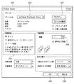
図2において、201はプリンタドライバのUI画面のウィンドウである。このプリンタドライバのウィンドウ201内の設定項目において、202は、印刷ジョブ(印刷データを含む)の出力先を選択する送信先選択カラムである。選択カラム202による選択により、操作者(ユーザ)は、画像形成システムにおいて、所望の出力先(画像形成装置)を選択することが可能である。
In FIG. 2,
203は印刷ジョブの中から印刷範囲を選択するページ設定カラムであり、ホストコンピュータ上で動作するアプリケーションソフトウエア(以下、「アプリケーション」という。)で作成された画像データのうち、どの範囲(どのページ)を出力するかを指定することができる。ユーザは、ページ設定カラム203を介して、画像形成装置に印刷出力させるべきページとして、全ページ印刷させることも、全ページ印刷させることなく特定のページを印刷させることも可能である。
204は画像形成装置に印刷出力させるべき出力部数を指定する部数設定カラムであり、図示の矢印(スクロールバーの矢印)をクリックすることで、部数の増減が設定できる。 Reference numeral 204 denotes a copy number setting column for designating the number of output copies to be printed out by the image forming apparatus, and the increase / decrease of the number of copies can be set by clicking an arrow (arrow of the scroll bar) shown in the figure.
207は送信先選択カラム202にて選択された画像形成装置に関する詳細設定を行なうためのプロパティキーである。ユーザによりキー207が入力されたことに応答し、プリンタドライバは、ホストコンピュータのディスプレイ上に図3及び図4に示す各詳細画面を表示させるように表示制御する。
図2の操作画面を介してユーザによる所望の設定が済んだ上で、OKキー205をキー入力すると、選択された画像形成装置は、ユーザの所望の設定に従って印刷処理を開始する。処理を取り消す場合には、キャンセルキー206をユーザが押下することで、プリンタドライバは印刷を取りやめの制御を行ない、ウィンドウ201の表示を終了させる。
When the user makes a desired setting via the operation screen of FIG. 2 and inputs an
図3及び図4は、プロパティキー207をユーザが選択したことに応答して表示される操作画面(UI)を例示する図である。
3 and 4 are diagrams illustrating an operation screen (UI) displayed in response to the user selecting the
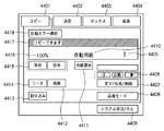
図3に示す画面には、例えば、「ページ設定310」、「仕上げ320」、「給紙330」、「印刷品質340」等のタブキーが設けられており、それらをクリック(図示しないホストコンピュータが具備するポインティングデバイス等の操作部で指示)することにより、「ページ設定310」に関する設定、「仕上げ320」に関する設定、「給紙330」に関する設定、「印刷品質340」に関する設定等の異なる各種詳細な印刷出力条件の設定を行なうことができる。
In the screen shown in FIG. 3, for example, tab keys such as “page setting 310”, “finishing 320”, “
図3は、「ページ設定310」が押下された場合の画面例を示している。図3において、301は、記録紙のサイズを選択する用紙サイズ設定部であり、302は、一枚の記録紙上に何ページの画像を配列形成させるか(N−up)、面つけレイアウトを設定する入力部である。303は、印刷時における記録紙の向きを設定する向き設定部であり、304は、印刷部数を設定する入力部である。
FIG. 3 shows an example of a screen when “page setting 310” is pressed. In FIG. 3,
また、図4は、図3に示す「仕上げ」タブ320が選択された場合の画面例を示している。この画面は、図2の操作画面によりユーザにより選択されたデバイスに関する固有の設定を行なう画面である。「仕上げ」タブ320がユーザによるキー操作により選択された場合、これを受けたプリンタドライバ505は、複数のフィニッシャプロファイルを保持している場合には、その複数のフィニッシャの一つを選択させるために、不図示のフィニッシャ選択画面を表示する。そして、フィニッシャが選択されると、プリンタドライバは、選択されたフィニッシャのプロファイル情報を読み込み、読み込んだプロファイル情報に応じて図4に示すような操作画面を表示部に表示させる。
FIG. 4 shows an example of a screen when the “Finish”
例えば、ステープル処理の設定、ソート処理の設定、パンチ処理の設定、穴あけ処理の設定、製本処理の設定等、フィニッシングの設定を含むシート処理の設定、片面印刷するか両面印刷を実行させるかの設定、プリンタによる色味などのパラメータを変更する画像処理関連のより細かい調整等、各種の詳細設定が可能である。 For example, stapling settings, sort processing settings, punch processing settings, punching processing settings, bookbinding processing settings, sheet processing settings including finishing settings, and settings for single-sided or double-sided printing. Various detailed settings such as fine adjustments related to image processing for changing parameters such as color by the printer are possible.
例えば、図2で選択した画像形成装置に対して、選択欄401から片面印刷(または、選択を切り替えて、両面印刷にすることも可能である)を選択し、選択欄402から、印刷物の後処理として製本綴じ方向を選択することができる。図4の選択欄402には、印刷綴じ方向として、長辺綴じ(左)が設定された状態を示している。尚、綴じ方向のバリエーションとしては、この他に、例えば、短辺綴じ(左)、短辺綴じ(右)、長辺綴じ(右)を選択することことが可能である。印刷物に対する後処理として、ニアラインフィニッシャ21で行なう後処理(例えば、くるみ製本)が指定されている場合は、2つの処理方式がある。第一処理方式は、プリンタドライバ505が、ニアラインフィニッシャ21に対する後処理内容とニアラインフィニッシャのIDが記述されたジョブ制御情報を、印刷ジョブ中に含めて画像形成装置10に送信するものであり、第二処理方式は、プリンタドライバ505が、ニアラインフィニッシャ21に対して後処理内容とジョブID(識別子)を記述したジョブチケットをプリンタドライバが生成し、ジョブチケットをニアラインフィニッシャへ出力するものである。
For example, for the image forming apparatus selected in FIG. 2, single-sided printing (or double-sided printing by switching the selection is possible) is selected from the
入力欄403をユーザが操作すると、プリンタドライバは、図4の操作画面における印刷詳細設定を初期値へ戻すように表示制御する。また、図示しないが、同様にして「印刷品質340」が選択されると、解像度やハーフトーンの設定を行なうことができる。
When the user operates the
404はOKキーで、ユーザによりこのキーが押下(指示)されると、プロパティ設定を有効にして、図2のUI画面に戻る。また、405はキャンセルキーで、このキーが押下(指示)されると、プロパティ設定を無効にして、図2のUIの画面に戻る。
プリンタドライバは、各種の詳細設定を含む印刷処理条件と、画像データとを印刷ジョブとして、指定されたデバイス(例えば、画像形成装置10、20)に出力することで、ホストコンピュータ側で設定した種々の印刷処理条件により、デバイスを制御して画像データの処理を実行させることが可能になる。
The printer driver outputs various print processing conditions including various detailed settings and image data as print jobs to specified devices (for example, the
(プリンタドライバ構成の説明)
図5は、ホストコンピュータ内部におけるプリンタドライバを含むソフトウェアの構成を例示する図である。図5においては、ホストコンピュータ1(図1)を例としているが、他のホストコンピュータ2においても同様の構成を有するものとする。502は、ホストコンピュータ1の全体的な制御を司るオペレーティングシステム(OS)であり、プリンタドライバ505やアプリケーションソフトウエア(プログラム)508は、このOS502上にインストールされ、OS502により制御される。アプリケーションプログラム508中のドライバUI組替アプリケーション512は、プロファイル保存領域5044に保存されたフィニッシャプロファイルの情報を基にプリンタドライバのUIを組み替えることが可能である。
(Description of printer driver configuration)
FIG. 5 is a diagram illustrating a configuration of software including a printer driver in the host computer. In FIG. 5, the host computer 1 (FIG. 1) is taken as an example, but the
ドライバUI組替アプリケーション512は、取得したフィニッシャプロファイルと現在のプリンタドライバのUIに表示されている機能の比較を行ない、UI上にフィニッシャの機能に関する表示を追加・削除する必要があるかを判定すること、そして、判定に応じて、UIの表示を更新する表示制御が可能である。この表示制御に関しては、例えば、図39Aのフローチャートにより詳細に説明する。尚、ドライバUI組替アプリケーション512は、プリンタドライバ505の一部として構成することも可能である。この場合、プリンタドライバ505がUI上にフィニッシャの機能に関する表示を追加・削除する必要があるかを判定することになる。ドライバUI組替アプリケーション512の機能は、OS502の一部の機能として提供されてもよい。この場合、OS502がUI上にフィニッシャの機能に関する表示を追加・削除する必要があるかを判定することになる。
The driver
プリンタドライバ505は、ユーザインターフェース(I/F)の表示や設定の保存などを行なうユーザI/Fドライバ506と、OS502を介してアプリケーションプログラム508から指示される印刷描画命令を、画像形成装置(10、20)が解釈可能なコードに変換するグラフィックドライバ507を有している。プリンタドライバ505はドライバUI組替アプリケーション512の処理に基づいて、プリンタドライバのUIを表示制御することができる。
The
ユーザI/Fドライバ506は、OS502を介してアプリケーションプログラム508から印刷設定が指示されたとき、上述の図2乃至図4に示す印刷設定ダイアログ及びプロパティシートを画面上に表示する。
When the user I /
なお、OS502が管轄する保存領域内に、プリンタドライバ505の設定保存領域503があり、ユーザI/Fドライバ506にてユーザが設定した印刷属性はこのプリンタドライバ設定保存領域503に保存される。また、ユーザI/Fドライバ506、グラフィックドライバ507、アプリケーションプログラム508はOS502を介して、このプリンタドライバ設定保存領域503にアクセスすることができ、ユーザが設定した印刷属性を読み取ることが可能である。
Note that there is a setting
更に、ホストコンピュータ側の通信I/F510と、画像形成装置側の通信I/F511と、が通信媒体(ネットワーク100)で接続されている。グラフィックドライバ507はOS502を介して、例えば、画像形成装置10に印刷ジョブ(印刷データ)の送信が可能であり、また、画像形成装置10の構成情報やステータスに関する情報を、OS502を介して取得することも可能である。
Further, a communication I /
(印刷の流れ)
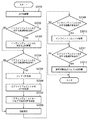
次に、ユーザがプリンタドライバ上で印刷属性の設定を行ない、印刷出力されるまでの流れを説明する。図6は、ユーザが印刷属性を設定する手順の流れを説明するフローチャートであり、図7はユーザが印刷指示を行ない印刷されるまでの流れを説明するフローチャートである。
(Printing flow)
Next, a flow until the user sets print attributes on the printer driver and prints out will be described. FIG. 6 is a flowchart for explaining a flow of a procedure for setting print attributes by the user, and FIG. 7 is a flowchart for explaining a flow until printing is performed after the user issues a print instruction.
まず、図6のステップS601においてユーザがアプリケーションプログラム508(以下、単に「アプリケーション」ともいう。)のメニューから印刷設定のメニューを選択する。この選択をきっかけとして、ステップS602において、アプリケーション508がOS502のAPI(Application Programming Interface)をコールして、プリンタドライバ505に印刷属性設定のプロパティシートを表示するように指示する。この指示により、OS502はプリンタドライバ505に印刷属性設定のプロパティシート表示の指示を行なう。
First, in step S601 of FIG. 6, the user selects a print setting menu from the menu of an application program 508 (hereinafter also simply referred to as “application”). In response to this selection, in step S602, the
ステップS603においてプリンタドライバ505のユーザI/Fドライバ506は、OS502からの指示を受けて、図2に示した印刷属性設定のプロパティシートを表示装置の画面上に表示する。続いて、ステップS604において、ユーザは前述した図2〜図4のプロパティシート上で所望の印刷属性設定を行なう。ユーザは、印刷属性設定を行った後、図2のプロパティシートのOKボタン205を押下して、設定した印刷属性を確定する。このOKボタン205の押下を受けて、ステップS605において、ユーザI/Fドライバ506は、OS502のAPIをコールして、ユーザが設定した印刷属性設定値をOS502内のプリンタドライバ設定保存領域503に保存する。これで印刷属性設定とその設定値の保存が完了する。
In step S603, in response to an instruction from the
次に、ユーザは、設定した印刷属性に従ってドキュメントを印刷するために、図7のフローチャートに従った手順を実行する。まず、ステップS701において、アプリケーション508のメニューから印刷メニューを選択する。この選択指示により処理をステップS702に進める。ステップS702において、アプリケーション508はOS502のAPIをコールしてプリンタドライバ505に印刷開始指示を行なう。なお、この過程で一度、図2に示す印刷設定ダイアログを表示するケースもある。この印刷指示を受けて、OS502はプリンタドライバ505に印刷開始指示を行なう。
Next, the user executes a procedure according to the flowchart of FIG. 7 in order to print the document according to the set print attributes. First, in step S701, a print menu is selected from the menu of the
ステップS703において、プリンタドライバ505を構成しているグラフィックドライバ507は、この印刷開始指示によりOS502のプリンタドライバ設定保存領域503から、保存されている印刷属性設定値を読み出し、画像形成装置に指示する印刷属性設定コードを生成し、指定された画像形成装置に送信する。続いて、ステップS704において、アプリケーション508はドキュメントデータに基づきOS502を介して印刷描画を行なう。
In step S703, the
ステップS705において、OS502は、グラフィックドライバ507に描画指示をして、グラフィックドライバ507は受信した印刷描画命令を画像形成装置が解釈可能な印刷コードに変換して画像形成装置に送信する。
In step S705, the
ステップS706において、画像形成装置は受信した、印刷属性設定コード、印刷コードに基づいて、レンダリング等の画像形成を行ない、印刷出力する。 In step S706, the image forming apparatus performs image formation such as rendering based on the received print attribute setting code and print code, and prints out the image.
以上述べた手順によりユーザが所望の印刷属性を設定し、印刷出力を得ることが可能となる。
(画像形成装置の構成)
図8は本発明の実施形態に係る画像形成装置の構成を示すブロック図である。同図に示すように、画像形成装置は、画像の読み取りを行なうスキャナ入力部801と、ファクシミリなどに代表される電話回線を利用した画像の送受信を行なうFAX部802を有する。また、ネットワークを利用して画像データや装置情報をやりとりするNIC(Network Interface Card)部803と、他の画像形成装置やホストコンピュータ等との間で情報の送受信を行なうことが可能な専用I/F部804、更に、USB(Universal Serial Bus)メモリに代表されるUSB機器と画像データの書き込みや読み出しを行なうためのUSBインターフェース(I/F部)805を備えている。
According to the procedure described above, the user can set a desired print attribute and obtain a print output.
(Configuration of image forming apparatus)
FIG. 8 is a block diagram showing the configuration of the image forming apparatus according to the embodiment of the present invention. As shown in the figure, the image forming apparatus includes a
ジョブ制御部800は、画像形成装置の用途に応じて画像データを一時的に保存し、その画像データ等を適宜読み出して、出力するための処理工程(処理経路)を制御することができる。また、ジョブ制御部800は、操作部813を介して操作者からの指示により、保存したハードディスク等のメモリから読み出した画像データを、専用I/F部804等を経由してホストコンピュータ1、2や他の画像形成装置等の外部装置にデータ転送を制御することができるものとする。
The
文書格納部807は、複数の画像データを格納することが可能なハードディスク等のメモリを具備している。例えば、スキャナ入力部801からの画像データ、FAX部802を介して入力されたファクシミリジョブの画像データ、NIC部803を介して入力されたコンピュータ等の外部装置からの画像データ、専用I/F部804を介して入力された他の画像形成装置からの画像データ等、複数種類の画像データを、ハードディスク等のメモリに格納することができる。そして、ジョブ制御部800は、プリンタ部810等の出力部における処理に従い、ハードディスク等のメモリに格納した画像データを適宜読み出して、プリンタ部810等の出力部に転送制御する。
The
画像データを文書格納部807に格納する際に、圧縮伸張部806は、必要に応じて、画像データを圧縮して格納したり、逆に圧縮して格納された画像データを読み出す際に元の画像データに伸張して戻したりする処理を行なう。また、画像データがネットワークを経由する際には、JPEG、JBIG、ZIPなど圧縮データを使用することも可能であり、画像データが画像形成装置に入力された後、圧縮伸張部806は圧縮データを解凍(伸張)することができる。
When storing the image data in the
共通DB部808は、フォント、カラープロファイル、ガンマテーブルなど共通に扱われる各種パラメータテーブルなどが格納されており、必要に応じて呼び出すことができる。また、新しいパラメータやテーブルを格納し、修正、更新することができる。例えば、画像形成装置に対して新たに追加登録するニアラインフィニッシャに関する登録データを格納することも可能である。
The
PDLデータが入力された場合、ジョブ制御部800は、PDL部812によるRIP(Raster Image Processor)処理や、必要に応じて画像処理部811で印刷出力のための画像処理を行なうよう制御する。更に、ジョブ制御部800は、その際に作られる画像データの中間データやプリントレディデータ(印刷出力のためのビットマップデータやそれを圧縮したデータ)を必要に応じて、文書格納部807に再度格納するように、制御することもできる。
When PDL data is input, the
そして、ジョブ制御部800は、上述のプリントレディデータをプリンタ部810に送り、プリンタ部810でプリントアウトされた記録媒体(記録紙)は後処理部809で、仕分け処理や、製本等の仕上げ処理が行われる。
Then, the
ジョブ制御部800は、画像形成装置の使い方に応じて、例えば、以下のようにパスの切り替えを行なうことができる。
For example, the
複写機能 :スキャナ入力部→画像処理部→プリンタ部
FAX受信機能 :FAX部→画像処理部→プリンタ部
ネットワークスキャン:スキャナ入力部→NIC部
ネットワークプリント:NIC部→PDL部→画像処理部→プリンタ部
外部装置へのスキャン:スキャナ入力部→専用I/F部
外部装置からのプリント:専用I/F部→画像処理部→プリンタ部
外部メモリへのスキャン:スキャナ入力部→USB I/F部
外部メモリからのプリント:USB I/F部→PDL部→画像処理部→プリンタ部
ボックススキャン機能:スキャナ入力部→画像処理部→文書格納部
ボックスプリント機能:文書格納部→プリンタ部
ボックス受信機能 :NIC部→PDL部→画像処理部→文書格納部
ボックス送信機能 :文書格納部→NIC部
プレビュー機能 :文書格納部→操作部
上記以外にも、E−mailサービスやWebサーバ機能を初めとして、様々な機能との組み合わせが考えられるが、ここでは割愛する。
Copy function: Scanner input unit-> Image processing unit-> Printer unit FAX reception function: FAX unit-> Image processing unit-> Printer unit Network scan: Scanner input unit-> NIC unit Network print: NIC unit-> PDL unit-> Image processing unit-> Printer unit Scan to external device: Scanner input unit → Dedicated I / F unit Print from external device: Dedicated I / F unit → Image processing unit → Printer unit Scan to external memory: Scanner input unit → USB I / F unit External memory Printing from: USB I / F part-> PDL part-> Image processing part-> Printer part Box scan function: Scanner input part-> Image processing part-> Document storage part Box print function: Document storage part-> Printer part Box reception function: NIC part → PDL part → Image processing part → Document storage part Box transmission function: Document storage part → NIC part Preview Features: document storage unit → In addition to the operating unit above, as the beginning of the E-mail service and Web server function, it is conceivable combination of the various functions, will be omitted here.
また、ボックススキャン、ボックスプリント、ボックス受信、あるいは、ボックス送信とは、文書格納部807を利用したデータの書き込みや、読み出しを伴う画像形成装置の処理機能であり、ジョブ毎やユーザ毎に文書格納部807内のメモリを分割して、一次的にデータを保存して、ユーザIDやパスワードを組み合わせてデータの入出力を行なう機能である。
Box scan, box print, box reception, or box transmission is a processing function of the image forming apparatus that involves writing and reading of data using the
更に、操作部813は、上記の様々なフローや機能を選択したり操作指示したりするためのものであるが、操作部813の表示装置の高解像度化に伴い、文書格納部807にある画像データをプレビューし、確認後OKならばプリントすることもできる。
Further, the
画像形成装置10は、インラインフィニッシャ11とニアラインフィニッシャ21、22に対して、その機能を使うように設定することができる。各フィニッシャの機能を記述したそれぞれのフィニッシャプロファイル(後述)は、画像形成装置内に保持されており、そのプロファイル情報を元に使用する機能の設定が行なわせるべく、ホストコンピュータ(例えば、図1の1または2)に送信される。設定操作は、フィニッシャプロファイルを読み出したホストコンピュータにより行われる。画像形成装置10によるフィニッシャプロファイルの取得は、画像形成装置の出荷時点で接続され得る全ての種類のフィニッシャのプロファイルを、その画像形成装置内に保存しておくという方法が考えられる。この場合には、出荷後に新たに当該画像形成装置によってサポートされるニアラインフィニッシャ21、22が現れた場合は、その新しいニアラインフィニッシャ21、22がネットワークに接続になった時点で、画像形成装置10がそのニアラインフィニッシャ21、22内にあるプロファイル情報(ニアラインフィニッシャプロファイル)を取得する。更には、フィニッシャ内にプロファイル情報がない場合か、設置後に機能変更や追加などでプロファイル情報がアップデートされた場合などには、フィニッシャメーカのホームページなどからプロファイル情報を取得することもできる。したがって、出荷時点ではフィニッシャのプロファイルを持たなくても、使用時にそれを取得することができる。なおプロファイル情報は対応する装置の能力特性を記述した情報であり、能力情報あるいは特性情報ということもできる。
(フィニッシャの設定)
ジョブ制御部800は、後処理部809(インラインフィニッシャ、ニアラインフィニッシャ、オフラインフィニッシャ)の機能を記述したフィニッシャプロファイルを、例えば、共通DB部808に保持し、そのフィニッシャプロファイルを元に使用する機能の設定を行なう。
The
(Finisher setting)
The
フィニッシャプロファイルは、画像形成装置の出荷時点で、画像形成装置に接続されると想定される全てのフィニッシャのプロファイルを、共通DB部808内に保存しておくことができる。
The finisher profile can store in the
あるいは、出荷後に新たに接続されることになったフィニッシャに関しては、画像形成装置のジョブ制御部800は、新しいフィニッシャがネットワークに接続になった時点で、そのフィニッシャ内にあるプロファイル情報を取得することができる。画像形成装置のジョブ制御部800は、NIC部803を介して、ネットワーク100に接続されているニアラインフィニッシャ(例えば、図1の場合、21、22)やフィニッシャシステム(例えば、図1の場合、200)と通信を行ない、それらフィニッシャの持つフィニッシャプロファイルのデータを取得することができるものとする。
Alternatively, for a finisher newly connected after shipment, the
更には、フィニッシャ内にプロファイル情報がない場合、設置後に機能変更や追加などでプロファイル情報がアップデートされた場合などの場合、画像形成装置のジョブ制御部800は、フィニッシャメーカのホームページなどからプロファイル情報をダウンロードして取得することも可能である。
Further, when there is no profile information in the finisher, or when the profile information is updated due to a function change or addition after installation, the
(フィニッシャとプロファイルの管理)
(ポストプレスの構成)
本実施形態では、インラインフィニッシャの一例として中綴じ製本機、ニアラインフィニッシャの例として、無線綴じ製本機(図10)、断裁機(図11)を例として説明する。
(Finisher and profile management)
(Composition of post press)
In the present embodiment, a saddle stitch bookbinding machine (FIG. 10) and a cutting machine (FIG. 11) will be described as examples of a saddle stitch bookbinding machine as an example of an inline finisher, and an example of a nearline finisher.
図9は、ニアラインフィニッシャにおけるコントローラ900の内部構成の一例を示す図である。900は後処理デバイス920を制御するコントローラであり、901はホストコンピュータや画像形成装置などの他のネットワーク機器と通信を行なうネットワーク部である。902は、一時的に情報を保管するDRAMのような一次記憶装置やHDDのような2次記憶装置である。903はニアラインフィニッシャにおけるジョブの制御を行なう制御部であり、904はユーザからのID入力などを受け付ける操作部である。905は入力されたジョブ情報を解釈して、後処理デバイスを制御できる形式に変換するジョブ制御情報解釈部であり、906は後処理デバイス920を制御するデバイス制御部である。これらのモジュールによりニアラインフィニッシャが構成されている。
FIG. 9 is a diagram illustrating an example of an internal configuration of the
図10において、コントローラ1001は、図9で説明したコントローラ900の内部構成に対応する機能を有しており、コントローラ1001の制御の下、ネットワーク100を介した通信と、無線綴じデバイス1002の制御が実行される。同様に、図11において、コントローラ1101は、図9で説明したコントローラ900の内部構成に対応する機能を有しており、コントローラ1101の制御の下、ネットワーク100を介した通信と、断裁デバイス1102の制御が実行されるものとする。
10, the
(ニアラインフィニッシャにおける処理の流れ)
図12は、ニアラインフィニッシャにおける処理の流れを説明するフローチャートである。まず、ステップS1201において、ネットワーク部901がジョブ制御情報を受信し、ジョブ制御情報解釈部905が受信したジョブ制御情報を解釈し(S1202)、後処理デバイス920を制御することが可能な内部形式のデータに変換して、記憶装置902に印刷ジョブIDと共に保管する(S1203)。次に、操作者が操作部904において、これから処理を行ないたい印刷ジョブのジョブIDを入力し(S1204)、この入力に基づいてジョブ制御部903が記憶装置902から該当する印刷ジョブに関するジョブ制御情報を取得し(S1205)、デバイス制御部906にジョブ制御情報を設定する。そして、デバイス制御部906は、ジョブ制御情報に従い後処理デバイス920を制御する(S1206)。
(Processing flow in the nearline finisher)
FIG. 12 is a flowchart for explaining the flow of processing in the nearline finisher. First, in step S1201, the network unit 901 receives job control information, the job control
図12のフローチャートでは、記憶装置902にジョブ制御情報を一旦格納し、適宜読み出しを行なって処理を進めているが、例えば、ネットワーク上にジョブ制御情報を格納するサーバ(MFPでもよい)を設け、受信したジョブ制御情報をサーバに登録するようにしてもよい。この場合、操作部904からジョブIDが入力された際、サーバへ接続し、入力されたジョブIDに対応するジョブ制御情報をサーバから取得して、ジョブ制御情報解釈部905にジョブ制御情報を受け渡すようにしてもよい。
In the flowchart of FIG. 12, the job control information is temporarily stored in the
(プロファイルの内部構造)
本実施形態では、フィニッシャプロファイルをXML(eXtensible Markup Language:拡張可能なマーク付き言語)形式で記述している。フィニッシャは、製本機、断裁機、折機など種類が多様であり、それぞれの機種ごとに機能が大きく異なる。また、新規機能の追加などにより同じ種類のフィニッシャにおいても機能の追加によりプロファイルは大きく異なるものとなる。そのため、機能の追加等に適切に対応できる表現形式としてタグ形式で記述したXML形式によりフィニッシャプロファイルを記述している。もちろん、新規機能追加等に対して適応的に記述できる形式であれば、XML形式に限定されるものではなく、どのようなものであっても問題はない。
(Internal structure of profile)
In the present embodiment, the finisher profile is described in an XML (extensible Markup Language) format. There are various types of finishers, such as bookbinding machines, cutting machines, and folding machines, and the functions differ greatly depending on the model. In addition, even when the same type of finisher is added due to the addition of a new function or the like, the profile is greatly different due to the addition of the function. Therefore, the finisher profile is described in the XML format described in the tag format as an expression format that can appropriately correspond to the addition of a function or the like. Of course, the format is not limited to the XML format as long as it can be described adaptively with respect to the addition of a new function or the like.
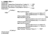
図13は、製本機のフィニッシャプロファイルを記述した例を示す図であり、図14は、断裁機のフィニッシャプロファイルを記述した例を示す図である。 FIG. 13 is a diagram illustrating an example describing a finisher profile of a bookbinding machine, and FIG. 14 is a diagram illustrating an example describing a finisher profile of a cutting machine.
図13、図14において、「FinishingType」(1301、1401)は製本機、断裁機などの種類を示し、「Manufacturer」(1302、1402)は製造したメーカ名を示す。「ProductName」(1303、1403)は型式を表している。図13では「ABC社が製造した11ABCという型式の製本機(Type : Bookbinding)」を表している。図14では「XYZ社が製造した10XYZという型式の断裁機(Type : Cutting)」を表している。図13の「Booklet」(1304)や図14の「Cutting」(1404)といったタグは製本機や断裁機の固有の能力を記述したものである。 13 and 14, “FinishingType” (1301, 1401) indicates the type of bookbinding machine, cutting machine, etc., and “Manufacturer” (1302, 1402) indicates the name of the manufacturer. “ProductName” (1303, 1403) represents a model. FIG. 13 shows “11ABC type bookbinding machine manufactured by ABC (Type: Bookbinding)”. FIG. 14 shows a “10XYZ type cutting machine (Type: Cutting) manufactured by XYZ company”. Tags such as “Booklet” (1304) in FIG. 13 and “Cutting” (1404) in FIG. 14 describe the unique capabilities of the bookbinding machine and the cutting machine.
例えば、製本機の場合(図13)、製本のバリエーションとして、「中とじ折」(1305)、「平とじ」(1306)、「コーナーとじ」(1307)、「二つ折」(1308)、「平とじ折」(1309)、「コーナーとじ折」(1310)が製本機能として登録されている。 For example, in the case of a bookbinding machine (FIG. 13), variations in bookbinding include “saddle folding” (1305), “flat binding” (1306), “corner binding” (1307), “double folding” (1308), “ “Folding and folding” (1309) and “Folding and folding” (1310) are registered as bookbinding functions.
また、断裁機の場合(図14)、例えば、裁断のサイズの情報(1405、1406)や、裁断することが可能な最大厚さに関する情報1407が登録されている。また図14の「cutting」タグ1404において、最大入力寸法(MaxInputDimensions)が縦横(X、Y)それぞれ360mmであることが記述されている。また、最大出力寸法(MaxOutputDimensions)が、縦横(X、Y)それぞれ310mmであること、最小出力寸法(MinOutputDimensions)が、横(X)が80mm、縦(Y)が150mmであることが記述されている。また、最大厚み(MaxThickness)が70mmであることが記述されている。
In the case of a cutting machine (FIG. 14), for example, information on cutting size (1405, 1406) and information 1407 on the maximum thickness that can be cut are registered. Further, in the “cutting”
このように、フィニッシャのプロファイル情報には、機能の種類(機種)、メーカ名、形式名、機能毎の性能(たとえば寸法やとじ位置など)が定義されている。このプロファイル情報は、たとえばフィニッシャの記憶装置2101に保存されており、画像形成装置に読み出されて収集されるか、ホストコンピュータとしての情報処理装置のプリンタドライバの制御により直接ニアラインフィニッシャから収集されてもよい。
Thus, in the finisher profile information, the function type (model), manufacturer name, model name, and performance for each function (for example, dimensions and binding position) are defined. This profile information is stored, for example, in the
各フィニッシャの固有の機能に関しては、それぞれ個別にタグで定義することでプロファイルの記述が可能になる。 With regard to the unique functions of each finisher, it is possible to describe a profile by individually defining the tags with tags.
(フィニッシャ接続とプロファイルの管理)
図15は、画像形成装置10において、フィニッシャプロファイルに関する処理部のブロック図である。画像形成装置10は、外部との通信を行なうための通信I/F1502、フィニッシャプロファイルの管理及び外部からの取得要求に対してプロファイルの送信を行なうフィニッシャプロファイル制御部1503、フィニッシャの名称や対応するフィニッシャプロファイル名、接続状況などを管理するフィニッシャ接続管理テーブル1504、フィニッシャプロファイルの具体的な内容を保存するフィニッシャプロファイル保存領域1505を有する。なお、画像形成装置10に接続可能なフィニッシャは予め登録されており、フィニッシャ名称などの情報はフィニッシャ接続管理テーブル1504に保存され、それぞれのフィニッシャに対応するプロファイルはフィニッシャプロファイル保存領域1505に保存されているものとする。
(Finisher connection and profile management)
FIG. 15 is a block diagram of a processing unit related to the finisher profile in the
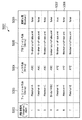
図16は、フィニッシャ接続管理テーブル1504の内容を例示する図であり、このテーブルには画像形成装置に接続可能なフィニッシャの情報が格納されている。フィニッシャ接続管理テーブル1504に登録されている項目は、管理番号1602 (変数型はUnsigned Short)、フィニッシャ名称1603 (変数型はString)、メーカ名称1604 (変数型はString)、対応するプロファイルのファイル名称1605 (変数型はString)、そしてフィニッシャの接続状態1606 (変数型はBooleanで、falseの場合は未接続、trueの場合は接続を示す)から構成されている。 FIG. 16 is a diagram illustrating the contents of the finisher connection management table 1504, and information on finishers connectable to the image forming apparatus is stored in this table. Items registered in the finisher connection management table 1504 are management number 1602 (variable type is Unsigned Short), finisher name 1603 (variable type is String), manufacturer name 1604 (variable type is String), and file name of the corresponding profile. 1605 (variable type is String), and finisher connection status 1606 (variable type is Boolean, false indicates unconnected, true indicates connection).
例えば、管理番号1602における#5の欄は、フィニッシャ名称1603が「Finisher-X」、メーカ名称1604が「XYZ」社、対応するプロファイルのプロファイル名称1605が「finisher-x-of-xyz.xml」であることを示している。同欄のフィニッシャの接続状態1606は、「true」であるため接続されていることを示している。また他の欄については同様に解釈することができるが、このフィニッシャ接続管理テーブル1504では管理番号#5のフィニッシャ以外は未接続状態(false)となっている。
For example, in the
次に、図17のフローチャートに従い、ニアラインフィニッシャを画像形成装置に接続する手順を説明する。ここで接続するフィニッシャは、例として、XYZ社の「Finisher-Y」(図15のフィニッシャ接続管理テーブル1504では管理番号#6に対応する)であるとする。ユーザは新しいニアラインフィニッシャを設置し、画像形成装置とニアラインフィニッシャをLANケーブル等の所定の通信媒体で接続しておく。図17は、画像形成装置10のフィニッシャプロファイル制御部1503により実行される。すなわち画像形成装置10のプロセッサ1507により実行される。
Next, a procedure for connecting the nearline finisher to the image forming apparatus will be described with reference to the flowchart of FIG. The finisher to be connected here is, for example, “Finisher-Y” of XYZ (corresponding to
ステップS1701において、操作者は新しいフィニッシャを設置し、画像形成装置(例えば、図1の10または20)とフィニッシャを通信媒体で接続する。次に、ステップS1702において、操作パネルを介してユーザは、ネットワーク上のニアラインフィニッシャに対して接続操作を行ない、ニアラインフィニッシャを利用可能にすべく指示を行なう。操作者は画像形成装置(10、20)の操作パネルからフィニッシャの接続状態1606として、未接続(false)を接続状態(true)に変える。この操作の内容は図21〜図23を参照して後に説明する。そして、ステップS1703において、フィニッシャプロファイル制御部1503は、ニアラインフィニッシャから応答があり、利用可能であると判断すると、フィニッシャ接続管理テーブル1504の接続状態を更新する。
In step S1701, the operator installs a new finisher, and connects the image forming apparatus (for example, 10 or 20 in FIG. 1) and the finisher through a communication medium. Next, in step S1702, the user performs a connection operation on the nearline finisher on the network via the operation panel, and gives an instruction to make the nearline finisher available. The operator changes the unconnected (false) to the connected state (true) as the
(接続状態の更新操作)
図21は、画像形成装置(10、20)における操作パネルの初期状態を示す図である。操作者はフィニッシャの接続設定を行なうために、まず図21のオプション(Options)ボタン2101を押下する。このオプション(Options)ボタンは画像形成装置のオプション設定を行なうためのボタンであり、このボタンを押下することにより図22の画面が表示される。操作者は更に「Finisher Registration」ボタン2202を押下する。このボタンを押下することにより、図23のフィニッシャ接続登録画面が表示される。この画面は登録可能なフィニッシャの一覧が表示されるとともに、各フィニッシャの接続登録を行なうことができる。フィニッシャの一覧は、フィニッシャ名称2301、メーカ名称2302、接続状態2303から構成される。この一覧表は一度に7個のフィニッシャが表示されているが、この7個の表示の前後にリスト化されるフィニッシャを閲覧する場合、ボタン(2304、2305)を押下することにより表示をスクロールすることができる。
(Connection status update operation)
FIG. 21 is a diagram illustrating an initial state of the operation panel in the image forming apparatus (10, 20). The operator first presses an
また、フィニッシャの接続登録あるいは接続登録の解除は、対象のフィニッシャ表示のいずれかをタッチすることにより選択状態(例えば、2307を参照)として、そのフィニッシャを接続登録する場合は、「Connect」ボタン2309、接続登録を解除する場合は、「De-Connect」ボタン2308に押下すればよい。
In addition, when a finisher connection is registered or canceled, the finisher connection is registered by touching one of the target finisher displays to select the finisher (see 2307 for example). In order to cancel the connection registration, the “De-Connect”
ここでは、XYZ社のFinisher-Yを接続登録するため、2307の行のいずれかにタッチしてFinisher-Yを選択状態として、「Connect」ボタン2309を押下すれば、このフィニッシャが接続登録される。「Connect」ボタン2309の押下に応じて、画像形成装置10からニアラインフィニッシャへ対して接続要求(利用可能要求)が発行され、その接続要求に対して応答が得られれば、利用可能であると判断し「Connected」と表示する。応答がなければ指定されたニアラインフィニッシャが利用可能な状態にないと判断して表示を変更しない。最後にこの設定を有効にして、画像形成装置本体の操作パネルの初期状態に戻るため、「OK」ボタン2311を押下する。この登録作業を破棄する場合は、「Cancel」ボタン2310にタッチすれば、この画面で操作した内容はすべて破棄され、画像形成装置におけるフィニッシャ接続管理テーブル1504の更新作業は行われない。
Here, in order to register connection of Finisher-Y of XYZ company, if one of the
図23のフィニッシャ接続登録画面において、操作者はXYZ社のFinisher-Y2307を接続登録したので、図26の2601に示すように#6のFinisher-Yの接続状態はfalse(図16の1607)からtrue(図26の2601)に変更される。
In the finisher connection registration screen of FIG. 23, since the operator has registered connection of Finisher-
以上の手順により、新たに追加するニアラインフィニッシャに関する接続登録処理が完了する。尚、上述の説明では、ニアラインフィニッシャの接続後に操作者が画像形成装置の操作パネルでフィニッシャの接続登録の設定を行ったが、フィニッシャ接続管理テーブル1504が更新できれば、この手順に限定されるものではない。例えば、画像形成装置(10、20)とフィニッシャとはネットワーク100で接続されているため、接続時のプロトコルを定義して、画像形成装置(10、20)とフィニッシャ同士がそのプロトコルに基づき通信することにより、画像形成装置(10、20)がフィニッシャを認識して、接続登録することも可能である。
With the above procedure, the connection registration process for the newly added nearline finisher is completed. In the above description, the operator sets finisher connection registration on the operation panel of the image forming apparatus after the nearline finisher is connected. However, the procedure is not limited to this procedure as long as the finisher connection management table 1504 can be updated. Absent. For example, since the image forming apparatus (10, 20) and the finisher are connected via the
画像形成装置はさらに、接続されたニアラインフィニッシャに対してフィニッシャプロファイルの取得要求を送信し、それに応じてニアラインフィニッシャが送信するフィニッシャプロファイルを受信する工程を実行する。受信したフィニッシャプロファイルはフィニッシャプロファイル保存領域1505に保存される。また、受信したフィニッシャプロファイルの名称は、フィニッシャ管理テーブル1504のフィニッシャプロファイル名1605に登録される。また、フィニッシャプロファイルに関連づけて、フィニッシャのアドレスが登録される。
The image forming apparatus further transmits a finisher profile acquisition request to the connected nearline finisher, and executes a process of receiving the finisher profile transmitted by the nearline finisher accordingly. The received finisher profile is stored in the finisher
なお、ニアラインフィニッシャのプロファイル情報は、このように画像形成装置が、登録されたニアラインフィニッシャから読み取って、その後コンピュータが取得しても良いが、コンピュータがニアラインフィニッシャから直接プロファイル情報を取得することも出来る。 Note that profile information of a near-line finisher, thus the image forming apparatus, reads from the near-line finisher has been registered, then the computer may acquire, but the computer to acquire directly profile information from the near-line finisher I can do it.
(フィニッシャプロファイルの取得)
次に、プリンタドライバが画像形成装置からフィニッシャプロファイルを取得し、保存する手順を説明する。
(Acquire finisher profile)
Next, a procedure for the printer driver to acquire and save a finisher profile from the image forming apparatus will be described.
図5の構成において、プロファイル保存領域504はプリンタドライバ505が画像形成装置(例えば、図1の10)から取得したフィニッシャプロファイルを保存するOS502内の記憶領域である。プリンタドライバ505は、OS502のAPI(Application Programming Interface)を通してプロファイル取得モジュールを起動し、このプロファイル取得モジュールを用いて、画像形成装置10から取得したフィニッシャプロファイルを、プロファイル保存領域504に保存する。プロファイル取得モジュールは、プリンタドライバ505の一部のモジュールとして構成してもよし、OS502の一部の機能として提供されてもよい。また、フィニッシャプロファイルの要求や送信を行なうために、ホストコンピュータ側の通信I/F510と画像形成装置10側の通信I/F511間には、通信媒体(ネットワーク100)で接続されている。尚、通信に用いるプロトコルは、プリンタドライバからのフィニッシャプロファイル取得の要求、及び画像形成装置からフィニッシャプロファイルの具体的な内容の送信が行なえればよく、本発明の趣旨は、プロトコルの指定により限定されるものではない。
In the configuration of FIG. 5, a
図24は、プリンタドライバ505が画像形成装置10からフィニッシャプロファイルを取得する処理の流れを説明するフローチャートである。
FIG. 24 is a flowchart for explaining the flow of processing in which the
ステップS2401において、プリンタドライバ505は画像形成装置10に接続登録されているフィニッシャプロファイルの取得を要求する。このプリンタドライバ505からの取得要求に応じて、ステップS2402において、画像形成装置10のフィニッシャプロファイル制御部1503は、フィニッシャ接続管理テーブル1504の登録内容を順に検索し、各フィニッシャの接続状態を確認する。例えば、図26に示すように、画像形成装置10が保持するフィニッシャ接続管理テーブル1504で、一番上の行の「Finisher-A」の接続状態をフィニッシャプロファイル制御部1503が確認すると、「Finisher-A」の接続状態は「false」となっている。
In step S <b> 2401, the
ステップS2403における接続状態の判定では、「Finisher-A」は接続状態が未接続「false」であるため(S2403−NO)、この場合、ステップS2405に処理を進める。ステップS2405では、フィニッシャ接続管理テーブル1504のすべてのフィニッシャについて確認が完了したか判定する。 In the determination of the connection state in step S2403, “Finisher-A” has the connection state of “false” (S2403—NO). In this case, the process proceeds to step S2405. In step S2405, it is determined whether confirmation has been completed for all finishers in the finisher connection management table 1504.
確認が全てのフィニッシャに対して完了している場合は(S2405−YES)、処理を終了し、確認が全て完了していない場合は(S2405−NO)、処理をステップS2402に戻し、フィニッシャ接続管理テーブル1504に登録されている次の「Finisher-B」、「Finisher-C」、「Binder-ABC」等について同様の処理を繰り返す。 If the confirmation has been completed for all finishers (S2405—YES), the process ends. If all the confirmations have not been completed (S2405—NO), the process returns to step S2402, and finisher connection management is performed. Similar processing is repeated for the next “Finisher-B”, “Finisher-C”, “Binder-ABC”, etc. registered in the table 1504.
例えば、フィニッシャ接続管理テーブル1504の#5に登録されている「Finisher-X」の場合、ステップS2403の判定は接続状態がtrueとなるので(S2403−true)、処理をステップS2404に進める。 For example, in the case of “Finisher-X” registered in # 5 of the finisher connection management table 1504, the determination in step S2403 is true in the connection state (S2403-true), and the process proceeds to step S2404.
ステップS2404において、フィニッシャプロファイル制御部1503は、接続状態(利用可能状態)にあるFinisher-Xに対応するフィニッシャプロファイルをプリンタドライバ505に送信する。この場合、フィニッシャプロファイル制御部1503は、フィニッシャ接続管理テーブル1504から、フィニッシャFinisher-Xに対応するフィニッシャプロファイル名称が「finisher-x-of-xyz.xml」(フィニッシャ名称Finisher-Xに対応する1605の欄を参照)であることを認識し、フィニッシャプロファイル保存領域1505からこのフィニッシャプロファイルを読み出し、プリンタドライバに送信する。
In step S2404, the finisher
フィニッシャ管理テーブルの最後のフィニッシャの確認が終わると、ステップS2405においてすべての確認が終了したことを示す情報をプリンタドライバに送信してこの流れ図の処理は終了する。 When the confirmation of the last finisher in the finisher management table is completed, information indicating that all the confirmations are completed is transmitted to the printer driver in step S2405, and the processing of this flowchart is completed.
一方、プリンタドライバ505は、画像形成装置から応答を受信し、その内容が、「終了」でないか判定する。「終了」でなければ、受信したデータはフィニッシャプロファイルであるから、それを保存領域に保存する。このようにして、プリンタドライバは、画像形成装置から接続状態(すなわち利用可能な状態)にあるニアラインフィニッシャのフィニッシャプロファイルを取得する。
On the other hand, the
(ホストコンピュータにおける印刷処理フロー)
ユーザは、ドキュメントを印刷するために、アプリケーションソフトウエアのメニューから印刷メニューを選択する。この選択指示に応じて、アプリケーションソフトウエアはOSのAPIをコールしてプリンタドライバに印刷開始指示を行なう。この印刷指示を受けて、OSはプリンタドライバに印刷開始指示を行なう。プリンタドライバを構成しているグラフィックドライバは、この印刷開始指示によりOSのプリンタドライバ設定保存領域から保存されている印刷設定情報を読み出し、画像形成装置に対するジョブ制御情報と、選択されたフィニッシャに対するフィニッシング設定を指示するジョブ制御情報とを生成する。
(Print processing flow in the host computer)
The user selects a print menu from the application software menu to print the document. In response to this selection instruction, the application software calls an OS API to instruct the printer driver to start printing. Upon receiving this print instruction, the OS instructs the printer driver to start printing. The graphic driver constituting the printer driver reads the print setting information stored in the printer driver setting storage area of the OS in response to this print start instruction, and sets job control information for the image forming apparatus and finishing setting for the selected finisher. Is generated.
そして、プリンタドライバは、生成されたジョブ制御情報を含む印刷ジョブを生成して画像形成装置に送信する(第一処理方式)か、または、印刷ジョブとジョブ制御情報のジョブチケットをそれぞれ画像形成装置および選択されたフィニッシャに送信する(第二処理方式)。 Then, the printer driver generates a print job including the generated job control information and transmits it to the image forming apparatus (first processing method), or print job and job control information job tickets respectively. And to the selected finisher (second processing method).
ジョブ制御情報には、具体的にJDF(Job Definition Format)(印刷物制作・製造の全工程を包括的に定義・記述し、管理・制御するXMLベースのファイル形式)の略称:本実施例では、簡単にジョブチケットと呼ぶ)、PJL(Print Job Language:印刷ジョブ言語:PDLを印刷ジョブとして扱うための一般的な言語)、PDL(Page Description Language:ページ記述言語)コマンドなどがある。本例ではJDFを用いている。選択されたフィニッシャがニアラインフィニッシャであれば、そのニアラインフィニッシャに対してジョブ制御情報としてジョブチケットが送信される。選択されたフィニッシャがインラインフィニッシャであれば、そのインラインフィニッシャが接続された画像形成装置に対して印刷ジョブ中のPJLまたはPDL内に記述されたジョブ制御情報が送信される。選択されたフィニッシャがオフラインフィニッシャであれば、ジョブ制御情報の内容は人間により可読かつ当該オフラインフィニッシャに入力可能な形式に変換されて印刷ジョブが生成され、画像形成装置に送信される。送信先がニアラインフィニッシャの場合、送信先アドレスは、フィニッシャプロファイルと関連づけて保存されているIPアドレスである。 In the job control information, specifically, an abbreviation of JDF (Job Definition Format) (an XML-based file format that comprehensively defines, describes, manages, and controls all processes of print production and manufacturing): For example, a job ticket), a PJL (Print Job Language), a PDL (Page Description Language) command, and the like. In this example, JDF is used. If the selected finisher is a nearline finisher, a job ticket is transmitted as job control information to the nearline finisher. If the selected finisher is an inline finisher, job control information described in the PJL or PDL in the print job is transmitted to the image forming apparatus to which the inline finisher is connected. If the selected finisher is an offline finisher, the contents of the job control information are converted into a format that can be read by a human and input to the offline finisher, and a print job is generated and transmitted to the image forming apparatus. When the transmission destination is a nearline finisher, the transmission destination address is an IP address stored in association with the finisher profile.
アプリケーションプログラムはドキュメントデータに基づきOSを介して印刷描画を行なう。OSに対して指示された印刷描画命令は、グラフィックドライバに対して印刷描画命令として渡される。グラフィックドライバは、受信した印刷描画命令を画像形成装置が解釈可能な描画情報に変換し、印刷ジョブを構成するデータ(単に印刷ジョブとも呼ぶ。)として画像形成装置に送信する。 The application program performs printing and drawing via the OS based on the document data. The print drawing command instructed to the OS is passed as a print drawing command to the graphic driver. The graphic driver converts the received print drawing command into drawing information interpretable by the image forming apparatus, and transmits the drawing information to the image forming apparatus as data constituting the print job (also simply referred to as a print job).
描画情報を受信した画像形成装置は、受信した描画情報に基づきレンダリングを行ない、印刷を行なう。描画情報を表すページ記述言語には、具体的にLIPS、PCL、PSなどがある。以上述べた手順によりユーザは所望の印刷出力を得ることが可能となる。 The image forming apparatus that has received the drawing information performs rendering based on the received drawing information and performs printing. Specific examples of page description languages representing drawing information include LIPS, PCL, and PS. The procedure described above enables the user to obtain a desired print output.
ホストコンピュータにおける印刷ジョブの後処理の設定に関する処理の流れを図25のフローチャートを参照して説明する。 A flow of processing relating to setting of post-processing of a print job in the host computer will be described with reference to a flowchart of FIG.
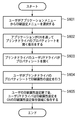
まず、ステップS2501において、操作者はアプリケーションプログラムを用いて印刷するデータを作成した後、プリンタドライバ505を起動する。
First, in step S2501, the operator creates data to be printed using an application program, and then activates the
ステップS2502において、プリンタドライバ505はフィニッシャの設定を行なうためのUI画面(図2)を表示させる。操作者によりプロパティボタン207が押下されると、プリンタドライバ505はプロパティ設定の詳細設定画面(図3)を表示させる。
In step S2502, the
ステップS2504において、印刷データに対してフィニッシング処理を行なう場合は、操作者による仕上げタブ(320)の選択により、プリンタドライバ505はフィニッシングに関する詳細設定画面(図4)を表示させる。この詳細設定画面(図4)において、必要な仕上げ項目(仕上げ機能)が選択されると、プリンタドライバ505は、プリンタドライバ505がサポートするフィニッシャが提供するフィニッシング機能の設定を行なう(S2505)。フィニッシング処理に必要な全てのフィニッシャ機能の設定が終了するまで、ステップS2504の処理が繰り返され(S2505−NO)、フィニッシャ機能の設定が完了すると(S2505−YES)、処理をステップS2506に進める。フィニッシャ機能の設定において、プリンタドライバ505は、新たに組み込んだフィニッシャ機能と、操作者の指定した仕上げ項目(仕上げ機能)とに矛盾が発生するか否か判定する。例えば、プリンタドライバの初期設定画面を利用して、新たに組み込んだフィニッシャ機能の設定をしようとする場合、実際にはフィニッシャで使用できない数値範囲の設定値が入力可能なままであったりする。このような矛盾が生じないようにフィニッシャに対する設定を矛盾なく入力可能にするために、プリンタドライバ505はUI画面を表示制御する。この内容は、後に詳細に説明する。
In step S2504, when the finishing process is performed on the print data, the
そして、ステップS2506において、操作者により図2のOKボタン205が押下されると、プリンタドライバ505は設定された内容に基づいて印刷指示を実行し、ホストコンピュータ(1、2)から画像形成装置(10,20)に対して、生成されたジョブ制御情報を含む印刷ジョブが出力される(S2507)。
In step S2506, when the
(フィニッシング処理)
次に、プリンタドライバが第一処理方式を採用して、ニアラインフィニッシャに対する後処理内容を記述したジョブ制御情報を印刷ジョブに含めて画像形成装置に送信し、画像形成装置がジョブ制御情報を受け取り、ジョブ制御情報内のフィニッシング処理に関する記述に応じて実行する処理フローを図58の参照により説明する。
(Finishing process)
Next, the printer driver adopts the first processing method, includes job control information describing the post-processing content for the nearline finisher in the print job and transmits it to the image forming apparatus, and the image forming apparatus receives the job control information, A processing flow executed according to the description related to the finishing process in the job control information will be described with reference to FIG.
まず、ステップS5801にて、ジョブ制御情報をプリンタドライバなどから受信する。次に、ステップS5802において解析を行ない、ステップS5803にて画像形成装置内にて管理を行っているプロファイル情報から受信したジョブ制御情報が処理可能なフィニッシャが登録されているかどうかを判定する。このためには、例えば、プロファイル情報に記述されたタグと、ジョブ制御情報に記述されるタグとの対応を記述した、画像形成装置の制御部が参照可能な対応表を用意することが好ましい。そして、ジョブ制御情報に記述されたタグに対応するタグにより、画像形成装置が収集したフィニッシャプロファイルを走査する。すべての機能タグについてヒットすれば、当該ジョブ制御情報は処理可能(すなわち指定されたフィニッシング処理を実行可能)である。ただし、本実施形態では、プリンタドライバによりフィニッシャプロファイルに応じたジョブ制御情報が生成されているため、ステップS5809はスキップされても良い。 First, in step S5801, job control information is received from a printer driver or the like. In step S5802, analysis is performed. In step S5803, it is determined whether a finisher that can process job control information received from profile information managed in the image forming apparatus is registered. For this purpose, for example, it is preferable to prepare a correspondence table in which correspondence between tags described in the profile information and tags described in the job control information can be referred to by the control unit of the image forming apparatus. Then, the finisher profile collected by the image forming apparatus is scanned with a tag corresponding to the tag described in the job control information. If all the function tags are hit, the job control information can be processed (that is, the designated finishing process can be executed). However, in the present embodiment, since the job control information corresponding to the finisher profile is generated by the printer driver, step S5809 may be skipped.
さて、ジョブ制御情報に記述された、機能を示すタグで記述された処理を処理可能なプロセスがなければ処理は終了する。ひとつでもある場合は、ステップS5804において登録されているフィニッシャがどのタイプのフィニッシャかを判断し、インラインフィニッシャの場合はステップS5805に進み、ステップS5806において、ジョブ制御情報で指定された設定にしたがってインラインフィニッシャに対するジョブ制御を行なう。 If there is no process that can process the process described by the tag indicating the function described in the job control information, the process ends. If there is one, it is determined which type of finisher is registered in step S5804. If it is an inline finisher, the process proceeds to step S5805. In step S5806, the inline finisher is set according to the setting specified in the job control information. Perform job control for.
ステップS5804の判定は、たとえば、ステップS5803で走査してヒットしたプロファイル情報に関連づけられたIPアドレスに基づいて識別可能である。IPアドレスが関連づけられていればニアラインフィニッシャである。オフラインフィニッシャについてはプロファイル情報がないので、ジョブIDなどにより判別できる。たとえばオフラインフィニッシャ向けのジョブ制御情報のジョブIDには、それが判別できるコードを付するなどしておけばよい。この場合ステップS5803においては、オフラインフィニッシャ向けのジョブ制御情報は判定の対象とはされない。 The determination in step S5804 can be identified based on, for example, the IP address associated with the profile information that was scanned and hit in step S5803. If an IP address is associated, it is a nearline finisher. Since there is no profile information for the offline finisher, it can be determined by the job ID or the like. For example, the job ID of the job control information for the offline finisher may be given a code that can identify it. In this case, in step S5803, the job control information for the offline finisher is not determined.
さて、ニアラインフィニッシャに対するプロセスであった場合は、ステップS5808において画像形成装置は、該当ニアラインフィニッシャへジョブ制御情報及びジョブIDを送信する。送信先は、ニアラインフィニッシャ接続時に入力されているIPアドレスとなる。オフラインフィニッシャであった場合は、ステップS5810にてジョブID、指定フィニッシャ名称の印字準備指示を行なう。 If the process is for the nearline finisher, the image forming apparatus transmits job control information and a job ID to the corresponding nearline finisher in step S5808. The transmission destination is the IP address that is input when the nearline finisher is connected. If it is an offline finisher, a print preparation instruction for the job ID and the designated finisher name is issued in step S5810.
なお、本実施形態においてプリンタドライバが第二処理方式を採用した場合は、プリンタドライバが宛先のフィニッシャに対して直接ジョブ制御情報を送信するために、プリンタではニアラインフィニッシャに対するジョブ制御情報しか受信されない。そのため、ステップS5802の後は、ただちにステップS5806を実行するように構成されていても良い。またプリンタにおいては、ジョブ制御情報の他、印刷ジョブを受信してそれを実行することで印刷処理を行なうことはもちろんである。 In the present embodiment, when the printer driver adopts the second processing method, the printer driver transmits job control information directly to the destination finisher, so that the printer receives only job control information for the nearline finisher. Therefore, step S5802 may be configured to execute step S5806 immediately after step S5802. In addition to the job control information, the printer receives the print job and executes it to execute the printing process.
次にステップS5811にてすべてのプロセス(後処理)を確認したかどうか判断しまだ処理すべきプロセスが残っている場合はステップS5804に戻り次のプロセスに関して処理を続ける。もしステップS5811においてすべてのプロセスの処理が終了したと判断した場合は終了する。 Next, in step S5811, it is determined whether all processes (post-processing) have been confirmed. If there are still processes to be processed, the process returns to step S5804 to continue the process for the next process. If it is determined in step S5811 that all processes have been completed, the process ends.
以上により、プリンタのインラインフィニッシャにより後処理が実行される。そして、もしもプリンタに対してニアラインフィニッシャのジョブ制御情報が送信されてきた場合であっても、宛先のニアラインフィニッシャにジョブ制御情報を転送できる。 As described above, post-processing is executed by the inline finisher of the printer. Even if the nearline finisher job control information is transmitted to the printer, the job control information can be transferred to the destination nearline finisher.
(ニアラインフィニッシャの設定)
図18は、画像形成装置に対応するニアラインフィニッシャを登録する処理の流れを説明するフローチャートである。操作者は、画像形成装置(例えば、図1の10、20)の操作部813を介して、本処理の操作を行なうことができる。まず、ステップ1801において、操作者は、ニアラインフィニッシャのIPアドレスを入力する。このIPアドレスの指定は、直接ニアラインフィニッシャに対するIPアドレスを入力してもよいし、所定のサブネットのIPアドレスを入力してもよい。
(Nearline finisher setting)
FIG. 18 is a flowchart for explaining the flow of processing for registering a nearline finisher corresponding to the image forming apparatus. The operator can perform this process via the
次に、ステップ1802において、入力されたIPアドレスに基づいて、あらかじめ画像形成装置のフィニッシャプロファイル保存領域903に記憶されているフィニッシャリストから該当するフィニッシャを特定し、特定された画像処理装置が接続可能なフィニッシャのリストを表示する。これにより操作者は、表示されたリストからニアラインフィニッシャのメーカや型番の一覧から該当するものを選択することにより対応プロファイルを指定する。そして、ステップS1803において、先のステップS1801及びS1802で入力した内容が正しい内容かを操作者が確認したうえで、ステップS1804において、ニアラインフィニッシャを登録する。登録の内容は、例えば、共通DB部808に格納しておくことが可能である。
Next, in step 1802, based on the input IP address, the corresponding finisher is specified from the finisher list stored in the finisher
また別の実施形態としてニアラインフィニッシャからメーカや型番がわかるIDを取得できる場合は、ユーザがIPアドレスを入力した段階で該当IPアドレスに対してIDの取得要求を発行してニアラインフィニッシャからそのIDを取得して表示し、ユーザによりIDが選択されたことに応じて、そのIDに対応するフィニッシャに対してプロファイル情報の要求を行ない、該フィニッシャからネットワークに接続されて利用可能なフィニッシャとしてプロファイル情報を取得してフィニッシャ管理テーブルを書き替えることも可能である。フィニッシャプロファイルは、入力されたIPアドレスのフィニッシャに対して要求し、取得する。IPアドレスとプロファイル情報とは関連づけて保存ことも可能である。 In another embodiment, when an ID that identifies the manufacturer and model number can be acquired from the nearline finisher, an ID acquisition request is issued to the corresponding IP address when the user inputs the IP address, and the ID is acquired from the nearline finisher. When the user selects the ID, the profile information is requested to the finisher corresponding to the ID, and the finisher is connected to the network from the finisher and the profile information is used as a usable finisher. It is also possible to acquire and rewrite the finisher management table. The finisher profile is requested and acquired from the finisher of the input IP address. The IP address and profile information can be stored in association with each other.
(ホストコンピュータからのプロファイルの取得要求処理)
次に、ホストコンピュータ(1、2)から画像形成装置(10、20)に登録されたニアラインフィニッシャの一覧と、プロファイルの取得要求がなされた場合の処理を図19のフローチャートを参照して説明する。
(Process to acquire profile from host computer)
Next, a list of nearline finishers registered in the image forming apparatus (10, 20) from the host computer (1, 2) and processing when a profile acquisition request is made will be described with reference to the flowchart of FIG. .
まず、ステップS1901において、画像形成装置(10、20)がホストコンピュータ(1、2)から、フィニッシャプロファイルの取得要求を受信すると、処理をステップS1902に進め、図12、図18の処理で登録されたニアラインフィニッシャに対応するプロファイルを要求元のホストコンピュータ(例えば、図1の1または2)へ送信する。 First, in step S1901, when the image forming apparatus (10, 20) receives a finisher profile acquisition request from the host computer (1, 2), the process proceeds to step S1902, and is registered in the processes of FIGS. The profile corresponding to the nearline finisher is transmitted to the requesting host computer (for example, 1 or 2 in FIG. 1).
図19の処理では、操作者が登録したニアラインフィニッシャのプロファイルをホストコンピュータに送信しているが、ホストコンピュータからのプロファイル取得要求に対して、画像形成装置が保持しているニアラインフィニッシャ及びインラインフィニッシャ、更には、フィニッシャシステムのプロファイルを送信することも可能である。 In the process of FIG. 19, the profile of the nearline finisher registered by the operator is transmitted to the host computer. In response to the profile acquisition request from the host computer, the nearline finisher and inline finisher held by the image forming apparatus, Furthermore, it is also possible to transmit a finisher system profile.
(印刷処理の流れの説明)
次に、ホストコンピュータから送信されるジョブチケットであるJDF(Job Definition Format)を含む印刷ジョブを受信した画像形成装置(10、20)における印刷処理の流れを図20のフローチャートを参照して説明する。なお、JDFとは、入稿された印刷オーダーに関する各種の処理情報が記述されたデータファイルであるジョブチケットの一種である。もちろん、ジョブチケットの種類はJDFに限らない。
(Description of print processing flow)
Next, the flow of print processing in the image forming apparatus (10, 20) that has received a print job including a JDF (Job Definition Format) that is a job ticket transmitted from the host computer will be described with reference to the flowchart of FIG. . JDF is a type of job ticket that is a data file in which various processing information related to a submitted print order is described. Of course, the type of job ticket is not limited to JDF.
ステップS2001において、画像形成装置(10、20)が印刷ジョブを受信すると、ジョブ制御部800は、印刷ジョブに含まれるJDFを解釈する。そして、その中にインラインフィニッシャに対する処理があるか判定する(S2002)。インラインフィニッシャに対する処理が含まれていない場合は(S2002−No)、処理をステップS2004に進める。一方、ステップS2002の判定で、インラインフィニッシャに対する処理が含まれている場合は(S2002−YES)、処理をステップS2003に進める。
In step S2001, when the image forming apparatus (10, 20) receives a print job, the
ステップS2003において、ジョブ制御部800は、インラインフィニッシャに対するJDFを解釈する。
In step S2003, the
次に、ステップS2004において、ジョブ制御部800はJDFを解釈してニアラインフィニッシャに対する処理があるか判定する。ニアラインフィニッシャに対する処理がない場合(S2004−NO)、処理をステップS2008に進める。一方、ステップS2004の判定で、ニアラインフィニッシャに対する処理がある場合(S2004−YES)、処理をステップS2005に進め、ジョブ制御部800は、ジョブIDを生成する。そして、ステップS2006において、ジョブ制御部800は、ニアラインフィニッシャへ送信するべきJDFを生成し、ステップS2007において、ジョブ制御部800は、ニアラインフィニッシャに対して、ジョブIDとJDFを送信する。
In step S2004, the
ステップS2008において、ジョブ制御部800はプリンタ部810等を制御して印刷を実行する。
In step S2008, the
ステップS2009において、インラインフィニッシャに対する処理がある場合は(S2009−YES)、処理をステップS2010に進め、印刷実行(S2008)の結果として得られた印刷部の後処理としてインラインフィニッシャの処理を実行する。一方、インラインフィニッシャの処理がない場合は、ステップS2010の処理を行なわずに処理をステップS2011に進める。ステップS2011において、ニアラインフィニッシャに対する処理がない場合は(S2011−NO)、処理を終了し、ニアラインフィニッシャに対する処理がある場合は(S2011−YES)、処理をステップS2012に進める。ステップS2012では、該当するニアラインフィニッシャにおける処理と操作者に指示するために、ジョブID及び処理手順を記載した作業指示書を生成し、出力して、処理を終了する。 If there is a process for the inline finisher in step S2009 (S2009-YES), the process proceeds to step S2010, and the inline finisher process is executed as a post-process of the printing unit obtained as a result of the print execution (S2008). On the other hand, if there is no inline finisher process, the process proceeds to step S2011 without performing the process of step S2010. In step S2011, if there is no processing for the nearline finisher (S2011-NO), the processing is terminated. If there is processing for the nearline finisher (S2011-YES), the processing proceeds to step S2012. In step S2012, in order to instruct the operator and the processing in the corresponding nearline finisher, a work instruction document describing the job ID and processing procedure is generated and output, and the processing is terminated.
(フィニッシャ側の処理)
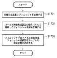
フィニッシャ側の処理の流れを図27のフローチャートを参照して説明する。まず、ステップS2701において、ニアラインフィニッシャは、操作者からIDが入力されるのを待機し、IDが入力された場合(S2702−YES)、処理をステップS2703に進める。
(Finisher side processing)
The flow of processing on the finisher side will be described with reference to the flowchart of FIG. First, in step S2701, the nearline finisher waits for an ID to be input from the operator, and if an ID is input (YES in S2702), the process proceeds to step S2703.
ステップS2703では、ニアラインフィニッシャ(例えば、図1の21、22)は、画像形成装置のジョブ制御部800に対してIDに対応したJDFを要求し、この要求に応じて送信されるJDFを取得する。
In step S2703, the nearline finisher (for example, 21 and 22 in FIG. 1) requests the JDF corresponding to the ID from the
ステップS2004において、JDFの内容を基に、記録紙のサイズ等、所定の後処理を行なうためのパラメータをフィニッシャが自動設定する。 In step S2004, the finisher automatically sets parameters for performing predetermined post-processing such as the size of the recording paper based on the contents of the JDF.
そして、ステップステップS2705において、設定したパラメータの内容をユーザに確認させる。 In step S2705, the user is caused to confirm the contents of the set parameters.
ステップS2706の判定で、現状の設定に問題がある場合(S2706−NO)、処理をステップS2708に進め、ニアラインフィニッシャに対するパラメータの設定を手動で設定するように要求する。 If it is determined in step S2706 that there is a problem with the current setting (NO in step S2706), the process advances to step S2708 to request that the parameter setting for the nearline finisher be set manually.
ステップS2706の判定で、自動設定されたパラメータに問題がない場合(S2706−YES)、または、ステップS2708において、手動でパラメータが修正された場合、処理をステップS2707に進め、フィニッシング処理を実行する。 If it is determined in step S2706 that there is no problem with the automatically set parameters (YES in step S2706), or if the parameters are manually corrected in step S2708, the process proceeds to step S2707 to execute the finishing process.
ニアラインフィニッシャの使用が複数台指定されている場合は、次工程のニアラインフィニッシャにおいても同様の処理を行なう。 When a plurality of near-line finishers are specified, the same process is performed in the next-line near-line finisher.
(ニアラインフィニッシャの追加に関する処理)
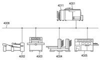
次に、画像形成システムに別のニアラインフィニッシャを新たに追加した場合の処理を説明する。図28は画像形成システムの構成を例示する図であり、1は、画像形成装置を制御するプリンタドライバがインストールされているホストコンピュータであり、10は画像形成装置本体、2803は給紙装置、11はインラインフィニッシャである。インラインフィニッシャ11は、例えば、ステープル機能やパンチ機能のほか、中綴じ製本機能を有する。
(Processing for adding a nearline finisher)
Next, processing when another nearline finisher is newly added to the image forming system will be described. FIG. 28 is a diagram illustrating the configuration of an image forming system. 1 is a host computer in which a printer driver for controlling the image forming apparatus is installed, 10 is an image forming apparatus main body, 2803 is a sheet feeding apparatus, Is an inline finisher. The
2806はニアラインフィニッシャである無線綴じ製本機である。また、ホストコンピュータ1、画像形成装置10、ニアラインフィニッシャ2806は、ネットワーク100に接続されているものとする。
(無線綴じ製本機の接続と特性情報ファイル)
操作者は、図15〜図17で説明したニアラインフィニッシャを接続する手順により、ニアラインフィニッシャである無線綴じ製本機2806を画像形成システムに接続することができる。接続手順を終えると図15におけるフィニッシャプロファイル保存領域1505に無線綴じ製本機2806の機能を特定する特性情報ファイル(プロパティプロファイル)が格納される。図29は、フィニッシャプロファイル保存領域1505に格納されている無線綴じ製本機2806のプロファイルを例示する図である。
(Wireless binding machine connection and characteristic information file)
The operator can connect the perfect
図29において、2901のタグは、このフィニッシャが無線綴じ製本機であることを示す識別子として機能するものである。2902のタグはこのフィニッシャのメーカ名を示し、ここでは「ABC」としている。2903のタグは、このフィニッシャの製品名(型番)を示し、ここでは「NSB100」としている。2904のタグは、この無線綴じ製本機2806の製本可能なサイズを示すブロックである。<MaxBookletDimensions>〜</MaxBookletDimensions>の部分は製本可能な入力原稿の最大サイズを示し、ここでは320mm×320mmと設定されている。また<MinBookletDimensions>〜</MinBookletDimensions>は製本可能な入力原稿の最小サイズを示し、ここでは、110mm×145mmと設定されている。
In FIG. 29, a
タグ2905及び2906に対応する記述は、無線綴じ製本機の機能を制限する制限情報を示している。XML形式で記述したプロパティプロファイルでは、タグ<Restrictions>(2907)〜</Restrictions>(2908)により制限情報を記述することが可能である。プリンタドライバ505は、このタグを認識することにより、プロパティプロファイルに制限情報が付加されていることを特定することができる。
The description corresponding to the
2905は、この無線綴じ製本機2806で製本可能な入力原稿の厚さを示しており、ここでは1mmから55mmの厚さの原稿が製本可能であると設定されている。また、この製本機は無線綴じを行なうため、製本後に本を開いた場合、本の背に近い部分(製本綴じ部分に近い部分)は完全に開くことができず、印刷した文字等が読めない領域が発生する。2906は無線綴じ製本をした場合、各ページにレイアウトされた画像や文字等が読めなくなる領域がどの程度あるかを示したものであり、ここでは7mmと設定されている。
(ユーザインターフェースの表示制御)
ホストコンピュータ1にインストールされているドライバUI組替アプリケーション512は、画像形成装置10から無線綴じ製本機2806のフィニッシャプロファイルを取得して、そのフィニッシャプロファイルに基づいてユーザインターフェース(UI)画面の機能表示項目を追加する。または、既に機能表示項目として表示される設定の内容を変更するための表示制御が可能である。以下、この内容を説明する。
(User interface display control)
The driver
図39Aは、ドライバUI組替アプリケーション512が実行するユーザインターフェースの表示制御の流れを概略的に説明するフィローチャートである。まず、ステップS3901において、接続されたニアラインフィニッシャの特性情報ファイル(プロパティプロファイル)を取得する。次に、プロパティファイルに設定されている制限情報と、既にプリンタドライバに設定されている設定情報とを比較し、両者が一致する場合(S3903−YES)は、処理をステップS3905に進める。ステップS3905において、ドライバUI組替アプリケーション512は、設定されている設定情報に基づいて、プリンタドライバに設定されているの内容を表示させる。一方、ステップS3903の判定において、プロパティファイルに設定されている制限情報と、プリンタドライバに設定されている設定情報とが一致しない場合(S3903−NO)、処理をステップS3904に進める。ステップS3904において、ドライバUI組替アプリケーション512は、プロパティファイルに設定されている制限情報の内容に基づいてユーザインターフェースの表示を表示制御する。
FIG. 39A is a flow chart for schematically explaining the flow of display control of the user interface executed by the driver
ここで、プリンタドライバに設定されている設定情報は、例えば、初期状態において、画像形成装置と接続が予定されているインラインフィニッシャ、またはニアラインフィニッシャを対象として、これらのフィニッシャの機能を制限するための情報に限定されるものではない。例えば、後発的に画像形成システムに接続されたニアラインフィニッシャのフィニッシャプロファイルにおいて設定されている制限情報をステップS3902における比較の基準としてもよい。この場合、ドライバUI組替アプリケーション512がプリンタドライバ設定保存領域503に設定情報として、従前のフィニッシャの機能を制限する情報(設定可能な範囲、数値、ドキュメントの向き、ページのレイアウト等)を格納しておき、図39のステップS3902の処理において、ドライバUI組替アプリケーション512がこの設定情報を参照するようにしてもよい。
Here, the setting information set in the printer driver is, for example, for limiting the functions of these finishers for an inline finisher or nearline finisher scheduled to be connected to the image forming apparatus in the initial state. It is not limited to information. For example, the restriction information set in the finisher profile of the nearline finisher connected to the image forming system later may be used as the comparison reference in step S3902. In this case, the driver
また、同一の制限情報を有する複数のニアラインフィニッシャが選択可能な場合、ドライバUI組替アプリケーション512は、いずれかのニアラインフィニッシャを選択するためのユーザインターフェースを表示することも可能である(図39B)。ドライバUI組替アプリケーション512は、例えば、ニアラインフィニッシャのプロパティや、操作者の作業領域に関する情報、操作者の使用頻度など操作履歴に関する情報に基づいて、ニアラインフィニッシャを選択するユーザインターフェース3940を表示することができる。
When a plurality of nearline finishers having the same restriction information can be selected, the driver
図39Bのユーザインターフェース3940において、操作者が処理能力優先3950を選択した場合、ドライバUI組替アプリケーション512は、フィニッシャプロファイルに基づく処理能力の優劣(例えば、処理速度、一度に処理することが可能な処理量等)に基づいて、いずれかのニアラインフィニッシャを選定することができる。
In the
また、操作者が作業領域優先3960を選択した場合、ドライバUI組替アプリケーション512は、後処理に要する作業時間を短縮するために、操作者の移動量が少なくなるように、使用する画像形成装置に最も近いフィニッシャを、予め、プリンタドライバ設定保存領域503等に保存されているニアラインフィニッシャの設置場所などの情報に基づいて、選択することができる。
When the operator selects the
あるいは、操作者が使用頻度優先3970を選択した場合、ドライバUI組替アプリケーション512は、例えば、プリンタドライバ設定保存領域503等に保存されている装置毎の累積使用頻度に関する情報に基づいて、使用頻度の高いものを優先して、ニアラインフィニッシャを選択することができる。
Alternatively, when the operator selects the
画像形成装置の印刷出力並びに画像形成装置(10、20)から出力された印刷物に対する後処理を実行する後処理装置(21、22)(あるいはフィニッシャシステム200も含む)とを制御するための設定を行なう設定画面を表示する情報処理装置(1、2)は、後処理装置が有する後処理機能を示す機能情報(例えば、図13の1311、図14の1404〜1407、図29の2905、2906)を取得する取得部と、取得部により取得された機能情報と、他の後処理装置が有する後処理機能を示す情報として設定されている設定情報とを比較する比較部と、比較部の比較結果に基づいて、設定画面を、機能情報に基づいて変更して表示させる表示制御部とを備える。 Settings for controlling the print output of the image forming apparatus and the post-processing apparatuses (21, 22) (or including the finisher system 200) that perform post-processing on the printed matter output from the image forming apparatus (10, 20). The information processing devices (1, 2) that display the setting screen to be performed are function information indicating the post-processing function of the post-processing device (for example, 1311 in FIG. 13, 1404-1407 in FIG. 14, 2905, 2906 in FIG. 29). The comparison unit that compares the acquisition unit that acquires the function information acquired by the acquisition unit and the setting information that is set as information indicating the post-processing function of another post-processing device, and the comparison result of the comparison unit And a display control unit for changing and displaying the setting screen based on the function information.
ここで、ホストコンピュータ(1、2)にインストールされているドライバUI組替アプリケーション512は、OS502の全体的な制御の下、上述の取得部、比較部、表示制御部として機能し、これらの処理を実行することができるものとする。
Here, the driver
図30は、ドライバUI組替アプリケーション512が無線綴じ製本機2806のフィニッシャプロファイルを取得していない状態のプリンタドライバのユーザインターフェース(UI)の仕上げシート3001を示す図である。この仕上げシート3001では、画像形成装置1に直接接続されているインラインフィニッシャ11(図1、図28を参照)の機能設定ができるようになっている。ここで、インラインフィニッシャ11は、ステープル機能、パンチ機能、中綴じ製本機能及び製本後における印刷物の一辺の裁断を行なうことが可能な断裁機能を有しているものとする。
FIG. 30 is a diagram illustrating a
製本設定に関しては、図30の3002の印刷方法の入力欄で「製本印刷」を設定し、3003の中とじ機能の設定欄で、チェックを入力することで、中綴じによる製本が設定されることになる。3005は、印刷方法3002の入力欄で「製本印刷」を選択したときの詳細な製本設定を行なうためのダイアログを開くボタンである。この製本詳細設定ダイアログの説明は後述する。
With regard to bookbinding settings, “bookbinding printing” is set in the input field of the
次に、前述した手順で、ドライバUI組替アプリケーション512は、ネットワーク100上に接続された無線綴じ製本機2806(ニアラインフィニッシャ)のフィニッシャプロファイルの取得を行なう。この処理は、図39のステップS3901に対応するものである。
Next, the driver
操作者は、例えば、無線綴じ製本機2806等、新たにニアラインフィニッシャをネットワーク100に接続した場合、UIの仕上げシート3001の機器構成情報取得ボタン3004を押下する。ドライバUI組替アプリケーション512は、このボタン3004の押下をきっかけとして、図5、図24で説明したフィニッシャプロファイルの機器構成情報の取得処理により画像形成装置10から無線綴じ製本機2806のフィニッシャプロファイルを取得することができる。
For example, when a near-line finisher is newly connected to the
但し、フィニッシャプロファイルを取得するタイミングは、操作者の指示により、図24の処理を実行してフィニッシャプロファイルを取得する場合に限定されず、例えば、図30のユーザインターフェース(UI)の仕上げシート3001を開いたタイミングでもよい。
However, the timing for acquiring the finisher profile is not limited to the case where the finisher profile is acquired by executing the processing of FIG. 24 according to an instruction from the operator. For example, the
図24の機器構成情報の取得処理により、ドライバUI組替アプリケーション512は、新たに接続された後処理装置(無線綴じ製本機2806)のフィニッシャプロファイルを取得することができる。ドライバUI組替アプリケーション512は、取得したフィニッシャプロファイルの内容を解析し、解析に基づいて変更が必要な場合はユーザインターフェース(UI)の表示を変更するように表示を制御する。ドライバUI組替アプリケーション512は、フィニッシャプロファイル中のタグ2901から"Non-Stitch Booklet"という文字列を判別して、このフィニッシャは無線綴じ製本機であることを認識する。この認識により、印刷方法として製本印刷を選択した場合、無線綴じが可能となるため、ドライバUI組替アプリケーション512は、図31に示すユーザインターフェース(UI)の仕上げシート3101のプリンタドライバの仕上げシートにおいて、「無線綴じ」チェックボックス3102を付加する。これにより操作者は、画像形成装置にニアラインフィニッシャとしてネットワーク100に接続されている無線綴じ製本機2806の機能をプリンタドライバ505のユーザインターフェース(UI)から指示することが可能になる。
24, the driver
ドライバUI組替アプリケーション512は、ユーザインターフェース(UI)に機能項目の追加を行なうと同時に、以下に説明する制限情報に基づいて、ユーザインターフェース(UI)を変更するように表示制御する。ドライバUI組替アプリケーション512は、取得したフィニッシャプロファイルから、無線綴じ製本機2806の機能の制限を記述する制限情報を示すタグ<Restriction>(2907)、</Restriction>(2908)を検索する。図29に示すフィニッシャプロファイルでは、制限情報を示すタグ(2907、2908)の間に記述されているタグ2905、2906が具体的な制限情報に対応する部分である。例えば、2906では、無線綴じ製本をした場合、製本した印刷物の綴じ代部分は完全に見開くことはできなくなるために、綴じ部から読めない領域となる範囲が制限情報として設定されている。制限情報2906は、無線綴じ製本をした場合、綴じ部から7mmの範囲が読めない領域となることを示している。
The driver
図32のユーザインターフェース(UI)画面3201は、図30のUIで中綴じ製本3003が選択されており、製本詳細ボタン3005が押下されたときに、表示される製本詳細設定用の製本詳細ダイアログ3201を例示する図である。製本詳細ダイアログ3201において、3202は製本方法を入力する設定部であり、製本した際の開き方法を「左開き」「右開き」から選択可能となっている。3203は製本時の綴じ代を指定する設定部である。この製本時の綴じ代とは、製本の背(製本の綴じ部)からどのくらいの余白を設けて、ページ上に画像を形成するか範囲を指定するものである。綴じ代の範囲はミリメートル単位で設定が可能になっており、図32の場合、デフォルトの制限情報として0mm〜30mmの範囲で設定することが可能になっている。中綴じ製本は記録紙を二つ折りにして、その折り目部分にステッチを施して製本を実現するため、綴じ代の最小値は0mmとなっている。また上限を30mmとしているが、この上限については物理的な制約はないため、通常の使用範囲であると想定される範囲として30mmとなっているが、本発明の趣旨がこの設定範囲に限定して適用されるものでないことは言うまでもない。
The user interface (UI)
図33は、図31のユーザインターフェース(UI)画面3101で無線綴じ製本3102が選択され、操作者により製本詳細ボタン3103が押下されたときに、表示される製本詳細設定用の製本詳細ダイアログ3301を例示する図である。この製本詳細ダイアログ3301で設定可能な項目は、図32で説明した製本詳細ダイアログ3201と同様のものである。ただし、ドライバUI組替アプリケーション512は、無線綴じ機2806のフィニッシャプロファイルを取得し、設定されている制限情報の内容と、プリンタドライバ505のユーザインターフェース(UI)にデフォルトとして設定されている制限情報とを比較して(この処理は図39のステップS3902、S3903に対応する)、ユーザインターフェース(UI)の内容を制限情報に基づいて変更している点で相違している。
FIG. 33 shows a
ドライバUI組替アプリケーション512は、制限情報と設定情報とが相違する場合は、フィニッシャプロファイルに設定されている制限情報の内容に従い、ユーザインターフェース(UI)画面の表示内容を変更する(この処理は図39のステップS3904に対応する)。この場合、無線綴じ製本機2806において、製本の背(製本の綴じ部)から読めない範囲が7mmであるという制限情報(2906)に従い、ユーザインターフェース(UI)画面3201の表示内容(綴じ代)を、デフォルトの設定範囲(0mm〜30mm)(図32の3203)から、制限情報に基づく設定範囲(7mm〜30mm)(図33の3303)に変更する。
When the restriction information and the setting information are different, the driver
無線綴じ機2806を指定して無線綴じ製本を行なう場合において、デフォルトの設定(0mm〜30mm)をドライバUI組替アプリケーション512が許容した場合、0mm〜6mmの範囲は、無線綴じにより記録紙上に形成された画像が見えなくなってしまう範囲になる。従って、実際の無線綴じ製本処理において設定できない範囲となるにもかかわらず、ユーザインターフェース(UI)の設定は受け付けるという操作設定と、実際の後処理結果とが矛盾したものになる。
In the case where the binding is performed by specifying the
このような矛盾を回避するために、ドライバUI組替アプリケーション512は、制限情報として綴じ代の範囲として設定されている情報(<BookletUnReadableWidth.Length="7mm"/>:図29のタグ2906を参照)に基づいて、デフォルトの設定範囲(0mm〜30mm)を、制限情報を反映した範囲(7mm〜30mm)に変更して、ユーザインターフェース(UI)を表示制御する。
In order to avoid such a contradiction, the driver
以上の例では、ニアラインフィニッシャを単体として追加接続した場合を説明したが、例えば、図1に示すフィニッシャシステム200を構成する複数のニアラインフィニッシャ(中綴じ製本機31、紙折り機32)に対して、それぞれのフィニッシャプロファイルをホストコンピュータ(1または2)にインストールされているドライバUI組替アプリケーション512が取得する。そして、取得した各フィニッシャプロファイルに設定されている制限情報とデフォルトの制限情報とを比較して、比較の結果に基づいてユーザインターフェースを表示制御することも可能である。
In the above example, the case where the near-line finisher is additionally connected as a single unit has been described. For example, for a plurality of near-line finishers (saddle
以上説明したように、本実施形態に拠れば、操作者はフィニッシャの接続状態や機能の制限を操作者が把握することなく、フィニッシャの設定を容易に行なうことが可能になる。 As described above, according to the present embodiment, the operator can easily set the finisher without the operator having to know the connection state of the finisher or the limitation of the function.
[第2実施形態]
次に、本発明の第2実施形態を図面の参照により説明する。図34は、第2実施形態にかかる画像形成システムの構成例を示す図であり、図28で説明したニアラインフィニッシャ2806に代わり、三方断裁機3406がネットワーク100に接続されている点で相違する。
[Second Embodiment]
Next, a second embodiment of the present invention will be described with reference to the drawings. FIG. 34 is a diagram illustrating a configuration example of an image forming system according to the second embodiment, and is different in that a three-
以下、三方断裁機の接続に関し、ドライバUI組替アプリケーション512の表示制御を説明する。尚、本実施形態においても、ニアラインフィニッシャの接続は、第1実施形態で説明したものと同様の手順により行なうことができるものとする。
Hereinafter, display control of the driver
(三方断裁機の接続と特性情報ファイル)
操作者は、第1実施形態で説明した図15〜図17の手順により、ニアラインフィニッシャである三方断裁機3406を画像形成システムに接続することができる。接続手順を終えると図15におけるフィニッシャプロファイル保存領域1505に三方断裁機3406の機能を特定する特性情報ファイル(プロファイル)が格納される。図35は、フィニッシャプロファイル保存領域1505に格納されている三方断裁機3406のプロファイルを例示する図である。
(Three-way cutting machine connection and characteristic information file)
The operator can connect the three-
図35において、3501のタグは、このフィニッシャが三方断裁機であることを示す識別子として機能するものである。3502のタグはこのフィニッシャのメーカ名を示し、ここでは「ABC」としている。3503のタグは、このフィニッシャの製品名(型番)を示し、ここでは「ABC CUT 100」としている。3504のタグは、この三方断裁機3406にセットすることが可能な入力及び出力のサイズを示すブロックである。<MaxInputDimensions>〜</MaxInputDimensions>の部分はセット可能な印刷物の入力最大サイズを示し、ここでは330mm×330mmと設定されている。また、タグ<MinOutputDimensions>〜</MinOutputDimensions>は裁断可能な最小サイズを示しており、ここでは、100mm×142mmと設定されている。
In FIG. 35, a
3508は、三方断裁機3406の機能の制限を記述する制限情報を示している。このうち、3505は、三方断裁機3406で断裁可能な入力原稿の厚さに関する制限を示し、ここでは、50mmの厚さの原稿まで断裁できるように設定されている。3506は、断裁可能な最小断裁幅に関する制限を示し、ここでは、X方向、Y方向とも3mmに設定されている。また、3507は、断裁可能な最大断裁幅に関する制限を示し、ここでは、X方向が230mm、Y方向が94mmに設定されている。
(ユーザインターフェースの表示制御)
ホストコンピュータ1にインストールされているドライバUI組替アプリケーション512は、画像形成装置10から三方断裁機3406のフィニッシャプロファイルを取得して、そのフィニッシャプロファイルに基づいてユーザインターフェース(UI)画面の機能表示項目を追加し、または、既に機能表示項目として表示される設定の内容を変更するための表示制御が可能である。以下、この内容を説明する。
(User interface display control)
The driver
ドライバUI組替アプリケーション512が、三方断裁機3406のフィニッシャプロファイルを取得する前のプリンタドライバのユーザインターフェース(UI)の仕上げシート画面は、第1実施形態で説明した図30と同様の画面となる。
The finishing sheet screen of the user interface (UI) of the printer driver before the driver
図30のユーザインターフェース(UI)の仕上げシート画面3001において、画像形成装置10に接続されているインラインフィニッシャ11の機能設定ができるようになっている。ここで、インラインフィニッシャ11は、ステープル機能、パンチ機能、中綴じ製本機能及び製本後における印刷物の一辺の裁断を行なうことが可能な断裁機能を有しているものとする。
The function setting of the
断裁に関連する設定には、印刷方法の設定3002と、中綴じ設定3003がある。断裁は、製本印刷において中綴じを選択したときのみ有効となるため、仕上げシート画面3001では単に印刷方法の入力欄3002で製本印刷を選択しただけでは、断裁の設定が表示されないようになっている。
Settings relating to cutting include a printing method setting 3002 and a saddle stitch setting 3003. Since cutting is effective only when saddle stitching is selected in bookbinding printing, cutting settings are not displayed on the finishing
図36は、図30の仕上げシート3001において、中綴じ3003を選択したときの仕上げシート3601を示す図であり、中綴じを指定するチェックボックスにはチェックが入力されており、中綴じが指定された状態(ON状態)になっている。このチェックボックスがON状態のとき、断裁の設定ができるようになる。仕上げシート3601において、裁断を選択するためのチェックボックス3604と、裁断幅の設定の入力欄3605が仕上げシート3601上に表示される。裁断幅の設定の入力欄3605は、インラインフィニッシャ11に対するデフォルトの設定範囲として5mm〜30mmの範囲で裁断幅を設定することが可能になっている。
FIG. 36 is a diagram showing the
次に、ドライバUI組替アプリケーション512は、ネットワーク100上に接続された三方断裁機3406のフィニッシャプロファイルの取得を行なう。
Next, the driver
操作者は、例えば、三方断裁機3406等、新たにニアラインフィニッシャをネットワーク100に接続した場合、UIの仕上げシート3601の機器構成情報取得ボタン3606を押下する。ドライバUI組替アプリケーション512は、このボタン3606の押下をきっかけとして、図5、図24で説明したフィニッシャプロファイルの機器構成情報の取得処理により画像形成装置10から三方断裁機3406のフィニッシャプロファイルを取得することができる。
For example, when the nearline finisher is newly connected to the
但し、フィニッシャプロファイルを取得するタイミングは、操作者の指示により、図24の処理を実行してフィニッシャプロファイルを取得する場合に限定されず、例えば、図36のユーザインターフェース(UI)の仕上げシート3601を開いたタイミングでもよい。
However, the timing for acquiring the finisher profile is not limited to the case where the finisher profile is acquired by executing the processing of FIG. 24 according to an instruction from the operator. For example, the
図24の機器構成情報の取得処理により、ドライバUI組替アプリケーション512は、新たに接続された後処理装置(三方断裁機3406)のフィニッシャプロファイルを取得することができる。
24, the driver
ドライバUI組替アプリケーション512は、取得したフィニッシャプロファイルの内容を解析し、解析に基づいて変更が必要な場合はユーザインターフェース(UI)の表示を変更するように表示を制御する。ドライバUI組替アプリケーション512は、フィニッシャプロファイル中のタグ3501から" 3-side Cutter"という文字列を判別して、このフィニッシャは三方断裁機であることを認識する。この認識により、印刷方法として製本印刷、更に中綴じを選択した場合、裁断が可能となるため、ドライバUI組替アプリケーション512は、図37に示すユーザインターフェース(UI)の仕上げシート3701のプリンタドライバの仕上げシートにおいて、「裁断方法」を選択するためのラジオボタン3703を付加する。ラジオボタン3703−1は、断裁しない場合のラジオボタンであり、3703−2は、一方断裁を行なう場合のラジオボタンを示す。このラジオボタンが選択されると、インラインフィニッシャ11における断裁機能が選択されたことになる。3703−3は、三方断裁を行なう場合のラジオボタンを示す。このラジオボタンが選択されると、ニアラインフィニッシャ(三方断裁機3406)による裁断が選択されたことになる。
The driver
更に、仕上げシート3701において、断裁幅は、長辺裁断3704、上辺裁断3705、下辺裁断3706の裁断幅を設定することが可能になる。
Further, in the
操作者が断裁機能の選択で、「一方断裁」3703−2を選択した場合、ドライバUI組替アプリケーション512は裁断幅の選択として、長辺裁断の裁断幅3704を設定可能にする。この場合、ドライバUI組替アプリケーション512は、その他上辺裁断の裁断幅3705、下辺裁断の裁断幅3706については、値を設定することができないようにマスキングするように表示制御する。
When the operator selects “one-side cutting” 3703-2 in the selection of the cutting function, the driver
ここで、裁断幅の範囲として、長辺裁断の裁断幅3704の範囲(5mm〜30mm)は、デフォルトとして設定されている設定情報に基づくものであり、上辺裁断の裁断幅3705の範囲(3mm〜94mm)、下辺裁断の裁断幅3706の範囲(3mm〜94mm)は、制限情報の設定(<Minimum Cutting Length.Y Y="3mm"/、<Maximum Cutting Length.Y Y="94mm"/>(図35のタグ3506、3507を参照))に基づくものである。図37の設定により印刷を行なう場合、製本印刷、中綴じされ、最後にページの長辺が5mm断裁されて出力されることになる。
Here, as the range of the cutting width, the range of the
操作者が断裁方法として三方断裁3703−3を選択した場合、ドライバUI組替アプリケーション512は、三方断裁機3406のフィニッシャプロファイルに設定されている制限情報に基づいて、ユーザインターフェース(UI)の裁断幅の設定可能な範囲を変更するように表示制御する(図38)。
When the operator selects the three-way cutting 3703-3 as the cutting method, the driver
図38は、三方断裁機3406のフィニッシャプロファイルに設定されている制限情報の内容に基づいて、長辺裁断における裁断幅3804の設定可能な範囲が変更されたユーザインターフェース(UI)を示す図である。
FIG. 38 is a diagram showing a user interface (UI) in which the settable range of the
ドライバUI組替アプリケーション512は、三方断裁機3406のフィニッシャプロファイルに設定されている制限情報として、長辺に対応するX方向の裁断可能範囲の設定(3mm〜230mm)と、インラインフィニッシャ11に対するデフォルトで設定されている一方断裁時の裁断可能範囲(5mm〜30mm)とを比較して、ユーザインターフェース(UI)の内容を制限情報に基づいて変更する。長辺に裁断可能範囲がインラインフィニッシャの裁断可能範囲(5mm〜30mm)のままニアラインフィニッシャ(三方断裁機3406)を動作させた場合、5mm〜30mmの範囲を超える印刷物の裁断ができない場合も生じることとなり、設定と実際の後処理に矛盾が生じることになる。このような矛盾を回避するために、ドライバUI組替アプリケーション512は、制限情報として長辺に対応するX方向の裁断可能範囲の設定(<Minimum Cutting Length.X X="3mm"/>、<Maximum Cutting Length.X X="230mm"/>:図35のタグ3506、3507を参照)に基づいて、デフォルトの設定範囲(5mm〜30mm)を、制限情報を反映した範囲(3mm〜230mm)に変更して、ユーザインターフェース(UI)を表示制御する。
The driver
上辺及び下辺の裁断幅に関しては(3705、3706)、既に制限情報に基づいて断裁可能な範囲が表示制御されているので、これらの表示内容は変更する必要はない。断裁方法として三方断裁3703‐3が選択された場合、上辺及び下辺の裁断幅に関して(3705、3706)、ドライバUI組替アプリケーション512は、フィニッシャプロファイルに設定されている制限情報に基づいて表示制御しており、設定値と後処理の関係で矛盾が生じることはないので、新たに裁断可能な範囲を変更するための表示制御は行なわない。
With respect to the cutting widths of the upper side and the lower side (3705, 3706), the displayable range has already been controlled based on the restriction information, and therefore the display contents do not need to be changed. When the three-way cutting 3703-3 is selected as the cutting method, the driver
図38の例では、長辺の裁断幅として12mm、上辺及び下辺の裁断幅として10mmが設定された状態を示している。この設定で印刷を行なうと、製本印刷、中綴じされ、前述した手順により三方断裁機3406には裁断幅の情報が送信される。そして、操作者は画像形成装置10から出力された印刷物を三方断裁機3406にセットして、送信された裁断幅に基づいた裁断を行なうことが可能になる。
The example of FIG. 38 shows a state in which 12 mm is set as the cutting width of the long side and 10 mm is set as the cutting width of the upper side and the lower side. When printing is performed with this setting, bookbinding printing and saddle stitching are performed, and information on the cutting width is transmitted to the three-
本実施形態に拠れば、操作者はフィニッシャの接続状態や機能の制限を操作者が把握することなく、フィニッシャの設定を容易に行なうことが可能になる。 According to this embodiment, the operator can easily set the finisher without the operator having to know the connection state of the finisher or the limitation of the function.
[第3実施形態]
図40は、第3実施形態にかかる画像形成システムの構成を概略的に示す図である。同図において、4001は画像形成装置を示し、4002は紙折り機、4003は断裁機、4004は中綴じ機、4005はくるみ製本機を示している。紙折り機4002、断裁機4003、中綴じ機4004及びくるみ製本機4005は、ニアラインフィニッシャとして機能する。ニアラインフィニッシャとしては、図40に示したものの他、ステープラ、穴あけ機、封入機あるいは、帳合機(コレータ)等があり、画像形成装置4001は、ネットワーク4006を介して、これらのニアラインフィニッシャと予め決められたプロトコルで通信することが可能である。
[Third embodiment]
FIG. 40 is a diagram schematically illustrating a configuration of an image forming system according to the third embodiment. In the figure,
図41は、本実施形態にかかる画像形成装置4001の概略的な構成を示す図であり、画像形成装置4001は、スキャナ部4102、レーザ露光部4103、作像部4104、定着部4105、給紙/搬送部4006及び、これらを制御するジョブ制御部4107、操作設定を可能にする操作部4108を有する。
FIG. 41 is a diagram illustrating a schematic configuration of an
図42は、画像形成装置4001の操作入力部4108の概観を示す図であり、タッチパネル部4201と、キー入力部4202とから構成されている。図43及び図44は、図42のキー入力部4202及びタッチパネル部4201の詳細な構成をそれぞれ示す図である。
FIG. 42 is a diagram illustrating an overview of the
図43において、4301は操作部電源スイッチを示し、操作部電源スイッチ4301は、スタンバイモード(通常動作状態)と、スリープモード(メインコントローラは、ネットワークプリントやファクシミリなどに備えて割り込み待ち状態でプログラムを停止して、消費電力を抑えている状態)とを切り替えることが可能であり、システム全体の電源供給を行なう主電源スイッチがON状態で制御することができる。
In FIG. 43,
節電キー4302は、スタンバイモード時の定着器の制御温度を下げて、プリント可能な状態まで時間は要するが、消費電力を抑える制御キーである。節電キー4302は、節電率の設定により制御温度を下げることも可能である。 The power saving key 4302 is a control key that reduces the power consumption of the fixing device in the standby mode by lowering the control temperature of the fixing device, although it takes time until the printer can print. The power saving key 4302 can also lower the control temperature by setting the power saving rate.
スタートキー4303は、コピーや送信などの開始を指示するキーであり、ストップキー4304は、動作を中断させるためのストップキーである。
A
4312は、各種設定を行なうためのテンキーであり、クリアキー4313は、各種の設定を解除するためのキーである。IDキー4314は、画像形成装置4001の操作者を認証するために、予め設定された暗証番号を入力させるためのキーである。
4312 is a numeric keypad for performing various settings, and the
リセットキー4305は、各種設定を無効にし、デフォルト状態に戻すためのキーである。ヘルプキー4306は、ガイダンスやヘルプを表示させるためのキーであり、ユーザモードキー4307は、ユーザごとのシステム設定画面に移行するためのキーである。
A
カウンタ確認キー4308は、画像形成装置4001内に設けてあるプリント枚数などをカウントするソフトカウンタに記憶されている出力済み枚数を表示させるためのキーである。コピー/プリント/スキャン/ファックスなどの動作モード、カラー/白黒といった色モード、ラージ/スモールといった紙サイズなどに応じて、それぞれの出力済み枚数を表示させることができる。
A
画像コントラストダイヤル4309は、タッチパネル部の液晶表示のバックライトを調光するなどして、画面の見易さを調整するためのダイヤルである。
The
実行/メモリランプ4310は、ジョブの実行中やメモリへのアクセス中に点滅して、操作者に知らせるためのランプであり、エラーランプ4311は、ジョブの実行ができない場合やサービスマンコールなどのエラー、あるいは、ジャムや消耗品切れなどを知らせるオペレータコールなどの際に点滅して知らせるランプである。
The execution /
図44は、LCD(Liquid Crystal Display:液晶表示部)とその上に貼られた透明電極からなるタッチパネルディスプレイを示す図である。LCDに表示されるキー相当の部分の透明電極を指で触れると、それを検知して別の操作画面を表示するなど予めプログラムされている。同図は、スタンバイモード時の初期画面であり、設定操作に応じて様々な操作画面を表示することができる。 FIG. 44 is a diagram showing a touch panel display including an LCD (Liquid Crystal Display) and a transparent electrode pasted thereon. When the transparent electrode corresponding to the key displayed on the LCD is touched with a finger, it is detected in advance and another operation screen is displayed. This figure is an initial screen in the standby mode, and various operation screens can be displayed according to the setting operation.
コピータブ4401は、コピー動作の操作画面に遷移するためのタブキーであり、送信タブ4402は、ファックスや電子メール(E-mail)送信など送信(Send)動作を指示する操作画面に遷移するためのタブキーである。ボックスタブ4403は、ボックス(ユーザごとにジョブを格納する記憶手段)にジョブを入出力操作するための画面に遷移するためのタブキーであり、オプションタブ4404は、スキャナ設定など拡張機能を設定するためのタブキーであり、システムモニタキー4409は、画像形成装置4001の状態を表示するためのキーであり、各タブを選択することで、それぞれの操作モードに遷移することができる。
A
色選択設定キー4418は、カラーコピー、白黒コピー、あるいは自動選択かを予め選択するためのキーであり、倍率設定キー4415は、等倍、拡大、縮小などの倍率設定を行なう画面に遷移するキーである。後処理設定キー4414は、ステープルやパンチなどの有無、個数、位置などを設定する画面に遷移するキーである。また、両面設定キー4412は、片面印刷か両面印刷かを選択する画面に遷移するキーであり、紙サイズ設定キー4411は、給紙段や用紙紙サイズ、メディアタイプを選択する画面に遷移するキーであり、画像モード設定キー4407は、文字モードや写真モードなど原稿画像に適した画像モードを選択するためのキーであり、濃度設定キー4406は、出力画像を濃くしたり薄くしたり調整するためのキーである。
A color selection setting key 4418 is a key for selecting in advance whether color copying, black-and-white copying, or automatic selection, and a magnification setting key 4415 is a key for changing to a screen for setting magnification such as equal magnification, enlargement, reduction, etc. It is. A
次に、ステータス表示部4417は、スタンバイ状態、ウォームアップ中、ジャム、エラー等の簡易的な状態表示を行なう表示部であり、倍率表示部4416は、倍率設定キー4416で設定された倍率を表示し、紙サイズ表示部4410は、紙サイズ設定キー4411で設定された紙サイズやモードを表示し、枚数表示部4405は、テンキーで指定された枚数を表示したり、動作中に何枚目を印刷中かを表示したりする表示部である。
Next, the
更に、割り込みキー4413は、コピー動作中に別のジョブを割り込ませる場合に利用し、応用モードキー4408は、ページ連写、表紙・合紙設定、縮小レイアウト、画像移動などの設定を行なうことが可能である。
Further, the interrupt key 4413 is used when another job is interrupted during the copying operation, and the
画像形成装置4001の機能構成は、第1実施形態で説明した図8と同様の構成を備えるものとする。すなわち、図41のジョブ制御部4107(図8のジョブ制御部800が対応する)は、各構成部の機能を制御してホストコンピュータで生成された印刷ジョブを処理することが可能である。この際、ジョブ制御部4107は、NIC部803(図8)を介してネットワーク4006と接続されているニアラインフィニッシャ(例えば、図40に示す断裁機4003、中綴じ製本機4004等)と通信して、ニアラインフィニッシャの機能を特定する情報(フィニッシャプロファイル)を取得し、印刷物の後処理を行なうためのユーザインターフェース(UI)に、フィニッシャプロファイルの内容を反映することができる。
The functional configuration of the
図45は、ニアラインフィニッシャ4500の構成例を示す図である。ニアラインフィニッシャ4500は、フィニッシャ制御部4516からの指示に基づいて、処理の開始、中断、終了等が制御される。また、フィニッシャ制御部4516は、ネットワーク4006(図40)と接続し、データの送受信が可能な通信機能を備えており、外部機器(画像形成装置4001やネットワーク4006に接続するホストコンピュータ)からのデータの受信および外部機器へのデータの送信が可能である。
FIG. 45 is a diagram illustrating a configuration example of the
給紙トレイに配置されたシート状の印刷物(以下、単に「シート」ともいう。)は、ニアラインフィニッシャ4500の処理が開始されると、ニアラインフィニッシャ4500の内部に搬送される。ニアラインフィニッシャ4500の内部には、サンプルトレイ4501及びスタックトレイ4502があり、ジョブの種類や排出されるシートの枚数に応じて切り替えて排出される。
A sheet-like printed matter (hereinafter also simply referred to as “sheet”) arranged in the paper feed tray is conveyed into the near-
ソート方式には2通りあり、複数のビンを有して各ビンに振り分けるビンソート方式と、電子ソート機能を利用してジョブ毎に出力シートを振り分けるシフトソート方式によるソーティングを行なうことができる。ここで、電子ソート機能は、制御部4516に備えられている大容量のメモリを利用して、バッファリングしたページ順と排出順とを変更する、いわゆるコレート機能を用いることで電子ソーティングの機能をサポートすることが可能である。
There are two sort methods. Sorting can be performed by a bin sort method that has a plurality of bins and sorts the bins, and a shift sort method that sorts output sheets for each job using the electronic sort function. Here, the electronic sort function uses the large-capacity memory provided in the
更に、出力すべきジョブに対してステープルモードが設定されている場合、フィニッシャ制御部4516は、スタックトレイ4502にシートを排出するよう制御するが、その際には、シートがスタックトレイ4502に排出される前に、シートをジョブ毎にフィニッシャ内部の処理トレイに順次蓄えておき、処理トレイ上にてステープラにてバインドして、その上で、スタックトレイ4502へ、記録紙束を束排出するように制御する。
Further, when the staple mode is set for the job to be output, the
その他、シートをZ字状に折るためのZ折り機4503、ファイル用の2つ(または3つ)の穴開けを行なうパンチャ4504があり、ジョブの種類に応じてそれぞれの処理を行なう。例えば、出力すべきジョブに対するシート処理に関する設定として、操作者により操作入力部4108を介してZ折り処理が設定された場合、フィニッシャ制御部4516は、そのジョブに対応するシートに対して、Z折り機4503により折り処理を実行させ、その上で、フィニッシャ機内を搬送させて、スタックトレイ4502及びサンプルトレイ4501等の排出トレイにシートを排紙するよう制御することができる。
In addition, there are a Z-
また、出力すべきジョブに対するシート処理に関する設定として、ユーザにより操作入力部4108を介してパンチ処理の設定がなされた場合、フィニッシャ制御部4516は、そのジョブに対応するシートに対して、パンチャ4504によるパンチ処理を実行させ、その上で、フィニッシャ機内を搬送させて、スタックトレイ4502及びサンプルトレイ4501等の排出トレイにシートを排紙するよう制御することができる。
Further, when the user sets punch processing via the
また、出力すべきジョブに対するシート処理に関する設定として、ユーザにより操作入力部4108を介してドルステッチャの処理の設定がなされた場合、フィニッシャ制御部4516は、そのジョブに対応するシートに対して、サドルステッチャ4505による処理を実行させる。サドルステッチャ4505は、シートの中央部分を2ヶ所バインドした後に、シートの中央部分をローラに噛ませることによりシートを半折りにし、パンフレットのようなブックレットを作成する処理(製本処理)を行なう。サドルステッチャ4505で製本されたシートは、ブックレットトレイ4506に排出される。
When the user sets the dollar stitcher processing via the
また、インサータ4514はインサートトレイ4513にセットされたシートをプリンタへ通さずにスタックトレイ4502及びサンプルトレイ4501等の排出トレイのいずれかに送るためのものである。これによってインラインフィニッシャ部に送り込まれるシート(プリンタ部で印刷されたシート)とシートの間にインサータ4514にセットされたシートをインサート(中差し)することができる。インサータ4514のインサートトレイ4513には操作者によりフェースアップの状態でセットされるものとし、ピックアップローラは最上部のシートから順に給送する。従って、インサータ4514から給送されるシートはそのままスタックトレイ4502またはサンプルトレイ4501へフェースダウン状態で排出される。サドルステッチャ4505へ送るときには、フィニッシャ制御部4516は、一旦、パンチャ4504側へシートを送り込んだ後、スイッチバックさせて、サドルステッチャ4505へシートを搬送することにより、シートのフェースの向き(シート面がフェースアップかフェースダウンか)を合わせることが可能になる。尚、インサータ4514によるシート挿入処理も、操作入力部4108を介した操作者の操作に基づいて、フィニッシャ制御部4516が制御するものとである。
The
次に、トリマ4509(断裁機)について説明する。サドルステッチャ4505においてブックレット(中綴じの小冊子)にされた出力は、このトリマ4509に入ってくる。その際に、まず、ブックレットの出力は、ローラで予め決められた長さ分だけ紙送りされ、カッタ部4507にて予め決められた長さだけ切断され、ブックレット内の複数ページ間でばらばらになっていた端部がきれいに揃えられることとなる。そして、ブックレットホールド部4508に格納される。尚、トリマ4509による断裁処理も、操作入力部4108を介した操作者の操作に基づいて、フィニッシャ制御部4516が制御するものとである。
Next, the trimmer 4509 (cutting machine) will be described. The output made into a booklet (saddle stitch booklet) by the
図46は、本実施形態にかかる画像形成装置4001における操作入力部4108の初期画面を例示する図である。また、図47は、ネットワーク4006にニアラインフィニッシャが接続された際に、画像形成装置4001の操作入力部4108に表示される画面を例示する図である。ネットワーク4006上にニアラインフィニッシャ4500が接続された場合、画像形成装置4001のジョブ制御部4107は、操作入力部4108の表示画面上にフィニッシャ設定ボタン4701を表示させる。このフィニッシャ設定ボタン4701が選択された場合、ジョブ制御部4107は、ニアラインフィニッシャに対する各種設定を行なうための画面に切り替える表示制御を行なう。
FIG. 46 is a diagram illustrating an initial screen of the
図48は、図47に示されるフィニッシャ設定ボタン4701が押下された際に、ジョブ制御部4107により表示制御されるフィニッシャ設定画面を例示する図である。画像形成装置4001の操作者は、本画面の機能設定ボタン4801(記録紙のサイズ)、4802(記録媒体の種類)、4803(片面、両面の設定)、綴じ代(4806)を操作することによりニアラインフィニッシャの各種設定を行なうことが可能になる。4804はキャンセルボタンであり、このボタンを操作者が押下すると、機能設定ボタンによる設定内容がキャンセルとなり、4805の設定完了ボタンを操作者が押下すると、機能設定ボタンで設定された内容が確定する。
FIG. 48 is a diagram exemplifying a finisher setting screen that is displayed and controlled by the
図49は、ニアラインフィニッシャの機能に関する情報を記述したフィニッシャプロファイルの内容を示す図である。フィニッシャプロファイルはXML形式で記述されており、タグ4901はフィニッシャの機能を示し(ここでは、サドルステッチ(Saddle-Stitch)、ブックレット(Booklet)、ステープル(Staple)、ジョブシフト(Job Shift)の機能が含まれている)、タグ4902はこのフィニッシャのメーカ名、タグ4903はフィニッシャの製品名(型番)を示している。4904は、フィニッシャの各機能に対応した能力(性能)を記述する部分であり、4905はフィニッシャを制御するための制御コマンドを記述する部分である。
FIG. 49 is a diagram showing the contents of a finisher profile that describes information related to the function of the nearline finisher. The finisher profile is described in the XML format, and a
図50は、フィニッシャの接続状態を管理するためのフィニッシャ接続管理テーブル5001である。このフィニッシャ接続管理テーブル5001には画像形成装置4001が接続可能なフィニッシャの情報が格納されている。フィニッシャ接続管理テーブル5001に登録されている項目は、管理番号5002 (変数型はUnsigned Short)、フィニッシャ名称5003 (変数型はString)、メーカ名称5004 (変数型はString)、対応するプロファイルのファイル名称5005 (変数型はString)、そしてフィニッシャの接続状態5006 (変数型はBooleanで、falseの場合は未接続、trueの場合は接続を示す)から構成されている。
FIG. 50 is a finisher connection management table 5001 for managing the connection state of the finisher. The finisher connection management table 5001 stores finisher information to which the
例えば、管理番号#5の欄は、フィニッシャ名称が「Finisher-X」、メーカ名称が「XYZ」社、対応するプロファイルのプロファイル名称が「finisher-x-of-xyz.xml」であることを示している。また、接続状況は「true」であるためこのフィニッシャ(#5)は画像形成装置4001と接続されている状態にあることを示している。また、他の管理番号5002で特定されるフィニッシャの接続状態5006は、いずれも「false」であるので、フィニッシャと画像形成装置4001とは未接続の状態になっている。
For example, the column of
図51は、図50で説明したフィニッシャ接続管理テーブル5001に登録されている各フィニッシャの能力を管理するためのフィニッシャ能力管理テーブルを示す図である。画像形成装置4001におけるジョブ制御部4107は、フィニッシャの機能と画像形成装置の機能とが矛盾しないように、ニアラインフィニッシャを利用した後処理が可能な印刷出力能力を、画像形成装置4001が有するか判定する。その判定結果に基づいて、画像形成装置4001の印刷出力を矛盾なく利用することができるフィニッシャの機能を図51に示すフィニッシャ能力管理テーブルに登録する。
FIG. 51 is a diagram showing a finisher capability management table for managing the capabilities of each finisher registered in the finisher connection management table 5001 described in FIG. The
5101はフィニッシャの名称を示す文字列である。5102はフィニッシャの機能を示すIDもしくは文字列である。5103はフィニッシャの機能を使用したときに必要となる記録紙1枚当たりに配置(レイアウト)されるページ数である。例えば、サドルステッチで後処理を行なう場合、予めサドルステッチを行なうために適したページレイアウト及びページ順で、画像形成装置4001は印刷を行なう必要がある。
5104はフィニッシャの機能に対応する能力を示すIDもしくは文字列である。5105は、フィニッシャを制御する際、フィニッシャに対して、種々の設定をするための制御コマンドである。フィニッシャを遠隔操作する場合、画像形成装置4001のジョブ制御部4107は、制御コマンド5105をフィニッシャに送信することにより、遠隔操作による制御が可能になる。
図52は、サドルステッチによる後処理の形態を示す概略図であり、5201は、ページを裁断する場合の断裁部を示し、5202はページ中央における折り返し部を示している。図53はサドルステッチを行なう際に画像形成装置に要求されるページレイアウトと、ページの出力ページ順を説明する図である。図53(a)は、左開きのページレイアウトを示し、図53(b)は、右開きのページレイアウトを示す。1枚目、2枚目の記録紙には2ページ分のデータが表面と裏面とに配置されている。サドルステッチ機能を利用した後処理を行なうために、画像形成装置4001は、表面と裏面の画像形成において、1枚の記録紙に2ページ分の画像データ等を所定のページ順にレイアウトする画像形成機能が必要となる。
FIG. 52 is a schematic diagram showing a form of post-processing by saddle stitch.
次に、ネットワーク4006に新たに接続されたニアラインフィニッシャを画像形成装置に接続し、制御コマンドを送信して、印刷出力した印刷物の後処理を実行する手順を図54〜図57のフローチャートを用いて説明する。
Next, a procedure for connecting the nearline finisher newly connected to the
ネットワーク4006を介して接続された後処理装置(例えば、図40の4002〜4005)を制御するとともに、印刷出力を行なう画像形成手段を有する画像形成装置4001は、後処理装置が有する後処理機能を示す機能情報(例えば、図49に示すフィニッシャプロファイル)を取得する取得部と、機能情報に基づいて、後処理装置を使用した後処理が可能な印刷出力を前記画像形成手段で実行することが可能であるか判定する判定部と、判定部の判定に基づき印刷出力が可能な場合、後処理装置を使用するために、後処理機能を制御するための入力を行なう設定画面を、操作入力部4108の表示画面に表示させる表示制御部とを備える。
The
また、画像形成装置4001は、判定部の判定に従い、印刷出力が可能な場合、後処理装置を指定可能な後処理装置として、フィニッシャプロファイルから取得した機能、機能に対応する能力、後処理装置を制御するための制御コマンドの情報をフィニッシャ接続管理テーブル5001、フィニッシャ能力管理テーブル5100に登録する登録部を有する。
In addition, the
ここで、画像形成装置4001におけるジョブ制御部4107は、上述の取得部、判定部、表示制御部、登録部として機能し、これらの処理を実行することができるものとする。
Here, the
図54は、画像形成システムにニアラインフィニッシャが接続された際のニアラインフィニッシャと画像形成装置4001における処理の流れを説明するフローチャートである。
FIG. 54 is a flowchart for explaining the flow of processing in the near-line finisher and the
まず、ステップS5401において、ニアラインフィニッシャがネットワーク4006に接続されると、ニアラインフィニッシャから画像形成装置4001に対してネットワーク4006への接続が行われた旨を示すための接続信号が送信される。
First, in step S5401, when the nearline finisher is connected to the
ステップS5402において、画像形成装置4001におけるジョブ制御部4107は、NIC部803を介してニアラインフィニッシャから送信された接続信号の有無を判定する。接続信号が受信されない場合(S5402−NO)は待機状態とし、接続信号が受信された場合は(S5402−YES)、処理をステップS5403に進める。
In step S5402, the
ステップS5403において、画像形成装置4001のジョブ制御部4107は、ニアラインフィニッシャに対して、機能を特定する情報(フィニッシャプロファイル)を要求する。
In step S5403, the
ステップS5404において、画像形成装置4001からの要求に応じて、フィニッシャ制御部4516の制御の下、フィニッシャプロファイルが送信される。
In step S5404, a finisher profile is transmitted under the control of the
ステップS5405において、ジョブ制御部4107がニアラインフィニッシャからフィニッシャプロファイルを受信していないと判定する場合(S5405−NO)、処理をステップS5411に進め、エラー処理を行なう。
If it is determined in step S5405 that the
一方、ステップS5405において、ジョブ制御部4107がニアラインフィニッシャからフィニッシャプロファイルを受信したと判定する場合(S5405−YES)、処理をステップS5406に進め、ジョブ制御部4107は、受信したフィニッシャプロファイルから、フィニッシャ機能4901、メーカ名4902、型番4903、各フィニッシャ機能に対応する能力4904、フィニッシャを制御するための制御コマンド4905を読み出す。
On the other hand, if it is determined in step S5405 that the
ステップS5407において、ジョブ制御部4107は、ニアラインフィニッシャを利用した後処理が可能な印刷出力能力を、画像形成装置4001が有するか判定する。例えば、ジョブ制御部4107は、サドルステッチ機能を備えたニアラインフィニッシャで後処理を行なう場合、図52で示されるような1枚の記録紙の表と裏にそれぞれ2ページ分の画像を配置して、印刷する必要がある。すなわち、ジョブ制御部4107は、画像形成装置4001が1枚の記録紙の表と裏にそれぞれ所定のページ順で、2ページ分の画像を配置して印刷する機能を備えていない場合、新たに接続したニアラインフィニッシャを利用することはできないと判定し(S5407−NO)、ステップS5409をスキップする(画像形成装置4001において利用できないニアラインフィニッシャの機能は、フィニッシャ能力管理テーブル(図51)に登録されない)。一方、ステップS5407における判定で、ジョブ制御部4107は、ニアラインフィニッシャを利用することが可能と判定する場合(S5407−YES)、処理をステップS5408に進め、ニアラインフィニッシャの機能と、その機能に対応する制御コマンドをフィニッシャ能力管理テーブル(図51)に登録する。
In step S5407, the
ジョブ制御部4107は、後処理装置を使用した後処理が可能な印刷出力を得るために、設定画面の表示を追加(例えば、図47の4701、図48の4801〜4803、4806)、または変更して表示制御することが可能である。
The
ジョブ制御部4107は、フィニッシャプロファイルにおいて指定されている能力の情報、例えば、製本時において、綴じ部から7mmの範囲が読めない領域となる情報が設定されている場合、画像形成装置の印刷出力を制御するための設定画面に、ニアラインフィニッシャの機能に基づく具体的な情報(記録紙のサイズ、種類、片面/両面等)を反映させることができる。この場合、ジョブ制御部4107は、初期設定の情報または他のフィニッシャの設定値として既に登録されている情報と、新たに接続されたニアラインフィニッシャの情報とが異なる場合、画像形成装置の印刷出力を制御するための設定画面(ユーザインターフェース)を新たに接続されたニアラインフィニッシャの能力に関する情報に基づいて変更するように表示制御することができるものとする。
The
例えば、インラインフィニッシャ4011の初期設定値として、綴じ代「0」mmが設定されている場合、ニアラインフィニッシャの中綴じ製本機で、初期設定値の綴じ代のまま印刷出力すると、面つけされたページ内には読み取れない領域が発生することとなり、設定値と、印刷出力の結果が矛盾したものとなる。このような矛盾を回避するために、ジョブ制御部4107は、入力欄4809の表示を初期設定値「0」mmからフィニッシャプロファイルに設定されている能力の情報に基づいて「7」mmに変更して、表示を制御する。
For example, if the binding margin of “0” mm is set as the initial setting value of the
ステップS5409において、ジョブ制御部4107は、フィニッシャプロファイルから全ての機能、及び機能に対応した、フィニッシャの能力、制御コマンド等を読み出していないと判定する場合は(S5409−NO)、処理をステップS5406に戻し、残りのフィニッシャ機能、及びこれに対応したフィニッシャの能力、制御コマンド等を読み出して、ジョブ制御部4107は、先に説明した処理と同様に画像形成装置4001において、ニアラインフィニッシャを利用した後処理が可能な印刷出力能力を、画像形成装置4001が有するか判定する。
In step S5409, if the
ステップS5409の判定で、ジョブ制御部4107は、全ての能力、制御コマンド等に関する情報を読み出したと判定する場合(S5409−YES)、処理をステップS5410に進める。ステップS5410において、ジョブ制御部4107は、新たに接続されたニアラインフィニッシャの「フィニッシャ名称」、「プロファイル名称」等を、フィニッシャ接続管理テーブル(図50)に登録する。
If it is determined in step S5409 that the
図54のフローチャートの処理において、ジョブ制御部4107は、例えば、画像形成装置4001の電源が投入(ON)された直後から電源がOFFにされるまでの間、ニアラインフィニッシャの接続待ち状態(図54のステップS5402)として待機状態とし、接続信号を受信してステップS5403以降の処理を実行することができる。
In the process of the flowchart of FIG. 54, the
図55は、ジョブ制御部4107が、画像形成装置4001の操作入力部4108の表示を制御する処理の流れを説明するフローチャートである。
FIG. 55 is a flowchart for explaining the flow of processing in which the
まず、ステップS5501において、ジョブ制御部4107は、図46に示す表示をタッチパネル部4201に表示させる。
First, in step S5501, the
次に、ステップS5502において、ジョブ制御部4107は、フィニッシャ接続管理テーブル5001にフィニッシャが登録されているか判別を行なう。
ステップS5502で、ジョブ制御部4107は、フィニッシャの登録は無いと判定する場合(S5502−NO)、図46に示す表示を変更することなく処理を終了する。
In step S5502, the
If it is determined in step S5502 that the finisher is not registered (NO in step S5502), the
一方、ステップS5502において、ジョブ制御部4107は、フィニッシャ接続管理テーブル5001にフィニッシャが登録されていると判定する場合(S5502−YES)、処理をステップS5503に進める。
On the other hand, if it is determined in step S5502 that the finisher is registered in the finisher connection management table 5001 (YES in step S5502), the
ステップS5503において、ジョブ制御部4107は、図47に示すようにフィニッシャ設定ボタン4701を、図46の画面に追加して表示させ、処理を終了する。
In step S5503, the
図56は、先の図55で説明したフローチャートの処理により追加されたフィニッシャ設定ボタン4701(図47)が押下された場合の画像形成装置4001における処理の流れを説明するフローチャートである。
FIG. 56 is a flowchart for explaining the flow of processing in the
まず、ステップS5601において、ジョブ制御部4107は、フィニッシャ能力管理テーブル5100に、フィニッシャの機能に関する情報(機能情報)が登録されているか判定する。ジョブ制御部4107は、フィニッシャ能力管理テーブル5100にフィニッシャの機能情報が登録されていないと判定する場合(S5601−NO)、処理を終了する。一方、ジョブ制御部4107は、フィニッシャ能力管理テーブル5100に、フィニッシャの機能情報が登録されていると判定する場合(S5601−YES)、処理をステップS5602に進める。
First, in step S5601, the
ステップS5602において、ジョブ制御部4107は、フィニッシャの機能に対応する設定値を設定するための機能設定ボタン4801〜4803(図48)をタッチパネル部4201へ表示させる。
In step S5602, the
ステップS5603において、ジョブ制御部4107は、機能設定ボタンが押下されたか判定し、押下されたと判定する場合(S5603−YES)、処理をステップS5604に進め、機能設定ボタンの押下により、設定された機能を有効にする(S5604)。
In step S5603, the
ステップS5605において、ジョブ制御部4107は、図47のキャンセルボタン4804が押下されたか判定し、キャンセルボタン4804が押下されたと判定する場合(S5605−YES)、ジョブ制御部4107は、処理を終了する。一方、キャンセルボタン4804が押下されていないと判定する場合(S5605−NO)、ジョブ制御部4107は、処理をステップS5606に進める。
In step S5605, the
ステップS5606において、ジョブ制御部4107は、図47の設定完了ボタン4805が押下げられたか否かを判定し、設定完了ボタン4805が押下されていない場合は(S5606−NO)、機能設定ボタン(4801〜4803)の押下により有効とされた機能が未確定の状態として、ステップS5603に処理を戻す。そして、ジョブ制御部4107は、同様の手順により処理を進め、ステップS5606において、設定完了ボタン4805が押下された場合(S5606−YES)、ジョブ制御部4107は、機能設定ボタンの押下により機能の設定を確定する。
In step S5606, the
画像形成装置4001は、入力された印刷ジョブから、印刷出力の後処理が指定されているかを解析する解析部と、解析部の解析により、指定されている後処理が可能な後処理装置をフィニッシャ能力管理テーブル5100に登録されているニアラインフィニッシャの機能に関する情報5102に基づいて選択する選択部とを更に備える。ここで、ここで、画像形成装置4001におけるジョブ制御部4107は、上述の解析部、判定部、選択部として機能し、これらの処理を実行することができるものとする。
The
ここで、表示制御部として機能することが可能なジョブ制御部4107は、選択された後処理装置を使用するために、印刷出力を制御するための入力を行なう設定画面を、フィニッシャ能力管理テーブル5100に登録されている能力(例えば、レイアウトに関する情報5103、仕様に関する情報5104)の情報に基づいて操作入力部4108の表示画面に表示させることができるものとする(例えば、図48の4801〜4803、4806)。
Here, the
図57は、画像形成装置4001における印刷処理の流れを説明するフローチャートである。まず、ステップS5701では、ジョブ制御部4107が印刷の実行において、ニアラインフィニッシャを利用した後処理が指定されているか判定する。ニアラインフィニッシャを利用した後処理が指定されている場合(S5701−YES)、処理をステップS5702に進め、ジョブ制御部4107は、指定されている後処理が可能なニアラインフィニッシャをフィニッシャ能力管理テーブル5100から選択する。そして、選択された後処理装置を使用するために、ジョブ制御部4107は、印刷出力を制御するための情報(例えば、レイアウト情報5103等)をフィニッシャ能力管理テーブル5100から取得し、表示画面に表示に表示させ(図48)、処理をステップS5703に進める。この表示により操作者は設定の内容を確認することができる。
FIG. 57 is a flowchart for explaining the flow of printing processing in the
一方、ステップS5701の判定において、ニアラインフィニッシャを利用した後処理の指定がされていない場合(S5701−NO)、ステップS5702の処理を行なわずにステップS5703に処理を進める。 On the other hand, if it is determined in step S5701 that post-processing using the nearline finisher has not been specified (NO in step S5701), the process proceeds to step S5703 without performing step S5702.
ステップS5703では、ステップS5702で取得したレイアウト情報5103等に従って印刷処理を実行する(フィニッシャを使用しない場合、レイアウト情報は印刷処理に反映されない)。例えば、ステップS5701においてニアラインフィニッシャの設定がサドルステッチと指定されている場合、フィニッシャ能力管理テーブル5100から取得されるレイアウト情報5103は「2」となり、記録紙の1面に2ページ分の画像を配置して、所定のページ順に従った印刷処理を実行する。
In step S5703, the printing process is executed according to the
ステップS5703の処理が完了すると、ステップS5704において、ジョブ制御部4107は、フィニッシャ能力管理テーブル5100からニアラインフィニッシャの機能に対応した制御コマンド情報5105を取得し、取得した制御コマンドを、ニアラインフィニッシャへ送信して本フローを終了する。この場合、例えば、ニアラインフィニッシャの設定がサドルステッチに指定されている場合、フィニッシャ能力管理テーブル5100からサドルステッチに対応する制御コマンドとして、"saddleStitch ON"がニアラインフィニッシャへ送信される。この制御コマンドの送信により、画像形成装置4001は、ニアラインフィニッシャを遠隔に制御することが可能になる。
When the processing in step S5703 is completed, in step S5704, the
上述の第3実施形態では、ニアラインフィニッシャがネットワークに接続されたタイミングで図54のフローチャートで示される処理を実行していたが、本発明をオフラインフィニッシャに適用する場合は、本システムを使用するオペレータが任意のタイミングでホストコンピュータ等の外部機器から図49で示されるフィニッシャプロファイルをダウンロードすることにより図50及び図51に示される、フィニッシャ接続管理テーブル、フィニッシャ能力管理テーブルを構築するようにしてもよい。 In the third embodiment described above, the processing shown in the flowchart of FIG. 54 is executed at the timing when the nearline finisher is connected to the network. However, when the present invention is applied to an offline finisher, an operator who uses this system is used. The finisher connection management table and the finisher capability management table shown in FIGS. 50 and 51 may be constructed by downloading the finisher profile shown in FIG. 49 from an external device such as a host computer at an arbitrary timing. .
本実施形態に拠れば、フィニッシャの能力を操作者が把握していなくても、フィニッシャで処理するための好適な画像の形成が可能になる。 According to the present embodiment, it is possible to form a suitable image for processing by the finisher even if the operator does not grasp the finisher's ability.
[他の実施形態]
なお、本発明の目的は、前述した実施形態の機能を実現するソフトウェアのプログラムコードを記録した記憶媒体(または記録媒体)を、システムあるいは装置に供給し、そのシステムあるいは装置のコンピュータ(またはCPUやMPU)が記憶媒体に格納されたプログラムコードを読み出し実行することによっても、達成されることは言うまでもない。
[Other embodiments]
An object of the present invention is to supply a storage medium (or recording medium) that records a program code of software that implements the functions of the above-described embodiments to a system or apparatus, and to provide a computer (or CPU or Needless to say, this can also be achieved by the MPU) reading and executing the program code stored in the storage medium.
この場合、記憶媒体から読み出されたプログラムコード自体が前述した実施形態の機能を実現することになり、そのプログラムコードを記憶した記憶媒体は本発明を構成することになる。また、コンピュータが読み出したプログラムコードを実行することにより、前述した実施形態の機能が実現されるだけでなく、そのプログラムコードの指示に基づき、コンピュータ上で稼働しているオペレーティングシステム(OS)などが実際の処理の一部または全部を行ない、その処理によって前述した実施形態の機能が実現される場合も含まれることは言うまでもない。 In this case, the program code itself read from the storage medium realizes the functions of the above-described embodiments, and the storage medium storing the program code constitutes the present invention. Further, by executing the program code read by the computer, not only the functions of the above-described embodiments are realized, but also an operating system (OS) running on the computer based on the instruction of the program code. It goes without saying that a case where the function of the above-described embodiment is realized by performing part or all of the actual processing and the processing is included.
さらに、記憶媒体から読み出されたプログラムコードが、コンピュータに挿入された機能拡張カードやコンピュータに接続された機能拡張ユニットに備わるメモリに書き込まれた後、そのプログラムコードの指示に基づき、その機能拡張カードや機能拡張ユニットに備わるCPUなどが実際の処理の一部または全部を行ない、その処理によって前述した実施形態の機能が実現される場合も含まれることは言うまでもない。 Further, after the program code read from the storage medium is written in a memory provided in a function expansion card inserted into the computer or a function expansion unit connected to the computer, the function expansion is performed based on the instruction of the program code. It goes without saying that the CPU or the like provided in the card or the function expansion unit performs part or all of the actual processing and the functions of the above-described embodiments are realized by the processing.
以上、実施形態例を詳述したが、本発明は、例えば、システム、装置、方法、プログラムもしくは記憶媒体等としての実施態様をとることが可能であり、具体的には、複数の機器から構成されるシステムに適用しても良いし、また、一つの機器からなる装置に適用しても良い。 Although the embodiments have been described in detail above, the present invention can take an embodiment as, for example, a system, an apparatus, a method, a program, or a storage medium, and specifically includes a plurality of devices. The present invention may be applied to a system that is configured, or may be applied to an apparatus that includes a single device.
尚、本発明は、前述した実施形態の機能を実現するソフトウェアのプログラム(実施形態では図に示すフローチャートに対応したプログラム)を、システムあるいは装置に直接あるいは遠隔から供給し、そのシステムあるいは装置のコンピュータが該供給されたプログラムコードを読み出して実行することによっても達成される場合を含む。 In the present invention, a software program (in the embodiment, a program corresponding to the flowchart shown in the drawing) that realizes the functions of the above-described embodiment is directly or remotely supplied to the system or apparatus, and the computer of the system or apparatus Is also achieved by reading and executing the supplied program code.
従って、本発明の機能処理をコンピュータで実現するために、該コンピュータにインストールされるプログラムコード自体も本発明を実現するものである。つまり、本発明は、本発明の機能処理を実現するためのコンピュータプログラム自体も含まれる。 Accordingly, since the functions of the present invention are implemented by computer, the program code installed in the computer also implements the present invention. In other words, the present invention includes a computer program itself for realizing the functional processing of the present invention.
その場合、プログラムの機能を有していれば、オブジェクトコード、インタプリタにより実行されるプログラム、OSに供給するスクリプトデータ等の形態であっても良い。 In that case, as long as it has the function of a program, it may be in the form of object code, a program executed by an interpreter, script data supplied to the OS, or the like.
プログラムを供給するための記録媒体としては、例えば、フロッピー(登録商標)ディスク、ハードディスク、光ディスク、光磁気ディスク、MO、CD−ROM、CD−R、CD−RW、磁気テープ、不揮発性のメモリカード、ROM、DVD(DVD−ROM,DVD−R)などがある。 As a recording medium for supplying the program, for example, floppy (registered trademark) disk, hard disk, optical disk, magneto-optical disk, MO, CD-ROM, CD-R, CD-RW, magnetic tape, nonvolatile memory card ROM, DVD (DVD-ROM, DVD-R) and the like.
その他、プログラムの供給方法としては、ホストコンピュータのブラウザを用いてインターネットのホームページに接続し、該ホームページから本発明のコンピュータプログラムそのもの、もしくは圧縮され自動インストール機能を含むファイルをハードディスク等の記録媒体にダウンロードすることによっても供給できる。また、本発明のプログラムを構成するプログラムコードを複数のファイルに分割し、それぞれのファイルを異なるホームページからダウンロードすることによっても実現可能である。つまり、本発明の機能処理をコンピュータで実現するためのプログラムファイルを複数のユーザに対してダウンロードさせるWWWサーバも、本発明に含まれるものである。 As another program supply method, the browser of the host computer is used to connect to a homepage on the Internet, and the computer program itself of the present invention or a compressed file including an automatic installation function is downloaded from the homepage to a recording medium such as a hard disk. Can also be supplied. It can also be realized by dividing the program code constituting the program of the present invention into a plurality of files and downloading each file from a different homepage. That is, the present invention includes a WWW server that allows a plurality of users to download a program file for realizing the functional processing of the present invention on a computer.
また、本発明のプログラムを暗号化してCD−ROM等の記憶媒体に格納してユーザに配布し、所定の条件をクリアしたユーザに対し、インターネットを介してホームページから暗号化を解く鍵情報をダウンロードさせ、その鍵情報を使用することにより暗号化されたプログラムを実行してコンピュータにインストールさせて実現することも可能である。 In addition, the program of the present invention is encrypted, stored in a storage medium such as a CD-ROM, distributed to users, and key information for decryption is downloaded from a homepage via the Internet to users who have cleared predetermined conditions. It is also possible to execute the encrypted program by using the key information and install the program on a computer.
また、コンピュータが、読み出したプログラムを実行することによって、前述した実施形態の機能が実現される他、そのプログラムの指示に基づき、コンピュータ上で稼動しているOSなどが、実際の処理の一部または全部を行ない、その処理によっても前述した実施形態の機能が実現され得る。 In addition to the functions of the above-described embodiments being realized by the computer executing the read program, the OS running on the computer based on an instruction of the program is a part of the actual processing. Alternatively, the functions of the above-described embodiment can be realized by performing all of them and performing the processing.
さらに、記録媒体から読み出されたプログラムが、コンピュータに挿入された機能拡張ボードやコンピュータに接続された機能拡張ユニットに備わるメモリに書き込まれた後、そのプログラムの指示に基づき、その機能拡張ボードや機能拡張ユニットに備わるCPUなどが実際の処理の一部または全部を行ない、その処理によっても前述した実施形態の機能が実現される。 Furthermore, after the program read from the recording medium is written to a memory provided in a function expansion board inserted into the computer or a function expansion unit connected to the computer, the function expansion board or The CPU or the like provided in the function expansion unit performs part or all of the actual processing, and the functions of the above-described embodiments are also realized by the processing.
Claims (15)
前記画像形成装置の紙搬送パスを介して前記画像形成装置と接続された第1後処理装置の第1フィニッシャプロファイルと前記画像形成装置の紙搬送パスを介して前記画像形成装置と接続されていない第2後処理装置の第2フィニッシャプロファイルとを取得する取得手段と、
印刷データに基づく印刷物に対する後処理を実行する後処理装置として前記第1後処理装置、または、前記第2後処理装置を選択する選択手段と、
前記選択手段により前記第1後処理装置が選択された場合、前記取得手段により取得された前記第1フィニッシャプロファイルに基づいて前記第1後処理装置が実行すべき処理に関する設定情報を設定するための第1設定画面を表示し、前記第2後処理装置が選択された場合、前記取得手段により取得された前記第2フィニッシャプロファイルに基づいて前記第1設定画面とは異なる、前記第2後処理装置が実行すべき処理に関する設定情報を設定するための第2設定画面を表示する表示制御手段と、
前記画像形成装置に対して送信される印刷ジョブを生成する生成手段と、を有し、
前記第2後処理装置が前記選択手段により選択された場合、前記画像形成装置が前記印刷ジョブから前記第2後処理装置が実行すべき処理を示すジョブ制御情報を前記第2後処理装置へ転送できるように、前記生成手段は、前記表示制御手段により表示された前記第2設定画面を介して設定された設定情報に基づくジョブ制御情報を含む印刷ジョブを生成することを特徴とする情報処理装置。 An information processing apparatus for communicating with images forming device,
The first finisher profile of the first post-processing apparatus connected to the image forming apparatus via the paper conveyance path of the image forming apparatus and the image forming apparatus not connected via the paper conveyance path of the image forming apparatus Obtaining means for obtaining a second finisher profile of the second post-processing device;
Before Symbol first post-processing apparatus as a post-processing apparatus that performs post-processing for the printed matter based on the print data, or, a selection means for selecting a pre-Symbol second post-processing device,
When the first post-processing device is selected by the selection unit, setting information related to processing to be executed by the first post-processing device is set based on the first finisher profile acquired by the acquisition unit . display first setting screen, when the second post-processing apparatus is selected, different from the first setting screen on the basis of the second finisher profile acquired by the acquisition unit, the second post-processing apparatus Display control means for displaying a second setting screen for setting setting information relating to processing to be executed by
Generating means for generating a print job transmitted to the image forming apparatus,
When the second post-processing apparatus is selected by the selection unit, the image forming apparatus transfers job control information indicating processing to be executed by the second post-processing apparatus from the print job to the second post-processing apparatus. Preferably, the generation unit generates a print job including job control information based on setting information set via the second setting screen displayed by the display control unit. .
前記画像形成装置が実行すべき処理に関する設定情報と、前記画像形成装置の紙搬送パスを介して前記画像形成装置と接続された第1後処理装置が実行すべき処理に関する設定情報とを受け付ける設定画面を表示する表示制御手段と、 Settings for accepting setting information relating to processing to be executed by the image forming apparatus and setting information relating to processing to be executed by the first post-processing apparatus connected to the image forming apparatus via a paper transport path of the image forming apparatus. Display control means for displaying a screen;
前記画像形成装置の紙搬送パスを介して前記画像形成装置と接続されていない第2後処理装置のフィニッシャプロファイルを取得する取得手段と、 An acquisition unit that acquires a finisher profile of a second post-processing device that is not connected to the image forming device via a paper conveyance path of the image forming device;
前記取得手段により取得されたフィニッシャプロファイルに基づいて、前記表示制御手段により表示された前記設定画面を、前記画像形成装置が実行すべき処理に関する設定情報と、前記第1後処理装置が実行すべき処理に関する設定情報と、前記第2後処理装置が実行すべき処理に関する設定情報とを受け付け可能な設定画面に変更する変更手段と、 Based on the finisher profile acquired by the acquisition unit, the setting screen displayed by the display control unit is set by the first post-processing device and setting information related to the process to be executed by the image forming apparatus. Changing means for changing to a setting screen capable of receiving setting information relating to processing and setting information relating to processing to be executed by the second post-processing device;
を備えることを特徴とする情報処理装置。 An information processing apparatus comprising:
前記表示制御手段は、 The display control means includes
前記変更手段により変更された設定画面において第1後処理装置が実行すべき処理に関する設定情報を受け付け、かつ、前記選択ボタンがユーザにより選択された場合、前記第1後処理装置において実行される後処理に対する第1綴じ代の範囲をユーザが認識できる設定画面を表示し、 After the setting information related to the process to be executed by the first post-processing device is received on the setting screen changed by the changing means, and the selection button is selected by the user, Display a setting screen that allows the user to recognize the range of the first binding margin for processing,
前記変更手段により変更された設定画面において第2後処理装置が実行すべき処理に関する設定情報を受け付け、かつ、前記選択ボタンがユーザにより選択された場合、前記第2後処理装置において実行される後処理に対する第1綴じ代の範囲とは異なる第2綴じ代の範囲をユーザが認識できる設定画面を表示する After the setting information related to the process to be executed by the second post-processing device is received on the setting screen changed by the changing means, and when the selection button is selected by the user, the second post-processing device executes Displays a setting screen that allows the user to recognize a second binding margin range different from the first binding margin range for the process.
ことを特徴とする請求項6に記載の情報処理装置。 The information processing apparatus according to claim 6.
取得手段が、前記画像形成装置の紙搬送パスを介して前記画像形成装置と接続された第1後処理装置の第1フィニッシャプロファイルと前記画像形成装置の紙搬送パスを介して前記画像形成装置と接続されていない第2後処理装置の第2フィニッシャプロファイルとを取得する取得工程と、
選択手段が、印刷データに基づく印刷物に対する後処理を実行する後処理装置として前記第1後処理装置、または、前記第2後処理装置を選択する選択工程と、
表示制御手段が、前記選択工程により前記第1後処理装置が選択された場合、前記取得工程により取得された前記第1フィニッシャプロファイルに基づいて前記第1後処理装置が実行すべき処理に関する設定情報を設定するための第1設定画面を表示し、前記第2後処理装置が選択された場合、前記取得工程により取得された前記第2フィニッシャプロファイルに基づいて前記第1設定画面とは異なる、前記第2後処理装置が実行すべき処理に関する設定情報を設定するための第2設定画面を表示する表示制御工程と、
生成手段が、前記画像形成装置に対して送信される印刷ジョブを生成する生成工程と、を有し、
前記第2後処理装置が前記選択工程により選択された場合、前記画像形成装置が前記印刷ジョブから前記第2後処理装置が実行すべき処理を示すジョブ制御情報を前記第2後処理装置へ転送できるように、前記生成工程は、前記表示制御工程により表示された前記第2設定画面を介して設定された設定情報に基づくジョブ制御情報を含む印刷ジョブを生成することを特徴とする情報処理方法。 An information processing method in an information processing apparatus for communicating with images forming device,
An acquisition unit includes a first finisher profile of a first post-processing apparatus connected to the image forming apparatus via a paper conveyance path of the image forming apparatus and the image forming apparatus via a paper conveyance path of the image forming apparatus. An acquisition step of acquiring a second finisher profile of a second post-processing device that is not connected;
Selection means, before Symbol first post-processing apparatus as a post-processing apparatus that performs post-processing for the printed matter based on the print data, or, a selection step of selecting a pre-Symbol second post-processing device,
When the first post-processing device is selected in the selection step, the display control means sets setting information related to processing to be executed by the first post-processing device based on the first finisher profile acquired in the acquisition step. display first setting screen for setting different from the second case where the post-processing apparatus has been selected, the first setting screen on the basis of the second finisher profile acquired by the acquisition step, wherein A display control step for displaying a second setting screen for setting setting information related to processing to be executed by the second post-processing device;
Generating means for generating a print job to be transmitted to the image forming apparatus,
When the second post-processing apparatus is selected in the selection step, the image forming apparatus transfers job control information indicating processing to be executed by the second post-processing apparatus from the print job to the second post-processing apparatus. Preferably, the generating step generates a print job including job control information based on setting information set via the second setting screen displayed by the display control step. .
表示制御手段が、前記画像形成装置が実行すべき処理に関する設定情報と、前記画像形成装置の紙搬送パスを介して前記画像形成装置と接続された第1後処理装置が実行すべき処理に関する設定情報とを受け付ける設定画面を表示する表示制御工程と、 Setting information relating to processing to be executed by the image forming apparatus by the display control unit, and setting relating to processing to be executed by the first post-processing apparatus connected to the image forming apparatus via a paper conveyance path of the image forming apparatus A display control process for displaying a setting screen for receiving information;
取得手段が、前記画像形成装置の紙搬送パスを介して前記画像形成装置と接続されていない第2後処理装置のフィニッシャプロファイルを取得する取得工程と、 An obtaining step for obtaining a finisher profile of a second post-processing device that is not connected to the image forming device via a paper conveyance path of the image forming device;
変更手段が、前記取得工程により取得されたフィニッシャプロファイルに基づいて、前記表示制御工程により表示された前記設定画面を、前記画像形成装置が実行すべき処理に関する設定情報と、前記第1後処理装置が実行すべき処理に関する設定情報と、前記第2後処理装置が実行すべき処理に関する設定情報とを受け付け可能な設定画面に変更する変更工程と、 Based on the finisher profile acquired by the acquisition step, the changing unit displays the setting screen displayed by the display control step, setting information relating to processing to be executed by the image forming apparatus, and the first post-processing device. A change step for changing the setting information related to the process to be executed and the setting information related to the process to be executed by the second post-processing device to a setting screen that can be received;
を有することを特徴とする情報処理方法。 An information processing method characterized by comprising:
前記表示制御工程は、 The display control step includes
前記変更工程により変更された設定画面において第1後処理装置が実行すべき処理に関する設定情報を受け付け、かつ、前記選択ボタンがユーザにより選択された場合、前記第1後処理装置において実行される後処理に対する第1綴じ代の範囲をユーザが認識できる設定画面を表示し、 After the setting information related to the process to be executed by the first post-processing device is received on the setting screen changed by the changing step, and when the selection button is selected by the user, after being executed in the first post-processing device Display a setting screen that allows the user to recognize the range of the first binding margin for processing,
前記変更工程により変更された設定画面において第2後処理装置が実行すべき処理に関する設定情報を受け付け、かつ、前記選択ボタンがユーザにより選択された場合、前記第2後処理装置において実行される後処理に対する第1綴じ代の範囲とは異なる第2綴じ代の範囲をユーザが認識できる設定画面を表示する After the setting information related to the process to be executed by the second post-processing device is received on the setting screen changed by the changing step, and when the selection button is selected by the user, after being executed in the second post-processing device Displays a setting screen that allows the user to recognize a second binding margin range different from the first binding margin range for the process.
ことを特徴とする請求項13に記載の情報処理方法。 The information processing method according to claim 13.
Priority Applications (4)
| Application Number | Priority Date | Filing Date | Title |
|---|---|---|---|
| JP2005128617A JP4508934B2 (en) | 2005-04-26 | 2005-04-26 | Information processing apparatus, information processing method, and program |
| US11/404,727 US8199144B2 (en) | 2005-04-26 | 2006-04-14 | Information processing apparatus and related method, image forming apparatus and related control method, program, and recording medium |
| CN2006100770897A CN1854920B (en) | 2005-04-26 | 2006-04-26 | Information processing apparatus and related method, image forming apparatus and related control method |
| US13/465,916 US8384709B2 (en) | 2005-04-26 | 2012-05-07 | Information processing apparatus and related method, image forming apparatus and related control method, program, and recording medium |
Applications Claiming Priority (1)
| Application Number | Priority Date | Filing Date | Title |
|---|---|---|---|
| JP2005128617A JP4508934B2 (en) | 2005-04-26 | 2005-04-26 | Information processing apparatus, information processing method, and program |
Related Child Applications (1)
| Application Number | Title | Priority Date | Filing Date |
|---|---|---|---|
| JP2010064887A Division JP4785974B2 (en) | 2010-03-19 | 2010-03-19 | Image forming apparatus, image forming apparatus control method, and program |
Publications (3)
| Publication Number | Publication Date |
|---|---|
| JP2006309350A JP2006309350A (en) | 2006-11-09 |
| JP2006309350A5 JP2006309350A5 (en) | 2010-01-14 |
| JP4508934B2 true JP4508934B2 (en) | 2010-07-21 |
Family
ID=37195151
Family Applications (1)
| Application Number | Title | Priority Date | Filing Date |
|---|---|---|---|
| JP2005128617A Expired - Fee Related JP4508934B2 (en) | 2005-04-26 | 2005-04-26 | Information processing apparatus, information processing method, and program |
Country Status (2)
| Country | Link |
|---|---|
| JP (1) | JP4508934B2 (en) |
| CN (1) | CN1854920B (en) |
Families Citing this family (15)
| Publication number | Priority date | Publication date | Assignee | Title |
|---|---|---|---|---|
| JP4708858B2 (en) * | 2005-05-17 | 2011-06-22 | キヤノン株式会社 | Information processing apparatus and device selection method |
| US7944572B2 (en) * | 2007-01-26 | 2011-05-17 | Xerox Corporation | Protocol allowing a document management system to communicate inter-attribute constraints to its clients |
| JP5207689B2 (en) * | 2007-08-30 | 2013-06-12 | キヤノン株式会社 | Printing apparatus, printing apparatus control method, and program |
| US20090281862A1 (en) * | 2008-05-09 | 2009-11-12 | Ronald Marc Conescu | Job editor interface based on dynamic device capabilities |
| CN101753749A (en) * | 2008-12-10 | 2010-06-23 | 冉伊虹 | Printed sheet counting and displaying method of printing and copying equipment for feeding paper by single piece |
| JP5754174B2 (en) * | 2011-03-02 | 2015-07-29 | 株式会社リコー | Print management program, print management apparatus, print management method, and printing system |
| JP2013033516A (en) * | 2012-11-06 | 2013-02-14 | Canon Inc | Printing system, printer, control method, and program |
| JP6322981B2 (en) * | 2013-12-05 | 2018-05-16 | コニカミノルタ株式会社 | Image forming apparatus, image forming system, post-processing apparatus, and image forming method |
| JP2015207153A (en) * | 2014-04-21 | 2015-11-19 | 株式会社リコー | Information processing system, information processing device, method, and program |
| CN105516762B (en) * | 2014-09-24 | 2018-09-18 | Tcl集团股份有限公司 | A kind of function assigning method and its device of module TV |
| US10382634B2 (en) * | 2016-05-06 | 2019-08-13 | Fuji Xerox Co., Ltd. | Information processing apparatus and non-transitory computer readable medium configured to generate and change a display menu |
| JP6812208B2 (en) * | 2016-11-11 | 2021-01-13 | キヤノン株式会社 | Information processing equipment, printing system, information processing equipment control method, and program |
| JP6988392B2 (en) * | 2017-11-13 | 2022-01-05 | 京セラドキュメントソリューションズ株式会社 | Image formation system, printer driver, and information processing equipment |
| JP7207037B2 (en) * | 2019-03-14 | 2023-01-18 | コニカミノルタ株式会社 | IMAGE FORMING SYSTEM AND POST-PROCESSING DETERMINATION METHOD |
| JP6962345B2 (en) * | 2019-03-22 | 2021-11-05 | オムロン株式会社 | Information processing equipment, information processing methods, and information processing programs |
Citations (5)
| Publication number | Priority date | Publication date | Assignee | Title |
|---|---|---|---|---|
| JP2002182884A (en) * | 2001-09-27 | 2002-06-28 | Canon Inc | Information processor and control method therefor |
| JP2003029482A (en) * | 2001-07-17 | 2003-01-29 | Canon Inc | Image output controller, image forming device, paper delivery processor, image processing system, image processing method, recording medium and program |
| JP2004361706A (en) * | 2003-06-05 | 2004-12-24 | Canon Inc | Image forming system |
| JP2005031320A (en) * | 2003-07-11 | 2005-02-03 | Konica Minolta Business Technologies Inc | Image forming device |
| JP2005106887A (en) * | 2003-09-29 | 2005-04-21 | Minolta Co Ltd | Paper post-processing device |
-
2005
- 2005-04-26 JP JP2005128617A patent/JP4508934B2/en not_active Expired - Fee Related
-
2006
- 2006-04-26 CN CN2006100770897A patent/CN1854920B/en not_active Expired - Fee Related
Patent Citations (5)
| Publication number | Priority date | Publication date | Assignee | Title |
|---|---|---|---|---|
| JP2003029482A (en) * | 2001-07-17 | 2003-01-29 | Canon Inc | Image output controller, image forming device, paper delivery processor, image processing system, image processing method, recording medium and program |
| JP2002182884A (en) * | 2001-09-27 | 2002-06-28 | Canon Inc | Information processor and control method therefor |
| JP2004361706A (en) * | 2003-06-05 | 2004-12-24 | Canon Inc | Image forming system |
| JP2005031320A (en) * | 2003-07-11 | 2005-02-03 | Konica Minolta Business Technologies Inc | Image forming device |
| JP2005106887A (en) * | 2003-09-29 | 2005-04-21 | Minolta Co Ltd | Paper post-processing device |
Also Published As
| Publication number | Publication date |
|---|---|
| JP2006309350A (en) | 2006-11-09 |
| CN1854920A (en) | 2006-11-01 |
| CN1854920B (en) | 2012-11-28 |
Similar Documents
| Publication | Publication Date | Title |
|---|---|---|
| JP4508934B2 (en) | Information processing apparatus, information processing method, and program | |
| US8199144B2 (en) | Information processing apparatus and related method, image forming apparatus and related control method, program, and recording medium | |
| US7777907B2 (en) | Printing system using post-printing processing apparatus | |
| JP4455397B2 (en) | Information processing apparatus and control method thereof | |
| US7847968B2 (en) | Image processing apparatus and method for bookbinding processing | |
| JP5164663B2 (en) | Print job management apparatus, print job management method, and computer program | |
| US7900146B2 (en) | Image forming system, information processing apparatus and its control method | |
| JP5178386B2 (en) | Job control apparatus, job control method, and computer program | |
| US8305594B2 (en) | Print control apparatus and method for managing print settings | |
| US6980320B2 (en) | Image forming apparatus, method of controlling the same, program, and storage medium | |
| JP4455398B2 (en) | Information processing apparatus, control method therefor, and computer program | |
| JP2008030331A (en) | Printing system, printing device, control method, job processing method, storage medium and program | |
| JP4732221B2 (en) | Printing apparatus and control method thereof | |
| JP2016052766A (en) | Printer, printing method, program and printing system | |
| US20080278758A1 (en) | Image processing system, computer program product, and image processing method | |
| JP7204384B2 (en) | Information processing device and its control method | |
| JP4785974B2 (en) | Image forming apparatus, image forming apparatus control method, and program | |
| JP7166940B2 (en) | Device, its control method, and program | |
| JP2005329588A (en) | Image forming apparatus system | |
| JP2022128156A (en) | Printing control apparatus, printing apparatus, printing system, and program | |
| JP2017138778A (en) | Information processing device, method for controlling information processing device, and program | |
| JP2010049345A (en) | Printing system | |
| JP7301678B2 (en) | system, how to control it |
Legal Events
| Date | Code | Title | Description |
|---|---|---|---|
| A521 | Request for written amendment filed |
Free format text: JAPANESE INTERMEDIATE CODE: A523 Effective date: 20080428 |
|
| A621 | Written request for application examination |
Free format text: JAPANESE INTERMEDIATE CODE: A621 Effective date: 20080428 |
|
| A521 | Request for written amendment filed |
Free format text: JAPANESE INTERMEDIATE CODE: A523 Effective date: 20091125 |
|
| A131 | Notification of reasons for refusal |
Free format text: JAPANESE INTERMEDIATE CODE: A131 Effective date: 20100122 |
|
| A521 | Request for written amendment filed |
Free format text: JAPANESE INTERMEDIATE CODE: A523 Effective date: 20100319 |
|
| TRDD | Decision of grant or rejection written | ||
| A01 | Written decision to grant a patent or to grant a registration (utility model) |
Free format text: JAPANESE INTERMEDIATE CODE: A01 Effective date: 20100423 |
|
| A01 | Written decision to grant a patent or to grant a registration (utility model) |
Free format text: JAPANESE INTERMEDIATE CODE: A01 |
|
| A61 | First payment of annual fees (during grant procedure) |
Free format text: JAPANESE INTERMEDIATE CODE: A61 Effective date: 20100427 |
|
| FPAY | Renewal fee payment (event date is renewal date of database) |
Free format text: PAYMENT UNTIL: 20130514 Year of fee payment: 3 |
|
| R150 | Certificate of patent or registration of utility model |
Ref document number: 4508934 Country of ref document: JP Free format text: JAPANESE INTERMEDIATE CODE: R150 Free format text: JAPANESE INTERMEDIATE CODE: R150 |
|
| FPAY | Renewal fee payment (event date is renewal date of database) |
Free format text: PAYMENT UNTIL: 20140514 Year of fee payment: 4 |
|
| LAPS | Cancellation because of no payment of annual fees |