JP4508336B2 - Information processing apparatus and information processing method for displaying information on image processing apparatus - Google Patents
Information processing apparatus and information processing method for displaying information on image processing apparatus Download PDFInfo
- Publication number
- JP4508336B2 JP4508336B2 JP2000030354A JP2000030354A JP4508336B2 JP 4508336 B2 JP4508336 B2 JP 4508336B2 JP 2000030354 A JP2000030354 A JP 2000030354A JP 2000030354 A JP2000030354 A JP 2000030354A JP 4508336 B2 JP4508336 B2 JP 4508336B2
- Authority
- JP
- Japan
- Prior art keywords
- information
- image processing
- display
- input
- unit
- Prior art date
- Legal status (The legal status is an assumption and is not a legal conclusion. Google has not performed a legal analysis and makes no representation as to the accuracy of the status listed.)
- Expired - Lifetime
Links
Images


Description
【0001】
【発明の属する技術分野】
本発明は、ネットワークに接続された複数の画像処理装置に関する情報を表示させるための情報処理装置、情報処理方法、及び、プログラムを格納した媒体に関する。
【0002】
【従来の技術】
従来、ネットワークに接続された複数の画像形成装置に関して、装備情報、装置状態、ネットワークに関する設定状況、ジョブの経緯、使用状況など装置自身のあらゆる情報を取得して、同一ネットワークに接続されたコンピュータからそれらの画像形成装置を管理するネットワークユーティリティソフトウェアが知られている。
【0003】
しかしながら、このネットワークユーティリティソフトウェアは、ネットワーク上に接続された複数の画像形成装置の中から1つの画像形成装置を特定した後、その特定の画像形成装置の装備情報、装置状態、ネットワークの設定状況、ジョブの経緯、使用状況などを見るためのものあった。
【0004】
また、複数の画像形成装置に関して、単一のパラメータのみを一斉に表示するようなネットワークユーティリティソフトウェアはあった。しかし、それらの情報の一部又は全部を表示することにより、ユーザが即座に判断できるようなユーザフレンドリィなGUI(画面)を持つユーティリティソフトウェアは存在しなかった。
【0005】
更に、複数の画像形成装置に固有のパラメータ、或いは、画像形成装置の能力を表すパラメータに応じて、それらの装置を順位付けしたり、並べ替えたり、検索したりすることができるユーティリティソフトウェアは存在しなかった。
【0006】
【発明が解決しようとする課題】
本発明の目的は、上記従来の課題を解決し、ネットワークに接続された複数の画像形成装置について、ユーザの使用目的に合わせて所望の順位に画像形成装置を並べ替えて表示したり、所望の画像形成装置を即時に検索したり、或いは、所望の画像形成装置の装備情報、装置状態、ネットワークの設定状況、ジョブの経緯、使用状況をリアルタイムにユーザに提示することである。
【0007】
【課題を解決するための手段】
上記目的を達成するために、本発明は、ネットワークに接続された複数の画像処理装置、及び前記複数の画像処理装置からデバイス情報を収集してデータベースで管理するサーバ装置と通信可能で、表示部を備える情報処理装置であって、前記複数の画像処理装置に関するデバイス情報を表示部に表示する際の表示カテゴリと表示条件を入力するための入力手段と、前記情報処理装置が前記サーバ装置に対して、前記サーバ装置のデータベースで管理される前記複数の画像処理装置に関するデバイス情報を要求する要求手段と、前記要求手段による要求の応答として取得する前記複数の画像処理装置に関するデバイス情報を表示する際に、前記入力手段で入力された表示条件に基づいてつけられる前記複数の画像処理装置の順位に応じて、デバイス情報を並べて前記表示部に表示させる表示制御手段とを有し、前記表示カテゴリごとに表示すべきデバイス情報の種類が設定され、前記表示制御手段は、前記入力手段で入力された表示カテゴリに基づいて、表示すべき種類のデバイス情報を表示させることを特徴とする。
【0008】
また、ネットワークに接続された複数の画像処理装置と通信可能で、表示部を備える情報処理装置であって、前記複数の画像処理装置に関するデバイス情報を表示部に表示する際の表示カテゴリと表示条件を入力するための入力手段と、前記複数の画像処理装置に関するデバイス情報を、前記複数の画像処理装置に要求する要求手段と、前記要求手段による要求の応答として取得する前記複数の画像処理装置に関するデバイス情報を表示する際に、前記入力手段で入力された表示条件に応じてデバイス情報を前記表示部に表示させる表示制御手段とを有し、前記表示カテゴリごとに表示すべきデバイス情報の種類が設定され、前記表示制御手段は、前記入力手段で入力された表示カテゴリに基づいて、表示すべき種類のデバイス情報を表示させることを特徴とする。
【0040】
【発明の実施の形態】
<システムの概要>
図1は、実施形態におけるシステムの構成を示す外観図である。同図において、101はネットワークであり、複数のネットワーク機器が接続される。102はネットワーク101に接続されたコンピュータであり、サーバとして動作する。103はネットワーク101に接続されたコンピュータであり、クライアントとして動作する。実際には、クライアント103は、図1の103a〜103bに示すように、ネットワーク上にいくつか存在するが、ここでは代表して103とのみ表記する。
【0041】
そして、104はネットワーク101に接続されたネットワーク機器であり、MFP(Multi Function Peripheral)と呼ばれる多目的な画像形成装置である。ネットワーク機器104は、図1の104a、104b、104cに示すように、ネットワーク101上にいくつか存在するが、ここでは代表して104と表記する。また、このネットワーク101上には、不図示のプリンタやFAXなどが接続されていても良い。
【0042】
ここで、コンピュータ102(又は103)では、いわゆるDTP(Desk Top Publishing)のアプリケーションソフトウェアが動作しており、各種文書や図形が作成或いは編集される。そして、作成或いは編集された各種文書や図形がPDL言語(Page Description Language:ページ記述言語)に変換され、ネットワーク101を経由してMFP104に送出されて出力される。
【0043】
一方、MFP104は、ネットワーク101を介してコンピュータ102(又は103)と情報交換するための通信インタフェースを有している。MFP104の情報や状態はコンピュータ102(又は103)に逐次知らされる。更に、コンピュータ102(又は103)では、ユーティリティソフトウェアがそれらの情報を受けて動作しており、MFP104(104a,104b,104c,…)を一元管理している。
【0044】
図1のネットワーク101は、実際には図36に示すようなネットワークである場合もある。このネットワークでは、複数のルータ3601〜3604によって第1のLAN(Local Area Network)3606が構成されている。また、ルータ3205によって第2のLAN3607が構成されている。更に、第1のLAN3606と第2のLAN3607とが専用回線3208を介して相互に接続されている。
【0045】
このようなネットワークにおけるデバイス間のデータ転送の様子を図33で示す。例えば、送信元デバイス3701(デバイスA)が送信したデータ3321が画像データであろうか、PDLデータであろうか、プログラムデータであろうかにかかわらず、該データ3321はまず、細分化されて、分割データの集合3322となる。そして、分割データの集合3322のそれぞれの分割データ3323、3324、3326にヘッダ3325が付加されるて、パケット3327〜3330が生成され、順次ネットワークに流されていく。ヘッダ3325には、送り先アドレス(TCP/IPプロトコルが利用されている場合には、送信先デバイス3702(デバイスB)のIPアドレス)が含まれている。そして、デバイス3702のアドレスとパケット3330のヘッダ3331に含まれているアドレスとが一致すると、データ3332は分離されて、デバイス3702に取り込まれる。
【0046】
デバイスBは、上記のようにしてそれぞれの分割データを受信する。そして、分割データの集合3335からデータ3336を復元する。
【0047】
<MFP104>
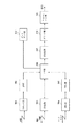
次に、MFP104の構成について説明する。図2は、MFP104の構成を示すブロック図である。図示するように、MFP104は、画像の読み取りを行うスキャナ部201と、読み取られた画像データを画像処理するIP部202と、ファクシミリなどに代表される電話回線を利用して画像データの送受信を行うFAX部203と、ネットワークを利用して画像データや装置情報をやりとりするNIC(Network Interface Card)部204と、NIC部204を介してコンピュータから送られてきたページ記述言語(PDL)で記述されたデータをビットマップイメージデータに展開するPDL部205と、MFP104の使い方に応じて画像データを一時保存したり、経路を決定するコア部206と、コア部206から出力された画像データに対してパルス幅変調(PWM)を行うPWM部207と、画像形成を行うプリンタ部208と、用紙の出力仕上げの処理を行うフィニッシャ部209と、画像をプリントせずに済ませるための、或いは、プリント状態の是非を判断するためのプレビュー機能を提供するディスプレイ部210とを有する。
【0048】
<スキャナ部201>
次に、スキャナ部201の構成及び動作について説明する。図3は、スキャナ部201の構成を示す図である。原稿を複写するときには、原稿台ガラス301に読み取られるべき原稿302が置かれる。原稿302は照明303により照射され、ミラー304,305,306を経て光学系307により、CCD308上に像が結ばれる。更に、モータ309により、ミラー304、照明303を含む第1ミラーユニット310が図中の矢印方向に速度vで機械的に駆動され、ミラー305、306を含む第2ミラーユニット311が図中の矢印方向に速度1/2vで駆動され、原稿302の全面が走査される。
【0049】
<画像処理(IP)部202>
次に、画像処理部202について説明する。図4は、画像処理部202の構成を示すブロック図である。入力された光学的信号は、CCDセンサ308により電気信号に変換される。このCCDセンサ308はRGBラインのカラーセンサであり、RGBそれぞれの電気信号がA/D変換部401に入力される。ここで、ゲイン調整、オフセット調整が行われた後、A/Dコンバータで各色信号毎に8bitのデジタル画像信号R0,G0,B0が生成される。その後、シェーディング補正回路402で色毎に基準白色板の読み取り信号を用いた公知のシェーディング補正が施される。更に、CCDセンサ308の各色ラインセンサは、相互に所定の距離を隔てて配置されているため、ラインディレイ調整回路403により副走査方向の空間的ずれが補正される。
【0050】
次に、入力マスキング部404は、CCDセンサ308のR,G,Bフィルタの分光特性で決まる読取色空間をNTSCの標準色空間に変換するものであり、CCDセンサ308の感度特性/照明ランプのスペクトル特性等の諸特性を考慮した装置固有の定数を用いた3×3のマトリックス演算を行い、入力された輝度信号(R0,G0,B0)を標準的な輝度信号(R,G,B)に変換する。
【0051】
更に、輝度/濃度変換部(LOG変換部)405はルック・アップ・テーブル(LUT)により構成され、RGBの輝度信号がC1,M1,Y1の濃度信号になるように変換される。
【0052】
次に、出力マスキング/UCR回路部406は、M1,C1,Y1信号を画像形成装置のトナー色であるY,M,C,K信号にマトリクス演算を用いて変換する部分であり、CCDセンサ308で読み込まれたRGB信号に基づいたC1,M1,Y1,K1信号をトナーの分光分布特性に基づいたC,M,Y,K信号に補正して出力する。そして、ガンマ補正部407にてトナーの色味諸特性を考慮したルック・アップ・テーブル(LUT)を使って画像出力のためのC,M,Y,Kデータに変換され、空間フィルタ408ではシャープネス又はスムージングが施された後、画像信号はコア部206へと送られる。
【0053】
<FAX部203>
次に、FAX部203について説明する。図5は、FAX部203の構成を示すブロック図である。まず、受信時には、電話回線から送られてきたデータをNCU部501で受け取り電圧の変換を行い、モデム部502内の復調部504でA/D変換及び復調操作を行った後、伸張部506でラスタデータに展開する。一般に、FAXでの圧縮伸張にはランレングス法などが用いられるが、公知であるためここではその説明を割愛する。ラスタデータは、メモリ部507に一時保管され、転送エラーがないことが確認された後、コア部206へ送られる。
【0054】
次に、送信時には、コア部206から転送されてきたラスタデータに、圧縮部505でランレングス法などの圧縮を施し、モデム部502内の変調部503にてD/A変換及び変調操作を行った後、NCU部501を介して電話回線へと送られる。
【0055】
<NIC部204>
次に、NIC部204について説明する。図6は、NIC部204及びPDL部205の構成を示すブロック図である。NIC部204は、図1に示すネットワーク101に対するインターフェイス機能を提供するものである。例えば、10Base-Tなどのイーサネット(Ethernet)ケーブルなどを介して、外部装置から情報を入手したり、外部装置へ情報を流す役割を果たす。
【0056】
ネットワークを介して外部装置より情報を入手する場合は、まず、トランス部601で電圧が変換され、LANコントローラ部602へ送られる。LANコントローラ部602は、その内部にバッファメモリ1(不図示)を備えており、その情報が必要な情報か否かを判断した上で、バッファメモリ2(不図示)に送出後、PDL部205へ信号を出力する。
【0057】
次に、外部に情報を提供する場合には、PDL部205より送られてきたデータにLANコントローラ部602で必要な情報が付加され、トランス部601を経由してネットワークに転送される。
【0058】
<PDL部205>
次に、図6を用いてPDL部205について説明する。コンピュータ上で動作するアプリケーションソフトウェアによって作成された画像は、文書、図形、写真などから構成されている。この画像を表すデータは、それぞれ文字コード、図形コード及びラスタ画像データなどによる画像記述の要素の組み合わせから成っている。そして、これらが、いわゆる、PDL(Page Description Language:ページ記述言語)で記述される。PDL部205は、上述のPDLで記述されたデータ(以下、PDLデータという)からビットマップイメージデータへの変換処理を行なう部分である。
【0059】
NIC部204から送られてきたPDLデータは、一旦ハードディスク(HDD)のような大容量メモリ604に格納され、ここでジョブ毎に管理、保存される。次に、必要に応じて、CPU603はRIP(Raster Image Processing)と呼ばれるラスタ化画像処理を実行して、PDLデータをラスタイメージデータに展開する。展開されたラスタイメージデータは、DRAMなどの高速アクセス可能なメモリ605にジョブ毎にページ単位で格納され、プリンタ部208の状況に合わせてコア部206へ送られる。
【0060】
<コア部206>
次に、コア部206について説明する。図7は、コア部206の構成を示すブロック図である。コア部206内のバスセレクタ部701は、MFP104内において、いわば交通整理の役割を担っている。即ち、バスセレクタ部701は、スタンドアローンとしての複写機能、ネットワークスキャン、ネットワークプリント、ファクシミリ送信/受信、ディスプレイ表示など、MFP104の機能に応じてバスの切り替えを行うものである。
【0061】
具体的に詳述するならば、機能に応じて、以下のようにデータが流れる。
【0062】
・スタンドアローン複写:スキャナ201→コア206→プリンタ208
・ネットワークスキャン:スキャナ201→コア206→NIC部204
・ネットワークプリント:NIC部204→コア206→プリンタ208
・ファクシミリ送信機能:スキャナ201→コア206→FAX部203
・ファクシミリ受信機能:FAX部203→コア206→プリンタ208
・ディスプレイ表示機能:スキャナ201→コア206→ディスプレイ210
(但し、ディスプレイ表示機能の入力元はFAX部203やNIC部204でも構わない)
【0063】
バスセレクタ部701を出た画像データは、圧縮部702、ハードディスク(HDD)などの大容量メモリからなるメモリ部703、伸張部704を通って、プリンタ部208又はディスプレイ部210へ送られる。ここで用いられる圧縮方式は、JPEG,JBIG,ZIPなど一般的なものであればよい。
【0064】
圧縮部702で圧縮された画像データは、ジョブ毎に管理され、ファイル名、作成者、作成日時、ファイルサイズなどの付加データと一緒にメモリ部703に格納される。更に、ジョブ番号とパスワードが設けられて、それらも一緒にメモリ部703に格納されれば、パーソナルボックス機能をサポートすることもできる。これは、データが一時的に保存されて、特定の人によりプリントアウト(HDDからのデータの読み出し)が行われる機能である。ユーザが、格納されているそれぞれのジョブのうちのあるジョブを指定して呼び出しを行なった場合には、パスワードの認証が行われ、データがHDDより呼び出されて画像伸張され、ラスターイメージデータに戻されてプリンタ部207に送られる。
【0065】
<PWM部207>
次に、PWM部207について説明する。図8は、PWM部207の構成及びパルス幅変調(PWM)を示す図である。まず、コア部206を出たイエロー(Y)、マゼンタ(M)、シアン(C)、ブラック(K)の4色に色分解された画像データは、それぞれのPWM部207を通ってそれぞれ画像形成される。
【0066】
図8において、801は三角波発生部であり、三角波を発生させる。802はD/A変換部であり、入力されたディジタル画像信号をアナログ信号に変換するものである。803はコンパレータであり、図示するように三角波811と画像信号812とを比較し、PWM信号813を出力する。804はレーザ駆動部であり、コンパレータ803からのPWM信号813に従ってCMYKそれぞれのレーザのON/OFFを制御する。805はCMYKそれぞれの半導体レーザであり、レーザビームを照射する。そして、後述するポリゴンスキャナ913によって、それぞれのレーザビームが走査されて、それぞれの感光ドラム917,921,925,929に照射される。
【0067】
<プリンタ部208>
次に、プリンタ部208について説明する。図9は、プリンタ部208の構造を示す側断面図である。図9において、913はポリンゴンミラーであり、4つの半導体レーザ805より発光された4本のレーザー光(CMYK)を受ける。その内のイエロー(Y)はミラー914,915,916を経て感光ドラム917を走査し、次のマゼンタ(M)はミラー918,919,920を経て感光ドラム921を走査し、次のシアン(C)はミラー922,923,924を経て感光ドラム925を走査し、次のブラック(K)はミラー926,927,928を経て感光ドラム929を走査する。
【0068】
一方、930はイエロー(Y)のトナーを供給する現像器であり、レーザー光に従い、感光ドラム917上にイエローのトナー像を形成し、931はマゼンタ(M)のトナーを供給する現像器であり、レーザー光に従い、感光ドラム921上にマゼンタのトナー像を形成し、932はシアン(C)のトナーを供給する現像器であり、レーザー光に従い、感光ドラム925上にシアンのトナー像を形成し、933はブラック(K)のトナーを供給する現像器であり、レーザー光に従い、感光ドラム929上にブラックのトナー像を形成する。以上、4色(Y,M,C,K)のトナー像が用紙に転写され、フルカラーの出力画像を得ることができる。
【0069】
用紙カセット934,935及び手差しトレイ936の何れかより給紙された用紙は、レジストローラ937を経て転写ベルト938上に吸着され、搬送される。また、給紙のタイミングと同期がとられて、予め感光ドラム917,921,925,929には各色のトナーが現像されており、用紙の搬送と共にトナーが用紙に転写される。
【0070】
各色のトナーが転写された用紙は、分離され、搬送ベルト939により搬送され、定着器940によってトナーが用紙に定着される。
【0071】
尚、4つの感光ドラム917,921,925,929は、距離dをおいて、等間隔に配置されており、また、搬送ベルト939により、用紙は一定速度vで搬送されており、このタイミング同期がなされて、4つの半導体レーザ805は駆動される。
【0072】
<フィニッシャ部209>
次に、フィニッシャ部209について説明する。図10は、フィニッシャ部209の構造を示す側断面図である。プリンタ部208の定着部940を出た用紙は、フィニッシャ部209に入力される。図示するように、フィニッシャ部209には、サンプルトレイ1001及びスタックトレイ1002が設けられており、ジョブの種類や排出される用紙の枚数に応じて切り替えられ、それぞれに用紙が排出される。
【0073】
また、ソート方式には、複数のビンを用いて各ビンに振り分けるビンソート方式と、後述する電子ソート機能を用いて、ビン(又はトレイ)を奥方向と手前方向にシフトさせて各ジョブ毎に出力用紙を振り分けるシフトソート方式とがあり、これらの方式により並べ替え(ソーティング:Sorting)が行われる。
【0074】
ここで、電子ソート機能はコレートと呼ばれ、上述のコア部206で説明した大容量メモリが用いられる。バッファメモリを利用して、バッファリングしたページ順と排出順を変更する。
【0075】
また、上述のソーティングがジョブ毎に振り分けるのに対し、ページ毎に種別するグループ機能も有する。更に、スタックトレイ1002に排出する場合には、用紙が排出される前の用紙をジョブ毎に蓄えておき、排出する直前にステープラ1005にてバインドすることも可能である。
【0076】
その他、上述の2つのトレイに至るまでに、紙をZ字状に折るためのZ折り機1004がある。また、ファイル用の2つ(又は3つ)の穴開けを行うパンチャー1006がある。ジョブの種類に応じてそれぞれの処理が行われる。インサータ1003は、中差し機能を行うために用いられ、ここに中差し用の用紙を入れておくことができる。更に、サドルステッチャ1007は、ブックレット形式に紙を二つ折りにし、その真ん中をバインドするために使用する。この場合、バインドされた紙は、ブックレットトレイ1008に排出される。
【0077】
<ディスプレイ部210>
次に、ディスプレイ部210について説明する。図11は、ディスプレイ部210の構成を示す図である。まず、コア部206より出された画像データは、CMYKデータであるため、逆LOG変換部1101でRGBデータに変換する。次に、出力するCRTなどのディスプレイ装置1104の色の特性に合わせるために、ガンマ変換部1102でルックアップテーブルを使用して出力変換が行われる。変換された画像データは、一旦メモリ部1103に格納され、CRTなどのディスプレイ装置1104によって表示される。
【0078】
尚、ディスプレイ部210は、ユーザが出力画像を予め確認するためのプレビュー機能や、ユーザが出力する画像が意図したものと間違いないかを検証するためのプルーフ機能を提供する。或いは、ユーザがプリントの必要がない画像をディスプレイ部210で前もって確認することにより、プリント用紙の無駄が省かれる。
【0079】
<サーバ及びクライアントの構成>
次に、サーバ102及びクライアント103の制御構成に突いて説明する。図38は、以下に説明するネットワークユーティリティソフトウェアが稼動するホストコンピュータであり、図1のサーバ102及びクライアント103を実現するためのホストコンピュータである。
【0080】
CPU3801は、ROM3802もしくはハードディスク(HD)3811、フロッピーディスク(FD)3812などの記憶媒体に記億された、ユーティリティソフトウェアのプログラムを実行し、システムバス3804に接続される各デバイスを総括的に制御する。
【0081】
3803はRAMで、CPU3801の主メモリ、ワークエリア等として機能する。3805はキーボードコントローラ(KBC)で、キーボード(KB)3809や不図示のポインティングデバイスなどからのユーザによる指示入力を制御する。3806はCRTコントローラ(CRTC)で、CRTディスプレイ(CRT)3810の表示を制御する。3807はディスクコントローラ(DKC)で、ブートプログラム、種々のアプリケーション、編集ファイル、ユーザファイル、ネットワークデバイス管理プログラム等を記憶するハードディスク(HD)3811およびフロッピーディスク(FD)3812へのアクセスを制御する。3808はネットワークインターフェースカード(NIC)で、LAN101を介して、MFP104と双方向にデータのやりとりをする。
【0082】
尚、後述のすべての説明において、特に断りの無い限り、実行のハード上の主体はCPU3801であり、ソフトウェア上の主体はハードディスク(HD)311などに記憶されたネットワークユーティリティソフトウェアとする。
【0083】
<ネットワークユーティリティソフトウェアの説明>
ここで、図1に戻り、クライアント103上にて動作するユーティリティソフトウェアについて説明する。MFP104内のネットワークインターフェース部(NIC部204+PDL部205)には、MIB(Management Information Base)と呼ばれる標準化されたデータベースが構築されている。そして、ネットワークインターフェース部は、SNMP(Simple Network Management Protocol)というネットワーク管理プロトコルを介してネットワーク上のコンピュータと通信する。このSNMPとMIBを用いることにより、MFP104や、その他のネットワーク上に接続されたプリンタやFAXなどの管理が実現される。
【0084】
一方、コンピュータ102(又は103)には、ユーティリティソフトウェアと呼ばれるソフトウェアプログラムが動作している。このユーティリティソフトウェアは、SNMPを用いてネットワークを介してMFP104と通信し、MIBを使って必要な情報交換を行なう。
【0085】
例えば、ユーティリティソフトウェアは、MIBを用いて情報の読み出しを行なうことにより、MFP104の装備情報としてフィニッシャ部209が接続されているか否かを検知したり、ステータス情報として現在プリントができるか否かを検知したり、或いは、MFP104の名前や設置場所を検知したりすることができる。更に、MIBを用いて情報を書き込みすることにより、MFP104の名前や設置場所を変更することができる。さらに、全てのクライアントが情報の書き込みができるようにすると、デバイスの管理(デバイス情報に関するデータベースの管理)が難しくなるため、各ユーザの情報のリードライトを制限したり、或いは、サーバ102とクライアント103を区別してリードライトを制限したりすることも可能である。
【0086】
具体的には、図31に示すネットワークに、サーバ102、クライアント103a、クライアント103b、MFP104a,MFP104b、MFP104cがある。それぞれのIPアドレスは、192.168.1.11、192.168.1.51、192.168.1.52、192.168.1.101、192.168.1.102、192.168.1.103である。サブネットマスクは、すべてのデバイスで255.255.255.0と設定されている。
【0087】
このとき、クライアント103bが、IPアドレスを192.168.1.255と指定して、メッセージ(MIBオブジェクト)を送信する。なお、このメッセージは、デバイスの名称を示す“sysDescr”というMIBオブジェクトの値を問い合わせるメッセージである。そして、このメッセージは、ブロードキャストされ、MFP104a、MFP104b、MFP104cによって受信される。それに対して、MFP104aは、メッセージを返す。このメッセージは、登録されている名称が“Device−A”であること(sysDescrのMIB値が“Device−A”であること)を示すメッセージである。MFP104b及びMFP104cも同様なメッセージを返信する。
【0088】
つまり、ユーティリティソフトウェアは、上述の機能を使うことにより、MFP104の装備情報、装置状態、ネットワークの設定、ジョブの経緯、使用状況などあらゆる情報を入手することが可能である。
【0089】
<GUIの説明>
次に、GUI(Graphic User Interface)と呼ばれるコンピュータ102(又は103)上で動作するユーティリティソフトウェアの画面について説明する。図12は、ユーティリティソフトウェアの画面を示す図である。
【0090】
まず、コンピュータ102(又は103)上でユーティリティソフトウェアが起動されると、図12に示すような画面が表示される。ここで1201はウィンドウ、1208がカーソルである。ユーザがマウスを使って、カーソルをウィンドウの所定の部分を指すように動かしてクリックをすると、別のウィンドウが開いたり、ウィンドウが次の状態に遷移する。
【0091】
1202はタイトルバーと呼ばれ、現在のウィンドウの階層やタイトルを表示するのに用いられる。1203〜1207はそれぞれタブと呼ばれ、それぞれの分類ごとに整理されており、ユーザはタブを選択することにより、必要な情報を見たり、必要な情報を選択したりすることができる。図12の例では、1203がデバイスタブと呼ばれ、デバイスの存在とその概要を知ることができる。1204はステータスタブで、それぞれの装置の状態を知ることができる。1205はキュータブで、それぞれの装置内にキューイングされているジョブの様子や、デバイスの混み具合を伺い知ることができる。1206はコンフィグタブで、装置の装備情報を知ることができる。そして、1207はセットアップタブで、装置のネットワーク設定情報を知ることができる。
【0092】
<デバイスタブの説明>
続いて、上述のユーティリティソフトウェアのデバイスタブについて、同じく図12を参照して説明する。まず、デバイスタブ1203をクリックすると、並び替え機能(ソーティング:Sorting)と条件選択機能(セレクティング:Selecting)の項目が現れる。ここで、並べ替え機能とは、ネットワークに接続された複数のMFP104をリスト表示する際に、以下のパラメータに従ってそれらのMFP104をソーティングする機能である。ソーティングには、1211〜1216のような各種パラメータが用意されている。1211は好きなデバイス順にMFP104を並べる。1212はデバイスの設置場所とクライアントの居場所に応じて近い装置の順にMFP104を並べる。1213はデバイスのプリントスピードが早い順或いは遅い順にMFP104を並べる。1214はデバイスの信頼度(例えば、紙ジャムやエラーの発生頻度の低さ)の順にMFP104を並べる。1215はプリント1枚当たりの価格の安いもの順にMFP104を並べる。1216はデバイスの購入時期の新しいもの順にMFP104を並べる。図12には表示されていないが、そのほかMFP104で使用されている消耗品の摩耗度合い、トナー残量、紙残量などMFP104の装置状況や使用度合いに応じて並べ替えを行うことも可能である。
【0093】
条件選択機能とは、デバイスのリスト表示をする際に、表示されるデバイスを条件で絞り込む機能である。条件には、1217〜1222のような各種パラメータが用意されている。1217はネットワーク上でプリント可能な状態にあるデバイス(電源オフのものやジャム処理中のものは選択されない)のみを表示させる。1218はカラー出力(又は入力)可能なデバイスのみを表示させる。1219はFAX機能搭載のデバイスのみを表示させる。1220はスキャナ機能搭載のデバイスのみを表示させる。1221はフィニッシャ機能搭載のデバイスのみを表示させる。1222は上述のパーソナルボックス搭載のデバイスのみを表示させる。
【0094】
また、ここでは表記していないが、これ以外にプリントスピードが何枚以上のデバイスのみを表示させたり、A3/11×17よりも大きなサイズの用紙を出力可能なデバイスのみを表示させたりなど、MFP104の能力や機能に応じて選択条件に当てはまるデバイスのみを表示させることも可能である。
【0095】
以下、ステータスタブ、キュータブ、コンフィグタブ、セットアップタブでも、同様なソーティング機能、セレクティング機能がある。
【0096】
<デバイスランキングの説明>
実際に、図12において、スピード(Faster)1213という項目がクリックされると、ネットワーク上の複数のMFP104が装置のプリント速度の速い順に並べ替えられ、ウィンドウ画面は図13のような表示に遷移する。
【0097】
図13は、スピードのランキング画面を示す図である。この画面では、ネットワーク上に接続された全て(又は一部)のMFP104が、図12で選択されたパラメータ(ここでは、スピード1213)に応じて降べきの順(又は昇べきの順)に並べ替えられて表示されたものである。具体的には、ランキング表示をするために、ユーティリティソフトウェアは、ネットワーク上の全て(又は一部)のMFP104と必要な情報をSNMP/MIBを用いて交信し、ネットワークユーティリティの中でソーティングして表示している。
【0098】
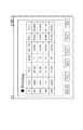
図13において、1301はウィンドウであり、1302はタイトルバーで、このウィンドウの階層を表している。更に、1310はランキングの順位、1311はデバイス名、1312〜1317は図12に表示されたパラメータで、それぞれ好きなデバイス順位、デバイスの場所、デバイスのプリントスピード、デバイスの信頼度、プリント単価、購入時期が併記されてある。
【0099】
また、ウィンドウ下部にある1303〜1309は、別のウィンドウに遷移するためのボタンである。ここで、1306はこのランキング情報に選択条件を与えて絞り込みを行う機能である。1307,1308はランキング表示が複数のページに渡っている場合に、前ページと次ページを表示するボタンである。1309は図12に示す画面に戻るボタンである。
【0100】
次に、1303のグラフボタンがクリックされると、ウィンドウ1301は図14に遷移する。ここでは、図13に示すランキングがグラフ表示され、ユーザがそれぞれのデバイスの能力を判断しやすいように表示される。
【0101】
<デバイスセレクティングの説明>
図17は、図12に示すセレクティングでカラー機(Color Machine)が選択された時に表示されるウィンドウである。このウィンドウでは、ネットワーク全体の中でカラー機が出力(又は入力)可能なデバイスのみが表示されている。更に、各デバイスについて各種パラメータが表示される。
【0102】
絞り込まれたデバイスからその内の1つのデバイスを選んでクリックされると、図16や図21のような詳細情報が現れ、それらのデバイスの仕様や情報の確認が可能となる。
【0103】
<デバイスマップの説明>
更に、図13に示す1304(又は図14に示す1404)がクリックされると、図15に示すようなマップの画面にウィンドウは遷移する。図15は、3階建てのビル内のネットワーク環境を模式的に表した図である。1F,2F,3Fの各階が表示され、A,B,C,1,2,3はそれぞれの階に存在するMFP104の位置を表示している。尚、図13に示す1313は、図15における、階(1F、2F,3F)、縦軸(1、2、3)、横軸(A,B,C)で表記されている。
【0104】
図15において、1501はクライアント103(又はサーバ102)自身の居場所を示している。#01〜#07は図13の順位1310で、それぞれMFP104を示している。それぞれのMFPの所在地が同図より明らかになる。また、この画面を見ることで、クライアント103はどのMFP104に出力すべきかを判断することができる。
【0105】
<各デバイス情報の説明>
図13に示すカーソル1318、図14に示すカーソル1410、図15に示すカーソル1510がそれぞれのウィンドウ内のデバイスを指しているときにクリックされると、それぞれのデバイスの情報が図16に示すように表示される。尚、図16では複数個表示されているが、1つのデバイスを選択した場合は、そのデバイスに関する1つウィンドウが表示される。ここでは、図13に示すパラメータ表示で表示しきれなかった詳細なパラメータや装置の情報をユーザは得ることができる。
【0106】
更に、図13に示す1305、図14に示す1405及び、図15に示す1505をカーソルが指しているときにでクリックされると、図16に示すように全て(又は一部)のデバイスの詳細情報が一度に表示されることが可能である。
【0107】
<ステータスタブの説明>
次に、ステータスタブ1204がクリックされると、図18に示す画面が現れる。ここでは、図13と同様のソーティングとセレクティングの画面が現れ、ここで例えば、ソーティングの好みの順(More Favorite)が選択されると、ウィンドウは図19に遷移する。図19のウィンドウでは、クライアントの好みの順にデバイス名1902が表示され、それぞれのステータス1903が表示される。同時に、ユーザは、各デバイスの状態が紙ジャムやエラーであるないか(1904)、サービスマンコールがされているか否か(1905)、或いは、電源が入っているかいないか(1906)などをチェックすることができる。また、これ以外にエラー内容を詳細に表示したり、ジャムの発生位置を表示するなど詳細情報を表示することもできる。
【0108】
次に、セレクティングのワーキング(Working)が選択されると、ウィンドウは図22に遷移する。図22のウィンドウでは、使用可能なデバイスのみが選択表示される。
【0109】
また、デバイスタブと同様に、マップがクリックされると、図20に示すようにウィンドウが遷移する。このウインドウでは、どのデバイスが使用可能か、また各デバイスの設置場所がどこであるかが表示される。このとき、図19に示すカーソル1907、図20に示すカーソル2009をあるデバイスに合わせてクリックすると、それらの詳細情報を図21に示すように知ることができる。図21に示すウィンドウでは、デバイスが使用可能か否か、使用不可の場合には使用できない理由(どのようなエラが発生したか)が表示される。
【0110】
<キュータブの説明>
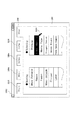
次に、キュータブ1205がクリックされると、図23に示す画面が現れる。ここでは、図13と同様のソーティングとセレクティングの画面が現れる。ここで例えば、ソーティングの近い順(Nearer)が選択されると、ウィンドウは図24に遷移する。そして、このウィンドウでは、クライアント103(又はサーバ102)から位置が近い順に、デバイスがランキング表示される。このとき、2402はデバイス名、2403はデバイスステータスを示す。また、2404は、クライアントのプリント要求後、いまだRIP待ちのキューにあるページ数、2405はRIPは終了したが、いまだプリント待ちのキューにあるページ数を示す。更に、2406は、キューを保持するバッファメモリ(通常はハードディスクに設けられる)のないデバイスで直接プリントする場合のプリント待ちにあるページ数を示す。2407は予想待ち時間を表し、予想待ち時間が“0”(例えば、図24に示すlondon)であるならばすぐ印刷可能である。ユーザは、デバイスの設置位置が多少遠くとも、すぐに出力結果が欲しい場合には、予想待ち時間が0であるデバイスをを選択すればよい。尚、図25に示すマップ画面が表示されることにより、ユーザは、図24の#02:londonがどの位置に存在するのかを確認することができる。
【0111】
また、それぞれのデバイスの具体的な待ち行列の状況も検索が可能である。即ち、図24又は図25の確認したいデバイスがクリックされるか、ウィンドウ下部の情報(Info.)ボタンがクリックされると、ウィンドウは図26に遷移する。このウィンドウでは、それぞれのデバイスに入っているジョブについて、そのジョブを送信したクライアント名、RIPキューのページ数、プリントキューのページ数、ダイレクトキューのページ数、或いは、それぞれのキュー処理にかかる待ち時間などが表示される。各クライアントは、送信したジョブの順番や待ち時間などを予め予想することができる。
【0112】
<コンフィグタブの説明>
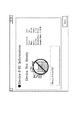
次に、コンフィグタブ1206がクリックされると、図27に示す画面が現れる。この画面は、コンフィグタブを表しており、ユーザは、れぞれのデバイスの装備情報などを知ることができる。例えば、カーソル1208でセレクティングのフィニッシャ(Finisher)を選択すると、ウィンドウが図28のように遷移する。ここでは、2802は、デバイス名、2803〜2810は、各デバイスについてフィニッシャに関する各種機能の可否を示している。例えばサドルステッチ2808の機能を使ってブックレットモードで出力を行ないたい場合には、ユーザは#02:shrimpを選択すればいいことがわかる。
【0113】
<セットアップタブの説明>
次に、セットアップタブ1207がクリックされると、図29に示す画面が現れる。この画面は、セットアップタブを表しており、ユーザはそれぞれのデバイスのネットワークの設定情報などを知ることができる。例えば、カーソル1208でセレクティングのメディアタイプ(Media Type)を選択すると、ウィンドウが図30のように遷移する。ここでは、3002はデバイス名を示し、3003〜3006はメディアタイプに関する各種機能の可否を示している。例えばクライアント103(又はサーバ102)が、100Mbps対応のイーサネット(Ethernet)のネットワークカードを有しており、より早い通信でプリントが行われるためには、ネットワーク上で100Mbps対応のデバイスを探す必要がある。ここで、ユーザは、3004の項目を見て、#01:eagleと#05:swanを選択すればよいことが理解できる。
【0114】
<ネットワークユーティリティの情報取得動作>
図32は、MIB/SNMPを利用して、サーバ102やクライアント103bがそれぞれのMFP104から必要な情報を得るためのフローチャートである。
【0115】
ネットワークユーティリティソフトウェアがサーバ102やクライアント103bで起動されると、まず、必要なMIBオブジェクトの値を取得するためのメッセージをブロードキャストする(ステップS3201)。そして、それぞれのデバイスからMIB値を入手する(ステップS3202)。
【0116】
次に、それぞれのMIB値がある条件を満たすか否かが判定される。なお、この判定は、セレクティング機能が用いられている場合に行なわれる。条件が、たとえば、スピード30PPM(Print Per Minute)以上のデバイスという条件であった場合、ステップS3201でプリントスピードを問い合わせるメッセージが送信され、ステップS3202でデバイスからのそのデバイスのプリントスピードが取得される。そして、ステップS3203で、プリントスピードが30PPM以上のデバイスだけがYesと判定される。条件を満たさなかったデバイスは、ソートされず、このデバイスに関する情報は表示されない。なお、セレクティング機能が用いられていない場合には、全てのデバイスのMIB値が条件を満たすと判定される。
【0117】
次に、ソート順が決められる(ステップS3204)。ユーザの指示により降順の場合には降順でデバイスをソートし(ステップS3205)、昇順の場合には昇順でデバイスをソートする(ステップS3206)。ソートは、ステップS3202で取得されたMIB値に基づいてデバイスがソートされる。
【0118】
全てのMIB値を入手したかをを判定し(ステップS3207)、まだ入手していないデバイスのMIB値がある場合にはステップS3202に戻る。すべてのネットワークデバイスのMIB値が入手されると、今度は表示動作に移行する。ユーティリティソフトウェアであらかじめ決めれた設定に応じて、すべてのデバイスを表示するか否かが判定される(S3209)。全てでない場合には、あらかじめ決められた数のデバイスだけがソートされた順に表示される。全てである場合には、すべてのデバイスがソート順に表示される。
【0119】
<サーバでのデータベース化>
図31ように、クライアントが直接メッセージをブロードキャストする方法では、クライアントが多数ある場合、ネットワークトラフィックが大きくなりすぎてしまう。そこで、図33では、サーバ102だけが各デバイスから情報を取得して、得た情報をデータベース化して管理する。
【0120】
図33を図34を用いて説明する。図33は、サーバ102がMFP104から情報を取得し、クライアント103がサーバ102からMFP104の情報を取得する場合の情報の流れを示す図である。また、図34は、サーバ102とクラインと103の動作を示すフローチャートである。
【0121】
サーバ102はまず、必要なMIBオブジェクトの値を取得するためのメッセージ(C3301)をブロードキャストする(ステップS3401)。そして、各デバイスからMIB値(C3302)を入手し、入手したMIB値をサーバ内のメモリに入れる(ステップS3402)。そして、全てのMIB値を入手したかを判定する(ステップS3403)。
【0122】
全てのデバイスからMIB値を入手した場合には、ステップS3402でメモリに格納されたMIB値をサーバ内のデータベースに格納し、管理する(ステップS3405)。そして、このデータベース化の処理を終了するかどうかを判定し(ステップS3406)、終了しない場合には、一定時間経過するのを待って(ステップS3407)、ステップS3401に戻る。これは、それぞれのデバイスの情報が刻一刻と変化するため、定期的にデータベースの内容を更新するためである。
【0123】
一方、クライアント103は、以下のフローチャートに従って、定期的にサーバ内のデータベースから情報を取得する。まず、サーバのデータベースからデバイスに関する情報を取得する(ステップS3411)。具体的には、デバイスに関する所望の情報をリクエストするメッセージ(C3303)をサーバに送信する。すると、サーバ102は、リクエストされた情報を転送するためのメッセージ(C3304)をクライアント103に送信する。
【0124】
次に、それぞれのデバイス情報の値がある条件を満たすか否かが判定される(ステップS3412)。なお、この判定は、セレクティング機能が用いられている場合に行なわれる。条件を満たさなかったデバイスは、ソートされず、このデバイスに関する情報は表示されない。なお、セレクティング機能が用いられていない場合には、全てのデバイスのMIB値が条件を満たすと判定される。次に、ソート順が決められる(ステップS3413)。ユーザの指示により降順の場合には降順でデバイスをソートし(ステップS3414)、昇順の場合には昇順でデバイスをソートする(ステップS3415)。ソートは、ステップS3411で取得されたデバイス情報の値に基づいてデバイスがソートされる。
【0125】
全てのデバイス情報を入手したかをを判定し(ステップS3416)、まだ入手していないデバイス情報がある場合には、ステップS3411に戻る。すべてのデバイス情報が入手されると、今度は表示処理に移行する(ステップS3416)。ここの表示処理のフローチャートは図35に示す。最後に、デバイス情報の表示が終了されているかを判定し(ステップS3420)、終了されていなければ、一定時間が経過するのを待って(ステップS3421)、ステップS3411に戻る。
【0126】
図35は、表示処理を示すフローチャートである。ユーティリティソフトウェアであらかじめ決めれた設定に応じて、すべてのデバイスを表示するか否かが判定される(S3509)。全てでない場合には、あらかじめ決められた数のデバイスだけがソートされた順に表示される(ステップS3502)。全てである場合には、すべてのデバイスがソート順に表示される(ステップS3503)。
【0127】
<その他の実施の形態>
尚、本発明は複数の機器(例えば、ホストコンピュータ,インタフェイス機器,リーダ,プリンタなど)から構成されるシステムに適用しても、一つの機器からなる装置(例えば、複写機,ファクシミリ装置など)に適用してもよい。
【0128】
また、本発明の目的は前述した実施形態の機能を実現するソフトウェアのプログラムコードを記録した記録媒体を、システム或いは装置に供給し、そのシステム或いは装置のコンピュータ(CPU若しくはMPU)が記録媒体に格納されたプログラムコードを読出し実行することによっても、達成されることは言うまでもない。
【0129】
この場合、記録媒体から読出されたプログラムコード自体が前述した実施形態の機能を実現することになり、そのプログラムコードを記憶した記録媒体は本発明を構成することになる。
【0130】
プログラムコードを供給するための記録媒体としては、例えばフロッピーディスク,ハードディスク,光ディスク,光磁気ディスク,CD−ROM,CD−R,磁気テープ,不揮発性のメモリカード,ROMなどを用いることができる。
【0131】
図39は、CD−ROMなどの記録媒体のメモリマップの一例を示す図である。3901はディレクトリ情報を記憶している領域で、インストールプログラムを記憶している領域3902及びネットワークユーティリティソフトウェアのプログラム3903を記憶している領域の位置を示している。本発明のネットワークユーティリティソフトウェアが図38に示したホストコンピュータにインストールされる際には、まず領域3902に記憶しているインストールプログラムがシステムにロードされ、CPU3801によって実行される。次に、CPU3801によって実行されるインストールプログラムが、ネットワークユーティリティソフトウェアのプログラムを領域3903から読み出して、ハードディスク3811に格納する。
【0132】
本発明を上記記録媒体に適用する場合、その記録媒体には、先に説明したフローチャートに対応するプログラムコードを格納することになる。
【0133】
また、本発明は、前記実施形態の機能を実現するソフトウェアのプログラムコードを記録した記録媒体から、そのプログラムをパソコン通信など通信ラインを介して配信する場合にも適用できることは言うまでもない。本発明の目的は、前述した実施形態における様々な機能を実現するソフトウェアのプログラムコードを、図40に示すように、送出装置4004、例えばHTTPサーバやFTPサーバなどから送出してもらい、それを4005に示されるネットワーク又は公衆回線又は無線などを介して受け取り、そのシステム或は装置のコンピュータ(又はCPU,MPU)がそのプログラムコードを実行することによっても達成されることは言うまでもない。
【0134】
この場合、送出装置から送出されたプログラムコード自体が、前述した実施形態における機能を実現することになり、よって、そのプログラムコードを送出する送出装置は本発明を構成することになる。
【0135】
また、コンピュータが読出したプログラムコードを実行することにより、前述した実施形態の機能が実現されるだけでなく、そのプログラムコードの指示に基づき、コンピュータ上で稼働しているOS(オペレーティングシステム)などが実際の処理の一部又は全部を行い、その処理によって前述した実施形態の機能が実現される場合も含まれることは言うまでもない。
【0136】
更に、記録媒体から読出されたプログラムコードが、コンピュータに挿入された機能拡張ボードやコンピュータに接続された機能拡張ユニットに備わるメモリに書込まれた後、そのプログラムコードの指示に基づき、その機能拡張ボードや機能拡張ユニットに備わるCPUなどが実際の処理の一部又は全部を行い、その処理によって前述した実施形態の機能が実現される場合も含まれることは言うまでもない。
【0137】
【発明の効果】
以上説明した、このような実施形態では、ネットワークに接続された全て(又は一部)のMFPデバイスの情報を入手し、それぞれの装備情報、装置状態、ネットワークの設定、ジョブの経緯、使用状況などあらゆる情報に基づいて、リスト表示されるデバイスを並べ替えたり、絞り込んだりして、ユーザにとって得たい情報をリアルタイムに提供することが可能となる。
【0138】
また、ユーザがこれを利用することで、自分自身の使用目的にマッチしたMFPデバイスを即座に見つけだすことができるため、ユーザにとっても、ネットワーク全体にとっても無駄のない円滑なデバイス管理を可能にする。
【0139】
以上説明したように、本発明によれば、ネットワークに接続された複数の画像形成装置に対して、各ユーザの使用目的に合わせて画像形成装置をリスト表示する際に、所望の順に画像形成装置を並べ替えたり、所望の画像形成装置を即時に検索したりすることができる。さらに、所望の画像形成装置の装備情報、装置状態、ネットワークの設定状況、ジョブの経緯、使用状況をリアルタイムに提供することが可能となる。
【0140】
更に、ランキング、グラフ、マップなど様々な形式のGUIをユーザに提供することにより、ユーザの利便性を向上させることが可能となる。
【図面の簡単な説明】
【図1】実施形態におけるシステムの構成を示す外観図である。
【図2】画像形成装置の構成を示すブロック図である。
【図3】画像形成装置のスキャナ部の構成を示す図である。
【図4】画像形成装置の画像処理部の構成を示すブロック図である。
【図5】画像形成装置のFAX部の構成を示すブロック図である。
【図6】画像形成装置のNIC部及びPDL部の構成を示すブロック図である。
【図7】画像形成装置のコア部の構成を示すブロック図である。
【図8】画像形成装置のPWM部の構成及びパルス幅変調を示す図である。
【図9】画像形成装置のプリンタ部の構造を示す側断面図である。
【図10】画像形成装置のフィニッシャ部の構造を示す側断面図である。
【図11】画像形成装置のディスプレイ部の構成を示す図である。
【図12】ユーティリティソフトのデバイスタブ画面を示す図である。
【図13】ユーティリティソフトのランキング画面1を示す図である。
【図14】ユーティリティソフトのグラフ画面を示す図である。
【図15】ユーティリティソフトのマップ画面1を示す図である。
【図16】ユーティリティソフトのマルチウィンドウ画面1を示す図である。
【図17】ユーティリティソフトのふるい分け画面1を示す図である。
【図18】ユーティリティソフトのステータスタブ画面を示す図である。
【図19】ユーティリティソフトのランキング画面2を示す図である。
【図20】ユーティリティソフトのマップ画面2を示す図である。
【図21】ユーティリティソフトのデバイス情報画面を示す図である。
【図22】ユーティリティソフトのふるい分け画面2を示す図である。
【図23】ユーティリティソフトのキュータブ画面を示す図である。
【図24】ユーティリティソフトのランキング画面3を示す図である。
【図25】ユーティリティソフトのマップ画面3を示す図である。
【図26】ユーティリティソフトのマルチウィンドウ画面2を示す図である。
【図27】ユーティリティソフトのコンフィグタブ画面を示す図である。
【図28】ユーティリティソフトのランキング画面4を示す図である。
【図29】ユーティリティソフトのセットアップタブ画面を示す図である。
【図30】ユーティリティソフトのランキング画面5を示す図である。
【図31】クライアントと画像形成装置間のデータ転送を示す図である。
【図32】ユーティリティソフトの動作を示すフローチャートである。
【図33】サーバ、クライアント、画像形成装置間のデータ転送を示す図である。
【図34】ユーティリティソフトの動作を示すフローチャートである。
【図35】表示処理のフローチャートである。
【図36】ルータが用いられたネットワークの例を示す図である。
【図37】パケットによるデータ転送の様子を示す図である。
【図38】サーバまたはクライアントの制御構成を示すブロック図である。
【図39】メモリマップの一例を示す図である。
【図40】プログラムの供給方法の一例を示す図である。
【符号の説明】
101 LAN
102 サーバ
103a クライアント
103b クライアント
104a MFP
104b MFP
104c MFP[0001]
BACKGROUND OF THE INVENTION
The present invention relates to an information processing apparatus, an information processing method, and a program for displaying information related to a plurality of image processing apparatuses connected to a network.Media containingAbout.
[0002]
[Prior art]
Conventionally, with respect to a plurality of image forming apparatuses connected to a network, all information of the apparatus itself such as equipment information, apparatus state, network setting status, job history, usage status, etc. is acquired and from a computer connected to the same network Network utility software for managing these image forming apparatuses is known.
[0003]
However, this network utility software identifies one image forming apparatus from among a plurality of image forming apparatuses connected on the network, and then installs equipment information, apparatus status, network setting status of the specific image forming apparatus, It was to see the background of the job and the usage status.
[0004]
Further, there has been network utility software that displays only a single parameter simultaneously for a plurality of image forming apparatuses. However, there has been no utility software having a user-friendly GUI (screen) that allows the user to make an immediate determination by displaying part or all of the information.
[0005]
In addition, there is utility software that can rank, rearrange, and search the devices according to parameters that are unique to multiple image forming devices or parameters that represent the capabilities of the image forming devices. I didn't.
[0006]
[Problems to be solved by the invention]
SUMMARY OF THE INVENTION An object of the present invention is to solve the above-described conventional problems, and display a plurality of image forming apparatuses connected to a network by rearranging and displaying the image forming apparatuses in a desired order according to the purpose of use of the user. It is possible to search for an image forming apparatus immediately or to provide the user with equipment information, apparatus status, network setting status, job history, and usage status of a desired image forming apparatus in real time.
[0007]
[Means for Solving the Problems]
To achieve the above object, the present invention is capable of communicating with a plurality of image processing devices connected to a network, and a server device that collects device information from the plurality of image processing devices and manages them in a database, and a display unit An input unit for inputting a display category and display conditions when displaying device information on the plurality of image processing devices on a display unit,The information processing apparatus with respect to the server apparatusThe server deviceofManaged by databaseBe doneRequesting means for requesting device information relating to the plurality of image processing apparatuses, and display conditions input by the input means when displaying device information relating to the plurality of image processing apparatuses acquired as a response to the request by the requesting means Display control means for arranging and displaying device information on the display unit according to the order of the plurality of image processing devices attached based on the display category, and the type of device information to be displayed for each display category is set. The display control means displays the type of device information to be displayed based on the display category input by the input means.
[0008]
Also,An information processing apparatus that can communicate with a plurality of image processing apparatuses connected to a network and includes a display unit, and inputs display categories and display conditions for displaying device information on the plurality of image processing apparatuses on the display unit Input means for requesting, device information relating to the plurality of image processing devices, requesting means for requesting the plurality of image processing devices, and device information relating to the plurality of image processing devices to obtain as response to the request by the requesting means Display means for displaying device information on the display unit in accordance with the display conditions input by the input means, and the type of device information to be displayed is set for each display category. The display control means displays the device information of the type to be displayed based on the display category input by the input means. The features.
[0040]
DETAILED DESCRIPTION OF THE INVENTION
<System overview>
FIG. 1 is an external view showing a configuration of a system in the embodiment. In the figure,
[0041]
Reference numeral 104 denotes a network device connected to the
[0042]
Here, on the computer 102 (or 103), so-called DTP (Desk Top Publishing) application software operates, and various documents and graphics are created or edited. Various documents and graphics created or edited are converted into a PDL language (Page Description Language), sent to the MFP 104 via the
[0043]
On the other hand, the MFP 104 has a communication interface for exchanging information with the computer 102 (or 103) via the
[0044]
The
[0045]
FIG. 33 shows a state of data transfer between devices in such a network. For example, regardless of whether the
[0046]
Device B receives each piece of divided data as described above. Then, the
[0047]
<MFP 104>
Next, the configuration of the MFP 104 will be described. FIG. 2 is a block diagram showing the configuration of the MFP 104. As illustrated, the MFP 104 transmits and receives image data using a
[0048]
<
Next, the configuration and operation of the
[0049]
<Image Processing (IP)
Next, the
[0050]
Next, the
[0051]
Further, a luminance / density conversion unit (LOG conversion unit) 405 is configured by a look-up table (LUT), and converts RGB luminance signals into C1, M1, and Y1 density signals.
[0052]
Next, the output masking /
[0053]
<
Next, the
[0054]
Next, at the time of transmission, the raster data transferred from the
[0055]
<
Next, the
[0056]
When obtaining information from an external device via a network, first, the voltage is converted by the
[0057]
Next, when providing information to the outside, necessary information is added by the
[0058]
<
Next, the
[0059]
The PDL data sent from the
[0060]
<
Next, the
[0061]
More specifically, data flows as follows according to the function.
[0062]
・ Stand-alone copying:
・ Network scan:
-Network printing: NIC unit 204-> core 206->
・ Facsimile transmission function:
-Facsimile reception function: FAX section 203-> core 206->
・ Display function:
(However, the display display function may be input from the
[0063]
The image data output from the
[0064]
The image data compressed by the
[0065]
<
Next, the
[0066]
In FIG. 8,
[0067]
<
Next, the
[0068]
On the other hand, 930 is a developing device that supplies yellow (Y) toner, forms a yellow toner image on the
[0069]
The paper fed from any of the
[0070]
The sheet on which the toner of each color is transferred is separated and conveyed by the
[0071]
The four
[0072]
<
Next, the
[0073]
In addition, the sorting method uses a bin sorting method in which a plurality of bins are allocated to each bin, and an electronic sorting function described later, and bins (or trays) are shifted in the back and front directions and output for each job. There are shift sort methods for sorting the sheets, and sorting (sorting) is performed by these methods.
[0074]
Here, the electronic sort function is called collate, and the large-capacity memory described in the
[0075]
In addition, while the sorting described above is assigned to each job, it also has a group function for classifying each page. Further, when discharging to the
[0076]
In addition, there is a Z-folding
[0077]
<
Next, the
[0078]
The
[0079]
<Configuration of server and client>
Next, the control configuration of the
[0080]
The
[0081]
[0082]
In all the explanations to be described later, the execution hardware main body is the
[0083]
<Description of network utility software>
Returning to FIG. 1, the utility software that runs on the
[0084]
On the other hand, a software program called utility software operates on the computer 102 (or 103). This utility software communicates with the MFP 104 via the network using SNMP, and performs necessary information exchange using the MIB.
[0085]
For example, the utility software reads the information using the MIB, thereby detecting whether the
[0086]
Specifically, the network shown in FIG. 31 includes a
[0087]
At this time, the
[0088]
In other words, the utility software can obtain all kinds of information such as equipment information of the MFP 104, apparatus status, network settings, job history, and usage status by using the above-described functions.
[0089]
<Description of GUI>
Next, a screen of utility software that runs on the computer 102 (or 103) called GUI (Graphic User Interface) will be described. FIG. 12 is a diagram showing a screen of utility software.
[0090]
First, when utility software is started on the computer 102 (or 103), a screen as shown in FIG. 12 is displayed. Here, 1201 is a window and 1208 is a cursor. When the user uses the mouse to move the cursor to a predetermined part of the window and clicks, another window opens or the window changes to the next state.
[0091]
1202 is called a title bar, and is used to display the hierarchy and title of the current window. Each of 1203 to 1207 is called a tab and is arranged for each classification, and the user can view necessary information or select necessary information by selecting the tab. In the example of FIG. 12, 1203 is called a device tab, and the existence of the device and its outline can be known.
[0092]
<Description of device tab>
Next, a device tab of the above-described utility software will be described with reference to FIG. First, when a
[0093]
The condition selection function is a function for narrowing down the devices to be displayed by a condition when displaying a list of devices. Various parameters such as 1217 to 1222 are prepared as conditions.
[0094]
In addition, although not shown here, only devices with a print speed of more than this, or only devices that can output paper of a size larger than A3 / 11 × 17 are displayed. It is also possible to display only devices that meet the selection conditions according to the capabilities and functions of the MFP 104.
[0095]
There are similar sorting and selecting functions on the status tab, queue tab, configuration tab, and setup tab.
[0096]
<Explanation of device ranking>
Actually, in FIG. 12, when an item “Faster” 1213 is clicked, a plurality of MFPs 104 on the network are rearranged in the descending order of the printing speed of the apparatus, and the window screen transitions to a display as shown in FIG. .
[0097]
FIG. 13 is a diagram showing a speed ranking screen. In this screen, all (or a part) of MFPs 104 connected on the network are arranged in descending order (or ascending order) in accordance with the parameter (in this case, speed 1213) selected in FIG. It has been replaced and displayed. Specifically, in order to display the ranking, the utility software communicates with all (or part of) MFPs 104 on the network using SNMP / MIB and sorts and displays the information in the network utility. is doing.
[0098]
In FIG. 13,
[0099]
[0100]
Next, when the
[0101]
<Description of device selecting>
FIG. 17 is a window displayed when a color machine is selected in the selecting shown in FIG. In this window, only devices that can be output (or input) by the color machine in the entire network are displayed. Furthermore, various parameters are displayed for each device.
[0102]
When one of the narrowed-down devices is selected and clicked, detailed information as shown in FIGS. 16 and 21 appears, and the specifications and information of those devices can be confirmed.
[0103]
<Description of device map>
Further, when 1304 shown in FIG. 13 (or 1404 shown in FIG. 14) is clicked, the window changes to a map screen as shown in FIG. FIG. 15 is a diagram schematically showing a network environment in a three-story building. The
[0104]
In FIG. 15,
[0105]
<Description of device information>
When the
[0106]
Further, when the cursor is pointed at 1305 shown in FIG. 13, 1405 shown in FIG. 14, and 1505 shown in FIG. 15, the details of all (or a part of) devices are shown as shown in FIG. 16. Information can be displayed at once.
[0107]
<Description of status tab>
Next, when the
[0108]
Next, when selecting working is selected, the window transitions to FIG. In the window of FIG. 22, only usable devices are selected and displayed.
[0109]
Similarly to the device tab, when the map is clicked, the window changes as shown in FIG. This window displays which devices can be used and where each device is installed. At this time, when the
[0110]
<Description of queue tab>
Next, when the
[0111]
It is also possible to search the specific queue status of each device. That is, when the device to be confirmed shown in FIG. 24 or FIG. 25 is clicked or the information (Info.) Button at the bottom of the window is clicked, the window transitions to FIG. In this window, for each job in each device, the name of the client that sent the job, the number of pages in the RIP queue, the number of pages in the print queue, the number of pages in the direct queue, or the waiting time for each queue processing Etc. are displayed. Each client can predict in advance the order and waiting time of the transmitted jobs.
[0112]
<Description of the configuration tab>
Next, when the
[0113]
<Description of the setup tab>
Next, when the
[0114]
<Network utility information acquisition operation>
FIG. 32 is a flowchart for the
[0115]
When the network utility software is activated on the
[0116]
Next, it is determined whether or not each MIB value satisfies a certain condition. This determination is made when the selecting function is used. If the condition is, for example, a condition of a device having a speed of 30 PPM (Print Per Minute) or more, a message for inquiring about the print speed is transmitted in step S3201, and the print speed of the device from the device is acquired in step S3202. In step S3203, only devices having a print speed of 30 PPM or more are determined to be Yes. Devices that do not meet the conditions are not sorted and information about this device is not displayed. If the selecting function is not used, it is determined that the MIB values of all devices satisfy the condition.
[0117]
Next, the sort order is determined (step S3204). In the descending order according to the user's instruction, the devices are sorted in descending order (step S3205), and in the ascending order, the devices are sorted in ascending order (step S3206). In the sorting, devices are sorted based on the MIB value acquired in step S3202.
[0118]
It is determined whether all MIB values have been obtained (step S3207). If there are MIB values for devices that have not yet been obtained, the process returns to step S3202. When the MIB values of all the network devices are obtained, the display operation is started. It is determined whether or not all devices are to be displayed according to the settings determined in advance by the utility software (S3209). If not all, only a predetermined number of devices are displayed in sorted order. If all, all devices are displayed in sort order.
[0119]
<Create database on server>
As shown in FIG. 31, in the method in which a client broadcasts a message directly, if there are many clients, the network traffic becomes too large. Therefore, in FIG. 33, only the
[0120]
FIG. 33 will be described with reference to FIG. FIG. 33 is a diagram illustrating a flow of information when the
[0121]
First, the
[0122]
When MIB values are obtained from all devices, the MIB values stored in the memory in step S3402 are stored in the database in the server and managed (step S3405). Then, it is determined whether or not to end the database processing (step S3406). If not, the process waits for a fixed time to elapse (step S3407) and returns to step S3401. This is because the information of each device changes every moment, so that the contents of the database are regularly updated.
[0123]
On the other hand, the
[0124]
Next, it is determined whether or not each device information value satisfies a certain condition (step S3412). This determination is made when the selecting function is used. Devices that do not meet the conditions are not sorted and information about this device is not displayed. If the selecting function is not used, it is determined that the MIB values of all devices satisfy the condition. Next, the sort order is determined (step S3413). In the descending order according to the user's instruction, the devices are sorted in descending order (step S3414), and in the ascending order, the devices are sorted in ascending order (step S3415). The sorting is performed based on the device information value acquired in step S3411.
[0125]
It is determined whether all device information has been acquired (step S3416). If there is device information that has not been acquired, the process returns to step S3411. When all device information is obtained, the process proceeds to display processing (step S3416). The flowchart of the display process here is shown in FIG. Finally, it is determined whether the display of device information has been completed (step S3420). If not, the process waits for a certain period of time to elapse (step S3421) and returns to step S3411.
[0126]
FIG. 35 is a flowchart showing the display process. It is determined whether or not all devices are to be displayed according to the settings determined in advance by the utility software (S3509). If not all, only a predetermined number of devices are displayed in the sorted order (step S3502). If it is all, all devices are displayed in the sort order (step S3503).
[0127]
<Other embodiments>
Even if the present invention is applied to a system composed of a plurality of devices (for example, a host computer, interface device, reader, printer, etc.), a device (for example, a copier, a facsimile device, etc.) composed of a single device. You may apply to.
[0128]
Another object of the present invention is to supply a recording medium in which a program code of software realizing the functions of the above-described embodiments is recorded to a system or apparatus, and the computer (CPU or MPU) of the system or apparatus stores the recording medium in the recording medium. Needless to say, this can also be achieved by reading and executing the programmed program code.
[0129]
In this case, the program code itself read from the recording medium realizes the functions of the above-described embodiment, and the recording medium storing the program code constitutes the present invention.
[0130]
As a recording medium for supplying the program code, for example, a floppy disk, a hard disk, an optical disk, a magneto-optical disk, a CD-ROM, a CD-R, a magnetic tape, a nonvolatile memory card, a ROM, or the like can be used.
[0131]
FIG. 39 is a diagram showing an example of a memory map of a recording medium such as a CD-ROM.
[0132]
When the present invention is applied to the recording medium, the recording medium stores program codes corresponding to the flowcharts described above.
[0133]
Further, it goes without saying that the present invention can also be applied to the case where the program is distributed via a communication line such as personal computer communication from a recording medium on which a program code of software that realizes the functions of the above-described embodiments is recorded. The object of the present invention is to have a program code of software that realizes various functions in the above-described embodiment be sent from a sending device 4004, for example, an HTTP server or an FTP server, as shown in FIG. Needless to say, this can also be achieved by the computer (or CPU, MPU) of the system or apparatus executing the program code.
[0134]
In this case, the program code itself sent from the sending device realizes the function in the above-described embodiment, and thus the sending device that sends the program code constitutes the present invention.
[0135]
Further, by executing the program code read by the computer, not only the functions of the above-described embodiments are realized, but also an OS (operating system) operating on the computer based on the instruction of the program code. It goes without saying that a case where the function of the above-described embodiment is realized by performing part or all of the actual processing and the processing is included.
[0136]
Further, after the program code read from the recording medium is written in a memory provided in a function expansion board inserted into the computer or a function expansion unit connected to the computer, the function expansion is performed based on the instruction of the program code. It goes without saying that the CPU or the like provided in the board or the function expansion unit performs part or all of the actual processing and the functions of the above-described embodiments are realized by the processing.
[0137]
【The invention's effect】
In such an embodiment as described above, information on all (or a part) MFP devices connected to the network is obtained, and the respective equipment information, apparatus status, network settings, job history, usage status, etc. Based on all kinds of information, it is possible to rearrange or narrow down the devices displayed in a list, and to provide information desired for the user in real time.
[0138]
In addition, since the user can immediately find an MFP device that matches his / her purpose of use, the user can smoothly manage the device without waste for the user or the entire network.
[0139]
As described above, according to the present invention, when a plurality of image forming apparatuses connected to the network are displayed in a list in accordance with the purpose of use of each user, the image forming apparatuses are in the desired order. Can be rearranged, or a desired image forming apparatus can be searched immediately. Furthermore, it is possible to provide equipment information, apparatus status, network setting status, job history, and usage status of a desired image forming apparatus in real time.
[0140]
Furthermore, by providing the user with various types of GUIs such as rankings, graphs, and maps, it is possible to improve the convenience for the user.
[Brief description of the drawings]
FIG. 1 is an external view showing a configuration of a system in an embodiment.
FIG. 2 is a block diagram illustrating a configuration of an image forming apparatus.
FIG. 3 is a diagram illustrating a configuration of a scanner unit of the image forming apparatus.
FIG. 4 is a block diagram illustrating a configuration of an image processing unit of the image forming apparatus.
FIG. 5 is a block diagram illustrating a configuration of a FAX unit of the image forming apparatus.
FIG. 6 is a block diagram illustrating configurations of a NIC unit and a PDL unit of the image forming apparatus.
FIG. 7 is a block diagram illustrating a configuration of a core unit of the image forming apparatus.
FIG. 8 is a diagram illustrating a configuration of a PWM unit and pulse width modulation of the image forming apparatus.
FIG. 9 is a side sectional view showing a structure of a printer unit of the image forming apparatus.
FIG. 10 is a side sectional view showing a structure of a finisher unit of the image forming apparatus.
FIG. 11 is a diagram illustrating a configuration of a display unit of the image forming apparatus.
FIG. 12 is a diagram showing a device tab screen of utility software.
FIG. 13 is a diagram showing a
FIG. 14 is a diagram showing a graph screen of utility software.
FIG. 15 is a diagram showing a
FIG. 16 is a diagram showing a
FIG. 17 is a diagram showing a
FIG. 18 is a diagram showing a status tab screen of utility software.
FIG. 19 is a diagram showing a
FIG. 20 is a diagram showing a
FIG. 21 is a diagram showing a device information screen of utility software.
FIG. 22 is a diagram showing a
FIG. 23 is a diagram showing a cue tab screen of utility software.
FIG. 24 is a diagram showing a
FIG. 25 is a diagram showing a
FIG. 26 is a diagram showing a
FIG. 27 is a diagram showing a configuration tab screen of utility software.
FIG. 28 is a diagram showing a
FIG. 29 is a diagram showing a setup tab screen of utility software.
FIG. 30 is a diagram showing a
FIG. 31 is a diagram illustrating data transfer between a client and an image forming apparatus.
FIG. 32 is a flowchart showing the operation of the utility software.
FIG. 33 is a diagram illustrating data transfer between a server, a client, and an image forming apparatus.
FIG. 34 is a flowchart showing the operation of the utility software.
FIG. 35 is a flowchart of a display process.
FIG. 36 is a diagram illustrating an example of a network in which a router is used.
FIG. 37 is a diagram illustrating a state of data transfer by a packet.
FIG. 38 is a block diagram showing a control configuration of a server or a client.
FIG. 39 is a diagram illustrating an example of a memory map.
FIG. 40 is a diagram illustrating an example of a program supply method.
[Explanation of symbols]
101 LAN
102 servers
103a client
103b client
104a MFP
104b MFP
104c MFP
Claims (21)
前記複数の画像処理装置に関するデバイス情報を表示部に表示する際の表示カテゴリと表示条件を入力するための入力手段と、
前記情報処理装置が前記サーバ装置に対して、前記サーバ装置のデータベースで管理される前記複数の画像処理装置に関するデバイス情報を要求する要求手段と、
前記要求手段による要求の応答として取得する前記複数の画像処理装置に関するデバイス情報を表示する際に、前記入力手段で入力された表示条件に基づいてつけられる前記複数の画像処理装置の順位に応じて、デバイス情報を並べて前記表示部に表示させる表示制御手段とを有し、
前記表示カテゴリごとに表示すべきデバイス情報の種類が設定され、
前記表示制御手段は、前記入力手段で入力された表示カテゴリに基づいて、表示すべき種類のデバイス情報を表示させることを特徴とする情報処理装置。A plurality of image processing apparatuses connected to a network, and an information processing apparatus capable of communicating with a server apparatus that collects device information from the plurality of image processing apparatuses and manages them in a database, and includes a display unit,
An input means for inputting a display category and a display condition when displaying device information on the plurality of image processing apparatuses on a display unit;
Requesting means for requesting device information relating to the plurality of image processing devices managed by the database of the server device from the information processing device to the server device ;
When displaying device information related to the plurality of image processing apparatuses acquired as a response to the request by the request unit, according to the order of the plurality of image processing apparatuses attached based on the display condition input by the input unit Display control means for displaying device information side by side on the display unit,
The type of device information to be displayed for each display category is set,
The information processing apparatus, wherein the display control unit displays device information of a type to be displayed based on a display category input by the input unit.
前記複数の画像処理装置に関するデバイス情報を表示部に表示する際の表示カテゴリと表示条件を入力するための入力工程と、
前記情報処理装置が前記サーバ装置に対して、前記サーバ装置のデータベースで管理される前記複数の画像処理装置に関するデバイス情報を要求する要求工程と、
前記要求工程における要求の応答として取得する前記複数の画像処理装置に関するデバイス情報を表示する際に、前記入力工程で入力された表示条件に基づいてつけられる前記複数の画像処理装置の順位に応じて、デバイス情報を並べて前記表示部に表示させる表示制御工程とを有し、
前記表示カテゴリごとに表示すべきデバイス情報の種類が設定され、
前記表示制御工程では、前記入力工程で入力された表示カテゴリに基づいて、表示すべき種類のデバイス情報を表示させることを特徴とする情報処理方法。An information processing method in an information processing apparatus that is communicable with a plurality of image processing apparatuses connected to a network and a server apparatus that collects device information from the plurality of image processing apparatuses and manages the information in a database. ,
An input step for inputting a display category and a display condition when displaying device information on the plurality of image processing apparatuses on a display unit;
To the information processing apparatus and the server apparatus, a request step of requesting the device information on the plurality of image processing devices that are managed in the database of the server apparatus,
When displaying device information related to the plurality of image processing devices acquired as a response to the request in the requesting step, according to the order of the plurality of image processing devices attached based on the display condition input in the input step A display control step for displaying device information side by side on the display unit,
The type of device information to be displayed for each display category is set,
In the display control step, the device information of the type to be displayed is displayed based on the display category input in the input step.
前記複数の画像処理装置に関するデバイス情報を表示部に表示する際の表示カテゴリと表示条件を入力するための入力手段と、
前記複数の画像処理装置に関するデバイス情報を、前記複数の画像処理装置に要求する要求手段と、
前記要求手段による要求の応答として取得する前記複数の画像処理装置に関するデバイス情報を表示する際に、前記入力手段で入力された表示条件に応じてデバイス情報を前記表示部に表示させる表示制御手段とを有し、
前記表示カテゴリごとに表示すべきデバイス情報の種類が設定され、
前記表示制御手段は、前記入力手段で入力された表示カテゴリに基づいて、表示すべき種類のデバイス情報を表示させることを特徴とする情報処理装置。An information processing apparatus capable of communicating with a plurality of image processing apparatuses connected to a network and including a display unit,
An input means for inputting a display category and a display condition when displaying device information on the plurality of image processing apparatuses on a display unit;
Request means for requesting device information relating to the plurality of image processing apparatuses to the plurality of image processing apparatuses;
Display control means for displaying device information on the display unit according to a display condition input by the input means when displaying device information regarding the plurality of image processing apparatuses acquired as a response to the request by the request means; Have
The type of device information to be displayed for each display category is set,
The information processing apparatus, wherein the display control unit displays device information of a type to be displayed based on a display category input by the input unit.
Priority Applications (1)
| Application Number | Priority Date | Filing Date | Title |
|---|---|---|---|
| JP2000030354A JP4508336B2 (en) | 1999-02-09 | 2000-02-08 | Information processing apparatus and information processing method for displaying information on image processing apparatus |
Applications Claiming Priority (3)
| Application Number | Priority Date | Filing Date | Title |
|---|---|---|---|
| JP3176999 | 1999-02-09 | ||
| JP11-31769 | 1999-02-09 | ||
| JP2000030354A JP4508336B2 (en) | 1999-02-09 | 2000-02-08 | Information processing apparatus and information processing method for displaying information on image processing apparatus |
Publications (3)
| Publication Number | Publication Date |
|---|---|
| JP2000298540A JP2000298540A (en) | 2000-10-24 |
| JP2000298540A5 JP2000298540A5 (en) | 2007-03-22 |
| JP4508336B2 true JP4508336B2 (en) | 2010-07-21 |
Family
ID=26370285
Family Applications (1)
| Application Number | Title | Priority Date | Filing Date |
|---|---|---|---|
| JP2000030354A Expired - Lifetime JP4508336B2 (en) | 1999-02-09 | 2000-02-08 | Information processing apparatus and information processing method for displaying information on image processing apparatus |
Country Status (1)
| Country | Link |
|---|---|
| JP (1) | JP4508336B2 (en) |
Families Citing this family (12)
| Publication number | Priority date | Publication date | Assignee | Title |
|---|---|---|---|---|
| JP2005173898A (en) * | 2003-12-10 | 2005-06-30 | Ricoh Co Ltd | Information management device and method for managing printer |
| JP4540377B2 (en) * | 2004-03-25 | 2010-09-08 | パナソニック株式会社 | UI display device and UI display method |
| JP2007287060A (en) * | 2006-04-20 | 2007-11-01 | Chugoku Electric Power Co Inc:The | Trouble map system |
| JP4774078B2 (en) | 2008-05-12 | 2011-09-14 | シャープ株式会社 | Information processing device |
| JP5901464B2 (en) | 2012-04-18 | 2016-04-13 | 株式会社Pfu | Image processing system, information processing apparatus, display method, and computer program |
| US9019533B2 (en) * | 2012-11-30 | 2015-04-28 | Ricoh Company, Ltd. | Printer rankings in cloud printing |
| JP6375712B2 (en) * | 2014-06-16 | 2018-08-22 | 富士ゼロックス株式会社 | Information management control device, information management control program |
| JP6233605B2 (en) | 2015-05-29 | 2017-11-22 | コニカミノルタ株式会社 | Management server, program, terminal device |
| JP6689492B2 (en) * | 2016-03-14 | 2020-04-28 | 富士ゼロックス株式会社 | Terminal device, data processing system and program |
| CN108337546B (en) * | 2017-01-20 | 2020-08-28 | 杭州海康威视数字技术股份有限公司 | Target object display method and device |
| JP7365000B2 (en) * | 2019-09-18 | 2023-10-19 | ブラザー工業株式会社 | Computer program, management device, and management method |
| US20210297541A1 (en) * | 2020-03-19 | 2021-09-23 | Toshiba Tec Kabushiki Kaisha | Information processing terminal, image processing system, and method performed by the information processing terminal |
Family Cites Families (2)
| Publication number | Priority date | Publication date | Assignee | Title |
|---|---|---|---|---|
| JPH10187400A (en) * | 1996-12-20 | 1998-07-14 | Canon Inc | Network system, data processing method for network system and recording medium storing program that can be read by computer |
| JPH10240550A (en) * | 1996-12-26 | 1998-09-11 | Canon Inc | Information processor and its method |
-
2000
- 2000-02-08 JP JP2000030354A patent/JP4508336B2/en not_active Expired - Lifetime
Also Published As
| Publication number | Publication date |
|---|---|
| JP2000298540A (en) | 2000-10-24 |
Similar Documents
| Publication | Publication Date | Title |
|---|---|---|
| US7466437B2 (en) | Information processing apparatus for displaying data related to an image forming apparatus, and information processing method therefor | |
| US7809807B2 (en) | Image forming system, image forming method, and server | |
| US7119920B2 (en) | Image formation system | |
| JP4508336B2 (en) | Information processing apparatus and information processing method for displaying information on image processing apparatus | |
| JP4261870B2 (en) | Image forming apparatus, image forming system, and control method for image forming apparatus | |
| JP4789373B2 (en) | Network device management server, control method therefor, and computer program | |
| JP4677148B2 (en) | Information processing apparatus, control method therefor, and computer program | |
| JP3483511B2 (en) | Image forming system, server terminal device, control method in image forming system, storage medium, and management computer | |
| JP2003050689A (en) | Image forming system, image forming method, and server device | |
| JP2003029482A (en) | Image output controller, image forming device, paper delivery processor, image processing system, image processing method, recording medium and program | |
| JP2001296980A (en) | Image forming device system | |
| JP2004255745A (en) | Network device control method | |
| JP2004259058A (en) | Network device control method | |
| JP2005271259A (en) | Printing device and processed data | |
| JP2000112688A (en) | Image formation system | |
| JP4109766B2 (en) | Image forming system | |
| JP3870011B2 (en) | Image forming system, control method, and storage medium | |
| JP2006202022A (en) | Rearrangement device | |
| JP2001216118A (en) | Client terminal equipment, image forming device, server terminal equipment, image forming system, image forming method, and storage medium | |
| JP2003212427A (en) | Image forming system and method | |
| JP2004361706A (en) | Image forming system | |
| JP2006048522A (en) | Image forming processing system, its control method, and program | |
| JP2003162393A (en) | Information processor, job processing method, storage medium, and program | |
| JP2003223293A (en) | Job management apparatus, job management method, storage medium and program | |
| JP4250505B2 (en) | Information processing apparatus, information processing method and information processing program applied to the apparatus |
Legal Events
| Date | Code | Title | Description |
|---|---|---|---|
| A521 | Request for written amendment filed |
Free format text: JAPANESE INTERMEDIATE CODE: A523 Effective date: 20070202 |
|
| A621 | Written request for application examination |
Free format text: JAPANESE INTERMEDIATE CODE: A621 Effective date: 20070202 |
|
| A131 | Notification of reasons for refusal |
Free format text: JAPANESE INTERMEDIATE CODE: A131 Effective date: 20081125 |
|
| A521 | Request for written amendment filed |
Free format text: JAPANESE INTERMEDIATE CODE: A523 Effective date: 20090121 |
|
| A131 | Notification of reasons for refusal |
Free format text: JAPANESE INTERMEDIATE CODE: A131 Effective date: 20091027 |
|
| A521 | Request for written amendment filed |
Free format text: JAPANESE INTERMEDIATE CODE: A523 Effective date: 20091118 |
|
| RD04 | Notification of resignation of power of attorney |
Free format text: JAPANESE INTERMEDIATE CODE: A7424 Effective date: 20100201 |
|
| A131 | Notification of reasons for refusal |
Free format text: JAPANESE INTERMEDIATE CODE: A131 Effective date: 20100323 |
|
| A521 | Request for written amendment filed |
Free format text: JAPANESE INTERMEDIATE CODE: A523 Effective date: 20100325 |
|
| TRDD | Decision of grant or rejection written | ||
| A01 | Written decision to grant a patent or to grant a registration (utility model) |
Free format text: JAPANESE INTERMEDIATE CODE: A01 Effective date: 20100420 |
|
| A01 | Written decision to grant a patent or to grant a registration (utility model) |
Free format text: JAPANESE INTERMEDIATE CODE: A01 |
|
| A61 | First payment of annual fees (during grant procedure) |
Free format text: JAPANESE INTERMEDIATE CODE: A61 Effective date: 20100427 |
|
| FPAY | Renewal fee payment (event date is renewal date of database) |
Free format text: PAYMENT UNTIL: 20130514 Year of fee payment: 3 |
|
| R150 | Certificate of patent or registration of utility model |
Ref document number: 4508336 Country of ref document: JP Free format text: JAPANESE INTERMEDIATE CODE: R150 Free format text: JAPANESE INTERMEDIATE CODE: R150 |
|
| FPAY | Renewal fee payment (event date is renewal date of database) |
Free format text: PAYMENT UNTIL: 20140514 Year of fee payment: 4 |
|
| EXPY | Cancellation because of completion of term |